EP4488021A1 - Fiber preform, fiber preform precursor, and method for manufacturing fiber preform - Google Patents
Fiber preform, fiber preform precursor, and method for manufacturing fiber preform Download PDFInfo
- Publication number
- EP4488021A1 EP4488021A1 EP22929881.5A EP22929881A EP4488021A1 EP 4488021 A1 EP4488021 A1 EP 4488021A1 EP 22929881 A EP22929881 A EP 22929881A EP 4488021 A1 EP4488021 A1 EP 4488021A1
- Authority
- EP
- European Patent Office
- Prior art keywords
- taper portion
- fiber
- fiber preform
- base
- periphery
- Prior art date
- Legal status (The legal status is an assumption and is not a legal conclusion. Google has not performed a legal analysis and makes no representation as to the accuracy of the status listed.)
- Pending
Links
Images









Classifications
-
- B—PERFORMING OPERATIONS; TRANSPORTING
- B29—WORKING OF PLASTICS; WORKING OF SUBSTANCES IN A PLASTIC STATE IN GENERAL
- B29B—PREPARATION OR PRETREATMENT OF THE MATERIAL TO BE SHAPED; MAKING GRANULES OR PREFORMS; RECOVERY OF PLASTICS OR OTHER CONSTITUENTS OF WASTE MATERIAL CONTAINING PLASTICS
- B29B11/00—Making preforms
- B29B11/14—Making preforms characterised by structure or composition
- B29B11/16—Making preforms characterised by structure or composition comprising fillers or reinforcement
-
- B—PERFORMING OPERATIONS; TRANSPORTING
- B29—WORKING OF PLASTICS; WORKING OF SUBSTANCES IN A PLASTIC STATE IN GENERAL
- B29C—SHAPING OR JOINING OF PLASTICS; SHAPING OF MATERIAL IN A PLASTIC STATE, NOT OTHERWISE PROVIDED FOR; AFTER-TREATMENT OF THE SHAPED PRODUCTS, e.g. REPAIRING
- B29C70/00—Shaping composites, i.e. plastics material comprising reinforcements, fillers or preformed parts, e.g. inserts
- B29C70/04—Shaping composites, i.e. plastics material comprising reinforcements, fillers or preformed parts, e.g. inserts comprising reinforcements only, e.g. self-reinforcing plastics
- B29C70/06—Fibrous reinforcements only
- B29C70/08—Fibrous reinforcements only comprising combinations of different forms of fibrous reinforcements incorporated in matrix material, forming one or more layers, and with or without non-reinforced layers
- B29C70/083—Combinations of continuous fibres or fibrous profiled structures oriented in one direction and reinforcements forming a two dimensional structure, e.g. mats
- B29C70/085—Combinations of continuous fibres or fibrous profiled structures oriented in one direction and reinforcements forming a two dimensional structure, e.g. mats the structure being deformed in a three dimensional configuration
-
- B—PERFORMING OPERATIONS; TRANSPORTING
- B29—WORKING OF PLASTICS; WORKING OF SUBSTANCES IN A PLASTIC STATE IN GENERAL
- B29C—SHAPING OR JOINING OF PLASTICS; SHAPING OF MATERIAL IN A PLASTIC STATE, NOT OTHERWISE PROVIDED FOR; AFTER-TREATMENT OF THE SHAPED PRODUCTS, e.g. REPAIRING
- B29C70/00—Shaping composites, i.e. plastics material comprising reinforcements, fillers or preformed parts, e.g. inserts
- B29C70/04—Shaping composites, i.e. plastics material comprising reinforcements, fillers or preformed parts, e.g. inserts comprising reinforcements only, e.g. self-reinforcing plastics
- B29C70/06—Fibrous reinforcements only
- B29C70/10—Fibrous reinforcements only characterised by the structure of fibrous reinforcements, e.g. hollow fibres
- B29C70/16—Fibrous reinforcements only characterised by the structure of fibrous reinforcements, e.g. hollow fibres using fibres of substantial or continuous length
- B29C70/22—Fibrous reinforcements only characterised by the structure of fibrous reinforcements, e.g. hollow fibres using fibres of substantial or continuous length oriented in at least two directions forming a two-dimensional [2D] structure
- B29C70/226—Fibrous reinforcements only characterised by the structure of fibrous reinforcements, e.g. hollow fibres using fibres of substantial or continuous length oriented in at least two directions forming a two-dimensional [2D] structure the structure comprising mainly parallel filaments interconnected by a small number of cross threads
-
- B—PERFORMING OPERATIONS; TRANSPORTING
- B29—WORKING OF PLASTICS; WORKING OF SUBSTANCES IN A PLASTIC STATE IN GENERAL
- B29C—SHAPING OR JOINING OF PLASTICS; SHAPING OF MATERIAL IN A PLASTIC STATE, NOT OTHERWISE PROVIDED FOR; AFTER-TREATMENT OF THE SHAPED PRODUCTS, e.g. REPAIRING
- B29C70/00—Shaping composites, i.e. plastics material comprising reinforcements, fillers or preformed parts, e.g. inserts
- B29C70/04—Shaping composites, i.e. plastics material comprising reinforcements, fillers or preformed parts, e.g. inserts comprising reinforcements only, e.g. self-reinforcing plastics
- B29C70/06—Fibrous reinforcements only
- B29C70/10—Fibrous reinforcements only characterised by the structure of fibrous reinforcements, e.g. hollow fibres
- B29C70/16—Fibrous reinforcements only characterised by the structure of fibrous reinforcements, e.g. hollow fibres using fibres of substantial or continuous length
- B29C70/22—Fibrous reinforcements only characterised by the structure of fibrous reinforcements, e.g. hollow fibres using fibres of substantial or continuous length oriented in at least two directions forming a two-dimensional [2D] structure
- B29C70/228—Fibrous reinforcements only characterised by the structure of fibrous reinforcements, e.g. hollow fibres using fibres of substantial or continuous length oriented in at least two directions forming a two-dimensional [2D] structure the structure being stacked in parallel layers with fibres of adjacent layers crossing at substantial angles
-
- B—PERFORMING OPERATIONS; TRANSPORTING
- B29—WORKING OF PLASTICS; WORKING OF SUBSTANCES IN A PLASTIC STATE IN GENERAL
- B29C—SHAPING OR JOINING OF PLASTICS; SHAPING OF MATERIAL IN A PLASTIC STATE, NOT OTHERWISE PROVIDED FOR; AFTER-TREATMENT OF THE SHAPED PRODUCTS, e.g. REPAIRING
- B29C70/00—Shaping composites, i.e. plastics material comprising reinforcements, fillers or preformed parts, e.g. inserts
- B29C70/04—Shaping composites, i.e. plastics material comprising reinforcements, fillers or preformed parts, e.g. inserts comprising reinforcements only, e.g. self-reinforcing plastics
- B29C70/06—Fibrous reinforcements only
- B29C70/10—Fibrous reinforcements only characterised by the structure of fibrous reinforcements, e.g. hollow fibres
- B29C70/16—Fibrous reinforcements only characterised by the structure of fibrous reinforcements, e.g. hollow fibres using fibres of substantial or continuous length
- B29C70/24—Fibrous reinforcements only characterised by the structure of fibrous reinforcements, e.g. hollow fibres using fibres of substantial or continuous length oriented in at least three directions forming a three-dimensional [3D] structure
-
- B—PERFORMING OPERATIONS; TRANSPORTING
- B29—WORKING OF PLASTICS; WORKING OF SUBSTANCES IN A PLASTIC STATE IN GENERAL
- B29C—SHAPING OR JOINING OF PLASTICS; SHAPING OF MATERIAL IN A PLASTIC STATE, NOT OTHERWISE PROVIDED FOR; AFTER-TREATMENT OF THE SHAPED PRODUCTS, e.g. REPAIRING
- B29C70/00—Shaping composites, i.e. plastics material comprising reinforcements, fillers or preformed parts, e.g. inserts
- B29C70/04—Shaping composites, i.e. plastics material comprising reinforcements, fillers or preformed parts, e.g. inserts comprising reinforcements only, e.g. self-reinforcing plastics
- B29C70/28—Shaping operations therefor
- B29C70/30—Shaping by lay-up, i.e. applying fibres, tape or broadsheet on a mould, former or core; Shaping by spray-up, i.e. spraying of fibres on a mould, former or core
-
- B—PERFORMING OPERATIONS; TRANSPORTING
- B29—WORKING OF PLASTICS; WORKING OF SUBSTANCES IN A PLASTIC STATE IN GENERAL
- B29C—SHAPING OR JOINING OF PLASTICS; SHAPING OF MATERIAL IN A PLASTIC STATE, NOT OTHERWISE PROVIDED FOR; AFTER-TREATMENT OF THE SHAPED PRODUCTS, e.g. REPAIRING
- B29C70/00—Shaping composites, i.e. plastics material comprising reinforcements, fillers or preformed parts, e.g. inserts
- B29C70/04—Shaping composites, i.e. plastics material comprising reinforcements, fillers or preformed parts, e.g. inserts comprising reinforcements only, e.g. self-reinforcing plastics
- B29C70/28—Shaping operations therefor
- B29C70/40—Shaping or impregnating by compression not applied
- B29C70/42—Shaping or impregnating by compression not applied for producing articles of definite length, i.e. discrete articles
- B29C70/44—Shaping or impregnating by compression not applied for producing articles of definite length, i.e. discrete articles using isostatic pressure, e.g. pressure difference-moulding, vacuum bag-moulding, autoclave-moulding or expanding rubber-moulding
- B29C70/443—Shaping or impregnating by compression not applied for producing articles of definite length, i.e. discrete articles using isostatic pressure, e.g. pressure difference-moulding, vacuum bag-moulding, autoclave-moulding or expanding rubber-moulding and impregnating by vacuum or injection
-
- B—PERFORMING OPERATIONS; TRANSPORTING
- B29—WORKING OF PLASTICS; WORKING OF SUBSTANCES IN A PLASTIC STATE IN GENERAL
- B29C—SHAPING OR JOINING OF PLASTICS; SHAPING OF MATERIAL IN A PLASTIC STATE, NOT OTHERWISE PROVIDED FOR; AFTER-TREATMENT OF THE SHAPED PRODUCTS, e.g. REPAIRING
- B29C70/00—Shaping composites, i.e. plastics material comprising reinforcements, fillers or preformed parts, e.g. inserts
- B29C70/04—Shaping composites, i.e. plastics material comprising reinforcements, fillers or preformed parts, e.g. inserts comprising reinforcements only, e.g. self-reinforcing plastics
- B29C70/28—Shaping operations therefor
- B29C70/54—Component parts, details or accessories; Auxiliary operations, e.g. feeding or storage of prepregs or SMC after impregnation or during ageing
- B29C70/543—Fixing the position or configuration of fibrous reinforcements before or during moulding
-
- B—PERFORMING OPERATIONS; TRANSPORTING
- B29—WORKING OF PLASTICS; WORKING OF SUBSTANCES IN A PLASTIC STATE IN GENERAL
- B29C—SHAPING OR JOINING OF PLASTICS; SHAPING OF MATERIAL IN A PLASTIC STATE, NOT OTHERWISE PROVIDED FOR; AFTER-TREATMENT OF THE SHAPED PRODUCTS, e.g. REPAIRING
- B29C70/00—Shaping composites, i.e. plastics material comprising reinforcements, fillers or preformed parts, e.g. inserts
- B29C70/68—Shaping composites, i.e. plastics material comprising reinforcements, fillers or preformed parts, e.g. inserts by incorporating or moulding on preformed parts, e.g. inserts or layers, e.g. foam blocks
- B29C70/681—Component parts, details or accessories; Auxiliary operations
- B29C70/682—Preformed parts characterised by their structure, e.g. form
-
- B—PERFORMING OPERATIONS; TRANSPORTING
- B29—WORKING OF PLASTICS; WORKING OF SUBSTANCES IN A PLASTIC STATE IN GENERAL
- B29C—SHAPING OR JOINING OF PLASTICS; SHAPING OF MATERIAL IN A PLASTIC STATE, NOT OTHERWISE PROVIDED FOR; AFTER-TREATMENT OF THE SHAPED PRODUCTS, e.g. REPAIRING
- B29C70/00—Shaping composites, i.e. plastics material comprising reinforcements, fillers or preformed parts, e.g. inserts
- B29C70/68—Shaping composites, i.e. plastics material comprising reinforcements, fillers or preformed parts, e.g. inserts by incorporating or moulding on preformed parts, e.g. inserts or layers, e.g. foam blocks
- B29C70/86—Incorporated in coherent impregnated reinforcing layers, e.g. by winding
- B29C70/865—Incorporated in coherent impregnated reinforcing layers, e.g. by winding completely encapsulated
-
- B—PERFORMING OPERATIONS; TRANSPORTING
- B32—LAYERED PRODUCTS
- B32B—LAYERED PRODUCTS, i.e. PRODUCTS BUILT-UP OF STRATA OF FLAT OR NON-FLAT, e.g. CELLULAR OR HONEYCOMB, FORM
- B32B1/00—Layered products having a non-planar shape
-
- B—PERFORMING OPERATIONS; TRANSPORTING
- B32—LAYERED PRODUCTS
- B32B—LAYERED PRODUCTS, i.e. PRODUCTS BUILT-UP OF STRATA OF FLAT OR NON-FLAT, e.g. CELLULAR OR HONEYCOMB, FORM
- B32B3/00—Layered products comprising a layer with external or internal discontinuities or unevennesses, or a layer of non-planar shape; Layered products comprising a layer having particular features of form
- B32B3/26—Layered products comprising a layer with external or internal discontinuities or unevennesses, or a layer of non-planar shape; Layered products comprising a layer having particular features of form characterised by a particular shape of the outline of the cross-section of a continuous layer; characterised by a layer with cavities or internal voids ; characterised by an apertured layer
- B32B3/266—Layered products comprising a layer with external or internal discontinuities or unevennesses, or a layer of non-planar shape; Layered products comprising a layer having particular features of form characterised by a particular shape of the outline of the cross-section of a continuous layer; characterised by a layer with cavities or internal voids ; characterised by an apertured layer characterised by an apertured layer, the apertures going through the whole thickness of the layer, e.g. expanded metal, perforated layer, slit layer regular cells B32B3/12
-
- B—PERFORMING OPERATIONS; TRANSPORTING
- B32—LAYERED PRODUCTS
- B32B—LAYERED PRODUCTS, i.e. PRODUCTS BUILT-UP OF STRATA OF FLAT OR NON-FLAT, e.g. CELLULAR OR HONEYCOMB, FORM
- B32B5/00—Layered products characterised by the non- homogeneity or physical structure, i.e. comprising a fibrous, filamentary, particulate or foam layer; Layered products characterised by having a layer differing constitutionally or physically in different parts
- B32B5/02—Layered products characterised by the non- homogeneity or physical structure, i.e. comprising a fibrous, filamentary, particulate or foam layer; Layered products characterised by having a layer differing constitutionally or physically in different parts characterised by structural features of a fibrous or filamentary layer
-
- B—PERFORMING OPERATIONS; TRANSPORTING
- B32—LAYERED PRODUCTS
- B32B—LAYERED PRODUCTS, i.e. PRODUCTS BUILT-UP OF STRATA OF FLAT OR NON-FLAT, e.g. CELLULAR OR HONEYCOMB, FORM
- B32B5/00—Layered products characterised by the non- homogeneity or physical structure, i.e. comprising a fibrous, filamentary, particulate or foam layer; Layered products characterised by having a layer differing constitutionally or physically in different parts
- B32B5/22—Layered products characterised by the non- homogeneity or physical structure, i.e. comprising a fibrous, filamentary, particulate or foam layer; Layered products characterised by having a layer differing constitutionally or physically in different parts characterised by the presence of two or more layers which are next to each other and are fibrous, filamentary, formed of particles or foamed
- B32B5/24—Layered products characterised by the non- homogeneity or physical structure, i.e. comprising a fibrous, filamentary, particulate or foam layer; Layered products characterised by having a layer differing constitutionally or physically in different parts characterised by the presence of two or more layers which are next to each other and are fibrous, filamentary, formed of particles or foamed one layer being a fibrous or filamentary layer
- B32B5/26—Layered products characterised by the non- homogeneity or physical structure, i.e. comprising a fibrous, filamentary, particulate or foam layer; Layered products characterised by having a layer differing constitutionally or physically in different parts characterised by the presence of two or more layers which are next to each other and are fibrous, filamentary, formed of particles or foamed one layer being a fibrous or filamentary layer another layer next to it also being fibrous or filamentary
-
- B—PERFORMING OPERATIONS; TRANSPORTING
- B32—LAYERED PRODUCTS
- B32B—LAYERED PRODUCTS, i.e. PRODUCTS BUILT-UP OF STRATA OF FLAT OR NON-FLAT, e.g. CELLULAR OR HONEYCOMB, FORM
- B32B7/00—Layered products characterised by the relation between layers; Layered products characterised by the relative orientation of features between layers, or by the relative values of a measurable parameter between layers, i.e. products comprising layers having different physical, chemical or physicochemical properties; Layered products characterised by the interconnection of layers
- B32B7/04—Interconnection of layers
- B32B7/08—Interconnection of layers by mechanical means
- B32B7/09—Interconnection of layers by mechanical means by stitching, needling or sewing
-
- B—PERFORMING OPERATIONS; TRANSPORTING
- B32—LAYERED PRODUCTS
- B32B—LAYERED PRODUCTS, i.e. PRODUCTS BUILT-UP OF STRATA OF FLAT OR NON-FLAT, e.g. CELLULAR OR HONEYCOMB, FORM
- B32B7/00—Layered products characterised by the relation between layers; Layered products characterised by the relative orientation of features between layers, or by the relative values of a measurable parameter between layers, i.e. products comprising layers having different physical, chemical or physicochemical properties; Layered products characterised by the interconnection of layers
- B32B7/04—Interconnection of layers
- B32B7/12—Interconnection of layers using interposed adhesives or interposed materials with bonding properties
-
- B—PERFORMING OPERATIONS; TRANSPORTING
- B32—LAYERED PRODUCTS
- B32B—LAYERED PRODUCTS, i.e. PRODUCTS BUILT-UP OF STRATA OF FLAT OR NON-FLAT, e.g. CELLULAR OR HONEYCOMB, FORM
- B32B2250/00—Layers arrangement
- B32B2250/20—All layers being fibrous or filamentary
-
- B—PERFORMING OPERATIONS; TRANSPORTING
- B32—LAYERED PRODUCTS
- B32B—LAYERED PRODUCTS, i.e. PRODUCTS BUILT-UP OF STRATA OF FLAT OR NON-FLAT, e.g. CELLULAR OR HONEYCOMB, FORM
- B32B2307/00—Properties of the layers or laminate
- B32B2307/70—Other properties
- B32B2307/732—Dimensional properties
- B32B2307/737—Dimensions, e.g. volume or area
- B32B2307/7375—Linear, e.g. length, distance or width
Definitions
- the present disclosure relates to a fiber preform for fiber reinforced plastics, a fiber preform precursor for the fiber preform, and a method for manufacturing the fiber preform.
- a sandwich structure including a fiber reinforced plastic layer as an outer layer is used for, for example, an end bell for a power generator.
- An example of a fiber preform as a protruding outer layer may be a fiber fabric or a fiber preform formed by tailored fiber placement (hereafter, TFP).
- TFP a fiber tow is stitched onto a base with fixing threads to be integral with the base for manufacturing a fiber preform, as described in Patent Literature 1.
- Patent Literature 1 Unexamined Japanese Patent Application Publication No. 2014-100911
- the fiber preform with the fiber tow stitched onto the base with fixing threads is formed in a mold.
- the fiber tow may be longer or shorter than the mold. With the fiber tow longer or shorter than the mold, the fiber preform may wrinkle. Known fiber preforms thus have low formability.
- an objective of the present disclosure is to provide a fiber preform with high formability, a fiber preform precursor for the fiber preform, and a method for manufacturing the fiber preform.
- a fiber preform according to an aspect of the present disclosure includes first fiber tows located in a first area on a base, a second fiber tow located in a second area on the base other than the first area and stitched onto the base with a water-insoluble fixing thread, and a fixer located across the first fiber tows to fix parts of the first fiber tows to the base.
- the fixer is a third fiber tow stitched onto the base with a water-insoluble fixing thread, or the fixer is a glue or an elastic adhesive.
- the first fiber tows are displaceable relative to one another.
- the first area is displaceable relative to the second area.
- the parts of the fiber tows in the first area remain unseparated from the base and fixed to allow displacement of the fiber tows relative to one another.
- the first fiber tows are thus displaceable relative to one another, and the first area is displaceable relative to the second area.
- the fiber preform in the above aspect, a fiber preform precursor for the fiber preform, and a method for manufacturing the fiber preform have higher formability.
- a fiber preform, a fiber preform precursor, and a method for manufacturing the fiber preform and the fiber preform precursor according to one or more embodiments of the present disclosure are described in detail below with reference to the drawings. Same reference signs denote same or corresponding components in the drawings.
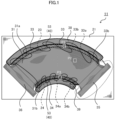
- FIG. 1 is a schematic diagram of a fiber preform precursor 11 according to Embodiment 1.
- FIGS. 2A to 2C are enlarged views of areas P1 to P3 in FIG. 1 .
- the fiber preform precursor 11 is manufactured during manufacture of a fiber preform 12 according to Embodiment 2.
- the fiber preform 12 manufactured using the fiber preform precursor 11 is used as a protruding outer layer of a sandwich panel being a partial disk with a central angle of 90°.
- the fiber preform precursor 11 or the fiber preform 12 is flat and is formed into a protruding shape.
- the partial-disk sandwich panel is used as, for example, an end bell for a power generator.
- the sandwich panel may have a different degree of the central angle or a different shape from the example described in the embodiment.
- the sandwich panel is manufactured, for example, in the manner described below.
- a fiber preform 12 for a protruding outer layer is placed on a female mold 131.
- a foam core 121 and a fiber preform 112 for a smooth outer layer are placed on the fiber preform 12 to hold the foam core 121 between the fiber preforms 12 and 112.
- the foam core 121 between the fiber preforms 12 and 112 and the mold 131 are then covered with a bagging film 132.
- a liquid resin is injected into spaces between the mold 131 and the bagging film 132. The liquid resin cures to complete the sandwich panel.
- the fiber preform precursor 11 includes a base 21 including a fiber fabric, a center portion 31 including fiber tows and water-insoluble fixing threads, an outer taper portion 33 including fiber tows and water-soluble fixing threads, an inner taper portion 34 including fiber tows and water-soluble fixing threads, side portions 35 and 36 each including fiber tows and water-insoluble fixing threads, an outer flange portion 38 including fiber tows and water-insoluble fixing threads, and an inner flange portion 39 including fiber tows and water-insoluble fixing threads.
- the center portion 31, the outer taper portion 33, the inner taper portion 34, the outer flange portion 38, and the inner flange portion 39 each have the shape of a part cut from a ring.
- the outer taper portion 33 extends along an outer periphery 31a of the center portion 31, and the outer flange portion 38 extends along the outer periphery of the outer taper portion 33.
- the inner taper portion 34 extends along an inner periphery 3 1b of the center portion 31, and an inner flange portion 39 extends along the inner periphery of the inner taper portion 34.
- the side portions 35 and 36 are located at both ends of the center portion 31.
- the center portion 31 is located on a protruding flat portion of the foam core
- the outer taper portion 33 is located on an outer slope of the foam core
- the inner taper portion 34 is located on an inner slope of the foam core
- the outer flange portion 38 is located as an outer flange
- the inner flange portion 39 is located as an inner flange.
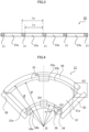
- FIG. 4 illustrates the fiber preform precursor 11 with the dimensions.
- an outer periphery 33a of the outer taper portion 33 is an arc centered on a point O with an outer diameter R o .
- An inner periphery 33b of the outer taper portion 33 is an arc centered on the point O with an inner diameter R i .
- An outer periphery 34a of the inner taper portion 34 is an arc centered on the point O with an outer diameter r o .
- An inner periphery 34b of the inner taper portion 34 is an arc centered on the point O with an inner diameter r i .
- the center portion 31, the outer taper portion 33, and the inner taper portion 34 after the fiber preform 12 is formed are described.
- the height of the outer periphery 31a of the center portion 31 is denoted with H
- the height of the inner periphery 3 1b of the center portion 31 after forming is denoted with h.
- the center portion 31 has a constant height on the inner and outer peripheries. The heights H and h are thus equal to each other.
- the fiber preform 12 according to Embodiment 2 manufactured using the fiber preform precursor 11 in FIG. 1 is formed with a forming mold 60.
- the forming mold 60 has conical surfaces 61 and 62 as illustrated in FIG. 10 .
- the outer taper portion 33 in the fiber preform precursor 11 is formed into a conical surface along the conical surface 61
- the inner taper portion 34 is formed into a conical surface along the conical surface 62.
- the outer taper portion 33 and the inner taper portion 34 are thus tapered after formed into the sandwich panel.
- the outer taper portion 33 and the inner taper portion 34 in the fiber preform precursor 11 illustrated in FIG. 1 are yet to be inclined and are flat.
- a fiber fabric may be used for the base 21.
- the fiber include glass fiber, carbon fiber, and para-aramid fiber, as well as organic fiber such as polyester fiber.
- the fiber tows are stitched onto portions of the base 21 with water-soluble or water-insoluble fixing threads.
- the fixing threads may include upper threads and lower threads.
- the base 21 has multiple dashed outer slits 23 and multiple dashed inner slits 24 in the respective portions to be the outer taper portion 33 or the inner taper portion 34.
- the fiber tows are formed from glass fiber, carbon fiber, or para-aramid fiber.
- the fiber tows may be formed from organic fiber such as polyester fiber.
- the fiber tows fixed to the base 21 with water-soluble fixing threads 56 are herein referred to as first fiber tows 51, and the fiber tows fixed to the base 21 with water-insoluble fixing threads 57 are herein referred to as second fiber tows 52.
- a fixer 40 is also located across the first fiber tows 51 to partially fix the first fiber tows 51.
- the fixer 40 in the present embodiment includes a fiber tow and water-insoluble fixing threads.
- the fiber tow in the fixer 40 is referred to as a third fiber tow 53.
- areas of the base 21 in which the first fiber tows 51 are located are referred to as first areas. Areas of the base 21 other than the first areas in which the second fiber tows 52 are located are referred to as second areas.
- the first fiber tows 51, the second fiber tows 52, and the third fiber tow 53 may all be formed from the same material. Instead, any two of the first fiber tows 51, the second fiber tows 52, and the third fiber tow 53 may be formed from the same material, or the first fiber tows 51, the second fiber tows 52, and the third fiber tow 53 may all be formed from different materials.
- the first fiber tows 51 are fixed to the base 21 with the water-soluble fixing threads 56. More specifically, as illustrated in FIG. 2D , the first fiber tows 51 are stitched with a water-soluble upper thread 56a and a water-soluble lower thread 56b to be fixed to the base 21.
- the water-soluble fixing threads 56 are removable with water, or for example, by immersing the threads in water or spraying the threads with water.
- the water-soluble fixing threads 56 may be formed from a water-soluble material, such as vinylon.
- the second fiber tows 52 are fixed to the base 21 with the water-insoluble fixing threads 57.
- the second fiber tows 52 are also stitched onto the base 21 with a water-insoluble upper thread and a water-insoluble lower thread.
- the material for the water-insoluble fixing threads 57 include glass fiber, carbon fiber, and para-aramid fiber, as well as organic fiber such as polyester fiber or nylon fiber.
- the third fiber tow 53 is located across the first fiber tows 51.
- the third fiber tow 53 is fixed to the base 21 with water-insoluble fixing threads 58.
- the third fiber tow 53 is also stitched onto the base 21 with a water-insoluble upper thread 58a and a water-insoluble lower thread 58b. Parts of the first fiber tows 51 on which the third fiber tow 53 is provided are thus fixed to the base 21.
- the water-insoluble fixing thread 58 may be formed from the same material as or a different material from the water-insoluble fixing threads 57 for fixing the first fiber tows 51.
- the first fiber tows 51 are fixed to the base 21 with the water-soluble fixing threads 56 as illustrated in FIG. 2A in the outer taper portion 33 and the inner taper portion 34, and the third fiber tow 53 fixed with the water-insoluble fixing threads 58 is located across the first fiber tows 51 fixed with the water-soluble fixing threads 56 as illustrated in FIG. 2C .
- areas of the base 21 in which the outer taper portion 33 and the inner taper portion 34 are located correspond to the first areas.
- the second fiber tows 52 are fixed to the base with the water-insoluble fixing threads 57 in portions of the base 21 other than the outer taper 33 and the inner taper 34, or more specifically, in the center portion 31, the outer flange portion 38, the inner flange portion 39, and the side portions 35 and 36.
- the center portion 31, the outer flange 38, the inner flange 39, and the side portions 35 and 36 in the base 21 correspond to the second areas.
- the third fiber tow 53 extends from the outer periphery 33a to the inner periphery 33b of the outer taper portion 33, or from the inner periphery 33b to the outer periphery 33a. The same applies to the inner taper portion 34.
- the third fiber tow 53 extends from the outer periphery 34a to the inner periphery 34b of the inner taper portion 34, or from the inner periphery 34b to the outer periphery 34a.
- the third fiber tow 53 is continuous as a single third fiber tow 53 crossing the outer taper portion 33 and the inner taper portion 34 multiple times. In some embodiments of the present disclosure, however, multiple third fiber tows 53 may be prepared to each extend from the outer periphery 33a to the inner periphery 33b of the outer taper portion 33, or from the inner periphery 33b to the outer periphery 33a. The same applies to the inner taper portion 34.
- the water-soluble fixing threads 56 is removable from the fiber preform precursor 11 through dissolution in water during manufacture of the fiber preform 12.
- parts of the first fiber tows 51 overlapping the third fiber tow 53 in the fiber preform 11 are fixed.
- the first fiber tows 51 are thus displaceable relative to one another, and the first areas in which the first fiber tows 51 are located are displaceable relative to the second areas in which the second fiber tows 52 are located, thus providing higher formability.
- the fiber preform can eliminate creating a cutout or a separate member for reducing wrinkles, and thus can avoid lowering the rigidity of the product.
- being displaceable relative to one another or relative to the second areas refers to being changeable in terms of angles, positions, or both.
- the outer flange portion 38 may be rotated in the circumferential direction of the forming mold 60, or in the direction indicated by the arrows in FIG. 10 , for forming.
- the inner flange portion 39 may be rotated in the circumferential direction of the forming mold 60, or in the direction indicated by the arrows in FIG. 10 , for forming.
- the outer flange portion 38 and the inner flange portion 39 in the fiber preform precursor 11 may be displaced in a direction opposite to the direction of the force applied in forming.
- the outer flange portion 38 is rotated in the circumferential direction of a circle centered on the center O with a radius R o in forming.
- the outer flange portion 38 may thus be rotated, for placement, in the circumferential direction of the circle centered on the point O with the radius R o , or in the direction opposite to the direction of the force applied in forming.
- the outer flange portion 38 may be rotated, for placement, in the circumferential direction of the circle centered on the point O with the radius R o by a height H of the outer periphery 31a of the center portion 31 after forming.
- the length of a rotation by which the outer flange portion 38 is rotated in the circumferential direction may be the same as the height H of the outer periphery 31a of the center portion 31 after forming.
- the amount by which the outer flange portion 38 is rotated may be defined by an angle ⁇ R determined by Formula 1.1.
- R o is the diameter of the outer periphery 33a of the outer taper portion 33
- H is the height of the outer periphery 31a of the center portion 31 after forming.
- BB' indicates the length of the rotation
- AB indicates the width of the outer taper portion.
- the inner flange portion 39 may be rotated, for placement, by a height h of the inner periphery 3 1b of the center portion 31 after forming in the circumferential direction of a circle centered on the point O with a radius r i .
- the length of a rotation by which the inner flange portion 39 is rotated in the circumferential direction may be the same as the height h of the inner periphery 31b of the center portion 31 after forming.
- the amount by which the inner flange portion 39 is rotated may be defined by an angle ⁇ r determined by Formula 1.2 using the diameter r o of the inner periphery 34b of the inner taper portion 34 and the height h of the inner periphery of the center portion 31 after forming.
- ⁇ r tan ⁇ 1 h r i
- the outer flange portion 38 and the inner flange portion 39 are rotated in the direction indicated by the arrows in FIG. 10 , or rightward in FIG. 10 , to be formed.
- the outer flange portion 38 is rotated by ⁇ R
- the inner flange portion 39 is rotated by ⁇ r .
- the outer flange portion 38 and the inner flange portion 39 are placed in the above manner, the outer flange portion 38 is rotated, in forming, by - ⁇ R along the periphery centered on the point O with the radius R o . As illustrated in FIG. 6A , this causes B' to move to a position B on a line extending from the point O through a point A.
- the inner flange portion 39 is rotated by - ⁇ r along the periphery centered on the point O with the radius r;, as illustrated in FIG. 6B , D' moves to a position D on a line extending from the point O through a point C.
- the distance between A and B' in the fiber preform precursor 11 before forming is R o ⁇ R i 2 + H 2
- the distance between C and D' is r o ⁇ r i 2 + h 2 .
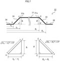
- FIG. 7 schematically illustrates the height of the center portion 31 and the ridgelines of the outer taper portion 33 and the inner taper portion 34 after forming.
- the outer periphery 31a of the center portion 31 after forming has the height H
- the inner periphery 3 1b of the center portion 31 after forming has the height h.
- the distance between E' and F is the difference between the outer diameter R o and the inner diameter R i of the outer taper portion.
- the ridgeline EF of the outer taper portion thus has a length equal to the distance between A and B' in FIG. 6A .
- the distance between J' and K is the difference between the outer diameter r o and the inner diameter r i of the inner taper portion.
- the ridgeline JK thus has a length equal to the distance between C and D' in FIG. 6B .
- the outer slits 23 and the inner slits 24 are located in the first areas on the base 21 in which the first fiber tows 51 are located. As illustrated in FIG. 1 , the outer slits 23 are located in the areas on the base 21 in which the outer taper portion 33 and the inner taper portion 34 are located. The outer slits 23 and the inner slits 24 are in dashed lines.
- the outer slits 23 in the outer taper portion 33 each extend from the outer periphery 33a of the outer taper portion 33 to the inner periphery 33b of the outer taper portion 33.
- the inner slits 24 in the inner taper portion 34 each extend from the outer periphery 34a of the inner taper portion 34 to the inner periphery 34b of the inner taper portion 34.
- the outer slits 23 and inner slits 24 may have no overlap with the fixer 40.
- the outer slits 23 and inner slits 24 may be spaced from the fixer 40.
- each slit when each slit is a single line, or in other words, when each slit has a single opening, the base 21 may be displaced during stitching of the first fiber tows 51, decreasing the formability or workability.
- the outer slits 23 and the inner slits 24 in dashed lines as in the present embodiment can reduce wrinkles on the base 21 or displacement of the base 21 when the first fiber tows 51 are stitched onto the base 21.
- the outer slits 23 each include multiple linear openings 23a each having an opening width Lo and located linearly at a pitch Lp.
- the length Lo of the openings 23a in the dashed outer slits 23 and the pitch Lp between the openings 23a illustrated in FIG.3 may be set as appropriate.
- the length Lo of the openings 23a and the pitch Lp between the openings 23a may be set to values that allow the areas between the openings 23a to be cut off in forming and allow the openings 23a adjacent to one another to be connected to one another.
- the areas between the adjacent slits can undergo shearing deformation in the circumferential direction. This allows the outer taper portion 33 and the inner taper portion 34 to be formed appropriately along the conical surfaces 61 and 62 of the forming mold 60.
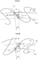
- the outer slits 23 and the inner slits 24 may extend in any direction in the base 21 and may satisfy the relationships described below.
- the outer slits 23 each extend from the outer periphery 33a of the outer taper portion 33 to the inner periphery 33b of the outer taper portion 33.
- an outer slit 23 is located on a line D so .
- the line D so corresponding to the direction in which the outer slit 23 extends may form an angle ⁇ SR defined by Formula 1.3 with a line extending from the point O to an intersection at which the line D so intersects with the inner periphery 33b.
- the outer slits 23 each extend from the outer periphery 33a to the inner periphery 33b.
- the intersection at which the line D so and the inner periphery 33b intersect with each other corresponds to the point A in FIG. 8A .
- ⁇ SR tan ⁇ 1 H R o ⁇ R i
- the inner slits 24 each extend from the outer periphery 34a of the inner taper portion 34 to the inner periphery 34b of the inner taper portion 34.
- an inner slit 24 is located on a line D si .
- the line D si corresponding to the direction in which the inner slit 24 extends may form an angle ⁇ Sr defined by Formula 1.4 with a line extending from the point O to an intersection at which the line D si intersects with the outer periphery 34a.
- the inner slits 24 extend from the inner periphery 34b to the outer periphery 34a.
- the intersection at which the line D si and the outer periphery 34a intersect with each other corresponds to the point C in FIG. 8B .
- ⁇ Sr tan ⁇ 1 h r o ⁇ r i
- the outer slits 23 and the inner slits 24 located at the above angles, as illustrated in FIG. 8A , the outer slits 23 have the same length as the ridgeline EF of the conical surface of the outer taper portion 33 after forming illustrated in FIG. 7 .
- the inner slits 24 have the same length as the ridgeline JK.
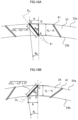
- the fixer 40 may be placed at an angle satisfying the conditions below in the outer taper portion 33. As illustrated in FIG. 9A , the fixer 40 is placed on a line D fo in the outer taper portion 33.
- the line D fo intersects with the inner periphery 33b of the outer taper portion 33 at an intersection.
- a line extending from the point O to the intersection and the line D fo may be in a direction ⁇ SR defined by Formula 1.5.
- ⁇ SR tan ⁇ 1 H R o ⁇ R i
- the fixer 40 may be placed at an angle satisfying the conditions below in the inner taper portion 34.
- the fixer 40 is placed on a line D fi in the inner taper 34.
- the line D fi intersects with the outer periphery 34a of the inner taper 34 at a point.
- a line extending from the point O to the point and the line D fi may be in a direction ⁇ Sr defined by Formula 1.6.
- the point at which the line D fo intersects with the outer periphery 34a of the inner taper portion 34 corresponds to the point C.
- ⁇ Sr tan ⁇ 1 h r o ⁇ r i
- the fixer 40 in the outer taper portion 33 can have the same length as the ridgeline EF of the conical surface of the outer taper portion 33 after forming as illustrated in FIG. 7 .
- the fixer 40 in the inner taper portion 34 can have the same length as the ridgeline JK.
- the fixed first fiber tows 51 are displaceable relative to one another, and parts of the first fiber tows 51 restricted by the fixer 40 can be placed on the same ridgeline of the conical surface of the outer taper portion 33 after forming. This allows the outer taper portion 33 and the inner taper portion 34 to appropriately form into the conical surfaces.
- FIG. 11 illustrates a fiber preform 12 according to Embodiment 2.
- the fiber preform 12 according to the present embodiment is manufactured using the fiber preform precursor 11 according to Embodiment 1.
- FIGS. 12A to 12C are partially enlarged views of areas S1 to S3 in FIG. 11 .
- Like reference signs denote features common with the features in Embodiment 1 and are not described in detail.
- the portion of the base 21 including no fiber tow is cut off, unlike in the fiber preform precursor 11. More specifically, the base 21 remains in areas in which the center portion 31, the outer taper portion 33, the inner taper portion 34, the side portions 35 and 36, the outer flange portion 38, and the inner flange portion 39 are located.
- the water-soluble fixing threads 56 fixing the first fiber tows 51 to the base 21 are removed in the outer taper portion 33 and the inner taper portion 34. Parts of the first fiber tows 51 are fixed to the base 21 with the fixer 40.
- the second fiber tows 52 are fixed to the base 21 with the water-insoluble fixing threads 57 in the center portion 31.
- the second fiber tows 52 are fixed to the base 21 with the water-insoluble fixing threads 57 in the outer taper portion 33, the inner taper portion 34, and the side portions 35 and 36.
- the first fiber tows 51 in the outer taper portion 33 and the inner taper portion 34 are thus displaceable relative to one another. However, with parts of the first fiber tows 51 fixed with the fixer 40, the first fiber tows 51 can remain unseparated from the base 21.
- the fiber preform 12 can thus have higher formability. This structure is particularly effective in forming a fiber preform into a shape with a curved surface.
- the outer flange portion 38, the inner flange portion 39, the outer slits 23, the inner slits 24, and the fixer 40 in the present embodiment may have the features described in Embodiment 1. This allows the outer taper portion 33 and the inner taper portion 34 to appropriately form into conical surfaces.
- a fiber preform precursor 13 according to Embodiment 3 is described with reference to FIG. 13 .
- the fiber preform precursor 13 according to the present embodiment is manufactured during manufacture of a fiber preform 14 according to Embodiment 4 described later.
- the fiber preform precursor 13 according to the present embodiment differs from Embodiments 1 and 2 as shown above in that a glue or an elastic adhesive is used as a fixer 41.
- a glue or an elastic adhesive is used as a fixer 41.
- Like reference signs denote features common with the features in Embodiment 1 and are not described in detail.
- the fiber preform precursor 13 includes the base 21, the center portion 31, the outer taper portion 33, the inner taper portion 34, the side portions 35 and 36, the outer flange portion 38, and the inner flange portion 39.
- the first fiber tows 51 are fixed with the water-soluble fixing threads 56 in the outer taper portion 33 and the inner taper portion 34.
- the second fiber tows 52 are fixed with the water-insoluble fixing threads 57 in the center portion 31, the side portions 35 and 36, the outer flange portion 38, and the inner flange portion 39.
- the fiber preform precursor 13 also has the outer slits 23 and the inner slits 24 as in Embodiment 1.
- the first fiber tows 51 are fixed to the base 21 with the water-soluble fixing threads 56.
- the second fiber tows 52 are fixed to the base 21 with the water-insoluble fixing threads 57.
- the fixer 41 extends from the outer periphery 33a to the inner periphery 33b of the outer taper portion 33, or from the inner periphery 33b to the outer periphery 33a. The same applies to the inner taper portion 34.
- the fixer 41 extends from the outer periphery 34a to the inner periphery 34b of the inner taper portion 34, or from the inner periphery 34b to the outer periphery 34a.
- the fixer 41 is located across the first fiber tows 51. Parts of the first fiber tows 51 on which the fixer 41 is provided on are fixed to the base 21.
- the fixer 41 in the present embodiment is, for example, a glue or an elastic adhesive having flexibility, such as a silicone resin.
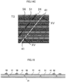
- FIG. 15 is a cross-sectional view taken along line XV-XV in FIG. 14C . As illustrated in FIG. 15 , the fixer 41 is also located between adjacent first fiber tows 51 to fix the first fiber tows 51 to the base 21.
- the fixer 41 restricts the first fiber tows 51 in the outer taper portion 33 and the inner taper portion 34, allowing the first fiber tows 51 to remain unseparated from the base 21.
- the fixer 41 in the present embodiment may be placed as appropriate in the outer taper portion 33 and the inner taper portion 34.
- the fixer 41 may be placed at an angle satisfying the conditions below in the outer taper 33.
- the fixer 41 is placed on the line D fo in the outer taper portion 33.
- the line D fo intersects with the inner periphery 33b of the outer taper portion 33 at an intersection. The intersection corresponds to the point A in FIG. 16A .
- the line extending from the point O to the intersection and the line D fo may be in the direction ⁇ SR defined by Formula 1.5.
- ⁇ SR tan ⁇ 1 H R o ⁇ R i
- the fixer 41 may be placed at an angle satisfying the conditions below in the inner taper portion 34. As illustrated in FIG. 16B , the fixer 41 is placed on the line D fi in the inner taper portion 34.
- the line D fi intersects with the outer periphery 34a of the inner taper portion 34 at an intersection. The intersection corresponds to the point C in FIG. 16B .
- the line extending from the point O to the intersection and the line D fi may be in the direction ⁇ Sr defined by Formula 1.6.
- ⁇ Sr tan ⁇ 1 h r o ⁇ r i
- the fixer 41 placed in the above manner in the outer taper portion 33 can have the same length as the ridgeline EF of the conical surface of the outer taper portion 33 after forming, with the length of the fixer 41 in the outer taper portion 33 illustrated in FIG. 7 .
- outer flange 38 and the inner flange 39 may have the same features as in Embodiment 1.
- the outer slits 23 and the inner slits 24 may also have the same features as in Embodiment 1.
- FIG. 17 illustrates a fiber preform 14 according to Embodiment 4.
- the fiber preform 14 according to the present embodiment is manufactured using the fiber preform precursor 13 according to Embodiment 3.
- FIGS. 18A to 18C are partial enlarged views of areas U1 to U3 in FIG. 17 .
- Like reference signs denote features common with the features in the above embodiments and are not described in detail.
- a portion of the base 21 including no fiber tow is cut off in the present embodiment.
- the second fiber tows 52 in the center portion 31 are fixed with the water-insoluble fixing threads 57.
- the water-soluble fixing threads 56 fixing the first fiber tows 51 to the base 21 are removed in the outer taper portion 33 and the inner taper portion 34.
- the fixer 41 may also be located on the water-soluble fixing threads 56. Although the water-soluble fixing threads 56 are removed with water during manufacture of the fiber preform 14, the water-soluble fixing threads 56 located under the fixer 41 may be left in the fiber preform 14.
- the first fiber tows 51 are displaceable relative to one another in the outer taper portion 33 and the inner taper portion 34.
- the fixer 41 With this structure, the first fiber tows 51 can remain unseparated from the base 21.
- the fiber preform 14 can thus have higher formability.
- This structure is particularly effective in forming a fiber preform into a shape with a curved surface.
- the outer flange portion 38, the inner flange portion 39, the outer slits 23, the inner slits 24, and the fixer 41 in the present embodiment may have the same features as in Embodiments 1 and 3. This allows the outer taper portion 33 and the inner taper portion 34 to form into the conical surfaces more appropriately.
- the dashed outer slits 23 are formed in an area on the base 21 in which the outer taper portion 33 is to be located.
- the inner slits 24 are formed in the base 21 in an area in which the inner taper portion 34 is to be located.
- the first fiber tows 51 are stitched onto the area in which the outer taper portion 33 is to be located with the water-soluble fixing threads 56 using a known automatic sewing machine or a known embroidering machine. Similarly, the first fiber tows 51 are stitched onto the area in which the inner taper portion 34 is to be located with the water-soluble fixing threads 56.
- the second fiber tows 52 are then stitched onto areas of the base 21 without the first fiber tows 51 with the water-insoluble fixing threads 57 using a known automatic sewing machine or a known embroidering machine.
- the second fiber tows 52 are stitched onto the areas in which the center portion 31, the side portions 35 and 36, the outer flange portion 38, and the inner flange portion 39 are to be located.
- the fixer 40 is then placed across the first fiber tows 51 as illustrated in FIG. 22 . More specifically, the third fiber tow 53 is stitched onto the first fiber tows 51 with the water-insoluble fixing thread 58 using a known automatic sewing machine or a known embroidering machine.
- the fiber preform precursor 11 is thus manufactured.
- the outer flange portion 38, the inner flange portion 39, the outer slits 23, the inner slits 24, or the fixer 40 may be formed to satisfy the conditions described in Embodiment 1.
- the water-soluble fixing threads in the fiber preform precursor 11 are then removed with water. More specifically, the fiber preform precursor 11 is immersed in water to dissolve the water-soluble fixing threads. The fiber preform precursor 11 may be sprayed with water to dissolve and remove the water-soluble fixing threads. Unnecessary portions of the base 21 may be cut off and removed.
- the fiber preform 12 can be manufactured.
- the method for manufacturing a fiber preform according to the present disclosure parts of the fiber tows remain unseparated from the base and fixed to allow displacement of the fiber tows relative to one another.
- the fiber preform can thus have higher formability.
- the first fiber tows 51 are fixed with water-soluble fixing threads that are easily removable with water.
- the fiber preform with higher formability can thus be manufactured. Additionally, this method can eliminate creating a cutout in the fiber tows for higher formability and can avoid lowering the rigidity of the formed product.
- the processes of forming the outer slits 23 and the inner slits 24, stitching the first fiber tows 51, and stitching the second fiber tows 52 are performed in the same manner as in Embodiment 5.
- the outer flange portion 38, the inner flange portion 39, the outer slits 23, the inner slits 24, or the fixer 41 may be formed to satisfy the conditions described in Embodiment 1 or 3 in the present embodiment as well.
- the fixer 41 is then placed across the first fiber tows 51. More specifically, the fixer 41 is applied to the first fiber tows 51 fixed with the water-soluble fixing threads 56 using an applicator such as a dispenser to bond the first fiber tows 51 to the base 21.
- an applicator such as a dispenser to bond the first fiber tows 51 to the base 21.
- a material to be cured such as an elastic adhesive, is used for the fixer 41, the process of curing is performed after applying.
- the fiber preform precursor 13 is thus manufactured.
- the water-soluble fixing threads 56 in the fiber preform precursor 13 are then removed with water. More specifically, the fiber preform precursor 13 is immersed in water to dissolve the water-soluble fixing threads 56. The fiber preform precursor 13 may be sprayed with water to dissolve and remove the water-soluble fixing threads 56. The water-soluble fixing threads 56 under the fixer 41 may remain undissolved. Unnecessary portions of the base 21 may be cut off as appropriate.
- the fiber preform 14 can be manufactured.
- the method for manufacturing a fiber preform With the method for manufacturing a fiber preform according to embodiments of the present disclosure, parts of the fiber tows remain unseparated from the base and fixed to allow displacement of the fiber tows relative to one another.
- the fiber preform can thus have higher formability.
- the first fiber tows 51 are fixed with water-soluble fixing threads that are easily removable with water.
- the fiber preform with higher formability can thus be manufactured. Additionally, this method can eliminate creating a cutout in the fiber tows for higher formability and can avoid lowering the rigidity of the formed product.
- the present disclosure is not limited to the above embodiments.
- the outer flange portion 38, the inner flange portion 39, the outer slits 23, the inner slits 24, and the fixers 40 and 41 satisfy the conditions described with the formulas. In some embodiments of the present disclosure, all the conditions may not be satisfied, and any one of the conditions alone may be satisfied.
- the fiber preform precursor and the fiber preform for a partial-disk sandwich panel with a central angle of 90° are illustrated.
- the present disclosure is not limited to the above structure.
- the central angle or the shape may be changed.
- Either the outer taper portion 33 or the inner taper portion 34, rather than both, may be included.
- the fiber preform precursor or the fiber preform to form into a truncated cone may simply include the outer taper portion 33.
Landscapes
- Engineering & Computer Science (AREA)
- Mechanical Engineering (AREA)
- Chemical & Material Sciences (AREA)
- Composite Materials (AREA)
- Textile Engineering (AREA)
- Reinforced Plastic Materials (AREA)
- Moulding By Coating Moulds (AREA)
Abstract
Description
- The present disclosure relates to a fiber preform for fiber reinforced plastics, a fiber preform precursor for the fiber preform, and a method for manufacturing the fiber preform.
- A sandwich structure including a fiber reinforced plastic layer as an outer layer is used for, for example, an end bell for a power generator. An example of a fiber preform as a protruding outer layer may be a fiber fabric or a fiber preform formed by tailored fiber placement (hereafter, TFP).
- With TFP, a fiber tow is stitched onto a base with fixing threads to be integral with the base for manufacturing a fiber preform, as described in
Patent Literature 1. - Patent Literature 1: Unexamined
Japanese Patent Application Publication No. 2014-100911 - The fiber preform with the fiber tow stitched onto the base with fixing threads is formed in a mold. When the fiber preform to be formed in the mold has a curved profile, the fiber tow may be longer or shorter than the mold. With the fiber tow longer or shorter than the mold, the fiber preform may wrinkle. Known fiber preforms thus have low formability.
- Under such circumstances, an objective of the present disclosure is to provide a fiber preform with high formability, a fiber preform precursor for the fiber preform, and a method for manufacturing the fiber preform.
- A fiber preform according to an aspect of the present disclosure includes first fiber tows located in a first area on a base, a second fiber tow located in a second area on the base other than the first area and stitched onto the base with a water-insoluble fixing thread, and a fixer located across the first fiber tows to fix parts of the first fiber tows to the base. The fixer is a third fiber tow stitched onto the base with a water-insoluble fixing thread, or the fixer is a glue or an elastic adhesive. The first fiber tows are displaceable relative to one another. The first area is displaceable relative to the second area.
- In the above aspect of the present disclosure, the parts of the fiber tows in the first area remain unseparated from the base and fixed to allow displacement of the fiber tows relative to one another. The first fiber tows are thus displaceable relative to one another, and the first area is displaceable relative to the second area. The fiber preform in the above aspect, a fiber preform precursor for the fiber preform, and a method for manufacturing the fiber preform have higher formability.
-
-
FIG. 1 is a schematic diagram of a fiber preform precursor according toEmbodiment 1; -
FIG. 2A is an enlarged partial view of area P1 inFIG. 1 ; -
FIG. 2B is an enlarged partial view of area P2 inFIG. 1 ; -
FIG. 2C is an enlarged partial view of area P3 inFIG. 1 ; -
FIG. 2D is a cross-sectional view taken along line IID-IID inFIG. 2C ; -
FIG. 3 is a schematic cross-sectional view of outer slits illustrated inFIG. 1 ; -
FIG. 4 is a diagram of the fiber preform precursor according toEmbodiment 1 with the dimensions; -
FIG. 5A is an enlarged partial view of area Q1 inFIG. 4 ; -
FIG. 5B is an enlarged partial view of area Q2 inFIG. 4 ; -
FIG. 6A is an enlarged partial view of area Q3 inFIG. 4 ; -
FIG. 6B is an enlarged partial view of area Q4 inFIG. 4 ; -
FIG. 7 is a diagram of a fiber preform after forming using the fiber preform precursor according toEmbodiment 1 illustrating the dimensions; -
FIG. 8A is a diagram of the outer slits inEmbodiment 1 illustrating the arrangement; -
FIG. 8B is a diagram of inner slits inEmbodiment 1 illustrating the arrangement; -
FIG. 9A is a diagram of a fixer on an outer taper portion inEmbodiment 1 illustrating the arrangement; -
FIG. 9B is a diagram of the fixer on an inner taper portion inEmbodiment 1 illustrating the arrangement; -
FIG. 10 is a schematic diagram illustrating a method for forming a fiber preform manufactured using the fiber preform precursor according toEmbodiment 1; -
FIG. 11 is a schematic diagram of a fiber preform according to Embodiment 2; -
FIG. 12A is an enlarged partial view of area S1 inFIG. 11 ; -
FIG. 12B is an enlarged partial view of area S2 inFIG. 11 ; -
FIG. 12C is an enlarged partial view of area S3 inFIG. 11 ; -
FIG. 13 is a schematic diagram of a fiber preform precursor according toEmbodiment 3; -
FIG. 14A is an enlarged partial view of area T1 inFIG. 13 ; -
FIG. 14B is an enlarged partial view of area T2 inFIG. 13 ; -
FIG. 14C is an enlarged partial view of area T3 inFIG. 13 ; -
FIG. 15 is a cross-sectional view taken along line XV-XV inFIG. 14C ; -
FIG. 16A is a diagram of a fixer on an outer taper portion inEmbodiment 3 illustrating the arrangement; -
FIG. 16B is a diagram of the fixer on an inner taper portion inEmbodiment 3 illustrating the arrangement; -
FIG. 17 is a schematic diagram of a fiber preform according to Embodiment 4; -
FIG. 18A is an enlarged partial view of area U1 inFIG. 17 ; -
FIG. 18B is an enlarged partial view of area U2 inFIG. 17 ; -
FIG. 18C is an enlarged partial view of area U3 inFIG. 17 ; -
FIG. 19 is a schematic diagram illustrating a method for manufacturing a fiber preform precursor and a fiber preform according to Embodiment 5; -
FIG. 20 is a schematic diagram illustrating the method for manufacturing the fiber preform precursor and the fiber preform according to Embodiment 5; -
FIG. 21 is a schematic diagram illustrating the method for manufacturing the fiber preform precursor and the fiber preform according to Embodiment 5; -
FIG. 22 is a schematic diagram illustrating the method for manufacturing the fiber preform precursor and the fiber preform according to Embodiment 5; -
FIG. 23 is a schematic diagram illustrating the method for manufacturing the fiber preform precursor and the fiber preform according to Embodiment 5; -
FIG. 24 is a schematic diagram illustrating a method for manufacturing a fiber preform precursor and a fiber preform according to Embodiment 6; and -
FIG. 25 is a schematic diagram illustrating a method for manufacturing a sandwich panel in an embodiment of the present disclosure. - A fiber preform, a fiber preform precursor, and a method for manufacturing the fiber preform and the fiber preform precursor according to one or more embodiments of the present disclosure are described in detail below with reference to the drawings. Same reference signs denote same or corresponding components in the drawings.
-
FIG. 1 is a schematic diagram of afiber preform precursor 11 according toEmbodiment 1.FIGS. 2A to 2C are enlarged views of areas P1 to P3 inFIG. 1 . Thefiber preform precursor 11 is manufactured during manufacture of afiber preform 12 according to Embodiment 2. Thefiber preform 12 manufactured using thefiber preform precursor 11 is used as a protruding outer layer of a sandwich panel being a partial disk with a central angle of 90°. Thefiber preform precursor 11 or thefiber preform 12 is flat and is formed into a protruding shape. The partial-disk sandwich panel is used as, for example, an end bell for a power generator. The sandwich panel may have a different degree of the central angle or a different shape from the example described in the embodiment. - The sandwich panel is manufactured, for example, in the manner described below. As illustrated in
FIG. 25 , afiber preform 12 for a protruding outer layer is placed on afemale mold 131. Afoam core 121 and afiber preform 112 for a smooth outer layer are placed on thefiber preform 12 to hold thefoam core 121 between the fiber preforms 12 and 112. Thefoam core 121 between the fiber preforms 12 and 112 and themold 131 are then covered with abagging film 132. A liquid resin is injected into spaces between themold 131 and thebagging film 132. The liquid resin cures to complete the sandwich panel. - As illustrated in
FIG. 1 , thefiber preform precursor 11 includes a base 21 including a fiber fabric, acenter portion 31 including fiber tows and water-insoluble fixing threads, anouter taper portion 33 including fiber tows and water-soluble fixing threads, aninner taper portion 34 including fiber tows and water-soluble fixing threads,side portions outer flange portion 38 including fiber tows and water-insoluble fixing threads, and aninner flange portion 39 including fiber tows and water-insoluble fixing threads. - The
center portion 31, theouter taper portion 33, theinner taper portion 34, theouter flange portion 38, and theinner flange portion 39 each have the shape of a part cut from a ring. Theouter taper portion 33 extends along anouter periphery 31a of thecenter portion 31, and theouter flange portion 38 extends along the outer periphery of theouter taper portion 33. Theinner taper portion 34 extends along aninner periphery 3 1b of thecenter portion 31, and aninner flange portion 39 extends along the inner periphery of theinner taper portion 34. Theside portions center portion 31. When the sandwich panel is completed, as illustrated inFIG. 25 , thecenter portion 31 is located on a protruding flat portion of the foam core, theouter taper portion 33 is located on an outer slope of the foam core, theinner taper portion 34 is located on an inner slope of the foam core, theouter flange portion 38 is located as an outer flange, and theinner flange portion 39 is located as an inner flange. -
FIG. 4 illustrates thefiber preform precursor 11 with the dimensions. As illustrated inFIG. 4 , anouter periphery 33a of theouter taper portion 33 is an arc centered on a point O with an outer diameter Ro. Aninner periphery 33b of theouter taper portion 33 is an arc centered on the point O with an inner diameter Ri. Anouter periphery 34a of theinner taper portion 34 is an arc centered on the point O with an outer diameter ro. Aninner periphery 34b of theinner taper portion 34 is an arc centered on the point O with an inner diameter ri. - The dimensions of the
center portion 31, theouter taper portion 33, and theinner taper portion 34 after thefiber preform 12 is formed are described. As illustrated inFIG. 7 , the height of theouter periphery 31a of thecenter portion 31 is denoted with H, and the height of theinner periphery 3 1b of thecenter portion 31 after forming is denoted with h. In the present embodiment, thecenter portion 31 has a constant height on the inner and outer peripheries. The heights H and h are thus equal to each other. - As illustrated in
FIG. 10 , thefiber preform 12 according to Embodiment 2 manufactured using thefiber preform precursor 11 inFIG. 1 is formed with a formingmold 60. The formingmold 60 hasconical surfaces FIG. 10 . Theouter taper portion 33 in thefiber preform precursor 11 is formed into a conical surface along theconical surface 61, and theinner taper portion 34 is formed into a conical surface along theconical surface 62. Theouter taper portion 33 and theinner taper portion 34 are thus tapered after formed into the sandwich panel. Theouter taper portion 33 and theinner taper portion 34 in thefiber preform precursor 11 illustrated inFIG. 1 are yet to be inclined and are flat. - A fiber fabric may be used for the
base 21. Examples of the fiber include glass fiber, carbon fiber, and para-aramid fiber, as well as organic fiber such as polyester fiber. The fiber tows are stitched onto portions of the base 21 with water-soluble or water-insoluble fixing threads. The fixing threads may include upper threads and lower threads. As indicated by the broken lines inFIG. 1 , thebase 21 has multiple dashedouter slits 23 and multiple dashedinner slits 24 in the respective portions to be theouter taper portion 33 or theinner taper portion 34. - The fiber tows are formed from glass fiber, carbon fiber, or para-aramid fiber. The fiber tows may be formed from organic fiber such as polyester fiber.
- The fiber tows fixed to the base 21 with water-
soluble fixing threads 56 are herein referred to as first fiber tows 51, and the fiber tows fixed to the base 21 with water-insoluble fixing threads 57 are herein referred to as second fiber tows 52. Afixer 40 is also located across the first fiber tows 51 to partially fix the first fiber tows 51. Thefixer 40 in the present embodiment includes a fiber tow and water-insoluble fixing threads. The fiber tow in thefixer 40 is referred to as athird fiber tow 53. In the present embodiment, areas of the base 21 in which the first fiber tows 51 are located are referred to as first areas. Areas of the base 21 other than the first areas in which the second fiber tows 52 are located are referred to as second areas. - The first fiber tows 51, the second fiber tows 52, and the
third fiber tow 53 may all be formed from the same material. Instead, any two of the first fiber tows 51, the second fiber tows 52, and thethird fiber tow 53 may be formed from the same material, or the first fiber tows 51, the second fiber tows 52, and thethird fiber tow 53 may all be formed from different materials. - As illustrated in
FIG. 2A , the first fiber tows 51 are fixed to the base 21 with the water-soluble fixing threads 56. More specifically, as illustrated inFIG. 2D , the first fiber tows 51 are stitched with a water-solubleupper thread 56a and a water-solublelower thread 56b to be fixed to thebase 21. The water-soluble fixing threads 56 are removable with water, or for example, by immersing the threads in water or spraying the threads with water. The water-soluble fixing threads 56 may be formed from a water-soluble material, such as vinylon. - As illustrated in
FIG. 2B , the second fiber tows 52 are fixed to the base 21 with the water-insoluble fixing threads 57. As in the example inFIG. 2D , the second fiber tows 52 are also stitched onto the base 21 with a water-insoluble upper thread and a water-insoluble lower thread. Examples of the material for the water-insoluble fixing threads 57 include glass fiber, carbon fiber, and para-aramid fiber, as well as organic fiber such as polyester fiber or nylon fiber. - As illustrated in
FIG. 2C , thethird fiber tow 53 is located across the first fiber tows 51. Thethird fiber tow 53 is fixed to the base 21 with water-insoluble fixing threads 58. As illustrated inFIG. 2D , thethird fiber tow 53 is also stitched onto the base 21 with a water-insolubleupper thread 58a and a water-insolublelower thread 58b. Parts of the first fiber tows 51 on which thethird fiber tow 53 is provided are thus fixed to thebase 21. The water-insoluble fixing thread 58 may be formed from the same material as or a different material from the water-insoluble fixing threads 57 for fixing the first fiber tows 51. - In the
fiber preform precursor 11 according to the present embodiment, the first fiber tows 51 are fixed to the base 21 with the water-soluble fixing threads 56 as illustrated inFIG. 2A in theouter taper portion 33 and theinner taper portion 34, and thethird fiber tow 53 fixed with the water-insoluble fixing threads 58 is located across the first fiber tows 51 fixed with the water-soluble fixing threads 56 as illustrated inFIG. 2C . Thus, areas of the base 21 in which theouter taper portion 33 and theinner taper portion 34 are located correspond to the first areas. In contrast, the second fiber tows 52 are fixed to the base with the water-insoluble fixing threads 57 in portions of the base 21 other than theouter taper 33 and theinner taper 34, or more specifically, in thecenter portion 31, theouter flange portion 38, theinner flange portion 39, and theside portions center portion 31, theouter flange 38, theinner flange 39, and theside portions - As illustrated in
FIG. 1 , thethird fiber tow 53 extends from theouter periphery 33a to theinner periphery 33b of theouter taper portion 33, or from theinner periphery 33b to theouter periphery 33a. The same applies to theinner taper portion 34. Thethird fiber tow 53 extends from theouter periphery 34a to theinner periphery 34b of theinner taper portion 34, or from theinner periphery 34b to theouter periphery 34a. - In
FIG. 1 , thethird fiber tow 53 is continuous as a singlethird fiber tow 53 crossing theouter taper portion 33 and theinner taper portion 34 multiple times. In some embodiments of the present disclosure, however, multiple third fiber tows 53 may be prepared to each extend from theouter periphery 33a to theinner periphery 33b of theouter taper portion 33, or from theinner periphery 33b to theouter periphery 33a. The same applies to theinner taper portion 34. - The water-
soluble fixing threads 56 is removable from thefiber preform precursor 11 through dissolution in water during manufacture of thefiber preform 12. Thus, parts of the first fiber tows 51 overlapping thethird fiber tow 53 in thefiber preform 11 are fixed. The first fiber tows 51 are thus displaceable relative to one another, and the first areas in which the first fiber tows 51 are located are displaceable relative to the second areas in which the second fiber tows 52 are located, thus providing higher formability. The fiber preform can eliminate creating a cutout or a separate member for reducing wrinkles, and thus can avoid lowering the rigidity of the product. In the embodiments of the present disclosure, being displaceable relative to one another or relative to the second areas refers to being changeable in terms of angles, positions, or both. - For the
outer taper portion 33 to be formed along theconical surface 61 of the formingmold 60 in the above structure, theouter flange portion 38 may be rotated in the circumferential direction of the formingmold 60, or in the direction indicated by the arrows inFIG. 10 , for forming. Similarly, for theinner taper portion 34 to be formed along theconical surface 62 of the formingmold 60, theinner flange portion 39 may be rotated in the circumferential direction of the formingmold 60, or in the direction indicated by the arrows inFIG. 10 , for forming. Thus, theouter flange portion 38 and theinner flange portion 39 in thefiber preform precursor 11 may be displaced in a direction opposite to the direction of the force applied in forming. More specifically, theouter flange portion 38 is rotated in the circumferential direction of a circle centered on the center O with a radius Ro in forming. Theouter flange portion 38 may thus be rotated, for placement, in the circumferential direction of the circle centered on the point O with the radius Ro, or in the direction opposite to the direction of the force applied in forming. - In particular, the
outer flange portion 38 may be rotated, for placement, in the circumferential direction of the circle centered on the point O with the radius Ro by a height H of theouter periphery 31a of thecenter portion 31 after forming. In this case, the length of a rotation by which theouter flange portion 38 is rotated in the circumferential direction may be the same as the height H of theouter periphery 31a of thecenter portion 31 after forming. - As illustrated in
FIG. 5A , the amount by which theouter flange portion 38 is rotated may be defined by an angle θR determined by Formula 1.1. In the formula, Ro is the diameter of theouter periphery 33a of theouter taper portion 33, and H is the height of theouter periphery 31a of thecenter portion 31 after forming. InFIG. 6A , BB' indicates the length of the rotation, and AB indicates the width of the outer taper portion. With Ro greater than H, as illustrated inFIG. 6A , the length of the rotation extends in a tangential direction and is substantially at right angles to a line OA extending from the center O. The angle is thus defined as in Formula 1.1, and ABB' is substantially a right triangle.
- Similarly to the
outer flange portion 38, theinner flange portion 39 may be rotated, for placement, by a height h of theinner periphery 3 1b of thecenter portion 31 after forming in the circumferential direction of a circle centered on the point O with a radius ri. In this case, the length of a rotation by which theinner flange portion 39 is rotated in the circumferential direction may be the same as the height h of theinner periphery 31b of thecenter portion 31 after forming. - Similarly to the outer flange portion, as illustrated in
FIG. 5B , the amount by which theinner flange portion 39 is rotated may be defined by an angle θr determined by Formula 1.2 using the diameter ro of theinner periphery 34b of theinner taper portion 34 and the height h of the inner periphery of thecenter portion 31 after forming. InFIG. 6B , D-D' indicates the rotation periphery, and C-D indicates the width of the inner taper portion. With the diameter ro greater than the height h, as illustrated inFIG. 6B , the rotation periphery extends in a tangential direction and is substantially at right angles to a line extending from the center O. The angle is thus defined as in Formula 1.2, and CDD' is substantially a right triangle.
- In forming, the
outer flange portion 38 and theinner flange portion 39 are rotated in the direction indicated by the arrows inFIG. 10 , or rightward inFIG. 10 , to be formed. Theouter flange portion 38 is rotated by θR, and theinner flange portion 39 is rotated by θr. - In particular, when the
outer flange portion 38 and theinner flange portion 39 are placed in the above manner, theouter flange portion 38 is rotated, in forming, by -θR along the periphery centered on the point O with the radius Ro. As illustrated inFIG. 6A , this causes B' to move to a position B on a line extending from the point O through a point A. When theinner flange portion 39 is rotated by -θr along the periphery centered on the point O with the radius r;, as illustrated inFIG. 6B , D' moves to a position D on a line extending from the point O through a point C. In this case, the distance between A and B' in thefiber preform precursor 11 before forming is

-
FIG. 7 schematically illustrates the height of thecenter portion 31 and the ridgelines of theouter taper portion 33 and theinner taper portion 34 after forming. As illustrated inFIG. 7 , theouter periphery 31a of thecenter portion 31 after forming has the height H, and theinner periphery 3 1b of thecenter portion 31 after forming has the height h. As illustrated inFIG. 7 , the distance between E' and F is the difference between the outer diameter Ro and the inner diameter Ri of the outer taper portion. The ridgeline EF of the outer taper portion thus has a length equal to the distance between A and B' inFIG. 6A . Similarly, the distance between J' and K is the difference between the outer diameter ro and the inner diameter ri of the inner taper portion. The ridgeline JK thus has a length equal to the distance between C and D' inFIG. 6B . With these relationships, theouter taper portion 33 and theinner taper portion 34 in thefiber preform 12 to be manufactured using thefiber preform precursor 11 can be formed appropriately with reduced wrinkles along the outerconical surface 61 and the innerconical surface 62 of the formingmold 60 for a partial-disk sandwich panel illustrated inFIG. 10 . - The
outer slits 23 and theinner slits 24 are located in the first areas on the base 21 in which the first fiber tows 51 are located. As illustrated inFIG. 1 , theouter slits 23 are located in the areas on the base 21 in which theouter taper portion 33 and theinner taper portion 34 are located. Theouter slits 23 and theinner slits 24 are in dashed lines. - As illustrated in
FIG. 1 , theouter slits 23 in theouter taper portion 33 each extend from theouter periphery 33a of theouter taper portion 33 to theinner periphery 33b of theouter taper portion 33. Similarly, theinner slits 24 in theinner taper portion 34 each extend from theouter periphery 34a of theinner taper portion 34 to theinner periphery 34b of theinner taper portion 34. Theouter slits 23 andinner slits 24 may have no overlap with thefixer 40. For example, as illustrated inFIG. 2C , theouter slits 23 andinner slits 24 may be spaced from thefixer 40. - For example, when each slit is a single line, or in other words, when each slit has a single opening, the
base 21 may be displaced during stitching of the first fiber tows 51, decreasing the formability or workability. In contrast, theouter slits 23 and theinner slits 24 in dashed lines as in the present embodiment can reduce wrinkles on the base 21 or displacement of the base 21 when the first fiber tows 51 are stitched onto thebase 21. - As illustrated in
FIG. 3 , theouter slits 23 each include multiplelinear openings 23a each having an opening width Lo and located linearly at a pitch Lp. The same applies to theinner slits 24. The length Lo of theopenings 23a in the dashedouter slits 23 and the pitch Lp between theopenings 23a illustrated inFIG.3 may be set as appropriate. However, the length Lo of theopenings 23a and the pitch Lp between theopenings 23a may be set to values that allow the areas between theopenings 23a to be cut off in forming and allow theopenings 23a adjacent to one another to be connected to one another. The areas between the adjacent slits can undergo shearing deformation in the circumferential direction. This allows theouter taper portion 33 and theinner taper portion 34 to be formed appropriately along theconical surfaces mold 60. - The
outer slits 23 and theinner slits 24 may extend in any direction in thebase 21 and may satisfy the relationships described below. - As illustrated in
FIG. 8A , theouter slits 23 each extend from theouter periphery 33a of theouter taper portion 33 to theinner periphery 33b of theouter taper portion 33. As illustrated inFIG. 8A , anouter slit 23 is located on a line Dso. The line Dso corresponding to the direction in which theouter slit 23 extends may form an angle θSR defined by Formula 1.3 with a line extending from the point O to an intersection at which the line Dso intersects with theinner periphery 33b. InFIG. 8A , theouter slits 23 each extend from theouter periphery 33a to theinner periphery 33b. Thus, the intersection at which the line Dso and theinner periphery 33b intersect with each other corresponds to the point A inFIG. 8A .
- As illustrated in
FIG. 8B , theinner slits 24 each extend from theouter periphery 34a of theinner taper portion 34 to theinner periphery 34b of theinner taper portion 34. As illustrated inFIG. 8B , aninner slit 24 is located on a line Dsi. The line Dsi corresponding to the direction in which theinner slit 24 extends may form an angle θSr defined by Formula 1.4 with a line extending from the point O to an intersection at which the line Dsi intersects with theouter periphery 34a. InFIG. 8B , theinner slits 24 extend from theinner periphery 34b to theouter periphery 34a. Thus, the intersection at which the line Dsi and theouter periphery 34a intersect with each other corresponds to the point C inFIG. 8B .
- With the
outer slits 23 and theinner slits 24 located at the above angles, as illustrated inFIG. 8A , theouter slits 23 have the same length as the ridgeline EF of the conical surface of theouter taper portion 33 after forming illustrated inFIG. 7 . Similarly, theinner slits 24 have the same length as the ridgeline JK. Thus, in forming of thefiber preform 12 to be manufactured using thefiber preform precursor 11, theouter taper portion 33 and theinner taper portion 34 can be formed along the conical surfaces without wrinkles through shear deformation of portions of the base 21 located between adjacent slits. - Additionally, the
fixer 40 may be placed at an angle satisfying the conditions below in theouter taper portion 33. As illustrated inFIG. 9A , thefixer 40 is placed on a line Dfo in theouter taper portion 33. The line Dfo intersects with theinner periphery 33b of theouter taper portion 33 at an intersection. A line extending from the point O to the intersection and the line Dfo may be in a direction θSR defined by Formula 1.5. InFIG. 9A , the intersection at which the line Dfo intersects with theinner periphery 33b of theouter taper portion 33 corresponds to the point A.
- Similarly, the
fixer 40 may be placed at an angle satisfying the conditions below in theinner taper portion 34. As illustrated inFIG. 9B , thefixer 40 is placed on a line Dfi in theinner taper 34. The line Dfi intersects with theouter periphery 34a of theinner taper 34 at a point. A line extending from the point O to the point and the line Dfi may be in a direction θSr defined by Formula 1.6. InFIG. 9B , the point at which the line Dfo intersects with theouter periphery 34a of theinner taper portion 34 corresponds to the point C.
- In the
fixer 40 placed in the above manner, as illustrated inFIG. 9A , thefixer 40 in theouter taper portion 33 can have the same length as the ridgeline EF of the conical surface of theouter taper portion 33 after forming as illustrated inFIG. 7 . Similarly, thefixer 40 in theinner taper portion 34 can have the same length as the ridgeline JK. Thus, the fixed first fiber tows 51 are displaceable relative to one another, and parts of the first fiber tows 51 restricted by thefixer 40 can be placed on the same ridgeline of the conical surface of theouter taper portion 33 after forming. This allows theouter taper portion 33 and theinner taper portion 34 to appropriately form into the conical surfaces. -
FIG. 11 illustrates afiber preform 12 according to Embodiment 2. Thefiber preform 12 according to the present embodiment is manufactured using thefiber preform precursor 11 according toEmbodiment 1.FIGS. 12A to 12C are partially enlarged views of areas S1 to S3 inFIG. 11 . Like reference signs denote features common with the features inEmbodiment 1 and are not described in detail. - As illustrated in
FIG. 11 , in thefiber preform 12 according to the present embodiment, the portion of the base 21 including no fiber tow is cut off, unlike in thefiber preform precursor 11. More specifically, the base 21 remains in areas in which thecenter portion 31, theouter taper portion 33, theinner taper portion 34, theside portions outer flange portion 38, and theinner flange portion 39 are located. - As illustrated in
FIGS. 12A and12C , the water-soluble fixing threads 56 fixing the first fiber tows 51 to the base 21 are removed in theouter taper portion 33 and theinner taper portion 34. Parts of the first fiber tows 51 are fixed to the base 21 with thefixer 40. In contrast, as illustrated inFIG. 12B , the second fiber tows 52 are fixed to the base 21 with the water-insoluble fixing threads 57 in thecenter portion 31. Similarly, the second fiber tows 52 are fixed to the base 21 with the water-insoluble fixing threads 57 in theouter taper portion 33, theinner taper portion 34, and theside portions - The first fiber tows 51 in the
outer taper portion 33 and theinner taper portion 34 are thus displaceable relative to one another. However, with parts of the first fiber tows 51 fixed with thefixer 40, the first fiber tows 51 can remain unseparated from thebase 21. Thefiber preform 12 can thus have higher formability. This structure is particularly effective in forming a fiber preform into a shape with a curved surface. Theouter flange portion 38, theinner flange portion 39, theouter slits 23, theinner slits 24, and thefixer 40 in the present embodiment may have the features described inEmbodiment 1. This allows theouter taper portion 33 and theinner taper portion 34 to appropriately form into conical surfaces. - A
fiber preform precursor 13 according toEmbodiment 3 is described with reference toFIG. 13 . Thefiber preform precursor 13 according to the present embodiment is manufactured during manufacture of afiber preform 14 according to Embodiment 4 described later. Thefiber preform precursor 13 according to the present embodiment differs fromEmbodiments 1 and 2 as shown above in that a glue or an elastic adhesive is used as afixer 41. Like reference signs denote features common with the features inEmbodiment 1 and are not described in detail. - As in
Embodiment 1, thefiber preform precursor 13 according to the present embodiment includes thebase 21, thecenter portion 31, theouter taper portion 33, theinner taper portion 34, theside portions outer flange portion 38, and theinner flange portion 39. The first fiber tows 51 are fixed with the water-soluble fixing threads 56 in theouter taper portion 33 and theinner taper portion 34. The second fiber tows 52 are fixed with the water-insoluble fixing threads 57 in thecenter portion 31, theside portions outer flange portion 38, and theinner flange portion 39. Thefiber preform precursor 13 also has theouter slits 23 and theinner slits 24 as inEmbodiment 1. - More specifically, as illustrated in
FIG. 14A , the first fiber tows 51 are fixed to the base 21 with the water-soluble fixing threads 56. As illustrated inFIG. 14B , the second fiber tows 52 are fixed to the base 21 with the water-insoluble fixing threads 57. - As illustrated in
FIG. 13 , thefixer 41 extends from theouter periphery 33a to theinner periphery 33b of theouter taper portion 33, or from theinner periphery 33b to theouter periphery 33a. The same applies to theinner taper portion 34. Thefixer 41 extends from theouter periphery 34a to theinner periphery 34b of theinner taper portion 34, or from theinner periphery 34b to theouter periphery 34a. As illustrated inFIG. 14C , thefixer 41 is located across the first fiber tows 51. Parts of the first fiber tows 51 on which thefixer 41 is provided on are fixed to thebase 21. Thefixer 41 in the present embodiment is, for example, a glue or an elastic adhesive having flexibility, such as a silicone resin. -
FIG. 15 is a cross-sectional view taken along line XV-XV inFIG. 14C . As illustrated inFIG. 15 , thefixer 41 is also located between adjacent first fiber tows 51 to fix the first fiber tows 51 to thebase 21. - When the water-
soluble fixing threads 56 are removed, thefixer 41 restricts the first fiber tows 51 in theouter taper portion 33 and theinner taper portion 34, allowing the first fiber tows 51 to remain unseparated from thebase 21. - The
fixer 41 in the present embodiment may be placed as appropriate in theouter taper portion 33 and theinner taper portion 34. Thefixer 41 may be placed at an angle satisfying the conditions below in theouter taper 33. As illustrated inFIG. 16A , thefixer 41 is placed on the line Dfo in theouter taper portion 33. The line Dfo intersects with theinner periphery 33b of theouter taper portion 33 at an intersection. The intersection corresponds to the point A inFIG. 16A . The line extending from the point O to the intersection and the line Dfo may be in the direction θSR defined by Formula 1.5.
- Similarly, the
fixer 41 may be placed at an angle satisfying the conditions below in theinner taper portion 34. As illustrated inFIG. 16B , thefixer 41 is placed on the line Dfi in theinner taper portion 34. The line Dfi intersects with theouter periphery 34a of theinner taper portion 34 at an intersection. The intersection corresponds to the point C inFIG. 16B . The line extending from the point O to the intersection and the line Dfi may be in the direction θSr defined by Formula 1.6.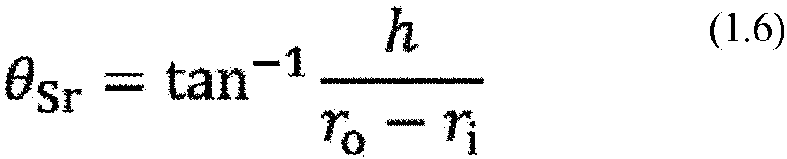
- As illustrated in
FIG. 16A , thefixer 41 placed in the above manner in theouter taper portion 33 can have the same length as the ridgeline EF of the conical surface of theouter taper portion 33 after forming, with the length of thefixer 41 in theouter taper portion 33 illustrated inFIG. 7 . The same applies to thefixer 41 in theinner taper portion 34. This allows, in addition to the fixed first fiber tows 51 to be displaceable relative to one another, the parts of the first fiber tows 51 restricted by thefixer 41 to be placed on the same ridgeline of the conical surface of theouter taper 33 after forming. This thus allows theouter taper portion 33 and theinner taper portion 34 to appropriately form into conical surfaces. - In this case, the
outer flange 38 and theinner flange 39 may have the same features as inEmbodiment 1. Theouter slits 23 and theinner slits 24 may also have the same features as inEmbodiment 1. -
FIG. 17 illustrates afiber preform 14 according to Embodiment 4. Thefiber preform 14 according to the present embodiment is manufactured using thefiber preform precursor 13 according toEmbodiment 3.FIGS. 18A to 18C are partial enlarged views of areas U1 to U3 inFIG. 17 . Like reference signs denote features common with the features in the above embodiments and are not described in detail. - As illustrated in
FIG. 17 , a portion of the base 21 including no fiber tow is cut off in the present embodiment. - As illustrated in
FIG. 18B , for example, the second fiber tows 52 in thecenter portion 31 are fixed with the water-insoluble fixing threads 57. As illustrated inFIGS. 18A and18C , the water-soluble fixing threads 56 fixing the first fiber tows 51 to the base 21 are removed in theouter taper portion 33 and theinner taper portion 34. As schematically illustrated inFIG. 15 , thefixer 41 may also be located on the water-soluble fixing threads 56. Although the water-soluble fixing threads 56 are removed with water during manufacture of thefiber preform 14, the water-soluble fixing threads 56 located under thefixer 41 may be left in thefiber preform 14. - With this structure, the first fiber tows 51 are displaceable relative to one another in the
outer taper portion 33 and theinner taper portion 34. However, with parts of the first fiber tows 51 fixed with thefixer 41, the first fiber tows 51 can remain unseparated from thebase 21. Thefiber preform 14 can thus have higher formability. This structure is particularly effective in forming a fiber preform into a shape with a curved surface. Theouter flange portion 38, theinner flange portion 39, theouter slits 23, theinner slits 24, and thefixer 41 in the present embodiment may have the same features as inEmbodiments outer taper portion 33 and theinner taper portion 34 to form into the conical surfaces more appropriately. - A method for manufacturing the
fiber preform 12 according to Embodiment 5 is described with reference to the drawings. - As illustrated in
FIG. 19 , the dashedouter slits 23 are formed in an area on the base 21 in which theouter taper portion 33 is to be located. Similarly, theinner slits 24 are formed in the base 21 in an area in which theinner taper portion 34 is to be located. - Subsequently, as illustrated in
FIG. 20 , the first fiber tows 51 are stitched onto the area in which theouter taper portion 33 is to be located with the water-soluble fixing threads 56 using a known automatic sewing machine or a known embroidering machine. Similarly, the first fiber tows 51 are stitched onto the area in which theinner taper portion 34 is to be located with the water-soluble fixing threads 56. - The second fiber tows 52 are then stitched onto areas of the
base 21 without the first fiber tows 51 with the water-insoluble fixing threads 57 using a known automatic sewing machine or a known embroidering machine. In the present embodiment, as illustrated inFIG. 21 , the second fiber tows 52 are stitched onto the areas in which thecenter portion 31, theside portions outer flange portion 38, and theinner flange portion 39 are to be located. - The
fixer 40 is then placed across the first fiber tows 51 as illustrated inFIG. 22 . More specifically, thethird fiber tow 53 is stitched onto the first fiber tows 51 with the water-insoluble fixing thread 58 using a known automatic sewing machine or a known embroidering machine. - The
fiber preform precursor 11 is thus manufactured. Theouter flange portion 38, theinner flange portion 39, theouter slits 23, theinner slits 24, or thefixer 40 may be formed to satisfy the conditions described inEmbodiment 1. - The water-soluble fixing threads in the
fiber preform precursor 11 are then removed with water. More specifically, thefiber preform precursor 11 is immersed in water to dissolve the water-soluble fixing threads. Thefiber preform precursor 11 may be sprayed with water to dissolve and remove the water-soluble fixing threads. Unnecessary portions of the base 21 may be cut off and removed. - With the above processes, the
fiber preform 12 can be manufactured. - With the method for manufacturing a fiber preform according to the present disclosure, parts of the fiber tows remain unseparated from the base and fixed to allow displacement of the fiber tows relative to one another. The fiber preform can thus have higher formability. Additionally, with the manufacturing method according to the present disclosure, the first fiber tows 51 are fixed with water-soluble fixing threads that are easily removable with water. The fiber preform with higher formability can thus be manufactured. Additionally, this method can eliminate creating a cutout in the fiber tows for higher formability and can avoid lowering the rigidity of the formed product.
- A method for manufacturing the
fiber preform 14 according to Embodiment 6 is described with reference to the drawings. - The processes of forming the
outer slits 23 and theinner slits 24, stitching the first fiber tows 51, and stitching the second fiber tows 52 are performed in the same manner as in Embodiment 5. Theouter flange portion 38, theinner flange portion 39, theouter slits 23, theinner slits 24, or thefixer 41 may be formed to satisfy the conditions described inEmbodiment - As illustrated in
FIG. 24 , thefixer 41 is then placed across the first fiber tows 51. More specifically, thefixer 41 is applied to the first fiber tows 51 fixed with the water-soluble fixing threads 56 using an applicator such as a dispenser to bond the first fiber tows 51 to thebase 21. When a material to be cured, such as an elastic adhesive, is used for thefixer 41, the process of curing is performed after applying. - The
fiber preform precursor 13 is thus manufactured. - The water-
soluble fixing threads 56 in thefiber preform precursor 13 are then removed with water. More specifically, thefiber preform precursor 13 is immersed in water to dissolve the water-soluble fixing threads 56. Thefiber preform precursor 13 may be sprayed with water to dissolve and remove the water-soluble fixing threads 56. The water-soluble fixing threads 56 under thefixer 41 may remain undissolved. Unnecessary portions of the base 21 may be cut off as appropriate. - With the above processes, the
fiber preform 14 can be manufactured. - With the method for manufacturing a fiber preform according to embodiments of the present disclosure, parts of the fiber tows remain unseparated from the base and fixed to allow displacement of the fiber tows relative to one another. The fiber preform can thus have higher formability. Additionally, with the manufacturing method according to the present embodiment, the first fiber tows 51 are fixed with water-soluble fixing threads that are easily removable with water. The fiber preform with higher formability can thus be manufactured. Additionally, this method can eliminate creating a cutout in the fiber tows for higher formability and can avoid lowering the rigidity of the formed product.
- The present disclosure is not limited to the above embodiments. For example, in
Embodiments outer flange portion 38, theinner flange portion 39, theouter slits 23, theinner slits 24, and thefixers - In the above embodiments, the fiber preform precursor and the fiber preform for a partial-disk sandwich panel with a central angle of 90° are illustrated. However, the present disclosure is not limited to the above structure. For example, the central angle or the shape may be changed. Either the
outer taper portion 33 or theinner taper portion 34, rather than both, may be included. For example, the fiber preform precursor or the fiber preform to form into a truncated cone may simply include theouter taper portion 33. The features of the above embodiments may be combined as appropriate. - The foregoing describes some example embodiments for explanatory purposes. Although the foregoing discussion has presented specific embodiments, persons skilled in the art will recognize that changes may be made in form and detail without departing from the broader spirit and scope of the invention. Accordingly, the specification and drawings are to be regarded in an illustrative rather than a restrictive sense. This detailed description, therefore, is not to be taken in a limiting sense, and the scope of the invention is defined only by the included claims, along with the full range of equivalents to which such claims are entitled.
-
- 11, 13
- Fiber preform precursor
- 12, 14
- Fiber preform
- 21
- Base
- 23
- Outer slit
- 24
- Inner slit
- 31
- Center portion
- 33
- Outer taper portion
- 34
- Inner taper portion
- 35, 36
- Side portion
- 38
- Outer flange portion
- 39
- Inner flange portion
- 40, 41
- Fixer
- 51
- First fiber tow
- 52
- Second fiber tow
- 53
- Third fiber tow
- 56
- Water-soluble fixing thread
- 57, 58
- Water-insoluble fixing thread
- 60
- Forming mold
- 61, 62
- Conical surface
Claims (12)
- A fiber preform, comprising:first fiber tows located in a first area on a base;a second fiber tow located in a second area on the base other than the first area, the second fiber tow being stitched onto the base with a water-insoluble fixing thread; anda fixer located across the first fiber tows to fix parts of the first fiber tows to the base, whereinthe fixer is a third fiber tow stitched onto the base with a water-insoluble fixing thread, or the fixer is a glue or an elastic adhesive,the first fiber tows are displaceable relative to one another, andthe first area is displaceable relative to the second area.
- The fiber preform according to claim 1, further comprising:an outer taper portion to be formed into a conical surface, whereinthe outer taper portion is located in the first area.
- The fiber preform according to claim 2, further comprising:a center portion located along an inner periphery of the outer taper portion; andan outer flange portion located along an outer periphery of the outer taper portion, whereinthe outer taper portion is to be formed into the conical surface by rotating the outer flange portion in a circumferential direction to be placed along a mold, andthe outer flange portion is rotated in a direction opposite to a direction in which the outer flange portion is to be rotated in forming, by a length equal to a height of an outer periphery of the center portion after forming.
- The fiber preform according to claim 2 or 3, whereinthe outer taper portion has an outer periphery centered on a point O with an outer diameter Ro and an inner periphery centered on the point O with an inner diameter Ri,the fiber preform further comprises a center portion located along the inner periphery of the outer taper portion, and the center portion has a height H at its outer periphery after forming, andthe base has a dashed slit in an area in which the outer taper portion is located, the slit extends on a line Dso from the outer periphery of the outer taper portion to the inner periphery of the outer taper portion, and the line Dso forms, with a line extending from the center O to a point at which the line Dso intersects with the inner periphery of the outer taper portion, an angle θSR defined by Formula 1.3:

- The fiber preform according to any one of claims 2 to 4, whereinthe outer taper portion has an outer periphery centered on a point O with an outer diameter Ro and an inner periphery centered on the point O with an inner diameter Ri,the fiber preform further comprises a center portion located along the inner periphery of the outer taper portion, and the center portion has a height H at its outer periphery after forming, andthe fixer extends on a line Dfo from the outer periphery of the outer taper portion to the inner periphery of the outer taper portion, and the line Dfo forms, with a line extending from the center O to a point at which the line Dfo intersects with the inner periphery of the outer taper portion, an angle θSR defined by Formula 1.5:

- The fiber preform according to any one of claims 1 to 5, further comprising:an inner taper portion to be formed into a conical surface, whereinthe inner taper portion is located in the first area.
- The fiber preform according to claim 6, further comprising:a center portion located along an outer periphery of the inner taper portion; andan inner flange portion located along an inner periphery of the inner taper portion, whereinthe inner taper portion is to be placed along a mold by rotating the inner flange in a circumferential direction, andthe inner flange portion is rotated in a direction opposite to a direction in which the inner flange portion is to be rotated in forming by a length equal to a height h of an inner periphery of the center portion after forming.
- The fiber preform according to claim 6 or 7, whereinthe inner taper portion has an outer periphery centered on a point O with an outer diameter ro and an inner periphery centered on the point O with an inner diameter r;,the fiber preform further comprises a center portion located along the outer periphery of the inner taper portion, and the center portion has a height h at its inner periphery inner taper portion after forming, andthe base has a dashed slit in an area in which the inner taper portion is located, the slit extends on a line Dsi from the outer periphery of the inner taper portion to the inner periphery of the inner taper portion, and the line Dsi forms, with a line extending from the center O to a point at which the line Dsi intersects with the outer periphery of the inner taper portion, an angle θSr defined by Formula 1.4:

- The fiber preform according to any one of claims 6 to 8, whereinthe inner taper portion has an outer periphery centered on a point O with an outer diameter ro and an inner periphery centered on the point O with an inner diameter r;,the fiber preform further comprises a center portion located along the outer periphery of the inner taper portion, and the center portion has a height h at its inner periphery after forming, andthe fixer extends on a line Dfi from the outer periphery of the inner taper portion to the inner periphery of the inner taper portion, and the line Dfi forms, with a line extending from the center O to a point at which the line Dfi intersects with the outer periphery of the inner taper portion, an angle θSr defined by Formula 1.6:

- The fiber preform according to any one of claims 1 to 9, whereinthe base has a dashed slit in the first area,the slit has a plurality of openings arranged linearly, andthe portions of the base between the plurality of openings adjacent to each other are cut through shear deformation of the base in forming to connect the plurality of openings with each other.
- A fiber preform precursor for manufacturing the fiber preform according to any one of claims 1 to 10, wherein
the first fiber tows are stitched onto the base with a water-soluble fixing thread. - A method for manufacturing a fiber preform, comprising:manufacturing a fiber preform precursor, the manufacturing includingstitching first fiber tows onto a first area of a base with a water-soluble fixing thread,stitching a second fiber tow onto a second area of the base other than the first area with a water-insoluble fixing thread, andplacing a fixer across the first fiber tows to fix parts of the first fiber tows to the base; anddissolving the water-soluble fixing thread in the fiber preform precursor with water to remove the water-soluble fixing thread, whereinthe fixer is a third fiber tow stitched onto the base with a water-insoluble fixing thread, or the fixer is a glue or an elastic adhesive,the first fiber tows are displaceable relative to one another, andthe first area is displaceable relative to the second area.
Applications Claiming Priority (1)
| Application Number | Priority Date | Filing Date | Title |
|---|---|---|---|
| PCT/JP2022/009552 WO2023166737A1 (en) | 2022-03-04 | 2022-03-04 | Fiber preform, fiber preform precursor, and method for manufacturing fiber preform |
Publications (2)
| Publication Number | Publication Date |
|---|---|
| EP4488021A1 true EP4488021A1 (en) | 2025-01-08 |
| EP4488021A4 EP4488021A4 (en) | 2025-04-16 |
Family
ID=87883457
Family Applications (1)
| Application Number | Title | Priority Date | Filing Date |
|---|---|---|---|
| EP22929881.5A Pending EP4488021A4 (en) | 2022-03-04 | 2022-03-04 | FIBER PREFORM, FIBER PREFORM PRECURSOR, AND METHOD FOR MANUFACTURING FIBER PREFORM |
Country Status (5)
| Country | Link |
|---|---|
| US (1) | US20250162277A1 (en) |
| EP (1) | EP4488021A4 (en) |
| JP (1) | JP7693087B2 (en) |
| CN (1) | CN118829531A (en) |
| WO (1) | WO2023166737A1 (en) |
Families Citing this family (1)
| Publication number | Priority date | Publication date | Assignee | Title |
|---|---|---|---|---|
| US20250282105A1 (en) * | 2024-03-07 | 2025-09-11 | United States Of America As Represented By The Administrator Of Nasa | Composite parts with stitching |
Family Cites Families (11)
| Publication number | Priority date | Publication date | Assignee | Title |
|---|---|---|---|---|
| DE10061028A1 (en) * | 2000-12-08 | 2002-06-20 | Eads Deutschland Gmbh | Process for producing multilayer TFP preforms using fusible fixing threads |
| DE102005034395B4 (en) * | 2005-07-22 | 2008-04-10 | Airbus Deutschland Gmbh | Process for the production of single or multilayer fiber preforms in the TFP process |
| DE102005034401B4 (en) * | 2005-07-22 | 2008-02-14 | Airbus Deutschland Gmbh | Process for the production of single or multilayer fiber preforms |
| DE102005034393B4 (en) * | 2005-07-22 | 2009-04-02 | Airbus Deutschland Gmbh | Process for the production of single or multilayer fiber preforms in the TFP process |
| EP2599614B1 (en) * | 2011-12-01 | 2016-03-02 | Techspace Aero S.A. | Method for manufacturing a preform and its use in the manufacture of a composite part |
| JP2014100911A (en) | 2012-10-25 | 2014-06-05 | Toray Ind Inc | Preform and production method of the same |
| EP3129203A1 (en) * | 2014-04-08 | 2017-02-15 | SABIC Global Technologies B.V. | Method of making a composite preform |
| JP6946666B2 (en) * | 2016-03-02 | 2021-10-06 | 東レ株式会社 | Reinforced fiber laminated sheet and fiber reinforced resin molded product |
| WO2018195074A2 (en) * | 2017-04-17 | 2018-10-25 | Coats Group Plc | Fiber preform and method of making the same |
| WO2019008444A1 (en) * | 2017-07-05 | 2019-01-10 | Coats Group Plc | Fiber preform of commingled fiber bundle for overmolding |
| US20210237316A1 (en) | 2020-01-31 | 2021-08-05 | Coats & Clark, Inc. | Fiber preform and method of making the same |
-
2022
- 2022-03-04 WO PCT/JP2022/009552 patent/WO2023166737A1/en not_active Ceased
- 2022-03-04 CN CN202280092894.4A patent/CN118829531A/en active Pending
- 2022-03-04 US US18/839,463 patent/US20250162277A1/en active Pending
- 2022-03-04 JP JP2024504329A patent/JP7693087B2/en active Active
- 2022-03-04 EP EP22929881.5A patent/EP4488021A4/en active Pending
Also Published As
| Publication number | Publication date |
|---|---|
| JP7693087B2 (en) | 2025-06-16 |
| JPWO2023166737A1 (en) | 2023-09-07 |
| EP4488021A4 (en) | 2025-04-16 |
| CN118829531A (en) | 2024-10-22 |
| US20250162277A1 (en) | 2025-05-22 |
| WO2023166737A1 (en) | 2023-09-07 |
Similar Documents
| Publication | Publication Date | Title |
|---|---|---|
| CA1287716C (en) | Resin transfer molding core, preform and process | |
| DE60105303T2 (en) | run-flat | |
| KR102465652B1 (en) | Method of Manufacturing Fiber Reinforced Pressure Tank with Pole Cap Reinforcement | |
| EP4488021A1 (en) | Fiber preform, fiber preform precursor, and method for manufacturing fiber preform | |
| RU2401740C2 (en) | Method of producing one- or multilayer fibrous workpiece in compliance with tfp-process | |
| RU2425748C2 (en) | Procedure for fabrication of fibrous layer at production of work piece of composite part | |
| EP2502733B1 (en) | Dry preform, annular structure made of a composite material, and manufacturing method for the annular structure | |
| WO2011111564A1 (en) | Method for producing reinforcement fiber preform, and reinforcement fiber preform | |
| DE102005045178B3 (en) | Plastics drum assembly, for a front loading horizontal drum washing machine, has a metal hub bonded into the plastics mass with embedded reinforcement fiber strands extending radially from the hub to the end wall | |
| DE2533876A1 (en) | THREAD WRAPPED BOTTLE AND METHOD OF MANUFACTURING IT | |
| US4749422A (en) | Process for preparing a fiber-reinforced plastic structure having branching points | |
| JP2001030361A (en) | Method for molding preform | |
| JPH09117968A (en) | Pipe material and manufacturing method thereof | |
| EP3176295A1 (en) | Combined filament yarn and manufacturing method thereof | |
| JPH01141723A (en) | Method of fixing connecting body to product composed of composite product and connecting body used for said method | |
| EP0667668A2 (en) | Method of manufacturing a fibre reinforced airgap hood | |
| US20080277047A1 (en) | Frp honeycomb structure and method for manufacturing the same | |
| US20220242062A1 (en) | Fibre-Reinforced Composite Tubular Shafts and Manufacture Thereof | |
| KR101232812B1 (en) | Drawing type rod | |
| JP5594872B2 (en) | Colored fiber reinforced composite | |
| JPH0734944Y2 (en) | Reinforcement material for composite disc-shaped articles | |
| JP3430982B2 (en) | Preform manufacturing system | |
| JP3156130B2 (en) | Composite structural member having high bending strength and manufacturing method | |
| JP3162143B2 (en) | Method of manufacturing fiber reinforced resin pipe joint | |
| KR100443188B1 (en) | Laminated pipe of fishing rod and fabrication method thereof |
Legal Events
| Date | Code | Title | Description |
|---|---|---|---|
| STAA | Information on the status of an ep patent application or granted ep patent |
Free format text: STATUS: THE INTERNATIONAL PUBLICATION HAS BEEN MADE |
|
| PUAI | Public reference made under article 153(3) epc to a published international application that has entered the european phase |
Free format text: ORIGINAL CODE: 0009012 |
|
| STAA | Information on the status of an ep patent application or granted ep patent |
Free format text: STATUS: REQUEST FOR EXAMINATION WAS MADE |
|
| 17P | Request for examination filed |
Effective date: 20240809 |
|
| AK | Designated contracting states |
Kind code of ref document: A1 Designated state(s): AL AT BE BG CH CY CZ DE DK EE ES FI FR GB GR HR HU IE IS IT LI LT LU LV MC MK MT NL NO PL PT RO RS SE SI SK SM TR |
|
| A4 | Supplementary search report drawn up and despatched |
Effective date: 20250319 |
|
| RIC1 | Information provided on ipc code assigned before grant |
Ipc: B29B 11/16 20060101AFI20250313BHEP |
|
| DAV | Request for validation of the european patent (deleted) | ||
| DAX | Request for extension of the european patent (deleted) | ||
| STAA | Information on the status of an ep patent application or granted ep patent |
Free format text: STATUS: EXAMINATION IS IN PROGRESS |
|
| 17Q | First examination report despatched |
Effective date: 20260306 |