EP4487988A1 - Energy storage device, welding method for energy storage device, and electricity-consumption device - Google Patents
Energy storage device, welding method for energy storage device, and electricity-consumption device Download PDFInfo
- Publication number
- EP4487988A1 EP4487988A1 EP24179111.0A EP24179111A EP4487988A1 EP 4487988 A1 EP4487988 A1 EP 4487988A1 EP 24179111 A EP24179111 A EP 24179111A EP 4487988 A1 EP4487988 A1 EP 4487988A1
- Authority
- EP
- European Patent Office
- Prior art keywords
- end cap
- main body
- current collector
- peripheral side
- housing
- Prior art date
- Legal status (The legal status is an assumption and is not a legal conclusion. Google has not performed a legal analysis and makes no representation as to the accuracy of the status listed.)
- Pending
Links
Images






Classifications
-
- B—PERFORMING OPERATIONS; TRANSPORTING
- B23—MACHINE TOOLS; METAL-WORKING NOT OTHERWISE PROVIDED FOR
- B23K—SOLDERING OR UNSOLDERING; WELDING; CLADDING OR PLATING BY SOLDERING OR WELDING; CUTTING BY APPLYING HEAT LOCALLY, e.g. FLAME CUTTING; WORKING BY LASER BEAM
- B23K26/00—Working by laser beam, e.g. welding, cutting or boring
- B23K26/20—Bonding
- B23K26/21—Bonding by welding
- B23K26/24—Seam welding
- B23K26/28—Seam welding of curved planar seams
- B23K26/282—Seam welding of curved planar seams of tube sections
-
- B—PERFORMING OPERATIONS; TRANSPORTING
- B23—MACHINE TOOLS; METAL-WORKING NOT OTHERWISE PROVIDED FOR
- B23K—SOLDERING OR UNSOLDERING; WELDING; CLADDING OR PLATING BY SOLDERING OR WELDING; CUTTING BY APPLYING HEAT LOCALLY, e.g. FLAME CUTTING; WORKING BY LASER BEAM
- B23K26/00—Working by laser beam, e.g. welding, cutting or boring
- B23K26/20—Bonding
- B23K26/21—Bonding by welding
-
- B—PERFORMING OPERATIONS; TRANSPORTING
- B23—MACHINE TOOLS; METAL-WORKING NOT OTHERWISE PROVIDED FOR
- B23K—SOLDERING OR UNSOLDERING; WELDING; CLADDING OR PLATING BY SOLDERING OR WELDING; CUTTING BY APPLYING HEAT LOCALLY, e.g. FLAME CUTTING; WORKING BY LASER BEAM
- B23K26/00—Working by laser beam, e.g. welding, cutting or boring
- B23K26/70—Auxiliary operations or equipment
- B23K26/702—Auxiliary equipment
-
- H—ELECTRICITY
- H01—ELECTRIC ELEMENTS
- H01M—PROCESSES OR MEANS, e.g. BATTERIES, FOR THE DIRECT CONVERSION OF CHEMICAL ENERGY INTO ELECTRICAL ENERGY
- H01M10/00—Secondary cells; Manufacture thereof
- H01M10/04—Construction or manufacture in general
- H01M10/0422—Cells or battery with cylindrical casing
-
- H—ELECTRICITY
- H01—ELECTRIC ELEMENTS
- H01M—PROCESSES OR MEANS, e.g. BATTERIES, FOR THE DIRECT CONVERSION OF CHEMICAL ENERGY INTO ELECTRICAL ENERGY
- H01M10/00—Secondary cells; Manufacture thereof
- H01M10/04—Construction or manufacture in general
- H01M10/0431—Cells with wound or folded electrodes
-
- H—ELECTRICITY
- H01—ELECTRIC ELEMENTS
- H01M—PROCESSES OR MEANS, e.g. BATTERIES, FOR THE DIRECT CONVERSION OF CHEMICAL ENERGY INTO ELECTRICAL ENERGY
- H01M50/00—Constructional details or processes of manufacture of the non-active parts of electrochemical cells other than fuel cells, e.g. hybrid cells
- H01M50/10—Primary casings; Jackets or wrappings
- H01M50/102—Primary casings; Jackets or wrappings characterised by their shape or physical structure
- H01M50/107—Primary casings; Jackets or wrappings characterised by their shape or physical structure having curved cross-section, e.g. round or elliptic
-
- H—ELECTRICITY
- H01—ELECTRIC ELEMENTS
- H01M—PROCESSES OR MEANS, e.g. BATTERIES, FOR THE DIRECT CONVERSION OF CHEMICAL ENERGY INTO ELECTRICAL ENERGY
- H01M50/00—Constructional details or processes of manufacture of the non-active parts of electrochemical cells other than fuel cells, e.g. hybrid cells
- H01M50/10—Primary casings; Jackets or wrappings
- H01M50/147—Lids or covers
- H01M50/148—Lids or covers characterised by their shape
- H01M50/15—Lids or covers characterised by their shape for prismatic or rectangular cells
-
- H—ELECTRICITY
- H01—ELECTRIC ELEMENTS
- H01M—PROCESSES OR MEANS, e.g. BATTERIES, FOR THE DIRECT CONVERSION OF CHEMICAL ENERGY INTO ELECTRICAL ENERGY
- H01M50/00—Constructional details or processes of manufacture of the non-active parts of electrochemical cells other than fuel cells, e.g. hybrid cells
- H01M50/10—Primary casings; Jackets or wrappings
- H01M50/147—Lids or covers
- H01M50/148—Lids or covers characterised by their shape
- H01M50/152—Lids or covers characterised by their shape for cells having curved cross-section, e.g. round or elliptic
-
- H—ELECTRICITY
- H01—ELECTRIC ELEMENTS
- H01M—PROCESSES OR MEANS, e.g. BATTERIES, FOR THE DIRECT CONVERSION OF CHEMICAL ENERGY INTO ELECTRICAL ENERGY
- H01M50/00—Constructional details or processes of manufacture of the non-active parts of electrochemical cells other than fuel cells, e.g. hybrid cells
- H01M50/10—Primary casings; Jackets or wrappings
- H01M50/147—Lids or covers
- H01M50/166—Lids or covers characterised by the methods of assembling casings with lids
- H01M50/169—Lids or covers characterised by the methods of assembling casings with lids by welding, brazing or soldering
-
- H—ELECTRICITY
- H01—ELECTRIC ELEMENTS
- H01M—PROCESSES OR MEANS, e.g. BATTERIES, FOR THE DIRECT CONVERSION OF CHEMICAL ENERGY INTO ELECTRICAL ENERGY
- H01M50/00—Constructional details or processes of manufacture of the non-active parts of electrochemical cells other than fuel cells, e.g. hybrid cells
- H01M50/50—Current conducting connections for cells or batteries
- H01M50/531—Electrode connections inside a battery casing
-
- H—ELECTRICITY
- H01—ELECTRIC ELEMENTS
- H01M—PROCESSES OR MEANS, e.g. BATTERIES, FOR THE DIRECT CONVERSION OF CHEMICAL ENERGY INTO ELECTRICAL ENERGY
- H01M50/00—Constructional details or processes of manufacture of the non-active parts of electrochemical cells other than fuel cells, e.g. hybrid cells
- H01M50/50—Current conducting connections for cells or batteries
- H01M50/531—Electrode connections inside a battery casing
- H01M50/533—Electrode connections inside a battery casing characterised by the shape of the leads or tabs
-
- H—ELECTRICITY
- H01—ELECTRIC ELEMENTS
- H01M—PROCESSES OR MEANS, e.g. BATTERIES, FOR THE DIRECT CONVERSION OF CHEMICAL ENERGY INTO ELECTRICAL ENERGY
- H01M50/00—Constructional details or processes of manufacture of the non-active parts of electrochemical cells other than fuel cells, e.g. hybrid cells
- H01M50/50—Current conducting connections for cells or batteries
- H01M50/531—Electrode connections inside a battery casing
- H01M50/536—Electrode connections inside a battery casing characterised by the method of fixing the leads to the electrodes, e.g. by welding
-
- H—ELECTRICITY
- H01—ELECTRIC ELEMENTS
- H01M—PROCESSES OR MEANS, e.g. BATTERIES, FOR THE DIRECT CONVERSION OF CHEMICAL ENERGY INTO ELECTRICAL ENERGY
- H01M50/00—Constructional details or processes of manufacture of the non-active parts of electrochemical cells other than fuel cells, e.g. hybrid cells
- H01M50/50—Current conducting connections for cells or batteries
- H01M50/531—Electrode connections inside a battery casing
- H01M50/538—Connection of several leads or tabs of wound or folded electrode stacks
-
- H—ELECTRICITY
- H01—ELECTRIC ELEMENTS
- H01M—PROCESSES OR MEANS, e.g. BATTERIES, FOR THE DIRECT CONVERSION OF CHEMICAL ENERGY INTO ELECTRICAL ENERGY
- H01M50/00—Constructional details or processes of manufacture of the non-active parts of electrochemical cells other than fuel cells, e.g. hybrid cells
- H01M50/50—Current conducting connections for cells or batteries
- H01M50/543—Terminals
- H01M50/564—Terminals characterised by their manufacturing process
- H01M50/566—Terminals characterised by their manufacturing process by welding, soldering or brazing
-
- H—ELECTRICITY
- H01—ELECTRIC ELEMENTS
- H01M—PROCESSES OR MEANS, e.g. BATTERIES, FOR THE DIRECT CONVERSION OF CHEMICAL ENERGY INTO ELECTRICAL ENERGY
- H01M50/00—Constructional details or processes of manufacture of the non-active parts of electrochemical cells other than fuel cells, e.g. hybrid cells
- H01M50/60—Arrangements or processes for filling or topping-up with liquids; Arrangements or processes for draining liquids from casings
- H01M50/609—Arrangements or processes for filling with liquid, e.g. electrolytes
- H01M50/627—Filling ports
-
- B—PERFORMING OPERATIONS; TRANSPORTING
- B23—MACHINE TOOLS; METAL-WORKING NOT OTHERWISE PROVIDED FOR
- B23K—SOLDERING OR UNSOLDERING; WELDING; CLADDING OR PLATING BY SOLDERING OR WELDING; CUTTING BY APPLYING HEAT LOCALLY, e.g. FLAME CUTTING; WORKING BY LASER BEAM
- B23K2101/00—Articles made by soldering, welding or cutting
- B23K2101/36—Electric or electronic devices
-
- Y—GENERAL TAGGING OF NEW TECHNOLOGICAL DEVELOPMENTS; GENERAL TAGGING OF CROSS-SECTIONAL TECHNOLOGIES SPANNING OVER SEVERAL SECTIONS OF THE IPC; TECHNICAL SUBJECTS COVERED BY FORMER USPC CROSS-REFERENCE ART COLLECTIONS [XRACs] AND DIGESTS
- Y02—TECHNOLOGIES OR APPLICATIONS FOR MITIGATION OR ADAPTATION AGAINST CLIMATE CHANGE
- Y02E—REDUCTION OF GREENHOUSE GAS [GHG] EMISSIONS, RELATED TO ENERGY GENERATION, TRANSMISSION OR DISTRIBUTION
- Y02E60/00—Enabling technologies; Technologies with a potential or indirect contribution to GHG emissions mitigation
- Y02E60/10—Energy storage using batteries
Definitions
- the disclosure relates to the field of energy storage technologies, and in particular to an energy storage device, a welding method for an energy storage device, and an electricity-consumption device.
- a secondary cell also known as a rechargeable cell or a storage cell, refers to a cell that can be charged after discharge to activate active substance of the cell for reuse. Since the secondary cell is reusable, the secondary cell gradually becomes a main power source for electricity-consumption devices. As the demand for the secondary cell gradually increases, people have increasingly higher requirements for various performances of the secondary cell, especially for the energy density per unit volume of the cell. However, for a cylindrical secondary cell, a gap defined between a wound electrode assembly and an end cap at one side of the cell and a gap defined between the wound electrode assembly and an end cap at the other side of the cell are key factors for restricting the energy density per unit volume of the cell.
- the disclosure provides an energy storage device, a welding method for an energy storage device, and an electricity-consumption device.
- a current collector of the energy storage device is welded to a peripheral side surface of an end cap and a peripheral side surface of a housing, thereby improving a strength of connection among the end cap, the current collector, and the housing.
- an energy storage device in a first aspect of the disclosure, includes an end cap, a housing, and a current collector arranged between the end cap and the housing.
- An outer peripheral side surface of the end cap is flush with an outer peripheral side surface of the housing.
- the current collector includes a main body and a welding portion. The main body and the welding portion are integrally formed.
- the main body has a first surface and a second surface facing away from the first surface.
- the end cap is connected to the first surface of the main body, the housing is connected to the second surface of the main body, and the welding portion is connected to the outer peripheral side surface of the end cap, the outer peripheral side surface of the housing, and an outer peripheral side surface of the main body.
- the current collector satisfies one of the following: the outer peripheral side surface of the main body is flush with both the outer peripheral side surface of the end cap and the outer peripheral side surface of the housing, in a radial direction of the current collector; and the outer peripheral side surface of the main body protrudes from both the outer peripheral side surface of the end cap and the outer peripheral side surface of the housing, in the radial direction of the current collector.
- the welding portion protrudes from the end cap by a width L1, where the width L1 satisfies: 0.05mm ⁇ L1 ⁇ 1.45mm; and the welding portion protrudes from the housing by a width L2, where the width L2 satisfies: 0.05mm ⁇ L2 ⁇ 1.45mm.
- an electricity-consumption device in a second aspect of the disclosure, includes a device body and the energy storage device provided in the first aspect of the disclosure, where the energy storage device is configured to power the device body.
- a welding method for an energy storage device includes the following. Provide an end cap, a housing, and a current collector. Make the end cap abut against a surface of the current collector and make the housing abut against a surface of the current collector facing away from the end cap, and expose an outer peripheral side surface of the current collector. Perform circumferential laser welding on an outer peripheral side of the current collector to fixedly connect the current collector to both the end cap and the housing, where the current collector subject to the welding includes a main body and a welding portion. The main body and the welding portion are integrally formed.
- the main body has a first surface and a second surface facing away from the first surface, the end cap is connected to the first surface of the main body, and the housing is connected to the second surface of the main body.
- the welding portion is connected to an outer peripheral side surface of the end cap, an outer peripheral side surface of the housing, and an outer peripheral side surface of the main body.
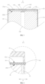
- FIG. 1 is a schematic structural view of an energy storage device provided in an embodiment of the disclosure.
- FIG. 2 is a structural exploded view of an energy storage device provided in an embodiment of the disclosure.
- FIG. 3 is cross-sectional view 1 of the embodiment of FIG. 1 , taken along line A-A.
- FIG. 4 is partially enlarged view 1 of FIG. 3 .
- FIG. 5 is partially enlarged view 2 of FIG. 3 .
- FIG. 6 is partially enlarged view 3 of FIG. 3 .
- FIG. 7 is partially enlarged view 4 of FIG. 3 .
- FIG. 8 is partially enlarged view 5 of FIG. 3 .
- FIG. 9 is partially enlarged view 6 of FIG. 3 .
- An energy storage device 1 is provided in the disclosure.
- a current collector 13 of the energy storage device 1 is welded to both a peripheral side surface of an end cap 11 and a peripheral side surface of a housing 12, so that a strength of connection among the end cap 11, the current collector 13, and the housing 12 may be improved.
- the energy storage device 1 may be but is not limited to a lithium-ion secondary cell, a lithium-ion primary cell, a lithium sulfur cell, a sodium lithium-ion cell, a sodium-ion cell, a magnesium-ion cell, etc.
- the energy storage device 1 provided in the embodiment includes the end cap 11, the housing 12, and the current collector 13 arranged between the end cap 11 and the housing 12.
- the current collector 13 includes a main body 131 and a welding portion 132.
- the main body 131 and the welding portion 132 are integrally formed.
- the main body 131 has a first surface 131a and a second surface 131b facing away from the first surface 131a.
- the end cap 11 is connected to the first surface 131a of the main body 131
- the housing 12 is connected to the second surface 131b of the main body 131.
- the welding portion 132 is connected to an outer peripheral side surface of the end cap 11, an outer peripheral side surface of the housing 12, and an outer peripheral side surface of the main body 131.
- the energy storage device 1 provided in the embodiment includes the end cap 11, where the end cap 11 is electrically connected to the current collector 13, and is used to fix and protect other components.
- the end cap 11 is connected to the current collector 13.
- the end cap 11 is partially welded to the current collector 13.
- the end cap 11 partially abuts against the current collector 13.
- the end cap 11 may be but is not limited to circular, rectangular, cap-shaped, etc.
- the end cap 11 may be a positive end cap 11 or a negative end cap 11.
- the end cap 11 includes an explosion-proof valve 111.
- the explosion-proof valve 111 is used to exhaust gas generated inside the energy storage device 1 to prevent explosion, thereby improving the safety of the energy storage device 1.
- the end cap 11 includes a second liquid-injection hole 112 for injection of electrolyte.
- the second liquid-injection hole 112 is defined on the center of the end cap 11.
- the energy storage device 1 provided in the embodiment further includes the housing 12.
- the housing 12 is used to accommodate, fix, and protect other components.
- the housing 12 is connected to the current collector 13.
- the housing 12 is partially welded to the current collector 13.
- the housing 12 partially abuts against the current collector 13.
- a material of the housing 12 may be a metal material such as aluminum, copper, or alloy.
- the housing 12 may be but is not limited to circular, rectangular, etc.
- the shape of the housing 12 is matched with the shape of the end cap 11, or the housing 12 has the same shape as the end cap 11.
- the energy storage device 1 further includes an electrode assembly 14.
- the housing 12 defines an accommodating cavity 121, and the electrode assembly 14 is arranged in the accommodating cavity 121.
- the energy storage device 1 provided in the embodiment further includes the current collector 13.
- the current collector 13 is electrically connected to the end cap 11, the housing 12, and the electrode assembly 14.
- the end cap 11 is welded to a surface of the current collector 13, and the housing 12 is welded to another surface of the current collector 13 facing away from the end cap 11.
- the current collector 13 includes the main body 131 and the welding portion 132, and the main body 131 and the welding portion 132 are integrally formed.
- the main body 131 may be understood as a portion of the current collector 13 that is not changed before and after welding.
- the welding portion 132 may be understood as a portion of the current collector 13 welded to both the end cap 11 and the housing 12, formed after the current collector 13 is subject to welding.
- the welding portion 132 is a welding seam formed by cooling and solidification of a molten metal after welding.
- an outer side surface of the main body 131 and an outer side surface of the welding portion 132 may both be a flat surface or a curved surface, which is not limited in the disclosure.
- the main body 131 and the welding portion 132 are marked with different patterns in FIG. 7 to FIG. 9 .
- the main body 131 and the welding portion 132 are integrally formed, as illustrated in FIG. 4 to FIG. 6 .
- the first surface 131a of the main body 131 is connected to the end cap 11. At least part of the end cap 11 abuts against the first surface 131a of the main body 131. For example, a surface of the end cap 11 facing the current collector 13 abuts against the first surface 131a.
- a part of the surface of the end cap 11 facing the current collector 13 abuts against the first surface 131a, and another part of the surface of the end cap 11 facing the current collector 13 abuts against the welding portion 132.
- At least part of the housing 12 abuts against the second surface 131b of the main body 131.
- a surface of the housing 12 facing the current collector 13 abuts against the second surface 131b.
- the welding portion 132 is connected to the outer peripheral side surface of the main body 131, and the outer peripheral side surface of the main body 131 is connected to both the first surface 131a and the second surface 131b.
- the welding portion 132 is further connected to both the end cap 11 and the housing 12.
- the welding portion 132 is connected to an outer peripheral side of the housing 12.
- the welding portion 132 is connected to an outer peripheral side of the end cap 11.
- the welding portion 132 is connected to the surface of the housing 12 facing the current collector 13.
- the welding portion 132 is connected to the surface of the end cap 11 facing the current collector 13.
- the welding portion 132 is the portion of the current collector 13 that is welded to the end cap 11 and the housing 12, formed after the current collector 13 is subject to welding, and thus the welding portion 132 may be connected to the end cap 11 and the housing 12 in various ways.
- the above mentioned connection between the welding portion 132 and the end cap 11 and between the welding portion 132 and the housing 12 may exist either alone or in various combinations with each other.
- the current collector 13 in the embodiment does not include a protrusion structure facing the end cap 11.
- the protrusion structure herein is a protrusion that is used for welding the current collector 13 to the end cap 11 in the related art.
- the current collector 13 defines a first liquid-injection hole 133 for injection of electrolyte.
- the first liquid-injection hole 133 is defined on the center of the current collector 13.
- the first liquid-injection hole 133 is arranged facing away from the second liquid-injection hole 112.
- the current collector 13 may be but is not limited to circular, rectangular, and the like.
- the current collector 13, the housing 12, and the end cap 11 are matched with each other in shape.
- the current collector 13, the housing 12, and the end cap 11 have the same shape.
- the current collector 13 is a positive current collector 13 or a negative current collector 13.
- the current collector 13 is the positive current collector 13; in the case where the end cap 11 is a negative end cap 11, the current collector 13 is the negative current collector 13.
- the end cap 11 is connected to the first surface 131a of the main body 131
- the housing 12 is connected to the second surface 131b of the main body 131
- the welding portion 132 is connected to the outer peripheral side surface of the main body 131
- the end cap 11, and the housing 12 and the welding portion 132 is connected to the peripheral side surface of the end cap 11 and the peripheral side surface of the housing 12.
- a welding region between the end cap 11 and the current collector 13 includes the welding portion 132 of the current collector 13 around the peripheral side surface of the end cap 11, and a portion of the outer peripheral side surface of the end cap 11 corresponding to the welding portion 132.
- the electrical connection region between the end cap 11 and the current collector 13 is expanded to include an outer-diameter portion of the end cap 11.
- the welding region between the end cap 11 and the current collector 13 is enlarged and the electrical connection region for the end cap 11 and the current collector 13 is enlarged, so that a current-flow through capability(i.e., a capability of allowing current to flow through) between the end cap 11 and the current collector 13 may be improved, thereby reducing or even avoiding easy-heating in the case where current converges in the welding region, and accordingly improving the strength of connection between the end cap 11 and the current collector 13.
- the current-flow through capability between the end cap 11 and the current collector 13 refers to a current-flow through capability of a current path between the end cap 11 and the current collector 13.
- the housing 12 has two dimensions in a radial direction, where one is a distance between two opposite positions of an outer peripheral side wall of the housing 12 (i.e., the outer diameter) and the other is a distance between two opposite positions of an inner peripheral side wall of the housing 12 (i.e., the inner diameter).
- the outer and inner diameters referred to hereinafter in the disclosure, which will not be repeated in the disclosure.
- the current collector 13 provided in the embodiment is arranged between and welded to the end cap 11 and the housing 12, the main body 131 is connected to both a surface of the end cap 11 facing the housing 12 and a surface of the housing 12 facing the end cap 11, and the welding portion 132 is connected to the peripheral side surface of the end cap 11 and the peripheral side surface of the housing 12. In the case where the energy storage device 1 falls, the current collector 13 tends to move away from the end cap 11 under the action of inertia.
- the current collector 13 may be prevented from moving in a direction away from the end cap 11 by abutting against the housing 12 under the action of the structural strength of the current collector 13, thereby further improving the strength of connection among the current collector 13, the housing 12, and the end cap 11, in other words, improving the structural strength among the current collector 13, the housing 12, and the end cap 11, and thus reducing the possibility of liquid leakage.
- the wound electrode assembly 14 inside the cell drives the positive current collector 13 to move away from the positive end cap 11 under the action of inertia
- the positive current collector 13 since the positive current collector 13 directly abuts against the housing 12, the positive current collector 13 may be prevented from further moving towards the ground by abutting against the housing 12 under the action of the structural strength of the positive current collector 13. In this way, the structural strength of the welding region among the current collector 13, the housing 12, and the end cap 11 is further improved.
- the current collector 13 is arranged between the end cap 11 and the housing 12 and is welded to the peripheral side surface of the end cap 11 and the peripheral side surface of the housing 12, and thus the welding region between the end cap 11 and the current collector 13 may be enlarged, thereby improving the current-flow through capability between the end cap 11 and the current collector 13, and accordingly improving the strength of connection among the end cap 11, the current collector 13, and the housing 12.
- FIG. 10 is partially enlarged view 7 of FIG. 3 .
- FIG. 11 is partially enlarged view 8 of FIG. 3 .
- FIG. 12 is partially enlarged view 9 of FIG. 3 .
- FIG. 13 is a cross-sectional view of a current collector, an end cap, and a housing provided in the embodiment of FIG. 1 , taken along line A-A, the current collector, the end cap, and the housing being not welded together. It may be noted that, in order to more clearly indicate the main body 131 and the welding portion 132, the main body 131 and the welding portion 132 are marked with different patterns in FIG. 7 to FIG. 12 . However, in actual production, the main body 131 and the welding portion 132 are integrally formed, as illustrated in FIG. 4 to FIG. 6 .
- the current collector 13 satisfies one of the following: the outer peripheral side surface of the main body 131 is flush with the outer peripheral side surface of the end cap 11 and/or the outer peripheral side surface of the main body 131 is flush with the outer peripheral side surface of the housing 12, in a radial direction of the current collector 13 (direction D in FIG. 7 ); and the outer peripheral side surface of the main body 131 protruding from the outer peripheral side surface of the end cap 11 and/or the outer peripheral side surface of the housing 12, in the radial direction of the current collector 13 (direction D in FIG. 10 ).
- At least part of the outer peripheral side surface of the main body 131 is flush with the outer peripheral side surface of the end cap 11.
- at least part of the outer peripheral side surface of the main body 131 is flush with the outer peripheral side surface of the housing 12.
- at least part of the outer peripheral side surface of the main body 131 protrudes from the outer peripheral side surface of the end cap 11.
- at least part of the outer peripheral side surface of the main body 131 protrudes from the outer peripheral side surface of the housing 12.
- the main body 131 is flush with or even protrudes from the end cap 11 and/or the housing 12.
- the radial dimension of the main body 131 is equal to or greater than the radial dimension of the outer peripheral side of the end cap 11; and/or, the radial dimension of the main body 131 is equal to or greater than the radial dimension of the outer peripheral side of the housing 12.
- the welding portion 132 is connected to the outer peripheral side of the main body 131, so the radial dimension of the current collector 13 is greater than both the radial dimension of the outer peripheral side of the end cap 11 and the radial dimension of the outer peripheral side of the housing 12, or the diameter of the current collector 13 is slightly greater than both the diameter of the end cap 11 and the diameter of the housing 12.
- the end cap 11, the current collector 13, and the housing 12 may be placed horizontally after assembly, and then welding is performed once on a side wall of the energy storage device 1 to achieve shaping.
- the current collector 13 may be arranged protruding from the end cap 11 and the housing 12. It may also be understood that the current collector 13 has a welding convex ring protruding from both an outer side wall of the end cap 11 and an outer side wall of the housing 12, where the welding convex ring is used for welding.
- the housing 12 is uniformly rotated by a full turn to complete welding.
- the welding convex ring is firstly heated and melted to achieve "top melting". That is, the welding convex ring melted flows to two sides under the action of gravity to fill the gap between the end cap 11 and the current collector 13 or the gap between the housing 12 and the current collector 13, then the welding convex ring melted is fused together with the end cap 11 and the housing 12 that are melted subsequently, thereby further enhancing the structural strength and airtightness of the welding region.
- the welding convex ring may be melted to a solder.
- requirements for a machining precision of a joint surface of the end cap 11 and a joint surface of the housing 12 are reduced, and thus the manufacturing cost of components of the energy storage device 1 is further reduced.
- the current collector 13 protrudes from both the end cap 11 and the housing 12 by a width L3, where the width L3 satisfies: 0.25mm ⁇ L3 ⁇ 2mm. It may also be understood that, the welding convex ring protrudes from both the end cap 11 and the housing 12 by the width L3, where the width L3 satisfies: 0.25mm ⁇ L3 ⁇ 2mm.
- the width L3 refers to a distance from an outer peripheral side wall of the current collector 13 to an outer peripheral side wall of the end cap 11, or a distance from the outer peripheral side wall of the current collector 13 to the outer peripheral side wall of the housing 12.
- the width L3 may be equal to but is not limited to 0.25mm, 0.3mm, 0.35mm, 0.4mm, 0.45mm, 0.5mm, 0.55mm, 0.6mm, 0.65mm, 0.7mm, 0.75mm, 0.8mm, 0.85mm, 0.9mm, 0.95mm, 1mm, 1.1mm, 1.2mm, 1.3mm, 1.4mm, 1.5mm, 1.6mm, 1.7mm, 1.8mm, 1.9mm, 2mm, and the like.
- the width L3 satisfies 0.25mm ⁇ L3 ⁇ 2mm, not only requirements for the machining precision of the joint surface of the end cap 11 and the joint surface of the housing 12 may be reduced and the structural strength and airtightness of the welding region may be enhanced, but also the time for welding may be reduced, the efficiency of welding may be improved, and the manufacturing cost may be reduced.
- the width L3 is too small, it is not conducive to aligning the laser welding head with the welding convex ring, and thus requirements for the machining precision of the joint surface of the end cap 11 and the joint surface of the housing 12 may be increased.
- the welding portion 132 protrudes from the end cap 11 by a width L1, and the width L1 satisfies: 0.05mm ⁇ L1 ⁇ 1.45mm; and/or the welding portion 132 protrudes from the end cap 11 by a width L2, and the width L2 satisfies: 0.05mm ⁇ L2 ⁇ 1.45mm.
- the width L1 refers to a distance from an outer peripheral side wall of the welding portion 132 to the outer peripheral side wall of the end cap 11, or refers to a height at which the welding portion 132 protrudes from the outer peripheral side wall of the end cap 11.
- the width L2 refers to a distance from the outer peripheral side wall of the welding portion 132 to the outer peripheral side wall of the housing 12, or refers to a height at which the welding portion 132 protrudes from the outer peripheral side wall of the housing 12.
- the width L1 and L2 may both be equal to but are not limited to 0.05mm, 0.10mm, 0.15mm, 0.20mm, 0.25mm, 0.3mm, 0.35mm, 0.4mm, 0.45mm, 0.5mm, 0.55mm, 0.6mm, 0.65mm, 0.7mm, 0.75mm, 0.8mm, 0.85mm, 0.9mm, 0.95mm, 1mm, 1.05mm, 1.1mm, 1.15mm, 1.2mm, 1.25mm, 1.3mm, 1.35mm, 1.4mm, 1.45mm, and the like.
- the width L1 satisfies 0.05mm ⁇ L1 ⁇ 1.45mm.
- the width L1 is greater than or equal to 0.05mm
- the height at which the welding portion 132 protrudes from a side wall surface of the end cap 11 is greater than or equal to 0.05mm.
- the welding seam formed after welding does not protrude excessively from the side wall surface of the end cap 11, so that in subsequent plastically encapsulation of an insulation film, the insulation film is not prone to wrinkle, and an interference between the energy storage device 1 and an accommodating groove of a module may not easily occur during assembly of the energy storage device 1 and the module, so that the energy storage device 1 may be placed smoothly.
- the width L2 satisfies 0.05mm ⁇ L2 ⁇ 1.45mm.
- the width L2 is greater than or equal to 0.05mm
- the height at which the welding portion 132 protrudes from a side wall surface of the housing 12 is greater than or equal to 0.05mm.
- the welding seam formed after welding does not protrude excessively from the side wall surface of the housing 12, so that in subsequent plastically encapsulation of an insulation film, the insulation film is not prone to wrinkle, and an interference between the energy storage device 1 and an accommodating groove of a module may not easily occur during assembly of the energy storage device 1 and the module, so that the energy storage device 1 may be placed smoothly.
- the outer peripheral side surface of the end cap 11 is flush with the outer peripheral side surface of the housing 12.
- the outer peripheral side surface of the end cap 11 is flush with the outer peripheral side surface of the housing 12.
- the radial dimension of the outer peripheral side wall of the end cap 11 is equal to the radial dimension of the outer peripheral side wall of the housing 12, or say, the outer diameter of the end cap 11 is equal to the outer diameter of the housing 12.
- a portion where the current collector 13 is welded to the end cap 132 using the welding portion 132 may be substantially the same as a portion where the current collector 13 is welded to the housing 12 using the welding portion 132 in some aspects, in other words, an area of the welding region between the current collector 13 and the end cap 11 is substantially equal to or equal to an area of the welding region between the current collector 13 and the housing 12.
- the difficulty of assembly may be reduced and stability of assembly may be improved, and also the energy density per unit volume of the energy storage device 1 may be increased.
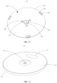
- FIG. 14 is a schematic structural view of a current collector provided in an embodiment of the disclosure.
- FIG. 15 is a schematic structural view of the current collector in FIG. 14 , viewed from another direction.
- FIG. 16 is a schematic structural view of an end cap provided in an embodiment of the disclosure.
- FIG. 17 is a schematic structural view of the end cap in FIG. 16 , viewed from another direction.
- FIG. 18 is cross-sectional view 2 of the embodiment of FIG. 1 , taken along line A-A.
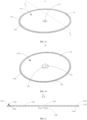
- FIG. 19 is a schematic structural view of a current collector in another embodiment of the disclosure.
- FIG. 20 is a schematic structural view of the current collector in FIG. 19 , viewed from another direction.
- FIG. 21 is a cross-sectional view of the embodiment of FIG. 19 , taken along line B-B.
- a first positioning portion 134 protrudes from the first surface 131a of the main body 131, and an outer peripheral side surface of the first positioning portion 134 is spaced apart from the outer peripheral side surface of the main body 131.
- the end cap 11 includes a first portion 113 and a second portion 114, where the second portion 114 is connected to a periphery of the first portion 113 in a bending manner. A surface of the second portion 114 close to the main body 131 is connected to the first surface 131a, and an inner peripheral side surface of the second portion 114 abuts against the outer peripheral side surface of the first positioning portion 134.
- the end cap 11 provided in the embodiment includes the first portion 113 and the second portion 114, and the second portion 114 is connected to the first portion 113 in a bending manner.
- the first portion 113 is farther away from the current collector 13 than the second portion 114.
- the first portion 113 is angled relative to the second portion 114.
- a side surface of the second portion 114 away from the first portion 113 is connected to the first surface 131a, and the first surface 131a and a surface of the first portion 113 facing the current collector 13 define a gap therebetween. It may be understood that the end cap 11 is similarly shaped to a bottle cap.
- the main body 131 provided in the embodiment includes the first positioning portion 134.
- the first positioning portion 134 plays a positioning role during assembly of the end cap 11 to the current collector 13.
- the outer peripheral side surface of the first positioning portion 134 and the outer peripheral side surface of the main body 131 define a gap therebetween, so that it is conducive to connecting the second portion 114 of the end cap 11 to the first surface 131a.
- the inner peripheral side surface of the second portion 114 abuts against the outer peripheral side surface of the first positioning portion 134. For example, part of the inner peripheral side surface of the second portion 114 abuts against the outer peripheral side surface of the first positioning portion 134.
- the end cap 11 includes the second portion 114 that extends from the first portion 113 in a direction towards the current collector 13, and the second portion 114 covers the first positioning portion 134.
- a surface of the first positioning portion 134 facing away from the main body 131 is spaced apart from a surface of the first portion 113 facing the main body 131.
- the surface of the first positioning portion 134 facing away from the main body 131 abuts against the surface of the first portion 113 facing the main body 131.
- the first positioning portion 134 is obtained by stamping the main body 131.
- the first positioning portion 134 can be formed on the first surface 131a by stamping the second surface 131b of the main body 131 in a direction from the second surface 131b to the first surface 131a.
- the first positioning portion 134 is arranged on the first surface 131a of the main body 131, and the outer peripheral side surface of the first positioning portion 134 abuts against an outer peripheral side surface of the second portion 114 of the end cap 11, to facilitate positioning during assembly of the end cap 11 to the current collector 13, so that not only the difficulty of assembly is reduced and a precision of assembly of the end cap 11 and the current collector 13 is improved, but also tooling requirements for performing welding once are reduced.
- an outer side wall of the first positioning portion 134 abuts against an inner side wall of the second portion 114 of the end cap 11, so that an area of a current-flow through region between the end cap 11 and the current collector 13 may be increased, thereby further enhancing the current-flow through capability between the end cap 11 and the current collector 13.
- the first portion 113 of the end cap 11 defines the second liquid-injection hole 112, where the second liquid-injection hole 112 is defined on the center of the first portion 113.
- the main body 131 of the current collector 13 defines the first liquid-injection hole 133, where the first liquid-injection hole 133 is defined on the center of the main body 131.
- the first positioning portion 134 is arranged on the first surface 131a of the main body 131 to play a positioning role, so that during assembly of the end cap 11 to the current collector 13, the center of the first portion 113 of the end cap 11 may be arranged corresponding to the center of the main body 131 of the current collector 13, in other words, the central axis of the end cap 11 coincides with the central axis of the current collector 13, or say, the circle center of the end cap 11 coincides with the circle center of the current collector 13.
- the first liquid-injection hole 133 is arranged corresponding to the second liquid-injection hole 112, so that efficiency of injection of liquid may be improved, the difficulty of assembly may be reduced, and the precision of assembly of the end cap 11 to the current collector 13 may be improved.
- the explosion-proof valve 111 is arranged on the first portion 113 of the end cap 11, and the explosion-proof valve 111 is used to exhaust gas generated inside the energy storage device 1.
- the first positioning portion 134 and the first portion 113 cooperatively define a gas accumulating space, where the gas accumulating space is used to accommodate the gas generated inside the energy storage device 1.
- the first positioning portion 134 is arranged on the first surface 131a of the main body 131 to define the gas accumulating space beneath the explosion-proof valve 111 on the end cap 11.
- the first positioning portion 134 can abut against the end cap 11, for example, the outer side wall of the first positioning portion 134 abuts against the inner side wall of the second portion 114, and a top surface of the first positioning portion 134 facing away from the main body 131 abuts against the surface of the first portion 113 facing the current collector 13, thereby reducing the degree of deformation and improving the structural strength of the energy storage device 1.
- FIG. 22 is a partially enlarged view of FIG. 18 . As illustrated in FIG. 18 to FIG. 22 , in an embodiment, an end of the first positioning portion 134 facing away from the main body 131 is spaced apart from the surface of the first portion 113 facing the main body 131.
- the end of the first positioning portion 134 facing away from the main body 131 and the surface of the first portion 113 facing the main body 131 defines a gap therebetween.
- the first positioning portion 134 is spaced apart from the first portion 113.
- the first positioning portion 134 is spaced apart from the first portion 113, so that the first positioning portion 134 may not directly abut against the first portion 113 of the end cap 11 during assembly of the end cap 11 and the current collector 13. In this way, the possibility of damaging the end cap 11 by the first positioning portion 134 may be reduced.
- the first portion 113 of the deformed end cap 11 may abut against the surface of the first positioning portion 134 facing away from the main body 131, thereby reducing the degree of deformation and improving the structural strength of the energy storage device 1.
- a distance H between the surface of the first positioning portion 134 facing away from the main body 131 and the surface of the first portion 113 facing the main body 131 satisfies: 0 ⁇ H ⁇ 0.5mm.
- the distance H may be equal to but is not limited to 0.05mm, 0.1mm, 0.15mm, 0.2mm, 0.25mm, 0.3mm, 0.35mm, 0.4mm, 0.45mm, 0.5mm, etc.
- the first positioning portion 134 may support the end cap 11 in the case where the end cap 11 is impacted, so as to reduce the degree of deformation of the end cap 11.
- the distance H is too small, it may be easy for the first positioning portion 134 to directly abut against the end cap 11, resulting in that the end cap 11 may be easily damaged by the first positioning portion 134.
- the first positioning portion 134 may not be able to support the end cap 11 in the case where the end cap 11 is impacted, resulting in a relatively high degree of deformation of the end cap 11, thereby reducing the structural strength of the energy storage device 1.
- the first positioning portion 134 has a first top surface 1341 and a first side surface 1342, where the first top surface 1341 faces away from the first surface 131a, and the first side surface 1342 is connected to the first top surface 1341 in a bending manner.
- the first side surface 1342 is further connected to the first surface 131a, and a connection between the first top surface 1341 and the first side surface 1342 has an arc chamfer.
- connection between the first top surface 1341 and the first side surface 1342 has an arc chamfer, which may be understood as that the connection between the first top surface 1341 and the first side surface 1342 is a curved surface and the curved surface protrudes in a direction away from the first surface 131a, in other words, the curved surface protrudes in a direction towards the first portion 113 of the end cap 11.
- a connection between the first top surface 1341 and the first side surface 1342 of each of the multiple positioning protrusions 1343 has an arc chamfer.
- a connection between the first top surface 1341 and the first side surface 1342 of each of some of the multiple positioning protrusions 1343 has an arc chamfer.
- the first positioning portion 134 includes a positioning convex ring 1344 arranged in a circumferential direction of the second portion 114
- a connection between the first top surface 1341 and the first side surface 1342 of the positioning convex ring 1344 has an arc chamfer.
- the positioning convex ring 1344 protrudes in a direction towards the first portion 113, in other words, a top of the positioning convex ring 1344 is an arc-shaped curved edge.
- connection between the first top surface 1341 and the first side surface 1342 has an arc chamfer, so that during assembly of the end cap 11 and the current collector 13, the possibility that the first positioning portion 134 scratches the end cap 11 may be reduced, or even the first positioning portion 134 is prevented from scratching the end cap 11, and thus the end cap 11 may be prevented from being scratched and accordingly metal debris may be avoided. Therefore, a short circuit inside the energy storage device 1 may be avoided, thereby improving the safety of the energy storage device 1.
- connection between the first top surface 1341 and the first side surface 1342 has an arc chamfer, so that it is conducive for assembly positioning during assembly of the end cap 11 to the current collector 13, thereby reducing the difficulty of assembly and reducing tooling requirements for performing welding once.
- the first positioning portion 134 has two structural forms. As illustrated in FIG. 19 to FIG. 20 , in an embodiment, the first positioning portion 134 includes the positioning convex ring 1344 arranged in the circumferential direction of the second portion 114.
- the first positioning portion 134 includes the positioning convex ring 1344 arranged in the circumferential direction of the second portion 114, which may be understood as that the positioning convex ring 1344 has a circular structure.
- the positioning convex ring 1344 is obtained by stamping the main body 131. By stamping the second surface 131b of the main body 131 in the direction from the second surface 131b to the first surface 131a, the positioning convex ring 1344 can be formed on the first surface 131a.
- the positioning convex ring 1344 may also be understood as a convex ring formed by folding.
- the structural strength of the current collector 13 may be increased, and thus the possibility of distortion and deformation of the current collector 13 may be reduced.
- an outer side wall of the positioning convex ring 1344 can abut against a relatively large portion of the inner side wall of the second portion 114 of the end cap 11, which may further increase the area of the current-flow through region between the end cap 11 and the current collector 13, thereby further enhancing the current-flow through capability between the end cap 11 and the current collector 13.
- the possibility that a soldering fluid flows to the gap between the end cap 11 and the current collector 13 may be reduced, or the case that the soldering fluid flows to the gap between the end cap 11 and the current collector 13 may even be avoided, thereby reducing the possibility of short circuit inside the energy storage device 1.
- the first positioning portion 134 includes multiple positioning protrusions 1343 spaced apart from each other.
- the first positioning portion 134 includes multiple positioning protrusions 1343 spaced apart from each other.
- a distance between any two adjacent positioning protrusions 1343 is equal.
- the multiple positioning protrusions 1343 are arranged on the first surface 131a at equal intervals in a circumferential direction of the second portion 114.
- each positioning protrusion 1343 is obtained by stamping the main body 131. By stamping the second surface 131b of the main body 131 in the direction from the second surface 131b to the first surface 131a, the positioning protrusion 1343 can be formed on the first surface 131a.
- the positioning protrusion 1343 may be arranged at a position according to the requirements for a product, so that for assembly of the current collector 13 and the end cap 11, the range of application of the current collector 13 may be improved.
- the positioning protrusion 1343 is inclined towards a central axis of the main body 131, and an included angle ⁇ between the first surface 131a and an outer peripheral side surface of the positioning protrusion 1343 facing away from the central axis of the main body 131 satisfies: 80° ⁇ 85°.
- the positioning protrusion 1343 is inclined towards a central axis of the main body 131, so that part of the outer peripheral side surface of the first positioning portion 134 abuts against part of the outer peripheral side surface of the second portion 114. Therefore, it is conducive for positioning during assembly of the end cap 11 to the current collector 13, and thus not only the difficulty of assembly may be reduced and the precision of assembly of the end cap 11 to the current collector 13 may be increased, but also tooling requirements for performing welding once may be reduced.
- the positioning protrusion 1343 is obtained by stamping the main body 131.
- the inclined positioning protrusion 1343 can be formed.
- the positioning protrusion 1343 provided in the embodiment is a folding protrusion that is folded about 90 degrees relative to a direction towards the first portion 113, and the folding protrusion at an outer side of the first surface 131a (i.e., at a position of the first surface 131a away from the center of the first surface 131a) may be inclined at an angle of 5 to 10 degrees relative to the center of the first surface 131a.
- the included angle ⁇ between the first surface 131a and an outer peripheral side surface of the positioning protrusion 1343 facing away from the central axis of the main body 131 satisfies: 80° ⁇ 85°.
- the included angle ⁇ may be equal to but is not limited to 80°, 81°, 82°, 83°, 84°, 85°, and the like.
- the included angle ⁇ satisfies 80° ⁇ 85°, not only it is conducive for positioning during assembly of the end cap 11to the current collector 13, but also the possibility of scratching the end cap 11 by the first positioning portion 134 may be reduced.
- the included angle ⁇ is relatively small, it is not conducive for positioning during assembly of the end cap 11 to the current collector 13.
- the included angle ⁇ is too large, it may be easy for the first positioning portion 134 to directly abut against the end cap 11, and thus the end cap 11 may be damaged by the first positioning portion 134 easily.
- the main body 131 defines multiple first through holes 135 penetrating through both the first surface 131a and the second surface 131b.
- the main body 131 defines multiple first through holes 135 penetrating through both the first surface 131a and the second surface 131b.
- a distance between any two adjacent first through holes 135 is equal.
- the multiple first through holes 135 are arranged on the main body 131 at equal intervals.
- At least one first through hole 135 and at least one positioning protrusion 1343 that is connected to an inner side wall of the first through hole 135 cooperatively form a first folding group, and the first folding group and the main body 131 are integrally formed by a stamping process.
- the positioning protrusion 1343 and the first through hole 135 can both be formed on the main body 131 by stamping the second surface 131b of the main body 131 in the direction from the second surface 131b to the first surface 131a.
- two structures i.e., one first through hole 135 and one positioning protrusion 1343, may be obtained by performing stamping once. In this way, the process of manufacturing the energy storage device 1 may be simplified, and the efficiency of manufacturing the energy storage device 1 may be improved.
- multiple limiting protrusions 136 are arranged spaced apart from each other on the first surface 131a of the main body 131.
- An outer peripheral side surface of the limiting protrusion 136 is spaced apart from the outer peripheral side surface of the main body 131.
- the end cap 11 includes the first portion 113 and the second portion 114, where the second portion 114 is connected to the periphery of the first portion 113 in a bending manner.
- a surface of the second portion 114 close to the main body 131 is connected to the first surface 131a, and a surface of the limiting protrusion 136 facing away from the main body 131 abuts against the surface of the first portion 113 facing the main body 131.
- the end cap 11 provided in the embodiment includes the first portion 113 and the second portion 114, and the second portion 114 is connected to the first portion 113 in a bending manner.
- the first portion 113 is farther away from the current collector 13 than the second portion 114.
- the first portion 113 is angled relative to the second portion 114.
- a side surface of the second portion 114 away from the first portion 113 is connected to the first surface 131a.
- the first surface 131a and the surface of the first portion 113 facing the current collector 13 define a gap therebetween. It may be understood that, the end cap 11 is similarly shaped to a bottle cap.
- the main body 131 provided in the embodiment includes the limiting protrusion 136.
- the limiting protrusion 136 is used to limit and support the end cap 11, to play a limiting and supporting role.
- the surface of the limiting protrusion 136 facing away from the main body 131 abuts against the surface of the first portion 113 facing the main body 131.
- the limiting protrusion 136 abuts against the first portion 113 to support the end cap 11.
- the end cap 11 includes the second portion 114 that extends from the first portion 113 in a direction towards the current collector 13, and the second portion 114 covers the first positioning portion 134.
- a distance from a surface of the limiting protrusion 136 facing the main body 131 to the surface of the limiting protrusion 136 facing away from the main body 131 is equal to a distance from the first surface 131a of the main body 131 to the surface of the first portion 113 facing the main body 131.
- the height of the limiting protrusion 136 is equal to the distance from the first surface 131a of the main body 131 to the surface of the first portion 113 facing the main body 131.
- the multiple limiting protrusions 136 are arranged on the first surface 131a at equal intervals.
- the limiting protrusion 136 is obtained by stamping the main body 131. By stamping the second surface 131b of the main body 131 in the direction from the second surface 131b to the first surface 131a, the limiting protrusion 136 can be formed on the first surface 131a.
- the multiple limiting protrusions 136 are arranged close to the central axis of the current collector 13. The multiple limiting protrusions 136 are able to support a central portion of the current collector 13, thereby preventing the current collector 13 and the end cap 11 from deformation, and thus improving the structural strength of the energy storage device 1.
- the multiple limiting protrusions 136 and the multiple first positioning portions 134 are spaced apart on the first surface 131a of the main body 131, the multiple limiting protrusions 136 are closer to the central axis of the main body 131 than the multiple first positioning portions 134.
- each limiting protrusion 136 is a protrusion arranged on the inner side of the first surface 131a, i.e., each limiting protrusion 136 is arranged adjacent to the center of the first surface 131a, and each first positioning portion 134 is a structural member arranged on the outer side of the first surface 131a, i.e., each first positioning portion 134 is arranged at a position of the first surface 131a away from the center of the first surface 131a.
- the limiting protrusion 136 is arranged on the first surface 131a of the main body 131, and the limiting protrusion 136 abuts against the first portion 113 of the end cap 11 to support the end cap 11, and thus the structural strength of the end cap 11 and the current collector 13 may be improved.
- the limiting protrusion 136 is able to abut against the end cap 11 to prevent the current collector 13 and the end cap 11 from bulging upwards or denting downwards for example, thereby reducing the degree of deformation and further improving the structural strength of the energy storage device 1.
- the explosion-proof valve 111 is arranged on the first portion 113 of the end cap 11, and the explosion-proof valve 111 is used to exhaust gas generated inside the energy storage device 1.
- the limiting protrusion 136 and the first portion 113 cooperatively define a gas accumulating space, where the gas accumulating space is used to accommodate the gas generated inside the energy storage device 1.
- the limiting protrusion 136 is arranged on the first surface 131a of the main body 131 to define the gas accumulating space beneath the explosion-proof valve 111 on the end cap 11.
- the limiting protrusion 136 has a second top surface 1361 and a second side surface 1362.
- the second top surface 1361 faces away from the first surface 131a, and the second side surface 1362 is connected to the second top surface 1361 in a bending manner.
- the second side surface 1362 is further connected to the first surface 131a, and a connection between the second top surface 1361 and the second side surface 1362 has an arc chamfer.
- connection between the second top surface 1361 and the second side surface 1362 has an arc chamfer, which may be understood as that the connection between the second top surface 1361 and the second side surface 1362 is a curved surface and the curved surface protrudes in a direction away from the first surface 131a, in other words, the curved surface protrudes in a direction towards the first portion 113 of the end cap 11.
- connection between the second top surface 1361 and the second side surface 1362 of each limiting protrusion 136 has an arc chamfer, or the connection between the second top surface 1361 and the second side surface 1362 of some of the limiting protrusions 136 has an arc chamfer.
- connection between the second top surface 1361 and the second side surface 1362 has an arc chamfer, so that during assembly of the end cap 11 and the current collector 13, the possibility that the limiting protrusion 136 scratches the end cap 11 may be reduced, or even the limiting protrusion 136 is prevented from scratching the end cap 11, and thus the end cap 11 may be prevented from being scratched and accordingly metal debris may be avoided. Therefore, the performance of the energy storage device 1 may not be affected, thereby improving the safety of the energy storage device 1.
- a peripheral side surface of the limiting protrusion 136 is perpendicular to the first surface 131a.
- the peripheral side surface of the limiting protrusion 136 is perpendicular to the first surface 131a, in other words, the limiting protrusion 136 is perpendicular to the main body 131, so that it is conducive for the limiting protrusion 136 to abut against the first portion 113 of the end cap 11 to support the end cap 11, thereby improving the structural strength of the end cap 11 and the current collector 13.
- the limiting protrusion 136 is obtained by stamping the main body 131.
- the limiting protrusion 136 that is perpendicular to the first surface 131a can be formed. It may be understood that the limiting protrusion 136 provided in the embodiment is a folding protrusion that is folded about 90 degrees relative to a direction towards the first portion 113.
- the main body 131 defines multiple second through holes 137 penetrating through both the first surface 131a and the second surface 131b.
- the second through hole 137 is configured to allow the electrolyte to flow to the housing 12.
- the main body 131 defines multiple second through holes 137 penetrating through both the first surface 131a and the second surface 131b.
- a distance between any two adjacent second through holes 137 is equal.
- the multiple second through holes 137 are arranged on the main body 131 at equal intervals.
- At least one second through hole 137 and at least one limiting protrusion 136 that is connected with an inner side wall of the second through hole 137 cooperatively form a second folding group, and the second folding group and the main body 131 are integrally formed by a stamping process.
- the limiting protrusion 136 and the second through hole 137 can both be formed on the main body 131 by stamping the second surface 131b of the main body 131 in the direction from the second surface 131b to the first surface 131a.
- two structures i.e., one second through hole 137 and one limiting protrusion 136, may be obtained by performing stamping once. In this way, the process of manufacturing the energy storage device 1 may be simplified, and the efficiency of manufacturing the energy storage device 1 may be improved.
- the energy storage device 1 further includes the electrode assembly 14.
- the housing 12 defines the accommodating cavity 121.
- the electrode assembly 14 is arranged in the accommodating cavity 121.
- the electrode assembly 14 has a winding shape and has a hollow structure 141, a second positioning portion 138 is arranged on the second surface 131b of the main body 131, and at least part of the second positioning portion 138 is inserted into the hollow structure 141.
- the energy storage device 1 provided in the embodiment further includes the electrode assembly 14, and the electrode assembly 14 is arranged in the accommodating cavity 121.
- the energy storage device 1 further includes an electrolyte (not illustrated) in the accommodating cavity 121, and at least part of the electrode assembly 14 is immersed by the electrolyte.
- the electrode assembly 14 is connected to the second surface 131b of the current collector 13.
- the electrode assembly 14 is welded to the current collector 13.
- the electrode assembly 14 has a winding shape and has the hollow structure 141.
- the hollow structure 141 is an electrically insulated structural pipe formed by winding of plural layers of separators.
- the hollow structure 141 is positioned at the center of the electrode assembly 14.
- the main body 131 provided in the embodiment includes the second positioning portion 138, where during assembly of the current collector 13 to the electrode assembly 14, the second positioning portion 138 plays a positioning role. At least part of the second positioning portion 138 is inserted into the hollow structure 141. For example, part of the second positioning portion 138 is inserted into the hollow structure 141. For example, the second positioning portion 138 is completely inserted into the hollow structure 141. For example, the second positioning portion 138 abuts against part of an inner side wall of the hollow structure 141. For example, the second positioning portion 138 is spaced apart from the hollow structure 141.
- the second positioning portion 138 is a protrusion, and at least part of the protrusion is inserted into the hollow structure 141.
- the second positioning portion 138 is arranged on the second surface 131b of the main body 131, and at least part of the second positioning portion 138 is inserted into the hollow structure 141, to facilitate positioning during assembly of the electrode assembly 14 and the current collector 13, so that not only the difficulty of assembly is reduced and the precision of assembly of the electrode assembly 14 and the current collector 13 is improved, but also tooling requirements for performing welding once are reduced.
- the second positioning portion 138 is positioned on the center of the current collector 13, and the hollow structure 141 is positioned on the center of the electrode assembly 14.
- the second positioning portion 138 is arranged on the second surface 131b of the main body 131 to play a positioning role, so that during assembly of the current collector 13 and the electrode assembly 14, the center of the current collector 13 may be arranged corresponding to the center of the electrode assembly 14, in other words, the central axis of the current collector 13 coincides with the central axis of the electrode assembly 14, or say, the circle center of the current collector 13 coincides with the circle center of the electrode assembly 14, thereby improving assembly stability of the energy storage device 1.
- the main body 131 defines the first liquid-injection hole 133 penetrating through both the first surface 131a and a surface of the second positioning portion 138 facing the electrode assembly 14.
- An orthographic projection of the first liquid-injection hole 133 on a surface of the electrode assembly 14 facing the current collector 13 falls within the hollow structure 141.
- the end cap 11 defines the second liquid-injection hole 112.
- the end cap 11 and the current collector 13 cooperatively define a cavity 115, and the first liquid-injection hole 133 and the second liquid-injection hole 112 are both in communication with the cavity 115.
- the main body 131 defines the first liquid-injection hole 133 penetrating through both the first surface 131a and the surface of the second positioning portion 138 facing the electrode assembly 14.
- the first liquid-injection hole 133 penetrates through both the first surface 131a and the surface of the second positioning portion 138 facing away from the end cap 11.
- the orthographic projection of the first liquid-injection hole 133 on the surface of the electrode assembly 14 facing the current collector 13 falls within the hollow structure 141.
- the first liquid-injection hole 133 is arranged corresponding to the hollow structure 141.
- the first liquid-injection hole 133 is arranged close to or directly aligned with the center of the electrode assembly 14.
- the second positioning portion 138 is a convex ring, and at least part of the convex ring is inserted into the hollow structure 141.
- the end cap 11 defines the second liquid-injection hole 112.
- the end cap 11 and the current collector 13 cooperatively define the cavity 115, and the first liquid-injection hole 133 and the second liquid-injection hole 112 both communicate with the cavity 115.
- the electrolyte may flow to the cavity 115 through the second liquid-injection hole 112, and then flow to the second liquid-injection hole 112 from the cavity 115.
- the first liquid-injection hole 133 and the second liquid-injection hole 112 are arranged correspondingly.
- the temperature of the hollow structure 141 of the electrode assembly 14 is relatively high, so that the migration speed of active ions in the electrolyte in the hollow structure 141 of the electrode assembly 14 may be increased, and side reactions may be increased, resulting in quick consumption of the electrolyte in the hollow structure 141 of the electrode assembly 14.
- the electrolyte can flow through the first liquid-injection hole 133 to the electrode assembly 14 to immerse the electrode assembly 14, in other words, the electrolyte may directly immerse the hollow structure 141 of the electrode assembly 14, so that it can be ensured that there may be sufficient electrolyte in the hollow structure 141 of the electrode assembly 14, thereby prolonging the cycle life of the cell.
- the electrolyte may diffuse outward from the hollow structure 141 of the electrode assembly 14, so that the electrolyte is evenly injected in various directions of the electrode assembly 14, and thus the uniformity of the electrolyte inside the electrode assembly 14 may be enhanced, and it is conducive to improving the performance of the energy storage device 1.
- FIG. 23 is a schematic structural view of an electricity-consumption device provided in an embodiment of the disclosure. As illustrated in FIG. 23 , an electricity-consumption device 2 is further provided in the disclosure.
- the electricity-consumption device 2 includes a device body 21 and the energy storage device 1 mentioned above, and the energy storage device 1 is configured to power the device body 21.
- the electricity-consumption device 2 provided in the embodiment of the disclosure may be but is not limited to a portable electrical device such as a cellphone, a tablet computer, a laptop computer, a desktop computer, a smart toy, a smart bracelet, a smart watch, an electronic reader, a game console, a toy, etc..
- the electricity-consumption device 2 provided in the embodiment of the disclosure may be large equipment such as an e-bike, an electric vehicle, a ship, a spacecraft, etc.
- the electricity-consumption device 2 in this embodiment is only a form of the electricity-consumption device 2 to which the cell is applied, and should not be understood as a limitation to the electricity-consumption device 2 provided in the disclosure, nor should it be understood as a limitation to the cell provided in each of the embodiments of the disclosure.
- the energy storage device 1 provided in the disclosure is used.
- the current collector 13 is arranged between the end cap 11 and the housing 12 and is welded to both the peripheral side surface of the end cap 11 and the peripheral side surface of the housing 12, and thus the welding region between the end cap 11 and the current collector 13 may be enlarged, thereby improving the current-flow through capability between the end cap 11 and the current collector 13, and accordingly improving the strength of connection among the end cap 11, the current collector 13, and the housing 12. Therefore, the energy storage device 1 may provide stable electricity for the device body 21 when powering the device body 21.
- FIG. 24 is a process flow chart of a welding method for an energy storage device provided in an embodiment of the disclosure.
- the disclosure further provides a welding method for the energy storage device 1, where the welding method includes operations at S100, S200, and S300. Detailed illustration of the operations at S100, S200, and S300 are illustrated as follows.
- the welding method includes the following.
- an electrode assembly 14 is further provided. Further, optionally, the electrode assembly 14 has a winding shape. Optionally, the electrode assembly 14 has a winding shape and has a hollow structure 141, and the current collector 13 includes a second positioning portion 138.
- the wound electrode assembly 14 is placed inside the housing 12, and a tab of the electrode assembly 14 is exposed through an opening of the housing 12.
- the current collector 13 is mounted to the electrode assembly 14. Specifically, the current collector 13 is positioned on the tab of the wound electrode assembly 14. Then, a welding process is performed on the current collector 13 and the tab. Specifically, the positive current collector 13 is welded to the tab by laser penetration welding.
- a melt width of welding ranges from 1mm to 2mm
- a melt depth of welding ranges from 2mm to 4mm.
- At least part of the second positioning portion 138 is inserted into the hollow structure 141.
- a first positioning portion 134 is arranged on the current collector 13, where the first positioning portion 134 is arranged at one of two opposite sides of the current collector 13, and the second positioning portion 138 is arranged at the other of the two opposite sides of the current collector 13.
- the end cap 11 includes a first portion 113 and a second portion 114, and the second portion 114 is connected to a periphery of the first portion 113 in a bending manner.
- an inner peripheral side surface of the second portion 114 abuts against an outer peripheral side surface of the first positioning portion 134. It may be understood that, the end cap 11 is sleeved on the top of the current collector 13, and the end cap 11 covers an outer peripheral surface of the first positioning portion 134.
- the current collector 13 subject to the welding includes a main body 131 and a welding portion 132.
- the main body 131 and the welding portion 132 are integrally formed.
- the main body 131 has a first surface 131a and a second surface 131b facing away from the first surface 131a.
- the end cap 11 is connected to the first surface 131a of the main body 131, and the housing 12 is connected to the second surface 131b of the main body 131.
- the welding portion 132 is connected to an outer peripheral side surface of the end cap 11, an outer peripheral side surface of the housing 12, and an outer peripheral side surface of the main body 131.
- the end cap 11, the current collector 13, and the housing 12 are placed horizontally and clamped by a welding fixture, and a laser welding head is adjusted to be aligned with the outer peripheral side surface of the current collector 13. Then, the laser welding head is started and the fixture is rotated at a constant speed, and a side sealing welding is completed after the fixture is rotated by a full turn.
- Specific structure of the energy storage device 1 after welding is as mentioned above, which will not be repeated herein.
- the welding method for the energy storage device 1 provided in the embodiment is simple and easy to operate.
- the current collector 13 is arranged between the end cap 11 and the housing 12, and by means of performing welding once, the current collector 13 is welded to both the peripheral side surface of the end cap 11 and the peripheral side surface of the housing 12 to realize side sealing welding. In this way, the welding region between the end cap 11 and the current collector 13 may be enlarged, thereby improving the current-flow through capability between the end cap 11 and the current collector 13, and accordingly improving the strength of connection among the end cap 11, the current collector 13, and the housing 12.
- FIG. 25 is a process flow chart of a welding method for an energy storage device provided in another embodiment of the disclosure.
- the operation of exposing the outer peripheral side surface of the current collector 13 at S200 may include the following.
- the end cap 11, the current collector 13, and the housing 12 are placed horizontally and clamped by the welding fixture, and the laser welding head is adjusted to be aligned with a welding convex ring of the current collector 13 that protrudes from both a side wall surface of the end cap 11 and a side wall surface of the housing 12.
- a welding portion 132 of the energy storage device 1 obtained through the welding method of the disclosure may be understood as a melted welding convex ring after welding.
- the current collector 13 Before welding the current collector 13, the end cap 11, and the housing 12 together, the current collector 13 may be arranged protruding from the end cap 11 and the housing 12. It may be understood that, the current collector 13 has a welding convex ring protruding from both the outer side wall of the end cap 11 and the outer side wall of the housing 12, where the welding convex ring is used for welding. In this way, it is conducive to aligning the laser welding head with the welding convex ring to directly heat the welding convex ring, then the housing 12 is rotated at a constant speed to complete a welding. In this case, the welding convex ring is firstly heated and melted to achieve "top melting".
- the welding convex ring melted flows to two sides under the action of gravity, to fill the gap between the end cap 11 and the current collector 13 or the gap between the housing 12 and the current collector 13, then the welding convex ring melted is fused together with the end cap 11 and the housing 12 that are melted subsequently, thereby further enhancing the structural strength and airtightness of the welding region. It may also be understood that, the welding convex ring may be melted to a solder. In addition, due to the effect of "top melting" of the welding convex ring, requirements for the machining precision of a joint surface of the end cap 11 and a joint surface of the housing 12 are reduced, and thus the manufacturing cost of components of the energy storage device 1 is further reduced.
- the current collector 13 in an embodiment, in the operation of exposing the outer peripheral side surface of the current collector 13 at S200, that is, in the operation of making the current collector 13 protrude from both the end cap 11 and the housing 12 at S210, the current collector 13 protrudes from both the end cap 11 and the housing 12 by a width L3, and the width L3 satisfies: 0.25mm ⁇ L3 ⁇ 2mm.
- the current collector 13 protrudes from the end cap 11 and the housing 12 by the width L3, and the width L3 satisfies: 0.25mm ⁇ L3 ⁇ 2mm. It may be understood that, the welding convex ring protrudes from the end cap 11 and the housing 12 by the width L3, and the width L3 satisfies: 0.25mm ⁇ L3 ⁇ 2mm.
- the width L3 refers to a distance from an outer peripheral side wall of the current collector 13 to an outer peripheral side wall of the end cap 11, or a distance from the outer peripheral side wall of the current collector 13 to an outer peripheral side wall of the housing 12.
- the width L3 may be equal to but is not limited to 0.25mm, 0.3mm, 0.35mm, 0.4mm, 0.45mm, 0.5mm, 0.55mm, 0.6mm, 0.65mm, 0.7mm, 0.75mm, 0.8mm, 0.85mm, 0.9mm, 0.95mm, 1mm, 1.1mm, 1.2mm, 1.3mm, 1.4mm, 1.5mm, 1.6mm, 1.7mm, 1.8mm, 1.9mm, 2mm, etc.
- the width L3 satisfies 0.25mm ⁇ L3 ⁇ 2mm, not only requirements for the machining precision of the joint surface of the end cap 11 and the joint surface of the housing 12 may be reduced and the structural strength and airtightness of the welding region may be enhanced, but also the time for welding may be reduced, the efficiency of welding may be improved, and the manufacturing cost may be reduced.
- the width L3 is too small, it is not conducive to aligning the laser welding head with the welding convex ring, and thus requirements for the machining precision of the joint surface of the end cap 11 and the joint surface of the housing 12 may be increased.
Landscapes
- Chemical & Material Sciences (AREA)
- Chemical Kinetics & Catalysis (AREA)
- Electrochemistry (AREA)
- General Chemical & Material Sciences (AREA)
- Engineering & Computer Science (AREA)
- Physics & Mathematics (AREA)
- Optics & Photonics (AREA)
- Manufacturing & Machinery (AREA)
- Plasma & Fusion (AREA)
- Mechanical Engineering (AREA)
- Sealing Battery Cases Or Jackets (AREA)
- Connection Of Batteries Or Terminals (AREA)
Abstract
Description
- The disclosure relates to the field of energy storage technologies, and in particular to an energy storage device, a welding method for an energy storage device, and an electricity-consumption device.
- A secondary cell, also known as a rechargeable cell or a storage cell, refers to a cell that can be charged after discharge to activate active substance of the cell for reuse. Since the secondary cell is reusable, the secondary cell gradually becomes a main power source for electricity-consumption devices. As the demand for the secondary cell gradually increases, people have increasingly higher requirements for various performances of the secondary cell, especially for the energy density per unit volume of the cell. However, for a cylindrical secondary cell, a gap defined between a wound electrode assembly and an end cap at one side of the cell and a gap defined between the wound electrode assembly and an end cap at the other side of the cell are key factors for restricting the energy density per unit volume of the cell.
- In view of above, the disclosure provides an energy storage device, a welding method for an energy storage device, and an electricity-consumption device. A current collector of the energy storage device is welded to a peripheral side surface of an end cap and a peripheral side surface of a housing, thereby improving a strength of connection among the end cap, the current collector, and the housing.
- In a first aspect of the disclosure, an energy storage device is provided. The energy storage device includes an end cap, a housing, and a current collector arranged between the end cap and the housing. An outer peripheral side surface of the end cap is flush with an outer peripheral side surface of the housing. The current collector includes a main body and a welding portion. The main body and the welding portion are integrally formed. The main body has a first surface and a second surface facing away from the first surface. The end cap is connected to the first surface of the main body, the housing is connected to the second surface of the main body, and the welding portion is connected to the outer peripheral side surface of the end cap, the outer peripheral side surface of the housing, and an outer peripheral side surface of the main body. The current collector satisfies one of the following: the outer peripheral side surface of the main body is flush with both the outer peripheral side surface of the end cap and the outer peripheral side surface of the housing, in a radial direction of the current collector; and the outer peripheral side surface of the main body protrudes from both the outer peripheral side surface of the end cap and the outer peripheral side surface of the housing, in the radial direction of the current collector. The welding portion protrudes from the end cap by a width L1, where the width L1 satisfies: 0.05mm≤L1≤1.45mm; and the welding portion protrudes from the housing by a width L2, where the width L2 satisfies: 0.05mm≤L2≤1.45mm.
- In a second aspect of the disclosure, an electricity-consumption device is provided. The electricity-consumption device includes a device body and the energy storage device provided in the first aspect of the disclosure, where the energy storage device is configured to power the device body.
- In a third aspect of the disclosure, a welding method for an energy storage device is provided. The welding method includes the following. Provide an end cap, a housing, and a current collector. Make the end cap abut against a surface of the current collector and make the housing abut against a surface of the current collector facing away from the end cap, and expose an outer peripheral side surface of the current collector. Perform circumferential laser welding on an outer peripheral side of the current collector to fixedly connect the current collector to both the end cap and the housing, where the current collector subject to the welding includes a main body and a welding portion. The main body and the welding portion are integrally formed. The main body has a first surface and a second surface facing away from the first surface, the end cap is connected to the first surface of the main body, and the housing is connected to the second surface of the main body. The welding portion is connected to an outer peripheral side surface of the end cap, an outer peripheral side surface of the housing, and an outer peripheral side surface of the main body.
- In order to describe technical solutions in embodiments of the disclosure more clearly, the following will give an introduction to the accompanying drawings required for describing embodiments of the disclosure.
-
FIG. 1 is a schematic structural view of an energy storage device provided in an embodiment of the disclosure. -
FIG. 2 is a structural exploded view of an energy storage device provided in an embodiment of the disclosure. -
FIG. 3 iscross-sectional view 1 of the embodiment ofFIG. 1 , taken along line A-A. -
FIG. 4 is partially enlargedview 1 ofFIG. 3 . -
FIG. 5 is partially enlargedview 2 ofFIG. 3 . -
FIG. 6 is partially enlarged view 3 ofFIG. 3 . -
FIG. 7 is partially enlarged view 4 ofFIG. 3 . -
FIG. 8 is partially enlarged view 5 ofFIG. 3 . -
FIG. 9 is partially enlarged view 6 ofFIG. 3 . -
FIG. 10 is partially enlarged view 7 ofFIG. 3 . -
FIG. 11 is partially enlarged view 8 ofFIG. 3 . -
FIG. 12 is partially enlarged view 9 ofFIG. 3 . -
FIG. 13 is a cross-sectional view of a current collector, an end cap, and a housing provided in the embodiment ofFIG. 1 , taken along line A-A, the current collector, the end cap, and the housing being not welded together. -
FIG. 14 is a schematic structural view of a current collector provided in an embodiment of the disclosure. -
FIG. 15 is a schematic structural view of the current collector inFIG. 14 , viewed from another direction. -
FIG. 16 is a schematic structural view of an end cap provided in an embodiment of the disclosure. -
FIG. 17 is a schematic structural view of the end cap inFIG. 16 , viewed from another direction. -
FIG. 18 iscross-sectional view 2 of the embodiment ofFIG. 1 , taken along line A-A. -
FIG. 19 is a schematic structural view of a current collector in another embodiment of the disclosure. -
FIG. 20 is a schematic structural view of the current collector inFIG. 19 , viewed from another direction. -
FIG. 21 is a cross-sectional view of the embodiment ofFIG. 19 , taken along line B-B. -
FIG. 22 is a partially enlarged view ofFIG. 18 . -
FIG. 23 is a schematic structural view of an electricity-consumption device provided in an embodiment of the disclosure. -
FIG. 24 is a process flow chart of a welding method for an energy storage device provided in an embodiment of the disclosure. -
FIG. 25 is a process flow chart of a welding method for an energy storage device provided in another embodiment of the disclosure. - Illustration of reference signs: energy storage device-1; end cap-11; explosion-proof valve-111; second liquid-injection hole-112; first portion-113; second portion-114; cavity-115; housing-12; accommodating cavity-121; current collector-13; main body-131; first surface-131a; second surface-131b; welding portion-132; first liquid-injection hole-133; first positioning portion-134; first top surface-1341; first side surface-1342; positioning protrusion-1343; positioning convex ring-1344; first through hole-135; limiting protrusion-136; second top surface-1361; second side surface-1362; second through hole-137; second positioning portion-138; electrode assembly-14; hollow structure-141; electricity-consumption device -2; device body-21.
- The following are exemplary embodiments of the disclosure. It may be noted that, for those of ordinary skill in the art, modifications and improvements may be made within the principles of the disclosure, and these modifications and improvements may be included in the scope of protection of the disclosure.
- Reference is made to
FIG. 1 to FIG. 9 .FIG. 1 is a schematic structural view of an energy storage device provided in an embodiment of the disclosure.FIG. 2 is a structural exploded view of an energy storage device provided in an embodiment of the disclosure.FIG. 3 iscross-sectional view 1 of the embodiment ofFIG. 1 , taken along line A-A.FIG. 4 is partially enlargedview 1 ofFIG. 3 .FIG. 5 is partiallyenlarged view 2 ofFIG. 3 .FIG. 6 is partially enlarged view 3 ofFIG. 3 .FIG. 7 is partially enlarged view 4 ofFIG. 3 .FIG. 8 is partially enlarged view 5 ofFIG. 3 .FIG. 9 is partially enlarged view 6 ofFIG. 3 . - An
energy storage device 1 is provided in the disclosure. Acurrent collector 13 of theenergy storage device 1 is welded to both a peripheral side surface of anend cap 11 and a peripheral side surface of ahousing 12, so that a strength of connection among theend cap 11, thecurrent collector 13, and thehousing 12 may be improved. Optionally, theenergy storage device 1 may be but is not limited to a lithium-ion secondary cell, a lithium-ion primary cell, a lithium sulfur cell, a sodium lithium-ion cell, a sodium-ion cell, a magnesium-ion cell, etc. - The
energy storage device 1 provided in the embodiment includes theend cap 11, thehousing 12, and thecurrent collector 13 arranged between theend cap 11 and thehousing 12. Thecurrent collector 13 includes amain body 131 and awelding portion 132. Themain body 131 and thewelding portion 132 are integrally formed. Themain body 131 has afirst surface 131a and asecond surface 131b facing away from thefirst surface 131a. Theend cap 11 is connected to thefirst surface 131a of themain body 131, and thehousing 12 is connected to thesecond surface 131b of themain body 131. Thewelding portion 132 is connected to an outer peripheral side surface of theend cap 11, an outer peripheral side surface of thehousing 12, and an outer peripheral side surface of themain body 131. - In addition, the terms "include" and "comprise", as well as variations thereof are intended to cover non-exclusive inclusion. The terms "first", "second" and the like in the specification, the claims, and the accompany drawings of the disclosure are used to distinguish different objects rather than describe a particular order.
- The
energy storage device 1 provided in the embodiment includes theend cap 11, where theend cap 11 is electrically connected to thecurrent collector 13, and is used to fix and protect other components. Theend cap 11 is connected to thecurrent collector 13. For example, theend cap 11 is partially welded to thecurrent collector 13. For another example, theend cap 11 partially abuts against thecurrent collector 13. Optionally, theend cap 11 may be but is not limited to circular, rectangular, cap-shaped, etc. Optionally, theend cap 11 may be apositive end cap 11 or anegative end cap 11. - Optionally, the
end cap 11 includes an explosion-proof valve 111. The explosion-proof valve 111 is used to exhaust gas generated inside theenergy storage device 1 to prevent explosion, thereby improving the safety of theenergy storage device 1. Optionally, theend cap 11 includes a second liquid-injection hole 112 for injection of electrolyte. Optionally, the second liquid-injection hole 112 is defined on the center of theend cap 11. - The
energy storage device 1 provided in the embodiment further includes thehousing 12. Thehousing 12 is used to accommodate, fix, and protect other components. Thehousing 12 is connected to thecurrent collector 13. For example, thehousing 12 is partially welded to thecurrent collector 13. For another example, thehousing 12 partially abuts against thecurrent collector 13. Optionally, a material of thehousing 12 may be a metal material such as aluminum, copper, or alloy. Optionally, thehousing 12 may be but is not limited to circular, rectangular, etc. Optionally, the shape of thehousing 12 is matched with the shape of theend cap 11, or thehousing 12 has the same shape as theend cap 11. Optionally, theenergy storage device 1 further includes anelectrode assembly 14. Thehousing 12 defines anaccommodating cavity 121, and theelectrode assembly 14 is arranged in theaccommodating cavity 121. - The
energy storage device 1 provided in the embodiment further includes thecurrent collector 13. Thecurrent collector 13 is electrically connected to theend cap 11, thehousing 12, and theelectrode assembly 14. Theend cap 11 is welded to a surface of thecurrent collector 13, and thehousing 12 is welded to another surface of thecurrent collector 13 facing away from theend cap 11. Thecurrent collector 13 includes themain body 131 and thewelding portion 132, and themain body 131 and thewelding portion 132 are integrally formed. Themain body 131 may be understood as a portion of thecurrent collector 13 that is not changed before and after welding. Thewelding portion 132 may be understood as a portion of thecurrent collector 13 welded to both theend cap 11 and thehousing 12, formed after thecurrent collector 13 is subject to welding. That is, thewelding portion 132 is a welding seam formed by cooling and solidification of a molten metal after welding. Optionally, an outer side surface of themain body 131 and an outer side surface of thewelding portion 132 may both be a flat surface or a curved surface, which is not limited in the disclosure. - It may be noted that, in order to more clearly indicate the
main body 131 and thewelding portion 132, themain body 131 and thewelding portion 132 are marked with different patterns inFIG. 7 to FIG. 9 . However, in actual production, themain body 131 and thewelding portion 132 are integrally formed, as illustrated inFIG. 4 to FIG. 6 . As illustrated inFIG. 7 to FIG. 9 , thefirst surface 131a of themain body 131 is connected to theend cap 11. At least part of theend cap 11 abuts against thefirst surface 131a of themain body 131. For example, a surface of theend cap 11 facing thecurrent collector 13 abuts against thefirst surface 131a. For another example, since part of a solder flows to a position between themain body 131 and theend cap 11, a part of the surface of theend cap 11 facing thecurrent collector 13 abuts against thefirst surface 131a, and another part of the surface of theend cap 11 facing thecurrent collector 13 abuts against thewelding portion 132. At least part of thehousing 12 abuts against thesecond surface 131b of themain body 131. For example, a surface of thehousing 12 facing thecurrent collector 13 abuts against thesecond surface 131b. For another example, since part of a solder flows to a position between themain body 131 and thehousing 12, a part of the surface of thehousing 12 facing thecurrent collector 13 abuts against thesecond surface 131b, and another part of the surface of thehousing 12 facing thecurrent collector 13 abuts against thewelding portion 132. - The
welding portion 132 is connected to the outer peripheral side surface of themain body 131, and the outer peripheral side surface of themain body 131 is connected to both thefirst surface 131a and thesecond surface 131b. Thewelding portion 132 is further connected to both theend cap 11 and thehousing 12. For example, thewelding portion 132 is connected to an outer peripheral side of thehousing 12. For another example, thewelding portion 132 is connected to an outer peripheral side of theend cap 11. For another example, thewelding portion 132 is connected to the surface of thehousing 12 facing thecurrent collector 13. For another example, thewelding portion 132 is connected to the surface of theend cap 11 facing thecurrent collector 13. - It may be understood that, the
welding portion 132 is the portion of thecurrent collector 13 that is welded to theend cap 11 and thehousing 12, formed after thecurrent collector 13 is subject to welding, and thus thewelding portion 132 may be connected to theend cap 11 and thehousing 12 in various ways. The above mentioned connection between thewelding portion 132 and theend cap 11 and between thewelding portion 132 and thehousing 12 may exist either alone or in various combinations with each other. - It may be understood that, the
current collector 13 in the embodiment does not include a protrusion structure facing theend cap 11. The protrusion structure herein is a protrusion that is used for welding thecurrent collector 13 to theend cap 11 in the related art. Optionally, thecurrent collector 13 defines a first liquid-injection hole 133 for injection of electrolyte. Further, optionally, the first liquid-injection hole 133 is defined on the center of thecurrent collector 13. Further, optionally, the first liquid-injection hole 133 is arranged facing away from the second liquid-injection hole 112. - Optionally, the
current collector 13 may be but is not limited to circular, rectangular, and the like. Optionally, thecurrent collector 13, thehousing 12, and theend cap 11 are matched with each other in shape. In other words, thecurrent collector 13, thehousing 12, and theend cap 11 have the same shape. Optionally, thecurrent collector 13 is a positivecurrent collector 13 or a negativecurrent collector 13. For example, in the case where theend cap 11 is apositive end cap 11, thecurrent collector 13 is the positivecurrent collector 13; in the case where theend cap 11 is anegative end cap 11, thecurrent collector 13 is the negativecurrent collector 13. - Firstly, in the embodiment, the
end cap 11 is connected to thefirst surface 131a of themain body 131, thehousing 12 is connected to thesecond surface 131b of themain body 131, thewelding portion 132 is connected to the outer peripheral side surface of themain body 131, theend cap 11, and thehousing 12, and thewelding portion 132 is connected to the peripheral side surface of theend cap 11 and the peripheral side surface of thehousing 12. In other words, a welding region between theend cap 11 and thecurrent collector 13 includes thewelding portion 132 of thecurrent collector 13 around the peripheral side surface of theend cap 11, and a portion of the outer peripheral side surface of theend cap 11 corresponding to thewelding portion 132. It may also be understood that the electrical connection region between theend cap 11 and thecurrent collector 13 is expanded to include an outer-diameter portion of theend cap 11. In this way, the welding region between theend cap 11 and thecurrent collector 13 is enlarged and the electrical connection region for theend cap 11 and thecurrent collector 13 is enlarged, so that a current-flow through capability(i.e., a capability of allowing current to flow through) between theend cap 11 and thecurrent collector 13 may be improved, thereby reducing or even avoiding easy-heating in the case where current converges in the welding region, and accordingly improving the strength of connection between theend cap 11 and thecurrent collector 13. The current-flow through capability between theend cap 11 and thecurrent collector 13 refers to a current-flow through capability of a current path between theend cap 11 and thecurrent collector 13. - It is to be noted that, the
housing 12 has two dimensions in a radial direction, where one is a distance between two opposite positions of an outer peripheral side wall of the housing 12 (i.e., the outer diameter) and the other is a distance between two opposite positions of an inner peripheral side wall of the housing 12 (i.e., the inner diameter). The same understanding may be given to the outer and inner diameters referred to hereinafter in the disclosure, which will not be repeated in the disclosure. - Further, the
current collector 13 provided in the embodiment is arranged between and welded to theend cap 11 and thehousing 12, themain body 131 is connected to both a surface of theend cap 11 facing thehousing 12 and a surface of thehousing 12 facing theend cap 11, and thewelding portion 132 is connected to the peripheral side surface of theend cap 11 and the peripheral side surface of thehousing 12. In the case where theenergy storage device 1 falls, thecurrent collector 13 tends to move away from theend cap 11 under the action of inertia. However, since themain body 131 is connected to thehousing 12, i.e., themain body 131 abuts against thehousing 12, thecurrent collector 13 may be prevented from moving in a direction away from theend cap 11 by abutting against thehousing 12 under the action of the structural strength of thecurrent collector 13, thereby further improving the strength of connection among thecurrent collector 13, thehousing 12, and theend cap 11, in other words, improving the structural strength among thecurrent collector 13, thehousing 12, and theend cap 11, and thus reducing the possibility of liquid leakage. - For example, in a random dropping experiment of a cell, in the case where a negative electrode of the cell hits the ground, and the
wound electrode assembly 14 inside the cell drives the positivecurrent collector 13 to move away from thepositive end cap 11 under the action of inertia, since the positivecurrent collector 13 directly abuts against thehousing 12, the positivecurrent collector 13 may be prevented from further moving towards the ground by abutting against thehousing 12 under the action of the structural strength of the positivecurrent collector 13. In this way, the structural strength of the welding region among thecurrent collector 13, thehousing 12, and theend cap 11 is further improved. - In the
energy storage device 1 in the embodiments, thecurrent collector 13 is arranged between theend cap 11 and thehousing 12 and is welded to the peripheral side surface of theend cap 11 and the peripheral side surface of thehousing 12, and thus the welding region between theend cap 11 and thecurrent collector 13 may be enlarged, thereby improving the current-flow through capability between theend cap 11 and thecurrent collector 13, and accordingly improving the strength of connection among theend cap 11, thecurrent collector 13, and thehousing 12. - Reference is made to
FIG. 1 to FIG. 13 .FIG. 10 is partially enlarged view 7 ofFIG. 3 .FIG. 11 is partially enlarged view 8 ofFIG. 3 .FIG. 12 is partially enlarged view 9 ofFIG. 3 .FIG. 13 is a cross-sectional view of a current collector, an end cap, and a housing provided in the embodiment ofFIG. 1 , taken along line A-A, the current collector, the end cap, and the housing being not welded together. It may be noted that, in order to more clearly indicate themain body 131 and thewelding portion 132, themain body 131 and thewelding portion 132 are marked with different patterns inFIG. 7 to FIG. 12 . However, in actual production, themain body 131 and thewelding portion 132 are integrally formed, as illustrated inFIG. 4 to FIG. 6 . - In an embodiment, the
current collector 13 satisfies one of the following: the outer peripheral side surface of themain body 131 is flush with the outer peripheral side surface of theend cap 11 and/or the outer peripheral side surface of themain body 131 is flush with the outer peripheral side surface of thehousing 12, in a radial direction of the current collector 13 (direction D inFIG. 7 ); and the outer peripheral side surface of themain body 131 protruding from the outer peripheral side surface of theend cap 11 and/or the outer peripheral side surface of thehousing 12, in the radial direction of the current collector 13 (direction D inFIG. 10 ). - For example, in the radial direction of the
current collector 13, at least part of the outer peripheral side surface of themain body 131 is flush with the outer peripheral side surface of theend cap 11. For another example, in the radial direction of thecurrent collector 13, at least part of the outer peripheral side surface of themain body 131 is flush with the outer peripheral side surface of thehousing 12. For another example, in the radial direction of thecurrent collector 13, at least part of the outer peripheral side surface of themain body 131 protrudes from the outer peripheral side surface of theend cap 11. For another example, in the radial direction of thecurrent collector 13, at least part of the outer peripheral side surface of themain body 131 protrudes from the outer peripheral side surface of thehousing 12. - In the embodiments, the
main body 131 is flush with or even protrudes from theend cap 11 and/or thehousing 12. In other words, the radial dimension of themain body 131 is equal to or greater than the radial dimension of the outer peripheral side of theend cap 11; and/or, the radial dimension of themain body 131 is equal to or greater than the radial dimension of the outer peripheral side of thehousing 12. Moreover, in the radial direction of thecurrent collector 13, thewelding portion 132 is connected to the outer peripheral side of themain body 131, so the radial dimension of thecurrent collector 13 is greater than both the radial dimension of the outer peripheral side of theend cap 11 and the radial dimension of the outer peripheral side of thehousing 12, or the diameter of thecurrent collector 13 is slightly greater than both the diameter of theend cap 11 and the diameter of thehousing 12. - Therefore, in the welding process, the
end cap 11, thecurrent collector 13, and thehousing 12 may be placed horizontally after assembly, and then welding is performed once on a side wall of theenergy storage device 1 to achieve shaping. Specifically, before welding thecurrent collector 13, theend cap 11, and thehousing 12 together, thecurrent collector 13 may be arranged protruding from theend cap 11 and thehousing 12. It may also be understood that thecurrent collector 13 has a welding convex ring protruding from both an outer side wall of theend cap 11 and an outer side wall of thehousing 12, where the welding convex ring is used for welding. In this way, it is conducive to aligning a laser welding head with the welding convex ring to directly heat the welding convex ring, then thehousing 12 is uniformly rotated by a full turn to complete welding. In this case, the welding convex ring is firstly heated and melted to achieve "top melting". That is, the welding convex ring melted flows to two sides under the action of gravity to fill the gap between theend cap 11 and thecurrent collector 13 or the gap between thehousing 12 and thecurrent collector 13, then the welding convex ring melted is fused together with theend cap 11 and thehousing 12 that are melted subsequently, thereby further enhancing the structural strength and airtightness of the welding region. It may be understood that, the welding convex ring may be melted to a solder. In addition, due to the effect of "top melting" of the welding convex ring, requirements for a machining precision of a joint surface of theend cap 11 and a joint surface of thehousing 12 are reduced, and thus the manufacturing cost of components of theenergy storage device 1 is further reduced. - Optionally, as illustrated in
FIG. 13 , before welding thecurrent collector 13, theend cap 11, and thehousing 12 together, thecurrent collector 13 protrudes from both theend cap 11 and thehousing 12 by a width L3, where the width L3 satisfies: 0.25mm≤L3≤2mm. It may also be understood that, the welding convex ring protrudes from both theend cap 11 and thehousing 12 by the width L3, where the width L3 satisfies: 0.25mm≤L3≤2mm. The width L3 refers to a distance from an outer peripheral side wall of thecurrent collector 13 to an outer peripheral side wall of theend cap 11, or a distance from the outer peripheral side wall of thecurrent collector 13 to the outer peripheral side wall of thehousing 12. Specifically, the width L3 may be equal to but is not limited to 0.25mm, 0.3mm, 0.35mm, 0.4mm, 0.45mm, 0.5mm, 0.55mm, 0.6mm, 0.65mm, 0.7mm, 0.75mm, 0.8mm, 0.85mm, 0.9mm, 0.95mm, 1mm, 1.1mm, 1.2mm, 1.3mm, 1.4mm, 1.5mm, 1.6mm, 1.7mm, 1.8mm, 1.9mm, 2mm, and the like. - In the embodiment, in the case where the width L3 satisfies 0.25mm≤L3≤2mm, not only requirements for the machining precision of the joint surface of the
end cap 11 and the joint surface of thehousing 12 may be reduced and the structural strength and airtightness of the welding region may be enhanced, but also the time for welding may be reduced, the efficiency of welding may be improved, and the manufacturing cost may be reduced. In the case where the width L3 is too small, it is not conducive to aligning the laser welding head with the welding convex ring, and thus requirements for the machining precision of the joint surface of theend cap 11 and the joint surface of thehousing 12 may be increased. Further, in this case, it is not conducive to welding theend cap 11 and thehousing 12 using the melted welding convex ring, and thus the structural strength and airtightness of the welding region may be reduced. In the case where the width L3 is too large, the time for welding may be increased, thus reducing the welding efficiency and increasing the manufacturing cost. - As illustrated in
FIG. 7 , in an embodiment, thewelding portion 132 protrudes from theend cap 11 by a width L1, and the width L1 satisfies: 0.05mm≤L1≤1.45mm; and/or thewelding portion 132 protrudes from theend cap 11 by a width L2, and the width L2 satisfies: 0.05mm≤L2≤1.45mm. The width L1 refers to a distance from an outer peripheral side wall of thewelding portion 132 to the outer peripheral side wall of theend cap 11, or refers to a height at which thewelding portion 132 protrudes from the outer peripheral side wall of theend cap 11. The width L2 refers to a distance from the outer peripheral side wall of thewelding portion 132 to the outer peripheral side wall of thehousing 12, or refers to a height at which thewelding portion 132 protrudes from the outer peripheral side wall of thehousing 12. Specifically, the width L1 and L2 may both be equal to but are not limited to 0.05mm, 0.10mm, 0.15mm, 0.20mm, 0.25mm, 0.3mm, 0.35mm, 0.4mm, 0.45mm, 0.5mm, 0.55mm, 0.6mm, 0.65mm, 0.7mm, 0.75mm, 0.8mm, 0.85mm, 0.9mm, 0.95mm, 1mm, 1.05mm, 1.1mm, 1.15mm, 1.2mm, 1.25mm, 1.3mm, 1.35mm, 1.4mm, 1.45mm, and the like. - In the embodiment, the width L1 satisfies 0.05mm≤L1≤1.45mm. In the case where the width L1 is greater than or equal to 0.05mm, the height at which the
welding portion 132 protrudes from a side wall surface of theend cap 11 is greater than or equal to 0.05mm. In this case, during welding, not only it can be ensured that a small gap between thecurrent collector 13 and theend cap 11 can be sufficiently filled with the meltedwelding portion 132, but also it can be ensured that the meltedwelding portion 132 has a redundant portion protruding from the side wall surface of theend cap 11, thereby improving the sealing performance and the structural strength of welding. In the case where the width L1 is less than or equal to 1.45mm, the welding seam formed after welding does not protrude excessively from the side wall surface of theend cap 11, so that in subsequent plastically encapsulation of an insulation film, the insulation film is not prone to wrinkle, and an interference between theenergy storage device 1 and an accommodating groove of a module may not easily occur during assembly of theenergy storage device 1 and the module, so that theenergy storage device 1 may be placed smoothly. - In the embodiment, the width L2 satisfies 0.05mm≤L2≤1.45mm. In the case where the width L2 is greater than or equal to 0.05mm, the height at which the
welding portion 132 protrudes from a side wall surface of thehousing 12 is greater than or equal to 0.05mm. In this case, during welding, not only it can be ensured that a small gap between thecurrent collector 13 and thehousing 12 can be sufficiently filled with the meltedwelding portion 132, but also it can be ensured that the meltedwelding portion 132 has a redundant portion protruding from the side wall surface of thehousing 12, thereby improving the sealing performance and the structural strength of welding. In the case where the width L2 is less than or equal to 1.45mm, the welding seam formed after welding does not protrude excessively from the side wall surface of thehousing 12, so that in subsequent plastically encapsulation of an insulation film, the insulation film is not prone to wrinkle, and an interference between theenergy storage device 1 and an accommodating groove of a module may not easily occur during assembly of theenergy storage device 1 and the module, so that theenergy storage device 1 may be placed smoothly. - As illustrated in
FIG. 1 to FIG. 13 , in an embodiment, the outer peripheral side surface of theend cap 11 is flush with the outer peripheral side surface of thehousing 12. - In the embodiment, the outer peripheral side surface of the
end cap 11 is flush with the outer peripheral side surface of thehousing 12. In other words, the radial dimension of the outer peripheral side wall of theend cap 11 is equal to the radial dimension of the outer peripheral side wall of thehousing 12, or say, the outer diameter of theend cap 11 is equal to the outer diameter of thehousing 12. In this way, during welding of thecurrent collector 13 to both theend cap 11 and thehousing 12, a portion where thecurrent collector 13 is welded to theend cap 132 using thewelding portion 132 may be substantially the same as a portion where thecurrent collector 13 is welded to thehousing 12 using thewelding portion 132 in some aspects, in other words, an area of the welding region between thecurrent collector 13 and theend cap 11 is substantially equal to or equal to an area of the welding region between thecurrent collector 13 and thehousing 12. - Therefore, by means of that the radial dimension of the outer side wall of the
end cap 11 is equal to the radial dimension of the outer side wall of thehousing 12, the difficulty of assembly may be reduced and stability of assembly may be improved, and also the energy density per unit volume of theenergy storage device 1 may be increased. - Reference is made to
FIG. 14 to FIG. 21 .FIG. 14 is a schematic structural view of a current collector provided in an embodiment of the disclosure.FIG. 15 is a schematic structural view of the current collector inFIG. 14 , viewed from another direction.FIG. 16 is a schematic structural view of an end cap provided in an embodiment of the disclosure.FIG. 17 is a schematic structural view of the end cap inFIG. 16 , viewed from another direction.FIG. 18 iscross-sectional view 2 of the embodiment ofFIG. 1 , taken along line A-A.FIG. 19 is a schematic structural view of a current collector in another embodiment of the disclosure.FIG. 20 is a schematic structural view of the current collector inFIG. 19 , viewed from another direction.FIG. 21 is a cross-sectional view of the embodiment ofFIG. 19 , taken along line B-B. - In an embodiment, a
first positioning portion 134 protrudes from thefirst surface 131a of themain body 131, and an outer peripheral side surface of thefirst positioning portion 134 is spaced apart from the outer peripheral side surface of themain body 131. Theend cap 11 includes afirst portion 113 and asecond portion 114, where thesecond portion 114 is connected to a periphery of thefirst portion 113 in a bending manner. A surface of thesecond portion 114 close to themain body 131 is connected to thefirst surface 131a, and an inner peripheral side surface of thesecond portion 114 abuts against the outer peripheral side surface of thefirst positioning portion 134. - The
end cap 11 provided in the embodiment includes thefirst portion 113 and thesecond portion 114, and thesecond portion 114 is connected to thefirst portion 113 in a bending manner. Thefirst portion 113 is farther away from thecurrent collector 13 than thesecond portion 114. Thefirst portion 113 is angled relative to thesecond portion 114. A side surface of thesecond portion 114 away from thefirst portion 113 is connected to thefirst surface 131a, and thefirst surface 131a and a surface of thefirst portion 113 facing thecurrent collector 13 define a gap therebetween. It may be understood that theend cap 11 is similarly shaped to a bottle cap. - The
main body 131 provided in the embodiment includes thefirst positioning portion 134. Thefirst positioning portion 134 plays a positioning role during assembly of theend cap 11 to thecurrent collector 13. The outer peripheral side surface of thefirst positioning portion 134 and the outer peripheral side surface of themain body 131 define a gap therebetween, so that it is conducive to connecting thesecond portion 114 of theend cap 11 to thefirst surface 131a. The inner peripheral side surface of thesecond portion 114 abuts against the outer peripheral side surface of thefirst positioning portion 134. For example, part of the inner peripheral side surface of thesecond portion 114 abuts against the outer peripheral side surface of thefirst positioning portion 134. For another example, part of the inner peripheral side surface of thesecond portion 114 abuts against part of the outer peripheral side surface of thefirst positioning portion 134. It may also be understood that, theend cap 11 includes thesecond portion 114 that extends from thefirst portion 113 in a direction towards thecurrent collector 13, and thesecond portion 114 covers thefirst positioning portion 134. Optionally, a surface of thefirst positioning portion 134 facing away from themain body 131 is spaced apart from a surface of thefirst portion 113 facing themain body 131. Alternatively, the surface of thefirst positioning portion 134 facing away from themain body 131 abuts against the surface of thefirst portion 113 facing themain body 131. Optionally, thefirst positioning portion 134 is obtained by stamping themain body 131. Thefirst positioning portion 134 can be formed on thefirst surface 131a by stamping thesecond surface 131b of themain body 131 in a direction from thesecond surface 131b to thefirst surface 131a. - In the embodiment, the
first positioning portion 134 is arranged on thefirst surface 131a of themain body 131, and the outer peripheral side surface of thefirst positioning portion 134 abuts against an outer peripheral side surface of thesecond portion 114 of theend cap 11, to facilitate positioning during assembly of theend cap 11 to thecurrent collector 13, so that not only the difficulty of assembly is reduced and a precision of assembly of theend cap 11 and thecurrent collector 13 is improved, but also tooling requirements for performing welding once are reduced. In addition, an outer side wall of thefirst positioning portion 134 abuts against an inner side wall of thesecond portion 114 of theend cap 11, so that an area of a current-flow through region between theend cap 11 and thecurrent collector 13 may be increased, thereby further enhancing the current-flow through capability between theend cap 11 and thecurrent collector 13. - Optionally, the
first portion 113 of theend cap 11 defines the second liquid-injection hole 112, where the second liquid-injection hole 112 is defined on the center of thefirst portion 113. Themain body 131 of thecurrent collector 13 defines the first liquid-injection hole 133, where the first liquid-injection hole 133 is defined on the center of themain body 131. In the embodiment, thefirst positioning portion 134 is arranged on thefirst surface 131a of themain body 131 to play a positioning role, so that during assembly of theend cap 11 to thecurrent collector 13, the center of thefirst portion 113 of theend cap 11 may be arranged corresponding to the center of themain body 131 of thecurrent collector 13, in other words, the central axis of theend cap 11 coincides with the central axis of thecurrent collector 13, or say, the circle center of theend cap 11 coincides with the circle center of thecurrent collector 13. In this case, the first liquid-injection hole 133 is arranged corresponding to the second liquid-injection hole 112, so that efficiency of injection of liquid may be improved, the difficulty of assembly may be reduced, and the precision of assembly of theend cap 11 to thecurrent collector 13 may be improved. - Optionally, the explosion-
proof valve 111 is arranged on thefirst portion 113 of theend cap 11, and the explosion-proof valve 111 is used to exhaust gas generated inside theenergy storage device 1. Thefirst positioning portion 134 and thefirst portion 113 cooperatively define a gas accumulating space, where the gas accumulating space is used to accommodate the gas generated inside theenergy storage device 1. In the embodiment, thefirst positioning portion 134 is arranged on thefirst surface 131a of themain body 131 to define the gas accumulating space beneath the explosion-proof valve 111 on theend cap 11. In this way, it is conducive for accumulation of the gas generated inside theenergy storage device 1 in the gas accumulating space, and the gas can be discharged from the explosion-proof valve 111 when an air pressure in the gas accumulating space reaches a preset value, thereby preventing explosion and accordingly further improving the safety of theenergy storage device 1. In addition, in the case where theend cap 11 is impacted by gas or a strike, thefirst positioning portion 134 can abut against theend cap 11, for example, the outer side wall of thefirst positioning portion 134 abuts against the inner side wall of thesecond portion 114, and a top surface of thefirst positioning portion 134 facing away from themain body 131 abuts against the surface of thefirst portion 113 facing thecurrent collector 13, thereby reducing the degree of deformation and improving the structural strength of theenergy storage device 1. -
FIG. 22 is a partially enlarged view ofFIG. 18 . As illustrated inFIG. 18 to FIG. 22 , in an embodiment, an end of thefirst positioning portion 134 facing away from themain body 131 is spaced apart from the surface of thefirst portion 113 facing themain body 131. - In the embodiment, the end of the
first positioning portion 134 facing away from themain body 131 and the surface of thefirst portion 113 facing themain body 131 defines a gap therebetween. In other words, thefirst positioning portion 134 is spaced apart from thefirst portion 113. In the embodiment, thefirst positioning portion 134 is spaced apart from thefirst portion 113, so that thefirst positioning portion 134 may not directly abut against thefirst portion 113 of theend cap 11 during assembly of theend cap 11 and thecurrent collector 13. In this way, the possibility of damaging theend cap 11 by thefirst positioning portion 134 may be reduced. Moreover, in the case where theend cap 11 is impacted by gas or a strike, thefirst portion 113 of thedeformed end cap 11 may abut against the surface of thefirst positioning portion 134 facing away from themain body 131, thereby reducing the degree of deformation and improving the structural strength of theenergy storage device 1. - Optionally, a distance H between the surface of the
first positioning portion 134 facing away from themain body 131 and the surface of thefirst portion 113 facing the main body 131 (as illustrated inFIG. 22 ) satisfies: 0<H≤0.5mm. Specifically, the distance H may be equal to but is not limited to 0.05mm, 0.1mm, 0.15mm, 0.2mm, 0.25mm, 0.3mm, 0.35mm, 0.4mm, 0.45mm, 0.5mm, etc. - In the embodiment, in the case where the distance H satisfies 0<H≤0.5mm, not only the possibility of damaging the
end cap 11 by thefirst positioning portion 134 may be reduced, but also thefirst positioning portion 134 may support theend cap 11 in the case where theend cap 11 is impacted, so as to reduce the degree of deformation of theend cap 11. In the case where the distance H is too small, it may be easy for thefirst positioning portion 134 to directly abut against theend cap 11, resulting in that theend cap 11 may be easily damaged by thefirst positioning portion 134. In the case where the distance H is too large, thefirst positioning portion 134 may not be able to support theend cap 11 in the case where theend cap 11 is impacted, resulting in a relatively high degree of deformation of theend cap 11, thereby reducing the structural strength of theenergy storage device 1. - As illustrated in
FIG. 14 andFIG. 21 , in an embodiment, thefirst positioning portion 134 has a firsttop surface 1341 and afirst side surface 1342, where the firsttop surface 1341 faces away from thefirst surface 131a, and thefirst side surface 1342 is connected to the firsttop surface 1341 in a bending manner. Thefirst side surface 1342 is further connected to thefirst surface 131a, and a connection between the firsttop surface 1341 and thefirst side surface 1342 has an arc chamfer. - In the embodiment, the connection between the first
top surface 1341 and thefirst side surface 1342 has an arc chamfer, which may be understood as that the connection between the firsttop surface 1341 and thefirst side surface 1342 is a curved surface and the curved surface protrudes in a direction away from thefirst surface 131a, in other words, the curved surface protrudes in a direction towards thefirst portion 113 of theend cap 11. - Optionally, in the case where the
first positioning portion 134 includesmultiple positioning protrusions 1343 spaced apart from each other, a connection between the firsttop surface 1341 and thefirst side surface 1342 of each of themultiple positioning protrusions 1343 has an arc chamfer. Alternatively, a connection between the firsttop surface 1341 and thefirst side surface 1342 of each of some of themultiple positioning protrusions 1343 has an arc chamfer. In the case where thefirst positioning portion 134 includes a positioningconvex ring 1344 arranged in a circumferential direction of thesecond portion 114, a connection between the firsttop surface 1341 and thefirst side surface 1342 of the positioningconvex ring 1344 has an arc chamfer. It may also be understood that the positioningconvex ring 1344 protrudes in a direction towards thefirst portion 113, in other words, a top of the positioningconvex ring 1344 is an arc-shaped curved edge. - In the embodiment, the connection between the first
top surface 1341 and thefirst side surface 1342 has an arc chamfer, so that during assembly of theend cap 11 and thecurrent collector 13, the possibility that thefirst positioning portion 134 scratches theend cap 11 may be reduced, or even thefirst positioning portion 134 is prevented from scratching theend cap 11, and thus theend cap 11 may be prevented from being scratched and accordingly metal debris may be avoided. Therefore, a short circuit inside theenergy storage device 1 may be avoided, thereby improving the safety of theenergy storage device 1. In addition, the connection between the firsttop surface 1341 and thefirst side surface 1342 has an arc chamfer, so that it is conducive for assembly positioning during assembly of theend cap 11 to thecurrent collector 13, thereby reducing the difficulty of assembly and reducing tooling requirements for performing welding once. - The
first positioning portion 134 has two structural forms. As illustrated inFIG. 19 to FIG. 20 , in an embodiment, thefirst positioning portion 134 includes the positioningconvex ring 1344 arranged in the circumferential direction of thesecond portion 114. - The
first positioning portion 134 includes the positioningconvex ring 1344 arranged in the circumferential direction of thesecond portion 114, which may be understood as that the positioningconvex ring 1344 has a circular structure. Optionally, the positioningconvex ring 1344 is obtained by stamping themain body 131. By stamping thesecond surface 131b of themain body 131 in the direction from thesecond surface 131b to thefirst surface 131a, the positioningconvex ring 1344 can be formed on thefirst surface 131a. The positioningconvex ring 1344 may also be understood as a convex ring formed by folding. - First, by means of the positioning
convex ring 1344, the structural strength of thecurrent collector 13 may be increased, and thus the possibility of distortion and deformation of thecurrent collector 13 may be reduced. Second, an outer side wall of the positioningconvex ring 1344 can abut against a relatively large portion of the inner side wall of thesecond portion 114 of theend cap 11, which may further increase the area of the current-flow through region between theend cap 11 and thecurrent collector 13, thereby further enhancing the current-flow through capability between theend cap 11 and thecurrent collector 13. Third, by means of the positioningconvex ring 1344, during welding, the possibility that a soldering fluid flows to the gap between theend cap 11 and thecurrent collector 13 may be reduced, or the case that the soldering fluid flows to the gap between theend cap 11 and thecurrent collector 13 may even be avoided, thereby reducing the possibility of short circuit inside theenergy storage device 1. - As illustrated in
FIG. 14 ,FIG. 15 , andFIG. 18 , in an embodiment, thefirst positioning portion 134 includesmultiple positioning protrusions 1343 spaced apart from each other. - The
first positioning portion 134 includesmultiple positioning protrusions 1343 spaced apart from each other. Optionally, there are at least threepositioning protrusions 1343. Optionally, a distance between any twoadjacent positioning protrusions 1343 is equal. Optionally, themultiple positioning protrusions 1343 are arranged on thefirst surface 131a at equal intervals in a circumferential direction of thesecond portion 114. Optionally, eachpositioning protrusion 1343 is obtained by stamping themain body 131. By stamping thesecond surface 131b of themain body 131 in the direction from thesecond surface 131b to thefirst surface 131a, thepositioning protrusion 1343 can be formed on thefirst surface 131a. Thepositioning protrusion 1343 may be arranged at a position according to the requirements for a product, so that for assembly of thecurrent collector 13 and theend cap 11, the range of application of thecurrent collector 13 may be improved. - As illustrated in
FIG. 22 , in an embodiment, thepositioning protrusion 1343 is inclined towards a central axis of themain body 131, and an included angle α between thefirst surface 131a and an outer peripheral side surface of thepositioning protrusion 1343 facing away from the central axis of themain body 131 satisfies: 80°≤α≤85°. - In the embodiment, the
positioning protrusion 1343 is inclined towards a central axis of themain body 131, so that part of the outer peripheral side surface of thefirst positioning portion 134 abuts against part of the outer peripheral side surface of thesecond portion 114. Therefore, it is conducive for positioning during assembly of theend cap 11 to thecurrent collector 13, and thus not only the difficulty of assembly may be reduced and the precision of assembly of theend cap 11 to thecurrent collector 13 may be increased, but also tooling requirements for performing welding once may be reduced. - Optionally, the
positioning protrusion 1343 is obtained by stamping themain body 131. By stamping thesecond surface 131b of themain body 131 in the direction from thesecond surface 131b to thefirst surface 131a, theinclined positioning protrusion 1343 can be formed. It may be understood that thepositioning protrusion 1343 provided in the embodiment is a folding protrusion that is folded about 90 degrees relative to a direction towards thefirst portion 113, and the folding protrusion at an outer side of thefirst surface 131a (i.e., at a position of thefirst surface 131a away from the center of thefirst surface 131a) may be inclined at an angle of 5 to 10 degrees relative to the center of thefirst surface 131a. - Optionally, the included angle α between the
first surface 131a and an outer peripheral side surface of thepositioning protrusion 1343 facing away from the central axis of themain body 131 satisfies: 80°≤α≤85°. Specifically, the included angle α may be equal to but is not limited to 80°, 81°, 82°, 83°, 84°, 85°, and the like. - In the embodiment, in the case where the included angle α satisfies 80°≤α≤85°, not only it is conducive for positioning during assembly of the end cap 11to the
current collector 13, but also the possibility of scratching theend cap 11 by thefirst positioning portion 134 may be reduced. In the case where the included angle α is relatively small, it is not conducive for positioning during assembly of theend cap 11 to thecurrent collector 13. In the case where the included angle α is too large, it may be easy for thefirst positioning portion 134 to directly abut against theend cap 11, and thus theend cap 11 may be damaged by thefirst positioning portion 134 easily. - As illustrated in
FIG. 14 ,FIG. 15 ,FIG. 18 , andFIG. 22 , in an embodiment, themain body 131 defines multiple first throughholes 135 penetrating through both thefirst surface 131a and thesecond surface 131b. - In the embodiment, the
main body 131 defines multiple first throughholes 135 penetrating through both thefirst surface 131a and thesecond surface 131b. Optionally, there are 2-6 first throughholes 135. Further, optionally, there are three first throughholes 135. Optionally, a distance between any two adjacent first throughholes 135 is equal. In other words, the multiple first throughholes 135 are arranged on themain body 131 at equal intervals. By means of the multiple first throughholes 135 on themain body 131, it is conducive for the electrolyte to flow through the first throughhole 135 to theelectrode assembly 14 to quickly immerse theelectrode assembly 14, thereby improving the efficiency of immersing of the electrolyte. - As illustrated in
FIG. 14 ,FIG. 15 ,FIG. 18 , andFIG. 22 , in an embodiment, at least one first throughhole 135 and at least onepositioning protrusion 1343 that is connected to an inner side wall of the first throughhole 135 cooperatively form a first folding group, and the first folding group and themain body 131 are integrally formed by a stamping process. - In the embodiment, the
positioning protrusion 1343 and the first throughhole 135 can both be formed on themain body 131 by stamping thesecond surface 131b of themain body 131 in the direction from thesecond surface 131b to thefirst surface 131a. In other words, two structures, i.e., one first throughhole 135 and onepositioning protrusion 1343, may be obtained by performing stamping once. In this way, the process of manufacturing theenergy storage device 1 may be simplified, and the efficiency of manufacturing theenergy storage device 1 may be improved. - As illustrated in
FIG. 14 ,FIG. 15 , andFIG. 18 , in an embodiment, multiple limitingprotrusions 136 are arranged spaced apart from each other on thefirst surface 131a of themain body 131. An outer peripheral side surface of the limitingprotrusion 136 is spaced apart from the outer peripheral side surface of themain body 131. Theend cap 11 includes thefirst portion 113 and thesecond portion 114, where thesecond portion 114 is connected to the periphery of thefirst portion 113 in a bending manner. A surface of thesecond portion 114 close to themain body 131 is connected to thefirst surface 131a, and a surface of the limitingprotrusion 136 facing away from themain body 131 abuts against the surface of thefirst portion 113 facing themain body 131. - The
end cap 11 provided in the embodiment includes thefirst portion 113 and thesecond portion 114, and thesecond portion 114 is connected to thefirst portion 113 in a bending manner. Thefirst portion 113 is farther away from thecurrent collector 13 than thesecond portion 114. Thefirst portion 113 is angled relative to thesecond portion 114. A side surface of thesecond portion 114 away from thefirst portion 113 is connected to thefirst surface 131a. Thefirst surface 131a and the surface of thefirst portion 113 facing thecurrent collector 13 define a gap therebetween. It may be understood that, theend cap 11 is similarly shaped to a bottle cap. - The
main body 131 provided in the embodiment includes the limitingprotrusion 136. The limitingprotrusion 136 is used to limit and support theend cap 11, to play a limiting and supporting role. The surface of the limitingprotrusion 136 facing away from themain body 131 abuts against the surface of thefirst portion 113 facing themain body 131. In other words, the limitingprotrusion 136 abuts against thefirst portion 113 to support theend cap 11. It may also be understood that, theend cap 11 includes thesecond portion 114 that extends from thefirst portion 113 in a direction towards thecurrent collector 13, and thesecond portion 114 covers thefirst positioning portion 134. An end of the limitingprotrusion 136 abuts against thefirst portion 113, and the other end of the limitingprotrusion 136 abuts against thefirst surface 131a. A distance from a surface of the limitingprotrusion 136 facing themain body 131 to the surface of the limitingprotrusion 136 facing away from themain body 131 is equal to a distance from thefirst surface 131a of themain body 131 to the surface of thefirst portion 113 facing themain body 131. In other words, the height of the limitingprotrusion 136 is equal to the distance from thefirst surface 131a of themain body 131 to the surface of thefirst portion 113 facing themain body 131. - Optionally, there are 2-6 limiting
protrusions 136. Optionally, there are 3 limitingprotrusions 136. Optionally, a distance between any two adjacent limitingprotrusions 136 is equal. In other words, the multiple limitingprotrusions 136 are arranged on thefirst surface 131a at equal intervals. Optionally, the limitingprotrusion 136 is obtained by stamping themain body 131. By stamping thesecond surface 131b of themain body 131 in the direction from thesecond surface 131b to thefirst surface 131a, the limitingprotrusion 136 can be formed on thefirst surface 131a. Optionally, the multiple limitingprotrusions 136 are arranged close to the central axis of thecurrent collector 13. The multiple limitingprotrusions 136 are able to support a central portion of thecurrent collector 13, thereby preventing thecurrent collector 13 and theend cap 11 from deformation, and thus improving the structural strength of theenergy storage device 1. - Optionally, in the case where the multiple limiting
protrusions 136 and the multiplefirst positioning portions 134 are spaced apart on thefirst surface 131a of themain body 131, the multiple limitingprotrusions 136 are closer to the central axis of themain body 131 than the multiplefirst positioning portions 134. It may be understood that each limitingprotrusion 136 is a protrusion arranged on the inner side of thefirst surface 131a, i.e., each limitingprotrusion 136 is arranged adjacent to the center of thefirst surface 131a, and eachfirst positioning portion 134 is a structural member arranged on the outer side of thefirst surface 131a, i.e., eachfirst positioning portion 134 is arranged at a position of thefirst surface 131a away from the center of thefirst surface 131a. - In the embodiment, the limiting
protrusion 136 is arranged on thefirst surface 131a of themain body 131, and the limitingprotrusion 136 abuts against thefirst portion 113 of theend cap 11 to support theend cap 11, and thus the structural strength of theend cap 11 and thecurrent collector 13 may be improved. In the case where theenergy storage device 1 is impacted, the limitingprotrusion 136 is able to abut against theend cap 11 to prevent thecurrent collector 13 and theend cap 11 from bulging upwards or denting downwards for example, thereby reducing the degree of deformation and further improving the structural strength of theenergy storage device 1. - Optionally, the explosion-
proof valve 111 is arranged on thefirst portion 113 of theend cap 11, and the explosion-proof valve 111 is used to exhaust gas generated inside theenergy storage device 1. The limitingprotrusion 136 and thefirst portion 113 cooperatively define a gas accumulating space, where the gas accumulating space is used to accommodate the gas generated inside theenergy storage device 1. In the embodiment, the limitingprotrusion 136 is arranged on thefirst surface 131a of themain body 131 to define the gas accumulating space beneath the explosion-proof valve 111 on theend cap 11. In this way, it is conducive for accumulation of the gas generated inside theenergy storage device 1 in the gas accumulating space, and the gas can be discharged from the explosion-proof valve 111 when an air pressure in the gas accumulating space reaches a preset value, thereby preventing explosion and accordingly further improving the safety of theenergy storage device 1. - As illustrated in
FIG. 14 , in an embodiment, the limitingprotrusion 136 has a secondtop surface 1361 and asecond side surface 1362. The secondtop surface 1361 faces away from thefirst surface 131a, and thesecond side surface 1362 is connected to the secondtop surface 1361 in a bending manner. Thesecond side surface 1362 is further connected to thefirst surface 131a, and a connection between the secondtop surface 1361 and thesecond side surface 1362 has an arc chamfer. - In the embodiment, the connection between the second
top surface 1361 and thesecond side surface 1362 has an arc chamfer, which may be understood as that the connection between the secondtop surface 1361 and thesecond side surface 1362 is a curved surface and the curved surface protrudes in a direction away from thefirst surface 131a, in other words, the curved surface protrudes in a direction towards thefirst portion 113 of theend cap 11. Optionally, the connection between the secondtop surface 1361 and thesecond side surface 1362 of each limitingprotrusion 136 has an arc chamfer, or the connection between the secondtop surface 1361 and thesecond side surface 1362 of some of the limitingprotrusions 136 has an arc chamfer. - In the embodiment, the connection between the second
top surface 1361 and thesecond side surface 1362 has an arc chamfer, so that during assembly of theend cap 11 and thecurrent collector 13, the possibility that the limitingprotrusion 136 scratches theend cap 11 may be reduced, or even the limitingprotrusion 136 is prevented from scratching theend cap 11, and thus theend cap 11 may be prevented from being scratched and accordingly metal debris may be avoided. Therefore, the performance of theenergy storage device 1 may not be affected, thereby improving the safety of theenergy storage device 1. - As illustrated in
FIG. 14 , in an embodiment, a peripheral side surface of the limitingprotrusion 136 is perpendicular to thefirst surface 131a. - In the embodiment, the peripheral side surface of the limiting
protrusion 136 is perpendicular to thefirst surface 131a, in other words, the limitingprotrusion 136 is perpendicular to themain body 131, so that it is conducive for the limitingprotrusion 136 to abut against thefirst portion 113 of theend cap 11 to support theend cap 11, thereby improving the structural strength of theend cap 11 and thecurrent collector 13. - Optionally, the limiting
protrusion 136 is obtained by stamping themain body 131. By stamping thesecond surface 131b of themain body 131 in the direction from thesecond surface 131b to thefirst surface 131a, the limitingprotrusion 136 that is perpendicular to thefirst surface 131a can be formed. It may be understood that the limitingprotrusion 136 provided in the embodiment is a folding protrusion that is folded about 90 degrees relative to a direction towards thefirst portion 113. - As illustrated in
FIG. 14 andFIG. 15 , in an embodiment, themain body 131 defines multiple second throughholes 137 penetrating through both thefirst surface 131a and thesecond surface 131b. The second throughhole 137 is configured to allow the electrolyte to flow to thehousing 12. - In the embodiment, the
main body 131 defines multiple second throughholes 137 penetrating through both thefirst surface 131a and thesecond surface 131b. Optionally, there are 2-6 second throughholes 137. Further, optionally, there are 3 second throughholes 137. Optionally, a distance between any two adjacent second throughholes 137 is equal. In other words, the multiple second throughholes 137 are arranged on themain body 131 at equal intervals. By means of the multiple second throughholes 137 on themain body 131, it is conducive for the electrolyte to flow through the second throughhole 137 to theelectrode assembly 14 to quickly immerse theelectrode assembly 14, thereby improving the efficiency of immersing of the electrolyte. - As illustrated in
FIG. 14 andFIG. 15 , in an embodiment, at least one second throughhole 137 and at least one limitingprotrusion 136 that is connected with an inner side wall of the second throughhole 137 cooperatively form a second folding group, and the second folding group and themain body 131 are integrally formed by a stamping process. - In the embodiment, the limiting
protrusion 136 and the second throughhole 137 can both be formed on themain body 131 by stamping thesecond surface 131b of themain body 131 in the direction from thesecond surface 131b to thefirst surface 131a. In other words, two structures, i.e., one second throughhole 137 and one limitingprotrusion 136, may be obtained by performing stamping once. In this way, the process of manufacturing theenergy storage device 1 may be simplified, and the efficiency of manufacturing theenergy storage device 1 may be improved. - As illustrated in
FIG. 1 to FIG. 3 ,FIG. 15 ,FIG. 20, and FIG. 21 , in an embodiment, theenergy storage device 1 further includes theelectrode assembly 14. Thehousing 12 defines theaccommodating cavity 121. Theelectrode assembly 14 is arranged in theaccommodating cavity 121. Theelectrode assembly 14 has a winding shape and has ahollow structure 141, asecond positioning portion 138 is arranged on thesecond surface 131b of themain body 131, and at least part of thesecond positioning portion 138 is inserted into thehollow structure 141. - The
energy storage device 1 provided in the embodiment further includes theelectrode assembly 14, and theelectrode assembly 14 is arranged in theaccommodating cavity 121. Theenergy storage device 1 further includes an electrolyte (not illustrated) in theaccommodating cavity 121, and at least part of theelectrode assembly 14 is immersed by the electrolyte. Theelectrode assembly 14 is connected to thesecond surface 131b of thecurrent collector 13. For example, theelectrode assembly 14 is welded to thecurrent collector 13. Theelectrode assembly 14 has a winding shape and has thehollow structure 141. Thehollow structure 141 is an electrically insulated structural pipe formed by winding of plural layers of separators. Optionally, thehollow structure 141 is positioned at the center of theelectrode assembly 14. - The
main body 131 provided in the embodiment includes thesecond positioning portion 138, where during assembly of thecurrent collector 13 to theelectrode assembly 14, thesecond positioning portion 138 plays a positioning role. At least part of thesecond positioning portion 138 is inserted into thehollow structure 141. For example, part of thesecond positioning portion 138 is inserted into thehollow structure 141. For example, thesecond positioning portion 138 is completely inserted into thehollow structure 141. For example, thesecond positioning portion 138 abuts against part of an inner side wall of thehollow structure 141. For example, thesecond positioning portion 138 is spaced apart from thehollow structure 141. Optionally, thesecond positioning portion 138 is a protrusion, and at least part of the protrusion is inserted into thehollow structure 141. - In the embodiment, the
second positioning portion 138 is arranged on thesecond surface 131b of themain body 131, and at least part of thesecond positioning portion 138 is inserted into thehollow structure 141, to facilitate positioning during assembly of theelectrode assembly 14 and thecurrent collector 13, so that not only the difficulty of assembly is reduced and the precision of assembly of theelectrode assembly 14 and thecurrent collector 13 is improved, but also tooling requirements for performing welding once are reduced. - Optionally, the
second positioning portion 138 is positioned on the center of thecurrent collector 13, and thehollow structure 141 is positioned on the center of theelectrode assembly 14. In the embodiment, thesecond positioning portion 138 is arranged on thesecond surface 131b of themain body 131 to play a positioning role, so that during assembly of thecurrent collector 13 and theelectrode assembly 14, the center of thecurrent collector 13 may be arranged corresponding to the center of theelectrode assembly 14, in other words, the central axis of thecurrent collector 13 coincides with the central axis of theelectrode assembly 14, or say, the circle center of thecurrent collector 13 coincides with the circle center of theelectrode assembly 14, thereby improving assembly stability of theenergy storage device 1. - As illustrated in
FIG. 1 to FIG. 3 ,FIG. 15 ,FIG. 20, and FIG. 21 , in an embodiment, themain body 131 defines the first liquid-injection hole 133 penetrating through both thefirst surface 131a and a surface of thesecond positioning portion 138 facing theelectrode assembly 14. An orthographic projection of the first liquid-injection hole 133 on a surface of theelectrode assembly 14 facing thecurrent collector 13 falls within thehollow structure 141. Theend cap 11 defines the second liquid-injection hole 112. Theend cap 11 and thecurrent collector 13 cooperatively define acavity 115, and the first liquid-injection hole 133 and the second liquid-injection hole 112 are both in communication with thecavity 115. - In the embodiment, the
main body 131 defines the first liquid-injection hole 133 penetrating through both thefirst surface 131a and the surface of thesecond positioning portion 138 facing theelectrode assembly 14. In other words, the first liquid-injection hole 133 penetrates through both thefirst surface 131a and the surface of thesecond positioning portion 138 facing away from theend cap 11. Further, the orthographic projection of the first liquid-injection hole 133 on the surface of theelectrode assembly 14 facing thecurrent collector 13 falls within thehollow structure 141. In other words, the first liquid-injection hole 133 is arranged corresponding to thehollow structure 141. Optionally, the first liquid-injection hole 133 is arranged close to or directly aligned with the center of theelectrode assembly 14. Optionally, thesecond positioning portion 138 is a convex ring, and at least part of the convex ring is inserted into thehollow structure 141. - In the embodiment, the
end cap 11 defines the second liquid-injection hole 112. Theend cap 11 and thecurrent collector 13 cooperatively define thecavity 115, and the first liquid-injection hole 133 and the second liquid-injection hole 112 both communicate with thecavity 115. The electrolyte may flow to thecavity 115 through the second liquid-injection hole 112, and then flow to the second liquid-injection hole 112 from thecavity 115. Optionally, the first liquid-injection hole 133 and the second liquid-injection hole 112 are arranged correspondingly. - In the case where the
energy storage device 1 has been used for a long period of time, the temperature of thehollow structure 141 of theelectrode assembly 14 is relatively high, so that the migration speed of active ions in the electrolyte in thehollow structure 141 of theelectrode assembly 14 may be increased, and side reactions may be increased, resulting in quick consumption of the electrolyte in thehollow structure 141 of theelectrode assembly 14. Therefore, by means of the first liquid-injection hole 133 penetrating through the surface of thesecond positioning portion 138 facing theelectrode assembly 14, and by means of that the orthographic projection of the first liquid-injection hole 133 on the surface of theelectrode assembly 14 facing thecurrent collector 13 falls within thehollow structure 141, the electrolyte can flow through the first liquid-injection hole 133 to theelectrode assembly 14 to immerse theelectrode assembly 14, in other words, the electrolyte may directly immerse thehollow structure 141 of theelectrode assembly 14, so that it can be ensured that there may be sufficient electrolyte in thehollow structure 141 of theelectrode assembly 14, thereby prolonging the cycle life of the cell. Moreover, in the case where the electrolyte directly immerses thehollow structure 141 of theelectrode assembly 14, the electrolyte may diffuse outward from thehollow structure 141 of theelectrode assembly 14, so that the electrolyte is evenly injected in various directions of theelectrode assembly 14, and thus the uniformity of the electrolyte inside theelectrode assembly 14 may be enhanced, and it is conducive to improving the performance of theenergy storage device 1. -
FIG. 23 is a schematic structural view of an electricity-consumption device provided in an embodiment of the disclosure. As illustrated inFIG. 23 , an electricity-consumption device 2 is further provided in the disclosure. The electricity-consumption device 2 includes adevice body 21 and theenergy storage device 1 mentioned above, and theenergy storage device 1 is configured to power thedevice body 21. - Optionally, the electricity-
consumption device 2 provided in the embodiment of the disclosure may be but is not limited to a portable electrical device such as a cellphone, a tablet computer, a laptop computer, a desktop computer, a smart toy, a smart bracelet, a smart watch, an electronic reader, a game console, a toy, etc.. Alternatively, the electricity-consumption device 2 provided in the embodiment of the disclosure may be large equipment such as an e-bike, an electric vehicle, a ship, a spacecraft, etc. It may be understood that, the electricity-consumption device 2 in this embodiment is only a form of the electricity-consumption device 2 to which the cell is applied, and should not be understood as a limitation to the electricity-consumption device 2 provided in the disclosure, nor should it be understood as a limitation to the cell provided in each of the embodiments of the disclosure. - In the electricity-
consumption device 2 provided in the embodiment, theenergy storage device 1 provided in the disclosure is used. Thecurrent collector 13 is arranged between theend cap 11 and thehousing 12 and is welded to both the peripheral side surface of theend cap 11 and the peripheral side surface of thehousing 12, and thus the welding region between theend cap 11 and thecurrent collector 13 may be enlarged, thereby improving the current-flow through capability between theend cap 11 and thecurrent collector 13, and accordingly improving the strength of connection among theend cap 11, thecurrent collector 13, and thehousing 12. Therefore, theenergy storage device 1 may provide stable electricity for thedevice body 21 when powering thedevice body 21. - Reference is made to
FIG. 1 to FIG. 22 , andFIG. 24. FIG. 24 is a process flow chart of a welding method for an energy storage device provided in an embodiment of the disclosure. The disclosure further provides a welding method for theenergy storage device 1, where the welding method includes operations at S100, S200, and S300. Detailed illustration of the operations at S100, S200, and S300 are illustrated as follows. The welding method includes the following. - At S100, provide an
end cap 11, ahousing 12, and acurrent collector 13. - Optionally, an
electrode assembly 14 is further provided. Further, optionally, theelectrode assembly 14 has a winding shape. Optionally, theelectrode assembly 14 has a winding shape and has ahollow structure 141, and thecurrent collector 13 includes asecond positioning portion 138. - First, the
wound electrode assembly 14 is placed inside thehousing 12, and a tab of theelectrode assembly 14 is exposed through an opening of thehousing 12. Second, thecurrent collector 13 is mounted to theelectrode assembly 14. Specifically, thecurrent collector 13 is positioned on the tab of thewound electrode assembly 14. Then, a welding process is performed on thecurrent collector 13 and the tab. Specifically, the positivecurrent collector 13 is welded to the tab by laser penetration welding. For example, a melt width of welding ranges from 1mm to 2mm, and a melt depth of welding ranges from 2mm to 4mm. - Optionally, in the operation of mounting the
current collector 13 to theelectrode assembly 14, at least part of thesecond positioning portion 138 is inserted into thehollow structure 141. - At S200, make the
end cap 11 abut against a surface of thecurrent collector 13, make thehousing 12 abut against a surface of thecurrent collector 13 facing away from theend cap 11, and expose an outer peripheral side surface of thecurrent collector 13. - Optionally, a
first positioning portion 134 is arranged on thecurrent collector 13, where thefirst positioning portion 134 is arranged at one of two opposite sides of thecurrent collector 13, and thesecond positioning portion 138 is arranged at the other of the two opposite sides of thecurrent collector 13. Theend cap 11 includes afirst portion 113 and asecond portion 114, and thesecond portion 114 is connected to a periphery of thefirst portion 113 in a bending manner. - Optionally, in the operation S200 of making the
end cap 11 abut against the surface of thecurrent collector 13, an inner peripheral side surface of thesecond portion 114 abuts against an outer peripheral side surface of thefirst positioning portion 134. It may be understood that, theend cap 11 is sleeved on the top of thecurrent collector 13, and theend cap 11 covers an outer peripheral surface of thefirst positioning portion 134. - At S300, perform circumferential laser welding on an outer peripheral side of the
current collector 13 to fixedly connect thecurrent collector 13 to both theend cap 11 and thehousing 12, where thecurrent collector 13 subject to the welding includes amain body 131 and awelding portion 132. Themain body 131 and thewelding portion 132 are integrally formed. Themain body 131 has afirst surface 131a and asecond surface 131b facing away from thefirst surface 131a. Theend cap 11 is connected to thefirst surface 131a of themain body 131, and thehousing 12 is connected to thesecond surface 131b of themain body 131. Thewelding portion 132 is connected to an outer peripheral side surface of theend cap 11, an outer peripheral side surface of thehousing 12, and an outer peripheral side surface of themain body 131. - Specifically, the
end cap 11, thecurrent collector 13, and thehousing 12 are placed horizontally and clamped by a welding fixture, and a laser welding head is adjusted to be aligned with the outer peripheral side surface of thecurrent collector 13. Then, the laser welding head is started and the fixture is rotated at a constant speed, and a side sealing welding is completed after the fixture is rotated by a full turn. Specific structure of theenergy storage device 1 after welding is as mentioned above, which will not be repeated herein. - The welding method for the
energy storage device 1 provided in the embodiment is simple and easy to operate. Thecurrent collector 13 is arranged between theend cap 11 and thehousing 12, and by means of performing welding once, thecurrent collector 13 is welded to both the peripheral side surface of theend cap 11 and the peripheral side surface of thehousing 12 to realize side sealing welding. In this way, the welding region between theend cap 11 and thecurrent collector 13 may be enlarged, thereby improving the current-flow through capability between theend cap 11 and thecurrent collector 13, and accordingly improving the strength of connection among theend cap 11, thecurrent collector 13, and thehousing 12. - Reference is made to
FIG. 13 andFIG. 25. FIG. 25 is a process flow chart of a welding method for an energy storage device provided in another embodiment of the disclosure. In an embodiment, the operation of exposing the outer peripheral side surface of thecurrent collector 13 at S200 may include the following. - At S210, make the
current collector 13 protrude from theend cap 11 and thehousing 12. - Specifically, the
end cap 11, thecurrent collector 13, and thehousing 12 are placed horizontally and clamped by the welding fixture, and the laser welding head is adjusted to be aligned with a welding convex ring of thecurrent collector 13 that protrudes from both a side wall surface of theend cap 11 and a side wall surface of thehousing 12. Awelding portion 132 of theenergy storage device 1 obtained through the welding method of the disclosure may be understood as a melted welding convex ring after welding. - Before welding the
current collector 13, theend cap 11, and thehousing 12 together, thecurrent collector 13 may be arranged protruding from theend cap 11 and thehousing 12. It may be understood that, thecurrent collector 13 has a welding convex ring protruding from both the outer side wall of theend cap 11 and the outer side wall of thehousing 12, where the welding convex ring is used for welding. In this way, it is conducive to aligning the laser welding head with the welding convex ring to directly heat the welding convex ring, then thehousing 12 is rotated at a constant speed to complete a welding. In this case, the welding convex ring is firstly heated and melted to achieve "top melting". That is, the welding convex ring melted flows to two sides under the action of gravity, to fill the gap between theend cap 11 and thecurrent collector 13 or the gap between thehousing 12 and thecurrent collector 13, then the welding convex ring melted is fused together with theend cap 11 and thehousing 12 that are melted subsequently, thereby further enhancing the structural strength and airtightness of the welding region. It may also be understood that, the welding convex ring may be melted to a solder. In addition, due to the effect of "top melting" of the welding convex ring, requirements for the machining precision of a joint surface of theend cap 11 and a joint surface of thehousing 12 are reduced, and thus the manufacturing cost of components of theenergy storage device 1 is further reduced. - As illustrated in
FIG. 13 , in an embodiment, in the operation of exposing the outer peripheral side surface of thecurrent collector 13 at S200, that is, in the operation of making thecurrent collector 13 protrude from both theend cap 11 and thehousing 12 at S210, thecurrent collector 13 protrudes from both theend cap 11 and thehousing 12 by a width L3, and the width L3 satisfies: 0.25mm≤L3≤2mm. - Before welding the
current collector 13, theend cap 11, and thehousing 12 together, thecurrent collector 13 protrudes from theend cap 11 and thehousing 12 by the width L3, and the width L3 satisfies: 0.25mm≤L3≤2mm. It may be understood that, the welding convex ring protrudes from theend cap 11 and thehousing 12 by the width L3, and the width L3 satisfies: 0.25mm≤L3≤2mm. The width L3 refers to a distance from an outer peripheral side wall of thecurrent collector 13 to an outer peripheral side wall of theend cap 11, or a distance from the outer peripheral side wall of thecurrent collector 13 to an outer peripheral side wall of thehousing 12. Specifically, the width L3 may be equal to but is not limited to 0.25mm, 0.3mm, 0.35mm, 0.4mm, 0.45mm, 0.5mm, 0.55mm, 0.6mm, 0.65mm, 0.7mm, 0.75mm, 0.8mm, 0.85mm, 0.9mm, 0.95mm, 1mm, 1.1mm, 1.2mm, 1.3mm, 1.4mm, 1.5mm, 1.6mm, 1.7mm, 1.8mm, 1.9mm, 2mm, etc. - In the embodiment, in the case where the width L3 satisfies 0.25mm≤L3≤2mm, not only requirements for the machining precision of the joint surface of the
end cap 11 and the joint surface of thehousing 12 may be reduced and the structural strength and airtightness of the welding region may be enhanced, but also the time for welding may be reduced, the efficiency of welding may be improved, and the manufacturing cost may be reduced. In the case where the width L3 is too small, it is not conducive to aligning the laser welding head with the welding convex ring, and thus requirements for the machining precision of the joint surface of theend cap 11 and the joint surface of thehousing 12 may be increased. Further, in this case, it is not conducive to welding theend cap 11 and thehousing 12 using the melted welding convex ring, and thus the structural strength and airtightness of the welding region may be reduced. In the case where the width L3 is too large, the time for welding may be increased, thus reducing the welding efficiency and increasing the manufacturing cost. - The contents of the embodiments of the disclosure are described in detail. Principles and embodiments of the disclosure are elaborated and described herein. The illustration mentioned above is only used to help understanding of methods and core ideas of the disclosure. Meanwhile, Those of ordinary skill in the art my make changes to the specific embodiments and application scopes according to ideas of the disclosure. In summary, contents of this specification should not be understood as limitation on the present disclosure.
Claims (15)
- An energy storage device (1), comprising:an end cap (11);a housing (12); anda current collector (13) arranged between the end cap (11) and the housing (12), whereinan outer peripheral side surface of the end cap (11) is flush with an outer peripheral side surface of the housing (12);the current collector (13) comprises a main body (131) and a welding portion (132), the main body (131) and the welding portion (132) are integrally formed, the main body (131) has a first surface (131a) and a second surface (131b) facing away from the first surface (131a), the end cap (11) is connected to the first surface (131a) of the main body (131), the housing (12) is connected to the second surface (131b) of the main body (131), and the welding portion (132) is connected to the outer peripheral side surface of the end cap (11), the outer peripheral side surface of the housing (12), and an outer peripheral side surface of the main body (131);the current collector (13) satisfies one of the following: the outer peripheral side surface of the main body (131) is flush with both the outer peripheral side surface of the end cap (11) and the outer peripheral side surface of the housing (12), in a radial direction of the current collector (13); and the outer peripheral side surface of the main body (131) protrudes from both the outer peripheral side surface of the end cap (11) and the outer peripheral side surface of the housing (12), in the radial direction of the current collector (13); andthe welding portion (132) protrudes from the end cap (11) by a width L1, wherein the width L1 satisfies: 0.05mm≤L1≤1.45mm; and the welding portion (132) protrudes from the housing (12) by a width L2, wherein the width L2 satisfies: 0.05mm≤L2≤1.45mm.
- The energy storage device of claim 1, wherein a first positioning portion (134) protrudes from the first surface (131a) of the main body (131), an outer peripheral side surface of the first positioning portion (134) is spaced apart from the outer peripheral side surface of the main body (131), the end cap (11) comprises a first portion (113) and a second portion (114), the second portion (114) is connected to a periphery of the first portion (113) in a bending manner, a surface of the second portion (114) close to the main body (131) is connected to the first surface (113), and an inner peripheral side surface of the second portion (114) abuts against the outer peripheral side surface of the first positioning portion (134).
- The energy storage device of claim 2, wherein an end of the first positioning portion (134) facing away from the main body (131) is spaced apart from a surface of the first portion (113) facing the main body (131).
- The energy storage device of claim 2 or 3, wherein the first positioning portion (134) has a first top surface (1341) and a first side surface (1342), the first top surface (1341) faces away from the first surface (131a), the first side surface (1342) is connected to the first top surface (1341) in a bending manner, the first side surface (1342) is further connected to the first surface (131a), and a connection between the first top surface (1341) and the first side surface (1342) has an arc chamfer.
- The energy storage device of any one of claims 2 to 4, wherein the first positioning portion (134) comprises a positioning convex ring (1344) arranged in a circumferential direction of the second portion (114).
- The energy storage device of any one of claims 2 to 5, wherein the first positioning portion (134) comprises a plurality of positioning protrusions (1343) spaced apart from each other.
- The energy storage device of claim 6, wherein each positioning protrusion (1343) is inclined towards a central axis of the main body (131), and an included angle α between the first surface (131a) and an outer peripheral side surface of each positioning protrusion (1343) facing away from the central axis of the main body (131) satisfies: 80°≤α≤85°.
- The energy storage device of claim 7, wherein the main body (131) defines a plurality of first through holes (135) penetrating through both the first surface (131a) and the second surface (131b).
- The energy storage device of claim 8, wherein at least one first through hole (135) and at least one positioning protrusion (1343) that is connected to an inner side wall of the first through hole (135) cooperatively form a first folding group, and the first folding group and the main body (131) are integrally formed by a stamping process.
- The energy storage device of any one of claims 1 to 9, wherein a plurality of limiting protrusions (136) are arranged spaced apart from each other on the first surface (131a) of the main body (131), an outer peripheral side surface of each of the plurality of limiting protrusions is spaced apart from the outer peripheral side surface of the main body (131), the end cap (11) comprises a first portion (113) and a second portion (114), the second portion (114) is connected to a periphery of the first portion (113) in a bending manner, a surface of the second portion (114) close to the main body (131) is connected to the first surface (131a), and a surface of each of the plurality of limiting protrusions (136) facing away from the main body (131) abuts against a surface of the first portion (113) facing the main body (131).
- The energy storage device of any one of claims 1 to 10, further comprising an electrode assembly (14), wherein the housing (12) defines an accommodating cavity (121), the electrode assembly (14) is arranged in the accommodating cavity (121), the electrode assembly (14) has a winding shape and has a hollow structure, a second positioning portion (138) is arranged on the second surface (131b) of the main body (131), and at least part of the second positioning portion (138) is inserted into the hollow structure.
- The energy storage device of claim 11, wherein the main body (131) defines a first liquid-injection hole (133) penetrating through both the first surface (131a) and a side of the second positioning portion (138) facing away from the end cap (11), an orthographic projection of the first liquid-injection hole (133) on a surface of the electrode assembly (14) facing the current collector (13) falls within the hollow structure, the end cap (11) defines a second liquid-injection hole (112), the end cap (11) and the current collector (13) cooperatively define a cavity (115), and the first liquid-injection hole (133) and the second liquid-injection hole (112) are both in communication with the cavity (114).
- An electricity-consumption device (2), comprising:a device body (21); andan energy storage device (1) of any one of claims 1 to 12, the energy storage device (1) being configured to power the device body (21).
- A welding method for an energy storage device (1), comprising:providing (S100) an end cap (11), a housing (12), and a current collector (13);making (S200) the end cap (11) abut against a surface of the current collector (13), make the housing (12) abut against a surface of the current collector (13) facing away from the end cap (11), and exposing an outer peripheral side surface of the current collector (13); andperforming (S300) circumferential laser welding on an outer peripheral side of the current collector (13) to fixedly connect the current collector (13) to both the end cap (11) and the housing (12), wherein the current collector (13) subject to the welding comprises a main body (131) and a welding portion (132), the main body (131) and the welding portion (132) are integrally formed, the main body (131) has a first surface (131a) and a second surface (131b) facing away from the first surface (131a), the end cap (11) is connected to the first surface (131a) of the main body (131), the housing (12) is connected to the second surface (131b) of the main body (131), the welding portion (132) is connected to an outer peripheral side surface of the end cap (11), an outer peripheral side surface of the housing (12), and an outer peripheral side surface of the main body (131).
- The welding method of claim 14, wherein exposing the outer peripheral side surface of the current collector (13), comprises:
the current collector (13) protrudes from the end cap (11) and the housing (12) by a width L3, wherein the width L3 satisfies: 0.25mm≤L3≤2mm.
Applications Claiming Priority (1)
| Application Number | Priority Date | Filing Date | Title |
|---|---|---|---|
| CN202310702424.1A CN116454357B (en) | 2023-06-14 | 2023-06-14 | Energy storage device, its welding method, and electrical equipment |
Publications (1)
| Publication Number | Publication Date |
|---|---|
| EP4487988A1 true EP4487988A1 (en) | 2025-01-08 |
Family
ID=87120538
Family Applications (1)
| Application Number | Title | Priority Date | Filing Date |
|---|---|---|---|
| EP24179111.0A Pending EP4487988A1 (en) | 2023-06-14 | 2024-05-30 | Energy storage device, welding method for energy storage device, and electricity-consumption device |
Country Status (4)
| Country | Link |
|---|---|
| US (1) | US12191531B1 (en) |
| EP (1) | EP4487988A1 (en) |
| CN (1) | CN116454357B (en) |
| WO (1) | WO2024255251A1 (en) |
Families Citing this family (1)
| Publication number | Priority date | Publication date | Assignee | Title |
|---|---|---|---|---|
| CN116454357B (en) * | 2023-06-14 | 2023-08-15 | 深圳海辰储能控制技术有限公司 | Energy storage device, its welding method, and electrical equipment |
Citations (5)
| Publication number | Priority date | Publication date | Assignee | Title |
|---|---|---|---|---|
| CN114628866A (en) * | 2022-03-28 | 2022-06-14 | 蓝京新能源(嘉兴)有限公司 | A high energy density cylindrical battery and its assembly process |
| CN115117524A (en) * | 2022-07-04 | 2022-09-27 | 中创新航科技股份有限公司 | Battery and method for manufacturing battery |
| CN115295860A (en) * | 2022-10-09 | 2022-11-04 | 深圳海润新能源科技有限公司 | Preparation method of secondary battery, secondary battery and battery module |
| CN115395145A (en) * | 2022-08-08 | 2022-11-25 | 蓝京新能源(嘉兴)有限公司 | A cylindrical battery |
| EP4184674A1 (en) * | 2020-10-12 | 2023-05-24 | LG Energy Solution, Ltd. | Button-type secondary battery |
Family Cites Families (19)
| Publication number | Priority date | Publication date | Assignee | Title |
|---|---|---|---|---|
| JP4977951B2 (en) * | 2004-11-30 | 2012-07-18 | 株式会社Gsユアサ | Sealed battery, method of manufacturing the same, and assembled battery composed of a plurality of sealed batteries |
| CN101911344B (en) * | 2008-12-12 | 2013-04-24 | 丰田自动车株式会社 | Sealed battery and manufacturing method thereof, vehicle equipped with the same, battery-mounted device |
| CN108054302A (en) * | 2017-11-17 | 2018-05-18 | 深圳市瑞德丰精密制造有限公司 | The Joining Technology of lamina tecti and housing |
| CN115917866B (en) * | 2021-07-30 | 2024-09-06 | 宁德时代新能源科技股份有限公司 | Battery cell, battery, electrical equipment, and manufacturing method and equipment of battery cell |
| CN216624504U (en) * | 2021-09-16 | 2022-05-27 | 东莞市创明电池技术有限公司 | Full-lug cylindrical lithium ion battery |
| CN216903064U (en) * | 2022-01-17 | 2022-07-05 | 宁德时代新能源科技股份有限公司 | Battery cells, batteries and electrical devices |
| CN114678600B (en) * | 2022-03-02 | 2025-07-11 | 江西远东电池有限公司 | A new cylindrical full-tab battery structure and its welding process |
| CN216872214U (en) * | 2022-03-02 | 2022-07-01 | 江西远东电池有限公司 | Novel cylindrical battery current collecting disc structure |
| CN218123567U (en) * | 2022-07-20 | 2022-12-23 | 楚能新能源股份有限公司 | Cylindrical lithium-ion battery |
| CN115188968B (en) * | 2022-07-28 | 2024-05-17 | 肇庆小鹏汽车有限公司 | Current collecting disc and cylindrical battery |
| CN115347328B (en) | 2022-07-28 | 2024-03-15 | 江苏正力新能电池技术有限公司 | Cylindrical battery switching structure, cylindrical battery and assembly method of cylindrical battery |
| CN218299980U (en) * | 2022-08-22 | 2023-01-13 | 欣旺达电动汽车电池有限公司 | Battery core and battery pack |
| CN115275464B (en) * | 2022-08-22 | 2024-08-09 | 肇庆小鹏汽车有限公司 | Bottom cover assembly and cylindrical battery |
| CN115842200A (en) * | 2022-11-11 | 2023-03-24 | 上海兰钧新能源科技有限公司 | Cylindrical battery and preparation method thereof |
| CN218602689U (en) * | 2022-11-17 | 2023-03-10 | 厦门海辰储能科技股份有限公司 | Energy storage device and electrical equipment |
| CN115911689A (en) * | 2022-11-24 | 2023-04-04 | 深圳市科达利实业股份有限公司 | Battery and manufacturing method |
| CN116154183B (en) * | 2023-03-30 | 2025-05-23 | 厦门海辰储能科技股份有限公司 | Current collecting assembly, energy storage device and electric equipment |
| CN116190673B (en) * | 2023-03-30 | 2025-07-25 | 厦门海辰储能科技股份有限公司 | End cover assembly, energy storage device, electric equipment and household energy storage system |
| CN116454357B (en) * | 2023-06-14 | 2023-08-15 | 深圳海辰储能控制技术有限公司 | Energy storage device, its welding method, and electrical equipment |
-
2023
- 2023-06-14 CN CN202310702424.1A patent/CN116454357B/en active Active
-
2024
- 2024-01-22 WO PCT/CN2024/073425 patent/WO2024255251A1/en not_active Ceased
- 2024-05-30 EP EP24179111.0A patent/EP4487988A1/en active Pending
- 2024-06-04 US US18/733,560 patent/US12191531B1/en active Active
Patent Citations (5)
| Publication number | Priority date | Publication date | Assignee | Title |
|---|---|---|---|---|
| EP4184674A1 (en) * | 2020-10-12 | 2023-05-24 | LG Energy Solution, Ltd. | Button-type secondary battery |
| CN114628866A (en) * | 2022-03-28 | 2022-06-14 | 蓝京新能源(嘉兴)有限公司 | A high energy density cylindrical battery and its assembly process |
| CN115117524A (en) * | 2022-07-04 | 2022-09-27 | 中创新航科技股份有限公司 | Battery and method for manufacturing battery |
| CN115395145A (en) * | 2022-08-08 | 2022-11-25 | 蓝京新能源(嘉兴)有限公司 | A cylindrical battery |
| CN115295860A (en) * | 2022-10-09 | 2022-11-04 | 深圳海润新能源科技有限公司 | Preparation method of secondary battery, secondary battery and battery module |
Also Published As
| Publication number | Publication date |
|---|---|
| US12191531B1 (en) | 2025-01-07 |
| CN116454357B (en) | 2023-08-15 |
| CN116454357A (en) | 2023-07-18 |
| WO2024255251A1 (en) | 2024-12-19 |
| US20240421447A1 (en) | 2024-12-19 |
Similar Documents
| Publication | Publication Date | Title |
|---|---|---|
| JP4463512B2 (en) | Secondary battery having cap assembly and sealing member thereof | |
| CN100495800C (en) | Secondary battery | |
| CN100440602C (en) | Cylindrical lithium rechargeable battery and manufacturing method thereof | |
| CN1330039C (en) | Electrode package and secondary battery using the same | |
| CN116207329A (en) | Battery and preparation method thereof | |
| WO2021082758A1 (en) | Top cover assembly, secondary battery, battery module and device | |
| CN221668935U (en) | Cylindrical battery, battery pack and electronic equipment | |
| EP4487988A1 (en) | Energy storage device, welding method for energy storage device, and electricity-consumption device | |
| US9559341B2 (en) | Rechargeable battery having a vent unit at a joint in a cap plate | |
| KR100631057B1 (en) | Lithium-ion Secondary Battery | |
| WO2024124459A1 (en) | Battery cell, battery, and electrical apparatus | |
| EP4632943A1 (en) | End cover assembly, energy-storage apparatus, and electricity-consumption device | |
| CN218919184U (en) | Battery, cover body and battery pack applying battery | |
| CN223363344U (en) | Secondary batteries, battery packs, and electronic devices | |
| KR200228355Y1 (en) | Cap assembly for a rectangular battery | |
| CN223665484U (en) | Secondary batteries, battery packs and electronic devices | |
| CN220021346U (en) | Cover components of battery cells, battery cells, battery packs and electrical devices | |
| CN221551955U (en) | Cylindrical cells and battery packs | |
| EP4730496A1 (en) | Secondary battery and method for manufacturing the same | |
| EP4557494A1 (en) | Battery cell, battery and electrical apparatus | |
| CN220569868U (en) | Secondary battery, battery pack, and electronic device | |
| CN220553561U (en) | Secondary battery, battery pack, and electronic device | |
| CN223598853U (en) | Secondary battery, battery pack and electronic device | |
| CN220710375U (en) | Secondary battery, battery pack and electronic equipment | |
| CN220553560U (en) | Secondary battery, battery pack, and electronic device |
Legal Events
| Date | Code | Title | Description |
|---|---|---|---|
| PUAI | Public reference made under article 153(3) epc to a published international application that has entered the european phase |
Free format text: ORIGINAL CODE: 0009012 |
|
| STAA | Information on the status of an ep patent application or granted ep patent |
Free format text: STATUS: THE APPLICATION HAS BEEN PUBLISHED |
|
| AK | Designated contracting states |
Kind code of ref document: A1 Designated state(s): AL AT BE BG CH CY CZ DE DK EE ES FI FR GB GR HR HU IE IS IT LI LT LU LV MC ME MK MT NL NO PL PT RO RS SE SI SK SM TR |
|
| RAP1 | Party data changed (applicant data changed or rights of an application transferred) |
Owner name: HITHIUM TECH HK LIMITED |
|
| STAA | Information on the status of an ep patent application or granted ep patent |
Free format text: STATUS: REQUEST FOR EXAMINATION WAS MADE |
|
| 17P | Request for examination filed |
Effective date: 20250416 |
|
| STAA | Information on the status of an ep patent application or granted ep patent |
Free format text: STATUS: EXAMINATION IS IN PROGRESS |
|
| 17Q | First examination report despatched |
Effective date: 20250715 |