EP4487905A1 - Particle beam therapy facility and particle beam therapy device - Google Patents
Particle beam therapy facility and particle beam therapy device Download PDFInfo
- Publication number
- EP4487905A1 EP4487905A1 EP23760218.0A EP23760218A EP4487905A1 EP 4487905 A1 EP4487905 A1 EP 4487905A1 EP 23760218 A EP23760218 A EP 23760218A EP 4487905 A1 EP4487905 A1 EP 4487905A1
- Authority
- EP
- European Patent Office
- Prior art keywords
- therapy
- room
- preparation
- section
- rooms
- Prior art date
- Legal status (The legal status is an assumption and is not a legal conclusion. Google has not performed a legal analysis and makes no representation as to the accuracy of the status listed.)
- Pending
Links
Images



Classifications
-
- A—HUMAN NECESSITIES
- A61—MEDICAL OR VETERINARY SCIENCE; HYGIENE
- A61N—ELECTROTHERAPY; MAGNETOTHERAPY; RADIATION THERAPY; ULTRASOUND THERAPY
- A61N5/00—Radiation therapy
- A61N5/10—X-ray therapy; Gamma-ray therapy; Particle-irradiation therapy
-
- A—HUMAN NECESSITIES
- A61—MEDICAL OR VETERINARY SCIENCE; HYGIENE
- A61N—ELECTROTHERAPY; MAGNETOTHERAPY; RADIATION THERAPY; ULTRASOUND THERAPY
- A61N5/00—Radiation therapy
- A61N5/10—X-ray therapy; Gamma-ray therapy; Particle-irradiation therapy
- A61N5/1077—Beam delivery systems
- A61N5/1078—Fixed beam systems
-
- A—HUMAN NECESSITIES
- A61—MEDICAL OR VETERINARY SCIENCE; HYGIENE
- A61N—ELECTROTHERAPY; MAGNETOTHERAPY; RADIATION THERAPY; ULTRASOUND THERAPY
- A61N5/00—Radiation therapy
- A61N5/10—X-ray therapy; Gamma-ray therapy; Particle-irradiation therapy
- A61N5/1077—Beam delivery systems
- A61N5/1079—Sharing a beam by multiple treatment stations
-
- A—HUMAN NECESSITIES
- A61—MEDICAL OR VETERINARY SCIENCE; HYGIENE
- A61N—ELECTROTHERAPY; MAGNETOTHERAPY; RADIATION THERAPY; ULTRASOUND THERAPY
- A61N5/00—Radiation therapy
- A61N5/10—X-ray therapy; Gamma-ray therapy; Particle-irradiation therapy
- A61N2005/1085—X-ray therapy; Gamma-ray therapy; Particle-irradiation therapy characterised by the type of particles applied to the patient
- A61N2005/1087—Ions; Protons
-
- A—HUMAN NECESSITIES
- A61—MEDICAL OR VETERINARY SCIENCE; HYGIENE
- A61N—ELECTROTHERAPY; MAGNETOTHERAPY; RADIATION THERAPY; ULTRASOUND THERAPY
- A61N5/00—Radiation therapy
- A61N5/10—X-ray therapy; Gamma-ray therapy; Particle-irradiation therapy
- A61N2005/1085—X-ray therapy; Gamma-ray therapy; Particle-irradiation therapy characterised by the type of particles applied to the patient
- A61N2005/109—Neutrons
Definitions
- the present disclosure relates to a particle beam therapy facility and a particle beam therapy device.
- Boron neutron capture therapy using a boron compound is known as neutron capture therapy of irradiating cancer cells with neutron rays to kill the cancer cells.
- neutron capture therapy boron that has been incorporated into the cancer cells in advance is irradiated with neutron rays, thereby selectively destroying the cancer cells through the scattering of the resulting heavy charged particles.
- a neutron ray generating device disclosed in PTL 1 As a device that generates neutron rays used for the aforementioned purpose, for example, a neutron ray generating device disclosed in PTL 1 is used.
- the neutron ray generating device disclosed in PTL 1 performs therapy by being disposed in front of an irradiation port of neutron rays while a patient is fixed to a placement member.
- the preparation room is provided as a separate room from a therapy room.
- the particle beam therapy facility becomes large in size.
- an object of the present disclosure is to provide a particle beam therapy facility and a particle beam therapy device capable of downsizing the facility.
- a particle beam therapy facility including: a therapy room that is independent of other rooms and that is used to perform therapy with particle beams; a plurality of preparation rooms that are used to perform preparations for the therapy; and a transfer room that is independent of other rooms and that is used to transfer between the therapy room and the preparation rooms, in which the transfer room includes a single continuous space that allows communication between a therapy room entrance of the therapy room and a preparation room entrance of each of the plurality of preparation rooms.
- the plurality of preparation rooms are provided for a single independent therapy room. Therefore, when the preparation for therapy in the therapy room is being performed in a certain preparation room, a therapy simulation can be performed in another preparation room. Consequently, the facility can be downsized because a simulation room can be omitted.
- the particle beam therapy facility includes a transfer room that is used to transfer between the therapy room and the preparation rooms. Additionally, the transfer room includes a single continuous space that allows communication between a therapy room entrance of the therapy room and a preparation room entrance of each of the plurality of preparation rooms. Therefore, the particle beam therapy facility can quickly perform transport through the common space of the transfer room, regardless of which preparation room the therapy target object is transported from. Accordingly, the layout between the therapy room and the plurality of preparation rooms can be made compact. As a result, the facility can be downsized.
- a support portion provided in the transfer room; and a transport mechanism that is supported by the support portion to be movable between the plurality of preparation rooms and the therapy room and that transports a therapy target object between the plurality of preparation rooms and the therapy room may be further provided.
- the particle beam therapy facility can quickly perform transport by using the common transport mechanism supported by the support portion of the transfer room, regardless of which preparation room the therapy target object is transported from. Therefore, the layout between the therapy room and the plurality of preparation rooms can be made compact. As a result, the facility can be downsized.
- the transport mechanism may be rotatable around a center axis extending in an up-down direction. Consequently, the transport mechanism can quickly perform transport by rotating and directing a transport arm toward the desired room.
- the plurality of preparation rooms may be disposed to surround the transfer room. In this case, the number of preparation rooms that can be disposed with respect to the area of the transfer room can be increased.
- a boron concentration measurement room that is independent of other rooms and that is used to measure a boron concentration of a therapy target object may be further provided. In this case, since the boron concentration of the therapy target object can be quickly measured, the number of personnel and time required for the measurement can be reduced.
- a particle beam therapy device including: a support portion provided between a therapy section for performing therapy with particle beams and a plurality of preparation sections for performing preparations for the therapy; and a transport mechanism that is supported by the support portion to be movable between the plurality of preparation sections and the therapy section and that transports a therapy target object between the plurality of preparation sections and the therapy section.
- the particle beam therapy device includes the support portion provided between the therapy section and the plurality of preparation sections.
- the particle beam therapy device includes the transport mechanism that is supported by the support portion to be movable between the plurality of preparation sections and the therapy section and that transports the therapy target object between the plurality of preparation sections and the therapy section. Therefore, the particle beam therapy device can quickly perform transport by using the common transport mechanism supported by the support portion, regardless of which preparation section the therapy target object is transported from. Accordingly, the layout between the therapy section and the plurality of preparation sections can be made compact. As a result, the facility can be downsized.
- a therapy room that is independent of other rooms and that is provided with the therapy section; a plurality of preparation rooms that are each provided with the preparation section; and a transfer room that is independent of other rooms, that is provided with the transport mechanism, and that is used to transfer between the therapy room and the preparation rooms may be further provided.
- a plurality of preparation rooms are provided for a single independent therapy room. Therefore, when the preparation for therapy in the therapy room is being performed in a certain preparation room, the therapy simulation can be performed in another preparation room. Consequently, the facility can be downsized because the simulation room can be omitted.
- the particle beam therapy device includes the transfer room that is used to transfer between the therapy room and the preparation rooms.
- the transfer room is provided with the transport mechanism that transports the therapy target object between the therapy room and the preparation room. Therefore, the particle beam therapy facility can quickly perform transport by using the common transport mechanism of the transfer room, regardless of which preparation room the therapy target object is transported from. Accordingly, the layout between the therapy room and the plurality of preparation rooms can be made compact. As a result, the facility can be downsized.
- the plurality of preparation sections may be disposed to surround the transport mechanism. In this case, the number of preparation sections that can be disposed with respect to the area of the transfer room can be increased.
- the transport mechanism may include a transport arm that is rotatable around a center axis extending in an up-down direction. Consequently, the transport mechanism can quickly perform transport by rotating and directing a transport arm toward the desired room.
- the support portion may be provided between the therapy section, the plurality of preparation sections, and an imaging section for imaging the therapy target object
- the transport mechanism may be supported by the support portion to be movable between the plurality of preparation sections, the imaging section, and the therapy section and may transport the therapy target object between the plurality of preparation sections and the imaging section, and the therapy section.
- the particle beam therapy device can quickly check a fixation position of the therapy target object by performing the therapy simulation in a certain preparation section to determine the fixation position, and then transporting the therapy target object to the imaging section for imaging while keeping the therapy target object fixed.
- the imaging section is provided near the preparation section, the preparation immediately before the therapy can be performed in the same preparation section as the preparation section where the simulation has been performed. In this case, since there is no need to correct alignment errors between the simulation and the actual therapy preparation, the preparation time immediately before the therapy can be shortened.
- an imaging room that is independent of other rooms and that is provided with the imaging section may be further provided, and the imaging room may enable imaging of the therapy target object prepared in each of the plurality of preparation rooms that are each provided with the preparation section.
- the particle beam therapy device can quickly check the fixation position of the therapy target object by performing the therapy simulation in a certain preparation room to determine the fixation position, and then transporting the therapy target object to the imaging room for imaging while keeping the therapy target object fixed.
- the imaging room is provided near the preparation room, the preparation immediately before the therapy can be performed in the same preparation room as the preparation room where the simulation has been performed. In this case, since there is no need to correct alignment errors between the simulation and the actual therapy preparation, the preparation time immediately before the therapy can be shortened.
- the transport mechanism may transport a first therapy target object from a first preparation section to the therapy section and may transport, during therapy of the first therapy target object in the therapy section, a second therapy target object from a second preparation section to a plurality of other preparation sections excluding the therapy section or to an imaging section for imaging the therapy target object. In this case, it is possible to proceed with the therapy preparation for the second therapy target object in another preparation section simultaneously with the therapy for the first therapy target object.
- the transport mechanism may transport a first therapy target object from a first preparation section to an imaging section for imaging the therapy target object and may transport, during imaging of the first therapy target object in the imaging section or during preparation of the first therapy target object in the first preparation section, a second therapy target object from a second preparation section to the therapy section. In this case, it is possible to proceed with therapy of another second therapy target object in another preparation room simultaneously with the simulation of the first therapy target object or the imaging for checking the simulation.
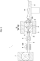
- Fig. 1 is a schematic view showing a particle beam therapy facility 100 and a particle beam therapy device 250 according to an embodiment of the present disclosure.
- the particle beam therapy facility 100 is a facility that performs therapy by using neutron rays generated by a neutron ray generating device 1 as particle beams.
- the particle beam therapy device 250 is a device that performs therapy by using neutron rays generated by the neutron ray generating device 1 as particle beams.
- the neutron ray generating device 1 is used as a neutron capture therapy apparatus that performs cancer therapy using boron neutron capture therapy (BNCT).
- BNCT boron neutron capture therapy
- the neutron ray generating device 1 includes an accelerator 2.
- the accelerator 2 accelerates particles to emit a particle beam R.
- a cyclotron, a linear accelerator, or the like may be employed as the accelerator 2.
- the particle beam R emitted from the accelerator 2 passes through a transport path 9, referred to as a beam duct, whose inside is maintained in a vacuum and allows the beam to pass through, and is transported to a target disposition portion 30.
- the target disposition portion 30 is a portion where a target 10 is disposed, and includes a mechanism that holds the target 10 in the posture for irradiation.
- the target 10 is disposed at a position facing an end portion (emission port) of the transport path 9.
- the particle beam R emitted from the accelerator 2 passes through the transport path 9 and proceeds toward the target 10 disposed at the end portion of the transport path 9.
- a plurality of electromagnets 4 (such as quadrupole electromagnets) and a scanning electromagnet 6 are provided along the transport path 9.
- the plurality of electromagnets 4 perform, for example, beam axis adjustment and the like of the particle beam R by using electromagnets.
- the scanning electromagnet 6 performs a scan with the particle beam R and performs irradiation control of the particle beam R onto the target 10.
- the scanning electromagnet 6 controls the irradiation position of the particle beam R on the target 10.
- the neutron ray generating device 1 generates the neutron rays N by irradiating the target 10 with the particle beam R and emits the neutron rays N toward the patient 50.
- the neutron ray generating device 1 includes the target 10, a shield member 8, a deceleration member 39, and a collimator 20.
- the target 10 generates the neutron rays N when irradiated with the particle beam R.
- the target 10 is a solid member formed of a material that generates the neutron rays N when irradiated with the particle beam R.
- the target 10 is formed of, for example, beryllium (Be), lithium (Li), tantalum (Ta), or tungsten (W) and has, for example, a solid disc shape with a diameter of 160 mm.
- the target 10 is not limited to a disc shape and may have other shapes.
- the deceleration member 39 decelerates the neutron rays N generated by the target 10 (reduces the energy of the neutron rays N).
- the deceleration member 39 may have a laminated structure consisting of a layer 39A that primarily decelerates fast neutrons contained in the neutron rays N and a layer 39B that primarily decelerates epithermal neutrons contained in the neutron rays N.
- the shield member 8 blocks the generated neutron rays N, gamma rays generated as a result of generating the neutron rays N, and the like to prevent their release to the outside.
- the shield member 8 is provided to surround the deceleration member 39. An upper portion and a lower portion of the shield member 8 extend to an upstream side of the particle beam R with respect to the deceleration member 39.
- the collimator 20 shapes the irradiation field of the neutron rays N and includes an irradiation port 20a through which the neutron rays N pass.
- the collimator 20 is, for example, a block-shaped member including the irradiation port 20a at its center.
- the particle beam therapy facility 100 includes an accelerator room 101, a therapy room 102, a transfer room 103, a plurality of preparation rooms 104A, 104B, and 104C, an imaging room 105, and a boron concentration measurement room 106.
- the accelerator room 101, the therapy room 102, the transfer room 103, each of the preparation rooms 104A, 104B, and 104C, the imaging room 105, and the boron concentration measurement room 106 are rooms independent of other rooms.
- An independent room is a section that is formed as a single continuous space by being partitioned from other rooms by walls.
- the accelerator room 101 is a room for primarily disposing the accelerator 2 and the transport path 9 of the aforementioned neutron ray generating device 1.
- the therapy room 102 is a room for administering therapy to the patient 50 by irradiating the patient 50 with neutron rays.
- the accelerator room 101 and the therapy room 102 are spaces partitioned by blockade walls such as concrete.
- the accelerator room 101 and the therapy room 102 are separated by a partition wall 110 of a building.
- the aforementioned collimator 20 is provided on a wall surface of the partition wall 110 on a therapy room 102 side.
- a therapy section 142 for performing therapy with neutron rays is provided in front of the collimator 20.
- the therapy section 142 includes, for example, various mechanisms required for therapy, such as a therapy table 120, which is provided in the vicinity of an outlet of the irradiation port 20a and is movable in XYZ directions with a placement member 51 placed thereon.
- the therapy table 120 is a mechanism for receiving the placement member 51, to which the patient 50 is fixed, and for disposing an affected part of the patient 50 in the vicinity of the irradiation port 20a through movement in the XYZ directions (including rotational movement).
- the therapy table 120 is liftable, lowerable, and slidable in each of the XYZ directions, is rotatable 360° around a Z axis, and is rotatable around an X axis and a Y axis by a predetermined angle.
- the therapy table 120 may be a fixed table that does not move.
- the therapy table 120 includes a single therapy room entrance 112 that is provided on a partition wall 111 on a side opposite to the accelerator room 101 among the blockade walls surrounding the therapy room 102 and that connects the therapy room 102 and the transfer room 103.
- the transfer room 103 is a room for transferring between the therapy room 102, the preparation rooms 104A, 104B, and 104C, the imaging room 105, and the boron concentration measurement room 106.
- the transfer room 103 is a room that is separated from the therapy room 102 by the partition wall 111 in a radiation-shielded state and that spreads to a side in front of the therapy room entrance 112 of the therapy room 102.
- the preparation rooms 104A, 104B, and 104C, the imaging room 105, and the boron concentration measurement room 106 are disposed to surround the transfer room 103.
- the preparation rooms 104A, 104B, and 104C, the imaging room 105, and the boron concentration measurement room 106 are disposed in an arch shape in this order from one end portion to the other end portion in a width direction of the partition wall 111.
- the preparation rooms 104A, 104B, and 104C include preparation room entrances 113 that are connected to the transfer room 103.
- the imaging room 105 includes an imaging room entrance 114 that is connected to the transfer room 103.
- the boron concentration measurement room 106 includes a measurement room entrance 116 that is connected to the transfer room 103.
- the transfer room 103 includes a single continuous space that allows communication between the therapy room entrance 112 of the therapy room 102, the preparation room entrance 113 of each of the plurality of preparation rooms 104A, 104B, and 104C, the imaging room entrance 114 of the imaging room 105, and the measurement room entrance 116 of the boron concentration measurement room 106.
- the single continuous space that couples the entrances 112, 113, 114, and 116 to each other is a space having a sufficient width and shape to allow the placement member 51 to be transported between the rooms by the same transport mechanism.
- the line of sight is not obstructed by structures that partition the space, such as walls or staircases of the building.
- the line of sight is obstructed by the transport mechanism, but the line of sight is not obstructed by structures that partition the space. Therefore, it can be said that the preparation room entrance 113 of the preparation room 104C and the therapy room entrance 112 communicate with each other through the single continuous space.
- the preparation rooms 104A, 104B, and 104C include entrances 117 on a side opposite to the transfer room 103 to allow access from corridors, rooms, and the like on the side opposite to the transfer room 103.
- the imaging room 105 includes an entrance 118 on the side opposite to the transfer room 103 to allow access from the corridors, the rooms, and the like on the side opposite to the transfer room 103.
- the boron concentration measurement room 106 includes an entrance 119 on the side opposite to the transfer room 103 to allow access from the corridors, the rooms, and the like on the side opposite to the transfer room 103.
- Fig. 3 shows a facility in which a long corridor 200 is provided between the plurality of preparation rooms 104A, 104B, and 104C and the therapy room 102.
- the preparation rooms 104A and 104C are connected to the therapy room 102 through curved corridors 201 and 202.
- the preparation room 104B is connected to the therapy room 102 through a corridor 204 including a staircase 203. Lines of sight VL2 and VL4 when viewed from the preparation room entrances 113 of the preparation rooms 104A and 104C toward the therapy room entrance 112 are obstructed by walls of the building.
- a line of sight VL3 when viewed from the preparation room entrance 113 of preparation room 104B toward the therapy room 102 is obstructed by the staircase 203 of the building. Therefore, the facility shown in Fig. 3 does not include a transfer room including a single continuous space that allows communication between the therapy room entrance 112 of the therapy room 102 and the preparation room entrance 113 of each of the plurality of preparation rooms 104A, 104B, and 104C.
- the preparation rooms 104A, 104B, and 104C are rooms for performing preparations for therapy in the therapy room 102.
- the preparation rooms 104A, 104B, and 104C are provided with preparation sections 144 for performing preparations for therapy.
- the preparation section 144 includes, for example, a table 121 on which the placement member 51 is placed, a device used for alignment, and the like.
- the table 121 is used as one component of a positioning device for the patient 50 and is movable in the XYZ directions (including rotational movement), with the placement member 51 on which the patient 50 is fixed placed thereon.
- the table 121 is liftable, lowerable, and slidable in each of the XYZ directions, is rotatable 360° around the Z axis, and is rotatable around the X axis and the Y axis by a predetermined angle.
- the state of the patient 50 in the therapy room 102 can be simulated through the alignment using the placement member 51, the table 121, and a laser and/or X-ray imaging device. Specifically, in the preparation section 144, the positions of the patient 50 and the irradiation port 20a in the therapy room 102 relative to the placement member 51 can be simulated.
- the preparations for the therapy in preparation rooms 104A, 104B, and 104C will be described. Since the neutron rays N used for therapy are diffusely released from the irradiation port 20a, the patient 50 is placed as close as possible to the irradiation port 20a. Meanwhile, a human body has a complex shape (particularly the neck). Currently, since there is no function of changing a beam irradiation direction, such as a gantry, the posture of the patient 50 is determined with respect to the fixed irradiation port 20a. Therefore, in a case of performing therapy by using the neutron ray generating device 1, the posture of the patient 50 on the placement member 51 is determined in advance.
- the patient 50 may be forced into an unnatural posture such that the patient 50 approaches the irradiation port 20a, and then, the patient 50 may be fixed to the placement member 51 by using a fixture.
- the preparation rooms 104A, 104B, and 104C are provided.
- therapy simulations are also performed in the preparation rooms 104A, 104B, and 104C.
- the simulation is tasks such as examining the fixing method of the patient 50 and creating a fixing jig for the fixation determined after the examination.
- the simulation is performed a few days before the actual therapy.
- the imaging room 105 is a room for imaging the patient 50.
- the imaging room 105 includes an imaging section 145.
- the imaging section 145 includes the table 121 and the X-ray imaging device.
- the patient 50 is imaged by, for example, using the X-ray imaging device in order to check a positioning result of the patient 50 in the preparation section 144.
- the X imaging device includes a space for disposing the patient 50 between an X-ray irradiation device and an X-ray detection device (imaging plate (photographic negative)), and imaging is performed with the patient 50 interposed therebetween.
- the imaging section 145 may have a combination of the table 121 moving in the up-down direction and the traveling X-ray imaging device, or may have a combination of the table 121 moving up and down and back and forth and the rotating X-ray imaging device.
- the imaging room 105 enables imaging of the patient 50 prepared in each of the plurality of preparation rooms 104A, 104B, and 104C. In the preparation rooms 104A, 104B, and 104C, the therapy simulations are performed, and the adjustment of the fixation position of the patient 50 and the like are performed. In the imaging room 105, the patient 50 is transported while remaining fixed, and imaging is performed to check whether the fixation position is correct.
- the boron concentration measurement room 106 is a room for measuring the boron concentration of the patient 50.
- the boron concentration measurement room 106 includes a boron concentration measurement section 146 for measuring the boron concentration.
- the boron concentration measurement section 146 includes a measurement device that measures the boron concentration of the patient 50.
- the boron concentration of the patient 50 prepared in each of the plurality of preparation rooms 104A, 104B, and 104C can be measured.
- blood collected from the patient 50 need only be provided. Therefore, the boron concentration measurement section 146 may or may not include the table 121. Even in a case where the boron concentration measurement section 146 includes the table 121, a moving mechanism or a rotating mechanism is not required.
- the boron concentration measurement room 106 may be omitted.
- the transfer room 103 is provided with a support portion 135.
- the support portion 135 is a structure provided between the therapy section 142 and the plurality of preparation sections 144.
- the support portion 135 is fixed on a floor surface of the transfer room 103.
- the support portion 135 supports a transport mechanism 130.
- the transport mechanism 130 is supported by the support portion 135 to be movable between the plurality of preparation sections 144 and the therapy section 142 and transports the patient 50 between the plurality of preparation sections 144 and the therapy section 142. That is, the transport mechanism 130 transports the patient 50 between the therapy room 102 and the preparation rooms 104A, 104B, and 104C.
- the transport mechanism 130 includes a transport arm 131 that is rotatable around a center axis CL extending in the up-down direction.
- the transport mechanism 130 rotates around the center axis CL and directs the tip of the transport arm 131 toward the desired room. Then, the transport arm 131 of the transport mechanism 130 enters the room through the entrance.
- the transport arm 131 holds the patient 50 along with the placement member 51 from inside the room and extracts the patient 50 from the room.
- the transport arm 131 rotates around the center axis CL and faces the direction of the room of the transport destination. Then, the transport arm 131 enters the room together with the placement member 51 through the entrance.
- the transport arm 131 installs the patient 50 along with the placement member 51 in the room of the transport destination.
- the transport mechanism 130 takes out the patient 50 along with the placement member 51 from the preparation room 104A and transports the patient 50 to the imaging room 105. Additionally, when the patient 50 is fixed to the placement member 51 in the preparation room 104A as the preparation for the therapy, the transport mechanism 130 takes out the patient 50 along with the placement member 51 from the preparation room 104A and transports the patient 50 to the therapy room 102.
- the transport mechanism 130 transports a certain patient 50 from the preparation room 104A to the therapy room 102. Then, the transport mechanism 130 transports, during the therapy of the patient 50 in the therapy room 102, another patient 50 from another preparation room 104B (or preparation room 104C) to another room excluding the therapy room 102.
- the other room is the imaging room 105, the boron concentration measurement room 106, or the like.
- the transport mechanism 130 transports a certain patient 50 from the preparation room 104A to the imaging room 105.
- the transport mechanism 130 transports, during the imaging of the patient 50 in the imaging room 105 or during the imaging preparation in the preparation room 104A, another patient 50 from another preparation room 104B (or preparation room 104C) to the therapy room 102.
- Fig. 4 is a diagram showing the operation timing of the particle beam therapy facility 100 throughout a day.
- Fig. 4 it is assumed that there are four preparation rooms, from the "preparation room 104A" to a "preparation room 104D", as the preparation rooms.
- the "preparation room 104D” is added to the particle beam therapy facility 100 in Fig. 1 .
- the therapy of eight patients 50, from a "patient A1” to a "patient A8” is administered in the therapy room 102, and the therapy simulations of eight patients 50, from a "patient B1" to a "patient B8", are performed.
- Fig. 4 the operation timing in each room of the particle beam therapy facility 100 is indicated by color-coded bars with patterns.
- “Infusion” means injecting a boron drug into the patient 50.
- “Positioning” means performing the task of positioning the posture of the patient 50 on the placement member 51.
- “Irradiation” means performing the therapy through irradiation with neutron rays.
- “Quit” means performing post-therapy treatments.
- Shell Preparation means performing a therapy simulation and preparing a fixing jig.
- CT means imaging the patient 50 by using a CT device.
- “Check” means checking the position of the patient 50 from the captured image.
- therapy room 102 therapy for the eight patients, the "patient A1” to the “patient A8", is performed.
- the imaging room 105 the eight patients, the "patient B1” to the “patient B8", are imaged.
- the "patient A1" to the "patient A8” and the "patient B1” to the “patient B8” are different individuals.
- the therapy simulations of the "patient A1" to the "patient A8” are completed by the previous day. It is assumed that the therapy of the "patient B1" to the "patient B8” will be performed at a later date.
- preparations and the like for the "patient A1", the “patient B2”, the “patient A5", and the “patient B7” are performed.
- preparations and the like for the "patient A2”, the “patient B4", the “patient A6", and the “patient B8” are performed.
- preparations and the like for the "patient B1", the “patient A3”, the “patient B5", and the “patient A7” are performed.
- preparations and the like for the "patient B2", the “patient A4", the “patient B6", and the “patient A8” are performed.
- the timing at which the patient 50 is transported to another room is indicated by an arrow. Further, in the item for the transfer room 103, the timing during transport is indicated by a bar.
- the therapy preparation for the "patient A1” is performed in the preparation room 104A, and after the preparation, the "patient A1” is transported to the therapy room 102 for the therapy and is then transported to the preparation room 104A for post-treatments.
- the simulation preparation for the "patient B1” is performed in the preparation room 104C, and after the preparation, the "patient B1” is transported to imaging room 105 for imaging and is then transported to the preparation room 104C for checking.
- the transport mechanism 130 transports, during the therapy of the "patient A1" in the therapy room 102, another "patient B1" from the preparation room 104C, which is different from the preparation room 104A, to the imaging room 105, which is another room excluding the therapy room 102.
- the transport mechanism 130 transports, during the imaging preparation for the "patient B1" in the preparation room 104C, another "patient A1” from another preparation room 104A to the therapy room 102.
- the preparation for the therapy of the "patient A2" starts in the preparation room 104B.
- the start of the preparation in the preparation room 104B is adjusted such that the therapy timing in the therapy room 102 for the "patient A2” does not overlap with the therapy timing in the therapy room 102 for the "patient A1".
- the preparation for the simulation of the "patient B2" starts in the preparation room 104D.
- the start of the preparation in the preparation room 104D is adjusted such that the imaging timing in the imaging room 105 for the "patient B2" does not overlap with the imaging timing in the imaging room 105 for the "patient B1".
- the imaging of the patients 50 (patients A1 to A8) for whom therapy is performed in the therapy room 102 is completed by the previous day.
- the preparation (injection) for the therapy and the therapy in the therapy room 102 may be performed on the same day.
- the patient 50 is imaged in the imaging room 105 while remaining fixed, for the final check of the patient's position immediately before the injection.
- the plurality of preparation rooms 104 are provided for a single independent therapy room 102. Therefore, when the preparation for the therapy in the therapy room 102 is being performed in a certain preparation room 104, the therapy simulation can be performed in another preparation room 104. Consequently, the facility can be downsized because the simulation room can be omitted.
- the particle beam therapy facility 100 includes the transfer room 103 for transferring between the therapy room 102 and the preparation rooms 104. Additionally, the transfer room 103 includes a single continuous space that allows communication between the therapy room entrance 112 of the therapy room 102 and the preparation room entrance 113 of each of the plurality of preparation rooms 104.
- the particle beam therapy facility 100 can quickly perform transport through the common space of the transfer room 103, regardless of which preparation room 104 the patient 50 is transported from. Accordingly, the layout between the therapy room 102 and the plurality of preparation rooms 104 can be made compact. As a result, the facility can be downsized.
- the plurality of preparation rooms 104 are provided for a single independent therapy room 102. Therefore, when the preparation for the therapy in the therapy room 102 is being performed in a certain preparation room 104, the therapy simulation can be performed in another preparation room 104. Consequently, the facility can be downsized because the simulation room can be omitted.
- the particle beam therapy facility 100 includes the transfer room 103 for transferring between the therapy room 102 and the preparation rooms 104.
- the transport mechanism 130 may be rotatable around the center axis extending in the up-down direction. Consequently, the transport mechanism 130 can quickly perform transport by rotating and directing the transport arm 131 toward the desired room.
- the plurality of preparation rooms 104 may be disposed to surround the transfer room 103. In this case, the number of preparation rooms 104 that can be disposed with respect to the area of the transfer room 103 can be increased.
- the boron concentration measurement room 106 that is independent of other rooms and is used to measure the boron concentration of the patient 50 may be further provided.
- the neutron ray generating device 1 adjusts the amount of irradiation charge based on the measurement result of the boron concentration in the collected blood.
- the measurement result of the boron concentration in the blood can be quickly obtained.
- the boron concentration measurement room 106 includes a device that measures the boron concentration through image diagnosis, the measurement can be performed simply by transporting the patient 50 without collecting blood.
- the boron concentration measurement room 106 may be omitted by disposing such a device in the imaging room 105.
- the particle beam therapy device 250 includes the support portion 135 between the therapy section 142 and the plurality of preparation sections 144.
- the particle beam therapy device 250 includes the transport mechanism 130 that is supported by the support portion 135 to be movable between the plurality of preparation sections 144 and the therapy section 142 and that transports the patient 50 between the plurality of preparation sections 144 and the therapy section 142. Therefore, the particle beam therapy device 250 can quickly perform transport by using the common transport mechanism 130 supported by the support portion 135, regardless of which preparation section 144 the patient 50 is transported from. Accordingly, the layout between the therapy section 142 and the plurality of preparation sections 144 can be made compact. As a result, the facility can be downsized.
- the transport mechanism 130 that transports the patient 50 between the therapy room 102 and the preparation rooms 104 may include the transport arm 131 that is rotatable around the center axis CL extending in the up-down direction. Consequently, the transport mechanism 130 can quickly perform transport by rotating and directing the transport arm 131 toward the desired room.
- the support portion 135 may be provided between the therapy section 142, the plurality of preparation sections 144, and the imaging section 145 for imaging the patient 50, and the transport mechanism 130 may be supported by the support portion 135 to be movable between the plurality of preparation sections 144, the imaging section 145, and the therapy section 142 and may transport the patient 50 between the plurality of preparation sections 144, the imaging section 145, and the therapy section 142.
- the particle beam therapy device 250 can quickly check the fixation position of the patient 50 by performing the therapy simulation in a certain preparation section 144 to determine the fixation position, and then transporting the patient 50 to the imaging section 145 for imaging while keeping the patient 50 fixed.
- the particle beam therapy device 250 may further include the imaging room 105 that is independent of other rooms and that is provided with the imaging section 145, and the imaging room 105 may enable the imaging of the patient 50 prepared in each of the plurality of preparation rooms 104 that are each provided with the preparation section 144.
- the particle beam therapy device 250 can quickly check the fixation position of the patient 50 by performing the therapy simulation in a certain preparation room 104 to determine the fixation position, and then transporting the patient 50 to the imaging room 105 for imaging while keeping the patient 50 fixed.
- the imaging room 105 is provided near the preparation room 104, and the plurality of preparation rooms 104 are provided for a single therapy room 102, the preparation room 104 can also be used as the simulation room.
- the preparation immediately before the therapy can be performed in the same preparation room 104 as the preparation room 104 where the simulation has been performed. In this case, since there is no need to correct alignment errors between the simulation and the actual therapy preparation, the preparation time immediately before the therapy can be shortened.
- the transport mechanism 130 that transports the patient 50 between the therapy section 142 and the preparation sections 144 may transport a first patient 50 from a first preparation section 144 to the therapy section 142 and may transport, during the therapy of the first patient 50 in the therapy section 142, a second patient 50 from a second preparation section 144 to another room excluding the therapy section 142. In this case, it is possible to proceed with the therapy preparation for another second patient 50 in another preparation section 144 simultaneously with the therapy of the first patient 50.
- the transport mechanism 130 may transport the first patient 50 from the first preparation section 144 to the imaging section 145 for performing imaging of the patient 50 and may transport, during the imaging of the first patient 50 in the imaging section 145 or during the preparation for the first patient 50 in the first preparation section 144, the second patient 50 from the second preparation section 144 to the therapy section 142. In this case, it is possible to proceed with the therapy of another second patient 50 in another preparation section 144 simultaneously with the simulation of the first patient 50 or the imaging for checking the simulation.
- Fig. 7 shows conditions of the comparative example and the example.
- a particle beam therapy facility according to the comparative example includes a therapy room, a preparation room, a simulation room, and a transport machine as one set, and includes two such sets.
- Fig. 5 shows the operation timing of the particle beam therapy facility 100 of the particle beam therapy facility according to the comparative example throughout a day.
- the number of patients that can undergo therapy in one day is six, and the number of patients that can undergo simulations is six.
- the neutron generating device may use a nuclear reactor instead of an accelerator.
- the above-described configuration of the particle beam therapy facility is merely an example and can be appropriately modified.
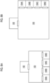
- layouts may be employed in which the preparation rooms 104 do not surround the transfer room.
Landscapes
- Health & Medical Sciences (AREA)
- Engineering & Computer Science (AREA)
- Biomedical Technology (AREA)
- Pathology (AREA)
- Nuclear Medicine, Radiotherapy & Molecular Imaging (AREA)
- Radiology & Medical Imaging (AREA)
- Life Sciences & Earth Sciences (AREA)
- Animal Behavior & Ethology (AREA)
- General Health & Medical Sciences (AREA)
- Public Health (AREA)
- Veterinary Medicine (AREA)
- Radiation-Therapy Devices (AREA)
Abstract
Description
- The present disclosure relates to a particle beam therapy facility and a particle beam therapy device.
- Boron neutron capture therapy (BNCT) using a boron compound is known as neutron capture therapy of irradiating cancer cells with neutron rays to kill the cancer cells. In the boron neutron capture therapy, boron that has been incorporated into the cancer cells in advance is irradiated with neutron rays, thereby selectively destroying the cancer cells through the scattering of the resulting heavy charged particles.
- As a device that generates neutron rays used for the aforementioned purpose, for example, a neutron ray generating device disclosed in
PTL 1 is used. The neutron ray generating device disclosed inPTL 1 performs therapy by being disposed in front of an irradiation port of neutron rays while a patient is fixed to a placement member. - [PTL 1]
Japanese Unexamined Patent Publication No. 2020-146119 - As mentioned above, in order to perform therapy with particle beams, preparations such as adjusting and fixing the patient's posture are performed in a preparation room before the therapy. Therefore, the preparation room is provided as a separate room from a therapy room. Here, in a case where a plurality of combinations of one preparation room for one therapy room are provided in order to perform preparations and therapy for a large number of patients, there is a problem that the particle beam therapy facility becomes large in size.
- Therefore, an object of the present disclosure is to provide a particle beam therapy facility and a particle beam therapy device capable of downsizing the facility.
- According to the present disclosure, there is provided a particle beam therapy facility including: a therapy room that is independent of other rooms and that is used to perform therapy with particle beams; a plurality of preparation rooms that are used to perform preparations for the therapy; and a transfer room that is independent of other rooms and that is used to transfer between the therapy room and the preparation rooms, in which the transfer room includes a single continuous space that allows communication between a therapy room entrance of the therapy room and a preparation room entrance of each of the plurality of preparation rooms.
- In the particle beam therapy facility according to the present disclosure, the plurality of preparation rooms are provided for a single independent therapy room. Therefore, when the preparation for therapy in the therapy room is being performed in a certain preparation room, a therapy simulation can be performed in another preparation room. Consequently, the facility can be downsized because a simulation room can be omitted. Here, the particle beam therapy facility includes a transfer room that is used to transfer between the therapy room and the preparation rooms. Additionally, the transfer room includes a single continuous space that allows communication between a therapy room entrance of the therapy room and a preparation room entrance of each of the plurality of preparation rooms. Therefore, the particle beam therapy facility can quickly perform transport through the common space of the transfer room, regardless of which preparation room the therapy target object is transported from. Accordingly, the layout between the therapy room and the plurality of preparation rooms can be made compact. As a result, the facility can be downsized.
- In the particle beam therapy facility, a support portion provided in the transfer room; and a transport mechanism that is supported by the support portion to be movable between the plurality of preparation rooms and the therapy room and that transports a therapy target object between the plurality of preparation rooms and the therapy room may be further provided. In this case, the particle beam therapy facility can quickly perform transport by using the common transport mechanism supported by the support portion of the transfer room, regardless of which preparation room the therapy target object is transported from. Therefore, the layout between the therapy room and the plurality of preparation rooms can be made compact. As a result, the facility can be downsized.
- The transport mechanism may be rotatable around a center axis extending in an up-down direction. Consequently, the transport mechanism can quickly perform transport by rotating and directing a transport arm toward the desired room.
- The plurality of preparation rooms may be disposed to surround the transfer room. In this case, the number of preparation rooms that can be disposed with respect to the area of the transfer room can be increased.
- A boron concentration measurement room that is independent of other rooms and that is used to measure a boron concentration of a therapy target object may be further provided. In this case, since the boron concentration of the therapy target object can be quickly measured, the number of personnel and time required for the measurement can be reduced.
- According to the present disclosure, there is provided a particle beam therapy device including: a support portion provided between a therapy section for performing therapy with particle beams and a plurality of preparation sections for performing preparations for the therapy; and a transport mechanism that is supported by the support portion to be movable between the plurality of preparation sections and the therapy section and that transports a therapy target object between the plurality of preparation sections and the therapy section.
- The particle beam therapy device according to the present disclosure includes the support portion provided between the therapy section and the plurality of preparation sections. In addition, the particle beam therapy device includes the transport mechanism that is supported by the support portion to be movable between the plurality of preparation sections and the therapy section and that transports the therapy target object between the plurality of preparation sections and the therapy section. Therefore, the particle beam therapy device can quickly perform transport by using the common transport mechanism supported by the support portion, regardless of which preparation section the therapy target object is transported from. Accordingly, the layout between the therapy section and the plurality of preparation sections can be made compact. As a result, the facility can be downsized.
- In the particle beam therapy device, a therapy room that is independent of other rooms and that is provided with the therapy section; a plurality of preparation rooms that are each provided with the preparation section; and a transfer room that is independent of other rooms, that is provided with the transport mechanism, and that is used to transfer between the therapy room and the preparation rooms may be further provided. A plurality of preparation rooms are provided for a single independent therapy room. Therefore, when the preparation for therapy in the therapy room is being performed in a certain preparation room, the therapy simulation can be performed in another preparation room. Consequently, the facility can be downsized because the simulation room can be omitted. Here, the particle beam therapy device includes the transfer room that is used to transfer between the therapy room and the preparation rooms. In addition, the transfer room is provided with the transport mechanism that transports the therapy target object between the therapy room and the preparation room. Therefore, the particle beam therapy facility can quickly perform transport by using the common transport mechanism of the transfer room, regardless of which preparation room the therapy target object is transported from. Accordingly, the layout between the therapy room and the plurality of preparation rooms can be made compact. As a result, the facility can be downsized.
- The plurality of preparation sections may be disposed to surround the transport mechanism. In this case, the number of preparation sections that can be disposed with respect to the area of the transfer room can be increased.
- The transport mechanism may include a transport arm that is rotatable around a center axis extending in an up-down direction. Consequently, the transport mechanism can quickly perform transport by rotating and directing a transport arm toward the desired room.
- The support portion may be provided between the therapy section, the plurality of preparation sections, and an imaging section for imaging the therapy target object, and the transport mechanism may be supported by the support portion to be movable between the plurality of preparation sections, the imaging section, and the therapy section and may transport the therapy target object between the plurality of preparation sections and the imaging section, and the therapy section. In this case, the particle beam therapy device can quickly check a fixation position of the therapy target object by performing the therapy simulation in a certain preparation section to determine the fixation position, and then transporting the therapy target object to the imaging section for imaging while keeping the therapy target object fixed. Additionally, since the imaging section is provided near the preparation section, the preparation immediately before the therapy can be performed in the same preparation section as the preparation section where the simulation has been performed. In this case, since there is no need to correct alignment errors between the simulation and the actual therapy preparation, the preparation time immediately before the therapy can be shortened.
- In the particle beam therapy device, an imaging room that is independent of other rooms and that is provided with the imaging section may be further provided, and the imaging room may enable imaging of the therapy target object prepared in each of the plurality of preparation rooms that are each provided with the preparation section. In this case, the particle beam therapy device can quickly check the fixation position of the therapy target object by performing the therapy simulation in a certain preparation room to determine the fixation position, and then transporting the therapy target object to the imaging room for imaging while keeping the therapy target object fixed. Additionally, since the imaging room is provided near the preparation room, the preparation immediately before the therapy can be performed in the same preparation room as the preparation room where the simulation has been performed. In this case, since there is no need to correct alignment errors between the simulation and the actual therapy preparation, the preparation time immediately before the therapy can be shortened.
- The transport mechanism may transport a first therapy target object from a first preparation section to the therapy section and may transport, during therapy of the first therapy target object in the therapy section, a second therapy target object from a second preparation section to a plurality of other preparation sections excluding the therapy section or to an imaging section for imaging the therapy target object. In this case, it is possible to proceed with the therapy preparation for the second therapy target object in another preparation section simultaneously with the therapy for the first therapy target object.
- The transport mechanism may transport a first therapy target object from a first preparation section to an imaging section for imaging the therapy target object and may transport, during imaging of the first therapy target object in the imaging section or during preparation of the first therapy target object in the first preparation section, a second therapy target object from a second preparation section to the therapy section. In this case, it is possible to proceed with therapy of another second therapy target object in another preparation room simultaneously with the simulation of the first therapy target object or the imaging for checking the simulation.
- According to the present disclosure, it is possible to provide a particle beam therapy facility and a particle beam therapy device capable of downsizing the facility.
-
-
Fig. 1 is a schematic view showing a particle beam therapy facility and a particle beam therapy device according to an embodiment of the present disclosure. -
Fig. 2 is a schematic view showing a neutron ray generating device. -
Fig. 3 is a schematic view showing a particle beam therapy facility according to a comparative example. -
Fig. 4 is a diagram showing an operation timing of the particle beam therapy facility. -
Fig. 5 is a diagram showing an operation timing of the particle beam therapy facility according to the comparative example. -
Fig. 6 is a diagram showing an operation timing of a particle beam therapy facility according to an example. -
Fig. 7 is a table comparing conditions of the comparative example and the example. -
Figs. 8A and 8B are schematic views showing particle beam therapy facilities according to modification examples. - Hereinafter, a preferred embodiment of the present disclosure will be described in detail with reference to the drawings.
-
Fig. 1 is a schematic view showing a particlebeam therapy facility 100 and a particlebeam therapy device 250 according to an embodiment of the present disclosure. The particlebeam therapy facility 100 is a facility that performs therapy by using neutron rays generated by a neutronray generating device 1 as particle beams. The particlebeam therapy device 250 is a device that performs therapy by using neutron rays generated by the neutronray generating device 1 as particle beams. The neutronray generating device 1 is used as a neutron capture therapy apparatus that performs cancer therapy using boron neutron capture therapy (BNCT). First, the configuration of the neutronray generating device 1 that functions as the neutron capture therapy apparatus will be described with reference toFig. 2 . The neutronray generating device 1 irradiates, for example, a tumor of a patient 50 (therapy target object), to which boron (10B) has been administered, with neutron rays N. - The neutron
ray generating device 1 includes anaccelerator 2. Theaccelerator 2 accelerates particles to emit a particle beam R. For example, a cyclotron, a linear accelerator, or the like may be employed as theaccelerator 2. - The particle beam R emitted from the
accelerator 2 passes through atransport path 9, referred to as a beam duct, whose inside is maintained in a vacuum and allows the beam to pass through, and is transported to atarget disposition portion 30. Thetarget disposition portion 30 is a portion where atarget 10 is disposed, and includes a mechanism that holds thetarget 10 in the posture for irradiation. In thetarget disposition portion 30, thetarget 10 is disposed at a position facing an end portion (emission port) of thetransport path 9. The particle beam R emitted from theaccelerator 2 passes through thetransport path 9 and proceeds toward thetarget 10 disposed at the end portion of thetransport path 9. A plurality of electromagnets 4 (such as quadrupole electromagnets) and ascanning electromagnet 6 are provided along thetransport path 9. The plurality ofelectromagnets 4 perform, for example, beam axis adjustment and the like of the particle beam R by using electromagnets. - The
scanning electromagnet 6 performs a scan with the particle beam R and performs irradiation control of the particle beam R onto thetarget 10. Thescanning electromagnet 6 controls the irradiation position of the particle beam R on thetarget 10. - The neutron
ray generating device 1 generates the neutron rays N by irradiating thetarget 10 with the particle beam R and emits the neutron rays N toward thepatient 50. The neutronray generating device 1 includes thetarget 10, ashield member 8, adeceleration member 39, and acollimator 20. - The
target 10 generates the neutron rays N when irradiated with the particle beam R. Thetarget 10 is a solid member formed of a material that generates the neutron rays N when irradiated with the particle beam R. Specifically, thetarget 10 is formed of, for example, beryllium (Be), lithium (Li), tantalum (Ta), or tungsten (W) and has, for example, a solid disc shape with a diameter of 160 mm. Thetarget 10 is not limited to a disc shape and may have other shapes. - The
deceleration member 39 decelerates the neutron rays N generated by the target 10 (reduces the energy of the neutron rays N). Thedeceleration member 39 may have a laminated structure consisting of alayer 39A that primarily decelerates fast neutrons contained in the neutron rays N and alayer 39B that primarily decelerates epithermal neutrons contained in the neutron rays N. - The
shield member 8 blocks the generated neutron rays N, gamma rays generated as a result of generating the neutron rays N, and the like to prevent their release to the outside. Theshield member 8 is provided to surround thedeceleration member 39. An upper portion and a lower portion of theshield member 8 extend to an upstream side of the particle beam R with respect to thedeceleration member 39. - The
collimator 20 shapes the irradiation field of the neutron rays N and includes anirradiation port 20a through which the neutron rays N pass. Thecollimator 20 is, for example, a block-shaped member including theirradiation port 20a at its center. - Next, the configuration of the particle
beam therapy facility 100 will be described with reference toFig. 1 . As shown inFig. 1 , the particlebeam therapy facility 100 includes anaccelerator room 101, atherapy room 102, atransfer room 103, a plurality ofpreparation rooms imaging room 105, and a boronconcentration measurement room 106. Theaccelerator room 101, thetherapy room 102, thetransfer room 103, each of thepreparation rooms imaging room 105, and the boronconcentration measurement room 106 are rooms independent of other rooms. An independent room is a section that is formed as a single continuous space by being partitioned from other rooms by walls. - The
accelerator room 101 is a room for primarily disposing theaccelerator 2 and thetransport path 9 of the aforementioned neutronray generating device 1. Thetherapy room 102 is a room for administering therapy to thepatient 50 by irradiating the patient 50 with neutron rays. Theaccelerator room 101 and thetherapy room 102 are spaces partitioned by blockade walls such as concrete. Theaccelerator room 101 and thetherapy room 102 are separated by apartition wall 110 of a building. Theaforementioned collimator 20 is provided on a wall surface of thepartition wall 110 on atherapy room 102 side. - In the
therapy room 102, atherapy section 142 for performing therapy with neutron rays is provided in front of thecollimator 20. Thetherapy section 142 includes, for example, various mechanisms required for therapy, such as a therapy table 120, which is provided in the vicinity of an outlet of theirradiation port 20a and is movable in XYZ directions with aplacement member 51 placed thereon. The therapy table 120 is a mechanism for receiving theplacement member 51, to which thepatient 50 is fixed, and for disposing an affected part of the patient 50 in the vicinity of theirradiation port 20a through movement in the XYZ directions (including rotational movement). The therapy table 120 is liftable, lowerable, and slidable in each of the XYZ directions, is rotatable 360° around a Z axis, and is rotatable around an X axis and a Y axis by a predetermined angle. The therapy table 120 may be a fixed table that does not move. The therapy table 120 includes a singletherapy room entrance 112 that is provided on apartition wall 111 on a side opposite to theaccelerator room 101 among the blockade walls surrounding thetherapy room 102 and that connects thetherapy room 102 and thetransfer room 103. - The
transfer room 103 is a room for transferring between thetherapy room 102, thepreparation rooms imaging room 105, and the boronconcentration measurement room 106. Thetransfer room 103 is a room that is separated from thetherapy room 102 by thepartition wall 111 in a radiation-shielded state and that spreads to a side in front of thetherapy room entrance 112 of thetherapy room 102. Thepreparation rooms imaging room 105, and the boronconcentration measurement room 106 are disposed to surround thetransfer room 103. Thepreparation rooms imaging room 105, and the boronconcentration measurement room 106 are disposed in an arch shape in this order from one end portion to the other end portion in a width direction of thepartition wall 111. - The
preparation rooms transfer room 103. Theimaging room 105 includes animaging room entrance 114 that is connected to thetransfer room 103. The boronconcentration measurement room 106 includes ameasurement room entrance 116 that is connected to thetransfer room 103. As a result, thetransfer room 103 includes a single continuous space that allows communication between thetherapy room entrance 112 of thetherapy room 102, thepreparation room entrance 113 of each of the plurality ofpreparation rooms imaging room entrance 114 of theimaging room 105, and themeasurement room entrance 116 of the boronconcentration measurement room 106. - The single continuous space that couples the
entrances placement member 51 to be transported between the rooms by the same transport mechanism. In the space, when viewed from thepreparation room entrance 113 toward the therapy room entrance 112 (for example, along a line of sight VL1), the line of sight is not obstructed by structures that partition the space, such as walls or staircases of the building. In the configuration shown inFig. 1 , when viewed from thepreparation room entrance 113 of thepreparation room 104C toward thetherapy room entrance 112, the line of sight is obstructed by the transport mechanism, but the line of sight is not obstructed by structures that partition the space. Therefore, it can be said that thepreparation room entrance 113 of thepreparation room 104C and thetherapy room entrance 112 communicate with each other through the single continuous space. - The
preparation rooms entrances 117 on a side opposite to thetransfer room 103 to allow access from corridors, rooms, and the like on the side opposite to thetransfer room 103. Theimaging room 105 includes anentrance 118 on the side opposite to thetransfer room 103 to allow access from the corridors, the rooms, and the like on the side opposite to thetransfer room 103. The boronconcentration measurement room 106 includes anentrance 119 on the side opposite to thetransfer room 103 to allow access from the corridors, the rooms, and the like on the side opposite to thetransfer room 103. -
Fig. 3 shows a facility in which along corridor 200 is provided between the plurality ofpreparation rooms therapy room 102. Thepreparation rooms therapy room 102 throughcurved corridors preparation room 104B is connected to thetherapy room 102 through acorridor 204 including astaircase 203. Lines of sight VL2 and VL4 when viewed from the preparation room entrances 113 of thepreparation rooms therapy room entrance 112 are obstructed by walls of the building. A line of sight VL3 when viewed from thepreparation room entrance 113 ofpreparation room 104B toward thetherapy room 102 is obstructed by thestaircase 203 of the building. Therefore, the facility shown inFig. 3 does not include a transfer room including a single continuous space that allows communication between thetherapy room entrance 112 of thetherapy room 102 and thepreparation room entrance 113 of each of the plurality ofpreparation rooms - The
preparation rooms therapy room 102. Thepreparation rooms preparation sections 144 for performing preparations for therapy. Thepreparation section 144 includes, for example, a table 121 on which theplacement member 51 is placed, a device used for alignment, and the like. The table 121 is used as one component of a positioning device for thepatient 50 and is movable in the XYZ directions (including rotational movement), with theplacement member 51 on which thepatient 50 is fixed placed thereon. The table 121 is liftable, lowerable, and slidable in each of the XYZ directions, is rotatable 360° around the Z axis, and is rotatable around the X axis and the Y axis by a predetermined angle. In thepreparation section 144, the state of the patient 50 in thetherapy room 102 can be simulated through the alignment using theplacement member 51, the table 121, and a laser and/or X-ray imaging device. Specifically, in thepreparation section 144, the positions of thepatient 50 and theirradiation port 20a in thetherapy room 102 relative to theplacement member 51 can be simulated. - Here, the preparations for the therapy in
preparation rooms irradiation port 20a, thepatient 50 is placed as close as possible to theirradiation port 20a. Meanwhile, a human body has a complex shape (particularly the neck). Currently, since there is no function of changing a beam irradiation direction, such as a gantry, the posture of thepatient 50 is determined with respect to the fixedirradiation port 20a. Therefore, in a case of performing therapy by using the neutronray generating device 1, the posture of the patient 50 on theplacement member 51 is determined in advance. In particular, thepatient 50 may be forced into an unnatural posture such that the patient 50 approaches theirradiation port 20a, and then, thepatient 50 may be fixed to theplacement member 51 by using a fixture. In order to perform these therapy preparations, thepreparation rooms preparation rooms patient 50 and creating a fixing jig for the fixation determined after the examination. The simulation is performed a few days before the actual therapy. - The
imaging room 105 is a room for imaging thepatient 50. Theimaging room 105 includes animaging section 145. Theimaging section 145 includes the table 121 and the X-ray imaging device. In theimaging section 145, thepatient 50 is imaged by, for example, using the X-ray imaging device in order to check a positioning result of the patient 50 in thepreparation section 144. The X imaging device includes a space for disposing the patient 50 between an X-ray irradiation device and an X-ray detection device (imaging plate (photographic negative)), and imaging is performed with the patient 50 interposed therebetween. Theimaging section 145 may have a combination of the table 121 moving in the up-down direction and the traveling X-ray imaging device, or may have a combination of the table 121 moving up and down and back and forth and the rotating X-ray imaging device. Theimaging room 105 enables imaging of the patient 50 prepared in each of the plurality ofpreparation rooms preparation rooms patient 50 and the like are performed. In theimaging room 105, thepatient 50 is transported while remaining fixed, and imaging is performed to check whether the fixation position is correct. - The boron
concentration measurement room 106 is a room for measuring the boron concentration of thepatient 50. The boronconcentration measurement room 106 includes a boronconcentration measurement section 146 for measuring the boron concentration. The boronconcentration measurement section 146 includes a measurement device that measures the boron concentration of thepatient 50. In the boronconcentration measurement section 146, the boron concentration of the patient 50 prepared in each of the plurality ofpreparation rooms concentration measurement section 146, blood collected from the patient 50 need only be provided. Therefore, the boronconcentration measurement section 146 may or may not include the table 121. Even in a case where the boronconcentration measurement section 146 includes the table 121, a moving mechanism or a rotating mechanism is not required. The boronconcentration measurement room 106 may be omitted. - The
transfer room 103 is provided with asupport portion 135. Thesupport portion 135 is a structure provided between thetherapy section 142 and the plurality ofpreparation sections 144. Thesupport portion 135 is fixed on a floor surface of thetransfer room 103. Thesupport portion 135 supports atransport mechanism 130. Thetransport mechanism 130 is supported by thesupport portion 135 to be movable between the plurality ofpreparation sections 144 and thetherapy section 142 and transports the patient 50 between the plurality ofpreparation sections 144 and thetherapy section 142. That is, thetransport mechanism 130 transports the patient 50 between thetherapy room 102 and thepreparation rooms - The
transport mechanism 130 includes atransport arm 131 that is rotatable around a center axis CL extending in the up-down direction. Thetransport mechanism 130 rotates around the center axis CL and directs the tip of thetransport arm 131 toward the desired room. Then, thetransport arm 131 of thetransport mechanism 130 enters the room through the entrance. Thetransport arm 131 holds thepatient 50 along with theplacement member 51 from inside the room and extracts the patient 50 from the room. Next, thetransport arm 131 rotates around the center axis CL and faces the direction of the room of the transport destination. Then, thetransport arm 131 enters the room together with theplacement member 51 through the entrance. Thetransport arm 131 installs thepatient 50 along with theplacement member 51 in the room of the transport destination. - For example, when the
patient 50 is fixed to theplacement member 51 in thepreparation room 104A for the therapy simulation of thepatient 50, thetransport mechanism 130 takes out thepatient 50 along with theplacement member 51 from thepreparation room 104A and transports the patient 50 to theimaging room 105. Additionally, when thepatient 50 is fixed to theplacement member 51 in thepreparation room 104A as the preparation for the therapy, thetransport mechanism 130 takes out thepatient 50 along with theplacement member 51 from thepreparation room 104A and transports the patient 50 to thetherapy room 102. - Further, the
transport mechanism 130 transports acertain patient 50 from thepreparation room 104A to thetherapy room 102. Then, thetransport mechanism 130 transports, during the therapy of the patient 50 in thetherapy room 102, another patient 50 from anotherpreparation room 104B (orpreparation room 104C) to another room excluding thetherapy room 102. The other room is theimaging room 105, the boronconcentration measurement room 106, or the like. - In addition, the
transport mechanism 130 transports acertain patient 50 from thepreparation room 104A to theimaging room 105. Thetransport mechanism 130 transports, during the imaging of the patient 50 in theimaging room 105 or during the imaging preparation in thepreparation room 104A, another patient 50 from anotherpreparation room 104B (orpreparation room 104C) to thetherapy room 102. - Next, an example of the operation of the particle
beam therapy facility 100 will be described with reference toFig. 4. Fig. 4 is a diagram showing the operation timing of the particlebeam therapy facility 100 throughout a day. InFig. 4 , it is assumed that there are four preparation rooms, from the "preparation room 104A" to a "preparation room 104D", as the preparation rooms. Here, it is assumed that the "preparation room 104D" is added to the particlebeam therapy facility 100 inFig. 1 . Further, it is assumed that the therapy of eightpatients 50, from a "patient A1" to a "patient A8", is administered in thetherapy room 102, and the therapy simulations of eightpatients 50, from a "patient B1" to a "patient B8", are performed. InFig. 4 , the operation timing in each room of the particlebeam therapy facility 100 is indicated by color-coded bars with patterns. Among these, "Infusion" means injecting a boron drug into thepatient 50. "Positioning" means performing the task of positioning the posture of the patient 50 on theplacement member 51. "Irradiation" means performing the therapy through irradiation with neutron rays. "Quit" means performing post-therapy treatments. "Shell Preparation" means performing a therapy simulation and preparing a fixing jig. "CT" means imaging thepatient 50 by using a CT device. "Check" means checking the position of the patient 50 from the captured image. - In the
therapy room 102, therapy for the eight patients, the "patient A1" to the "patient A8", is performed. In theimaging room 105, the eight patients, the "patient B1" to the "patient B8", are imaged. The "patient A1" to the "patient A8" and the "patient B1" to the "patient B8" are different individuals. In addition, it is assumed that the therapy simulations of the "patient A1" to the "patient A8" are completed by the previous day. It is assumed that the therapy of the "patient B1" to the "patient B8" will be performed at a later date. In thepreparation room 104A, preparations and the like (preparations for therapy or simulations for creating the fixing jig) for the "patient A1", the "patient B2", the "patient A5", and the "patient B7" are performed. In thepreparation room 104B, preparations and the like for the "patient A2", the "patient B4", the "patient A6", and the "patient B8" are performed. In thepreparation room 104C, preparations and the like for the "patient B1", the "patient A3", the "patient B5", and the "patient A7" are performed. In thepreparation room 104D, preparations and the like for the "patient B2", the "patient A4", the "patient B6", and the "patient A8" are performed. InFig. 4 , the timing at which thepatient 50 is transported to another room is indicated by an arrow. Further, in the item for thetransfer room 103, the timing during transport is indicated by a bar. - First, the therapy preparation for the "patient A1" is performed in the
preparation room 104A, and after the preparation, the "patient A1" is transported to thetherapy room 102 for the therapy and is then transported to thepreparation room 104A for post-treatments. Simultaneously, the simulation preparation for the "patient B1" is performed in thepreparation room 104C, and after the preparation, the "patient B1" is transported toimaging room 105 for imaging and is then transported to thepreparation room 104C for checking. Thetransport mechanism 130 transports, during the therapy of the "patient A1" in thetherapy room 102, another "patient B1" from thepreparation room 104C, which is different from thepreparation room 104A, to theimaging room 105, which is another room excluding thetherapy room 102. Alternatively, thetransport mechanism 130 transports, during the imaging preparation for the "patient B1" in thepreparation room 104C, another "patient A1" from anotherpreparation room 104A to thetherapy room 102. - After a predetermined time has elapsed from the start of the preparation for the "patient A1" in the
preparation room 104A, the preparation for the therapy of the "patient A2" starts in thepreparation room 104B. The start of the preparation in thepreparation room 104B is adjusted such that the therapy timing in thetherapy room 102 for the "patient A2" does not overlap with the therapy timing in thetherapy room 102 for the "patient A1". Meanwhile, after a predetermined time has elapsed from the start of the simulation in thepreparation room 104C for the "patient B1", the preparation for the simulation of the "patient B2" starts in thepreparation room 104D. The start of the preparation in thepreparation room 104D is adjusted such that the imaging timing in theimaging room 105 for the "patient B2" does not overlap with the imaging timing in theimaging room 105 for the "patient B1". - Subsequently, in a similar manner, the preparation for the therapy and the therapy are performed in the order of the "patient A3", the "patient A4", ..., and the preparation for the simulation and the imaging are performed in the order of the "patient B3", the "patient B4" ....
- In the example shown in
Fig. 4 , the imaging of the patients 50 (patients A1 to A8) for whom therapy is performed in thetherapy room 102 is completed by the previous day. However, after thepatient 50 is imaged in theimaging room 105, the preparation (injection) for the therapy and the therapy in thetherapy room 102 may be performed on the same day. In this case, thepatient 50 is imaged in theimaging room 105 while remaining fixed, for the final check of the patient's position immediately before the injection. - Next, the operations and effects of the particle
beam therapy facility 100 according to the present embodiment will be described. - In the particle
beam therapy facility 100 according to the present embodiment, the plurality of preparation rooms 104 are provided for a singleindependent therapy room 102. Therefore, when the preparation for the therapy in thetherapy room 102 is being performed in a certain preparation room 104, the therapy simulation can be performed in another preparation room 104. Consequently, the facility can be downsized because the simulation room can be omitted. Here, the particlebeam therapy facility 100 includes thetransfer room 103 for transferring between thetherapy room 102 and the preparation rooms 104. Additionally, thetransfer room 103 includes a single continuous space that allows communication between thetherapy room entrance 112 of thetherapy room 102 and thepreparation room entrance 113 of each of the plurality of preparation rooms 104. Therefore, the particlebeam therapy facility 100 can quickly perform transport through the common space of thetransfer room 103, regardless of which preparation room 104 thepatient 50 is transported from. Accordingly, the layout between thetherapy room 102 and the plurality of preparation rooms 104 can be made compact. As a result, the facility can be downsized. - In the particle
beam therapy facility 100 according to the present embodiment, the plurality of preparation rooms 104 are provided for a singleindependent therapy room 102. Therefore, when the preparation for the therapy in thetherapy room 102 is being performed in a certain preparation room 104, the therapy simulation can be performed in another preparation room 104. Consequently, the facility can be downsized because the simulation room can be omitted. Here, the particlebeam therapy facility 100 includes thetransfer room 103 for transferring between thetherapy room 102 and the preparation rooms 104. In addition, the particlebeam therapy facility 100 may further include thesupport portion 135 provided in thetransfer room 103, and thetransport mechanism 130 that is supported by thesupport portion 135 to be movable between the plurality of preparation rooms 104 and thetherapy room 102 and that transports the patient 50 between the plurality of preparation rooms 104 and thetherapy room 102. Therefore, the particlebeam therapy facility 100 can quickly perform transport by using thecommon transport mechanism 130 supported by thesupport portion 135 of thetransfer room 103, regardless of which preparation room 104 thepatient 50 is transported from. Accordingly, the layout between thetherapy room 102 and the plurality of preparation rooms 104 can be made compact. As a result, the facility can be downsized. - In the particle
beam therapy facility 100, thetransport mechanism 130 may be rotatable around the center axis extending in the up-down direction. Consequently, thetransport mechanism 130 can quickly perform transport by rotating and directing thetransport arm 131 toward the desired room. - In the particle
beam therapy facility 100, the plurality of preparation rooms 104 may be disposed to surround thetransfer room 103. In this case, the number of preparation rooms 104 that can be disposed with respect to the area of thetransfer room 103 can be increased. - In the particle
beam therapy facility 100, the boronconcentration measurement room 106 that is independent of other rooms and is used to measure the boron concentration of the patient 50 may be further provided. In this case, since the boron concentration can be quickly measured by collecting blood from thepatient 50, the number of personnel and the time required for the measurement can be reduced. That is, the neutronray generating device 1 adjusts the amount of irradiation charge based on the measurement result of the boron concentration in the collected blood. In the boronconcentration measurement room 106, the measurement result of the boron concentration in the blood can be quickly obtained. In a case where the boronconcentration measurement room 106 includes a device that measures the boron concentration through image diagnosis, the measurement can be performed simply by transporting thepatient 50 without collecting blood. The boronconcentration measurement room 106 may be omitted by disposing such a device in theimaging room 105. - The particle
beam therapy device 250 according to the present embodiment includes thesupport portion 135 between thetherapy section 142 and the plurality ofpreparation sections 144. In addition, the particlebeam therapy device 250 includes thetransport mechanism 130 that is supported by thesupport portion 135 to be movable between the plurality ofpreparation sections 144 and thetherapy section 142 and that transports the patient 50 between the plurality ofpreparation sections 144 and thetherapy section 142. Therefore, the particlebeam therapy device 250 can quickly perform transport by using thecommon transport mechanism 130 supported by thesupport portion 135, regardless of whichpreparation section 144 thepatient 50 is transported from. Accordingly, the layout between thetherapy section 142 and the plurality ofpreparation sections 144 can be made compact. As a result, the facility can be downsized. - In the particle
beam therapy device 250, the plurality ofpreparation sections 144 may be disposed to surround thetransfer room 103. In this case, the number ofpreparation sections 144 that can be disposed with respect to the area of thetransfer room 103 can be increased. - In the particle
beam therapy device 250, thetransport mechanism 130 that transports the patient 50 between thetherapy room 102 and the preparation rooms 104 may include thetransport arm 131 that is rotatable around the center axis CL extending in the up-down direction. Consequently, thetransport mechanism 130 can quickly perform transport by rotating and directing thetransport arm 131 toward the desired room. - In the particle
beam therapy device 250, thesupport portion 135 may be provided between thetherapy section 142, the plurality ofpreparation sections 144, and theimaging section 145 for imaging thepatient 50, and thetransport mechanism 130 may be supported by thesupport portion 135 to be movable between the plurality ofpreparation sections 144, theimaging section 145, and thetherapy section 142 and may transport the patient 50 between the plurality ofpreparation sections 144, theimaging section 145, and thetherapy section 142. In this case, the particlebeam therapy device 250 can quickly check the fixation position of the patient 50 by performing the therapy simulation in acertain preparation section 144 to determine the fixation position, and then transporting the patient 50 to theimaging section 145 for imaging while keeping the patient 50 fixed. Additionally, since theimaging section 145 is provided near the preparation section, and the plurality ofpreparation sections 144 are provided for asingle therapy section 142, the preparation room 104 can also be used as the simulation room. In this way, since there is a time margin, the preparation immediately before the therapy can be performed in thesame preparation section 144 as thepreparation section 144 where the simulation has been performed. In this case, since there is no need to correct alignment errors between the simulation and the actual therapy preparation, the preparation time immediately before the therapy can be shortened. - The particle
beam therapy device 250 may further include theimaging room 105 that is independent of other rooms and that is provided with theimaging section 145, and theimaging room 105 may enable the imaging of the patient 50 prepared in each of the plurality of preparation rooms 104 that are each provided with thepreparation section 144. In this case, the particlebeam therapy device 250 can quickly check the fixation position of the patient 50 by performing the therapy simulation in a certain preparation room 104 to determine the fixation position, and then transporting the patient 50 to theimaging room 105 for imaging while keeping the patient 50 fixed. Additionally, since theimaging room 105 is provided near the preparation room 104, and the plurality of preparation rooms 104 are provided for asingle therapy room 102, the preparation room 104 can also be used as the simulation room. In this way, since there is a time margin, the preparation immediately before the therapy can be performed in the same preparation room 104 as the preparation room 104 where the simulation has been performed. In this case, since there is no need to correct alignment errors between the simulation and the actual therapy preparation, the preparation time immediately before the therapy can be shortened. - In the particle
beam therapy device 250, thetransport mechanism 130 that transports the patient 50 between thetherapy section 142 and thepreparation sections 144 may transport afirst patient 50 from afirst preparation section 144 to thetherapy section 142 and may transport, during the therapy of thefirst patient 50 in thetherapy section 142, asecond patient 50 from asecond preparation section 144 to another room excluding thetherapy section 142. In this case, it is possible to proceed with the therapy preparation for anothersecond patient 50 in anotherpreparation section 144 simultaneously with the therapy of thefirst patient 50. - In the particle
beam therapy device 250, thetransport mechanism 130 may transport thefirst patient 50 from thefirst preparation section 144 to theimaging section 145 for performing imaging of thepatient 50 and may transport, during the imaging of thefirst patient 50 in theimaging section 145 or during the preparation for thefirst patient 50 in thefirst preparation section 144, thesecond patient 50 from thesecond preparation section 144 to thetherapy section 142. In this case, it is possible to proceed with the therapy of anothersecond patient 50 in anotherpreparation section 144 simultaneously with the simulation of thefirst patient 50 or the imaging for checking the simulation. - A comparison will be made between a comparative example shown in
Fig. 5 and an example shown inFig. 6 .Fig. 7 shows conditions of the comparative example and the example. As shown inFig. 7 , a particle beam therapy facility according to the comparative example includes a therapy room, a preparation room, a simulation room, and a transport machine as one set, and includes two such sets.Fig. 5 shows the operation timing of the particlebeam therapy facility 100 of the particle beam therapy facility according to the comparative example throughout a day. As shown inFigs. 5 and7 , in the comparative example, the number of patients that can undergo therapy in one day is six, and the number of patients that can undergo simulations is six.Fig. 6 is a diagram showing the operation timing of the particlebeam therapy facility 100 according to the example and is a diagram showing the content ofFig. 4 in a manner that can be easily compared withFig. 5 . In the example, since the four preparation rooms can be used for both the preparation immediately before the therapy and the simulation, the waiting time per patient can be shortened. Additionally, since the preparation immediately before the therapy can be performed in the preparation room where the simulation has been performed, there is no need to correct alignment errors caused by using facilities in different rooms, and consequently, the "Positioning" time can be shortened as compared with the comparative example. Accordingly, as shown inFigs. 6 and7 , in the example, the number of patients that can undergo therapy in one day is eight, and the number of patients that can undergo simulations is eight, which is more than the number in the comparative example. - As described above, in the example, by providing the
common transport mechanism 130 in thetransfer room 103, it is not necessary to dispose the transport mechanism for each of the preparation rooms 104, which allows for a lower cost configuration of the facility. In addition, when one preparation room is provided for one therapy room as in the comparative example, it naturally becomes necessary to provide a plurality of therapy rooms. On the other hand, in the example, there is no need to provide an additional therapy room. That is, since there is no need to newly provide an additional irradiation port or an additional particle beam transport line to the irradiation port, significant reductions in devices and facility downsizing can be achieved, thereby resulting in lower introduction and maintenance costs. - The present disclosure is not limited to the above-described embodiment.
- For example, the neutron generating device may use a nuclear reactor instead of an accelerator.
- For example, the above-described configuration of the particle beam therapy facility is merely an example and can be appropriately modified. For example, as shown in
Figs. 8A and 8B , layouts may be employed in which the preparation rooms 104 do not surround the transfer room. -
- 100
- particle beam therapy facility
- 102
- therapy room
- 103
- transfer room
- 104
- preparation room
- 105
- imaging room
- 106
- boron concentration measurement room
- 142
- therapy section
- 144
- preparation section
- 145
- imaging section
- 130
- transport mechanism
- 131
- transport arm
- 135
- support portion
Claims (13)
- A particle beam therapy facility comprising:a therapy room that is independent of other rooms and that is used to perform therapy with particle beams;a plurality of preparation rooms that are used to perform preparations for the therapy; anda transfer room that is independent of other rooms and that is used to transfer between the therapy room and the preparation rooms,wherein the transfer room includes a single continuous space that allows communication between a therapy room entrance of the therapy room and a preparation room entrance of each of the plurality of preparation rooms.
- The particle beam therapy facility according to claim 1, further comprising:a support portion provided in the transfer room; anda transport mechanism that is supported by the support portion to be movable between the plurality of preparation rooms and the therapy room and that transports a therapy target object between the plurality of preparation rooms and the therapy room.
- The particle beam therapy facility according to claim 2,
wherein the transport mechanism is rotatable around a center axis extending in an up-down direction. - The particle beam therapy facility according to claim 1,
wherein the plurality of preparation rooms are disposed to surround the transfer room. - The particle beam therapy facility according to claim 1, further comprising:
a boron concentration measurement room that is independent of other rooms and that is used to measure a boron concentration of a therapy target object. - A particle beam therapy device comprising:a support portion provided between a therapy section for performing therapy with particle beams and a plurality of preparation sections for performing preparations for the therapy; anda transport mechanism that is supported by the support portion to be movable between the plurality of preparation sections and the therapy section and that transports a therapy target object between the plurality of preparation sections and the therapy section.
- The particle beam therapy device according to claim 6, further comprising:a therapy room that is independent of other rooms and that is provided with the therapy section;a plurality of preparation rooms that are each provided with the preparation section; anda transfer room that is independent of other rooms, that is provided with the transport mechanism, and that is used to transfer between the therapy room and the preparation rooms.
- The particle beam therapy device according to claim 6,
wherein the plurality of preparation sections are disposed to surround the transport mechanism. - The particle beam therapy device according to claim 6,
wherein the transport mechanism includes a transport arm that is rotatable around a center axis extending in an up-down direction. - The particle beam therapy device according to claim 6,wherein the support portion is provided between the therapy section, the plurality of preparation sections, and an imaging section for imaging the therapy target object, andthe transport mechanism is supported by the support portion to be movable between the plurality of preparation sections, the imaging section, and the therapy section and transports the therapy target object between the plurality of preparation sections and the imaging section, and the therapy section.
- The particle beam therapy device according to claim 10, further comprising:an imaging room that is independent of other rooms and that is provided with the imaging section,wherein the imaging room enables imaging of the therapy target object prepared in each of the plurality of preparation rooms that are each provided with the preparation section.
- The particle beam therapy facility according to claim 6,
wherein the transport mechanismtransports a first therapy target object from a first preparation section to the therapy section, andtransports, during therapy of the first therapy target object in the therapy section, a second therapy target object from a second preparation section to a plurality of other preparation sections excluding the therapy section or to an imaging section for imaging the therapy target object. - The particle beam therapy facility according to claim 6,
wherein the transport mechanismtransports a first therapy target object from a first preparation section to an imaging section for imaging the therapy target object, andtransports, during imaging of the first therapy target object in the imaging section or during preparation of the first therapy target object in the first preparation section, a second therapy target object from a second preparation section to the therapy section.
Applications Claiming Priority (2)
| Application Number | Priority Date | Filing Date | Title |
|---|---|---|---|
| JP2022029191 | 2022-02-28 | ||
| PCT/JP2023/007355 WO2023163220A1 (en) | 2022-02-28 | 2023-02-28 | Particle beam therapy facility and particle beam therapy device |
Publications (2)
| Publication Number | Publication Date |
|---|---|
| EP4487905A1 true EP4487905A1 (en) | 2025-01-08 |
| EP4487905A4 EP4487905A4 (en) | 2025-05-07 |
Family
ID=87766290
Family Applications (1)
| Application Number | Title | Priority Date | Filing Date |
|---|---|---|---|
| EP23760218.0A Pending EP4487905A4 (en) | 2022-02-28 | 2023-02-28 | PARTICLE BEAM THERAPY SYSTEM AND PARTICLE BEAM THERAPY DEVICE |
Country Status (5)
| Country | Link |
|---|---|
| US (1) | US20240416149A1 (en) |
| EP (1) | EP4487905A4 (en) |
| JP (1) | JPWO2023163220A1 (en) |
| CN (1) | CN118785949A (en) |
| WO (1) | WO2023163220A1 (en) |
Families Citing this family (1)
| Publication number | Priority date | Publication date | Assignee | Title |
|---|---|---|---|---|
| CN115569310B (en) * | 2022-09-01 | 2023-05-30 | 中国科学院近代物理研究所 | An Irradiation Terminal Based on Combined Rotating Beamline and Its Application |
Family Cites Families (6)
| Publication number | Priority date | Publication date | Assignee | Title |
|---|---|---|---|---|
| DE102004048210A1 (en) * | 2004-09-30 | 2006-01-12 | Siemens Ag | Radiation session performing method for use in radiation therapy, involves transporting patient in immobilized state between radiation room and immobilization station or remobilization station using transporting unit |
| DE102006057626B3 (en) * | 2006-12-05 | 2007-12-27 | Michael Koch | Radiotherapy system for treating tumor of patient, has spatially separated storage areas connected with therapy area by track sections, and conveying unit that is track guided and arranged between areas and is displaceable along sections |
| US20090154645A1 (en) * | 2007-05-24 | 2009-06-18 | Leon Lifshitz | Teletherapy treatment center |
| US9662256B2 (en) * | 2012-07-31 | 2017-05-30 | Varian Medical Systems Uk Limited | Patient positioning and support systems |
| JP6538423B2 (en) * | 2015-05-25 | 2019-07-03 | 株式会社東芝 | Therapeutic apparatus for boron neutron capture therapy and control method thereof |
| JP7287800B2 (en) | 2019-03-11 | 2023-06-06 | 住友重機械工業株式会社 | Neutron capture therapy system |
-
2023
- 2023-02-28 EP EP23760218.0A patent/EP4487905A4/en active Pending
- 2023-02-28 WO PCT/JP2023/007355 patent/WO2023163220A1/en not_active Ceased
- 2023-02-28 CN CN202380024128.9A patent/CN118785949A/en active Pending
- 2023-02-28 JP JP2024503318A patent/JPWO2023163220A1/ja active Pending
-
2024
- 2024-08-26 US US18/815,206 patent/US20240416149A1/en active Pending
Also Published As
| Publication number | Publication date |
|---|---|
| US20240416149A1 (en) | 2024-12-19 |
| WO2023163220A1 (en) | 2023-08-31 |
| CN118785949A (en) | 2024-10-15 |
| JPWO2023163220A1 (en) | 2023-08-31 |
| EP4487905A4 (en) | 2025-05-07 |
Similar Documents
| Publication | Publication Date | Title |
|---|---|---|
| CN104080516B (en) | Radiation systems with minimal or no shielding requirements for buildings | |
| JP4616843B2 (en) | Multi-chamber irradiation treatment system | |
| EP1885452B1 (en) | Small field intensity modulated radiation therapy machine | |
| AU2004220539B8 (en) | Apparatus and process for dose-guided radiotherapy | |
| US10688318B2 (en) | Radiographic imaging apparatus and particle beam therapy system | |
| CN104968394B (en) | Particle ray rotary irradiation device and particle-beam therapeutic apparatus | |
| US20040162457A1 (en) | Antiproton production and delivery for imaging and termination of undersirable cells | |
| US12070626B2 (en) | Proton therapy gantry | |
| TW201318663A (en) | Charged particle beam irradiation system, and charged particle beam irradiation planning method | |
| US11247073B2 (en) | Particle radiation therapy apparatus | |
| JP6009654B2 (en) | Particle beam irradiation room and particle beam therapy system | |
| US20240416149A1 (en) | Particle beam therapy facility and particle beam therapy device | |
| US20250018226A1 (en) | Neutron capture therapy apparatus | |
| JP2013013613A (en) | Charged particle beam irradiation device | |
| JP2024095196A (en) | Neutron capture therapy device and treatment bed | |
| Adler | W90 |
Legal Events
| Date | Code | Title | Description |
|---|---|---|---|
| STAA | Information on the status of an ep patent application or granted ep patent |
Free format text: STATUS: THE INTERNATIONAL PUBLICATION HAS BEEN MADE |
|
| PUAI | Public reference made under article 153(3) epc to a published international application that has entered the european phase |
Free format text: ORIGINAL CODE: 0009012 |
|
| STAA | Information on the status of an ep patent application or granted ep patent |
Free format text: STATUS: REQUEST FOR EXAMINATION WAS MADE |
|
| 17P | Request for examination filed |
Effective date: 20240819 |
|
| AK | Designated contracting states |
Kind code of ref document: A1 Designated state(s): AL AT BE BG CH CY CZ DE DK EE ES FI FR GB GR HR HU IE IS IT LI LT LU LV MC ME MK MT NL NO PL PT RO RS SE SI SK SM TR |
|
| STAA | Information on the status of an ep patent application or granted ep patent |
Free format text: STATUS: EXAMINATION IS IN PROGRESS |
|
| A4 | Supplementary search report drawn up and despatched |
Effective date: 20250409 |
|
| RIC1 | Information provided on ipc code assigned before grant |
Ipc: A61N 5/10 20060101AFI20250403BHEP |
|
| 17Q | First examination report despatched |
Effective date: 20250423 |
|
| DAV | Request for validation of the european patent (deleted) | ||
| DAX | Request for extension of the european patent (deleted) |