EP4487890A1 - Thin wall cannula - Google Patents
Thin wall cannula Download PDFInfo
- Publication number
- EP4487890A1 EP4487890A1 EP23183866.5A EP23183866A EP4487890A1 EP 4487890 A1 EP4487890 A1 EP 4487890A1 EP 23183866 A EP23183866 A EP 23183866A EP 4487890 A1 EP4487890 A1 EP 4487890A1
- Authority
- EP
- European Patent Office
- Prior art keywords
- cannula
- sidewall
- hydrodynamic
- needle
- diameter
- Prior art date
- Legal status (The legal status is an assumption and is not a legal conclusion. Google has not performed a legal analysis and makes no representation as to the accuracy of the status listed.)
- Pending
Links
Images

Classifications
-
- A—HUMAN NECESSITIES
- A61—MEDICAL OR VETERINARY SCIENCE; HYGIENE
- A61M—DEVICES FOR INTRODUCING MEDIA INTO, OR ONTO, THE BODY; DEVICES FOR TRANSDUCING BODY MEDIA OR FOR TAKING MEDIA FROM THE BODY; DEVICES FOR PRODUCING OR ENDING SLEEP OR STUPOR
- A61M5/00—Devices for bringing media into the body in a subcutaneous, intra-vascular or intramuscular way; Accessories therefor, e.g. filling or cleaning devices, arm-rests
- A61M5/178—Syringes
- A61M5/31—Details
- A61M5/32—Needles; Details of needles pertaining to their connection with syringe or hub; Accessories for bringing the needle into, or holding the needle on, the body; Devices for protection of needles
-
- A—HUMAN NECESSITIES
- A61—MEDICAL OR VETERINARY SCIENCE; HYGIENE
- A61M—DEVICES FOR INTRODUCING MEDIA INTO, OR ONTO, THE BODY; DEVICES FOR TRANSDUCING BODY MEDIA OR FOR TAKING MEDIA FROM THE BODY; DEVICES FOR PRODUCING OR ENDING SLEEP OR STUPOR
- A61M5/00—Devices for bringing media into the body in a subcutaneous, intra-vascular or intramuscular way; Accessories therefor, e.g. filling or cleaning devices, arm-rests
- A61M5/178—Syringes
- A61M5/31—Details
- A61M5/32—Needles; Details of needles pertaining to their connection with syringe or hub; Accessories for bringing the needle into, or holding the needle on, the body; Devices for protection of needles
- A61M5/329—Needles; Details of needles pertaining to their connection with syringe or hub; Accessories for bringing the needle into, or holding the needle on, the body; Devices for protection of needles characterised by features of the needle shaft
Definitions
- the present disclosure relates to cannulas for syringes and other medical devices.
- Cannulas are a ubiquitous component of modern medical care. Cannulas are used for example, to pierce a patient's skin to create a vascular access site for the administration of medicaments and other fluids (e.g. saline), or to withdraw blood from the patient.
- the outer diameter of cannulas is desirably minimized.
- the lumen of the cannula must be of sufficient diameter to allow the medicament or other fluid to flow through the cannula at an adequate rate, whatever the viscosity of the injected drug. As such, it is desirable to produce cannula with thin sidewalls to minimize the outer diameter while maximizing the inner diameter.
- Embodiments of the present disclosure are directed to a medical injection cannula configured for use with a syringe.
- the cannula includes a sidewall defining a lumen and having a proximal end and a distal end, and a beveled tip defining an opening to the lumen, wherein a length-to-diameter ratio of the cannula is defined by a ratio L hydrodynamic theoretical needle D needle _ inner 4 , wherein L hydrodynamic theoretical needle is a theoretical hydrodynamic length of the cannula, and D needle _ inner is an inner diameter of the sidewall of the cannula, and wherein the length-to-diameter ratio is comprised between 8.5 ⁇ 10 11 and 8.5 ⁇ 10 12 m -3 .
- the hydrodynamic length of the cannula L hydrodynamic extends from a break of a transition region of the syringe to a proximal end of the opening of the beveled tip.
- the outer diameter of the sidewall corresponds to a cannula standard for a 27G, 29G or 30G cannula.
- the outer diameter of the sidewall is for the 27G cannula and the ratio L hydrodynamic theoretical needle D needle _ inner 4 , is comprised between 8.5 ⁇ 10 11 m -3 and 1.5 ⁇ 10 12 m -3 .
- the outer diameter of the sidewall is for the 29G cannula and the ratio L hydrodynamic theoretical needle D needle _ inner 4 , is comprised between 2 ⁇ 10 12 m -3 and 4.5 ⁇ 10 12 m -3 .
- the outer diameter of the sidewall is for the 30G cannula and the ratio L hydrodynamic theoretical needle D needle _ inner 4 , is comprised between 4.5 ⁇ 10 12 m -3 and 8.5 ⁇ 10 12 m -3 .
- the outer diameter of the sidewall is substantially constant between the proximal end and the distal end.
- a medical injection assembly including a syringe having a sidewall and a distal end, and a cannula connected to the distal end.
- the cannula further includes a sidewall defining a lumen and having a proximal end and a distal end and a beveled tip defining an opening to the lumen, wherein a flow factor K 1 of a fluid through the lumen of the cannula is approximated by the equation 8 ⁇ D barrel 4 L hydrodynamic theoretical needle D needle _ inner 4 , wherein D barrel is an inner diameter of a sidewall of the syringe, L hydrodynamic is a hydrodynamic length of the cannula, and D hydrodynamic is an empirically derived inner diameter of the sidewall of the cannula, and wherein K 1 is comprised between 34,000 and 1.3 ⁇ 10 6 meters.
- the inside volume of the syringe is comprised between 1 mL and 2.25 mL.
- the sidewall has a transition region wherein the inner diameter transitions to a break at which an inner diameter of the sidewall is approximately equal to the inner diameter of the cannula.
- the hydrodynamic length of the cannula extends from the break of the syringe to a proximal end of the opening of the beveled tip.
- the outer diameter of the sidewall corresponds to a cannula standard for a 27G, 29G or 30G cannula.
- the outer diameter of the sidewall of the cannula is substantially constant between the proximal end and the distal end.
- the syringe further includes a stopper slidably disposed within the sidewall of the syringe.
- proximal refers to an end of the apparatus farthest from the outlet, or to a direction toward the end of the apparatus farthest from the outlet.
- distal refers to an end of the device or apparatus closest to the outlet, or to a direction toward the end of the apparatus closest to the outlet.
- At least one of is synonymous with "one or more of'.
- the phrase “at least one of A, B, and C” means any one of A, B, or C, or any combination of any two or more of A, B, or C.
- "at least one of A, B, and C" includes one or more of A alone; or one or more of B alone; or one or more of C alone; or one or more of A and one or more of B; or one or more of A and one or more of C; or one or more of B and one or more of C; or one or more of all of A, B, and C.
- a cannula 100 in accordance with the present disclosure includes a sidewall 102 extending between a distal end 110 and a proximal end 120.
- the sidewall 102 has an outer diameter D needle _ outer and an inner diameter D needle _ inner , with a difference between the outer diameter D needle _ outer and the inner diameter D needle _ inner defining a wall thickness.
- the inner diameter D needle _ inner of the sidewall 102 defines a lumen whose cross-section is substantially circular and through which a medicament, blood, or other fluid can flow.
- the outer diameter D needle _ outer of the sidewall 102 may be equivalent to industry-standard nominal sizes for a selected cannula gauge (G), with the gauge size defining the limits for the outer diameter.
- G cannula gauge
- a 27G cannula will have an outer diameter of between 0.400 and 0.420 mm
- a 29G cannula will have an outer diameter of between 0.324 and 0.351 mm
- a 30G cannula will have an outer diameter of between 0.298 and 0.320 mm.
- the outer diameter D needle _ outer of the sidewall 102 may be substantially constant between the proximal end 120 and the distal end 110.
- the distal end 110 may include a beveled tip configured for piercing a patient's skin to create a vascular access site.
- the beveled tip defines an opening 112 into the lumen.
- the opening has a proximal end 114.
- the proximal end 120 of the cannula 100 is configured for connection to a distal end 204 of a syringe 200.
- the overall length L needle of the cannula 100 extends from the proximal-most end of the sidewall 102 to the distal-most end of the sidewall 102, including the length of the beveled tip of the distal end 110.
- the syringe 200 (which may be formed of plastic or glass, typically glass) includes a sidewall 202 having an inner diameter D barrel .
- the inner diameter D barrel depends on the volume of the barrel and the associated volume of drug to be injected.
- the barrel may be a 1mLL (1 mm long) or 2.25mLL (2.25 mm long) barrel, with the 1mLL barrel having an inner diameter D barrel of 6.35mm +/- 0.01mm and the 2.25mLL barrel having an inner diameter D barrel of 8.65mm +/- 0.2mm.
- the sidewall 202 tapers toward the distal end 204 of the syringe 200 where the cannula 100 is connected (e.g., glued).
- the sidewall 202 tapers in a transition region 206 from the inner diameter D barrel to a smaller diameter slightly lower than the outer diameter D needle _ outer of the cannula 100.
- the transition region 206 ends at a break 208, at which point the inner diameter of the sidewall 202 is approximately equal to the inner diameter D needle _ inner of the cannula 100.
- An elastomeric stopper 220 is slidably disposed within the sidewall 202 and can be advanced distally to expel fluid from the syringe 200 through the cannula 100.
- the stopper 220 may be affixed to the end of a plunger (not shown) that can be depressed by a clinician's finger(s).
- the aforementioned overall length L needle extends from the proximal-most end of the sidewall 102 to the distal-most end of the sidewall 102.
- the theoretical hydrodynamic length L hydrodynamic theoretical needle extends from the proximal-most end of the sidewall 102 to the proximal end 114 of the opening 112 of the beveled tip.
- the actual hydrodynamic length L hydrodynamic extends from the break 208 of the syringe 200 (where the diameter of the barrel is the smallest) to the proximal end 114 of the opening 112 of the beveled tip.
- Injection force required to inject a fluid from the syringe 200 through the cannula 100 is a complex calculation involving many factors. However, this calculation can be simplified for many relevant applications so long as stopper speed within the syringe is not abnormally high, and so long as dynamic viscosity of the fluid injected in not abnormally low.
- Equation 1 Equation 1
- the flow factor K 1 is presented in units of distance and, for most cannulas used in medical devices, is typically in a range of 10,000 meters and 10,000,000 meters.
- the flow factor K 1 is related to injection time, with a relatively lower flow factor K 1 correlating to a faster injection time and a relatively higher flow factor K 1 correlating to a longer injection time for the same volume of fluid injected.
- the factor K 1 is lowered, the injection force required to inject the drug contained into the syringe is lowered too. In lowering the required injection force, the injection is easier to perform and/or a more viscous drug may be inject into a patient's skin without considerably increasing the required injection force.
- the cannula 100 can be characterized by what may generally be termed a "length-to-diameter ratio" of the cannula - with the length-to-diameter ratio defined herein as a ratio of the theoretical hydrodynamic needle length to the fourth power of the inner diameter (L hydrodynamic theoretical needle / D needle_inner 4 ) or as a ratio of the actual hydrodynamic needle length to the fourth power of the hydrodynamic diameter (L hydrodynamic / D hydrodynamic 4 ).
- the inner diameter D needle _ inner of the cannula 100 is typically ascertained from a dimensional drawing of the cannula 100, and, due to manufacturing limitations, is not necessarily reflective of a measurement from the actual cannula 100.
- gauge pins are typically used.
- gauge pins have their own limitations, notably in that gauge pins are incapable of reliably measuring a tapered bore and other inconsistencies in the bore introduced by manufacturing.
- the hydrodynamic diameter D hydrodynamic can be experimentally derived by pushing fluid through the cannula at a known or deduced flow rate.
- the flow rate may be deduced by measuring the mass of fluid during a given time period and by knowing the density of the fluid. Based on this flow rate, the ratio of the actual hydrodynamic needle length to the fourth power of the hydrodynamic diameter (L hydrodynamic / D hydrodynamic 4 ) can be deduced via the fluid viscosity and test pressure. If the actual hydrodynamic length L hydrodynamic of the needle is known, the hydrodynamic diameter D hydrodynamic may then be deduced.
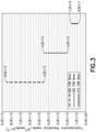
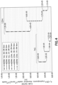
- FIGS. 3 and 4 graphs are providing illustrating the length-to-diameter ratio (i.e., the ratio of the theoretical hydrodynamic needle length to the fourth power of the inner diameter, L hydrodynamic theoretical needle / D needle_inner 4 ) and the flow factor K 1 , respectively, for various syringes that include a cannula having an 8mm exposed length, according to aspects of the disclosure.
- an acceptable range of the length-to-diameter ratio (L hydrodynamic theoretical needle / D needle_inner 4 ) is provided for each of a 27G, 29G and 30G cannula.
- the length-to-diameter ratio of the 27G cannula is between 8.5 ⁇ 10 11 m -3 and 1.5 ⁇ 10 12 m -3
- the length-to-diameter ratio of the 29G cannula is between 2 ⁇ 10 12 m -3 and 4. 5 ⁇ 10 12 m -3
- the length-to-diameter ratio of the 30G cannula is between 4.5 ⁇ 10 12 m -3 and 8.5 ⁇ 10 12 m -3 .
- An acceptable range of the length-to-diameter ratio across all of the or 27G, 29G and 30G cannulas is thus between 8.5 ⁇ 10 11 and 8.5 ⁇ 10 12 m -3 , according to aspects of the present disclosure.
- an acceptable range of a flow factor K 1 is provided for 1mLL syringes having a 27G, 29G or 30G cannula and for 2.25 mLL syringes having a 27G, 29G or 30G cannula.
- the flow factor K 1 of the 1mLL syringes is between 34,000m and 63,000m for the 27G cannula, 79,000m and 1.9 ⁇ 10 5 m for the 29G cannula, and 1.8 ⁇ 10 5 m and 3.6 ⁇ 10 5 m for the 30G cannula
- the flow factor K 1 of the 2.25mLL syringes is between 1.1 ⁇ 10 5 m and 2.2 ⁇ 10 5 m for the 27G cannula, 2.7 ⁇ 10 5 m and 6.6 ⁇ 10 5 m for the 29G cannula, 6.0 ⁇ 10 5 m and 1.3 ⁇ 10 6 m for the 30G cannula.
- An acceptable range of the flow factor K 1 across the 1mLL and 2.25mLL syringes and all of the 27G, 29G and 30G cannulas is thus between 34,000 and 1.3 ⁇ 10 6 meters.
Landscapes
- Health & Medical Sciences (AREA)
- Vascular Medicine (AREA)
- Engineering & Computer Science (AREA)
- Anesthesiology (AREA)
- Biomedical Technology (AREA)
- Heart & Thoracic Surgery (AREA)
- Hematology (AREA)
- Life Sciences & Earth Sciences (AREA)
- Animal Behavior & Ethology (AREA)
- General Health & Medical Sciences (AREA)
- Public Health (AREA)
- Veterinary Medicine (AREA)
- Infusion, Injection, And Reservoir Apparatuses (AREA)
Abstract

Description
- The present disclosure relates to cannulas for syringes and other medical devices.
- Cannulas are a ubiquitous component of modern medical care. Cannulas are used for example, to pierce a patient's skin to create a vascular access site for the administration of medicaments and other fluids (e.g. saline), or to withdraw blood from the patient. To reduce patient discomfort and the risk of injury, the outer diameter of cannulas is desirably minimized. However, the lumen of the cannula must be of sufficient diameter to allow the medicament or other fluid to flow through the cannula at an adequate rate, whatever the viscosity of the injected drug. As such, it is desirable to produce cannula with thin sidewalls to minimize the outer diameter while maximizing the inner diameter.
- Embodiments of the present disclosure are directed to a medical injection cannula configured for use with a syringe. The cannula includes a sidewall defining a lumen and having a proximal end and a distal end, and a beveled tip defining an opening to the lumen, wherein a length-to-diameter ratio of the cannula is defined by a ratio

- In accordance with an embodiment, the hydrodynamic length of the cannula Lhydrodynamic extends from a break of a transition region of the syringe to a proximal end of the opening of the beveled tip.
- In accordance with an embodiment, the outer diameter of the sidewall corresponds to a cannula standard for a 27G, 29G or 30G cannula.
- In accordance with an embodiment, the outer diameter of the sidewall is for the 27G cannula and the ratio

- In accordance with an embodiment, the outer diameter of the sidewall is for the 29G cannula and the ratio

- In accordance with an embodiment, the outer diameter of the sidewall is for the 30G cannula and the ratio

- In accordance with an embodiment, the outer diameter of the sidewall is substantially constant between the proximal end and the distal end.
- Also provided herein is a medical injection assembly including a syringe having a sidewall and a distal end, and a cannula connected to the distal end. The cannula further includes a sidewall defining a lumen and having a proximal end and a distal end and a beveled tip defining an opening to the lumen, wherein a flow factor K1 of a fluid through the lumen of the cannula is approximated by the equation

- In accordance with an embodiment, the inside volume of the syringe is comprised between 1 mL and 2.25 mL.
- In accordance with an embodiment, the sidewall has a transition region wherein the inner diameter transitions to a break at which an inner diameter of the sidewall is approximately equal to the inner diameter of the cannula.
- In accordance with an embodiment, the hydrodynamic length of the cannula extends from the break of the syringe to a proximal end of the opening of the beveled tip.
- In accordance with an embodiment, the outer diameter of the sidewall corresponds to a cannula standard for a 27G, 29G or 30G cannula.
- In accordance with an embodiment, the outer diameter of the sidewall of the cannula is substantially constant between the proximal end and the distal end.
- In accordance with an embodiment, the syringe further includes a stopper slidably disposed within the sidewall of the syringe.
- Further details and advantages of the various examples described in detail herein will become clear upon reviewing the following detailed description of the various examples in conjunction with the accompanying drawing figures.
- The above-mentioned and other features and advantages of this disclosure, and the manner of attaining them, will become more apparent and the disclosure itself will be better understood by reference to the following descriptions of embodiments of the disclosure taken in conjunction with the accompanying drawings, wherein:
-
FIG. 1 is a schematic of a cannula attached to a distal end of a syringe barrel. -
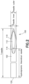
FIG. 2 is a top view of the cannula ofFIG. 1 . -
FIG. 3 is a graph illustrating acceptable length-to-diameter ratios of 27G, 29G and 30G cannulas of 8mm exposed length, according to aspects of the disclosure. -
FIG. 4 is a graph illustrating acceptable flow factors K1 of 1mLL and 2.25mLL syringes having a 27G, 29G or 30G cannula of 8mm exposed length, according to aspects of the disclosure. - Corresponding reference characters indicate corresponding parts throughout the several views. The exemplifications set out herein illustrate exemplary embodiments of the disclosure, and such exemplifications are not to be construed as limiting the scope of the disclosure in any manner.
- The following description is provided to enable those skilled in the art to make and use the described aspects contemplated for carrying out the disclosure. Various modifications, equivalents, variations, and alternatives, however, will remain readily apparent to those skilled in the art. Any and all such modifications, variations, equivalents, and alternatives are intended to fall within the spirit and scope of the present disclosure.
- For purposes of the description hereinafter, the terms "upper", "lower", "right", "left", "vertical", "horizontal", "top", "bottom", "lateral", "longitudinal", and derivatives thereof shall relate to the invention as it is oriented in the drawing figures. However, it is to be understood that the invention may assume various alternative variations, except where expressly specified to the contrary. It is also to be understood that the specific devices illustrated in the attached drawings, and described in the following specification, are simply exemplary aspects of the invention. Hence, specific dimensions and other physical characteristics related to the aspects disclosed herein are not to be considered as limiting.
- All numbers used in the specification and claims are to be understood as being modified in all instances by the term "about". The terms "approximately", "about", and "substantially" mean a range of plus or minus ten percent of the stated value. Further, the term "substantially equal" and like terms mean that the compared values or dimensions are within a range of plus or minus ten percent of one another.
- The terms "first", "second", and the like are not intended to refer to any particular order or chronology, but refer to different conditions, properties, or elements.
- As used herein with reference to an injection apparatus such as a syringe, the term "proximal" refers to an end of the apparatus farthest from the outlet, or to a direction toward the end of the apparatus farthest from the outlet. As used herein with reference to an injection apparatus such as a syringe, the term "distal" refers to an end of the device or apparatus closest to the outlet, or to a direction toward the end of the apparatus closest to the outlet.
- As used herein, "at least one of" is synonymous with "one or more of'. For example, the phrase "at least one of A, B, and C" means any one of A, B, or C, or any combination of any two or more of A, B, or C. For example, "at least one of A, B, and C" includes one or more of A alone; or one or more of B alone; or one or more of C alone; or one or more of A and one or more of B; or one or more of A and one or more of C; or one or more of B and one or more of C; or one or more of all of A, B, and C.
- Referring now to
FIGS. 1 and2 , acannula 100 in accordance with the present disclosure includes asidewall 102 extending between adistal end 110 and aproximal end 120. Thesidewall 102 has an outer diameter Dneedle_outer and an inner diameter Dneedle_inner, with a difference between the outer diameter Dneedle_outer and the inner diameter Dneedle_inner defining a wall thickness. The inner diameter Dneedle_inner of thesidewall 102 defines a lumen whose cross-section is substantially circular and through which a medicament, blood, or other fluid can flow. The outer diameter Dneedle_outer of thesidewall 102 may be equivalent to industry-standard nominal sizes for a selected cannula gauge (G), with the gauge size defining the limits for the outer diameter. As non-limiting examples, a 27G cannula will have an outer diameter of between 0.400 and 0.420 mm, a 29G cannula will have an outer diameter of between 0.324 and 0.351 mm, and a 30G cannula will have an outer diameter of between 0.298 and 0.320 mm. The outer diameter Dneedle_outer of thesidewall 102 may be substantially constant between theproximal end 120 and thedistal end 110. Thedistal end 110 may include a beveled tip configured for piercing a patient's skin to create a vascular access site. The beveled tip defines anopening 112 into the lumen. The opening has aproximal end 114. Theproximal end 120 of thecannula 100 is configured for connection to adistal end 204 of asyringe 200. The overall length Lneedle of thecannula 100 extends from the proximal-most end of thesidewall 102 to the distal-most end of thesidewall 102, including the length of the beveled tip of thedistal end 110. - As shown in
FIG. 1 , the syringe 200 (which may be formed of plastic or glass, typically glass) includes asidewall 202 having an inner diameter Dbarrel. The inner diameter Dbarrel depends on the volume of the barrel and the associated volume of drug to be injected. For instance, the barrel may be a 1mLL (1 mm long) or 2.25mLL (2.25 mm long) barrel, with the 1mLL barrel having an inner diameter Dbarrel of 6.35mm +/- 0.01mm and the 2.25mLL barrel having an inner diameter Dbarrel of 8.65mm +/- 0.2mm. Thesidewall 202 tapers toward thedistal end 204 of thesyringe 200 where thecannula 100 is connected (e.g., glued). In particular, thesidewall 202 tapers in atransition region 206 from the inner diameter Dbarrel to a smaller diameter slightly lower than the outer diameter Dneedle_outer of thecannula 100. Thetransition region 206 ends at abreak 208, at which point the inner diameter of thesidewall 202 is approximately equal to the inner diameter Dneedle_inner of thecannula 100. An elastomeric stopper 220 is slidably disposed within thesidewall 202 and can be advanced distally to expel fluid from thesyringe 200 through thecannula 100. The stopper 220 may be affixed to the end of a plunger (not shown) that can be depressed by a clinician's finger(s). - Three different lengths of the
cannula 100 are significant to measuring and characterizing the flow rate of a fluid through the lumen of thecannula 100. First, the aforementioned overall length Lneedle extends from the proximal-most end of thesidewall 102 to the distal-most end of thesidewall 102. Second, the theoretical hydrodynamic length Lhydrodynamic theoretical needle extends from the proximal-most end of thesidewall 102 to theproximal end 114 of theopening 112 of the beveled tip. Third, the actual hydrodynamic length Lhydrodynamic extends from thebreak 208 of the syringe 200 (where the diameter of the barrel is the smallest) to theproximal end 114 of theopening 112 of the beveled tip. - Injection force required to inject a fluid from the
syringe 200 through thecannula 100 is a complex calculation involving many factors. However, this calculation can be simplified for many relevant applications so long as stopper speed within the syringe is not abnormally high, and so long as dynamic viscosity of the fluid injected in not abnormally low. In particular, the calculation of an injection force F can be simplified as shown below in Equation 1:
syringe 200, and R is force due to friction of the stopper. - The terms in Equation 1 that are derived from the physical dimensions of the
cannula 100 andbarrel 200 can be gathered into a flow factor K1, as shown below in Equation 2:
- In other embodiments, where a theoretical hydrodynamic needle length Lhydrodynamic theoretical needle and inner diameter Dneedle_inner define the dimension of the
cannula 100, the flow factor K1, may be as shown below in Equation 3:
- In addition to the flow factor K1, the
cannula 100 according to the present disclosure can be characterized by what may generally be termed a "length-to-diameter ratio" of the cannula - with the length-to-diameter ratio defined herein as a ratio of the theoretical hydrodynamic needle length to the fourth power of the inner diameter (Lhydrodynamic theoretical needle / Dneedle_inner 4) or as a ratio of the actual hydrodynamic needle length to the fourth power of the hydrodynamic diameter (Lhydrodynamic / Dhydrodynamic 4). - The inner diameter Dneedle_inner of the
cannula 100 is typically ascertained from a dimensional drawing of thecannula 100, and, due to manufacturing limitations, is not necessarily reflective of a measurement from theactual cannula 100. In order to measure small diameter bores such as cannula lumens, gauge pins are typically used. However, gauge pins have their own limitations, notably in that gauge pins are incapable of reliably measuring a tapered bore and other inconsistencies in the bore introduced by manufacturing. Thus, instead of relying on physically measuring the inner diameter Dneedle_inner of thecannula 100, the hydrodynamic diameter Dhydrodynamic can be experimentally derived by pushing fluid through the cannula at a known or deduced flow rate. In some embodiments, the flow rate may be deduced by measuring the mass of fluid during a given time period and by knowing the density of the fluid. Based on this flow rate, the ratio of the actual hydrodynamic needle length to the fourth power of the hydrodynamic diameter (Lhydrodynamic/ Dhydrodynamic 4) can be deduced via the fluid viscosity and test pressure. If the actual hydrodynamic length Lhydrodynamic of the needle is known, the hydrodynamic diameter Dhydrodynamic may then be deduced. - Referring now to
FIGS. 3 and4 , graphs are providing illustrating the length-to-diameter ratio (i.e., the ratio of the theoretical hydrodynamic needle length to the fourth power of the inner diameter, Lhydrodynamic theoretical needle / Dneedle_inner 4) and the flow factor K1, respectively, for various syringes that include a cannula having an 8mm exposed length, according to aspects of the disclosure. - Referring first to
FIG. 3 , an acceptable range of the length-to-diameter ratio (Lhydrodynamic theoretical needle / Dneedle_inner 4) is provided for each of a 27G, 29G and 30G cannula. As shown therein, the length-to-diameter ratio of the 27G cannula is between 8.5×10¹¹ m-3 and 1.5×10¹² m-3, the length-to-diameter ratio of the 29G cannula is between 2×10¹² m-3 and 4. 5×10¹² m-3, and the length-to-diameter ratio of the 30G cannula is between 4.5×10¹² m-3 and 8.5×10¹²m-3. An acceptable range of the length-to-diameter ratio across all of the or 27G, 29G and 30G cannulas is thus between 8.5×10¹¹ and 8.5×10¹² m-3, according to aspects of the present disclosure. - Referring next to
FIG. 4 , an acceptable range of a flow factor K1 is provided for 1mLL syringes having a 27G, 29G or 30G cannula and for 2.25 mLL syringes having a 27G, 29G or 30G cannula. As shown therein, the flow factor K1 of the 1mLL syringes is between 34,000m and 63,000m for the 27G cannula, 79,000m and 1.9×10⁵m for the 29G cannula, and 1.8×10⁵m and 3.6×10⁵m for the 30G cannula, while the flow factor K1 of the 2.25mLL syringes is between 1.1×10⁵m and 2.2×10⁵m for the 27G cannula, 2.7×10⁵m and 6.6×10⁵m for the 29G cannula, 6.0×10⁵m and 1.3×10⁶m for the 30G cannula. An acceptable range of the flow factor K1 across the 1mLL and 2.25mLL syringes and all of the 27G, 29G and 30G cannulas is thus between 34,000 and 1.3×10⁶ meters. - Although the invention has been described in detail for the purpose of illustration based on what is currently considered to be the most practical and preferred embodiments, it is to be understood that such detail is solely for that purpose and that the invention is not limited to the disclosed embodiments, but, on the contrary, is intended to cover modifications and equivalent arrangements that are within the spirit and scope of the appended claims. For example, it is to be understood that the present invention contemplates that, to the extent possible, one or more features of any embodiment can be combined with one or more features of any other embodiment.
Claims (14)
- A medical injection cannula configured for use with a syringe, the cannula comprising:a sidewall defining a lumen and having a proximal end and a distal end; anda beveled tip defining an opening to the lumen,wherein a length-to-diameter ratio of the cannula is defined by a ratio:
 wherein Lhydrodynamic theoretical needle is a theoretical hydrodynamic length of the cannula, and Dneedle_inner is an inner diameter of the sidewall of the cannula; andwherein the length-to-diameter ratio is comprised between 8.5×10¹¹ and 8.5×10¹² m-3.
 - The medical injection cannula of claim 1, wherein the hydrodynamic length of the cannula Lhydrodynamic extends from a break of a transition region of the syringe to a proximal end of the opening of the beveled tip.
- The medical injection cannula of claim 1 or 2, wherein the outer diameter of the sidewall corresponds to a cannula standard for a 27G, 29G or 30G cannula.
- The medical injection cannula of claim 1 to 3, wherein the outer diameter of the sidewall is for the 27G cannula and the ratio

- The medical injection cannula of claim 1 to 3, wherein the outer diameter of the sidewall is for the 29G cannula and the ratio

- The medical injection cannula of claim 1 to 3, wherein the outer diameter of the sidewall is for the 30G cannula and the ratio

- The medical injection cannula of any of claims 1 to 6, wherein the outer diameter of the sidewall is substantially constant between the proximal end and the distal end.
- A medical injection assembly, comprising:a syringe having a sidewall and a distal end; anda cannula connected to the distal end, the cannula comprising:a sidewall defining a lumen and having a proximal end and a distal end; anda beveled tip defining an opening to the lumen,wherein a flow factor K1 of a fluid through the lumen of the cannula is approximated by the equation:
 wherein Dbarrel is an inner diameter of a sidewall of the syringe, Lhydrodynamic is a hydrodynamic length of the cannula, and Dhydrodynamic is an empirically derived inner diameter of the sidewall of the cannula; andwherein K1 is comprised between 34,000 and 1.3×10⁶ meters.
 - The assembly of claim 8 wherein the inside volume of the syringe is comprised between 1 mL and 2.25 mL.
- The assembly of claim 8 or 9, wherein the sidewall has a transition region wherein the inner diameter transitions to a break at which an inner diameter of the sidewall is approximately equal to the inner diameter of the cannula.
- The assembly of any of claims 8 to 10, wherein the hydrodynamic length of the cannula extends from the break of the syringe to a proximal end of the opening of the beveled tip.
- The assembly of any of claims 8 to 11, wherein the outer diameter of the sidewall corresponds to a cannula standard for a 27G, 29G or 30G cannula.
- The assembly of any of claims 8 to 12, wherein the outer diameter of the sidewall of the cannula is substantially constant between the proximal end and the distal end.
- The assembly of any of claims 8 to 13, further including a stopper slidably disposed within the sidewall of the syringe.
Priority Applications (7)
| Application Number | Priority Date | Filing Date | Title |
|---|---|---|---|
| EP23183866.5A EP4487890A1 (en) | 2023-07-06 | 2023-07-06 | Thin wall cannula |
| EP24743991.2A EP4739374A1 (en) | 2023-07-06 | 2024-06-28 | Thin wall cannula |
| PCT/US2024/035995 WO2025010191A1 (en) | 2023-07-06 | 2024-06-28 | Thin wall cannula |
| AU2024291169A AU2024291169A1 (en) | 2023-07-06 | 2024-06-28 | Thin wall cannula |
| CN202480045411.4A CN121511105A (en) | 2023-07-06 | 2024-06-28 | thin-walled cannula |
| KR1020267003807A KR20260035961A (en) | 2023-07-06 | 2024-06-28 | Thin wall cannula |
| MX2026000026A MX2026000026A (en) | 2023-07-06 | 2026-01-07 | Thin wall cannula |
Applications Claiming Priority (1)
| Application Number | Priority Date | Filing Date | Title |
|---|---|---|---|
| EP23183866.5A EP4487890A1 (en) | 2023-07-06 | 2023-07-06 | Thin wall cannula |
Publications (1)
| Publication Number | Publication Date |
|---|---|
| EP4487890A1 true EP4487890A1 (en) | 2025-01-08 |
Family
ID=87158507
Family Applications (1)
| Application Number | Title | Priority Date | Filing Date |
|---|---|---|---|
| EP23183866.5A Pending EP4487890A1 (en) | 2023-07-06 | 2023-07-06 | Thin wall cannula |
Country Status (1)
| Country | Link |
|---|---|
| EP (1) | EP4487890A1 (en) |
Citations (3)
| Publication number | Priority date | Publication date | Assignee | Title |
|---|---|---|---|---|
| US20020138050A1 (en) * | 1995-12-22 | 2002-09-26 | Jorgen K. Smedegaard | Injection needle |
| US20170216529A1 (en) * | 2014-08-06 | 2017-08-03 | Xeris Pharmaceuticals, Inc. | Syringes, kits, and methods for intracutaneous and/or subcutaneous injection of pastes |
| US20200268987A1 (en) * | 2019-02-26 | 2020-08-27 | Minhong Yu | Cannula Assembly for Higher Viscosity Injectable Drugs |
-
2023
- 2023-07-06 EP EP23183866.5A patent/EP4487890A1/en active Pending
Patent Citations (3)
| Publication number | Priority date | Publication date | Assignee | Title |
|---|---|---|---|---|
| US20020138050A1 (en) * | 1995-12-22 | 2002-09-26 | Jorgen K. Smedegaard | Injection needle |
| US20170216529A1 (en) * | 2014-08-06 | 2017-08-03 | Xeris Pharmaceuticals, Inc. | Syringes, kits, and methods for intracutaneous and/or subcutaneous injection of pastes |
| US20200268987A1 (en) * | 2019-02-26 | 2020-08-27 | Minhong Yu | Cannula Assembly for Higher Viscosity Injectable Drugs |
Similar Documents
| Publication | Publication Date | Title |
|---|---|---|
| KR102862025B1 (en) | Syringe-based delivery devices for vascular access devices | |
| US9393382B2 (en) | High-flow tapered peripheral IV catheter with side outlets | |
| JP3860835B2 (en) | A device that handles fluid by controlling pressure for medical purposes in particular | |
| RU2130324C1 (en) | Hypodermic needle | |
| CN202724337U (en) | Conduit with spiral slit | |
| US20050177117A1 (en) | Needle with lateral aperture | |
| JP2011520555A (en) | Conical expansion tip | |
| JP2023161010A (en) | syringe assembly | |
| US20120078095A1 (en) | High-flow tapered peripheral iv catheter with side outlets | |
| KR20140019786A (en) | Vascular needle system | |
| US5133362A (en) | Needle for use with vacuum test tube blood sampling systems | |
| CN111821560B (en) | Catheter insertion device and needle | |
| EP4596003A1 (en) | Thin wall cannula | |
| CN103446656A (en) | Anti-breaking nerve block indwelling catheter needle | |
| WO2004006996A1 (en) | Injection needle and liquid introducing instrument | |
| WO2025010191A1 (en) | Thin wall cannula | |
| EP2120742A1 (en) | The epidural needle and the epidural device | |
| US20240082509A1 (en) | Low dead space needle | |
| CN215653096U (en) | Non-destructive needle | |
| US10342957B2 (en) | Dual passageway safety syringe for injecting a medicament into non-venous tissue | |
| WO2023154911A1 (en) | Point of care collection and transfer device with luer lock access device and syringe compatibility | |
| CN115813761A (en) | Puncture-proof blunt needle of syringe for extracting liquid medicine and use method thereof | |
| US20230414868A1 (en) | Medical device | |
| EP3919100A1 (en) | Indwelling subcutaneous administration needle | |
| CN114901327A (en) | Syringe pump needle machine |
Legal Events
| Date | Code | Title | Description |
|---|---|---|---|
| PUAI | Public reference made under article 153(3) epc to a published international application that has entered the european phase |
Free format text: ORIGINAL CODE: 0009012 |
|
| STAA | Information on the status of an ep patent application or granted ep patent |
Free format text: STATUS: THE APPLICATION HAS BEEN PUBLISHED |
|
| AK | Designated contracting states |
Kind code of ref document: A1 Designated state(s): AL AT BE BG CH CY CZ DE DK EE ES FI FR GB GR HR HU IE IS IT LI LT LU LV MC ME MK MT NL NO PL PT RO RS SE SI SK SM TR |
|
| STAA | Information on the status of an ep patent application or granted ep patent |
Free format text: STATUS: REQUEST FOR EXAMINATION WAS MADE |
|
| 17P | Request for examination filed |
Effective date: 20250605 |
|
| STAA | Information on the status of an ep patent application or granted ep patent |
Free format text: STATUS: EXAMINATION IS IN PROGRESS |
|
| 17Q | First examination report despatched |
Effective date: 20260114 |