EP4487830A1 - Sealing member and blood bag set - Google Patents
Sealing member and blood bag set Download PDFInfo
- Publication number
- EP4487830A1 EP4487830A1 EP23766812.4A EP23766812A EP4487830A1 EP 4487830 A1 EP4487830 A1 EP 4487830A1 EP 23766812 A EP23766812 A EP 23766812A EP 4487830 A1 EP4487830 A1 EP 4487830A1
- Authority
- EP
- European Patent Office
- Prior art keywords
- sealing member
- base
- plug
- breakable portion
- distal end
- Prior art date
- Legal status (The legal status is an assumption and is not a legal conclusion. Google has not performed a legal analysis and makes no representation as to the accuracy of the status listed.)
- Granted
Links
Images




Classifications
-
- A—HUMAN NECESSITIES
- A61—MEDICAL OR VETERINARY SCIENCE; HYGIENE
- A61J—CONTAINERS SPECIALLY ADAPTED FOR MEDICAL OR PHARMACEUTICAL PURPOSES; DEVICES OR METHODS SPECIALLY ADAPTED FOR BRINGING PHARMACEUTICAL PRODUCTS INTO PARTICULAR PHYSICAL OR ADMINISTERING FORMS; DEVICES FOR ADMINISTERING FOOD OR MEDICINES ORALLY; BABY COMFORTERS; DEVICES FOR RECEIVING SPITTLE
- A61J1/00—Containers specially adapted for medical or pharmaceutical purposes
- A61J1/05—Containers specially adapted for medical or pharmaceutical purposes for collecting, storing or administering blood, plasma or medical fluids ; Infusion or perfusion containers
- A61J1/10—Bag-type containers
- A61J1/12—Bag-type containers with means for holding samples of contents
-
- A—HUMAN NECESSITIES
- A61—MEDICAL OR VETERINARY SCIENCE; HYGIENE
- A61J—CONTAINERS SPECIALLY ADAPTED FOR MEDICAL OR PHARMACEUTICAL PURPOSES; DEVICES OR METHODS SPECIALLY ADAPTED FOR BRINGING PHARMACEUTICAL PRODUCTS INTO PARTICULAR PHYSICAL OR ADMINISTERING FORMS; DEVICES FOR ADMINISTERING FOOD OR MEDICINES ORALLY; BABY COMFORTERS; DEVICES FOR RECEIVING SPITTLE
- A61J1/00—Containers specially adapted for medical or pharmaceutical purposes
- A61J1/05—Containers specially adapted for medical or pharmaceutical purposes for collecting, storing or administering blood, plasma or medical fluids ; Infusion or perfusion containers
- A61J1/10—Bag-type containers
-
- A—HUMAN NECESSITIES
- A61—MEDICAL OR VETERINARY SCIENCE; HYGIENE
- A61J—CONTAINERS SPECIALLY ADAPTED FOR MEDICAL OR PHARMACEUTICAL PURPOSES; DEVICES OR METHODS SPECIALLY ADAPTED FOR BRINGING PHARMACEUTICAL PRODUCTS INTO PARTICULAR PHYSICAL OR ADMINISTERING FORMS; DEVICES FOR ADMINISTERING FOOD OR MEDICINES ORALLY; BABY COMFORTERS; DEVICES FOR RECEIVING SPITTLE
- A61J1/00—Containers specially adapted for medical or pharmaceutical purposes
- A61J1/14—Details; Accessories therefor
-
- A—HUMAN NECESSITIES
- A61—MEDICAL OR VETERINARY SCIENCE; HYGIENE
- A61M—DEVICES FOR INTRODUCING MEDIA INTO, OR ONTO, THE BODY; DEVICES FOR TRANSDUCING BODY MEDIA OR FOR TAKING MEDIA FROM THE BODY; DEVICES FOR PRODUCING OR ENDING SLEEP OR STUPOR
- A61M39/00—Tubes, tube connectors, tube couplings, valves, access sites or the like, specially adapted for medical use
- A61M39/22—Valves or arrangement of valves
- A61M39/221—Frangible or pierceable closures within tubing
-
- A—HUMAN NECESSITIES
- A61—MEDICAL OR VETERINARY SCIENCE; HYGIENE
- A61M—DEVICES FOR INTRODUCING MEDIA INTO, OR ONTO, THE BODY; DEVICES FOR TRANSDUCING BODY MEDIA OR FOR TAKING MEDIA FROM THE BODY; DEVICES FOR PRODUCING OR ENDING SLEEP OR STUPOR
- A61M39/00—Tubes, tube connectors, tube couplings, valves, access sites or the like, specially adapted for medical use
- A61M39/22—Valves or arrangement of valves
- A61M39/221—Frangible or pierceable closures within tubing
- A61M2039/222—Frangible or pierceable closures within tubing frangible within tubing or bags
Definitions
- the present invention relates to a sealing member for sealing a flow path of a medical tube so as to allow the flow path of the medical tube to be in communication and a blood bag set.
- a sealing member is used to seal a medical tube to allow the medical tube to be in communication.
- the sealing member is a cap-shaped member fitted in the lumen of the medical tube, and seals the medical tube in the initial state.
- the sealing member includes a breakable portion. In response to bending the sealing member, the breakable portion is broken and the sealing member allows the medical tube to be in communication.
- Such a sealing member is used for, for example, a blood bag set ( JP 8-275986 A ).
- An object of the present invention is to solve the above drawbacks.
- a sealing member including: a base having an outer circumferential face for contact with an inner face of a medical tube, the base having a base flow path for allowing fluid to pass inside of the base, the base flow path extending in a direction of an axis of the sealing member, the base flow path being open at a proximal end of the base; a neck located at a distal end of the base such that the base has an outer diameter that reduces; a plug connected to the base through the neck, the plug extending from the base toward a side of location of a distal end of the sealing member in the direction of the axis of the sealing member, the plug occluding the base flow path; and a breakable portion including a thinnest portion of a boundary between a proximal end of the plug and the neck, in which, in viewing from the side of location of the distal end of the sealing member in the direction of the axis of the sealing member, the breakable portion is non-circular in
- a blood bag set including: the sealing member of the aspect described above; a blood bag that houses whole blood or a blood component; and a medical tube in communication with the blood bag, in which the sealing member occludes the medical tube in contact with an inner face of the medical tube so as to allow the medical tube to be in communication.
- the breakable portion is broken smoothly, thereby reducing occurrence of a poor communication. Further, according to the sealing member and the blood bag set, even in occurrence of a poor communication in the sealing member, hemolysis can be prevented because the breakable portion is large in flow-path cross-sectional area.
- a sealing member 10 is used for sealing a flow path 12a of a medical tube 12.
- the sealing member 10 is liquid-tightly secured to the flow path 12a of the medical tube 12 in the initial state.
- the sealing member 10 includes a base 14, a plug 16, and a breakable portion 18. In the initial state, the base 14 and the plug 16 are in connection through the breakable portion 18, and the plug 16 seals the flow path 12a. In response to bending the plug 16, the breakable portion 18 is broken, so that the sealing member 10 allows the flow path 12a to be in communication.
- Such a sealing member 10 is used for, for example, a blood bag set 20 illustrated in Fig. 9 .
- the blood bag set 20 includes a blood sampling needle 22, a first tube 24, a second tube 26, a third tube 28, a branch portion 30, an initial flow blood bag 32, a sampling holder 34, and a blood bag 36.
- the blood sampling needle 22 is connected to one end of the first tube 24.
- the other end of the first tube 24 is connected to a first port 30a of the branch portion 30 branched in three directions.
- the second tube 26 is connected to a second port 30b (see Fig. 9 ) of the branch portion 30, and the third tube 28 is connected to a third port 30c (see Fig. 9 ) of the branch portion 30.
- the second tube 26 connects the branch portion 30 and the initial flow blood bag 32.
- the sampling holder 34 is connected downstream of the initial flow blood bag 32.
- the third tube 28 connects the branch portion 30 and the blood bag 36 (blood sampling bag).
- the sealing member 10 of Fig. 1 is attached to the third tube 28 near the third port 30c of the branch portion 30. In the initial state, the sealing member 10 occludes the third port 30c and the third tube 28.
- the blood sampling needle 22 of the blood bag set 20 draws blood from a blood donor (donor). Because the third port 30c of the branch portion 30 is occluded by the sealing member 10, the drawn blood flows into the second tube 26 through the second port 30b. The blood is stored in the initial flow blood bag 32.
- the sampling holder 34 is used to collect a portion of the drawn blood in, for example, a sample tube.
- the operation of collecting the blood of the donor into the blood bag 36 is performed by occluding the second tube 26 of the blood bag set 20 with a clamp 31 and allowing the sealing member 10 to be in communication.
- the sealing member 10 is used, for example, for allowing a flow path of the blood bag set 20 to be in communication and occluding the flow path thereof.
- the sealing member 10 includes the base 14 and the plug 16.
- the base 14 has a cylindrical shape extending in the axial direction of the sealing member 10.
- An outer circumferential face 14a of the base 14 is secured to the flow path 12a in liquid-contact with an inner circumferential face 12b of the flow path 12a of the medical tube 12.
- the medical tube 12 is, for example, the third tube 28.
- the base 14 of the sealing member 10 has a base flow path 14b inside of the base 14.
- the base flow path 14b is surrounded by the inner circumferential face 14c of the base 14 concentric with the outer circumferential face 14a thereof.
- the base flow path 14b extends in the axial direction of the sealing member 10.
- the proximal end of the base flow path 14b is open at the proximal end of the base 14.
- the distal end of the base flow path 14b extends to the inside of the plug 16.
- the base 14 has a neck 38 at its distal end.
- the neck 38 is an extending portion that reduces in outer diameter to its distal end such that the outer diameter is smaller than that of the base 14.
- the neck 38 has an outer circumferential face 38a including a conical face.
- the plug 16 extends from the neck 38 toward its distal end in the axial direction of the sealing member 10.
- the plug 16 is integrally connected to the base 14 through the neck 38.
- the plug 16 has a solid portion.
- the solid portion of the plug 16 covers the side of location of the distal end of the base flow path 14b such that the plug 16 occludes the distal end of the base flow path 14b.
- the plug 16 has an outer diameter smaller than that of the base 14. Therefore, with the sealing member 10 secured to the medical tube 12, the plug 16 is separated from the inner circumferential face 12b of the medical tube 12.
- the plug 16 has three ridges 40a radially protruding outside from the central axis of the sealing member 10.
- the three ridges 40a of the plug 16 are each circumferentially disposed at an angle of 120° around the central axis.
- Each of the ridges 40a extends linearly in the axial direction of the sealing member 10.
- the breakable portion 18 includes each top 40 at the boundary between the corresponding ridge 40a and the neck 38.
- a relatively flat curved face 41a is located between one ridge 40a and another ridge 40a adjacent thereto.
- the curved face 41a is a portion having a relatively small curvature, and connects two adjacent tops 40 due to such a smooth curved face.
- the breakable portion 18 includes a connection 41 at the boundary between the curved face 41a and the neck 38.
- the curved face 41a of the plug 16 may have a recessed face portion 42a curved in a recessed shape toward the central axis of the sealing member 10.
- the recessed face portion 42a includes a curved face having a center of curvature located outside the plug 16.
- the breakable portion 18 includes each recess 42 at the boundary between the corresponding recessed face portion 42a and the neck 38.
- the connection 41 including the recess 42 is a portion where the breakable portion 18 is relatively easily broken by the force of bending the plug 16. In the present embodiment, such an easily breakable portion appears in three directions, and thus the user can break the breakable portion 18 without concern for the orientation of the plug 16.
- the breakable portion 18 is located at the boundary between the proximal end of the plug 16 and the neck 38.
- the breakable portion 18 includes a groove 44 along a line where an outer circumferential face 16a of the plug 16 and an outer circumferential face 38a of the neck 38 intersect mutually.
- the groove 44 is the thinnest portion 45 that is the thinnest portion of the sealing member 10.
- the groove 44 extends linearly and extends circumferentially along the outer circumferential face 38a of the neck 38. As illustrated in Figs.
- the groove 44 in viewing from the side of location of the distal end of the sealing member 10 in the axial direction of the sealing member 10, the groove 44 has a plurality of such tops 40 and such recesses 42 (connections 41) as described above that are located between the tops 40, and extends circumferentially in a wavy manner. As illustrated in Fig. 1 , the groove 44 is also serpentine in the axial direction of the sealing member 10 in side view. In such a manner, the groove 44 extends three-dimensionally without extending along one plane.
- the groove 44 of the breakable portion 18 is the thinnest of the other portions of the sealing member 10.
- the groove 44 is easily broken resulting from the communicating operation of bending the plug 16.
- the entire region of the groove 44 is broken and the plug 16 is separated from the base 14.
- the base 14 with the breakable portion 18 broken has a broken portion 46 illustrated in Fig. 4B .
- the groove 44 has the broken portion 46 circumferentially wavy in viewing from the side of location of the distal end of the sealing member 10 in the axial direction of the sealing member 10.
- the sealing member 10 of the present embodiment acts as follows.
- the plug 16 of the sealing member 10 is separated from the inner circumferential face 12b of the medical tube 12, the plug 16 can be bent.
- the breakable portion 18 is broken.
- the recessed face portion 42a between each ridge 40a of the plug 16 is recessed, and thus the plug 16 is a portion to which the user can easily input the operation force.
- a stress concentration portion 50 is generated at one end and the other end in the circumferential direction of the recess 42.
- Such stress concentration portions 50 as described above are each a start point of breakage of the breakable portion 18 resulting from input of a relatively weak bending force. Due to expansion of the breaking part of the breakable portion 18, the breakable portion 18 of the sealing member 10 is reliably broken even with input of a weak bending force. As a result, the sealing member 10 can inhibits the occurrence frequency of a poor communication.
- the sealing member 10 has a three-dimensionally wavy broken portion 46A.
- the gap between the neck 38 and the plug 16 along the broken portion 46A serves as a fluid flow path.
- the three-dimensionally wavy broken portion 46A can have a relatively large flow-path cross-sectional area. Therefore, even in occurrence of a poor communication, the sealing member 10 can prevent the red blood cells in the blood from damage, resulting in reduction of the risk of hemolysis.
- a sealing member 100 of a comparative example in Fig. 7 includes a breakable portion 118 including a circular groove 144.
- a flow path formed by a broken portion 46A in occurrence of a poor communication is narrower.
- the sealing member 100 of the comparative example has an opening area of 7.55 mm 2
- the sealing member 10 of the present embodiment can has an opening area of 14.83 mm 2 larger than the opening area of the sealing member 100.
- the cross-sectional area of the flow path formed due to occurrence of a poor communication increases in accordance with the length of the broken portion 46
- the cross-sectional area of the flow path formed due to occurrence of a poor communication increases in accordance with the length of the broken portion 46A.
- the broken portion 46 of the sealing member 10 of the present embodiment is longer than the broken portion 46A of the sealing member 100 of the comparative example. Therefore, even in occurrence of a poor communication, the sealing member 10 can has a larger flow-path cross-sectional area formed by the broken portion 46, resulting in reduction of the risk of hemolysis.
- a breakable portion 18A may include two tops 40 in viewing from the side of location of the distal end of a sealing member 10 in the axial direction of a sealing member 10.
- a breakable portion 18B may include four tops 40 in viewing from the side of location of the distal end of a sealing member 10 in the axial direction of a sealing member 10.
- the thinnest portion 45 including the groove 44 (see Fig. 3 ) having a V-shaped cross section on the outer circumference side of the sealing member 10; however, the present embodiment is not limited thereto.
- Modification 3 of the present embodiment another configuration example of the thinnest portion 45 will be described.
- a sealing member 10B of the present embodiment includes a thinnest portion 45A.
- the thinnest portion 45A includes an inner thin portion 48 that increases in diameter of a plug 16 from the inner circumference side, and a step 52 provided at the boundary between a neck 38 and the plug 16.
- the step 52 is located at the boundary between an outer circumferential face 38a of the neck 38 and an outer circumferential face 16a of the plug 16.
- the step 52 includes a step face 52a facing a direction perpendicular to the axial direction of the sealing member 10B.
- the step face 52a and the outer circumferential face 16a of the plug 16 intersect substantially perpendicularly with each other.
- the neck 38 reduces in thickness and the thinnest portion 45A is located.
- the thinnest portion 45A is located between the outer circumferential face 16a and the inner thin portion 48, and has a width in the axial direction of the sealing member 10B.
- the thinnest portion 45A extends over the entire region in the circumferential direction of the plug 16.
- a breakable portion 18B of the present modification is provided on a step 52 of the thinnest portion 45A.
- the breakable portion 18B extends over the entire region in the circumferential direction.
- stress concentrates on the step 52 of the thinnest portion 45A.
- the breakable portion 18B is broken.
- the breakable portion 18B of the thinnest portion 45A can be broken resulting from a bending operation on the plug 16.
- the sealing member 10 and the blood bag set 20 of the present embodiment are summarized as follows.
- a sealing member 10 including: a base 14 having an outer circumferential face 14a for contact with an inner face of a medical tube 12, the base 14 having a base flow path 14b for allowing fluid to pass inside of the base 14, the base flow path extending in a direction of an axis of the sealing member 10, the base flow path being open at a proximal end of the base 14; a neck 38 located at a distal end of the base 14 such that the base 14 has an outer diameter that reduces; a plug 16 connected to the base 14 through the neck 38, the plug 16 extending from the base 14 toward a side of location of a distal end of the sealing member 10 in the direction of the axis of the sealing member 10, the plug 16 occluding the base flow path; and a breakable portion 18 including a thinnest portion 45 of a boundary between a proximal end of the plug 16 and the neck 38, in which, in viewing from the side of location of the distal end of the sealing member 10 in the
- the sealing member described above has a stress concentration portion 50 on the breakable portion.
- the breakable portion can be broken reliably even with a weak force.
- the frequency of occurrence of a poor communication of the breakable portion is inhibited.
- the breakable portion has a large opening area of the gap formed by the breakable portion, even in occurrence of a poor communication with the breakable portion not partially broken. Therefore, the sealing member can reduce the risk of hemolysis.
- the breakable portion may include the thinnest portion extending in a circumferential direction over entire of the boundary between the proximal end of the plug and the neck along the boundary.
- the breakable portion can be broken with a force from any direction in the circumferential direction, and thus the sealing member is excellent in operability.
- each of the plurality of connections of the breakable portion may include a recess 42 recessed toward a center.
- a portion where the plug is easily bent is located in a relatively flat portion between two adjacent tops of the plurality of tops. Therefore, the breakable portion can be broken more reliably.
- the breakable portion may be wavy in shape in the circumferential direction due to the plurality of tops and the recess. Due to the wavy shape of the breakable portion, the opening area increases in occurrence of a poor communication.
- the plurality of tops of the breakable portion may be three in number.
- a portion where the plug is easily bent is located in a relatively flat portion between two adjacent tops of the plurality of tops.
- the relatively flat portion is large in width, the breakable portion can be easily broken even with a weak pressurizing force.
- the neck may have a conical face inclined such that the diameter of the neck gradually reduces toward the side of location of the distal end of the sealing member in the direction of the axis of the sealing member, and the breakable portion may be located on the conical face.
- a sealing member can include a breakable portion that is three-dimensionally wavy in shape at the boundary between the neck and the plug, and thus the opening area of the flow path can increase even in occurrence of a poor communication. Therefore, the sealing member can reduce the risk of hemolysis in occurrence of the poor communication.
- a blood bag set 20 including: the sealing member described above; a blood bag 36 that houses whole blood or a blood component; and a medical tube in communication with the blood bag 36, in which the sealing member occludes the medical tube in contact with an inner face of the medical tube so as to allow the medical tube to be in communication.
- the blood bag set can reduce the risk of hemolysis with the sealing member.
Landscapes
- Health & Medical Sciences (AREA)
- Life Sciences & Earth Sciences (AREA)
- Veterinary Medicine (AREA)
- Public Health (AREA)
- General Health & Medical Sciences (AREA)
- Animal Behavior & Ethology (AREA)
- Pharmacology & Pharmacy (AREA)
- Hematology (AREA)
- Heart & Thoracic Surgery (AREA)
- Biomedical Technology (AREA)
- Anesthesiology (AREA)
- Engineering & Computer Science (AREA)
- Pulmonology (AREA)
- Medical Preparation Storing Or Oral Administration Devices (AREA)
Abstract
Description
- The present invention relates to a sealing member for sealing a flow path of a medical tube so as to allow the flow path of the medical tube to be in communication and a blood bag set.
- A sealing member is used to seal a medical tube to allow the medical tube to be in communication. The sealing member is a cap-shaped member fitted in the lumen of the medical tube, and seals the medical tube in the initial state. The sealing member includes a breakable portion. In response to bending the sealing member, the breakable portion is broken and the sealing member allows the medical tube to be in communication.
- Such a sealing member is used for, for example, a blood bag set (
JP 8-275986 A - Insufficient bending of the sealing member at the communicating operation causes a poor communication in which part of the breakable portion remains connected. Even in such a poor communication, the sealing member can allow liquid such as blood to flow and pass. However, in the case of a traditional sealing member, in passing of blood through a narrow breakable portion due to a poor communication, red blood cells may be damaged to cause hemolysis.
- An object of the present invention is to solve the above drawbacks.
- According to one aspect of the disclosure below, provided is a sealing member including: a base having an outer circumferential face for contact with an inner face of a medical tube, the base having a base flow path for allowing fluid to pass inside of the base, the base flow path extending in a direction of an axis of the sealing member, the base flow path being open at a proximal end of the base; a neck located at a distal end of the base such that the base has an outer diameter that reduces; a plug connected to the base through the neck, the plug extending from the base toward a side of location of a distal end of the sealing member in the direction of the axis of the sealing member, the plug occluding the base flow path; and a breakable portion including a thinnest portion of a boundary between a proximal end of the plug and the neck, in which, in viewing from the side of location of the distal end of the sealing member in the direction of the axis of the sealing member, the breakable portion is non-circular in shape, the breakable portion including a plurality of tops and a plurality of connections between the plurality of tops, and a distance between the base and the axis is larger than a radius of a circle inscribed in the plurality of connections, and the base is located outside the plurality of connections in a radial direction of the sealing member.
- According to another aspect of the disclosure below, provided is a blood bag set including: the sealing member of the aspect described above; a blood bag that houses whole blood or a blood component; and a medical tube in communication with the blood bag, in which the sealing member occludes the medical tube in contact with an inner face of the medical tube so as to allow the medical tube to be in communication.
- According to the sealing member and the blood bag set of the aspects described above, the breakable portion is broken smoothly, thereby reducing occurrence of a poor communication. Further, according to the sealing member and the blood bag set, even in occurrence of a poor communication in the sealing member, hemolysis can be prevented because the breakable portion is large in flow-path cross-sectional area.
-
-
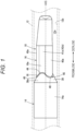
Fig. 1 is a side view of a sealing member according to an embodiment. -
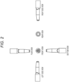
Fig. 2 is a six-sided view of the sealing member ofFig. 1 . -
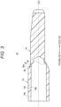
Fig. 3 is a longitudinal sectional view of the sealing member ofFig. 1 . -
Fig. 4A is a perspective view of the sealing member ofFig. 1 .Fig. 4B is a view of a broken portion after separation of a plug of the sealing member ofFig. 1 in viewing from the side of location of the distal end of the sealing member in the axial direction of the sealing member. -
Fig. 5 is an illustration of the distribution of stress generated in the breakable portion resulting from bending of the plug of the sealing member ofFig. 1 . -
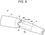
Fig. 6 is an explanatory view of the sealing member ofFig. 1 in occurrence of a poor communication. -
Fig. 7 is an explanatory view of a sealing member in occurrence of a poor communication according to a comparative example. -
Fig. 8 is a comparison table of the sealing member according to the comparative example and the sealing member ofFig. 1 in the cross-sectional shape and opening area of the breakable portion. -
Fig. 9 is a schematic view of a blood bag set including the sealing member ofFig. 1 . -
Fig. 10A is a view of the shape of a breakable portion according to Modification 1 of the embodiment.Fig. 10B is a view of the shape of a breakable portion according to Modification 2 of the embodiment. -
Fig. 11 is a sectional view of the shape of a breakable portion according to Modification 3 of the embodiment. - As illustrated in
Fig. 1 , asealing member 10 according to the present embodiment is used for sealing aflow path 12a of amedical tube 12. The sealingmember 10 is liquid-tightly secured to theflow path 12a of themedical tube 12 in the initial state. The sealingmember 10 includes abase 14, aplug 16, and abreakable portion 18. In the initial state, thebase 14 and theplug 16 are in connection through thebreakable portion 18, and theplug 16 seals theflow path 12a. In response to bending theplug 16, thebreakable portion 18 is broken, so that the sealingmember 10 allows theflow path 12a to be in communication. - Such a sealing
member 10 is used for, for example, a blood bag set 20 illustrated inFig. 9 . The blood bag set 20 includes ablood sampling needle 22, afirst tube 24, asecond tube 26, athird tube 28, abranch portion 30, an initialflow blood bag 32, asampling holder 34, and ablood bag 36. - The
blood sampling needle 22 is connected to one end of thefirst tube 24. The other end of thefirst tube 24 is connected to afirst port 30a of thebranch portion 30 branched in three directions. Thesecond tube 26 is connected to asecond port 30b (seeFig. 9 ) of thebranch portion 30, and thethird tube 28 is connected to athird port 30c (seeFig. 9 ) of thebranch portion 30. Thesecond tube 26 connects thebranch portion 30 and the initialflow blood bag 32. Thesampling holder 34 is connected downstream of the initialflow blood bag 32. Thethird tube 28 connects thebranch portion 30 and the blood bag 36 (blood sampling bag). The sealingmember 10 ofFig. 1 is attached to thethird tube 28 near thethird port 30c of thebranch portion 30. In the initial state, the sealingmember 10 occludes thethird port 30c and thethird tube 28. - The
blood sampling needle 22 of the blood bag set 20 draws blood from a blood donor (donor). Because thethird port 30c of thebranch portion 30 is occluded by the sealingmember 10, the drawn blood flows into thesecond tube 26 through thesecond port 30b. The blood is stored in the initialflow blood bag 32. Thesampling holder 34 is used to collect a portion of the drawn blood in, for example, a sample tube. - The operation of collecting the blood of the donor into the
blood bag 36 is performed by occluding thesecond tube 26 of the blood bag set 20 with aclamp 31 and allowing the sealingmember 10 to be in communication. In such a manner, the sealingmember 10 is used, for example, for allowing a flow path of the blood bag set 20 to be in communication and occluding the flow path thereof. - As illustrated in
Figs. 1 to 4A , the sealingmember 10 includes thebase 14 and theplug 16. Thebase 14 has a cylindrical shape extending in the axial direction of the sealingmember 10. An outercircumferential face 14a of thebase 14 is secured to theflow path 12a in liquid-contact with an innercircumferential face 12b of theflow path 12a of themedical tube 12. Themedical tube 12 is, for example, thethird tube 28. As illustrated inFig. 3 , thebase 14 of the sealingmember 10 has abase flow path 14b inside of thebase 14. Thebase flow path 14b is surrounded by the innercircumferential face 14c of thebase 14 concentric with the outercircumferential face 14a thereof. Thebase flow path 14b extends in the axial direction of the sealingmember 10. The proximal end of thebase flow path 14b is open at the proximal end of thebase 14. The distal end of thebase flow path 14b extends to the inside of theplug 16. - As illustrated in
Fig. 1 , thebase 14 has aneck 38 at its distal end. Theneck 38 is an extending portion that reduces in outer diameter to its distal end such that the outer diameter is smaller than that of thebase 14. Theneck 38 has an outercircumferential face 38a including a conical face. - The
plug 16 extends from theneck 38 toward its distal end in the axial direction of the sealingmember 10. In the initial state, theplug 16 is integrally connected to the base 14 through theneck 38. As illustrated inFig. 3 , theplug 16 has a solid portion. The solid portion of theplug 16 covers the side of location of the distal end of thebase flow path 14b such that theplug 16 occludes the distal end of thebase flow path 14b. As illustrated inFig. 1 , theplug 16 has an outer diameter smaller than that of thebase 14. Therefore, with the sealingmember 10 secured to themedical tube 12, theplug 16 is separated from the innercircumferential face 12b of themedical tube 12. - As illustrated in
Fig. 4A , theplug 16 has threeridges 40a radially protruding outside from the central axis of the sealingmember 10. The threeridges 40a of theplug 16 are each circumferentially disposed at an angle of 120° around the central axis. Each of theridges 40a extends linearly in the axial direction of the sealingmember 10. Thebreakable portion 18 includes each top 40 at the boundary between thecorresponding ridge 40a and theneck 38. A relatively flatcurved face 41a is located between oneridge 40a and anotherridge 40a adjacent thereto. Thecurved face 41a is a portion having a relatively small curvature, and connects twoadjacent tops 40 due to such a smooth curved face. Thebreakable portion 18 includes aconnection 41 at the boundary between thecurved face 41a and theneck 38. - As illustrated, the
curved face 41a of theplug 16 may have a recessedface portion 42a curved in a recessed shape toward the central axis of the sealingmember 10. The recessedface portion 42a includes a curved face having a center of curvature located outside theplug 16. Thebreakable portion 18 includes eachrecess 42 at the boundary between the corresponding recessedface portion 42a and theneck 38. Theconnection 41 including therecess 42 is a portion where thebreakable portion 18 is relatively easily broken by the force of bending theplug 16. In the present embodiment, such an easily breakable portion appears in three directions, and thus the user can break thebreakable portion 18 without concern for the orientation of theplug 16. - As illustrated in
Fig. 1 , thebreakable portion 18 is located at the boundary between the proximal end of theplug 16 and theneck 38. Thebreakable portion 18 includes agroove 44 along a line where an outercircumferential face 16a of theplug 16 and an outercircumferential face 38a of theneck 38 intersect mutually. In the present embodiment, thegroove 44 is thethinnest portion 45 that is the thinnest portion of the sealingmember 10. Thegroove 44 extends linearly and extends circumferentially along the outercircumferential face 38a of theneck 38. As illustrated inFigs. 4A and 4B , in viewing from the side of location of the distal end of the sealingmember 10 in the axial direction of the sealingmember 10, thegroove 44 has a plurality ofsuch tops 40 and such recesses 42 (connections 41) as described above that are located between the tops 40, and extends circumferentially in a wavy manner. As illustrated inFig. 1 , thegroove 44 is also serpentine in the axial direction of the sealingmember 10 in side view. In such a manner, thegroove 44 extends three-dimensionally without extending along one plane. - As illustrated in
Fig. 3 , thegroove 44 of thebreakable portion 18 is the thinnest of the other portions of the sealingmember 10. Thus, thegroove 44 is easily broken resulting from the communicating operation of bending theplug 16. In response to the communicating operation, the entire region of thegroove 44 is broken and theplug 16 is separated from thebase 14. The base 14 with thebreakable portion 18 broken has a brokenportion 46 illustrated inFig. 4B . As illustrated, thegroove 44 has the brokenportion 46 circumferentially wavy in viewing from the side of location of the distal end of the sealingmember 10 in the axial direction of the sealingmember 10. - The sealing
member 10 of the present embodiment acts as follows. - As illustrated in
Fig. 1 , because theplug 16 of the sealingmember 10 is separated from the innercircumferential face 12b of themedical tube 12, theplug 16 can be bent. In response to application of a force of bending theplug 16 to the base 14 from the outside of themedical tube 12, thebreakable portion 18 is broken. Although the usage is not limited, the recessedface portion 42a between eachridge 40a of theplug 16 is recessed, and thus theplug 16 is a portion to which the user can easily input the operation force. - As illustrated in
Fig. 5 , in response to input of a force from therecess 42 toward the central axis, astress concentration portion 50 is generated at one end and the other end in the circumferential direction of therecess 42. Suchstress concentration portions 50 as described above are each a start point of breakage of thebreakable portion 18 resulting from input of a relatively weak bending force. Due to expansion of the breaking part of thebreakable portion 18, thebreakable portion 18 of the sealingmember 10 is reliably broken even with input of a weak bending force. As a result, the sealingmember 10 can inhibits the occurrence frequency of a poor communication. - As illustrated in
Fig. 6 , even in a case where part of thebreakable portion 18 remains without being broken, the sealingmember 10 has a three-dimensionally wavybroken portion 46A. In such a sealingmember 10, the gap between theneck 38 and theplug 16 along thebroken portion 46A serves as a fluid flow path. The three-dimensionally wavybroken portion 46A can have a relatively large flow-path cross-sectional area. Therefore, even in occurrence of a poor communication, the sealingmember 10 can prevent the red blood cells in the blood from damage, resulting in reduction of the risk of hemolysis. - In comparison with the sealing
member 10, a sealingmember 100 of a comparative example inFig. 7 includes abreakable portion 118 including acircular groove 144. In the sealingmember 100 of the comparative example, a flow path formed by abroken portion 46A in occurrence of a poor communication is narrower. - As illustrated in
Fig. 8 , the sealingmember 100 of the comparative example has an opening area of 7.55 mm2, whereas the sealingmember 10 of the present embodiment can has an opening area of 14.83 mm2 larger than the opening area of the sealingmember 100. In the sealingmember 10, the cross-sectional area of the flow path formed due to occurrence of a poor communication increases in accordance with the length of thebroken portion 46, and in the sealingmember 100, the cross-sectional area of the flow path formed due to occurrence of a poor communication increases in accordance with the length of thebroken portion 46A. Thebroken portion 46 of the sealingmember 10 of the present embodiment is longer than thebroken portion 46A of the sealingmember 100 of the comparative example. Therefore, even in occurrence of a poor communication, the sealingmember 10 can has a larger flow-path cross-sectional area formed by thebroken portion 46, resulting in reduction of the risk of hemolysis. - In the embodiment described above, the example in which the
groove 44 of thebreakable portion 18 includes the three tops 40 has been described, but the present embodiment is not limited thereto. For example, as in Modification 1 illustrated inFig. 10A , abreakable portion 18A may include two tops 40 in viewing from the side of location of the distal end of a sealingmember 10 in the axial direction of a sealingmember 10. In addition, as in Modification 2 illustrated inFig. 10B , abreakable portion 18B may include four tops 40 in viewing from the side of location of the distal end of a sealingmember 10 in the axial direction of a sealingmember 10. - In the above description, described has been the
thinnest portion 45 including the groove 44 (seeFig. 3 ) having a V-shaped cross section on the outer circumference side of the sealingmember 10; however, the present embodiment is not limited thereto. In Modification 3 of the present embodiment, another configuration example of thethinnest portion 45 will be described. - As illustrated in
Fig. 11 , a sealingmember 10B of the present embodiment includes athinnest portion 45A. Thethinnest portion 45A includes an innerthin portion 48 that increases in diameter of aplug 16 from the inner circumference side, and astep 52 provided at the boundary between aneck 38 and theplug 16. Thestep 52 is located at the boundary between an outercircumferential face 38a of theneck 38 and an outercircumferential face 16a of theplug 16. Thestep 52 includes astep face 52a facing a direction perpendicular to the axial direction of the sealingmember 10B. Thestep face 52a and the outercircumferential face 16a of theplug 16 intersect substantially perpendicularly with each other. On thestep 52, theneck 38 reduces in thickness and thethinnest portion 45A is located. Thethinnest portion 45A is located between the outercircumferential face 16a and the innerthin portion 48, and has a width in the axial direction of the sealingmember 10B. Thethinnest portion 45A extends over the entire region in the circumferential direction of theplug 16. - A
breakable portion 18B of the present modification is provided on astep 52 of thethinnest portion 45A. Thebreakable portion 18B extends over the entire region in the circumferential direction. In response to application of a bending force to theplug 16, stress concentrates on thestep 52 of thethinnest portion 45A. As a result, thebreakable portion 18B is broken. In such a manner, in the sealingmember 10B of the present modification, thebreakable portion 18B of thethinnest portion 45A can be broken resulting from a bending operation on theplug 16. - The sealing
member 10 and the blood bag set 20 of the present embodiment are summarized as follows. - According to the embodiment described above, provided is a sealing member 10 including: a base 14 having an outer circumferential face 14a for contact with an inner face of a medical tube 12, the base 14 having a base flow path 14b for allowing fluid to pass inside of the base 14, the base flow path extending in a direction of an axis of the sealing member 10, the base flow path being open at a proximal end of the base 14; a neck 38 located at a distal end of the base 14 such that the base 14 has an outer diameter that reduces; a plug 16 connected to the base 14 through the neck 38, the plug 16 extending from the base 14 toward a side of location of a distal end of the sealing member 10 in the direction of the axis of the sealing member 10, the plug 16 occluding the base flow path; and a breakable portion 18 including a thinnest portion 45 of a boundary between a proximal end of the plug 16 and the neck 38, in which, in viewing from the side of location of the distal end of the sealing member 10 in the direction of the axis of the sealing member 10, the breakable portion 18 is non-circular in shape, the breakable portion 18 including a plurality of tops 40 and a plurality of connections 41 between the plurality of tops 40, a distance between the base 14 and the axis is larger than a radius of a circle inscribed in the plurality of connections 41, and the base 14 is located outside the plurality of connections 41 in a radial direction of the sealing member 10.
- In response to bending of the plug, the sealing member described above has a
stress concentration portion 50 on the breakable portion. Thus, the breakable portion can be broken reliably even with a weak force. As a result, the frequency of occurrence of a poor communication of the breakable portion is inhibited. Further, the breakable portion has a large opening area of the gap formed by the breakable portion, even in occurrence of a poor communication with the breakable portion not partially broken. Therefore, the sealing member can reduce the risk of hemolysis. - In the sealing member described above, the breakable portion may include the thinnest portion extending in a circumferential direction over entire of the boundary between the proximal end of the plug and the neck along the boundary. The breakable portion can be broken with a force from any direction in the circumferential direction, and thus the sealing member is excellent in operability.
- In viewing from the side of location of the distal end of the sealing member in the direction of the axis of the sealing member, each of the plurality of connections of the breakable portion may include a
recess 42 recessed toward a center. A portion where the plug is easily bent is located in a relatively flat portion between two adjacent tops of the plurality of tops. Therefore, the breakable portion can be broken more reliably. - In viewing from the side of location of the distal end of the sealing member in the direction of the axis of the sealing member, the breakable portion may be wavy in shape in the circumferential direction due to the plurality of tops and the recess. Due to the wavy shape of the breakable portion, the opening area increases in occurrence of a poor communication.
- In viewing from the side of location of the distal end of the sealing member in the direction of the axis of the sealing member, the plurality of tops of the breakable portion may be three in number. A portion where the plug is easily bent is located in a relatively flat portion between two adjacent tops of the plurality of tops. In this case, because the direction in which the plug is easily bent appears in three directions, the user can perform a bending operation without being conscious of the orientation of the plug. Further, because the relatively flat portion is large in width, the breakable portion can be easily broken even with a weak pressurizing force.
- In the sealing member described above, the neck may have a conical face inclined such that the diameter of the neck gradually reduces toward the side of location of the distal end of the sealing member in the direction of the axis of the sealing member, and the breakable portion may be located on the conical face. Such a sealing member can include a breakable portion that is three-dimensionally wavy in shape at the boundary between the neck and the plug, and thus the opening area of the flow path can increase even in occurrence of a poor communication. Therefore, the sealing member can reduce the risk of hemolysis in occurrence of the poor communication.
- According to the embodiment described above, provided is a blood bag set 20 including: the sealing member described above; a
blood bag 36 that houses whole blood or a blood component; and a medical tube in communication with theblood bag 36, in which the sealing member occludes the medical tube in contact with an inner face of the medical tube so as to allow the medical tube to be in communication. - The blood bag set can reduce the risk of hemolysis with the sealing member.
- Note that the present invention is not limited to the embodiments described above, and thus various configurations may be adopted without departing from the gist of the present invention.
Claims (7)
- A sealing member comprising:a base having an outer circumferential face for contact with an inner face of a medical tube, the base having a base flow path for allowing fluid to pass inside of the base, the base flow path extending in a direction of an axis of the sealing member, the base flow path being open at a proximal end of the base;a neck located at a distal end of the base such that the base has an outer diameter that reduces;a plug connected to the base through the neck, the plug extending from the base toward a side of location of a distal end of the sealing member in the direction of the axis of the sealing member, the plug occluding the base flow path; anda breakable portion including a thinnest portion of a boundary between a proximal end of the plug and the neck, whereinin viewing from the side of location of the distal end of the sealing member in the direction of the axis of the sealing member, the breakable portion is non-circular in shape, the breakable portion including a plurality of tops and a plurality of connections between the plurality of tops, anda distance between the base and the axis is larger than a radius of a circle inscribed in the plurality of connections, and the base is located outside the plurality of connections in a radial direction of the sealing member.
- The sealing member according to claim 1, wherein the breakable portion includes the thinnest portion extending in a circumferential direction over an entire of the boundary between the proximal end of the plug and the neck along the boundary.
- The sealing member according to claim 2, wherein, in viewing from the side of location of the distal end of the sealing member in the direction of the axis of the sealing member, each of the plurality of connections of the breakable portion includes a recess recessed toward a center.
- The sealing member according to claim 3, wherein, in viewing from the side of location of the distal end of the sealing member in the direction of the axis of the sealing member, the breakable portion is wavy in shape in the circumferential direction due to the plurality of tops and the recess.
- The sealing member according to any one of claims 2 to 4, wherein, in viewing from the side of location of the distal end of the sealing member in the direction of the axis of the sealing member, the plurality of tops of the breakable portion is three in number.
- The sealing member according to any one of claims 1 to 5, wherein the neck has a conical face inclined such that a diameter of the neck gradually reduces toward the side of location of the distal end of the sealing member in the direction of the axis of the sealing member, and the breakable portion is located on the conical face.
- A blood bag set comprising:the sealing member according to any one of claims 1 to 6;a blood bag that houses whole blood or a blood component; anda medical tube in communication with the blood bag, whereinthe sealing member occludes the medical tube in contact with an inner face of the medical tube so as to allow the medical tube to be in communication.
Applications Claiming Priority (2)
| Application Number | Priority Date | Filing Date | Title |
|---|---|---|---|
| JP2022034092 | 2022-03-07 | ||
| PCT/JP2023/008443 WO2023171636A1 (en) | 2022-03-07 | 2023-03-07 | Sealing member and blood bag set |
Publications (3)
| Publication Number | Publication Date |
|---|---|
| EP4487830A1 true EP4487830A1 (en) | 2025-01-08 |
| EP4487830A4 EP4487830A4 (en) | 2025-07-02 |
| EP4487830B1 EP4487830B1 (en) | 2025-11-05 |
Family
ID=87935042
Family Applications (1)
| Application Number | Title | Priority Date | Filing Date |
|---|---|---|---|
| EP23766812.4A Active EP4487830B1 (en) | 2022-03-07 | 2023-03-07 | Sealing member and blood bag set |
Country Status (5)
| Country | Link |
|---|---|
| US (1) | US20240390228A1 (en) |
| EP (1) | EP4487830B1 (en) |
| JP (1) | JPWO2023171636A1 (en) |
| CN (1) | CN118891027A (en) |
| WO (1) | WO2023171636A1 (en) |
Family Cites Families (6)
| Publication number | Priority date | Publication date | Assignee | Title |
|---|---|---|---|---|
| JPH0717312Y2 (en) * | 1990-06-29 | 1995-04-26 | 川澄化学工業株式会社 | Communication member for medical equipment |
| JPH08275987A (en) * | 1995-04-03 | 1996-10-22 | Toyo Seikan Kaisha Ltd | Nozzle assembly for infusion bag, infusion bag, and method for manufacturing infusion bag |
| JP3429900B2 (en) | 1995-04-07 | 2003-07-28 | 川澄化学工業株式会社 | Communication piece of medical bag |
| US6132413A (en) * | 1998-03-06 | 2000-10-17 | Baxter International Inc. | Breakable cannula assemblies and methods for manipulating them |
| US20150238746A1 (en) * | 2014-02-26 | 2015-08-27 | Baxter Healthcare Sa | Frangible connector closure for tubular connector |
| EP3484574A1 (en) * | 2016-10-12 | 2019-05-22 | Fresenius Medical Care Holdings, Inc. | Medical fluid line connector |
-
2023
- 2023-03-07 JP JP2024506326A patent/JPWO2023171636A1/ja active Pending
- 2023-03-07 EP EP23766812.4A patent/EP4487830B1/en active Active
- 2023-03-07 WO PCT/JP2023/008443 patent/WO2023171636A1/en not_active Ceased
- 2023-03-07 CN CN202380025180.6A patent/CN118891027A/en active Pending
-
2024
- 2024-08-05 US US18/794,905 patent/US20240390228A1/en active Pending
Also Published As
| Publication number | Publication date |
|---|---|
| CN118891027A (en) | 2024-11-01 |
| JPWO2023171636A1 (en) | 2023-09-14 |
| EP4487830A4 (en) | 2025-07-02 |
| WO2023171636A1 (en) | 2023-09-14 |
| EP4487830B1 (en) | 2025-11-05 |
| US20240390228A1 (en) | 2024-11-28 |
Similar Documents
| Publication | Publication Date | Title |
|---|---|---|
| US11684757B2 (en) | Valved catheter assemblies and related methods | |
| CN104136068B (en) | Needleless connector | |
| US5199948A (en) | Needleless valve | |
| CN113521492B (en) | A sealing structure, delivery sheath and delivery system | |
| JP4429911B2 (en) | Medical fluid connector and use thereof | |
| US7241285B1 (en) | Medical site connection | |
| EP3641847B1 (en) | Closed stopcock | |
| US20040068238A1 (en) | Injection site for male luer or other tubular connector | |
| CN113855919A (en) | Catheter assembly | |
| EP4487830B1 (en) | Sealing member and blood bag set | |
| KR20240090478A (en) | Low profile access sheath | |
| JP7587536B2 (en) | Peripheral venous syringe capable of collecting blood, catheter assembly and related method | |
| JP2024504631A (en) | Blood collection assembly and related devices and methods | |
| EP2666511A1 (en) | Female-side connector | |
| US20240268798A1 (en) | Needle attachment for a spinal needle | |
| EP4169551B1 (en) | Outer needle assembly | |
| JP7563024B2 (en) | Vacuum Tube Holder | |
| CN219354043U (en) | Hemostatic valve and delivery sheath | |
| CN116407172B (en) | A sealing system and delivery sheath | |
| CN224039778U (en) | Unidirectional airtight joint and straight-through thereof | |
| AU2022204874B2 (en) | Valved catheter assemblies and related methods | |
| JP7756781B2 (en) | Optimized port stem geometry | |
| WO2025024083A1 (en) | Hemoshield device and related systems and methods | |
| US20230277832A1 (en) | Peelable Cathlock | |
| JPWO2023171636A5 (en) |
Legal Events
| Date | Code | Title | Description |
|---|---|---|---|
| STAA | Information on the status of an ep patent application or granted ep patent |
Free format text: STATUS: THE INTERNATIONAL PUBLICATION HAS BEEN MADE |
|
| PUAI | Public reference made under article 153(3) epc to a published international application that has entered the european phase |
Free format text: ORIGINAL CODE: 0009012 |
|
| STAA | Information on the status of an ep patent application or granted ep patent |
Free format text: STATUS: REQUEST FOR EXAMINATION WAS MADE |
|
| 17P | Request for examination filed |
Effective date: 20240930 |
|
| AK | Designated contracting states |
Kind code of ref document: A1 Designated state(s): AL AT BE BG CH CY CZ DE DK EE ES FI FR GB GR HR HU IE IS IT LI LT LU LV MC ME MK MT NL NO PL PT RO RS SE SI SK SM TR |
|
| DAV | Request for validation of the european patent (deleted) | ||
| DAX | Request for extension of the european patent (deleted) | ||
| A4 | Supplementary search report drawn up and despatched |
Effective date: 20250530 |
|
| RIC1 | Information provided on ipc code assigned before grant |
Ipc: A61J 1/12 20060101ALN20250523BHEP Ipc: A61M 39/22 20060101ALN20250523BHEP Ipc: A61M 39/20 20060101ALI20250523BHEP Ipc: A61J 1/10 20060101ALI20250523BHEP Ipc: A61J 1/14 20230101AFI20250523BHEP |
|
| GRAP | Despatch of communication of intention to grant a patent |
Free format text: ORIGINAL CODE: EPIDOSNIGR1 |
|
| STAA | Information on the status of an ep patent application or granted ep patent |
Free format text: STATUS: GRANT OF PATENT IS INTENDED |
|
| RIC1 | Information provided on ipc code assigned before grant |
Ipc: A61J 1/14 20230101AFI20250704BHEP Ipc: A61J 1/10 20060101ALI20250704BHEP Ipc: A61M 39/20 20060101ALI20250704BHEP Ipc: A61M 39/22 20060101ALN20250704BHEP Ipc: A61J 1/12 20060101ALN20250704BHEP |
|
| INTG | Intention to grant announced |
Effective date: 20250718 |
|
| GRAS | Grant fee paid |
Free format text: ORIGINAL CODE: EPIDOSNIGR3 |
|
| GRAA | (expected) grant |
Free format text: ORIGINAL CODE: 0009210 |
|
| STAA | Information on the status of an ep patent application or granted ep patent |
Free format text: STATUS: THE PATENT HAS BEEN GRANTED |
|
| AK | Designated contracting states |
Kind code of ref document: B1 Designated state(s): AL AT BE BG CH CY CZ DE DK EE ES FI FR GB GR HR HU IE IS IT LI LT LU LV MC ME MK MT NL NO PL PT RO RS SE SI SK SM TR |
|
| REG | Reference to a national code |
Ref country code: CH Ref legal event code: F10 Free format text: ST27 STATUS EVENT CODE: U-0-0-F10-F00 (AS PROVIDED BY THE NATIONAL OFFICE) Effective date: 20251105 Ref country code: GB Ref legal event code: FG4D |
|
| REG | Reference to a national code |
Ref country code: DE Ref legal event code: R096 Ref document number: 602023008385 Country of ref document: DE |
|
| REG | Reference to a national code |
Ref country code: IE Ref legal event code: FG4D |
|
| REG | Reference to a national code |
Ref country code: NL Ref legal event code: MP Effective date: 20251105 |
|
| PG25 | Lapsed in a contracting state [announced via postgrant information from national office to epo] |
Ref country code: ES Free format text: LAPSE BECAUSE OF FAILURE TO SUBMIT A TRANSLATION OF THE DESCRIPTION OR TO PAY THE FEE WITHIN THE PRESCRIBED TIME-LIMIT Effective date: 20251105 |
|
| REG | Reference to a national code |
Ref country code: LT Ref legal event code: MG9D |
|
| PG25 | Lapsed in a contracting state [announced via postgrant information from national office to epo] |
Ref country code: NO Free format text: LAPSE BECAUSE OF FAILURE TO SUBMIT A TRANSLATION OF THE DESCRIPTION OR TO PAY THE FEE WITHIN THE PRESCRIBED TIME-LIMIT Effective date: 20260205 |
|
| PGFP | Annual fee paid to national office [announced via postgrant information from national office to epo] |
Ref country code: DE Payment date: 20260128 Year of fee payment: 4 |
|
| PG25 | Lapsed in a contracting state [announced via postgrant information from national office to epo] |
Ref country code: FI Free format text: LAPSE BECAUSE OF FAILURE TO SUBMIT A TRANSLATION OF THE DESCRIPTION OR TO PAY THE FEE WITHIN THE PRESCRIBED TIME-LIMIT Effective date: 20251105 Ref country code: AT Free format text: LAPSE BECAUSE OF FAILURE TO SUBMIT A TRANSLATION OF THE DESCRIPTION OR TO PAY THE FEE WITHIN THE PRESCRIBED TIME-LIMIT Effective date: 20251105 Ref country code: HR Free format text: LAPSE BECAUSE OF FAILURE TO SUBMIT A TRANSLATION OF THE DESCRIPTION OR TO PAY THE FEE WITHIN THE PRESCRIBED TIME-LIMIT Effective date: 20251105 |
|
| PGFP | Annual fee paid to national office [announced via postgrant information from national office to epo] |
Ref country code: AT Payment date: 20260301 Year of fee payment: 4 |
|
| REG | Reference to a national code |
Ref country code: AT Ref legal event code: MK05 Ref document number: 1853537 Country of ref document: AT Kind code of ref document: T Effective date: 20251105 |
|
| PG25 | Lapsed in a contracting state [announced via postgrant information from national office to epo] |
Ref country code: NL Free format text: LAPSE BECAUSE OF FAILURE TO SUBMIT A TRANSLATION OF THE DESCRIPTION OR TO PAY THE FEE WITHIN THE PRESCRIBED TIME-LIMIT Effective date: 20251105 |
|
| PG25 | Lapsed in a contracting state [announced via postgrant information from national office to epo] |
Ref country code: RS Free format text: LAPSE BECAUSE OF FAILURE TO SUBMIT A TRANSLATION OF THE DESCRIPTION OR TO PAY THE FEE WITHIN THE PRESCRIBED TIME-LIMIT Effective date: 20260205 |
|
| PG25 | Lapsed in a contracting state [announced via postgrant information from national office to epo] |
Ref country code: IS Free format text: LAPSE BECAUSE OF FAILURE TO SUBMIT A TRANSLATION OF THE DESCRIPTION OR TO PAY THE FEE WITHIN THE PRESCRIBED TIME-LIMIT Effective date: 20260305 |
|
| PG25 | Lapsed in a contracting state [announced via postgrant information from national office to epo] |
Ref country code: PT Free format text: LAPSE BECAUSE OF FAILURE TO SUBMIT A TRANSLATION OF THE DESCRIPTION OR TO PAY THE FEE WITHIN THE PRESCRIBED TIME-LIMIT Effective date: 20260305 |
|
| PG25 | Lapsed in a contracting state [announced via postgrant information from national office to epo] |
Ref country code: PL Free format text: LAPSE BECAUSE OF FAILURE TO SUBMIT A TRANSLATION OF THE DESCRIPTION OR TO PAY THE FEE WITHIN THE PRESCRIBED TIME-LIMIT Effective date: 20251105 |
|
| PG25 | Lapsed in a contracting state [announced via postgrant information from national office to epo] |
Ref country code: LV Free format text: LAPSE BECAUSE OF FAILURE TO SUBMIT A TRANSLATION OF THE DESCRIPTION OR TO PAY THE FEE WITHIN THE PRESCRIBED TIME-LIMIT Effective date: 20251105 |
|
| PG25 | Lapsed in a contracting state [announced via postgrant information from national office to epo] |
Ref country code: BG Free format text: LAPSE BECAUSE OF FAILURE TO SUBMIT A TRANSLATION OF THE DESCRIPTION OR TO PAY THE FEE WITHIN THE PRESCRIBED TIME-LIMIT Effective date: 20251105 |
|
| PG25 | Lapsed in a contracting state [announced via postgrant information from national office to epo] |
Ref country code: LT Free format text: LAPSE BECAUSE OF FAILURE TO SUBMIT A TRANSLATION OF THE DESCRIPTION OR TO PAY THE FEE WITHIN THE PRESCRIBED TIME-LIMIT Effective date: 20251105 |
|
| PG25 | Lapsed in a contracting state [announced via postgrant information from national office to epo] |
Ref country code: SM Free format text: LAPSE BECAUSE OF FAILURE TO SUBMIT A TRANSLATION OF THE DESCRIPTION OR TO PAY THE FEE WITHIN THE PRESCRIBED TIME-LIMIT Effective date: 20251105 |
|
| PG25 | Lapsed in a contracting state [announced via postgrant information from national office to epo] |
Ref country code: DK Free format text: LAPSE BECAUSE OF FAILURE TO SUBMIT A TRANSLATION OF THE DESCRIPTION OR TO PAY THE FEE WITHIN THE PRESCRIBED TIME-LIMIT Effective date: 20251105 |
|
| PG25 | Lapsed in a contracting state [announced via postgrant information from national office to epo] |
Ref country code: IT Free format text: LAPSE BECAUSE OF FAILURE TO SUBMIT A TRANSLATION OF THE DESCRIPTION OR TO PAY THE FEE WITHIN THE PRESCRIBED TIME-LIMIT Effective date: 20251105 |
|
| PG25 | Lapsed in a contracting state [announced via postgrant information from national office to epo] |
Ref country code: EE Free format text: LAPSE BECAUSE OF FAILURE TO SUBMIT A TRANSLATION OF THE DESCRIPTION OR TO PAY THE FEE WITHIN THE PRESCRIBED TIME-LIMIT Effective date: 20251105 |
|
| PG25 | Lapsed in a contracting state [announced via postgrant information from national office to epo] |
Ref country code: CZ Free format text: LAPSE BECAUSE OF FAILURE TO SUBMIT A TRANSLATION OF THE DESCRIPTION OR TO PAY THE FEE WITHIN THE PRESCRIBED TIME-LIMIT Effective date: 20251105 |
|
| PG25 | Lapsed in a contracting state [announced via postgrant information from national office to epo] |
Ref country code: SK Free format text: LAPSE BECAUSE OF FAILURE TO SUBMIT A TRANSLATION OF THE DESCRIPTION OR TO PAY THE FEE WITHIN THE PRESCRIBED TIME-LIMIT Effective date: 20251105 |
|
| PG25 | Lapsed in a contracting state [announced via postgrant information from national office to epo] |
Ref country code: SE Free format text: LAPSE BECAUSE OF FAILURE TO SUBMIT A TRANSLATION OF THE DESCRIPTION OR TO PAY THE FEE WITHIN THE PRESCRIBED TIME-LIMIT Effective date: 20251105 |