EP4487825A1 - Low profile delivery system with lock wire lumen - Google Patents
Low profile delivery system with lock wire lumen Download PDFInfo
- Publication number
- EP4487825A1 EP4487825A1 EP24197747.9A EP24197747A EP4487825A1 EP 4487825 A1 EP4487825 A1 EP 4487825A1 EP 24197747 A EP24197747 A EP 24197747A EP 4487825 A1 EP4487825 A1 EP 4487825A1
- Authority
- EP
- European Patent Office
- Prior art keywords
- medical device
- catheter shaft
- flexible loop
- loop
- flexible
- Prior art date
- Legal status (The legal status is an assumption and is not a legal conclusion. Google has not performed a legal analysis and makes no representation as to the accuracy of the status listed.)
- Pending
Links
Images





Classifications
-
- A—HUMAN NECESSITIES
- A61—MEDICAL OR VETERINARY SCIENCE; HYGIENE
- A61F—FILTERS IMPLANTABLE INTO BLOOD VESSELS; PROSTHESES; DEVICES PROVIDING PATENCY TO, OR PREVENTING COLLAPSING OF, TUBULAR STRUCTURES OF THE BODY, e.g. STENTS; ORTHOPAEDIC, NURSING OR CONTRACEPTIVE DEVICES; FOMENTATION; TREATMENT OR PROTECTION OF EYES OR EARS; BANDAGES, DRESSINGS OR ABSORBENT PADS; FIRST-AID KITS
- A61F2/00—Filters implantable into blood vessels; Prostheses, i.e. artificial substitutes or replacements for parts of the body; Appliances for connecting them with the body; Devices providing patency to, or preventing collapsing of, tubular structures of the body, e.g. stents
- A61F2/95—Instruments specially adapted for placement or removal of stents or stent-grafts
-
- A—HUMAN NECESSITIES
- A61—MEDICAL OR VETERINARY SCIENCE; HYGIENE
- A61F—FILTERS IMPLANTABLE INTO BLOOD VESSELS; PROSTHESES; DEVICES PROVIDING PATENCY TO, OR PREVENTING COLLAPSING OF, TUBULAR STRUCTURES OF THE BODY, e.g. STENTS; ORTHOPAEDIC, NURSING OR CONTRACEPTIVE DEVICES; FOMENTATION; TREATMENT OR PROTECTION OF EYES OR EARS; BANDAGES, DRESSINGS OR ABSORBENT PADS; FIRST-AID KITS
- A61F2/00—Filters implantable into blood vessels; Prostheses, i.e. artificial substitutes or replacements for parts of the body; Appliances for connecting them with the body; Devices providing patency to, or preventing collapsing of, tubular structures of the body, e.g. stents
- A61F2/95—Instruments specially adapted for placement or removal of stents or stent-grafts
- A61F2/962—Instruments specially adapted for placement or removal of stents or stent-grafts having an outer sleeve
- A61F2/966—Instruments specially adapted for placement or removal of stents or stent-grafts having an outer sleeve with relative longitudinal movement between outer sleeve and prosthesis, e.g. using a push rod
-
- A—HUMAN NECESSITIES
- A61—MEDICAL OR VETERINARY SCIENCE; HYGIENE
- A61F—FILTERS IMPLANTABLE INTO BLOOD VESSELS; PROSTHESES; DEVICES PROVIDING PATENCY TO, OR PREVENTING COLLAPSING OF, TUBULAR STRUCTURES OF THE BODY, e.g. STENTS; ORTHOPAEDIC, NURSING OR CONTRACEPTIVE DEVICES; FOMENTATION; TREATMENT OR PROTECTION OF EYES OR EARS; BANDAGES, DRESSINGS OR ABSORBENT PADS; FIRST-AID KITS
- A61F2/00—Filters implantable into blood vessels; Prostheses, i.e. artificial substitutes or replacements for parts of the body; Appliances for connecting them with the body; Devices providing patency to, or preventing collapsing of, tubular structures of the body, e.g. stents
- A61F2/95—Instruments specially adapted for placement or removal of stents or stent-grafts
- A61F2002/9505—Instruments specially adapted for placement or removal of stents or stent-grafts having retaining means other than an outer sleeve, e.g. male-female connector between stent and instrument
-
- A—HUMAN NECESSITIES
- A61—MEDICAL OR VETERINARY SCIENCE; HYGIENE
- A61F—FILTERS IMPLANTABLE INTO BLOOD VESSELS; PROSTHESES; DEVICES PROVIDING PATENCY TO, OR PREVENTING COLLAPSING OF, TUBULAR STRUCTURES OF THE BODY, e.g. STENTS; ORTHOPAEDIC, NURSING OR CONTRACEPTIVE DEVICES; FOMENTATION; TREATMENT OR PROTECTION OF EYES OR EARS; BANDAGES, DRESSINGS OR ABSORBENT PADS; FIRST-AID KITS
- A61F2/00—Filters implantable into blood vessels; Prostheses, i.e. artificial substitutes or replacements for parts of the body; Appliances for connecting them with the body; Devices providing patency to, or preventing collapsing of, tubular structures of the body, e.g. stents
- A61F2/95—Instruments specially adapted for placement or removal of stents or stent-grafts
- A61F2002/9505—Instruments specially adapted for placement or removal of stents or stent-grafts having retaining means other than an outer sleeve, e.g. male-female connector between stent and instrument
- A61F2002/9511—Instruments specially adapted for placement or removal of stents or stent-grafts having retaining means other than an outer sleeve, e.g. male-female connector between stent and instrument the retaining means being filaments or wires
-
- A—HUMAN NECESSITIES
- A61—MEDICAL OR VETERINARY SCIENCE; HYGIENE
- A61F—FILTERS IMPLANTABLE INTO BLOOD VESSELS; PROSTHESES; DEVICES PROVIDING PATENCY TO, OR PREVENTING COLLAPSING OF, TUBULAR STRUCTURES OF THE BODY, e.g. STENTS; ORTHOPAEDIC, NURSING OR CONTRACEPTIVE DEVICES; FOMENTATION; TREATMENT OR PROTECTION OF EYES OR EARS; BANDAGES, DRESSINGS OR ABSORBENT PADS; FIRST-AID KITS
- A61F2/00—Filters implantable into blood vessels; Prostheses, i.e. artificial substitutes or replacements for parts of the body; Appliances for connecting them with the body; Devices providing patency to, or preventing collapsing of, tubular structures of the body, e.g. stents
- A61F2/95—Instruments specially adapted for placement or removal of stents or stent-grafts
- A61F2/962—Instruments specially adapted for placement or removal of stents or stent-grafts having an outer sleeve
- A61F2/966—Instruments specially adapted for placement or removal of stents or stent-grafts having an outer sleeve with relative longitudinal movement between outer sleeve and prosthesis, e.g. using a push rod
- A61F2002/9665—Instruments specially adapted for placement or removal of stents or stent-grafts having an outer sleeve with relative longitudinal movement between outer sleeve and prosthesis, e.g. using a push rod with additional retaining means
Definitions
- the present invention relates to medical devices and methods for treating an anatomical space (e.g., vessels) of the body. More specifically, the invention relates to methods, apparatuses, and systems that include an implantable medical device prosthesis that allows for accurate deployment in the anatomical space.
- anatomical space e.g., vessels
- an implantable medical device prosthesis that allows for accurate deployment in the anatomical space.
- Aortic dissections for example, commonly begin at or near the aortic valve root and continue to the ascending aorta and the aortic arch.
- Medical devices implanted at a diseased state may be used for treatment of aortic dissections, aneurysms, and other diseases of the vasculature or other luminal systems of the body, such as the biliary tract, gastrointestinal tract, or respiratory system, for example.
- a medical device delivery system includes a catheter shaft; at least one loop attached to the catheter shaft; a medical device having an interior and an exterior; at least one opening through the medical device configured to allow the loop to extend from the interior to the exterior of the medical device; and a release line exterior to the medical device held in place by passing through the loop.
- the at least one loop is flexible and includes at least two flexible loops aligned relative to a longitudinal axis of the medical device.
- the at least one flexible loop includes a fiber coupled to the catheter shaft.
- Example 4 further to the system of Example 3, the fiber is at least one of wrapped, glued, and bonded to the catheter shaft to form the at least one flexible loop.
- Example 5 further to the system of any one of Examples 1-4, the medical device is configured to collapse to a delivery configuration and the at least one flexible loop is configured to collapse toward the catheter shaft in response to the medical device being collapse to the delivery configuration.
- Example 6 further to the system of Example 5, the system also includes at least one sheath configured to releasably hold the medical device in the delivery configuration.
- the medical device comprises a stent and graft combination and the at least one opening is formed through the graft, and the at least one flexible loop comprises a graft material.
- the at least one flexible loop is configured to maintain at least a portion of the release line in contact with an exterior surface of the medical device.
- the at least one flexible loop is configured to form a lumen for the release line.
- Example 10 further to the system of any one of Examples 1-9, the release line terminates in an olive at one end of the catheter shaft.
- the release line is configured to release from the olive in response to tension and withdraw through the at least one flexible loop.
- the release line and the at least one loop are configured to maintain the medical device coupled to the catheter shaft during orientation of the medical device.
- a method of manufacturing a delivery system for a medical device includes coupling at least one flexible loop to a catheter shaft; arranging the at least one flexible loop through an opening in the medical device; and arranging a release line through the at least one flexible loop to releasably couple the medical device to the catheter shaft.
- coupling the at least one flexible loop to the catheter shaft includes at least one of wrapping, gluing, and bonding a fiber to the catheter shaft to form the at least one flexible loop.
- the method also includes collapsing the medical device against the catheter shaft to a delivery configuration and collapsing the at least one flexile loop toward the catheter shaft in response to the medical device being collapse to the delivery configuration.
- a medical device delivery system in another example (“Example 16”) includes a catheter shaft; a medical device having an interior and an exterior; a flexible lumen attached to the catheter shaft and extending through at least one opening through the medical device, the flexible lumen being configured to collapse in response to reduction in diameter of the medical device; and a release line arranged through the flexible lumen and configured to releasably couple the medical device to the catheter shaft.
- the flexible lumen includes a first flexible loop and a second flexible loop arranged at opposite ends of the medical device.
- Example 18 further to the system of Example 17, the release line is configured to withdrawn through the first flexible loop and the second flexible loop in response to tension, and the first flexible loop and the second flexible loop maintain coupled to the catheter shaft.
- the catheter shaft is configured to withdraw the first flexible loop and the second flexible loop after delivery of the medical device.
- the at least one flexible loop includes a fiber coupled to the catheter shaft and the fiber is at least one of wrapped, glued, and bonded to the catheter shaft to form the at least one flexible loop.
- Various aspects of the present disclosure are directed toward apparatuses, systems, and methods that include an implantable medical device that may be used in treatment of the vasculature or other luminal and non-luminal systems of the body.
- the implantable medical device is delivered to the vasculature using a delivery system, such as a transcatheter delivery system.
- a delivery system such as a transcatheter delivery system.
- the implantable medical devices described herein may be substantially cylindrical, include a bifurcation, or have any of a variety of features.
- the implantable medical devices may be configured to conform to the vasculature into which the implantable medical device is implanted, and have a profile that facilitates delivery of the implantable medical device using a minimally invasive procedure (e.g., via transcatheter techniques), and able to withstand forces and other stresses that occur once implanted in the vasculature.
- a minimally invasive procedure e.g., via transcatheter techniques
- the medical device may be collapsed to a delivery configuration for delivery and expanded at the target location.
- the medical device may be partially expanded (e.g., for steering or orienting) or remain otherwise coupled to the catheter shaft during deployment.
- the delivery system may include a release line coupled to the medical device and the catheter.
- the release line in certain instances, can increase an overall delivery profile of the system due in part to a catheter lumen for the release line.
- the systems discussed herein include a flexible loop or lumen through which the release line is arranged. As discussed in further detail below, the flexible loop or lumen facilitate delivery of the medical devices discussed herein.
- FIG. 1 illustrates a side view of an example delivery system 100 having a medical device 106 in accordance with an embodiment.
- the medical device 106 may be any endoluminal device suitable for delivery to the treatment area of a vasculature, or other luminal and non-luminal systems of the body (biliary tract, GI tract, respiratory system, or other as desired).
- the delivery system 100 may also include a handle 108 at a proximal end of the system (the opposite end of the system at which the medical device 106 is arranged).
- the handle 108 of the delivery system 100 may be accessible to a user to assist in delivering the medical device 106.
- the delivery system 100 may include one or more lines or wires that facilitate delivery, orientation, or placement of the medical device 106.
- the medical device 106 can include a radially collapsed configuration suitable for delivery to the treatment area of the vasculature of a patient.
- the medical device 106 can be constrained toward a radially collapsed configuration and releasably mounted onto a delivery device such as catheter shaft 102.
- the diameter of the medical device 106 in the collapsed configuration is small enough for the medical device 106 to be delivered through the vasculature to a target treatment location or area.
- the diameter of the collapsed configuration is small enough to minimize the crossing profile of the delivery system 100 and reduce or prevent tissue damage to the patient.
- the medical device 106 can be guided by a catheter shaft 102 through the vasculature.
- the medical device 106 can comprise a radially expanded configuration suitable for implanting the medical device 106 in the treatment area of a patient's vasculature.
- the diameter of the medical device 106 can be approximately the same as the vessel or other body lumen in which the medical device 106 is to be placed.
- the diameter of the medical device 106 in the expanded configuration can be slightly larger than the vessel to be treated to provide a friction or interference fit within the vessel.
- medical device 106 can comprise a self-expandable device, such as a self-expandable stent graft. Such devices dilate from a radially collapsed configuration to a radially expanded configuration when unrestrained.
- medical device 106 can comprise a device that is expanded with the assistance of a secondary device applying an expansion force on the medical device 106, such as, for example, a balloon.
- delivery system 100 can comprise a plurality of medical devices 106. The use of the delivery system 100 with any number of medical devices 106 is within the scope of the present disclosure.
- the medical devices 106 discussed herein may include, for example, stents, grafts, stent grafts, heart valves, and other similar devices.
- medical device 106 can include one or more stent components with one or more graft members disposed over and/or under the stent, which can dilate from a delivery diameter, through a range of larger intermediary diameters, and toward a maximal, pre-determined functional diameter.
- the medical device 106 includes one or more stent components made of nitinol and a graft member made of ePTFE.
- any suitable combination of stent component(s) and graft member(s) is within the scope of the present disclosure.
- the delivery system 100 may include a sleeve or multiple sleeves (and other constrain mechanisms) to constrain the medical device 106 in a collapsed configuration for endoluminal delivery of the medical device 106 to a treatment portion of the vasculature or other body lumen of a patient.
- the term "constrain” may mean (i) to limit the expansion, either through self-expansion or assisted by a device, of the diameter of a medical device 106 or (ii) to cover or surround but not otherwise restrain a medical device 106 (e.g., for storage or biocompatibility reasons and/or to provide protection to the medical device 106 and/or the vasculature).
- the delivery system 100 for example, comprises a sleeve 104 (or pull-back sheath or other similar constraining structure) which surrounds and constrains medical device 106 toward a reduced diameter or collapsed configuration as shown in further detail with reference to FIG. 2 .
- a sleeve 104 or pull-back sheath or other similar constraining structure
- FIG. 2 illustrates a perspective view of an example delivery system 100 having a medical device 106 in accordance with an embodiment.
- the medical device 106 is constrained by a single sleeve 104 which circumferentially surrounds the medical device 106.
- the sleeve 104 circumferentially surrounds the medical device 106 and constrains it toward a collapsed configuration, in which the diameter is less than the diameter of the medical device 106 in an unconstrained or otherwise deployed state or configuration.
- the sleeve 104 may constrain the medical device 106 toward a collapsed configuration for delivery within the vasculature.
- the medical device 106 is constrained by a plurality of sleeves (e.g., similar to the sleeve 104) which circumferentially surround the medical device 106, which allow the medical device 106 to be deployed and held at intermediate configurations larger than the collapsed configuration and smaller than the deployed configuration.
- the plurality of sleeves can comprise at least two sleeves (e.g., each similar to sleeve 104) which circumferentially surround each other.
- the sheet of material(s) used to form the sleeve(s) can comprise a series of openings, such that the openings extend from one edge of the sheet to the other.
- a coupling member 224 can be woven or stitched through the series of openings in the sheet of material(s), securing each of the two edges together and forming a tube.
- the coupling member 224 secures the edges of sleeve 104 such that sleeve 104 maintains medical device 106 toward a reduced diameter or outer peripheral dimension suitable for endoluminal delivery.
- disengaging a single coupling member which closes a single sleeve from the sleeve allows the expandable device to be expanded toward a larger diameter or outer peripheral dimension.
- the delivery system can be used to deliver the medical device 106 to a treatment area of a vasculature.
- the medical device 106 has a collapsed diameter for delivery, and sleeve 104 circumferentially surrounds the medical device 106 and is held closed by the coupling member 224.
- bending of the medical device 106 can be controlled prior to full expansion (e.g., at an intermediate diameter) to help facilitate delivery to the desired position.
- the coupling member 224 is disengaged from the sleeve 104 and the sleeve 104 is released, allowing medical device 106 to expand toward a larger diameter.
- the medical device 106 can be expanded from the collapsed configuration toward the intermediate configuration once the implant has been delivered near the treatment area of the vasculature of a patient.
- the intermediate configuration may, among other things, assist in properly orienting and locating the medical device 106 within the treatment area of the vasculature.
- a medical device 106 can be concentrically surrounded by two sleeves having different diameters. In such configurations, a primary sleeve constrains the medical device 106 toward the collapsed configuration.
- a secondary sleeve constrains the medical device 106 toward the intermediate configuration similarly configured and arranged as the sleeve 104 (e.g., the secondary sleeve may also be held together released by a coupling member).
- the medical device 106 may be oriented at the treatment area of the vasculature.
- the delivery system 100 includes a steering line 220. Tension can be applied to the steering line 220 to displace the steering line 220 and bend the medical device 106. Bending the medical device 106 may, among other things, assist in travelling through curved or tortuous regions of vasculature. Bending the medical device 106 may also allow the medical device 106 to conform to curvatures in the vasculature, or other body lumens of a patient.
- the delivery system 100 may include a handle 108 (as shown in FIG. 1 ) to which the coupling member 224 and the steering line 220 (or lines) are connected.
- the handle 108 may allow the user to manipulate the coupling member 224 and the steering line 220 outside of the patient.
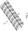
- FIG. 3 illustrates a perspective view of an example release line 326 and a medical device 106 in accordance with an embodiment.
- a delivery system 100 may include a release line 326 to the medical device 106 to the delivery system 100.
- the release line 326 may also be used to secure a steering line 220 or multiple steering lines (e.g., each similar to another as desired) to the delivery system 100.
- the release line 326 may be arranged external to the medical device 106 (as shown), may be internal to the medical device 106, or may be routed through the medical device 106 such that portions of the release line 326 are external to the medical device 106 and other portions of the release line 326 are internal to the medical device 106.
- Another end of the release line 326 similar to the coupling member 224 and steering line 220 discussed above, may be coupled to a handle 108 (not shown) of the delivery system 100. At the handle 108, tension may be applied to the release line 326 by a user to remove the release line 326 from the patient and uncouple the medical device 106 from the delivery system 100.
- the release line 326 can be formed from metallic, polymeric or natural materials and can comprise conventional medical grade materials such as nylon, polyacrylamide, polycarbonate, polyethylene, polyformaldehyde, polymethylmethacrylate, polypropylene, polytetrafluoroethylene, polytrifluorochlorethylene, polyvinylchloride, polyurethane, elastomeric organosilicon polymers; metals such as stainless steels, cobalt-chromium alloys and nitinol.
- conventional medical grade materials such as nylon, polyacrylamide, polycarbonate, polyethylene, polyformaldehyde, polymethylmethacrylate, polypropylene, polytetrafluoroethylene, polytrifluorochlorethylene, polyvinylchloride, polyurethane, elastomeric organosilicon polymers
- metals such as stainless steels, cobalt-chromium alloys and nitinol.
- Elongated members or lock wires can also be formed from high strength polymer fibers such as ultra high molecular weight polyethylene fibers (e.g., Spectra ® , Dyneema Purity ® , etc.) or aramid fibers (e.g., Technora ® , etc.).
- high strength polymer fibers such as ultra high molecular weight polyethylene fibers (e.g., Spectra ® , Dyneema Purity ® , etc.) or aramid fibers (e.g., Technora ® , etc.).
- FIG. 4 illustrates a side view of an example release line 326 and a catheter shaft 102 in accordance with an embodiment.
- a delivery system 100 incudes a catheter shaft 102, medical device 106, steering lines 220, and a release line 326.
- the release line 326 passes from outside of the body of the patient, from a handle 108 (not shown), through the catheter shaft 102, and exits distal to or near a distal end of the medical device 106. At this point, the release line 326 may extend along an exterior surface of the medical device 106.
- the release line 326 interacts with steering lines 220 continues to catheter tip 428.
- the release line 326 releasably couples steering lines 220 to the delivery system 100.
- the release line 326 may be embedded, affixed, or attached to the catheter tip 428, and may be released from the catheter tip 428 in response to tension applied to the release line 326 by a user. Any manner in which the release line 326 may interact with steering line or lines 220 to maintain a releasable coupling between steering line or lines 220 and the delivery system 100 is within the scope of the present disclosure.
- two steering lines 220 are shown, it should be understood any number of steering lines 220 is contemplated, including fewer or greater than the two shown in FIG. 4 .
- FIG. 5 illustrates a close-up view of a flexible loop 530, a medical device 106, and a catheter shaft 102 (that the medical device 106 is crushed or constrained onto) in accordance with an embodiment.
- the medical device 106 includes an opening 532.
- the opening 532 through the medical device 106 may be configured to allow the flexible loop 530 to extend from an interior of the medical device 106 (through which the catheter shaft 102 is arranged) to an exterior of the medical device 106 as shown in FIG. 5 .
- the opening 532 through the medical device 106 may be configured to allow the flexible loop 530 to extend from an exterior of the medical device 106 to an interior of the medical device 106.
- the medical device 106 may be collapsed to a delivery configuration for delivery and expanded at the target location. In certain instances, the medical device 106 may be partially expanded (e.g., for steering or orienting) or remain otherwise coupled to the catheter shaft during deployment. To maintain coupling of the medical device 106 to the catheter shaft 102, the delivery system may include a release line 326 (as shown in FIGs. 3-4 and FIG. 7 ) coupled to the medical device 106 and the catheter shaft 102.
- the release line 326 can increase an overall delivery profile of the system 100 due in part to the requirement for a catheter lumen to maintain the release line.
- a flexible loop 530 may serve as a pathway for the release line 326.
- the delivery systems discussed herein may include multiple flexible loops 530.
- the flexible loop 530 (or flexible loops 530) may form a flexible lumen through which the release line 326 is arranged.
- the flexible loop 530 may be attached to the catheter shaft 102 (as shown in FIG. 6 ).
- the flexible loop 530 (flexible loops 530 or lumen) may be configured to collapse in response to reduction in diameter of the medical device 106.
- the flexible loop 530 (flexible loops 530 or lumen) may facilitate delivery by forming a pathway or lumen for a release wire.
- the flexible loop 530 (flexible loops 530 or lumen) lessen a size or diameter of a catheter usable for the delivery systems discussed herein by forming a pathway for a release wire where a lumen of a catheter would previously been used.
- the flexible loop 530 (flexible loops 530 or lumen) may hold the release line 326 or similar feature in place exterior to the medical device 106 by being passed through the flexible loop 530.
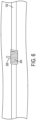
- FIG. 6 illustrates a close-up view of an example flexible loop 530 and a catheter shaft 102 in accordance with an embodiment.
- the flexible loop 530 is coupled to the catheter shaft 102.
- the flexible loop 530 may be attached to the catheter shaft 102 along a portion of the catheter shaft 102 that extends through a lumen of a medical device, such as the medical device 106.
- the flexible loop 530 includes a fiber 634 coupled to the catheter shaft 102.
- the fiber 634 may be wrapped, glued, bonded, sewn, tacked, interlocked or otherwise coupled to the catheter shaft 102 to form the flexible loop 530.
- the medical device 106 (as discussed above but not shown) discussed herein may be a stent and graft combination, or any configuration described in association with the medical device 106.
- the flexible loop 530 may be formed of the same or a similar material as the graft material of the medical device.
- the opening through which the flexible loop 530 is arranged may be arranged through the graft portion of the medical device 106.
- the flexible loop 530 is coupled to the catheter shaft 102 (e.g., wrapping, gluing, bonding, sewing, tacking, interlocking, or otherwise coupling the fiber 634 to the catheter shaft 102 to form the flexible loop 530).
- the flexible loop 530 is arranged through an opening (e.g., as shown in FIG. 5 ) in the medical device 106.
- a release line may be arranged through the flexible loop 530 to releasably couple the medical device to the catheter shaft 102 (e.g., as shown in FIG. 7 ).
- the medical device may be collapsed against the catheter shaft 102 to a delivery configuration, which can also include collapsing of the flexile loop 530 toward the catheter shaft 102 in response to the medical device being collapsed to the delivery configuration.
- FIG. 7 illustrates a side view of an example release line 326, flexible loop 530, and a catheter shaft 102 in accordance with an embodiment.
- the release line 326, flexible loop 530, and catheter shaft 102 form portions of a delivery system 100.
- the medical device 106 has an interior and an exterior. As shown in FIG. 7 , a portion of the catheter shaft 102 is arranged through the interior of the medical device 106, and the release line 326 is arranged across the exterior of the medical device 106.
- the delivery system 100 includes two flexible loops 530.
- the two flexible loops 530 are aligned relative to a longitudinal axis of the medical device 106, which may be aligned with the catheter shaft 102.
- the medical device 106 is configured to collapse to a delivery configuration from an expanded/delivery configuration shown in FIG. 7 .
- the flexible loop 530 or flexible loops 530 are configured to collapse toward the catheter shaft 102 in response to the medical device 106 being collapsed to the delivery configuration.
- the delivery system 100 may include one or more sheaths/sleeves (e.g., as shown in FIGs. 1-2 ) configured to releasably hold the medical device 106 in the delivery configuration.
- the flexible loop 530 (or loops 530) is configured to maintain at least a portion of the release line 326 in contact with an exterior surface of the medical device 106.
- the flexible loop 530 is configured to form a lumen for the release line 326 in certain instances.
- the flexible loop 530 (or flexible loops 530 as shown in FIG. 7 ) are attached to the catheter shaft 102 and extend through an opening 532 (or opening 532 for each respective flexible loop 530) through the medical device 106.
- the flexible loop 530 (or lumen) is configured to collapse in response to reduction in diameter of the medical device 106.
- the lumen is formed by a first loop 530 arranged at one of the medical device 106 and a second loop 530 arranged at another end of the medical device 106, with the release line 326 being arranged through the flexible lumen (formed by the loops 530).
- the release line 326 is configured to releasably couple the medical device 106 to the catheter shaft 102.
- the release line 326 may terminate at a catheter tip 428 (or olive) of the catheter shaft 102.
- the release line 326 is configured to release from the catheter tip 428 (or olive) in response to tension and withdraw through the flexible loop(s) 530.
- the medical device 106 may be collapsed to a delivery configuration for delivery and expanded at the target location. In certain instances, the medical device 106 may be partially expanded (e.g., for steering or orienting) or remain otherwise coupled to the catheter shaft during deployment.
- the release line 326 is coupled to the medical device 106 by being arranged through the flexible loop(s) 530 (or lumen) and to the catheter shaft 102.
- the medical device 106 may be partially expanded and maintained in contact with the delivery system 100 and the catheter shaft 102 by way of the release line 326.
- the release line 326 and the loop(s) 539 are configured to maintain the medical device 106 coupled to the catheter shaft 102 during orientation of the medical device 106.
- the flexible loop(s) 530 facilitate a minimal delivery profile of the system 100 due in part to removing the need for a lumen for the catheter lumen for the release line 326 (which can add to overall delivery size).
- the flexible loop 530 (or flexible loops 530) may form a flexible lumen through which the release line 326 is arranged, and which may collapse along with the medical device 106.
- the release line 326 is configured to withdrawn through the flexible loop(s) 530 in response to tension.
- the flexible loop(s) 530 are fixedly coupled to the catheter shaft 106.
- the catheter shaft 102 may be removed from the vasculature after deployment of the medical device 106 and leave the medical device 106 at the target treatment location.
- the catheter shaft 102 may be withdrawn to remove the system 100 from the vasculature.
- the flexible loop(s) 530 are also removed due to the flexible loop(s) 530 being fixedly attached to the catheter shaft 102.
- the flexible loop(s) facilitate use of the release line 326 without increasing the size of the delivery system 100, which may facilitate use of the system 100 through reach into smaller vasculature as compared to prior systems.
- graft members of the medical devices discussed herein include, for example, expanded polytetrafluoroethylene (ePTFE), polyester, polyurethane, fluoropolymers, such as perflouorelastomers and the like, polytetrafluoroethylene, silicones, urethanes, ultra-high molecular weight polyethylene, aramid fibers, and combinations thereof.
- a graft member material can include high strength polymer fibers such as ultra-high molecular weight polyethylene fibers (e.g., Spectra ® , Dyneema Purity ® , etc.) or aramid fibers (e.g., Technora ® , etc.).
- the graft member may include a bioactive agent.
- an ePTFE graft includes a carbon component along a blood contacting surface thereof. Any graft member which can be delivered by a catheter is in accordance with the present disclosure.
- stent components of the medical devices discussed herein can have various configurations such as, for example, rings, cut tubes, wound wires (or ribbons) or flat patterned sheets rolled into a tubular form.
- Stent components can be formed from metallic, polymeric or natural materials and can comprise conventional medical grade materials such as nylon, polyacrylamide, polycarbonate, polyethylene, polyformaldehyde, polymethylmethacrylate, polypropylene, polytetrafluoroethylene, polytrifluorochlorethylene, polyvinylchloride, polyurethane, elastomeric organosilicon polymers; metals such as stainless steels, cobalt-chromium alloys and nitinol and biologically derived materials such as bovine arteries/veins, pericardium and collagen.
- Stent components can also comprise bioresorbable materials such as poly(amino acids), poly(anhydrides), poly(caprolactones), poly(lactic/glycolic acid) polymers, poly(hydroxybutyrates) and poly(orthoesters). Any expandable stent component configuration which can be delivered by a catheter is in accordance with the present disclosure.
Landscapes
- Health & Medical Sciences (AREA)
- Engineering & Computer Science (AREA)
- Biomedical Technology (AREA)
- Cardiology (AREA)
- Oral & Maxillofacial Surgery (AREA)
- Transplantation (AREA)
- Heart & Thoracic Surgery (AREA)
- Vascular Medicine (AREA)
- Life Sciences & Earth Sciences (AREA)
- Animal Behavior & Ethology (AREA)
- General Health & Medical Sciences (AREA)
- Public Health (AREA)
- Veterinary Medicine (AREA)
- Media Introduction/Drainage Providing Device (AREA)
- Prostheses (AREA)
Abstract
Various aspects of the present disclosure are directed toward apparatuses, systems, and methods for medical device delivery. The apparatuses, systems, and methods may include at least one loop attached to a catheter shaft and extending through a medical device and a release line held in place by passing through the loop.
Description
- The present invention relates to medical devices and methods for treating an anatomical space (e.g., vessels) of the body. More specifically, the invention relates to methods, apparatuses, and systems that include an implantable medical device prosthesis that allows for accurate deployment in the anatomical space.
- Disease of the vasculature is increasingly common. Treatment of the vasculature may be difficult because of the tortuous nature and complexity of the vasculature. Aortic dissections, for example, commonly begin at or near the aortic valve root and continue to the ascending aorta and the aortic arch. Medical devices implanted at a diseased state may be used for treatment of aortic dissections, aneurysms, and other diseases of the vasculature or other luminal systems of the body, such as the biliary tract, gastrointestinal tract, or respiratory system, for example.
- It remains desirable to provide medical devices, systems and methods for repairing disease along the aorta and also for repairing disease along the aorta and the branches extending and luminal spaces therefrom.
- In one example ("Example 1"), a medical device delivery system includes a catheter shaft; at least one loop attached to the catheter shaft; a medical device having an interior and an exterior; at least one opening through the medical device configured to allow the loop to extend from the interior to the exterior of the medical device; and a release line exterior to the medical device held in place by passing through the loop.
- In another example ("Example 2"), further to the system of Example 1, the at least one loop is flexible and includes at least two flexible loops aligned relative to a longitudinal axis of the medical device.
- In another example ("Example 3"), further to the system of any one of Examples 1-2, the at least one flexible loop includes a fiber coupled to the catheter shaft.
- In another example ("Example 4"), further to the system of Example 3, the fiber is at least one of wrapped, glued, and bonded to the catheter shaft to form the at least one flexible loop.
- In another example ("Example 5"), further to the system of any one of Examples 1-4, the medical device is configured to collapse to a delivery configuration and the at least one flexible loop is configured to collapse toward the catheter shaft in response to the medical device being collapse to the delivery configuration.
- In another example ("Example 6"), further to the system of Example 5, the system also includes at least one sheath configured to releasably hold the medical device in the delivery configuration.
- In another example ("Example 7"), further to the system of any one of Examples 1-6, the medical device comprises a stent and graft combination and the at least one opening is formed through the graft, and the at least one flexible loop comprises a graft material.
- In another example ("Example 8"), further to the system of any one of Examples 1-7, the at least one flexible loop is configured to maintain at least a portion of the release line in contact with an exterior surface of the medical device.
- In another example ("Example 9"), further to the system of any one of Examples 1-8, the at least one flexible loop is configured to form a lumen for the release line.
- In another example ("Example 10"), further to the system of any one of Examples 1-9, the release line terminates in an olive at one end of the catheter shaft.
- In another example ("Example 11"), further to the system of Example 10, the release line is configured to release from the olive in response to tension and withdraw through the at least one flexible loop.
- In another example ("Example 12"), further to the system of any one of Examples 1-11, the release line and the at least one loop are configured to maintain the medical device coupled to the catheter shaft during orientation of the medical device.
- In one example ("Example 13"), a method of manufacturing a delivery system for a medical device includes coupling at least one flexible loop to a catheter shaft; arranging the at least one flexible loop through an opening in the medical device; and arranging a release line through the at least one flexible loop to releasably couple the medical device to the catheter shaft.
- In another Example ("Example 14"), further to the method of Example 13, coupling the at least one flexible loop to the catheter shaft includes at least one of wrapping, gluing, and bonding a fiber to the catheter shaft to form the at least one flexible loop.
- In another example ("Example 15"), further to the method of any one of Examples 13-14, the method also includes collapsing the medical device against the catheter shaft to a delivery configuration and collapsing the at least one flexile loop toward the catheter shaft in response to the medical device being collapse to the delivery configuration.
- In another example ("Example 16") a medical device delivery system includes a catheter shaft; a medical device having an interior and an exterior; a flexible lumen attached to the catheter shaft and extending through at least one opening through the medical device, the flexible lumen being configured to collapse in response to reduction in diameter of the medical device; and a release line arranged through the flexible lumen and configured to releasably couple the medical device to the catheter shaft.
- In another example ("Example 17"), further to the system of Example 16, the flexible lumen includes a first flexible loop and a second flexible loop arranged at opposite ends of the medical device.
- In another example ("Example 18"), further to the system of Example 17, the release line is configured to withdrawn through the first flexible loop and the second flexible loop in response to tension, and the first flexible loop and the second flexible loop maintain coupled to the catheter shaft.
- In another example ("Example 19"), further to the system of Example 18, the catheter shaft is configured to withdraw the first flexible loop and the second flexible loop after delivery of the medical device.
- In another example ("Example 20"), further to the system of Example 16, the at least one flexible loop includes a fiber coupled to the catheter shaft and the fiber is at least one of wrapped, glued, and bonded to the catheter shaft to form the at least one flexible loop.
- The accompanying drawings are included to provide a further understanding of the disclosure and are incorporated in and constitute a part of this specification, illustrate embodiments, and together with the description serve to explain the principles of the disclosure.
-
FIG. 1 illustrates a side view of an example delivery system having a medical device in accordance with an embodiment. -
FIG. 2 illustrates a perspective view of an example delivery system having a medical device in accordance with an embodiment. -
FIG. 3 illustrates a perspective view of an example release line and a medical device in accordance with an embodiment. -
FIG. 4 illustrates a side view of an example release line and a catheter shaft in accordance with an embodiment. -
FIG. 5 illustrates a close-up view of an example flexible loop, a medical device, and a catheter shaft in accordance with an embodiment. -
FIG. 6 illustrates a close-up view of an example flexible loop and a catheter shaft in accordance with an embodiment. -
FIG. 7 illustrates a side view of an example release line, flexible loop, and a catheter shaft in accordance with an embodiment. - Persons skilled in the art will readily appreciate that various aspects of the present disclosure can be realized by any number of methods and apparatus configured to perform the intended functions. It should also be noted that the accompanying drawing figures referred to herein are not necessarily drawn to scale, but may be exaggerated to illustrate various aspects of the present disclosure, and in that regard, the drawing figures should not be construed as limiting.
- Various aspects of the present disclosure are directed toward apparatuses, systems, and methods that include an implantable medical device that may be used in treatment of the vasculature or other luminal and non-luminal systems of the body. In some examples, the implantable medical device is delivered to the vasculature using a delivery system, such as a transcatheter delivery system. In terms of configurations for the implantable medical device, a variety of configurations are contemplated, and the implantable medical devices described herein may be substantially cylindrical, include a bifurcation, or have any of a variety of features. Further, the implantable medical devices may be configured to conform to the vasculature into which the implantable medical device is implanted, and have a profile that facilitates delivery of the implantable medical device using a minimally invasive procedure (e.g., via transcatheter techniques), and able to withstand forces and other stresses that occur once implanted in the vasculature.
- The medical device may be collapsed to a delivery configuration for delivery and expanded at the target location. In certain instances, the medical device may be partially expanded (e.g., for steering or orienting) or remain otherwise coupled to the catheter shaft during deployment. To maintain coupling of the medical device to the catheter, the delivery system may include a release line coupled to the medical device and the catheter.
- As compared to delivery systems without a structural aspect to releasably couple a medical device to a catheter shaft, the release line, in certain instances, can increase an overall delivery profile of the system due in part to a catheter lumen for the release line. To facilitate delivery of the medical device with a release line (or other similar device-to-catheter coupling), the systems discussed herein include a flexible loop or lumen through which the release line is arranged. As discussed in further detail below, the flexible loop or lumen facilitate delivery of the medical devices discussed herein.
-
FIG. 1 illustrates a side view of anexample delivery system 100 having amedical device 106 in accordance with an embodiment. Themedical device 106 may be any endoluminal device suitable for delivery to the treatment area of a vasculature, or other luminal and non-luminal systems of the body (biliary tract, GI tract, respiratory system, or other as desired). As shown inFIG. 1 , thedelivery system 100 may also include ahandle 108 at a proximal end of the system (the opposite end of the system at which themedical device 106 is arranged). Thehandle 108 of thedelivery system 100 may be accessible to a user to assist in delivering themedical device 106. As explained in further detail below, thedelivery system 100 may include one or more lines or wires that facilitate delivery, orientation, or placement of themedical device 106. - In various embodiments, the
medical device 106 can include a radially collapsed configuration suitable for delivery to the treatment area of the vasculature of a patient. Themedical device 106 can be constrained toward a radially collapsed configuration and releasably mounted onto a delivery device such ascatheter shaft 102. The diameter of themedical device 106 in the collapsed configuration is small enough for themedical device 106 to be delivered through the vasculature to a target treatment location or area. In various embodiments, the diameter of the collapsed configuration is small enough to minimize the crossing profile of thedelivery system 100 and reduce or prevent tissue damage to the patient. In the collapsed configuration, themedical device 106 can be guided by acatheter shaft 102 through the vasculature. - The
medical device 106 can comprise a radially expanded configuration suitable for implanting themedical device 106 in the treatment area of a patient's vasculature. In the expanded configuration, the diameter of themedical device 106 can be approximately the same as the vessel or other body lumen in which themedical device 106 is to be placed. In other embodiments, the diameter of themedical device 106 in the expanded configuration can be slightly larger than the vessel to be treated to provide a friction or interference fit within the vessel. - In various embodiments,
medical device 106 can comprise a self-expandable device, such as a self-expandable stent graft. Such devices dilate from a radially collapsed configuration to a radially expanded configuration when unrestrained. In other embodiments,medical device 106 can comprise a device that is expanded with the assistance of a secondary device applying an expansion force on themedical device 106, such as, for example, a balloon. In yet other embodiments,delivery system 100 can comprise a plurality ofmedical devices 106. The use of thedelivery system 100 with any number ofmedical devices 106 is within the scope of the present disclosure. Themedical devices 106 discussed herein may include, for example, stents, grafts, stent grafts, heart valves, and other similar devices. Thus,medical device 106 can include one or more stent components with one or more graft members disposed over and/or under the stent, which can dilate from a delivery diameter, through a range of larger intermediary diameters, and toward a maximal, pre-determined functional diameter. In certain instances, themedical device 106 includes one or more stent components made of nitinol and a graft member made of ePTFE. However, and as discussed below, any suitable combination of stent component(s) and graft member(s) is within the scope of the present disclosure. - In certain instances, the
delivery system 100 may include a sleeve or multiple sleeves (and other constrain mechanisms) to constrain themedical device 106 in a collapsed configuration for endoluminal delivery of themedical device 106 to a treatment portion of the vasculature or other body lumen of a patient. For the purposes of the disclosure, the term "constrain" may mean (i) to limit the expansion, either through self-expansion or assisted by a device, of the diameter of amedical device 106 or (ii) to cover or surround but not otherwise restrain a medical device 106 (e.g., for storage or biocompatibility reasons and/or to provide protection to themedical device 106 and/or the vasculature). Thedelivery system 100, for example, comprises a sleeve 104 (or pull-back sheath or other similar constraining structure) which surrounds and constrainsmedical device 106 toward a reduced diameter or collapsed configuration as shown in further detail with reference toFIG. 2 . -
FIG. 2 illustrates a perspective view of anexample delivery system 100 having amedical device 106 in accordance with an embodiment. In various embodiments, themedical device 106 is constrained by asingle sleeve 104 which circumferentially surrounds themedical device 106. In various embodiments, thesleeve 104 circumferentially surrounds themedical device 106 and constrains it toward a collapsed configuration, in which the diameter is less than the diameter of themedical device 106 in an unconstrained or otherwise deployed state or configuration. For example, thesleeve 104 may constrain themedical device 106 toward a collapsed configuration for delivery within the vasculature. - In other embodiments, the
medical device 106 is constrained by a plurality of sleeves (e.g., similar to the sleeve 104) which circumferentially surround themedical device 106, which allow themedical device 106 to be deployed and held at intermediate configurations larger than the collapsed configuration and smaller than the deployed configuration. The plurality of sleeves can comprise at least two sleeves (e.g., each similar to sleeve 104) which circumferentially surround each other. - The sheet of material(s) used to form the sleeve(s) can comprise a series of openings, such that the openings extend from one edge of the sheet to the other. In such configurations, a
coupling member 224 can be woven or stitched through the series of openings in the sheet of material(s), securing each of the two edges together and forming a tube. For example, inFIG. 2 , thecoupling member 224 secures the edges ofsleeve 104 such thatsleeve 104 maintainsmedical device 106 toward a reduced diameter or outer peripheral dimension suitable for endoluminal delivery. - In various embodiments, disengaging a single coupling member which closes a single sleeve from the sleeve allows the expandable device to be expanded toward a larger diameter or outer peripheral dimension. For example, with reference to
FIG. 2 , the delivery system can be used to deliver themedical device 106 to a treatment area of a vasculature. Themedical device 106 has a collapsed diameter for delivery, andsleeve 104 circumferentially surrounds themedical device 106 and is held closed by thecoupling member 224. As described in more detail below, bending of themedical device 106 can be controlled prior to full expansion (e.g., at an intermediate diameter) to help facilitate delivery to the desired position. Oncemedical device 106 is in position relative to the treatment area, thecoupling member 224 is disengaged from thesleeve 104 and thesleeve 104 is released, allowingmedical device 106 to expand toward a larger diameter. - In such embodiments, the
medical device 106 can be expanded from the collapsed configuration toward the intermediate configuration once the implant has been delivered near the treatment area of the vasculature of a patient. The intermediate configuration may, among other things, assist in properly orienting and locating themedical device 106 within the treatment area of the vasculature. In various embodiments, amedical device 106 can be concentrically surrounded by two sleeves having different diameters. In such configurations, a primary sleeve constrains themedical device 106 toward the collapsed configuration. Once the collapsed configuration sleeve is opened, a secondary sleeve constrains themedical device 106 toward the intermediate configuration similarly configured and arranged as the sleeve 104 (e.g., the secondary sleeve may also be held together released by a coupling member). - As noted above, the
medical device 106 may be oriented at the treatment area of the vasculature. To orient themedical device 106, thedelivery system 100 includes asteering line 220. Tension can be applied to thesteering line 220 to displace thesteering line 220 and bend themedical device 106. Bending themedical device 106 may, among other things, assist in travelling through curved or tortuous regions of vasculature. Bending themedical device 106 may also allow themedical device 106 to conform to curvatures in the vasculature, or other body lumens of a patient. - In certain instances, the
delivery system 100 may include a handle 108 (as shown inFIG. 1 ) to which thecoupling member 224 and the steering line 220 (or lines) are connected. Thehandle 108 may allow the user to manipulate thecoupling member 224 and thesteering line 220 outside of the patient. -
FIG. 3 illustrates a perspective view of anexample release line 326 and amedical device 106 in accordance with an embodiment. Adelivery system 100 may include arelease line 326 to themedical device 106 to thedelivery system 100. In addition, therelease line 326 may also be used to secure asteering line 220 or multiple steering lines (e.g., each similar to another as desired) to thedelivery system 100. - The
release line 326 may be arranged external to the medical device 106 (as shown), may be internal to themedical device 106, or may be routed through themedical device 106 such that portions of therelease line 326 are external to themedical device 106 and other portions of therelease line 326 are internal to themedical device 106. Another end of therelease line 326, similar to thecoupling member 224 andsteering line 220 discussed above, may be coupled to a handle 108 (not shown) of thedelivery system 100. At thehandle 108, tension may be applied to therelease line 326 by a user to remove therelease line 326 from the patient and uncouple themedical device 106 from thedelivery system 100. - In various embodiments, the
release line 326 can be formed from metallic, polymeric or natural materials and can comprise conventional medical grade materials such as nylon, polyacrylamide, polycarbonate, polyethylene, polyformaldehyde, polymethylmethacrylate, polypropylene, polytetrafluoroethylene, polytrifluorochlorethylene, polyvinylchloride, polyurethane, elastomeric organosilicon polymers; metals such as stainless steels, cobalt-chromium alloys and nitinol. Elongated members or lock wires can also be formed from high strength polymer fibers such as ultra high molecular weight polyethylene fibers (e.g., Spectra®, Dyneema Purity®, etc.) or aramid fibers (e.g., Technora®, etc.). -
FIG. 4 illustrates a side view of anexample release line 326 and acatheter shaft 102 in accordance with an embodiment. As shown inFIG. 4 , adelivery system 100 incudes acatheter shaft 102,medical device 106, steeringlines 220, and arelease line 326. Therelease line 326 passes from outside of the body of the patient, from a handle 108 (not shown), through thecatheter shaft 102, and exits distal to or near a distal end of themedical device 106. At this point, therelease line 326 may extend along an exterior surface of themedical device 106. - In certain instances and as shown in
FIG. 4 , therelease line 326 interacts with steeringlines 220 continues tocatheter tip 428. In such a configuration, therelease line 326 releasablycouples steering lines 220 to thedelivery system 100. Therelease line 326 may be embedded, affixed, or attached to thecatheter tip 428, and may be released from thecatheter tip 428 in response to tension applied to therelease line 326 by a user. Any manner in which therelease line 326 may interact with steering line orlines 220 to maintain a releasable coupling between steering line orlines 220 and thedelivery system 100 is within the scope of the present disclosure. Although two steeringlines 220 are shown, it should be understood any number ofsteering lines 220 is contemplated, including fewer or greater than the two shown inFIG. 4 . -
FIG. 5 illustrates a close-up view of aflexible loop 530, amedical device 106, and a catheter shaft 102 (that themedical device 106 is crushed or constrained onto) in accordance with an embodiment. As shown inFIG. 5 , themedical device 106 includes anopening 532. Theopening 532 through themedical device 106 may be configured to allow theflexible loop 530 to extend from an interior of the medical device 106 (through which thecatheter shaft 102 is arranged) to an exterior of themedical device 106 as shown inFIG. 5 . In certain instances, theopening 532 through themedical device 106 may be configured to allow theflexible loop 530 to extend from an exterior of themedical device 106 to an interior of themedical device 106. - The
medical device 106 may be collapsed to a delivery configuration for delivery and expanded at the target location. In certain instances, themedical device 106 may be partially expanded (e.g., for steering or orienting) or remain otherwise coupled to the catheter shaft during deployment. To maintain coupling of themedical device 106 to thecatheter shaft 102, the delivery system may include a release line 326 (as shown inFIGs. 3-4 andFIG. 7 ) coupled to themedical device 106 and thecatheter shaft 102. - As compared to delivery systems without a structural aspect (e.g., a release wire, lock wire, or other similar structure) to releasably couple the
medical device 106 to thecatheter shaft 102, therelease line 326, in certain instances, can increase an overall delivery profile of thesystem 100 due in part to the requirement for a catheter lumen to maintain the release line. To facilitate delivery of themedical device 106 with a release line (or other similar device-to-catheter coupling), aflexible loop 530 may serve as a pathway for therelease line 326. In certain instances, the delivery systems discussed herein may include multipleflexible loops 530. In certain instances, the flexible loop 530 (or flexible loops 530) may form a flexible lumen through which therelease line 326 is arranged. - In certain instances, the flexible loop 530 (flexible loops 530) may be attached to the catheter shaft 102 (as shown in
FIG. 6 ). The flexible loop 530 (flexible loops 530 or lumen) may be configured to collapse in response to reduction in diameter of themedical device 106. In this manner, the flexible loop 530 (flexible loops 530 or lumen) may facilitate delivery by forming a pathway or lumen for a release wire. Thus, the flexible loop 530 (flexible loops 530 or lumen) lessen a size or diameter of a catheter usable for the delivery systems discussed herein by forming a pathway for a release wire where a lumen of a catheter would previously been used. As shown in further detail inFIG. 7 , the flexible loop 530 (flexible loops 530 or lumen) may hold therelease line 326 or similar feature in place exterior to themedical device 106 by being passed through theflexible loop 530. -
FIG. 6 illustrates a close-up view of an exampleflexible loop 530 and acatheter shaft 102 in accordance with an embodiment. As shown inFIG. 6 , theflexible loop 530 is coupled to thecatheter shaft 102. Theflexible loop 530 may be attached to thecatheter shaft 102 along a portion of thecatheter shaft 102 that extends through a lumen of a medical device, such as themedical device 106. - In certain instances, the
flexible loop 530 includes afiber 634 coupled to thecatheter shaft 102. Thefiber 634 may be wrapped, glued, bonded, sewn, tacked, interlocked or otherwise coupled to thecatheter shaft 102 to form theflexible loop 530. The medical device 106 (as discussed above but not shown) discussed herein may be a stent and graft combination, or any configuration described in association with themedical device 106. Theflexible loop 530 may be formed of the same or a similar material as the graft material of the medical device. In addition, the opening through which theflexible loop 530 is arranged may be arranged through the graft portion of themedical device 106. - To manufacture a delivery system that includes the
flexible loop 530 or more than oneflexible loop 530, theflexible loop 530 is coupled to the catheter shaft 102 (e.g., wrapping, gluing, bonding, sewing, tacking, interlocking, or otherwise coupling thefiber 634 to thecatheter shaft 102 to form the flexible loop 530). After theflexible loop 530 is formed, theflexible loop 530 is arranged through an opening (e.g., as shown inFIG. 5 ) in themedical device 106. Subsequently, a release line may be arranged through theflexible loop 530 to releasably couple the medical device to the catheter shaft 102 (e.g., as shown inFIG. 7 ). After the release line is arranged through theflexible loop 530, the medical device may be collapsed against thecatheter shaft 102 to a delivery configuration, which can also include collapsing of theflexile loop 530 toward thecatheter shaft 102 in response to the medical device being collapsed to the delivery configuration. -
FIG. 7 illustrates a side view of anexample release line 326,flexible loop 530, and acatheter shaft 102 in accordance with an embodiment. Therelease line 326,flexible loop 530, andcatheter shaft 102 form portions of adelivery system 100. Themedical device 106 has an interior and an exterior. As shown inFIG. 7 , a portion of thecatheter shaft 102 is arranged through the interior of themedical device 106, and therelease line 326 is arranged across the exterior of themedical device 106. - As shown in
FIG. 7 , thedelivery system 100 includes twoflexible loops 530. In certain instances, the twoflexible loops 530 are aligned relative to a longitudinal axis of themedical device 106, which may be aligned with thecatheter shaft 102. Further, themedical device 106 is configured to collapse to a delivery configuration from an expanded/delivery configuration shown inFIG. 7 . In these instances, theflexible loop 530 orflexible loops 530 are configured to collapse toward thecatheter shaft 102 in response to themedical device 106 being collapsed to the delivery configuration. Thedelivery system 100 may include one or more sheaths/sleeves (e.g., as shown inFIGs. 1-2 ) configured to releasably hold themedical device 106 in the delivery configuration. - In certain instances, the flexible loop 530 (or loops 530) is configured to maintain at least a portion of the
release line 326 in contact with an exterior surface of themedical device 106. Thus, theflexible loop 530 is configured to form a lumen for therelease line 326 in certain instances. The flexible loop 530 (orflexible loops 530 as shown inFIG. 7 ) are attached to thecatheter shaft 102 and extend through an opening 532 (or opening 532 for each respective flexible loop 530) through themedical device 106. The flexible loop 530 (or lumen) is configured to collapse in response to reduction in diameter of themedical device 106. In certain instances, the lumen is formed by afirst loop 530 arranged at one of themedical device 106 and asecond loop 530 arranged at another end of themedical device 106, with therelease line 326 being arranged through the flexible lumen (formed by the loops 530). Therelease line 326 is configured to releasably couple themedical device 106 to thecatheter shaft 102. - In certain instances and as shown in
FIG. 4 , therelease line 326 may terminate at a catheter tip 428 (or olive) of thecatheter shaft 102. Therelease line 326 is configured to release from the catheter tip 428 (or olive) in response to tension and withdraw through the flexible loop(s) 530. As noted above, themedical device 106 may be collapsed to a delivery configuration for delivery and expanded at the target location. In certain instances, themedical device 106 may be partially expanded (e.g., for steering or orienting) or remain otherwise coupled to the catheter shaft during deployment. To maintain coupling of themedical device 106 to thecatheter shaft 102, therelease line 326 is coupled to themedical device 106 by being arranged through the flexible loop(s) 530 (or lumen) and to thecatheter shaft 102. Thus, themedical device 106 may be partially expanded and maintained in contact with thedelivery system 100 and thecatheter shaft 102 by way of therelease line 326. Therelease line 326 and the loop(s) 539 are configured to maintain themedical device 106 coupled to thecatheter shaft 102 during orientation of themedical device 106. - The flexible loop(s) 530, in certain instances, facilitate a minimal delivery profile of the
system 100 due in part to removing the need for a lumen for the catheter lumen for the release line 326 (which can add to overall delivery size). In certain instances, the flexible loop 530 (or flexible loops 530) may form a flexible lumen through which therelease line 326 is arranged, and which may collapse along with themedical device 106. - After orienting and deployment of the
medical device 106, therelease line 326 is configured to withdrawn through the flexible loop(s) 530 in response to tension. The flexible loop(s) 530 are fixedly coupled to thecatheter shaft 106. Thecatheter shaft 102 may be removed from the vasculature after deployment of themedical device 106 and leave themedical device 106 at the target treatment location. Thecatheter shaft 102 may be withdrawn to remove thesystem 100 from the vasculature. By withdrawing thecatheter shaft 102, the flexible loop(s) 530 are also removed due to the flexible loop(s) 530 being fixedly attached to thecatheter shaft 102. The flexible loop(s) facilitate use of therelease line 326 without increasing the size of thedelivery system 100, which may facilitate use of thesystem 100 through reach into smaller vasculature as compared to prior systems. - Potential materials for graft members of the medical devices discussed herein include, for example, expanded polytetrafluoroethylene (ePTFE), polyester, polyurethane, fluoropolymers, such as perflouorelastomers and the like, polytetrafluoroethylene, silicones, urethanes, ultra-high molecular weight polyethylene, aramid fibers, and combinations thereof. Other embodiments for a graft member material can include high strength polymer fibers such as ultra-high molecular weight polyethylene fibers (e.g., Spectra®, Dyneema Purity®, etc.) or aramid fibers (e.g., Technora®, etc.). The graft member may include a bioactive agent. In one embodiment, an ePTFE graft includes a carbon component along a blood contacting surface thereof. Any graft member which can be delivered by a catheter is in accordance with the present disclosure.
- In addition, stent components of the medical devices discussed herein can have various configurations such as, for example, rings, cut tubes, wound wires (or ribbons) or flat patterned sheets rolled into a tubular form. Stent components can be formed from metallic, polymeric or natural materials and can comprise conventional medical grade materials such as nylon, polyacrylamide, polycarbonate, polyethylene, polyformaldehyde, polymethylmethacrylate, polypropylene, polytetrafluoroethylene, polytrifluorochlorethylene, polyvinylchloride, polyurethane, elastomeric organosilicon polymers; metals such as stainless steels, cobalt-chromium alloys and nitinol and biologically derived materials such as bovine arteries/veins, pericardium and collagen. Stent components can also comprise bioresorbable materials such as poly(amino acids), poly(anhydrides), poly(caprolactones), poly(lactic/glycolic acid) polymers, poly(hydroxybutyrates) and poly(orthoesters). Any expandable stent component configuration which can be delivered by a catheter is in accordance with the present disclosure.
- The invention of this application has been described above both generically and with regard to specific embodiments. It will be apparent to those skilled in the art that various modifications and variations can be made in the embodiments without departing from the scope of the disclosure. Thus, it is intended that the embodiments cover the modifications and variations of this invention provided they come within the scope of the appended claims and their equivalents.
-
- Clause 1. A medical device delivery system, the system comprising:
- a catheter shaft;
- at least one loop attached to the catheter shaft;
- a medical device having an interior and an exterior;
- at least one opening through the medical device configured to allow the loop to extend from the interior to the exterior of the medical device; and
- a release line exterior to the medical device held in place by passing through the loop.
- Clause 2. The system of clause 1, wherein the at least one loop is flexible and includes at least two flexible loops aligned relative to a longitudinal axis of the medical device.
- Clause 3. The system of any one of clauses 1-2, wherein the at least one flexible loop includes a fiber coupled to the catheter shaft.
- Clause 4. The system of clause 3, wherein the fiber is at least one of wrapped, glued, and bonded to the catheter shaft to form the at least one flexible loop.
- Clause 5. The system of any one of clauses 1-4, wherein the medical device is configured to collapse to a delivery configuration and the at least one flexible loop is configured to collapse toward the catheter shaft in response to the medical device being collapse to the delivery configuration.
- Clause 6. The system of clause 5, further comprising at least one sheath configured to releasably hold the medical device in the delivery configuration.
- Clause 7. The system of any one of clauses 1-6, wherein the medical device comprises a stent and graft combination and the at least one opening is formed through the graft, and the at least one flexible loop comprises a graft material.
- Clause 8. The system of any one of clauses 1-7, wherein the at least one flexible loop is configured to maintain at least a portion of the release line in contact with an exterior surface of the medical device.
- Clause 9. The system of any one of clauses 1-8, wherein the at least one flexible loop is configured to form a lumen for the release line.
- Clause 10. The system of any one of clauses 1-9, wherein the release line terminates in an olive at one end of the catheter shaft.
- Clause 11. The system of clause 10, wherein the release line is configured to release from the olive in response to tension and withdraw through the at least one flexible loop.
- Clause 12. The system of any one of clauses 1-11, wherein the release line and the at least one loop are configured to maintain the medical device coupled to the catheter shaft during orientation of the medical device.
- Clause 13. A method of manufacturing a delivery system for a medical device, the method comprising:
- coupling at least one flexible loop to a catheter shaft;
- arranging the at least one flexible loop through an opening in the medical device; and
- arranging a release line through the at least one flexible loop to releasably couple the medical device to the catheter shaft.
- Clause 14. The method of clause 13, wherein coupling the at least one flexible loop to the catheter shaft includes at least one of wrapping, gluing, and bonding a fiber to the catheter shaft to form the at least one flexible loop.
- Clause 15. The method of any one of clauses 13-14, further comprising collapsing the medical device against the catheter shaft to a delivery configuration and collapsing the at least one flexile loop toward the catheter shaft in response to the medical device being collapse to the delivery configuration.
- Clause 16. A medical device delivery system, the system comprising:
- a catheter shaft;
- a medical device having an interior and an exterior;
- a flexible lumen attached to the catheter shaft and extending through at least one opening through the medical device, the flexible lumen being configured to collapse in response to reduction in diameter of the medical device; and
- a release line arranged through the flexible lumen and configured to releasably couple the medical device to the catheter shaft.
- Clause 17. The system of clause 16, wherein the flexible lumen includes a first flexible loop and a second flexible loop arranged at opposite ends of the medical device.
- Clause 18. The system of clause 17, wherein the release line is configured to withdrawn through the first flexible loop and the second flexible loop in response to tension, and the first flexible loop and the second flexible loop maintain coupled to the catheter shaft.
- Clause 19. The system of clause 18, wherein the catheter shaft is configured to withdraw the first flexible loop and the second flexible loop after delivery of the medical device.
- Clause 20. The system of clause 16, wherein the at least one flexible loop includes a fiber coupled to the catheter shaft and the fiber is at least one of wrapped, glued, and bonded to the catheter shaft to form the at least one flexible loop.
Claims (15)
- A medical device delivery system, the system comprising:a catheter shaft,a medical device coupled to the catheter shaft in a delivery configuration, the medical device having an interior and an exterior and at least one opening defined between the interior and the exterior;at least one flexible loop extending from the interior to the exterior and through the opening of the medical device; anda release line extending through the at least one flexible loop,wherein the at least one flexible loop is configured to maintain at least a portion of the release line in contact with an exterior surface of the medical device.
- The medical device delivery system of claim 1, wherein the medical device is configured to collapse to the delivery configuration, and when the medical device collapses, the at least one flexible loop is configured to collapse toward the catheter shaft.
- The medical delivery system of claim 1, further comprising at least one sheath configured to releasably hold the medical device in the delivery configuration.
- The medical delivery system of claim 3, wherein the at least one sheath includes a first sheath and a second sheath positioned under the first sheath, wherein when the first sheath is open, the second sheath constrains the device to an intermediate configuration between the delivery configuration and an expanded configuration.
- The medical delivery system of claim 1, wherein the at least one flexible loop includes a fiber; and optionally wherein the fiber is at least one of wrapped, glued, and bonded to the catheter shaft to form the at least one flexible loop.
- The medical delivery system of claim 1, wherein the medical device comprises a stent and graft combination and the at least one opening is formed through the graft;
and optionally wherein the at least one flexible loop comprises a material that is the same or similar to the graft material. - The medical delivery system of claim 1, wherein the release line terminates in an olive at one end of the catheter shaft; and optionally wherein the release line is configured to release from the olive in response to tension and withdraw through the at least one flexible loop.
- The medical delivery system of claim 1, wherein the release line and the at least one loop are configured to maintain the medical device coupled to the catheter shaft during orientation of the medical device.
- The medical delivery system of claim 1, wherein the at least one loop includes at least two flexible loops aligned relative to a longitudinal axis of the medical device such that the release line extends along a portion of the longitudinal axis of the medical device.
- A method of manufacturing a delivery system for a medical device, the method comprising:arranging the at least one flexible loop through an opening in the medical device; andarranging a release line through the at least one flexible loop to releasably couple the medical device to the catheter shaft,wherein the at least one flexible loop is configured to maintain at least a portion of the release line in contact with an exterior surface of the medical device.
- The method of claim 10, further comprising coupling the at least one flexible loop to the catheter shaft.
- The method of claim 11, wherein the at least one flexible loop includes a fiber, the method including at least one of wrapping, gluing, and bonding the fiber to the catheter shaft to form the at least one flexible loop.
- The method of claim 10, wherein the at least one loop includes at least two flexible loops, the method including arranging the release line through the at least two flexible loops such that the release line extends along at least a portion of the longitudinal axis of the medical device.
- The method of claim 10, wherein the at least one loop includes at least two flexible loops, the method including arranging the first loop at a first end of the medical device and arranging the second loop at a second end of the medical device.
- The method of claim 10, further including collapsing of the flexible loop toward the catheter shaft in response to the medical device being collapsed to the delivery configuration.
Priority Applications (1)
| Application Number | Priority Date | Filing Date | Title |
|---|---|---|---|
| EP24197747.9A EP4487825A1 (en) | 2018-09-12 | 2018-09-12 | Low profile delivery system with lock wire lumen |
Applications Claiming Priority (3)
| Application Number | Priority Date | Filing Date | Title |
|---|---|---|---|
| EP18779918.4A EP3849477B1 (en) | 2018-09-12 | 2018-09-12 | Low profile delivery system with lock wire lumen |
| EP24197747.9A EP4487825A1 (en) | 2018-09-12 | 2018-09-12 | Low profile delivery system with lock wire lumen |
| PCT/US2018/050773 WO2020055403A1 (en) | 2018-09-12 | 2018-09-12 | Low profile delivery system with lock wire lumen |
Related Parent Applications (2)
| Application Number | Title | Priority Date | Filing Date |
|---|---|---|---|
| EP18779918.4A Division EP3849477B1 (en) | 2018-09-12 | 2018-09-12 | Low profile delivery system with lock wire lumen |
| EP18779918.4A Division-Into EP3849477B1 (en) | 2018-09-12 | 2018-09-12 | Low profile delivery system with lock wire lumen |
Publications (1)
| Publication Number | Publication Date |
|---|---|
| EP4487825A1 true EP4487825A1 (en) | 2025-01-08 |
Family
ID=63714084
Family Applications (2)
| Application Number | Title | Priority Date | Filing Date |
|---|---|---|---|
| EP18779918.4A Active EP3849477B1 (en) | 2018-09-12 | 2018-09-12 | Low profile delivery system with lock wire lumen |
| EP24197747.9A Pending EP4487825A1 (en) | 2018-09-12 | 2018-09-12 | Low profile delivery system with lock wire lumen |
Family Applications Before (1)
| Application Number | Title | Priority Date | Filing Date |
|---|---|---|---|
| EP18779918.4A Active EP3849477B1 (en) | 2018-09-12 | 2018-09-12 | Low profile delivery system with lock wire lumen |
Country Status (7)
| Country | Link |
|---|---|
| US (1) | US20220054290A1 (en) |
| EP (2) | EP3849477B1 (en) |
| JP (2) | JP7727536B2 (en) |
| CN (2) | CN112702980A (en) |
| AU (2) | AU2018440936B2 (en) |
| ES (1) | ES3003887T3 (en) |
| WO (1) | WO2020055403A1 (en) |
Families Citing this family (1)
| Publication number | Priority date | Publication date | Assignee | Title |
|---|---|---|---|---|
| WO2022216374A2 (en) * | 2021-02-22 | 2022-10-13 | W. L. Gore & Associates, Inc. | Multi-component delivery systems and methods |
Citations (3)
| Publication number | Priority date | Publication date | Assignee | Title |
|---|---|---|---|---|
| US20060095119A1 (en) * | 2001-11-28 | 2006-05-04 | Aptus Endosystems, Inc. | Devices, systems, and methods for prosthesis delivery and implantation, including the use of a fastener tool |
| WO2009042789A2 (en) * | 2007-09-26 | 2009-04-02 | Trivascular2, Inc. | Stent deployment devices and methods |
| EP2777643A1 (en) * | 2013-03-15 | 2014-09-17 | Cook Medical Technologies LLC | Implant introducer with helical trigger wire |
Family Cites Families (11)
| Publication number | Priority date | Publication date | Assignee | Title |
|---|---|---|---|---|
| US20040138734A1 (en) * | 2001-04-11 | 2004-07-15 | Trivascular, Inc. | Delivery system and method for bifurcated graft |
| US6761733B2 (en) * | 2001-04-11 | 2004-07-13 | Trivascular, Inc. | Delivery system and method for bifurcated endovascular graft |
| FR2863160B1 (en) * | 2003-12-09 | 2006-03-03 | Perouse Laboratoires | DEVICE FOR TREATING A BLOOD VESSEL AND METHOD FOR PREPARING THE SAME |
| US9278017B2 (en) * | 2006-11-30 | 2016-03-08 | Cook Medical Technologies Llc | Implant release mechanism |
| CN101283937B (en) * | 2008-05-21 | 2010-08-18 | 微创医疗器械(上海)有限公司 | Tethering methods for open stent grafts |
| US20100049294A1 (en) * | 2008-06-04 | 2010-02-25 | Zukowski Stanislaw L | Controlled deployable medical device and method of making the same |
| CN101897629B (en) * | 2009-05-26 | 2013-08-07 | 上海微创医疗器械(集团)有限公司 | Branched membrane-covered support conveying system and conveying method thereof |
| CN201782845U (en) * | 2009-12-22 | 2011-04-06 | 孙立忠 | Stent type artificial vessel conveying device for aortic surgery |
| US9375308B2 (en) * | 2012-03-13 | 2016-06-28 | W. L. Gore & Associates, Inc. | External steerable fiber for use in endoluminal deployment of expandable devices |
| EP2727562A1 (en) * | 2012-10-31 | 2014-05-07 | Cook Medical Technologies LLC | Cannula attachment in endoluminal delivery devices |
| EP3071156B1 (en) * | 2013-11-19 | 2021-05-05 | W. L. Gore & Associates, Inc. | Steerable catheter for use in endoluminal deployment of expandable devices |
-
2018
- 2018-09-12 AU AU2018440936A patent/AU2018440936B2/en active Active
- 2018-09-12 WO PCT/US2018/050773 patent/WO2020055403A1/en not_active Ceased
- 2018-09-12 EP EP18779918.4A patent/EP3849477B1/en active Active
- 2018-09-12 US US17/275,050 patent/US20220054290A1/en active Pending
- 2018-09-12 CN CN201880097434.4A patent/CN112702980A/en active Pending
- 2018-09-12 JP JP2021513905A patent/JP7727536B2/en active Active
- 2018-09-12 EP EP24197747.9A patent/EP4487825A1/en active Pending
- 2018-09-12 ES ES18779918T patent/ES3003887T3/en active Active
- 2018-09-12 CN CN202510254708.8A patent/CN120053168A/en active Pending
-
2023
- 2023-01-20 AU AU2023200316A patent/AU2023200316B2/en active Active
- 2023-07-28 JP JP2023122976A patent/JP2023133439A/en active Pending
Patent Citations (3)
| Publication number | Priority date | Publication date | Assignee | Title |
|---|---|---|---|---|
| US20060095119A1 (en) * | 2001-11-28 | 2006-05-04 | Aptus Endosystems, Inc. | Devices, systems, and methods for prosthesis delivery and implantation, including the use of a fastener tool |
| WO2009042789A2 (en) * | 2007-09-26 | 2009-04-02 | Trivascular2, Inc. | Stent deployment devices and methods |
| EP2777643A1 (en) * | 2013-03-15 | 2014-09-17 | Cook Medical Technologies LLC | Implant introducer with helical trigger wire |
Also Published As
| Publication number | Publication date |
|---|---|
| AU2023200316B2 (en) | 2024-10-17 |
| JP2023133439A (en) | 2023-09-22 |
| AU2018440936B2 (en) | 2022-10-20 |
| CN120053168A (en) | 2025-05-30 |
| ES3003887T3 (en) | 2025-03-11 |
| EP3849477A1 (en) | 2021-07-21 |
| CN112702980A (en) | 2021-04-23 |
| AU2018440936A1 (en) | 2021-05-13 |
| CA3109568A1 (en) | 2020-03-19 |
| WO2020055403A1 (en) | 2020-03-19 |
| JP7727536B2 (en) | 2025-08-21 |
| US20220054290A1 (en) | 2022-02-24 |
| JP2021535802A (en) | 2021-12-23 |
| EP3849477B1 (en) | 2024-10-30 |
| AU2023200316A1 (en) | 2023-02-23 |
Similar Documents
| Publication | Publication Date | Title |
|---|---|---|
| US11877942B2 (en) | Sleeves for expandable medical devices | |
| US12257166B2 (en) | External steerable fiber for use in endoluminal deployment of expandable devices | |
| US20240390132A1 (en) | External steerable fiber for use in endoluminal deployment of expandable devices | |
| EP2720640B1 (en) | Apposition fiber for use in endoluminal deployment of expandable implants | |
| US9387105B2 (en) | Sleeves for expandable medical devices and methods of making the same | |
| EP2117631B1 (en) | Dual concentric guidewire and methods of bifurcated graft deployment | |
| US10751205B1 (en) | Tapered sleeve | |
| JP2010503497A (en) | Multiple division graft deployment system | |
| AU2023200316B2 (en) | Low profile delivery system with lock wire lumen | |
| CA3109568C (en) | Low profile delivery system with lock wire lumen | |
| US12622795B1 (en) | Tapered sleeve | |
| HK1197532B (en) | Apposition fiber for use in endoluminal deployment of expandable implants |
Legal Events
| Date | Code | Title | Description |
|---|---|---|---|
| PUAI | Public reference made under article 153(3) epc to a published international application that has entered the european phase |
Free format text: ORIGINAL CODE: 0009012 |
|
| STAA | Information on the status of an ep patent application or granted ep patent |
Free format text: STATUS: REQUEST FOR EXAMINATION WAS MADE |
|
| 17P | Request for examination filed |
Effective date: 20240830 |
|
| AC | Divisional application: reference to earlier application |
Ref document number: 3849477 Country of ref document: EP Kind code of ref document: P |
|
| AK | Designated contracting states |
Kind code of ref document: A1 Designated state(s): AL AT BE BG CH CY CZ DE DK EE ES FI FR GB GR HR HU IE IS IT LI LT LU LV MC MK MT NL NO PL PT RO RS SE SI SK SM TR |