EP4487810A1 - Robotic surgery system and method for controlling robotic surgery system - Google Patents
Robotic surgery system and method for controlling robotic surgery system Download PDFInfo
- Publication number
- EP4487810A1 EP4487810A1 EP23759701.8A EP23759701A EP4487810A1 EP 4487810 A1 EP4487810 A1 EP 4487810A1 EP 23759701 A EP23759701 A EP 23759701A EP 4487810 A1 EP4487810 A1 EP 4487810A1
- Authority
- EP
- European Patent Office
- Prior art keywords
- value
- jaw members
- surgical instrument
- motor
- surgical system
- Prior art date
- Legal status (The legal status is an assumption and is not a legal conclusion. Google has not performed a legal analysis and makes no representation as to the accuracy of the status listed.)
- Pending
Links
Images



Classifications
-
- A—HUMAN NECESSITIES
- A61—MEDICAL OR VETERINARY SCIENCE; HYGIENE
- A61B—DIAGNOSIS; SURGERY; IDENTIFICATION
- A61B34/00—Computer-aided surgery; Manipulators or robots specially adapted for use in surgery
- A61B34/70—Manipulators specially adapted for use in surgery
- A61B34/71—Manipulators operated by drive cable mechanisms
-
- A—HUMAN NECESSITIES
- A61—MEDICAL OR VETERINARY SCIENCE; HYGIENE
- A61B—DIAGNOSIS; SURGERY; IDENTIFICATION
- A61B34/00—Computer-aided surgery; Manipulators or robots specially adapted for use in surgery
- A61B34/30—Surgical robots
-
- A—HUMAN NECESSITIES
- A61—MEDICAL OR VETERINARY SCIENCE; HYGIENE
- A61B—DIAGNOSIS; SURGERY; IDENTIFICATION
- A61B34/00—Computer-aided surgery; Manipulators or robots specially adapted for use in surgery
- A61B34/30—Surgical robots
- A61B34/35—Surgical robots for telesurgery
-
- A—HUMAN NECESSITIES
- A61—MEDICAL OR VETERINARY SCIENCE; HYGIENE
- A61B—DIAGNOSIS; SURGERY; IDENTIFICATION
- A61B34/00—Computer-aided surgery; Manipulators or robots specially adapted for use in surgery
- A61B34/30—Surgical robots
- A61B34/37—Leader-follower robots
-
- B—PERFORMING OPERATIONS; TRANSPORTING
- B25—HAND TOOLS; PORTABLE POWER-DRIVEN TOOLS; MANIPULATORS
- B25J—MANIPULATORS; CHAMBERS PROVIDED WITH MANIPULATION DEVICES
- B25J15/00—Gripping heads and other end effectors
- B25J15/08—Gripping heads and other end effectors having finger members
-
- A—HUMAN NECESSITIES
- A61—MEDICAL OR VETERINARY SCIENCE; HYGIENE
- A61B—DIAGNOSIS; SURGERY; IDENTIFICATION
- A61B18/00—Surgical instruments, devices or methods for transferring non-mechanical forms of energy to or from the body
- A61B18/04—Surgical instruments, devices or methods for transferring non-mechanical forms of energy to or from the body by heating
- A61B18/12—Surgical instruments, devices or methods for transferring non-mechanical forms of energy to or from the body by heating by passing a current through the tissue to be heated, e.g. high-frequency current
- A61B18/14—Probes or electrodes therefor
- A61B18/1442—Probes having pivoting end effectors, e.g. forceps
- A61B18/1445—Probes having pivoting end effectors, e.g. forceps at the distal end of a shaft, e.g. forceps or scissors at the end of a rigid rod
-
- A—HUMAN NECESSITIES
- A61—MEDICAL OR VETERINARY SCIENCE; HYGIENE
- A61B—DIAGNOSIS; SURGERY; IDENTIFICATION
- A61B17/00—Surgical instruments, devices or methods
- A61B17/00234—Surgical instruments, devices or methods for minimally invasive surgery
- A61B2017/00292—Surgical instruments, devices or methods for minimally invasive surgery mounted on or guided by flexible, e.g. catheter-like, means
- A61B2017/003—Steerable
- A61B2017/00318—Steering mechanisms
- A61B2017/00323—Cables or rods
-
- A—HUMAN NECESSITIES
- A61—MEDICAL OR VETERINARY SCIENCE; HYGIENE
- A61B—DIAGNOSIS; SURGERY; IDENTIFICATION
- A61B17/00—Surgical instruments, devices or methods
- A61B2017/00477—Coupling
-
- A—HUMAN NECESSITIES
- A61—MEDICAL OR VETERINARY SCIENCE; HYGIENE
- A61B—DIAGNOSIS; SURGERY; IDENTIFICATION
- A61B17/00—Surgical instruments, devices or methods
- A61B2017/00681—Aspects not otherwise provided for
- A61B2017/00725—Calibration or performance testing
-
- A—HUMAN NECESSITIES
- A61—MEDICAL OR VETERINARY SCIENCE; HYGIENE
- A61B—DIAGNOSIS; SURGERY; IDENTIFICATION
- A61B18/00—Surgical instruments, devices or methods for transferring non-mechanical forms of energy to or from the body
- A61B2018/00636—Sensing and controlling the application of energy
- A61B2018/00642—Sensing and controlling the application of energy with feedback, i.e. closed loop control
-
- A—HUMAN NECESSITIES
- A61—MEDICAL OR VETERINARY SCIENCE; HYGIENE
- A61B—DIAGNOSIS; SURGERY; IDENTIFICATION
- A61B18/00—Surgical instruments, devices or methods for transferring non-mechanical forms of energy to or from the body
- A61B2018/00636—Sensing and controlling the application of energy
- A61B2018/00684—Sensing and controlling the application of energy using lookup tables
-
- A—HUMAN NECESSITIES
- A61—MEDICAL OR VETERINARY SCIENCE; HYGIENE
- A61B—DIAGNOSIS; SURGERY; IDENTIFICATION
- A61B18/00—Surgical instruments, devices or methods for transferring non-mechanical forms of energy to or from the body
- A61B2018/00988—Means for storing information, e.g. calibration constants, or for preventing excessive use, e.g. usage, service life counter
-
- A—HUMAN NECESSITIES
- A61—MEDICAL OR VETERINARY SCIENCE; HYGIENE
- A61B—DIAGNOSIS; SURGERY; IDENTIFICATION
- A61B34/00—Computer-aided surgery; Manipulators or robots specially adapted for use in surgery
- A61B34/70—Manipulators specially adapted for use in surgery
- A61B34/71—Manipulators operated by drive cable mechanisms
- A61B2034/715—Cable tensioning mechanisms for removing slack
-
- A—HUMAN NECESSITIES
- A61—MEDICAL OR VETERINARY SCIENCE; HYGIENE
- A61B—DIAGNOSIS; SURGERY; IDENTIFICATION
- A61B90/00—Instruments, implements or accessories specially adapted for surgery or diagnosis and not covered by any of the groups A61B1/00 - A61B50/00, e.g. for luxation treatment or for protecting wound edges
- A61B90/06—Measuring instruments not otherwise provided for
- A61B2090/064—Measuring instruments not otherwise provided for for measuring force, pressure or mechanical tension
- A61B2090/066—Measuring instruments not otherwise provided for for measuring force, pressure or mechanical tension for measuring torque
-
- A—HUMAN NECESSITIES
- A61—MEDICAL OR VETERINARY SCIENCE; HYGIENE
- A61B—DIAGNOSIS; SURGERY; IDENTIFICATION
- A61B90/00—Instruments, implements or accessories specially adapted for surgery or diagnosis and not covered by any of the groups A61B1/00 - A61B50/00, e.g. for luxation treatment or for protecting wound edges
- A61B90/06—Measuring instruments not otherwise provided for
- A61B2090/067—Measuring instruments not otherwise provided for for measuring angles
-
- A—HUMAN NECESSITIES
- A61—MEDICAL OR VETERINARY SCIENCE; HYGIENE
- A61B—DIAGNOSIS; SURGERY; IDENTIFICATION
- A61B90/00—Instruments, implements or accessories specially adapted for surgery or diagnosis and not covered by any of the groups A61B1/00 - A61B50/00, e.g. for luxation treatment or for protecting wound edges
- A61B90/08—Accessories or related features not otherwise provided for
- A61B2090/0803—Counting the number of times an instrument is used
-
- A—HUMAN NECESSITIES
- A61—MEDICAL OR VETERINARY SCIENCE; HYGIENE
- A61B—DIAGNOSIS; SURGERY; IDENTIFICATION
- A61B34/00—Computer-aided surgery; Manipulators or robots specially adapted for use in surgery
- A61B34/70—Manipulators specially adapted for use in surgery
- A61B34/74—Manipulators with manual electric input means
-
- A—HUMAN NECESSITIES
- A61—MEDICAL OR VETERINARY SCIENCE; HYGIENE
- A61B—DIAGNOSIS; SURGERY; IDENTIFICATION
- A61B90/00—Instruments, implements or accessories specially adapted for surgery or diagnosis and not covered by any of the groups A61B1/00 - A61B50/00, e.g. for luxation treatment or for protecting wound edges
- A61B90/90—Identification means for patients or instruments, e.g. tags
- A61B90/98—Identification means for patients or instruments, e.g. tags using electromagnetic means, e.g. transponders
Definitions
- the invention relates to a robotic surgical system and a method of controlling a robotic surgical system, and more particularly to a robotic surgical system and a method of controlling a robotic surgical system in which a drive of a pair of jaw members is controlled based on a rotation angle of a motor.
- a robotic surgical system that includes a surgical instrument including a pair of jaw members that are opened and closed by cables.
- a robotic surgical system is disclosed in U.S. Patent No. 9,014,856 , for example.
- U.S. Patent No. 9,014,856 discloses a robotic surgical system including a surgical instrument including a pair of jaw members that are opened and closed by cables.
- a robotic surgical system as the surgical instrument is used over time, the cables that drive the pair of jaw members stretch, which may cause the pair of jaw members to be unable to exert a desired gripping force. Accordingly, the system compensates for such cable stretch.
- a motor is torque-controlled so as to drive the jaw members within a predetermined torque range between an upper limit torque and a lower limit torque.
- PATENT DOCUMENT 1 U.S. Patent No. 9,014,856
- the motor that drives the jaw members is controlled based on the torque; however, in some cases, it is effective to use the rotation angle to control the motor that drives the jaw members.
- a motor is torque-controlled
- a decelerator with a high reduction ratio is used, a behavior of a distal end side of the surgical instrument is less likely to be reflected as a change in the motor torque. In this case, it becomes difficult to detect the behavior of the distal end side of the surgical instrument by detecting changes in the torque of the motor.
- it is effective to control the motor that drives the jaw members based on the rotation angle thereof.
- the invention provides a robotic surgical system and a method of controlling a robotic surgical system that are capable of suppressing a decrease in a gripping force of jaw members in a configuration in which a drive of the jaw members of a surgical instrument is controlled based on a rotation angle of a motor.
- a robotic surgical system includes a surgical instrument including a pair of jaw members configured to be opened and closed by an elongate element; a robotic arm which includes a motor configured to drive the elongate element and to which the surgical instrument is attached; a first storage that stores in advance a first value corresponding to a rotation angle of the motor when a predetermined current value is reached; and a control unit that is configured to acquire a second value corresponding to the rotation angle of the motor when the predetermined current value is reached, and perform calibration to change, based on the acquired second value and the first value stored in the first storage, a command angle for a tightening operation of the jaw members.
- the control unit acquires the second value corresponding to the rotation angle of the motor when the predetermined current value is reached, and performs the calibration to change the command angle for the tightening operation of the jaw members based on the acquired second value and the first value stored in the first storage. Accordingly, in a configuration in which the drive of the jaw members of the surgical instrument is controlled according to the rotation angle of the motor, it is possible to perform the calibration to compensate for the streatch of the elongate element. Therefore, in the configuration in which the drive of the jaw members of the surgical instrument is controlled according to the rotation angle of the motor, the decrease in the gripping force of the jaw members can be suppressed.
- a method of controlling a robotic surgical system is the method of controlling the robotic surgical system which includes: a surgical instrument including a pair of jaw members configured to be opened and closed by an elongate element; and a robotic arm which includes a motor configured to drive the elongate element and to which the surgical instrument is attached.
- the method includes: a step of acquiring a second value corresponding to a rotation angle of the motor when a predetermined current value is reached, the second value corresponding to a first value corresponding to the rotation angle of the motor when the predetermined current value is reached; and a step of performing calibration that changes, based on the acquired second value and the first value stored in advance, a command angle for a tightening operation of the jaw members.
- the method includes: the step of acquiring the second value corresponding to the rotation angle of the motor when the predetermined current value is reached, the second value corresponding to the first value corresponding to the rotation angle of the motor when the predetermined current value is reached; and the step of performing calibration that changes, based on the acquired second value and the first value stored in advance, the command angle for the tightening operation of the jaw members.
- a robotic surgical system and a method of controlling a robotic surgical system that are capable of suppressing a decrease in a gripping force of jaw members in a configuration in which a drive of the jaw members of a surgical instrument is controlled based on a rotation angle of a motor.
- a configuration of a robotic surgical system 100 according to an embodiment is described with reference to FIGS. 1 and 2 .
- the robotic surgical system 100 includes a remote control apparatus 10 which is an operator-side device, and a patient-side apparatus 20 which is a surgery assist robot.
- the remote control apparatus 10 is provided to remotely control medical equipment provided to the patient-side apparatus 20.
- an operator as a surgeon, inputs an action mode instruction to be executed by the patient-side apparatus 20, to the remote control apparatus 10, the remote control apparatus 10 transmits the action mode instruction to the patient-side apparatus 20 through a controller 24.
- the patient-side apparatus 20 operates the medical equipment, including surgical instruments 40 attached to robot arms 21a and an endoscope 50 attached to a robot arm 21b. This allows minimally invasive surgery.
- the controller 24 is an example of a control unit.
- the patient-side apparatus 20 constitutes an interface to perform a surgery for a patient P.
- the patient-side apparatus 20 is positioned beside an operation table 30 on which the patient P is laid.
- the patient-side apparatus 20 includes the plurality of robot arms 21a and 21b, an arm base 22, a positioner 23, the controller 24, a storage 25, and a temporary storage 26.
- An endoscope 50 is attached to one robot arm 21b among the plural robot arms 21a and 21b, and the surgical instruments 40 are attached to the other robot arms 21a.
- the robot arms 21a and 21b are commonly supported by the arm base 22.
- Each of the plural robot arms 21a and 21b includes plural joints. Each joint includes a driver including a servo-motor and a position detector such as an encoder or the like.
- the robot arms 21a and 21b are configured so that the medical equipment attached to each of the robot arms 21a and 21b is controlled by a driving signal given through the controller 24 and performs a desired movement.
- the arm base 22 is supported by a positioner 23 placed on the floor of an operation room.
- the positioner 23 includes a vertical articulated robot.
- the positioner 23 is configured to move the position of the arm base 22 threedimensionally.
- the controller 24 is a control circuit including an arithmetic unit such as a CPU and/or the like, and a memory such as a ROM, a RAM, and/or the like.
- the storage 25 is a data storage, and stores a threshold value ⁇ S1 which will be described later and a threshold value ⁇ s2 which will be described later.
- the temporary storage 26 stores a difference ⁇ , which will be described later.
- the storage 25 and the temporary storage 26 are provided in a robot body 27 on which the robot arms 21a and 21b are provided.
- the temporary storage 26 is an example of a second storage.
- the threshold value ⁇ S1 is an example of a second threshold value.
- the threshold value ⁇ S2 is an example of a first threshold value.
- the surgical instruments 40 as the medical equipment are detachably attached to the distal ends of the robot arms 21a.
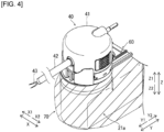
- Each surgical instrument 40 includes: a housing 41 (see FIG. 4 ) which is to be attached to the robot arm 21a; an elongate shaft 42 (see FIG. 4 ); and an end effector 43 (see FIG. 4 ) which is provided at a tip portion (a distal end portion) of the shaft 42.
- the end effector 43 may be grasping forceps, scissors, a hook, a high-frequency knife, a snare wire, a clamp, a stapler, a clip applier, an electric knife, or a needle, for example.
- the end effector 43 is not limited to those and can be various types of treatment tools.
- the robot arms 21a introduce the surgical instruments 40 into the body of the patient P through a cannula (trocar) placed on the body surface of the patient P.
- the end effectors 43 of the surgical instruments 40 are then located near a surgery site.
- the endoscope 50 as the medical equipment is detachably attached.
- the endoscope 50 captures an image in a body cavity of the patient P.
- the captured image is outputted to the remote control apparatus 10.
- the endoscope 50 may be a 3D endoscope capable of capturing a three-dimensional image or a 2D endoscope.
- the robot arm 21b introduces the endoscope 50 into the body of the patient P through a trocar placed on the body surface of the patient P. The endoscope 50 is then located near the surgery site.
- the remote control apparatus 10 constitutes an interface with the operator.
- the remote control apparatus 10 is an apparatus that allows the operator to operate the medical equipment attached to the robot arms 21a and 21b.
- the remote control apparatus 10 is configured to transmit action mode instructions which are inputted by the operator and are to be executed by the surgical instruments 40 and the endoscope 50, to the patient-side apparatus 20 through the controller 24.
- the remote control apparatus 10 is installed beside the operation table 30 so that the operator can see the condition of the patient P very well while operating the remote control apparatus 10, for example.
- the remote control apparatus 10 may be configured to transmit the action mode instructions wirelessly and installed in a room different from the operation room where the operation table 30 is installed.
- the action modes to be executed by the surgical instruments 40 include modes of actions to be taken by each surgical instrument 40 (a series of positions and postures) and actions to be executed by the function of each surgical instrument 40.
- the surgical instrument 40 is a pair of grasping forceps, for example, the action modes to be executed by the surgical instrument 40 include roll and pitch positions of the wrist of the end effector 43 and actions to open and close the jaws.
- the surgical instrument 40 is a high-frequency knife
- the action modes to be executed by the surgical instrument 40 include vibration of the high-frequency knife, specifically, supply of current to the high-frequency knife.
- the action modes to be executed by the surgical instrument 40 include a capturing action and an action to release the captured object. Further, the action modes may include an action to supply current to a bipolar or monopolar instrument to burn off the surgery site.
- the action modes to be executed by the endoscope 50 include the position and posture of the distal end of the endoscope 50 and setting of the zoom magnification, for example.
- the remote control apparatus 10 includes operation handles 11, an operation pedal section 12, a display 13, a touch panel 14, and a control apparatus 15.
- the operation handles 11 extend from the rear side of the remote control apparatus 10 toward the front side.
- the operation handles 11 are configured to move in a predetermined three-dimensional operation region.
- the operation handles 11 are configured to be movable in a vertical direction, a horizontal direction, a front-rear direction, and a rotational direction.
- the operation handles 11 are hand controllers to be operated by the hands of the operator.
- the operation handle 11 includes a support member 11a, a pair of grip members 11b provided on both sides of the support member 11a with the support member 11a being interposed between the pair of grip members 11b, and a finger insertion portion 11c provided in each of the pair of grip members 11b.
- the operator inserts fingers (such as (thumb, middle finger, etc.) into the pair of finger insertion portions 11c to operate the operation handle 11. That is, a proximal end of each of the pair of grip members 11b is rotatably connected to a support member 11a.
- an open angle between a pair of jaw members 43a and 43b By increasing or decreasing an open angle between the pair of grip members 11b (a grip open angle), an open angle between a pair of jaw members 43a and 43b, which will be described later, is changed.
- a command for opening and closing the pair of jaw members 43a and 43b is input to the operation handle 11.
- the open angle between the pair of gripping members 11b is detected by a sensor, for example.
- the operation handle 11 is provided with a hole sensor at the support member 11a and with a magnet at one or each of the pair of grip members 11b, so that the open angle between the pair of grip members 11b can be detected.
- the operation handle 11 is provided with a hole sensor at one of the pair of grip members 11b and with a magnet at the other of the pair of grip members 11b, so that the open angle between the pair of grip members 11b can be detected. Based on a signal relating to the detected open angle between the pair of grip members 11b, the pair of jaw members 43a and 43b are controlled to open and close.
- the remote control apparatus 10 and patient-side apparatus 20 constitute a master-slave system in terms of controlling movements of the robot arm 21a and the robot arms 21b.
- the operation handles 11 constitute a controlling part on the master side in the master-slave system, and the robot arms 21a and 21b holding the medical equipment constitute an acting part on the slave side.
- the movement of one of the robot arms 21a or 21b is controlled so that the distal end portion (the end effector 43 of the surgical instrument 40) of the robot arm 21a or the distal end portion (the endoscope 50) of the robot arm 21b moves following the movement of the operation handles 11.
- the patient-side apparatus 20 controls the movement of the robot arms 21a in accordance with the set motion scaling ratio.
- the motion scaling ratio is set to 1/2, for example, the end effectors 43 of the surgical instruments 40 move 1/2 of the movement distance of the operation handles 11. This allows for precise fine surgery.
- the operation pedal section 12 includes plural pedals to execute medical equipment-related functions.
- the plural pedals include a coagulation pedal, a cutting pedal, a camera pedal, and a clutch pedal.
- the plural pedals are operated by a foot of the operator.
- the coagulation pedal enables the surgical instrument 40 to coagulate a surgery site. Specifically, when the coagulation pedal is operated, voltage for coagulation is applied to the surgical instrument 40 to coagulate the surgery site.
- the cutting pedal enables the surgical instrument 40 to cut the surgery site. Specifically, the cutting pedal is operated to apply voltage for cutting to the surgical instrument 40 and cut a surgery site.
- the clutch pedal is used to temporarily disconnect operation-related connection between the robot arms 21a and the operation handles 11 to stop movement of the surgical instruments 40. Specifically, when the clutch pedal is being pressed, the robot arms 21a of the patient-side apparatus 20 do not work even if the operation handles 11 are operated. For example, when the operation handles 11 are operated and moved to the edge of the range of movement, the operator operates the clutch pedal to temporarily disconnect the operation-related connection and then returns the operation handles 11 to the center of the range of movement. When the operator stops operating the clutch pedal, the operation handles 11 are again connected to the robot arms 21a. The operator restarts the operation for the operation handles 11 around the center thereof.
- the display 13 is configured to display images captured by the endoscope 50.
- the display 13 comprises a scope type display or a non-scope type display.
- FIG. 1 illustrates a scope type display.
- the scope type display is a display configured in such a manner that the operator looks into the display.
- the non-scope type display is a display like an open-type display that includes a flat screen and the operator is able to see without looking into, such as normal displays for personal computers.
- the scope type display When the scope type display is attached, the scope type display displays 3D images captured by the endoscope 50 attached to the robot arm 21b of the patient-side apparatus 20.
- the non-scope type display When the non-scope type display is attached, the non-scope type display also displays 3D images captured by the endoscope 50 provided for the patient-side apparatus 20.
- 2D images captured by the endoscope 50 provided to the patient-side apparatus 20 may be displayed.
- the touch panel 14 serves as an operation section and a display section.
- the touch panel 14 displays a screen for setting operations for the remote control apparatus 10 and receives setting operations for the remote control apparatus 10.
- the control apparatus 15 includes a controller 151, a storage 152, and an image controller 153, for example.
- the controller 151 includes an arithmetic unit such as a CPU.
- the storage 152 includes a memory, such as a ROM and a RAM.
- the control apparatus 15 may be composed of a single controller performing centralized control or may be composed of plural controllers that perform decentralized control in cooperation with each other.
- the controller 151 determines whether an action mode instruction inputted by the operation handles 11 is to be executed by the robot arms 21a or to be executed by the endoscope 50, depending on the state of the operation pedal section 12.
- the controller 151 When determining that the action mode instruction inputted by the operation handles 11 is to be executed by any one of the surgical instruments 40, the controller 151 transmits the action mode instruction to the corresponding robot arm 21a through the controller 24.
- the robot arm 21a is thereby driven by the controller 24 and thus movement of the surgical instrument 40 attached to the robot arm 21a is controlled.
- the controller 151 When determining that the action mode instruction inputted by the operation handles 11 is to be executed by the endoscope 50, the controller 151 transmits the action mode instruction to the robot arm 21b through the controller 24. The robot arm 21b is thereby driven for control of movement of the endoscope 50 attached to the robot arm 21b.
- the storage 152 stores control programs corresponding to the types of the surgical instrument 40, for example.
- the controller 151 reads the stored control programs according to the types of the attached surgical instruments 40.
- the action mode instructions from the operation handles 11 and/or the operation pedal section 12 of the remote control apparatus 10 thereby cause the respective surgical instruments 40 to perform proper movements.
- the image controller 153 transmits images acquired by the endoscope 50 to the display 13.
- the image controller 153 performs processing and modifying the images when needed.
- the direction in which the surgical instrument 40 extends is defined as a Y direction
- the distal side (the side toward the end effector 43) of the surgical instrument 40 along the Y direction is defined as a Y1 direction
- the opposite side of the Y1 direction is defined as a Y2 direction
- the direction in which the surgical instrument 40 and the adaptor 60 are adjacent to each other is defined as a Z direction
- the surgical instrument 40 side along the Z direction is defined as a Z1 direction
- the opposite side of the Z1 direction is defined as a Z2 direction.
- the direction orthogonal to the Y direction and the Z direction is referred to as an X direction
- one side along the X direction is referred as an X1 direction
- the other side along the X direction is referred to as an X2 direction.
- the surgical instrument 40 is removably attached to the robot arm 21a.
- the surgical instrument 40 is detachably attached to the robot arm 21a via the adaptor 60.
- the adaptor 60 is a drape adaptor configured to sandwich a sterile drape 70 to cover the robot arm 21a, in conjunction with the robot arm 21a.
- the surgical instrument 40 is attached to the Z1 side of the adaptor 60.
- the adaptor 60 is attached to the Z1 side of the robot arm 21a.
- the robot arm 21a is used in a clean area and is covered with the drape 70.
- clean technique is used in order to prevent surgical incision sites and medical equipment from being contaminated by pathogen, foreign matters, or the like.
- the clean technique defines a clean area and a contaminated area, which is outside the clean area.
- the surgery sites are located in the clean area.
- Members of the surgical team, including the operator make sure that only sterile objects are placed in the clean area during surgery and perform sterilization for an object which is to be moved to the clean area from the contaminated area.
- an assistant as one of the members of the surgical team including the operator, places their hands in the contaminated area, the members sterilize their hands before directly touching objects located in the clean area. Instruments used in the clean area are sterilized or are covered with the drapes 70 that are sterilized.
- the attachment section 72 includes an opening so that the robot arm 21a is engaged with the adaptor 60.
- the opening of the attachment section 72 may be provided corresponding to the section where the robot arm 21a is engaged with the adaptor 60.
- the opening of the attachment section 72 may include plural openings corresponding to plural sections at which the robot arm 21a is engaged with the adaptor 60.
- the surgical instrument 40 includes plural (four) driven members 44a, 44b, 44c, and 44d, and a storage 45.
- the storage 45 is provided in the housing 41.
- the storage 45 stores a serial number representing the surgical instrument 40, a number of times the surgical instrument 40 has been used, and values ⁇ 1 and ⁇ 0 , which will be described later. in the embodiment, the value ⁇ 1 is set to approximately half the value ⁇ 0 .
- the storage 45 is communicatively connected to the controller 24.
- the storage 45 is an example of a first storage.
- the value ⁇ 1 is an example of a first value.
- the value ⁇ 0 is an example of a third value.
- the driven members 44a to 44d are provided within the housing 41 and are rotatable about the respective rotation axes extending along the Z axis.
- the plural driven members 44a to 44d are provided to operate (drive) the end effector 43.
- the driven members 44b to 44d are connected to the end effector 43 via cables A, serving as elongate elements, passing through the inside of the shaft 42. With this, rotations of the driven members 44b to 44d drive the cables A, which operate (drive) the end effector 43.
- the driven member 44a is connected to the shaft 42 through gears 42a (see FIG. 7 ). With this, the shaft 42 is rotated with rotation of the driven member 44a, and the end effector 43 is also rotated with rotation of the shaft 42.
- each of the driven members 44a to 44d includes a projection 441 or 442, which is engaged with a corresponding one of drive transmission members 61 of the adaptor 60.
- Each of the projections 441 and 442 is projected from the Z2 side surface of the corresponding driven member 44a to 44d toward the side of the adaptor 60 (the Z2 side).
- Each of the projections 441 and 442 includes plural projection portions that arranged in a straight line.
- the protrusions 441 provided to the driven members 44a and 44b have different shapes from that of the protrusions 442 provided to the driven members 44c and 44d.
- the adaptor 60 includes a plurality (four) of the drive transmission members 61.
- the drive transmission members 61 are configured to transmit the driving forces from the robot arm 21a to the driven members 44a to 44d of the surgical instrument 40. That is, the drive transmission members 61 are provided so as to correspond to the driven members 44a to 44d of the surgical instrument 40.
- the drive transmission members 61 are rotatable about the respective rotation axes, which extend along the Z direction.
- Each of the drive transmission members 61 includes an engagement recess 611 which is engaged with the projection 441 or 442 of the corresponding driven member 44a to 44d of the surgical instrument 40.
- the engagement recess 611 is located at the surgical instrument 40 side (the Z1 side) of the drive transmission member 61 and is recessed from the Z1 side surface of the drive transmission member 61, toward the Z2 direction, opposite to the surgical instrument 40.
- Each of the drive transmission members 61 includes an engagement recess, which is provided on the Z2 side surface thereof and is configured to be engaged with a corresponding engagement projection 213 of the robot arm 21a.
- the robot arm 21a includes a frame 211, plural (four) drive parts 212, and plural engagement projections 213.
- the plural drive parts 212 are provided corresponding to the plural (four) driven members 44a to 44d of the surgical instrument 40 and corresponding to the plural (four) drive transmission members 61 of the adaptor 60.
- the drive part 212 is configured to drive the engagement projection 213 to rotate about a rotation axis thereof extending in the Z direction.
- the engagement projection 213 is engaged with the engagement recess provided on the Z2 side surface of the drive transmission member 61.
- the engagement projection 213 is projected from the Z1 side surface of the robot arm 21a toward the Z1 side (the adaptor 60 side).
- the drive parts 212 are configured to drive the drive transmission members 61 of the adaptor 60, engaged with the engagement projections 213, to rotate about the rotational axes extending in the Z direction, so as to drive the driven members 44a to 44d of the surgical instrument 40, engaged with the drive transmission members 61, to rotate about the rotational axes extending in the Z direction.
- the configuration of the surgical instrument 40 is described in detail below.
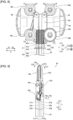
- the end effector 43 of the surgical instrument 40 is a grasping forceps including the pair of jaw members 43a and 43b.
- the surgical instrument of the invention includes at least a pair of jaw members, and the pair of jaw members may be scissors or the like, for example.
- the cables A are wound around the driven members 44b to 44d of the surgical instrument 40. That is, the cables A are connected to the driven members 44b to 44d.
- the cable A3 is wound around the driven member 44b. Specifically, a first portion A3a of the cable A3 is wound in the clockwise direction around an upper portion of the driven member 44b, and a second portion A3b of the cable A3 is wound in the counterclockwise direction around a lower portion of the driven member 44b.
- the cable A1 is wound around the driven member 44c of the surgical instrument 40. Specifically, a first portion A1a of the cable A1 is wound in the clockwise direction around an upper portion of the driven member 44c, and a second portion A1b of the cable A1 is wound in the counterclockwise direction around a lower portion of the driven member 44c.
- the cable A2 is wound around the driven member 44d. Specifically, a first portion A2a of the cable A2 is wound in the clockwise direction around an upper portion of the driven member 44d, and a second portion A2b of the cable A1 is wound in the counterclockwise direction around a lower portion of the driven member 44d.
- the cables A extend respectively from the driven members 44b to 44d through the shaft 42 to the end effector 43, are wound around the end effector 43, and return through the shaft 42 to the driven members 44b to 44d.
- the cables A are hung on pulleys 46.
- the pulleys 46 are retained by a pulley retainer 461.
- the rotation of the driven member 44c operates the jaw member 43a, which is one of the jaw members 43a and 43b of the end effector 43.
- the driven member 44c is rotated by the drive part 212 to drive the cable A1.
- the cable A1 extends through the inside of the shaft 42 and connects the jaw member 43a and the driven member 44c.
- the cable A1 is wound around a pulley 43d provided at the base of the jaw member 43a.
- the first potion A1a of the cable A1 is pulled and the second portion A1b of the cable A1 is fed, so as to drive the jaw member 43a to move in the C1a direction (see FIG. 9 ), which is a direction to open the jaw member 43a.
- the driven member 44c is rotated in the C2 direction opposite to the C1 direction (see FIG. 8 )
- the first portion A1a of the cable A1 is fed and the second portion A1b of the cable A1 is pulled, so as to drive the jaw member 43a to move in the C2a direction (see FIG. 9 ), which is a direction to close the jaw member 43a.
- the rotation of the driven member 44d operates the jaw member 43b, which is one of the jaw members 43a and 43b of the end effector 43.
- the driven member 44d is rotated by the drive part 212 to drive the cable A2.
- the cable A2 extends through the inside of the shaft 42 and connects the jaw member 43b and the driven member 44d.
- the cable A2 is wound around a pulley 43e provided at the base of the jaw member 43b.
- the first potion A2a of the cable A2 is pulled and the second portion A2b of the cable A2 is fed, so as to drive the jaw member 43b to move in the C3a direction (see FIG. 9 ), which is a direction to open the jaw member 43b.
- the driven member 44d is rotated in the C4 direction opposite to the C3 direction (see FIG. 8 )
- the first potion A2a of the cable A2 is fed and the second portion A2b of the cable A2 is pulled, so as to drive the jaw member 43b to move in the C4a direction (see FIG. 9 ), which is a direction to close the jaw member 43b.
- the jaw members 43a and 43b are opened and closed with respect to each other by the movements of the cables A of the driven members 44b and 44c.
- the cables A1 and A2 are examples of elongate elements.
- the driven member 44b By being rotated about the rotation axis thereof, the driven member 44b operates a wrist portion 43c of the end effector 43. Specifically, the driven member 44b is rotated by the drive part 212 to drive the cable A3.
- the cable A3 extends through the inside of the shaft 42 and connects the wrist portion 43c and the driven member 44b.
- the driven member 44b When the driven member 44b is rotated in the C5 direction (see FIG. 8 ), the first potion A3a of the cable A3 is pulled and the second portion A3b of the cable A3 is advanced, so as to drive the wrist portion 43c to move in the C5a direction (see FIG. 9 ).
- the driven member 44b When the driven member 44b is rotated in the C6 direction opposite to the C5 direction (see FIG.
- the second portion A3b of the cable A3 is pulled and the first potion A3a of the cable A3 is fed, so as to drive the wrist portion 43c to move in the C6a direction, which is opposite to the C5a direction (see FIG. 9 ).
- the shaft 42 is driven to operate the end effector 43.
- the driven member 44a rotates in the C7 direction (see FIG. 8 )
- the shaft 42 is driven to rotate in the C7a direction (see FIG. 9 ) and thus the end effector 43 is driven to rotate in the C7a.
- the driven member 44a rotates in the C8 direction (see FIG. 8 )
- the shaft 42 is driven to rotate in the C8a direction, which is opposite to the C7a direction (see FIG. 9 ), and thus the end effector 43 is driven to rotate in the C8a direction.
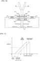
- each drive part 212 includes a motor 212a, a decelerator 212b, and a position detector 212c.
- the motor 212a is composed of a servo motor, and is a drive source that drives the cable A1 (A2) and the jaw member 43a (43b).
- the decelerator 212b reduces a rotation speed of the motor 212a and outputs the reduced rotation.
- the position detector 212c is composed of an absolute encoder and detects a rotation angle of the motor 212a.
- a current detector 214 is provided for the motor 212a. The current detector 214 detects a current value of the motor 212a.
- the controller 24 drives the motors 212a based on a signal from the operation handles 11. With this, the decelerator 212b, the engagement protrusion 213, the drive transmission member 61, and the driven members 44c, 44d are rotated, so as to drive the cables A1, A2. As a result, the jaw members 43a and 43b are opened and closed.
- the controller 24 drives the motor 212a such that the open angle between the jaw members 43a and 43b becomes an open angle that corresponds to a signal from the operation handles 11 (a target open angle).
- the controller 24 controls, based on the detection result of the rotation angle of the motor 212a detected by the position detector 212c, the rotation angle of the motor 212a such that the rotation angle corresponds to the target open angle. That is, the controller 24 controls the driving of the jaw members 43a and 43b by the rotation angle of the motor 212a.
- the decelerator 212b having the high reduction ratio is used in a case in which the motor 212a is torque-controlled, the behavior of the distal end side of the surgical instrument 40 is less likely to be reflected as a change in the torque of the motor 212a. This makes it difficult to detect the behavior of the distal end side of the surgical instrument 40 by detecting the change in the torque of the motor 212a. In order to solve this problem, it is effective to control the rotation angle of the motor 212a that drives the jaw members 43a and 43b.
- a tightening force (gripping force) can be generated by the jaw members 43a and 43b.
- a command angle by which the jaw members 43a and 43b are further closed from the state in which the open angle between the jaw members 43a and 43b is zero is referred to as a tightening angle.
- the tightening angle is a negative value, but is not limited thereto.
- the tightening angle is an example of a value corresponding to the rotation angle of the motor 212a, and is calculated by the following formula (1).
- the surgical instrument 40 is washed and sterilized after each surgery and is used multiple times. Therefore, as the surgical instrument 40 is used over time, lengths of the cables A1 and A2 that drive the jaw members 43a and 43b may become elongated. When the lengths of the cables A1, A2 become elongated, even if the motor 212a is controlled to a predetermined rotation angle, the jaw members 43a and 43b cannot be sufficiently tightened, and the gripping force of the jaw members 43a and 43b decreases.
- the controller 24 performs calibration to compensate for the elongation of the cables A1 and A2.
- the storage 45 stores in advance a tightening angle ⁇ 1 when the current value reaches a predetermined value I 1 .
- the controller 24 acquires a tightening angle ⁇ 2 when the current valure reaches the predetermined current value I 1 , and performs calibration to change the command angle for the tightening operation of the jaw members 43a and 43b based on the acquired value ⁇ 2 and the value ⁇ 1 stored in the storage 45.
- the controller 24 corrects a maximum tightening angle ⁇ 0 based on the tightening angle ⁇ 1 and the tightening angle ⁇ 2 .
- the maximum tightening angle is the tightening angle an absolute value of which is the largest.
- the maximum tightening angle ⁇ 0 is an example of a value corresponding to a maximum rotation angle of the motor 212a in the closing direction of the jaw members 43a and 43b.
- the controller 24 corrects the value ⁇ 0 based on the values ⁇ 2 and ⁇ 1 . With this, it possible to correct the maximum tightening angle ⁇ 0 between the jaw members 43a and 43b, and therefore to increase the maximum rotation angle of the motor 212a which can rotate in the closing direction of the jaw members 43a and 43b. As a result, it is possible to reliably prevent the decrease in the gripping force of the jaw members 43a and 43b caused by the elongation of the cables A1 and A2.
- the controller 24 corrects the value ⁇ 0 by adding the difference ⁇ between the value ⁇ 2 and the value ⁇ 1 to the value ⁇ 0 .
- the controller 24 performs the calibration that changes the value ⁇ 0 of the command angle to a value ⁇ 0 + ⁇ .
- the controller 24 corrects the value ⁇ 0 so that the jaw members 43a and 43b can close up to the tightening angle of ( ⁇ 0 + ⁇ ) obtained by adding the difference ⁇ between the tightening angle values ⁇ 2 and ⁇ 1 to the tightening angle value ⁇ 0 .
- This enables the jaw members 43a and 43b to be closed up to a tightening angle obtained by adding the difference ⁇ between the tightening angle values ⁇ 2 and ⁇ 1 to the tightening angle value ⁇ 0 (i.e., the maximum tightening angle ⁇ 0 + ⁇ taking into account the elongation of the cables A1, A2). Therefore, it is possible to more reliably suppress a decrease in the gripping force of the jaw members 43a and 43b caused by the elongation of the cables A1, A2 over time.
- the storage 45 stores in advance, as initial values, the tightening angle value ⁇ 1 when the current value reaches the predetermined value I 1 , and a maximum tightening angle ⁇ 0 .
- the values ⁇ 1 and ⁇ 0 are stored in advance in the storage 45 by an operator at the manufacturer before the surgical instrument 40 is shipped from the manufacturer. At the manufacturer, the values ⁇ 1 and ⁇ 0 are obtained taking into account the initial slack of the cables A1 and A2.
- the value ⁇ 0 is set to a value that enables the jaw members 43a and 43b to exert a predetermined gripping force.
- the absolute value of the value ⁇ 0 is greater than the absolute value of the value ⁇ 1 .
- the controller 24 starts the calibration from a state in which the jaw members 43a and 43b are closed (a state in which the open angle between the jaw members 43a and 43b is zero).
- the controller 24 drives the motor 212a to rotate to make the tightening angle the maximum tightening angle ⁇ 0 .
- the controller 24 acquires the value ⁇ 2 .
- the jaw members 43a and 43b are further closed from the state the jaw members 43a and 43b are closed, the current value of the motor 212a increases.
- the current value of the motor 212a is detected (monitored) by the current detector 214. in the case in which the cables A1, A2 are streached, even when the tightening angle of the jaw members 43a and 43b reaches the value ⁇ 1 , the current value of the motor 212a reaches a value smaller than the predetermined current value I 1 .
- the controller 24 obtains the tightening angle value ⁇ 2 when the current value of the motor 212a reaches the predetermined current value I 1 based on the detection result of the current detector 214. In addition, the controller 24 calculates the difference ⁇ between the value ⁇ 2 and the value ⁇ 1 .
- the difference ⁇ between the value ⁇ 2 and the value ⁇ 1 corresponds to the elongation of the cables A1 and A2 due to use. Further, the controller 24 corrects the value ⁇ 0 so that the jaw members 43a and 43b are able to be closed up to a tightening angle ⁇ 0 + ⁇ obtained by adding the difference ⁇ between the values ⁇ 2 and ⁇ 1 to the initial maximum tightening angle value ⁇ 0 .
- This can make the current response of the motor 212a in the state in which the cables A1 and A2 are elongated equivalent to the initial current response of the motor 212a, thereby suppressing a decrease in the gripping force of the jaw members 43a and 43b caused by the elongation of the cables A1 and A2.
- the absolute value of the value ⁇ 0 is greater than the absolute value of the value ⁇ 2 .
- the controller 24 determines, based on the threshold value ⁇ S1 , whether or not the value ⁇ 2 is within a predetermined range with respect to the value ⁇ 1 . when it is determined that the value ⁇ 2 is within the predetermined range with respect to the value ⁇ 1 , the controller 24 does not correct the value ⁇ 0 . To the contrary, when it is determined that the value ⁇ 2 is out of the predetermined range with respect to the value ⁇ 1 , the controller 24 corrects the value ⁇ 0 .
- the controller 24 determines whether the value ⁇ 2 is within the range ⁇ 1 ⁇ ⁇ S1 .
- the threshold value ⁇ S1 is not particularly limited, and may be a value obtained by converting a value (such as Y Newtons) that determines the upper and lower limits of the range (such as X ⁇ Y Newtons) of the set gripping force of the jaw members 43a and 43b into a tightening angle using a conversion coefficient. Note that when the range of the set gripping force differs depending on the type of the jaw members 43a and 43b (i.e., the type of the end effector 43), the threshold value ⁇ S1 may be different for each type of the end effector 43.
- the threshold value ⁇ S1 is a positive value in the embodiment, and is stored in the storage 25 provided in the robot body 27.
- the controller 24 determines whether the difference ⁇ between the value ⁇ 2 and the value ⁇ 1 is within the normal range based on the threshold value ⁇ S2 . When it is determined that the difference ⁇ between the value ⁇ 2 and the value ⁇ 1 is within the normal range, the controller 24 corrects the value ⁇ 0 . To the contrary, when it is determined that the difference ⁇ between the value ⁇ 2 and the value ⁇ 1 is outside the normal range, the controller 24 reacquires the value ⁇ 2 . As a result, when it is determined that the difference ⁇ between the value ⁇ 2 and the value ⁇ 1 is within the normal range, the value ⁇ 0 is corrected so that the calibration can be performed appropriately.
- the storage 45 that stores the value ⁇ 1 is provided in the surgical instrument 40. This allows a different value ⁇ 1 for each surgical instrument 40 to be stored in advance in the storage 45 provided in the surgical instrument 40, so that an appropriate value ⁇ 1 for each surgical instrument 40 can be easily used when using the surgical instrument 40.
- the storage 45 also stores the value ⁇ 0 . As in the value ⁇ 1 , this allows a different value ⁇ 0 for each surgical instrument 40 to be stored in advance in the storage 45 provided in the surgical instrument 40, so that an appropriate value ⁇ 0 for each surgical instrument 40 can be easily used when using the surgical instrument 40.
- the temporary storage 26 that stores a correction value ( ⁇ ) based on the value ⁇ 1 and the value ⁇ 2 is provided in the robot body 27.
- the temporary storage 26 that stores a correction value ( ⁇ ) based on the value ⁇ 1 and the value ⁇ 2 is provided in the robot body 27.
- the controller 24 starts the calibration at least one of the following times: when the surgical instrument 40 is attached to the robot arm 21a; and when a user interface (such as the operation handle 11 or the touch panel 14) that accepts an operation to execute the calibration is operated.
- a user interface such as the operation handle 11 or the touch panel 14
- the calibration is executed simply by attaching the surgical instrument 40 to the robot arm 21a, thereby saving the user effort.
- the calibration is executed at a timing desired by the user.
- the operation handle 11 or the touch panel 14 is an example of a user interface.
- the controller 24 determines whether or not the surgical instrument 40 is attached to the robot arm 21a for the first time during the surgery. When it is determined that the attachment of the surgical instrument 40 to the robot arm 21a is for the first time during the surgery, the controller 24 starts the calibration, and when it is determined that the attachment of the surgical instrument 40 to the robot arm 21a is not for the first time during the surgery, the controller 24 does not start the calibration. This allows the calibration to be started appropriately when it is determined that the surgical instrument 40 is attached to the robot arm 21a for the first time during the surgery (i.e., when the calibration has not been performed). Further, when it is determined that the attachment of the surgical instrument 40 to the robot arm 21a is not the first time during the surgery (i.e., when the calibration has already been performed), the calibration is not started, thereby preventing unnecessary calibration from being performed.
- the controller 24 obtains the serial number of the surgical instrument 40 from the storage 45, and determines based on the obtained serial number of the surgical instrument 40 whether or not this is the first time that the surgical instrument 40 has been attached to the robot arm 21a during the surgery. Specifically, when the obtained serial number of the surgical instrument 40 is not stored in the storage 25 or the temporary storage 26, the controller 24 determines that this is the first time that the surgical instrument 40 has been attached to the robot arm 21a during the surgery. In addition, the controller 24 stores the obtained serial number of the surgical instrument 40 in the storage 25 or the temporary storage 26.
- the controller 24 determines that this is not the first time that the surgical instrument 40 has been attached to the robot arm 21a during the surgery (that is, this is the second or subsequent time).
- the controller 24 determines that it is not the first time that the surgical instrument 40 is attached to the robot arm 21a during the surgery, the controller 24 does not start calibration and corrects ⁇ 0 using the correction value ( ⁇ ) at the time of the initial attachment.
- the controller 24 corrects the value ⁇ 0 based on the value ⁇ 2 , the value ⁇ 1 , and the value ⁇ a corresponding to the rotation angle of the motor 212a that is determined in advance according to the number of times the surgical instrument 40 is used.
- This allows the value ⁇ 0 to be corrected not only based on the values ⁇ 2 and ⁇ 1 but also on the tightening angle ⁇ a that is determined in advance according to the number of times the surgical instrument 40 is used, thereby more reliably suppressing the decrease in the gripping force of the jaw members 43a and 43b caused by the elongation of the cables A1 and A2.
- the value ⁇ a is a fixed value determined according to the number of times the surgical instrument 40 is used, and is obtained in advance by experiment or the like.
- the value ⁇ a is an example of a fourth value.
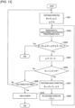
- step S101 the surgical instrument 40 is attached to the robot arm 21a via the adapter 60.
- step S102 a matting operation mode is started.
- the engagement projections 213 of the robot arm 21a are mated with the engagement recesses of the drive transmission members 61 of the adapter 60
- the engagement recesses 611 of the drive transmission members 61 of the adapter 60 are mated with the projections 441 and 442 of the driven members 44a to 44d.
- step S103 it is determined whether or not the surgical instrument 40 is attached to the robot arm 21a for the first time during surgery.
- the process proceeds to step S104.
- step S104 a calibration mode in which calibration is performed is started.
- step S106 the process proceeds to step S106.
- the calibration mode process will be described in detail later.
- step S106 a gripping force check mode is started.
- the gripping force check mode it is determined whether or not the predetermined gripping force can be output as the gripping force by the jaw members 43a and 43b. Then, when it is determined that the predetermined gripping force can be output as the gripping force by the jaw members 43a and 43b, the control process is terminated.
- step S201 a tightening operation of the jaw members 43a and 43b is performed.
- step S202 the rotation angle of the motor 212a when the current value reaches the predetermined value I 1 is obtained.
- the current value of the motor 212a is obtained taking into consideration the friction and inertia of the motor 212a.
- the rotation angle of the motor 212a that is detected by the position detector 212c when the current value reaches the predetermined value I 1 is converted into the tightening angle of the jaw members 43a and 43b by the above described formula (1), thereby obtaining the tightening angle value ⁇ 2 .
- ⁇ 0 stored in advance in the storage 45 is used as the maximum tightening angle.
- step S203 when it is determined in step S203 for the first time that the value ⁇ 2 is not within the predetermined range with respect to the value ⁇ 1 , it means that it is determined that the elongation of the cables A1 and A2 is large and the correction is necessary, and the process proceeds to step S204.
- step S205 it is determined based on the threshold value ⁇ S2 whether or not the difference ⁇ is within the normal range. Specifically, it is determined whether the difference ⁇ is within the range of ⁇ S2 ⁇ ⁇ ⁇ 0. When it is determined that the difference ⁇ is within the normal range, the process proceeds to step S207.
- step S207 the tightening angle correction is performed to correct the value ⁇ 0 based on the values ⁇ 1 and ⁇ 2 .
- the value ⁇ 0 is corrected by adding the difference ⁇ between the value ⁇ 1 and the value ⁇ 2 to the value ⁇ 0 .
- step S208 a re-tightening operation is performed that closes the jaw members 43a and 43b again.
- the jaw members 43a and 43b are driven to close up to the corrected maximum tightening angle ⁇ 0c .
- the process proceeds to step S202.
- step S202 the tightening angle ⁇ 2 at which the current value becomes the predetermined value I 1 is obtained again.
- ( ⁇ 2 - ⁇ ) is ( ⁇ 2 - ⁇ 2 + ⁇ 1 ), which is ⁇ 1 . Therefore, in step S203, it is determined that ⁇ 2 - ⁇ is within the range of ⁇ 1 - ⁇ S1 ⁇ ⁇ 2 - ⁇ ⁇ ⁇ 1 + ⁇ S1 , and the control process is terminated with the correction being performed.
- step S205 When it is determined in step S205 that the difference ⁇ is not within the normal range, the process proceeds to step S209.
- step S209 it is determined whether the difference ⁇ is determined to be outside the normal range for two consecutive times.
- the process proceeds to step S201.
- the processes of step S201 to step S205 are repeated.
- step S210 an error message is displayed and the control process is terminated.
- the values corresponding to the rotation angles of the motor are values that represent the tightening angles between the jaw members, but the invention is not limited to this.
- the value corresponding to the rotation angle of the motor may represent a value other than the tightening angle between the jaw members.
- the value corresponding to the rotation angle of the motor may be the rotation angle of the motor.
- the third value ( ⁇ 0 ) is a value that corresponds to the maximum rotation angle of the motor in the closing direction of the jaw members, but the invention is not limited to this.
- the third value may be a value having an absolute value greater than the value ⁇ 1 and corresponding to a rotation angle other than the maximum rotation angle of the motor in the closing direction of the jaw members.
- the first storage (45) that stores the first value ( ⁇ 1 ) and the third value ( ⁇ 0 ) is provided in the surgical instrument
- the second storage (26) that stores the correction value ( ⁇ ) based on the first value and the second value ( ⁇ 2 ) is provided in the robot body
- the first storage may be provided in the robot body
- the second storage may be provided in the surgical instrument.
- the second storage does not have to be a temporary storage.
- the calibration may be started every time the surgical instrument is attached to the robot arm.
- the fourth value ( ⁇ a ) may not be used to correct the third value ( ⁇ 0 ).
- a rod may be used as an elongate element, and a gear, a pulley, or a bearing may be used as a driven member, and the decrease in the gripping force of the jaw members caused by wear, seizure, galling, chipping, rust, etc., of the gear, pulley, bearing, and rod of the surgical instrument may be corrected. Further, in the invention, the decrease in the gripping force due to wear of the jaw members may be corrected.
- FIG. 15 illustrates another modified example using the difference ⁇ 2 .
- the value ⁇ 0 and the difference ⁇ 2 between the values ⁇ 1 and ⁇ 0 are stored in advance in the storage 45.
- the controller 24 acquires the value ⁇ 2 in the course of rotating the motor 212a to close the jaw members 43a and 43b to the point where the value corresponding to the rotation angle of the motor 212a becomes the value ⁇ 0 (the value ⁇ 0 is the target value).
- the controller 24 adds the difference ⁇ 2 to the value ⁇ 2 .
- the controller 24 performs the calibration that changes the command angle value ⁇ 0 to the value ⁇ 2 + ⁇ 2 .
Landscapes
- Health & Medical Sciences (AREA)
- Engineering & Computer Science (AREA)
- Life Sciences & Earth Sciences (AREA)
- Surgery (AREA)
- Robotics (AREA)
- Medical Informatics (AREA)
- Biomedical Technology (AREA)
- Heart & Thoracic Surgery (AREA)
- Nuclear Medicine, Radiotherapy & Molecular Imaging (AREA)
- Molecular Biology (AREA)
- Animal Behavior & Ethology (AREA)
- General Health & Medical Sciences (AREA)
- Public Health (AREA)
- Veterinary Medicine (AREA)
- Mechanical Engineering (AREA)
- Manipulator (AREA)
Abstract
Description
- The invention relates to a robotic surgical system and a method of controlling a robotic surgical system, and more particularly to a robotic surgical system and a method of controlling a robotic surgical system in which a drive of a pair of jaw members is controlled based on a rotation angle of a motor.
- Conventionally, a robotic surgical system is known that includes a surgical instrument including a pair of jaw members that are opened and closed by cables. Such a robotic surgical system is disclosed in
U.S. Patent No. 9,014,856 - The above-mentioned
U.S. Patent No. 9,014,856 - PATENT DOCUMENT 1:
U.S. Patent No. 9,014,856 - In the robotic surgical system described in the above listed
U.S. Pat. No. 9,014,856 U.S. Patent No. 9,014,856 - The invention provides a robotic surgical system and a method of controlling a robotic surgical system that are capable of suppressing a decrease in a gripping force of jaw members in a configuration in which a drive of the jaw members of a surgical instrument is controlled based on a rotation angle of a motor.
- A robotic surgical system according to a first aspect of the invention includes a surgical instrument including a pair of jaw members configured to be opened and closed by an elongate element; a robotic arm which includes a motor configured to drive the elongate element and to which the surgical instrument is attached; a first storage that stores in advance a first value corresponding to a rotation angle of the motor when a predetermined current value is reached; and a control unit that is configured to acquire a second value corresponding to the rotation angle of the motor when the predetermined current value is reached, and perform calibration to change, based on the acquired second value and the first value stored in the first storage, a command angle for a tightening operation of the jaw members.
- In the robotic surgical system according to the first aspect of the invention, as described above, the control unit is provided that acquires the second value corresponding to the rotation angle of the motor when the predetermined current value is reached, and performs the calibration to change the command angle for the tightening operation of the jaw members based on the acquired second value and the first value stored in the first storage. Accordingly, in a configuration in which the drive of the jaw members of the surgical instrument is controlled according to the rotation angle of the motor, it is possible to perform the calibration to compensate for the streatch of the elongate element. Therefore, in the configuration in which the drive of the jaw members of the surgical instrument is controlled according to the rotation angle of the motor, the decrease in the gripping force of the jaw members can be suppressed.
- A method of controlling a robotic surgical system according to a second aspect of the invention is the method of controlling the robotic surgical system which includes: a surgical instrument including a pair of jaw members configured to be opened and closed by an elongate element; and a robotic arm which includes a motor configured to drive the elongate element and to which the surgical instrument is attached. The method includes: a step of acquiring a second value corresponding to a rotation angle of the motor when a predetermined current value is reached, the second value corresponding to a first value corresponding to the rotation angle of the motor when the predetermined current value is reached; and a step of performing calibration that changes, based on the acquired second value and the first value stored in advance, a command angle for a tightening operation of the jaw members.
- In the method of controlling the robotic surgical system according to the second aspect of the invention, as described above, the method includes: the step of acquiring the second value corresponding to the rotation angle of the motor when the predetermined current value is reached, the second value corresponding to the first value corresponding to the rotation angle of the motor when the predetermined current value is reached; and the step of performing calibration that changes, based on the acquired second value and the first value stored in advance, the command angle for the tightening operation of the jaw members. Accordingly, in a configuration in which the drive of the jaw members of the surgical instrument is controlled according to the rotation angle of the motor, it is possible to perform the calibration to compensate for the streatch of the elongate element. Therefore, it is possible to provide the method of controlling the robotic surgical system that is capable of suppressing the decrease in the gripping force of the jaw members in the configuration in which the drive of the jaw members of the surgical instrument is controlled according to the rotation angle of the motor.
- According to the invention, it is possible to provide a robotic surgical system and a method of controlling a robotic surgical system that are capable of suppressing a decrease in a gripping force of jaw members in a configuration in which a drive of the jaw members of a surgical instrument is controlled based on a rotation angle of a motor.
-
-
FIG. 1 is a diagram illustrating a configuration of a robotic surgical system according to an embodiment. -
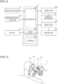
FIG. 2 is a block diagram illustrating a view of a control-related configuration of the robotic surgical system according to an embodiment. -
FIG. 3 is a diagram illustrating a view of a configuration of an operation handle according to an embodiment. -
FIG. 4 is a diagram illustrating a perspective view of a state where a surgical instrument is attached via an adapotor to a robot arm according to an embodiment. -
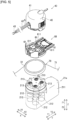
FIG. 5 is a diagram illustrating an exploded perspective view of a state where the surgical instrument is attached via the adaptor to to the robot arm according to an embodiment. -
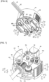
FIG. 6 is a diagram illustrating a perspective view of the surgical instrument according to an embodiment as seen from below. -
FIG. 7 is a diagram illustrating a perspective view of a state where a cover part is detached from a base body of the surgical instrument according to an embodiment. -
FIG. 8 is a diagram illustrating a plan view of a state where the cover part is detached from the base body of the surgical instrument according to an embodiment. -
FIG. 9 is a diagram illustrating a perspective view of an end effector of the surgical instrument according to an embodiment. -
FIG. 10 is a diagram illustrating a pair of jaw members, a motor, a decelerator, a current detector, a position detector, and a controller according to an embodiment. -
FIG. 11 is a graph for explaining calibration according to an embodiment. -
FIG. 12 is a flowchart illustrating a control process when the surgical instrument is attached to the robot arm according to an embodiment. -
FIG. 13 is a flowchart for explaining a control process in a calibration mode according to an embodiment. -
FIG. 14 is a graph for explaining calibration according to a modified example. -
FIG. 15 is a graph for explaining calibration according to a modification of the example illustrated inFIG. 14 . - Descriptions are provided hereinbelow for one or more embodiments based on the drawings.
- Descriptions are provided hereinbelow for an embodiment that embodies the invention based on the drawings.
- A configuration of a robotic
surgical system 100 according to an embodiment is described with reference toFIGS. 1 and2 . - As illustrated in
FIG. 1 , the roboticsurgical system 100 includes aremote control apparatus 10 which is an operator-side device, and a patient-side apparatus 20 which is a surgery assist robot. Theremote control apparatus 10 is provided to remotely control medical equipment provided to the patient-side apparatus 20. When an operator, as a surgeon, inputs an action mode instruction to be executed by the patient-side apparatus 20, to theremote control apparatus 10, theremote control apparatus 10 transmits the action mode instruction to the patient-side apparatus 20 through acontroller 24. In response to the action mode instruction transmitted from theremote control apparatus 10, the patient-side apparatus 20 operates the medical equipment, includingsurgical instruments 40 attached torobot arms 21a and anendoscope 50 attached to arobot arm 21b. This allows minimally invasive surgery. Note that thecontroller 24 is an example of a control unit. - The patient-
side apparatus 20 constitutes an interface to perform a surgery for a patient P. The patient-side apparatus 20 is positioned beside an operation table 30 on which the patient P is laid. The patient-side apparatus 20 includes the plurality ofrobot arms arm base 22, apositioner 23, thecontroller 24, astorage 25, and atemporary storage 26. Anendoscope 50 is attached to onerobot arm 21b among theplural robot arms surgical instruments 40 are attached to theother robot arms 21a. Therobot arms arm base 22. Each of theplural robot arms robot arms robot arms controller 24 and performs a desired movement. - The
arm base 22 is supported by apositioner 23 placed on the floor of an operation room. Thepositioner 23 includes a vertical articulated robot. Thepositioner 23 is configured to move the position of thearm base 22 threedimensionally. Thecontroller 24 is a control circuit including an arithmetic unit such as a CPU and/or the like, and a memory such as a ROM, a RAM, and/or the like. Thestorage 25 is a data storage, and stores a threshold value θS1 which will be described later and a threshold value θs2 which will be described later. Thetemporary storage 26 stores a difference Δθ, which will be described later. Thestorage 25 and thetemporary storage 26 are provided in arobot body 27 on which therobot arms temporary storage 26 is an example of a second storage. The threshold value θS1 is an example of a second threshold value. The threshold value θS2 is an example of a first threshold value. - The
surgical instruments 40 as the medical equipment are detachably attached to the distal ends of therobot arms 21a. Eachsurgical instrument 40 includes: a housing 41 (seeFIG. 4 ) which is to be attached to therobot arm 21a; an elongate shaft 42 (seeFIG. 4 ); and an end effector 43 (seeFIG. 4 ) which is provided at a tip portion (a distal end portion) of theshaft 42. Theend effector 43 may be grasping forceps, scissors, a hook, a high-frequency knife, a snare wire, a clamp, a stapler, a clip applier, an electric knife, or a needle, for example. Theend effector 43 is not limited to those and can be various types of treatment tools. In surgeries using the patient-side apparatus 20, therobot arms 21a introduce thesurgical instruments 40 into the body of the patient P through a cannula (trocar) placed on the body surface of the patient P. Theend effectors 43 of thesurgical instruments 40 are then located near a surgery site. - To the distal end of the
robot arm 21b, theendoscope 50 as the medical equipment is detachably attached. Theendoscope 50 captures an image in a body cavity of the patient P. The captured image is outputted to theremote control apparatus 10. Theendoscope 50 may be a 3D endoscope capable of capturing a three-dimensional image or a 2D endoscope. In surgeries using the patient-side apparatus 20, therobot arm 21b introduces theendoscope 50 into the body of the patient P through a trocar placed on the body surface of the patient P. Theendoscope 50 is then located near the surgery site. - The
remote control apparatus 10 constitutes an interface with the operator. Theremote control apparatus 10 is an apparatus that allows the operator to operate the medical equipment attached to therobot arms remote control apparatus 10 is configured to transmit action mode instructions which are inputted by the operator and are to be executed by thesurgical instruments 40 and theendoscope 50, to the patient-side apparatus 20 through thecontroller 24. Theremote control apparatus 10 is installed beside the operation table 30 so that the operator can see the condition of the patient P very well while operating theremote control apparatus 10, for example. Theremote control apparatus 10 may be configured to transmit the action mode instructions wirelessly and installed in a room different from the operation room where the operation table 30 is installed. - The action modes to be executed by the
surgical instruments 40 include modes of actions to be taken by each surgical instrument 40 (a series of positions and postures) and actions to be executed by the function of eachsurgical instrument 40. When thesurgical instrument 40 is a pair of grasping forceps, for example, the action modes to be executed by thesurgical instrument 40 include roll and pitch positions of the wrist of theend effector 43 and actions to open and close the jaws. When thesurgical instrument 40 is a high-frequency knife, the action modes to be executed by thesurgical instrument 40 include vibration of the high-frequency knife, specifically, supply of current to the high-frequency knife. When thesurgical instrument 40 is a snare wire, the action modes to be executed by thesurgical instrument 40 include a capturing action and an action to release the captured object. Further, the action modes may include an action to supply current to a bipolar or monopolar instrument to burn off the surgery site. - The action modes to be executed by the
endoscope 50 include the position and posture of the distal end of theendoscope 50 and setting of the zoom magnification, for example. - As illustrated in
FIGS. 1 and2 , theremote control apparatus 10 includes operation handles 11, anoperation pedal section 12, adisplay 13, atouch panel 14, and acontrol apparatus 15. - The operation handles 11 are provided in order to remotely operate the medical equipment attached to the
robot arms surgical instruments 40 and endoscope 50). The operation handles 11 are composed of two operation handles 11 arranged side by side in the horizontal direction. One of the two operation handles 11 is operated by the right hand of the operator while the other of the two operation handle 11 is operated by the left hand of the operator. - The operation handles 11 extend from the rear side of the
remote control apparatus 10 toward the front side. The operation handles 11 are configured to move in a predetermined three-dimensional operation region. Specifically, the operation handles 11 are configured to be movable in a vertical direction, a horizontal direction, a front-rear direction, and a rotational direction. - As illustrated in
FIG. 3 , the operation handles 11 are hand controllers to be operated by the hands of the operator. The operation handle 11 includes asupport member 11a, a pair ofgrip members 11b provided on both sides of thesupport member 11a with thesupport member 11a being interposed between the pair ofgrip members 11b, and afinger insertion portion 11c provided in each of the pair ofgrip members 11b. The operator inserts fingers (such as (thumb, middle finger, etc.) into the pair offinger insertion portions 11c to operate theoperation handle 11. That is, a proximal end of each of the pair ofgrip members 11b is rotatably connected to asupport member 11a. By increasing or decreasing an open angle between the pair ofgrip members 11b (a grip open angle), an open angle between a pair ofjaw members jaw members operation handle 11. The open angle between the pair of grippingmembers 11b is detected by a sensor, for example. For example, the operation handle 11 is provided with a hole sensor at thesupport member 11a and with a magnet at one or each of the pair ofgrip members 11b, so that the open angle between the pair ofgrip members 11b can be detected. Alternatively, the operation handle 11 is provided with a hole sensor at one of the pair ofgrip members 11b and with a magnet at the other of the pair ofgrip members 11b, so that the open angle between the pair ofgrip members 11b can be detected. Based on a signal relating to the detected open angle between the pair ofgrip members 11b, the pair ofjaw members - As illustrated in
FIG. 1 , theremote control apparatus 10 and patient-side apparatus 20 constitute a master-slave system in terms of controlling movements of therobot arm 21a and therobot arms 21b. The operation handles 11 constitute a controlling part on the master side in the master-slave system, and therobot arms robot arms end effector 43 of the surgical instrument 40) of therobot arm 21a or the distal end portion (the endoscope 50) of therobot arm 21b moves following the movement of the operation handles 11. - The patient-
side apparatus 20 controls the movement of therobot arms 21a in accordance with the set motion scaling ratio. When the motion scaling ratio is set to 1/2, for example, theend effectors 43 of thesurgical instruments 40 move 1/2 of the movement distance of the operation handles 11. This allows for precise fine surgery. - The
operation pedal section 12 includes plural pedals to execute medical equipment-related functions. The plural pedals include a coagulation pedal, a cutting pedal, a camera pedal, and a clutch pedal. The plural pedals are operated by a foot of the operator. - The coagulation pedal enables the
surgical instrument 40 to coagulate a surgery site. Specifically, when the coagulation pedal is operated, voltage for coagulation is applied to thesurgical instrument 40 to coagulate the surgery site. The cutting pedal enables thesurgical instrument 40 to cut the surgery site. Specifically, the cutting pedal is operated to apply voltage for cutting to thesurgical instrument 40 and cut a surgery site. - The camera pedal is used to control the position and orientation of the
endoscope 50 that captures images within the body cavity. Specifically, the camera pedal enables operation of theendoscope 50 by the operation handles 11. That is, the position and orientation of theendoscope 50 are controllable by the operation handles 11 while the camera pedal is being pressed. Theendoscope 50 is controlled by using both of the right and left operation handles 11, for example. Specifically, when the operator rotates the right and left operation handles 11 about the middle point between the right and left operation handles 11, theendoscope 50 is rotated. When the operator presses the right and left operation handles 11 together, theendoscope 50 goes forward into the body cavity. When the operator pulls the right and left operation handles 11 together, theendoscope 50 goes back. When the operator moves the right and left operation handles 11 together up, down, right, or left, theendoscope 50 moves up, down, right, or left, respectively. - The clutch pedal is used to temporarily disconnect operation-related connection between the
robot arms 21a and the operation handles 11 to stop movement of thesurgical instruments 40. Specifically, when the clutch pedal is being pressed, therobot arms 21a of the patient-side apparatus 20 do not work even if the operation handles 11 are operated. For example, when the operation handles 11 are operated and moved to the edge of the range of movement, the operator operates the clutch pedal to temporarily disconnect the operation-related connection and then returns the operation handles 11 to the center of the range of movement. When the operator stops operating the clutch pedal, the operation handles 11 are again connected to therobot arms 21a. The operator restarts the operation for the operation handles 11 around the center thereof. - The
display 13 is configured to display images captured by theendoscope 50. Thedisplay 13 comprises a scope type display or a non-scope type display. (Note thatFIG. 1 illustrates a scope type display.) The scope type display is a display configured in such a manner that the operator looks into the display. The non-scope type display is a display like an open-type display that includes a flat screen and the operator is able to see without looking into, such as normal displays for personal computers. - When the scope type display is attached, the scope type display displays 3D images captured by the
endoscope 50 attached to therobot arm 21b of the patient-side apparatus 20. When the non-scope type display is attached, the non-scope type display also displays 3D images captured by theendoscope 50 provided for the patient-side apparatus 20. Here, when the non-scope type display is attached, 2D images captured by theendoscope 50 provided to the patient-side apparatus 20 may be displayed. - The
touch panel 14 serves as an operation section and a display section. Thetouch panel 14 displays a screen for setting operations for theremote control apparatus 10 and receives setting operations for theremote control apparatus 10. - As illustrated in
FIG. 2 , thecontrol apparatus 15 includes acontroller 151, astorage 152, and animage controller 153, for example. Thecontroller 151 includes an arithmetic unit such as a CPU. Thestorage 152 includes a memory, such as a ROM and a RAM. Thecontrol apparatus 15 may be composed of a single controller performing centralized control or may be composed of plural controllers that perform decentralized control in cooperation with each other. Thecontroller 151 determines whether an action mode instruction inputted by the operation handles 11 is to be executed by therobot arms 21a or to be executed by theendoscope 50, depending on the state of theoperation pedal section 12. When determining that the action mode instruction inputted by the operation handles 11 is to be executed by any one of thesurgical instruments 40, thecontroller 151 transmits the action mode instruction to thecorresponding robot arm 21a through thecontroller 24. Therobot arm 21a is thereby driven by thecontroller 24 and thus movement of thesurgical instrument 40 attached to therobot arm 21a is controlled. - When determining that the action mode instruction inputted by the operation handles 11 is to be executed by the
endoscope 50, thecontroller 151 transmits the action mode instruction to therobot arm 21b through thecontroller 24. Therobot arm 21b is thereby driven for control of movement of theendoscope 50 attached to therobot arm 21b. - The
storage 152 stores control programs corresponding to the types of thesurgical instrument 40, for example. Thecontroller 151 reads the stored control programs according to the types of the attachedsurgical instruments 40. The action mode instructions from the operation handles 11 and/or theoperation pedal section 12 of theremote control apparatus 10 thereby cause the respectivesurgical instruments 40 to perform proper movements. - The
image controller 153 transmits images acquired by theendoscope 50 to thedisplay 13. Theimage controller 153 performs processing and modifying the images when needed. - With reference to
FIGS. 4 to 6 , the configurations of thesurgical instrument 40, anadaptor 60, adrape 70, and therobot arm 21a are described. - Here, the direction in which the
surgical instrument 40 extends (the direction in which theshaft 42 extends) is defined as a Y direction, the distal side (the side toward the end effector 43) of thesurgical instrument 40 along the Y direction is defined as a Y1 direction, and the opposite side of the Y1 direction is defined as a Y2 direction. The direction in which thesurgical instrument 40 and theadaptor 60 are adjacent to each other is defined as a Z direction, thesurgical instrument 40 side along the Z direction is defined as a Z1 direction, and the opposite side of the Z1 direction is defined as a Z2 direction. Further, the direction orthogonal to the Y direction and the Z direction is referred to as an X direction, one side along the X direction is referred as an X1 direction, and the other side along the X direction is referred to as an X2 direction. - As illustrated in
FIGS. 4 and5 , thesurgical instrument 40 is removably attached to therobot arm 21a. Specifically, thesurgical instrument 40 is detachably attached to therobot arm 21a via theadaptor 60. Theadaptor 60 is a drape adaptor configured to sandwich asterile drape 70 to cover therobot arm 21a, in conjunction with therobot arm 21a. - The
surgical instrument 40 is attached to the Z1 side of theadaptor 60. Theadaptor 60 is attached to the Z1 side of therobot arm 21a. - The
robot arm 21a is used in a clean area and is covered with thedrape 70. In operation rooms, clean technique is used in order to prevent surgical incision sites and medical equipment from being contaminated by pathogen, foreign matters, or the like. The clean technique defines a clean area and a contaminated area, which is outside the clean area. The surgery sites are located in the clean area. Members of the surgical team, including the operator, make sure that only sterile objects are placed in the clean area during surgery and perform sterilization for an object which is to be moved to the clean area from the contaminated area. Similarly, when an assistant, as one of the members of the surgical team including the operator, places their hands in the contaminated area, the members sterilize their hands before directly touching objects located in the clean area. Instruments used in the clean area are sterilized or are covered with thedrapes 70 that are sterilized. - As illustrated in
FIG. 5 , thedrape 70 includes abody section 71 that covers therobot arm 21a and anattachment section 72 sandwiched between therobot arm 21a and theadaptor 60. Thebody section 71 is made of a flexible film member that is formed in a film-shape. The flexible film member is made of a resin material, such as thermoplastic polyurethane and polyethylene. Thebody section 71 includes an opening so that therobot arm 21a is engaged with theadaptor 60. To the opening of thebody section 71, theattachment section 72 is provided. Theattachment section 72 is made of a resin mold member. The resin mold member is made of a resin member such as polyethylene terephthalate. Theattachment section 72 is harder (less flexible) than thebody section 71. Theattachment section 72 includes an opening so that therobot arm 21a is engaged with theadaptor 60. The opening of theattachment section 72 may be provided corresponding to the section where therobot arm 21a is engaged with theadaptor 60. The opening of theattachment section 72 may include plural openings corresponding to plural sections at which therobot arm 21a is engaged with theadaptor 60. - As illustrated in
FIGS. 5 and6 , thesurgical instrument 40 includes plural (four) drivenmembers storage 45. Thestorage 45 is provided in thehousing 41. Thestorage 45 stores a serial number representing thesurgical instrument 40, a number of times thesurgical instrument 40 has been used, and values θ1 and θ0, which will be described later. in the embodiment, the value θ1 is set to approximately half the value θ0. When thesurgical instrument 40 is attached to therobot arm 21a, thestorage 45 is communicatively connected to thecontroller 24. Note that thestorage 45 is an example of a first storage. The value θ1 is an example of a first value. The value θ0 is an example of a third value. - The driven
members 44a to 44d are provided within thehousing 41 and are rotatable about the respective rotation axes extending along the Z axis. The plural drivenmembers 44a to 44d are provided to operate (drive) theend effector 43. The drivenmembers 44b to 44d are connected to theend effector 43 via cables A, serving as elongate elements, passing through the inside of theshaft 42. With this, rotations of the drivenmembers 44b to 44d drive the cables A, which operate (drive) theend effector 43. In addition, the drivenmember 44a is connected to theshaft 42 throughgears 42a (seeFIG. 7 ). With this, theshaft 42 is rotated with rotation of the drivenmember 44a, and theend effector 43 is also rotated with rotation of theshaft 42. - To transmit driving forces from the
robot arm 21a to theend effector 43, each of the drivenmembers 44a to 44d includes aprojection drive transmission members 61 of theadaptor 60. Each of theprojections member 44a to 44d toward the side of the adaptor 60 (the Z2 side). Each of theprojections protrusions 441 provided to the drivenmembers protrusions 442 provided to the drivenmembers - As illustrated in
FIG. 5 , theadaptor 60 includes a plurality (four) of thedrive transmission members 61. Thedrive transmission members 61 are configured to transmit the driving forces from therobot arm 21a to the drivenmembers 44a to 44d of thesurgical instrument 40. That is, thedrive transmission members 61 are provided so as to correspond to the drivenmembers 44a to 44d of thesurgical instrument 40. Thedrive transmission members 61 are rotatable about the respective rotation axes, which extend along the Z direction. - Each of the
drive transmission members 61 includes anengagement recess 611 which is engaged with theprojection member 44a to 44d of thesurgical instrument 40. Theengagement recess 611 is located at thesurgical instrument 40 side (the Z1 side) of thedrive transmission member 61 and is recessed from the Z1 side surface of thedrive transmission member 61, toward the Z2 direction, opposite to thesurgical instrument 40. Each of thedrive transmission members 61 includes an engagement recess, which is provided on the Z2 side surface thereof and is configured to be engaged with acorresponding engagement projection 213 of therobot arm 21a. - The
robot arm 21a includes aframe 211, plural (four) driveparts 212, andplural engagement projections 213. Theplural drive parts 212 are provided corresponding to the plural (four) drivenmembers 44a to 44d of thesurgical instrument 40 and corresponding to the plural (four)drive transmission members 61 of theadaptor 60. Thedrive part 212 is configured to drive theengagement projection 213 to rotate about a rotation axis thereof extending in the Z direction. Theengagement projection 213 is engaged with the engagement recess provided on the Z2 side surface of thedrive transmission member 61. Theengagement projection 213 is projected from the Z1 side surface of therobot arm 21a toward the Z1 side (theadaptor 60 side). Thedrive parts 212 are configured to drive thedrive transmission members 61 of theadaptor 60, engaged with theengagement projections 213, to rotate about the rotational axes extending in the Z direction, so as to drive the drivenmembers 44a to 44d of thesurgical instrument 40, engaged with thedrive transmission members 61, to rotate about the rotational axes extending in the Z direction. - Next, with reference to
FIGS. 7 to 9 , the configuration of thesurgical instrument 40 is described in detail below. Here, the case is described below in which theend effector 43 of thesurgical instrument 40 is a grasping forceps including the pair ofjaw members - As illustrated in
FIGS. 7 and8 , the cables A are wound around the drivenmembers 44b to 44d of thesurgical instrument 40. That is, the cables A are connected to the drivenmembers 44b to 44d. - The cable A3 is wound around the driven
member 44b. Specifically, a first portion A3a of the cable A3 is wound in the clockwise direction around an upper portion of the drivenmember 44b, and a second portion A3b of the cable A3 is wound in the counterclockwise direction around a lower portion of the drivenmember 44b. - The cable A1 is wound around the driven
member 44c of thesurgical instrument 40. Specifically, a first portion A1a of the cable A1 is wound in the clockwise direction around an upper portion of the drivenmember 44c, and a second portion A1b of the cable A1 is wound in the counterclockwise direction around a lower portion of the drivenmember 44c. - The cable A2 is wound around the driven
member 44d. Specifically, a first portion A2a of the cable A2 is wound in the clockwise direction around an upper portion of the drivenmember 44d, and a second portion A2b of the cable A1 is wound in the counterclockwise direction around a lower portion of the drivenmember 44d. - The cables A extend respectively from the driven
members 44b to 44d through theshaft 42 to theend effector 43, are wound around theend effector 43, and return through theshaft 42 to the drivenmembers 44b to 44d. In addition, the cables A are hung onpulleys 46. Thepulleys 46 are retained by apulley retainer 461. - As illustrated in
FIGS. 8 and 9 , when the drivenmember 44c rotates about the rotary axis thereof, the rotation of the drivenmember 44c operates thejaw member 43a, which is one of thejaw members end effector 43. Specifically, the drivenmember 44c is rotated by thedrive part 212 to drive the cable A1. The cable A1 extends through the inside of theshaft 42 and connects thejaw member 43a and the drivenmember 44c. Specifically, the cable A1 is wound around apulley 43d provided at the base of thejaw member 43a. When the drivenmember 44c is rotated in the C1 direction (seeFIG. 8 ), the first potion A1a of the cable A1 is pulled and the second portion A1b of the cable A1 is fed, so as to drive thejaw member 43a to move in the C1a direction (seeFIG. 9 ), which is a direction to open thejaw member 43a. When the drivenmember 44c is rotated in the C2 direction opposite to the C1 direction (seeFIG. 8 ), the first portion A1a of the cable A1 is fed and the second portion A1b of the cable A1 is pulled, so as to drive thejaw member 43a to move in the C2a direction (seeFIG. 9 ), which is a direction to close thejaw member 43a. - When the driven
member 44d rotates about the rotary axis thereof, the rotation of the drivenmember 44d operates thejaw member 43b, which is one of thejaw members end effector 43. Specifically, the drivenmember 44d is rotated by thedrive part 212 to drive the cable A2. The cable A2 extends through the inside of theshaft 42 and connects thejaw member 43b and the drivenmember 44d. Specifically, the cable A2 is wound around apulley 43e provided at the base of thejaw member 43b. When the drivenmember 44d is rotated in the C3 direction (seeFIG. 8 ), the first potion A2a of the cable A2 is pulled and the second portion A2b of the cable A2 is fed, so as to drive thejaw member 43b to move in the C3a direction (seeFIG. 9 ), which is a direction to open thejaw member 43b. When the drivenmember 44d is rotated in the C4 direction opposite to the C3 direction (seeFIG. 8 ), the first potion A2a of the cable A2 is fed and the second portion A2b of the cable A2 is pulled, so as to drive thejaw member 43b to move in the C4a direction (seeFIG. 9 ), which is a direction to close thejaw member 43b. Thejaw members members - By being rotated about the rotation axis thereof, the driven
member 44b operates awrist portion 43c of theend effector 43. Specifically, the drivenmember 44b is rotated by thedrive part 212 to drive the cable A3. The cable A3 extends through the inside of theshaft 42 and connects thewrist portion 43c and the drivenmember 44b. When the drivenmember 44b is rotated in the C5 direction (seeFIG. 8 ), the first potion A3a of the cable A3 is pulled and the second portion A3b of the cable A3 is advanced, so as to drive thewrist portion 43c to move in the C5a direction (seeFIG. 9 ). When the drivenmember 44b is rotated in the C6 direction opposite to the C5 direction (seeFIG. 8 ), the second portion A3b of the cable A3 is pulled and the first potion A3a of the cable A3 is fed, so as to drive thewrist portion 43c to move in the C6a direction, which is opposite to the C5a direction (seeFIG. 9 ). - When the
drive part 212 rotates the drivenmember 44a about the rotation axis thereof with thegear portion 443 of the drivenmember 44a being engaged with agear portion 42a connected to the proximal end of theshaft 42, theshaft 42 is driven to operate theend effector 43. Specifically, when the drivenmember 44a rotates in the C7 direction (seeFIG. 8 ), theshaft 42 is driven to rotate in the C7a direction (seeFIG. 9 ) and thus theend effector 43 is driven to rotate in the C7a. When the drivenmember 44a rotates in the C8 direction (seeFIG. 8 ), theshaft 42 is driven to rotate in the C8a direction, which is opposite to the C7a direction (seeFIG. 9 ), and thus theend effector 43 is driven to rotate in the C8a direction. - Next, a configuration relating to opening and closing of the
jaw members FIGS. 10 and 11 . - As illustrated in
FIG. 10 , each drivepart 212 includes amotor 212a, adecelerator 212b, and aposition detector 212c. Themotor 212a is composed of a servo motor, and is a drive source that drives the cable A1 (A2) and thejaw member 43a (43b). The decelerator 212b reduces a rotation speed of themotor 212a and outputs the reduced rotation. Theposition detector 212c is composed of an absolute encoder and detects a rotation angle of themotor 212a. Further, acurrent detector 214 is provided for themotor 212a. Thecurrent detector 214 detects a current value of themotor 212a. - The
controller 24 drives themotors 212a based on a signal from the operation handles 11. With this, thedecelerator 212b, theengagement protrusion 213, thedrive transmission member 61, and the drivenmembers jaw members controller 24 drives themotor 212a such that the open angle between thejaw members controller 24 controls, based on the detection result of the rotation angle of themotor 212a detected by theposition detector 212c, the rotation angle of themotor 212a such that the rotation angle corresponds to the target open angle. That is, thecontroller 24 controls the driving of thejaw members motor 212a. - For example, in the following cases, it is more effective to control the
motor 212a that drives thejaw members motor 212a rather than controlling themotor 212a that drives thejaw members robot arm 21a around the surgical field so as to ensure a working area, it is effective to reduce the size of themotor 212a. In order to reduce the size of themotor 212a, it is effective to use the decelerator 212b having a high reduction ratio. However, if the decelerator 212b having the high reduction ratio is used in a case in which themotor 212a is torque-controlled, the behavior of the distal end side of thesurgical instrument 40 is less likely to be reflected as a change in the torque of themotor 212a. This makes it difficult to detect the behavior of the distal end side of thesurgical instrument 40 by detecting the change in the torque of themotor 212a. In order to solve this problem, it is effective to control the rotation angle of themotor 212a that drives thejaw members - In addition, by further rotating the
motor 212a in the closing direction of thejaw members jaw members jaw members jaw members jaw members motor 212a, and is calculated by the following formula (1).
- θ: Tightening angle
- Rp: Reduction ratio between the driven
members pulleys jaw members - Rm: Reduction ratio of the decelerator 212b
- θm: Rotation angle of the
motor 212a - Here, the
surgical instrument 40 is washed and sterilized after each surgery and is used multiple times. Therefore, as thesurgical instrument 40 is used over time, lengths of the cables A1 and A2 that drive thejaw members motor 212a is controlled to a predetermined rotation angle, thejaw members jaw members - Therefore, in the embodiment, as illustrated in
FIG. 11 , thecontroller 24 performs calibration to compensate for the elongation of the cables A1 and A2. Specifically, thestorage 45 stores in advance a tightening angle θ1 when the current value reaches a predetermined value I1. Thecontroller 24 acquires a tightening angle θ2 when the current valure reaches the predetermined current value I1, and performs calibration to change the command angle for the tightening operation of thejaw members storage 45. Specifically, thecontroller 24 corrects a maximum tightening angle θ0 based on the tightening angle θ1 and the tightening angle θ2. The maximum tightening angle is the tightening angle an absolute value of which is the largest. With this, it possible to perform the calibration to compensate for the elongation of the cables A1 and A2 in a configuration in which the drive ofjaw members surgical instrument 40 is controlled by the rotation angle of themotor 212a. Accordingly, the decrease in the gripping force of thejaw members jaw members surgical instrument 40 is controlled by the rotation angle of themotor 212a. In the graph ofFIG. 11 , the right side is the negative side.
in the embodiment, thestorage 45 stores the maximum tightening angle θ0 in advance. The maximum tightening angle θ0 is an example of a value corresponding to a maximum rotation angle of themotor 212a in the closing direction of thejaw members controller 24 corrects the value θ0 based on the values θ2 and θ1. With this, it possible to correct the maximum tightening angle θ0 between thejaw members motor 212a which can rotate in the closing direction of thejaw members jaw members - Specifically, in the embodiment, the
controller 24 corrects the value θ0 by adding the difference Δθ between the value θ2 and the value θ1 to the value θ0. This allows the value θ0 to be corrected simply by adding the difference Δθ between the values θ2 and θ1 to the value θ0, so that the calibration correction process can be performed by a simple process. Thecontroller 24 performs the calibration that changes the value θ0 of the command angle to a value θ0+Δθ. - More specifically, in the embodiment, the
controller 24 corrects the value θ0 so that thejaw members jaw members jaw members - Here, the principle of calibration for compensating for the elongation of the cables A1 and A2 in the embodiment will be described. The
storage 45 stores in advance, as initial values, the tightening angle value θ1 when the current value reaches the predetermined value I1, and a maximum tightening angle θ0. The values θ1 and θ0 are stored in advance in thestorage 45 by an operator at the manufacturer before thesurgical instrument 40 is shipped from the manufacturer. At the manufacturer, the values θ1 and θ0 are obtained taking into account the initial slack of the cables A1 and A2. The value θ0 is set to a value that enables thejaw members - The
controller 24 starts the calibration from a state in which thejaw members jaw members controller 24 drives themotor 212a to rotate to make the tightening angle the maximum tightening angle θ0. In addition, in the course of rotating themotor 212a to close thejaw members motor 212a becomes the value θ0 (as the target value), thecontroller 24 acquires the value θ2. As thejaw members jaw members motor 212a increases. The current value of themotor 212a is detected (monitored) by thecurrent detector 214. in the case in which the cables A1, A2 are streached, even when the tightening angle of thejaw members motor 212a reaches a value smaller than the predetermined current value I1. Thecontroller 24 obtains the tightening angle value θ2 when the current value of themotor 212a reaches the predetermined current value I1 based on the detection result of thecurrent detector 214. In addition, thecontroller 24 calculates the difference Δθ between the value θ2 and the value θ1. The difference Δθ between the value θ2 and the value θ1 corresponds to the elongation of the cables A1 and A2 due to use. Further, thecontroller 24 corrects the value θ0 so that thejaw members motor 212a in the state in which the cables A1 and A2 are elongated equivalent to the initial current response of themotor 212a, thereby suppressing a decrease in the gripping force of thejaw members - Further, in the embodiment, the
controller 24 determines, based on the threshold value θS1, whether or not the value θ2 is within a predetermined range with respect to the value θ1. when it is determined that the value θ2 is within the predetermined range with respect to the value θ1, thecontroller 24 does not correct the value θ0. To the contrary, when it is determined that the value θ2 is out of the predetermined range with respect to the value θ1, thecontroller 24 corrects the value θ0. This makes it possible to avoid unnecessarily correcting the value θ0 when it is determined that the value θ2 is within the predetermined range relative to the value θ1 (that is, when the elongation of the cables A1 and A2 is small and thus the correction is not necessary). Further, when it is determined that the value θ2 is out of the predetermined range relative to the value θ1 (that is, when the extension of the cables A1 and A2 is large and thus the correction is necessary), the value θ0 is appropriately corrected. - Specifically, the
controller 24 determines whether the value θ2 is within the range θ1 ± θS1. The threshold value θS1 is not particularly limited, and may be a value obtained by converting a value (such as Y Newtons) that determines the upper and lower limits of the range (such as X±Y Newtons) of the set gripping force of thejaw members jaw members end effector 43. The threshold value θS1 is a positive value in the embodiment, and is stored in thestorage 25 provided in therobot body 27. - Further, in the embodiment, the
controller 24 determines whether the difference Δθ between the value θ2 and the value θ1 is within the normal range based on the threshold value θS2. When it is determined that the difference Δθ between the value θ2 and the value θ1 is within the normal range, thecontroller 24 corrects the value θ0. To the contrary, when it is determined that the difference Δθ between the value θ2 and the value θ1 is outside the normal range, thecontroller 24 reacquires the value θ2. As a result, when it is determined that the difference Δθ between the value θ2 and the value θ1 is within the normal range, the value θ0 is corrected so that the calibration can be performed appropriately. Further, when it is determined that the difference Δθ between the value θ2 and the value θ1 is outside the normal range, the value θ2 is acquired again, thereby making it possible to avoid acquiring an excessively large value θ2 (and difference Δθ). As a result, it is possible to prevent the value θ0 from being corrected to an excessively large value based on an excessively large θ2 (and the difference Δθ). With this, it possible to prevent the cables A1 and A2 from being damaged due to an excessive load being applied to the cables A1 and A2 caused by the value θ0 being corrected to an excessively large value. - Specifically, the
controller 24 determines whether the difference Δθ between the value θ2 and the value θ1 is within the range of θs2 < Δθ < 0. The threshold value θS2 is not particularly limited, and may be a common value regardless of the type of theend effector 43. In the embodiment, the threshold value θS2 is a negative value and is obtained in advance by experiment or the like and stored in thestorage 25 provided in therobot body 27. - In the embodiment, the
storage 45 that stores the value θ1 is provided in thesurgical instrument 40. This allows a different value θ1 for eachsurgical instrument 40 to be stored in advance in thestorage 45 provided in thesurgical instrument 40, so that an appropriate value θ1 for eachsurgical instrument 40 can be easily used when using thesurgical instrument 40. In the embodiment, thestorage 45 also stores the value θ0. As in the value θ1, this allows a different value θ0 for eachsurgical instrument 40 to be stored in advance in thestorage 45 provided in thesurgical instrument 40, so that an appropriate value θ0 for eachsurgical instrument 40 can be easily used when using thesurgical instrument 40. - Further, in the embodiment, the
temporary storage 26 that stores a correction value (Δθ) based on the value θ1 and the value θ2 is provided in therobot body 27. As a result, even when thesurgical instrument 40 is removed from therobot arm 21a during surgery and then reattached to therobot arm 21a, there is no need to re-acquire the correction value (Δθ) since the correction value (Δθ) is stored in thetemporary storage 26 provided in therobot body 27. As a result, it is possible to eliminate the need to re-acquire the correction value (Δθ) each time thesurgical instrument 40 is attached to therobot arm 21a. The correction value (Δθ) stored in thetemporary storage 26 is reset (deleted) for each surgery (for example, each time the power to therobot body 27 is turned off or restarted). Therefore, it is possible to obtain an appropriate value Δθ for each surgery. - Further, in the embodiment, the
controller 24 starts the calibration at least one of the following times: when thesurgical instrument 40 is attached to therobot arm 21a; and when a user interface (such as the operation handle 11 or the touch panel 14) that accepts an operation to execute the calibration is operated. As a result, in the case in which the calibration is started at the time when thesurgical instrument 40 is attached to therobot arm 21a, the calibration is executed simply by attaching thesurgical instrument 40 to therobot arm 21a, thereby saving the user effort. In the case in which the calibration is started at the timing when the user interface that accepts the operation to execute the calibration is operated, the calibration is executed at a timing desired by the user. The operation handle 11 or thetouch panel 14 is an example of a user interface. - Further, in the case where the calibration is started at the timing when the
surgical instrument 40 is attached to therobot arm 21a, thecontroller 24 determines whether or not thesurgical instrument 40 is attached to therobot arm 21a for the first time during the surgery. When it is determined that the attachment of thesurgical instrument 40 to therobot arm 21a is for the first time during the surgery, thecontroller 24 starts the calibration, and when it is determined that the attachment of thesurgical instrument 40 to therobot arm 21a is not for the first time during the surgery, thecontroller 24 does not start the calibration. This allows the calibration to be started appropriately when it is determined that thesurgical instrument 40 is attached to therobot arm 21a for the first time during the surgery (i.e., when the calibration has not been performed). Further, when it is determined that the attachment of thesurgical instrument 40 to therobot arm 21a is not the first time during the surgery (i.e., when the calibration has already been performed), the calibration is not started, thereby preventing unnecessary calibration from being performed. - When the
surgical instrument 40 is attached to therobot arm 21a, thecontroller 24 obtains the serial number of thesurgical instrument 40 from thestorage 45, and determines based on the obtained serial number of thesurgical instrument 40 whether or not this is the first time that thesurgical instrument 40 has been attached to therobot arm 21a during the surgery. Specifically, when the obtained serial number of thesurgical instrument 40 is not stored in thestorage 25 or thetemporary storage 26, thecontroller 24 determines that this is the first time that thesurgical instrument 40 has been attached to therobot arm 21a during the surgery. In addition, thecontroller 24 stores the obtained serial number of thesurgical instrument 40 in thestorage 25 or thetemporary storage 26. When the obtained serial number of thesurgical instrument 40 is stored in thestorage 25 or thetemporary storage 26, thecontroller 24 determines that this is not the first time that thesurgical instrument 40 has been attached to therobot arm 21a during the surgery (that is, this is the second or subsequent time). When thecontroller 24 determines that it is not the first time that thesurgical instrument 40 is attached to therobot arm 21a during the surgery, thecontroller 24 does not start calibration and corrects θ0 using the correction value (Δθ) at the time of the initial attachment. - Further, in the embodiment, the
controller 24 corrects the value θ0 based on the value θ2, the value θ1, and the value θa corresponding to the rotation angle of themotor 212a that is determined in advance according to the number of times thesurgical instrument 40 is used. This allows the value θ0 to be corrected not only based on the values θ2 and θ1 but also on the tightening angle θa that is determined in advance according to the number of times thesurgical instrument 40 is used, thereby more reliably suppressing the decrease in the gripping force of thejaw members surgical instrument 40 is used, and is obtained in advance by experiment or the like. The value θa is an example of a fourth value. - Next, with reference to
FIG. 12 , a control process performed when thesurgical instrument 40 is attached to therobot arm 21a will be described based on a flowchart. Note that here, the case will be described in which the calibration is started at the time when thesurgical instrument 40 is attached to therobot arm 21a. - As illustrated in
FIG. 12 , first, in step S101, thesurgical instrument 40 is attached to therobot arm 21a via theadapter 60. Then, in step S102, a matting operation mode is started. In the mating operation mode, theengagement projections 213 of therobot arm 21a are mated with the engagement recesses of thedrive transmission members 61 of theadapter 60, and the engagement recesses 611 of thedrive transmission members 61 of theadapter 60 are mated with theprojections members 44a to 44d. - Then, in step S103, it is determined whether or not the
surgical instrument 40 is attached to therobot arm 21a for the first time during surgery. When it is determined that the attachment of thesurgical instrument 40 to therobot arm 21a is the first time during the surgery, the process proceeds to step S104. Then, in step S104, a calibration mode in which calibration is performed is started. When the process of step S104 is completed, the process proceeds to step S106. The calibration mode process will be described in detail later. - To the contrary, when it is determined in step S103 that the attachment of the
surgical instrument 40 to therobot arm 21a is not the first time during the surgery, the process proceeds to step S105. Then, in step S105, a correction of the tightening angle is executed. That is, in step S105, in the calibration mode at the first time attachment, which will be described later, the tightening angle is corrected in accordance with the formula: θ0c = θ0 + θa + Δθ (where θ0c is the maximum tightening angle after correction). Then, the process proceeds to step S106. - In step S106, a gripping force check mode is started. In the gripping force check mode, it is determined whether or not the predetermined gripping force can be output as the gripping force by the
jaw members jaw members - Next, a control process of the calibration mode will be described with reference to a flowchart illustrated in
FIG. 13 - As illustrated in
FIG. 13 , in step S201, a tightening operation of thejaw members jaw members - Then, in step S202, the rotation angle of the
motor 212a when the current value reaches the predetermined value I1 is obtained. At this time, the current value of themotor 212a is obtained taking into consideration the friction and inertia of themotor 212a. Further, the rotation angle of themotor 212a that is detected by theposition detector 212c when the current value reaches the predetermined value I1 is converted into the tightening angle of thejaw members - Then, in step S203 for the first time, it is determined, based on the threshold value θS1, whether or not the value θ2 is within the predetermined range with respect to the value θ1. Specifically, it is determined whether the value θ2 is within the range of θ1 - θS1 ≤ θ2 - Δθ ≤ θ1 + θS1 (where Δθ = 0). When it is determined that the value θ2 is within the predetermined range with respect to the value θ1, it means that it is determined that the elongation of the cables A1 and A2 is small and no correction is necessary, so that no correction is performed and the control process is terminated. In this case, θ0 stored in advance in the
storage 45 is used as the maximum tightening angle. - Further, when it is determined in step S203 for the first time that the value θ2 is not within the predetermined range with respect to the value θ1, it means that it is determined that the elongation of the cables A1 and A2 is large and the correction is necessary, and the process proceeds to step S204.
- Then, in step S204, the difference Δθ between the value θ2 and the value θ1 is obtained as the correction value.
- Then, in step S205, it is determined based on the threshold value θS2 whether or not the difference Δθ is within the normal range. Specifically, it is determined whether the difference Δθ is within the range of θS2 < Δθ < 0. When it is determined that the difference Δθ is within the normal range, the process proceeds to step S207.
- Then, in step S207, the tightening angle correction is performed to correct the value θ0 based on the values θ1 and θ2. Specifically, the value θ0 is corrected by adding the difference Δθ between the value θ1 and the value θ2 to the value θ0. More specifically, the maximum tightening angle is corrected as expressed by the formula: θ0c = θ0 + θa + Δθ (where θ0c is the corrected maximum tightening angle).
- Then, in step S208, a re-tightening operation is performed that closes the
jaw members jaw members - Then, in step S203 for the second time after step S208, it is determined whether θ2 - Δθ (where Δθ = θ2 - θ1) is within the range of θ1 - θS1 ≤ θ2 - Δθ ≤ θ1 + θS1. Here, (θ2 - Δθ) is (θ2 - θ2 + θ1), which is θ1. Therefore, in step S203, it is determined that θ2- Δθ is within the range of θ1 - θS1 ≤ θ2 - Δθ ≤ θ1 + θS1, and the control process is terminated with the correction being performed.
- When it is determined in step S205 that the difference Δθ is not within the normal range, the process proceeds to step S209.
- Then, in step S209, it is determined whether the difference Δθ is determined to be outside the normal range for two consecutive times. When it is not determined that the difference Δθ is determined to be outside the normal range for two consecutive times, the process proceeds to step S201. Then, the processes of step S201 to step S205 are repeated. To the contrary, when it is determined that the difference Δθ is determined to be outside the normal range for two consecutive times, the process proceeds to step S210. Then, in step S210, an error message is displayed and the control process is terminated.
- It should be understood that one or more embodiments described above are illustrated by way of example in every respect and do not limit the disclosure. The scope of the invention is indicated by claims, not by the explanation of the one or more embodiments described above, and includes equivalents to the claims and all alterations (modifications) within the same.
- For example, in the embodiment described above, the case has been described in which the values corresponding to the rotation angles of the motor (θ1, θ2, θ0, etc.) are values that represent the tightening angles between the jaw members, but the invention is not limited to this. In the invention, the value corresponding to the rotation angle of the motor may represent a value other than the tightening angle between the jaw members. For example, the value corresponding to the rotation angle of the motor may be the rotation angle of the motor.
- Further, in the embodiment described above, the case has been described in which the third value (θ0) is a value that corresponds to the maximum rotation angle of the motor in the closing direction of the jaw members, but the invention is not limited to this. In the invention, the third value may be a value having an absolute value greater than the value θ1 and corresponding to a rotation angle other than the maximum rotation angle of the motor in the closing direction of the jaw members.
- In the embodiment described above, the case has been described in which it is determined whether or not the difference (Δθ) between the second value (θ2) and the first value (θ1) is within the normal range, but the invention is not limited to this. In the invention, it is not necessary to determine whether the difference between the second value and the first value is within the normal range.
- In the embodiment described above, the case has been described in which it is determined whether the second value (θ2) is within the predetermined range with respective to the first value (θ1), but the invention is not limited to this. In the invention, it is not necessary to determine whether the second value is within the predetermined range with respective to the first value.
- In the embodiment described above, the case has been described in which the first storage (45) that stores the first value (θ1) and the third value (θ0) is provided in the surgical instrument, and the second storage (26) that stores the correction value (Δθ) based on the first value and the second value (θ2) is provided in the robot body, but the invention is not limited to this. In the invention, the first storage may be provided in the robot body, and the second storage may be provided in the surgical instrument. Further, the second storage does not have to be a temporary storage.
- In the embodiment described above, the case has been described in which it is determined whether or not the attachment of the surgical instrument to the robot arm is the first time during the surgery, but the invention is not limited to this. In the invention, the calibration may be started every time the surgical instrument is attached to the robot arm.
- Further, in the embodiment described above, the case has been described in which the third value (θ0) is corrected based on the second value (θ2), the first value (θ1), and the fourth value (θa), but the invention is not limited to this. In the invention, the fourth value (θa) may not be used to correct the third value (θ0).
- Further, in the embodiment described above, the case has been described in which the decrease in the gripping force of the jaw members caused by the elongation of the cables is suppressed in the configuration in which the drive of the jaw members of the surgical instrument is controlled according to the rotation angle of the motor. However, the invention is not limited to this. In the invention, a rod may be used as an elongate element, and a gear, a pulley, or a bearing may be used as a driven member, and the decrease in the gripping force of the jaw members caused by wear, seizure, galling, chipping, rust, etc., of the gear, pulley, bearing, and rod of the surgical instrument may be corrected.
Further, in the invention, the decrease in the gripping force due to wear of the jaw members may be corrected. - The functions of each of the elements disclosed herein may be carried out by a circuitry or a processing circuitry including a general purpose processor, a dedicated processor, an integrated circuit, an ASIC (appplicatoin specific integrated circuit), a conventional circuit, or a combination of two or more of them, that is configured or programmed to perform the functions. A processor is considered as a processing circuitry or a circuitry because it contains transistors and other circuit elements. In the disclosure, a circuit, a unit, or a means may be either a hardware that is configured to perform the recited function(s) or a hardware that is programmed to perform the recited function(s). The hardware may be the hardware disclosed herein, or may be other known hardware that is programmed or configured to perform the recited function(s). If the hardware is a processor which is considered as a type of a circuit, a circuit, a means, or a unit is a combination of hardware and software, and the software is used to configure the hardware and/or the processor.
- Further, in the embodiment described above, the case has been described in which the third value (θ0) as the command angle is corrected based on the second value (θ2) and the first value (θ1). However, a modified example illustrated in
FIG. 14 may be used. In the modified example illustrated inFIG. 14 , thecontroller 24 performs the calibration based on the value θ2 and a difference Δθ2 between the values θ1 and θ0, to change the command angle for closing thejaw members FIG. 14 , the value θ1 and the difference Δθ2 between the value θ1 and the value θ0 are stored in advance in thestorage 45. During the calibration, thecontroller 24 acquires the value θ2 in the course of rotating themotor 212a to close thejaw members motor 212a becomes the value θ1+Δθ2 (the value θ1+Δθ2 as the target value). Thecontroller 24 adds the difference Δθ2 to the value θ2. As a result, thecontroller 24 performs the calibration to change the command angle value θ1+Δθ2 to a value θ2+Δθ2. This allows thejaw members -
FIG. 15 illustrates another modified example using the difference Δθ2. In this example, the value θ0 and the difference Δθ2 between the values θ1 and θ0 are stored in advance in thestorage 45. In the calibration, thecontroller 24 acquires the value θ2 in the course of rotating themotor 212a to close thejaw members motor 212a becomes the value θ0 (the value θ0 is the target value). Thecontroller 24 adds the difference Δθ2 to the value θ2. As a result, thecontroller 24 performs the calibration that changes the command angle value θ0 to the value θ2+Δθ2. -
- 21a: Robot arm
- 24: Controller (Control unit)
- 26: Temporary storage (Second storage)
- 27: Robot body
- 40: Surgical instrument
- 43a, 43b: Jaw member
- 45: Storage (First storage)
- 100: Robotic surgical system
- 212a: Motor
- A1, A2: Cable (Elongate element)
- I1: Predetermined current value
- θ0: Value (Third value)
- θ1: Value (First value)
- θ2: Value (Second value)
- θa: Value (Fourth value)
- θS1: Threshold value (Second threshold value)
- θS2: Threshold value (First threshold value)
- Δθ: Difference
Claims (18)
- A robotic surgical system, comprising:a surgical instrument including a pair of jaw members configured to be opened and closed by an elongate element;a robotic arm which includes a motor configured to drive the elongate element and to which the surgical instrument is attached;a first storage that stores in advance a first value corresponding to a rotation angle of the motor when a predetermined current value is reached; anda control unit that is configured to acquire a second value corresponding to the rotation angle of the motor when the predetermined current value is reached, and perform calibration to change, based on the acquired second value and the first value stored in the first storage, a command angle for a tightening operation of the jaw members.
- The robotic surgical system according to claim 1, wherein
the control unit is configured to correct, based on the second value and the first value, a third value corresponding to the rotation angle of the motor in a closing direction of the jaw members. - The robotic surgical system according to claim 2, whereinthe first storage stores the third value corresponding to a maximum rotation angle of the motor in the closing direction of the jaw members, andthe control unit is configured to correct the third value based on the second value and the first value.
- The robotic surgical system according to claim 3, wherein
the control unit is configured to correct the third value by adding a difference between the second value and the first value to the third value. - The robotic surgical system according to any one of claims 2 to 4, wherein
the first value, the second value, and the third value are values representing the tightening angle of the jaw members. - The robotic surgical system according to claim 5, whereinthe third value is a value representing a maximum tightening angle of the jaw members corresponding to a maximum rotation angle of the motor in the closing direction of the jaw members, andthe control unit is configured to correct the third value so that the jaw members is able to be closed up to the tightening angle that is obtained by adding the tightening angle of a difference between the second value and the first value to the tightening angle of the third value.
- The robotic surgical system according to any one of claims 2 to 6, wherein
the control unit is configured to determine whether or not the difference between the second value and the first value is within a normal range based on a first threshold value, correct the third value when it is determined that the difference between the second value and the first value is within the normal range, and re-acquire the second value when it is determined that the difference between the second value and the first value is outside the normal range. - The robotic surgical system according to any one of claims 2 to 7, wherein
the control unit is configured to determine based on a second threshold value whether the second value is within a predetermined range with respect to the first value, configured not to correct the third value when the second value is determined to be within the predetermined range with respect to the first value, and configured to correct the third value when the second value is determined to be outside the predetermined range with respect to the first value. - The robotic surgical system according to any one of claims 1 to 8, wherein
the first storage is provided in the surgical instrument. - The robotic surgical system according to any one of claims 1 to 9, further comprising:a robot body to which the robot arm is provided; anda second storage that stores a correction value that is based on the second value and the first value, whereinthe second storage is provided to the robot body.
- The robotic surgical system according to any one of claims 1 to 10, wherein
the control unit is configured to start the calibration at least one of the following timings: when the surgical instrument is attached to the robot arm; and when a user interface that accepts an operation to perform the calibration is operated. - The robotic surgical system according to claim 11, wherein
the control unit is configured to determine whether or not an attachment of the surgical instrument to the robot arm is the first time during surgery, and configured to start the calibration when it is determined that the attachment of the surgical instrument to the robot arm is the first time during the surgery, and not to start the calibration when it is determined that the attachment of the surgical instrument to the robot arm is not the first time during the surgery. - The robotic surgical system according to claim 2, wherein
the control unit is configured to correct the third value, based on the second value, the first value, and a fourth value corresponding to the rotation angle of the motor that is determined in advance according to a number of times the surgical instrument has been used. - The robotic surgical system according to any one of claims 1 to 13, wherein
the elongate element is a cable. - The robotic surgical system according to claim 2, wherein
an absolute value of the third value is greater than an absolute value of the first value. - The robotic surgical system according to any one of claims 1 to 15, wherein
the control unit is configured to start the calibration from a state in which the jaw members are closed. - The robotic surgical system according to claim 2, wherein
the control unit is configured to acquire the second value in a course of rotating the motor to close the jaw members such that the value corresponding to the rotation angle of the motor becomes the third value. - A method of controlling a robotic surgical system comprising: a surgical instrument including a pair of jaw members configured to be opened and closed by an elongate element; and a robotic arm which includes a motor configured to drive the elongate element and to which the surgical instrument is attached, the method comprising:a step of acquiring a second value corresponding to a rotation angle of the motor when a predetermined current value is reached, the second value corresponding to a first value corresponding to the rotation angle of the motor when the predetermined current value is reached; anda step of performing calibration that changes, based on the acquired second value and the first value stored in advance, a command angle for a tightening operation of the jaw members.
Applications Claiming Priority (2)
| Application Number | Priority Date | Filing Date | Title |
|---|---|---|---|
| JP2022030319A JP7875694B2 (en) | 2022-02-28 | 2022-02-28 | Robotic surgical system and calibration method |
| PCT/JP2023/004320 WO2023162697A1 (en) | 2022-02-28 | 2023-02-09 | Robotic surgery system and method for controlling robotic surgery system |
Publications (2)
| Publication Number | Publication Date |
|---|---|
| EP4487810A1 true EP4487810A1 (en) | 2025-01-08 |
| EP4487810A4 EP4487810A4 (en) | 2026-01-28 |
Family
ID=87765693
Family Applications (1)
| Application Number | Title | Priority Date | Filing Date |
|---|---|---|---|
| EP23759701.8A Pending EP4487810A4 (en) | 2022-02-28 | 2023-02-09 | ROBOTIC SURGICAL SYSTEM AND METHOD FOR CONTROLLING THE ROBOTIC SURGICAL SYSTEM |
Country Status (4)
| Country | Link |
|---|---|
| US (1) | US12636108B2 (en) |
| EP (1) | EP4487810A4 (en) |
| JP (1) | JP7875694B2 (en) |
| WO (1) | WO2023162697A1 (en) |
Families Citing this family (6)
| Publication number | Priority date | Publication date | Assignee | Title |
|---|---|---|---|---|
| CN117503355B (en) * | 2023-09-25 | 2026-06-26 | 上海视微医疗科技有限公司 | End-effector control methods, devices, systems and storage media for flexible devices |
| CN122138796A (en) * | 2023-11-01 | 2026-06-02 | 奥瑞斯健康公司 | Homing of cable driven surgical tools in a surgical robotic system |
| CN120227148A (en) * | 2023-12-29 | 2025-07-01 | 深圳康诺思腾科技有限公司 | Control method, device, medium, equipment and medical system for surgical instruments |
| KR102985555B1 (en) * | 2024-05-16 | 2026-07-02 | (주)미래컴퍼니 | Surgical instruments and control and diagnosis methods of the same |
| CN119770199B (en) * | 2025-01-10 | 2026-04-21 | 哈尔滨思哲睿智能医疗设备股份有限公司 | Surgical instrument gap identification method, device, equipment, medium and product |
| CN119700301B (en) * | 2025-01-17 | 2026-07-14 | 哈尔滨思哲睿智能医疗设备股份有限公司 | Surgical instrument precision compensation method, device, equipment, medium and product |
Family Cites Families (21)
| Publication number | Priority date | Publication date | Assignee | Title |
|---|---|---|---|---|
| US9002518B2 (en) | 2003-06-30 | 2015-04-07 | Intuitive Surgical Operations, Inc. | Maximum torque driving of robotic surgical tools in robotic surgical systems |
| US8147414B2 (en) * | 2006-10-12 | 2012-04-03 | Innoscion, Llc | Image guided catheter having remotely controlled surfaces-mounted and internal ultrasound transducers |
| JP5475262B2 (en) * | 2008-10-01 | 2014-04-16 | テルモ株式会社 | Medical manipulator |
| JP5924107B2 (en) * | 2012-05-09 | 2016-05-25 | セイコーエプソン株式会社 | Robot hand and robot |
| US10277097B2 (en) * | 2013-01-14 | 2019-04-30 | Intuitive Surgical Operations, Inc. | Motor assembly |
| US9522003B2 (en) * | 2013-01-14 | 2016-12-20 | Intuitive Surgical Operations, Inc. | Clamping instrument |
| US9675354B2 (en) * | 2013-01-14 | 2017-06-13 | Intuitive Surgical Operations, Inc. | Torque compensation |
| US9173713B2 (en) * | 2013-03-14 | 2015-11-03 | Hansen Medical, Inc. | Torque-based catheter articulation |
| KR102027378B1 (en) * | 2015-05-15 | 2019-10-01 | 인튜어티브 서지컬 오퍼레이션즈 인코포레이티드 | Systems and methods to reduce blade exposure |
| US10111719B2 (en) * | 2016-08-16 | 2018-10-30 | Ethicon Llc | Control of the rate of actuation of tool mechanism based on inherent parameters |
| US11058503B2 (en) * | 2017-05-11 | 2021-07-13 | Distalmotion Sa | Translational instrument interface for surgical robot and surgical robot systems comprising the same |
| US10835335B2 (en) * | 2018-03-12 | 2020-11-17 | Ethicon Llc | Cable failure detection |
| WO2019221754A1 (en) * | 2018-05-18 | 2019-11-21 | Verb Surgical Inc. | System and method for controlling a robotic wrist |
| US11406457B2 (en) * | 2018-08-20 | 2022-08-09 | Verb Surgical Inc. | Method and system for engagement of a surgical tool with actuators of a tool drive in a surgical robotic system |
| US11696810B2 (en) * | 2019-08-15 | 2023-07-11 | Verb Surgical Inc. | Engagement, homing, and control of robotics surgical instrument |
| US12035991B2 (en) * | 2020-03-13 | 2024-07-16 | Verb Surgical Inc. | Detecting cable breakage on cable driven tools |
| US12023124B2 (en) * | 2020-08-11 | 2024-07-02 | Verb Surgical Inc. | Detection of disengagement in cable driven tool |
| KR102555196B1 (en) * | 2021-05-17 | 2023-07-14 | 주식회사 로엔서지컬 | Surgical tool device having hysteresis compensation and method thereof |
| JP7695821B2 (en) * | 2021-05-25 | 2025-06-19 | 株式会社メディカロイド | Surgical system and method for controlling a surgical system |
| US12133707B2 (en) * | 2021-08-09 | 2024-11-05 | Verb Surgical Inc. | Evaluation of calibration for surgical tool |
| US12064290B2 (en) * | 2021-10-12 | 2024-08-20 | Verb Surgical Inc. | Hardstop detection and handling for surgical tool |
-
2022
- 2022-02-28 JP JP2022030319A patent/JP7875694B2/en active Active
-
2023
- 2023-02-09 EP EP23759701.8A patent/EP4487810A4/en active Pending
- 2023-02-09 WO PCT/JP2023/004320 patent/WO2023162697A1/en not_active Ceased
-
2024
- 2024-07-25 US US18/783,977 patent/US12636108B2/en active Active
Also Published As
| Publication number | Publication date |
|---|---|
| WO2023162697A1 (en) | 2023-08-31 |
| US20240374332A1 (en) | 2024-11-14 |
| JP7875694B2 (en) | 2026-06-18 |
| US12636108B2 (en) | 2026-05-26 |
| EP4487810A4 (en) | 2026-01-28 |
| JP2023125941A (en) | 2023-09-07 |
Similar Documents
| Publication | Publication Date | Title |
|---|---|---|
| US20240374332A1 (en) | Robotic surgical system and method of controlling robotic surgical system | |
| EP3616594B1 (en) | Endoscope adaptor and method of attaching endoscope to robot arm through the same | |
| US11723731B2 (en) | Adapter set, adapter, and method of mounting surgical instrument on robot arm through adapter | |
| EP3616642B1 (en) | Adaptor and method of attaching surgical instrument to robot arm through adaptor | |
| US8583274B2 (en) | Method for graphically providing continuous change of state directions to a user of medical robotic system | |
| EP3845155B1 (en) | Robotic surgical apparatus | |
| EP3888523B1 (en) | Endoscope adaptor, robotic surgical system, method of adjusting rotational position using endoscope adaptor | |
| US11234777B2 (en) | Adaptor and robotic surgical system | |
| US12611277B2 (en) | Sterile drape, surgical robot, and method of attaching sterile drape | |
| US11490972B2 (en) | Driver interface, robotic surgical system, and method of detecting attachment of drape to driver interface | |
| US20200069380A1 (en) | Robotic surgical instrument, method of assembling the same, and robotic surgical system | |
| US20200069382A1 (en) | Surgical instrument, robotic surgical system, and method of fixing bearing- integrated pulley | |
| CN103442662A (en) | Control device and control method for surgical system | |
| US12082891B2 (en) | Robotic surgical apparatus, surgical instrument, and method of attaching surgical instrument to robot arm | |
| US12544168B2 (en) | Surgical instrument and method of assembling surgical instrument | |
| US20250367836A1 (en) | Robotic surgical system, surgical robot, and robotic surgical method | |
| US11737837B2 (en) | Surgical instrument | |
| JP2022181066A (en) | Surgical system and control method of surgical system | |
| JP7068254B2 (en) | Surgical instruments | |
| JP2023033162A (en) | Robot surgery system, surgery support robot, and robot surgery method | |
| US11642162B2 (en) | Surgical instrument | |
| JP2020195929A (en) | Surgical instruments |
Legal Events
| Date | Code | Title | Description |
|---|---|---|---|
| STAA | Information on the status of an ep patent application or granted ep patent |
Free format text: STATUS: THE INTERNATIONAL PUBLICATION HAS BEEN MADE |
|
| PUAI | Public reference made under article 153(3) epc to a published international application that has entered the european phase |
Free format text: ORIGINAL CODE: 0009012 |
|
| STAA | Information on the status of an ep patent application or granted ep patent |
Free format text: STATUS: REQUEST FOR EXAMINATION WAS MADE |
|
| 17P | Request for examination filed |
Effective date: 20240724 |
|
| AK | Designated contracting states |
Kind code of ref document: A1 Designated state(s): AL AT BE BG CH CY CZ DE DK EE ES FI FR GB GR HR HU IE IS IT LI LT LU LV MC ME MK MT NL NO PL PT RO RS SE SI SK SM TR |
|
| DAV | Request for validation of the european patent (deleted) | ||
| DAX | Request for extension of the european patent (deleted) | ||
| A4 | Supplementary search report drawn up and despatched |
Effective date: 20260108 |
|
| RIC1 | Information provided on ipc code assigned before grant |
Ipc: A61B 34/35 20160101AFI20251223BHEP Ipc: B25J 15/08 20060101ALI20251223BHEP Ipc: A61B 90/00 20160101ALN20251223BHEP Ipc: A61B 17/28 20060101ALN20251223BHEP |