EP4487793A1 - Hemostasis device - Google Patents
Hemostasis device Download PDFInfo
- Publication number
- EP4487793A1 EP4487793A1 EP23770622.1A EP23770622A EP4487793A1 EP 4487793 A1 EP4487793 A1 EP 4487793A1 EP 23770622 A EP23770622 A EP 23770622A EP 4487793 A1 EP4487793 A1 EP 4487793A1
- Authority
- EP
- European Patent Office
- Prior art keywords
- main body
- cover member
- claw portion
- securing
- hemostatic device
- Prior art date
- Legal status (The legal status is an assumption and is not a legal conclusion. Google has not performed a legal analysis and makes no representation as to the accuracy of the status listed.)
- Pending
Links
Images











Classifications
-
- A—HUMAN NECESSITIES
- A61—MEDICAL OR VETERINARY SCIENCE; HYGIENE
- A61B—DIAGNOSIS; SURGERY; IDENTIFICATION
- A61B17/00—Surgical instruments, devices or methods
- A61B17/12—Surgical instruments, devices or methods for ligaturing or otherwise compressing tubular parts of the body, e.g. blood vessels or umbilical cord
- A61B17/132—Tourniquets
- A61B17/135—Tourniquets inflatable
-
- A—HUMAN NECESSITIES
- A61—MEDICAL OR VETERINARY SCIENCE; HYGIENE
- A61B—DIAGNOSIS; SURGERY; IDENTIFICATION
- A61B17/00—Surgical instruments, devices or methods
- A61B17/12—Surgical instruments, devices or methods for ligaturing or otherwise compressing tubular parts of the body, e.g. blood vessels or umbilical cord
- A61B17/132—Tourniquets
-
- A—HUMAN NECESSITIES
- A61—MEDICAL OR VETERINARY SCIENCE; HYGIENE
- A61B—DIAGNOSIS; SURGERY; IDENTIFICATION
- A61B17/00—Surgical instruments, devices or methods
- A61B17/12—Surgical instruments, devices or methods for ligaturing or otherwise compressing tubular parts of the body, e.g. blood vessels or umbilical cord
- A61B17/132—Tourniquets
- A61B17/1322—Tourniquets comprising a flexible encircling member
-
- A—HUMAN NECESSITIES
- A61—MEDICAL OR VETERINARY SCIENCE; HYGIENE
- A61B—DIAGNOSIS; SURGERY; IDENTIFICATION
- A61B17/00—Surgical instruments, devices or methods
- A61B17/12—Surgical instruments, devices or methods for ligaturing or otherwise compressing tubular parts of the body, e.g. blood vessels or umbilical cord
- A61B17/132—Tourniquets
- A61B17/1322—Tourniquets comprising a flexible encircling member
- A61B17/1325—Tourniquets comprising a flexible encircling member with means for applying local pressure
-
- A—HUMAN NECESSITIES
- A61—MEDICAL OR VETERINARY SCIENCE; HYGIENE
- A61B—DIAGNOSIS; SURGERY; IDENTIFICATION
- A61B17/00—Surgical instruments, devices or methods
- A61B2017/00477—Coupling
-
- A—HUMAN NECESSITIES
- A61—MEDICAL OR VETERINARY SCIENCE; HYGIENE
- A61B—DIAGNOSIS; SURGERY; IDENTIFICATION
- A61B17/00—Surgical instruments, devices or methods
- A61B2017/00831—Material properties
- A61B2017/00858—Material properties high friction or non-slip
-
- A—HUMAN NECESSITIES
- A61—MEDICAL OR VETERINARY SCIENCE; HYGIENE
- A61B—DIAGNOSIS; SURGERY; IDENTIFICATION
- A61B17/00—Surgical instruments, devices or methods
- A61B2017/00831—Material properties
- A61B2017/00902—Material properties transparent or translucent
- A61B2017/00907—Material properties transparent or translucent for light
Definitions
- the present invention relates to a hemostatic device.
- Patent Literature 1 discloses a hemostatic device for stopping bleeding at a puncture site formed to enable access to a blood vessel (including a distal radial artery) running in a hand.
- the hemostatic device of Patent Literature 1 includes: an injection member including an inflatable member that applies a compressive force to a puncture site formed on a hand of a patient, a securing member for securing a pressing member to the hand of the patient, a port (connector portion) configured to be capable of injecting a fluid for inflating the inflatable member, and a tube portion connecting the connector portion and an inner cavity of the inflatable member; and a tube securing portion located on the securing member and configured to be capable of securing the tube member.
- Patent Literature 1 WO 2019/090104
- an operator such as a doctor (hereinafter, referred to as the "operator") can prevent the inflatable member from being displaced from the puncture site formed on the hand of the patient by securing the hemostatic device using each band body in a state where the inflatable member is disposed at the puncture site formed on the hand of the patient and a peripheral portion thereof. Furthermore, the operator can suppress a movement of the tube member following a movement of the hand of the patient by securing the tube member to the tube securing portion.
- the hemostatic device described in Patent Literature 1 may have the following problems.
- a groove for securing the tube member is provided in the tube securing portion. Therefore, when the operator attaches and detaches the tube member to and from the tube securing portion, the operator needs to deform (for example, elastically deform) the tube securing portion in a direction of widening the groove by applying an external force to the tube member. At this time, a force required for the operator to deform the tube securing portion in the direction of widening the groove is determined by a mechanical configuration of the tube securing portion, but such a configuration is not designed in consideration of operability and convenience of the operator in some cases.
- Patent Literature 1 discloses the hemostatic device having a structure in which the port enabling the injection of the fluid for inflating the inflatable member is directly coupled to the inflatable member.
- the port directly coupled to the inflatable member is disposed so as to protrude from an outer surface side located opposite to a body surface of the cover member. Therefore, if the operator connects a fluid supply instrument such as a syringe to the port at the time of inflating the inflatable member, a pushing force at the time of connection is transmitted to the entire hemostatic device, and there is a possibility that the hemostatic device is displaced or the hemostatic device is disposed to be inclined. If the hemostatic device is displaced or disposed to be inclined as described above, there is a possibility that the inflatable member is displaced or a direction in which the puncture site is compressed by the inflatable member changes to an unintended direction.
- a fluid supply instrument such as a syringe
- the present invention has been made based on the above problems, and an object thereof is to provide a hemostatic device capable of easily securing an injection member for injecting a fluid into an inflatable member to a cover member and preventing the hemostatic device and the inflatable member from being displaced or the like when the injection member is secured to the cover member.
- a hemostatic device includes: a cover member configured to cover a puncture site formed on a patient; an inflatable member connected to the cover member and configured to compress the puncture site; an injection member connected to the inflatable member and configured to be capable of injecting a fluid into the inflatable member; and a securing member configured to be capable of securing the injection member to the cover member, wherein the injection member includes a connector portion and a tube member coupled to the inflatable member, the securing member includes a main body connecting the connector portion and the tube member, a claw portion extending in parallel with the main body toward the inflatable member, and a coupling portion configured to be capable of inserting the cover member between the main body and the claw portion and coupling the main body and the claw portion, and a width of the claw portion is smaller than a width of the main body at a position where the claw portion overlaps the main body in a plan view
- a hemostatic device includes: a cover member configured to cover a puncture site formed on a patient; an inflatable member connected to the cover member and configured to compress the puncture site; an injection member connected to the inflatable member and configured to be capable of injecting a fluid into the inflatable member; and a securing member configured to be capable of securing the injection member to the cover member, wherein the injection member includes a connector portion and a tube member coupled to the inflatable member, the securing member includes a main body connecting the connector portion and the tube member, a claw portion extending in parallel with the main body toward the inflatable member, and a coupling portion configured to be capable of inserting the cover member between the main body and the claw portion and coupling the main body and the claw portion, the main body includes an inclined portion inclined toward the claw portion, and at least a part of the inclined portion is configured to be located at a position on a proximal side of a distal end of the claw portion in the main body.
- the injection member can be secured to the cover member by inserting the cover member between the main body and the claw portion in a state where the main body of the securing member connects the connector portion and the tube member.
- an operator can insert the cover member between the main body and the claw portion by bringing the securing member close to the cover member along a direction substantially parallel with a plane direction of the cover member. Therefore, when the operator secures the injection member to the cover member, an unnecessary force can be prevented from being applied in a direction of pressing the hemostatic device against a body surface of the patient's body.
- the hemostatic device can prevent the hemostatic device worn on the patient's body from being displaced or the inflatable member from being displaced when the injection member is secured to the cover member.
- the cover member may be curved following a movement of the body in a state where the hemostatic device is worn on the patient.
- the width of the claw portion is smaller than the width of the main body at the position where the claw portion overlaps the main body in the plan view. Therefore, in the hemostatic device, the cover member can be smoothly inserted between the main body and the claw portion even in a state where the cover member is curved following the movement of the patient.
- the injection member can be secured to the cover member by inserting the cover member between the main body and the claw portion in a state where the main body of the securing member connects the connector portion and the tube member.
- an operator can insert the cover member between the main body and the claw portion by bringing the securing member close to the cover member along a direction substantially parallel with a plane direction of the cover member. Therefore, when the operator secures the injection member to the cover member, an unnecessary force can be prevented from being applied in a direction of pressing the hemostatic device against a body surface of the patient's body.
- the hemostatic device can prevent the hemostatic device worn on the patient's body from being displaced or the inflatable member from being displaced when the injection member is secured to the cover member.
- the hemostatic device is configured such that the main body includes the inclined portion inclined toward the claw portion. Furthermore, at least a part of the inclined portion of the main body is configured to be located at the position on the proximal side of the distal end of the claw portion in the main body. Therefore, the hemostatic device described above is configured such that when the operator inserts the cover member between the main body and the claw portion, the inclined portion guides the cover member to a position closer to the coupling portion than the distal end of the claw portion. Therefore, when inserting the cover member between the main body and the claw portion, the operator can smoothly insert the cover member between the main body and the claw portion while adjusting a shape of the cover member by guiding the cover member along the inclined portion.
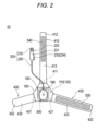
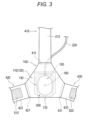
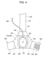
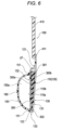
- Figs. 1 to 18 are views for describing a hemostatic device 10 according to the present embodiment.
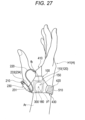
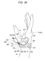
- Figs. 19 to 27 are views for describing a use example of the hemostatic device 10.
- the hemostatic device 10 can be used to stop bleeding at a puncture site (hereinafter, also referred to as a "first puncture site p1") formed in a hand H located on a distal side (fingertip side) of a forearm Ar of a patient when a sheath tube 610 of an introducer 600 placed at the first puncture site p1 is removed.
- a puncture site hereinafter, also referred to as a "first puncture site p1”
- first puncture site p1 formed in a hand H located on a distal side (fingertip side) of a forearm Ar of a patient when a sheath tube 610 of an introducer 600 placed at the first puncture site p1 is removed.
- a specific position of the puncture site where bleeding is to be stopped by the hemostatic device 10 is not particularly limited, but in the first embodiment, the first puncture site p1 and a second puncture site p2 are exemplified.
- the first puncture site p1 is a puncture site formed in a distal radial artery (hereinafter, also referred to as a "blood vessel V1") located on a distal side of a snuff box Sb of a palmar artery running on a dorsal side of a right hand H1 located on the distal side of the forearm Ar of the patient. Furthermore, the first puncture site p1 is located at a predetermined position avoiding a metacarpal bone B1 of an index finger and a metacarpal bone B2 of a thumb between the metacarpal bone B1 of the index finger and the metacarpal bone B2 of the thumb. Note that the snuff box Sb is a cavity of the hand located near a radius when the patient spreads the thumb of the hand H.
- the second puncture site p2 is a puncture site formed in an artery V2 located in the snuff box Sb of the palmar artery running on the dorsal side of the right hand H1.
- the second puncture site p2 is located on the forearm Ar side (proximal side) of the patient with respect to the first puncture site p1, and is located between an extensor pollicis longus muscle T1 and an extensor pollicis brevis muscle T2 located on the dorsal side of the right hand H1 of the patient.
- the second puncture site p2 is located at a predetermined position avoiding a position of the metacarpal bone B1 of the index finger and a position of the metacarpal bone B2 of the thumb.
- the hemostatic device 10 can also be applied to hemostasis of a puncture site on a left hand of a patient formed at a position corresponding to the first puncture site p1 exemplified with the patient's right hand H1 of the patient or a puncture site on the left hand of the patient formed at a position corresponding to the second puncture site p2 exemplified with the patient's right hand H1.
- hemostatic device 10 will be described in detail.
- the hemostatic device 10 generally includes a cover member 100 configured to cover the first puncture site p1, an inflatable member 150 connected to the cover member 100 and configured to compress the first puncture site p1, an injection member 200 connected to the inflatable member 150 and configured to be capable of injecting a fluid into the inflatable member 150, and a securing member 230 configured to be capable of securing the injection member 200 to the cover member 100.
- the inflatable member 150 includes an inner cavity 150a into which the fluid can be injected.
- the inflatable member 150 is configured to inflate as the fluid is injected into the inner cavity 150a and deflate as the fluid injected into the inner cavity 150a is discharged.
- the fluid used for the inflation of the inflatable member 150 is, for example, a gas such as air.
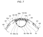
- Figs. 6 and 7 illustrate cross-sectional views of the inflatable member 150 in an inflated state.
- a tube member 220 (see Figs. 1 and 2 ) is coupled to the inner cavity 150a of the inflatable member 150.
- the inflatable member 150 can be formed of, for example, a film-shaped member (sheet material) connected to a sheet material 120 forming a main body 110 of the cover member 100.
- the inflatable member 150 can be disposed to form the inner cavity 150a against a lower surface region 132 of a retaining portion 130 formed by the sheet material 120.
- An outer peripheral edge of the film-shaped member forming the inflatable member 150 forms an edge portion 151 of the inflatable member 150.
- the edge portion 151 of the inflatable member 150 can be connected to the sheet material 120 by, for example, fusing bonding, adhesion, or the like.
- the film-shaped member forming the inflatable member 150 can be made of, for example, a resin material having a predetermined thickness.
- a material of the film-shaped member forming the inflatable member 150 is not particularly limited, and for example, polyvinyl chloride, polyethylene, polypropylene, polybutadiene, polyolefins such as ethylene-vinyl acetate copolymer (EVA), polyesters such as polyethylene terephthalate (PET) and polybutylene terephthalate (PBT), various thermoplastic elastomers such as polyvinylidene chloride, silicone, polyurethane, polyamide elastomer, polyurethane elastomer, polyester elastomer, nylon, nylon elastomer, or any combination thereof (such as a blend resin, a polymer alloy and a laminate) can be used.
- the cover member 100 to be described later can be made of, for example, a material similar to each of those exemplified above.
- the inflatable member 150 is disposed on an inner surface 110a side of the main body 110 of the cover member 100.
- the inner surface 110a of the main body 110 is formed of a surface disposed on the body surface side of the right hand H1 in the lower surface region 132 of the retaining portion 130 (see Figs. 23 and 24 ).
- An outer surface 110b of the main body 110 is formed of a surface on a surface facing the outside in an upper surface region 131 of the retaining portion 130.
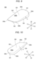
- Fig. 8 is a plan view of a support member 300 as seen from an outer face 300b side.
- Fig. 8 illustrates a positional relationship among the inflatable member 150 in a deflated state, the support member 300, and the retaining portion 130.
- the inflatable member 150 and the retaining portion 130 are indicated by two-dot chain lines.
- the inflatable member 150 has a longitudinal width wa passing through a center c1 of the inflatable member 150 and a lateral width wb that is orthogonal to the longitudinal width wa and passes through the center c1 of the inflatable member 150 in a state where the inflatable member 150 is deflated.
- the center c1 of the inflatable member 150 is located at a center of an outer shape illustrated in the plan view of Fig. 8 .
- the inflatable member 150 can be formed such that the lateral width wb is shorter than the longitudinal width wa.
- the inflatable member 150 has a substantially oval shape that is rotationally symmetric with respect to the center c1 in the plan view illustrated in Fig. 8 .
- the inflatable member 150 can be disposed such that the center c1 of the inflatable member 150 is located closer to a lower end 302 of the support member 300 than a center of gravity G1 of the outer shape of the support member 300.
- the inflatable member 150 includes a marker portion 160 for aligning the inflatable member 150 with the first puncture site p1.
- the marker portion 160 is located at a position overlapping the center c1 of the inflatable member 150 as illustrated in Fig. 8 .
- the marker portion 160 can include a transparent central portion surrounding the center c1 and a colored circular frame portion surrounding the central portion.
- the marker portion 160 is disposed on an outer face of the inflatable member 150. Note that the marker portion 160 may be disposed on an inner face of the inflatable member 150 facing the inner cavity 150a.
- the marker portion 160 can also include, for example, a circular marker configured entirely in color, a marker configured by a transparent central portion and a rectangular frame portion, a rectangular marker configured entirely in color, or the like.
- the planar shape of the inflatable member 150 is not limited only to the oval shape.
- the inflatable member 150 may have a planar shape such as a circle, an ellipse, or a rectangle.
- the inflatable member 150 may be formed by joining one sheet-like member with an edge portion of another sheet-like member in a state where the inner cavity 150a is formed between both the sheet-like members. In such a case, in the inflatable member 150, the surface of the one sheet-shaped member is connected to the sheet material 120 forming the main body 110 of the cover member 100. Furthermore, the inflatable member 150 can also be formed of, for example, one bag-shaped member shaped to include the inner cavity 150a inside. In such a case, in the inflatable member 150, a part of the surface of the bag-shaped member is connected to the sheet material 120 forming the main body 110 of the cover member 100.
- the cover member 100 includes the main body 110 in which the inflatable member 150 is located, a first band body 410 that is configured to be disposed between fingers of the patient and extends from the main body 110 in a first direction, a second band body 420 extending from the main body 110 in a second direction different from the first direction, and a third band body 430 facing the second band body 420 across the inflatable member 150 and extending from the main body 110 in a third direction different from the first direction and the second direction.
- the main body 110 includes the support member 300 made of a material harder than the inflatable member 150.
- the support member 300 is configured to overlap the inflatable member 150 in the plan view illustrated in Figs. 4 and 5 .
- the main body 110 has a two-layer structure and includes a retaining portion 130 retaining the support member 300.
- the retaining portion 130 includes the upper surface region 131 located on the outer face 300b side of the support member 300, the lower surface region 132 that is located on an inner face 300a side of the support member 300 and faces the upper surface region 131 across the support member 300, and a curved region 133 connecting the upper surface region 131 and the lower surface region 132 on a proximal side of the support member 300 (the lower end 302 side of the support member 300).
- the curved region 133 is formed by folding a part of the main body 110 toward the first band body 410 side.
- the retaining portion 130 having an insertion portion g into which the support member 300 can be inserted is configured by folding a part of the sheet material 120 forming the main body 110 from the proximal side to a distal side of the main body 110.
- a first end 121 located on the distal side of a folded part of the sheet material 120 is connected to the sheet material 120 at a position on the distal side of an upper end 301 of the support member 300.
- a proximal portion 122 of the cover member 100 is located in the curved region 133.
- the insertion portion g is closed between the first end 121 and the curved region 133 in a direction of the longitudinal width wa (see Fig. 11 ) of the inflatable member 150. Furthermore, as illustrated in Fig. 7 , in the retaining portion 130, the insertion portion g communicates with the outside on the second band body 420 side and the third band body 430 side in a direction of the lateral width wb (see Fig. 11 ) of the inflatable member 150.
- each of the band bodies 410, 420, and 430 can be connected to any position in a region surrounding the periphery of the retaining portion 130 in the main body 110. Furthermore, each of the band bodies 410, 420, and 430 can be connected to a surface disposed on a body surface side of the right hand H1 in the above region. Each of the band bodies 410, 420, and 430 can be connected to the main body 110 by, for example, fusion bonding or adhesion. Note that each of the band bodies 410, 420, and 430 may be integrally formed with the main body 110.
- the first band body 410 includes one end 411 connected to the main body 110 of the cover member 100, the other end 412 located opposite to the one end 411, and a main body 413 extending between the one end 411 and the other end 412.
- the first band body 410 can be disposed so as to be hooked on an interdigital part fb located between the thumb and the index finger of the right hand H1 of the patient in a state where the inflatable member 150 is disposed at the first puncture site p1.
- the second band body 420 includes one end 421 connected to the main body 110 of the cover member 100, the other end 422 located opposite to the one end 421, and a main body 423 extending between the one end 421 and the other end 422.
- the third band body 430 includes one end 431 connected to the main body 110 of the cover member 100, the other end 432 located opposite to the one end 431, and a main body 433 extending between the one end 431 and the other end 432.
- the second band body 420 and the third band body 430 can be disposed so as to be wrapped along the outer periphery of the right hand H1 when the hemostatic device 10 is worn on the right hand H1 of the patient.
- a constituent material of each of the band bodies 410, 420, and 430 is not particularly limited, and can be made of, for example, a vinyl chloride resin, a polyurethane resin, a polyester resin, or the like. Furthermore, a shape, a length, a thickness, and the like of each of the band bodies 410, 420, and 430 are not particularly limited.
- securing parts that is, a first securing part 510, a second securing part 520, a third securing part 530, and a fourth securing part 540, which enable the cover member 100 to be secured on the right hand H1, are disposed in the band bodies 410, 420, and 430, respectively.
- the first securing part 510 is disposed on an outer face of the main body 423 of the second band body 420.
- the second securing part 520 is disposed on an outer face of the main body 433 of the third band body 430.
- the third securing part 530 is disposed on an inner face of the main body 423 of the second band body 420.
- the fourth securing part 540 is disposed on an inner face of the main body 413 of the first band body 410.
- the first securing part 510 and the second securing part 520 are formed of a male side of a hook-and-loop fastener.
- the third securing part 530 and the fourth securing part 540 are formed of a female side of the hook-and-loop fastener.
- the hook-and-loop fastener in the present specification is a hook-and-loop fastener, and is, for example, Magic Tape (registered trademark) or Velcro (registered trademark).
- the second band body 420 and the third band body 430 are configured to be detachably attached via the third securing part 530 located on the inner face of the main body 423 of the second band body 420 and the second securing part 520 located on the outer face of the main body 433 of the third band body 430. Furthermore, the first band body 410 and the second band body 420 are configured to be detachably attached via the fourth securing part 540 located on the inner face of the main body 413 of the first band body 410 and the first securing part 510 located on the outer face of the main body 423 of the second band body 420.
- each of the securing parts 510, 520, 530, and 540 is not limited as long as the cover member 100 can be secured on the right hand H1 by connecting the band bodies 410, 420, and 430 to each other in a state where the hemostatic device 10 is disposed on the right hand H1.
- a change of a position where the securing part is disposed in each of the band bodies 410, 420, and 430, and the like can be arbitrarily performed.
- each of the securing parts 510, 520, 530, and 540 is formed of the hook-and-loop fastener
- the male side and the female side of the hook-and-loop fastener may be interchanged.
- the securing parts 510, 520, 530, and 540 may be configured using, for example, coupling mechanisms or the like including a frame portion in which a snap, a button, a clip, or a protrusion is formed and an engaged portion in which a hole engageable with the frame portion is formed.
- Figs. 8 to 10 illustrate the support member 300.
- arrows X1 and X2 indicate a longitudinal direction of the support member 300 (the same direction as the direction of the longitudinal width wa of the inflatable member 150)
- arrows Y1 and Y2 indicate a width direction of the support member 300 (the same direction as the direction of the lateral width wb of the inflatable member 150)
- arrows Z1 and Z2 indicate a thickness direction of the support member 300.
- the support member 300 can be disposed in the insertion portion g of the retaining portion 130.
- the support member 300 includes the upper end 301 that is located on the first band body 410 side and forms an end of the support member 300, the lower end 302 forming an end opposite to the upper end 301, and a pair of side surface portions 303 and 304 connecting the upper end 301 and the lower end 302.
- the upper end 301 can be disposed on a fingertip side (distal side) of the finger in a state where the hemostatic device 10 is worn on the right hand H1 of the patient.
- the lower end 302 can be disposed on the forearm Ar side (proximal side) in the state where the hemostatic device 10 is worn on the right hand H1 of the patient.
- the upper end 301 forms a distal portion of the support member 300
- the lower end 302 forms a proximal portion of the support member 300.
- the upper end 301 of the support member 300 has a flat portion 301a that is linear in the plan view illustrated in Fig. 8 .
- the flat portion 301a extends substantially linearly between corners 306c and 306d located on the upper end 301 side.
- the lower end 302 of the support member 300 has a flat portion 302a that is linear in the plan view illustrated in Fig. 8 .
- the flat portion 302a extends substantially linearly between corners 306a and 306b located on the lower end 302 side.
- the support member 300 has an intermediate portion 305 located between the upper end 301 and the lower end 302 in the plan view illustrated in Fig. 8 .
- the intermediate portion 305 is located in the middle in the longitudinal direction connecting the upper end 301 and the lower end 302.
- the outer face 300b of the support member 300 is curved toward the second band body 420 and the third band body 430.
- the outer face 300b of the support member 300 can be formed to have a substantially constant radius of curvature at each portion in the longitudinal direction of the support member 300, for example.
- the support member 300 is located to have the center of gravity G1 of the outer shape of the support member 300 in the plan view illustrated in Fig. 8 .
- a width w1 of the upper end 301 is formed to be larger than a width w2 of the lower end 302 such that the center of gravity G1 is located on the upper end 301 side of the intermediate portion 305.
- the support member 300 has a substantially trapezoidal shape in which the width w1 of the upper end 301 is larger than the width w2 of the lower end 302.
- the center of gravity G1 of the support member 300 is located at a position shifted from the intermediate portion 305 of the support member 300 to the upper end 301 side (a lower bottom side of the trapezoidal shape) by a predetermined distance.
- the width w1 of the upper end 301 of the support member 300 is defined by a dimension (maximum width) of a part having the largest width in a region located on the upper end 301 side of the intermediate portion 305 of the support member 300.
- the width w2 of the lower end 302 of the support member 300 can be defined by a length of a straight line connecting a boundary between the side surface portion 303 and the corner 306a and a boundary between the side surface portion 304 and the corner 306b.
- the boundary between the side surface portion 303 and the corner 306a is a position where a tangent line of the side surface portion 303 starts to change in a curved manner.
- the boundary between the side surface portion 304 and the corner 306b is a position where a tangent line of the side surface portion 304 starts to change in a curved manner.
- the width w2 of the lower end 302 of the support member 300 can be defined by a length of a straight line connecting apexes located at the corners 306a and 306b.
- the inner face 300a of the support member 300 is curved toward the second band body 420 and the third band body 430. That is, as illustrated in Figs. 7 and 10 , the inner face 300a of the support member 300 is curved in a shape projecting in a direction away from the inflatable member 150.
- the inner face 300a of the upper end 301 of the support member 300 can be formed to have a radius of curvature smaller than a radius of curvature of the inner face 300a of the lower end 302 of the support member 300, for example.
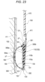
- the support member 300 is configured such that a thickness t1 of each of the side surface portions 303 and 304 connecting the upper end 301 and the lower end 302 becomes thinner from the upper end 301 to the lower end 302. Therefore, the support member 300 is inclined such that a distance between the outer face 300b and the inner face 300a decreases from the upper end 301 to the lower end 302 in the cross-sectional view illustrated in Fig. 6 and a cross-sectional view illustrated in Fig. 23 .
- Each of the corners 306a, 306b, 306c, and 306d located at the four corners of the support member 300 is formed in a curved shape that is rounded.
- the hemostatic device 10 is preferably formed such that a part where the marker portion 160 of the inflatable member 150 is provided, a part overlapping the marker portion 160 in the cover member 100 (the upper surface region 131 and the lower surface region 132 of the retaining portion 130), and a part overlapping the marker portion 160 in the support member 300 are transparent.
- the operator can easily visually confirm a position of the marker portion 160 disposed on the inflatable member 150 and/or the first puncture site p1 via the parts formed to be transparent in the members 100, 150, and 300 when the hemostatic device 10 is worn on the right hand H1 of the patient as illustrated in Figs. 20 to 22 .
- transparent in the present specification includes colored transparent, colorless transparent, and translucent.
- acrylic resin for example, acrylic resin, polyvinyl chloride (particularly hard polyvinyl chloride), polyolefin such as polyethylene, polypropylene, or polybutadiene, polystyrene, poly- (4-methylpentene-1), polycarbonate, ABS resin, polymethyl methacrylate (PMMA), polyacetal, polyacrylate, polyacrylonitrile, polyvinylidene fluoride, ionomer, acrylonitrile-butadiene-styrene copolymer, polyethylene terephthalate (PET), or the like, can be used.
- acrylic resin for example, acrylic resin, polyvinyl chloride (particularly hard polyvinyl chloride), polyolefin such as polyethylene, polypropylene, or polybutadiene, polystyrene, poly- (4-methylpentene-1), polycarbonate, ABS resin, polymethyl methacrylate (PMMA), polyacetal, polyacrylate, polyacrylonitrile, polyvinylidene fluor
- the injection member 200 includes a connector portion 210 and the tube member 220 coupled to the connector portion 210 and the inflatable member 150.
- the connector portion 210 includes a port portion 211 disposed outside the securing member 230 and a valve portion 213 disposed inside the main body 231 of the securing member 230.
- the valve portion 213 is briefly illustrated in each drawing, and is not illustrated in some drawings.
- a fluid supply tool for supplying the fluid to the inner cavity 150a of the inflatable member 150 can be connected to the connector portion 210.
- the fluid supply tool for example, a syringe (not illustrated in the present specification) can be used.
- the valve portion 213 can be formed of, for example, a check valve.
- the valve portion 213 maintains a closed state in a state where a cylindrical distal end portion of the syringe is not inserted into the connector portion 210.
- the valve portion 213 blocks communication between a lumen of the tube member 220 and the outside of the connector portion 210.
- the valve portion 213 is opened when the cylindrical distal end portion of the syringe is inserted into the connector portion 210.
- the lumen of the tube member 220 communicates with the inside of the cylindrical distal end portion of the syringe via an internal space 231a (see Fig. 12 ) of the main body 231 in which the valve portion 213 is located.
- one end of the tube member 220 is coupled to the inflatable member 150.
- the other end of the tube member 220 is coupled to the main body 231 of the securing member 230.
- the other end of the tube member 220 is located in the internal space 231a of the main body 231 of the securing member 230.
- the lumen of the tube member 220 communicates with the internal space 231a of the main body 231 via the other end of the tube member 220. Therefore, the inner cavity 150a of the inflatable member 150 communicates with the internal space 231a of the main body 231 of the securing member 230 via the lumen of the tube member 220.
- the operator When the inflatable member 150 is to be inflated, the operator inserts the cylindrical distal end portion of the syringe (not illustrated) into the connector portion 210 to open the valve portion 213. The operator injects air in the syringe into the inner cavity 150a of the inflatable member 150 by pushing a pusher of the syringe in a state where the valve portion 213 is open. When the air is injected into the inner cavity 150a, the inflatable member 150 inflates.
- the operator When the inflatable member 150 is to be deflated, the operator inserts the cylindrical distal end portion of the syringe into the connector portion 210 and further pulls the pusher of the syringe. The operator can discharge the air in the inner cavity 150a of the inflatable member 150 to the syringe by performing the above operation.
- Figs. 11 to 14 illustrate the securing member 230 as seen from each direction.
- Figs. 15 and 16 illustrate states when the securing member 230 is secured to the cover member 100.
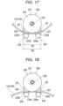
- Figs. 17 and 18 illustrate states where the securing member 230 is secured to the cover member 100.
- the securing member 230 includes the main body 231 connecting the connector portion 210 and the tube member 220, claw portions 233 and 234 extending in parallel with the main body 231 toward the inflatable member 150 side, and coupling portions 236 and 237 that are configured to be capable of inserting the cover member 100 between the main body 231 and the claw portions 233 and 234, respectively, and couple the main body 231 and the claw portions 233 and 234, respectively.
- the other end of the tube member 220 is coupled to the main body 231.
- a side of the securing member 230 to which the other end of the tube member 220 is coupled is referred to as a "distal side”
- a side of the securing member 230 on which the port portion 211 is disposed is referred to as a "proximal side”.
- the main body 231 has the two claw portions 233 and 234.
- the claw portion 233 is referred to as a "first claw portion 233”
- the claw portion 234 is referred to as a "second claw portion 234".
- the first claw portion 233 and the second claw portion 234 extend in parallel with each other.
- a gap g2 into which the cover member 100 can be inserted is formed between the first claw portion 233 and the main body 231 and between the second claw portion 234 and the main body 231.
- a width w3 of the first claw portion 233 and the second claw portion 234 is smaller than a width w4 of the main body 231 at positions where the first claw portion 233 and the second claw portion 234 overlap the main body 231 in a plan view.
- the above plan view means a plan view as seen from a bottom surface side illustrated in Fig. 14 or a plan view as seen from an upper surface side opposite to the bottom surface side.
- the main body 231 has the two claw portions 233 and 234.
- the width w3 of the first claw portion 233 and the second claw portion 234 is defined by a distance between outermost peripheral positions of the claw portions 233 and 234 farthest from a position of a center of the main body 231 as illustrated in Figs. 14 and 17 .
- the hemostatic device 10 can secure the securing member 230 to the cover member 100 by inserting the cover member 100 between the claw portions 233 and 234 and the gaps g2.
- the operator can easily insert the cover member 100 into the gaps g2 by bringing the claw portions 233 and 234 close to the cover member 100 along a direction substantially parallel with a plane direction of the cover member 100.
- it is possible to prevent a force in a direction of pressing the cover member 100 against the body surface side of the right hand H1 of the patient from being inadvertently applied to the hemostatic device 10 when the securing member 230 is secured to the cover member 100.
- the width w3 of the first claw portion 233 and the second claw portion 234 of the securing member 230 is smaller than the width w4 of the main body 231, the following effects are obtained.
- the cover member When the hemostatic device is worn on the right hand H1 of the patient, the cover member may be curved following a movement of the right hand H1 of the patient.
- the cover member 100 is curved in a shape recessed toward the main body 231 side as illustrated in Fig. 17 , or is curved in a shape projecting toward the main body 231 side as illustrated in Fig. 18 .
- a radius of curvature of the cover member a radius of curvature when a shape of the cover member in a front view is assumed to be an arc
- the cover member easily interferes with the claw portions when the cover member is to be inserted into the gap g2.
- the cover member in a case where the width of the first claw portion and the second claw portion are larger than the width of the main body, if the cover member is curved in the shape projecting toward the main body side as illustrated in Fig. 18 , the cover member more easily interferes with the first claw portion and the second claw portion. As a result, it is difficult to smoothly insert the cover member into the gap in the hemostatic device.
- the width w3 of the first claw portion 233 and the second claw portion 234 is smaller than the width w4 of the main body 231 at the positions where the first claw portion 233 and the second claw portion 234 overlap the main body 231 in the plan view. Therefore, even in the case where the cover member 100 is curved in the shape projecting toward the main body 231 side as described above, the hemostatic device 10 can suppress the interference of the first claw portion 233 and the second claw portion 234 with the cover member 100 when the cover member 100 is inserted into the gap g2.
- the main body 231 includes an inclined portion 232 inclined toward the claw portions 233 and 234.
- the inclined portion 232 is configured such that at least a part of the inclined portion 232 is located on the proximal side of distal ends 233a and 234a of the claw portions 233 and 234. In the embodiment illustrated in Fig. 11 , the inclined portion 232 extends from a position on the distal side of the distal ends 233a and 234a of the claw portions 233 and 234 to a position on the proximal side of the distal ends 233a and 234a of the claw portions 233 and 234. As illustrated in Figs.
- the operator moves the cover member 100 toward the gap g2 from the position on the distal side of the distal ends 233a and 234a of the claw portions 233 and 234.
- the inclined portion 232 guides the cover member 100 toward the gap g2 along the inclined portion 232 while adjusting the shape of the cover member 100. Since the inclined portion 232 extends from the position on the distal side of the distal ends 233a and 234a of the claw portions 233 and 234 to the position on the proximal side of the distal ends 233a and 234a of the claw portions 233 and 234 in the embodiment of Fig.
- the cover member 100 can be efficiently guided to positions of the distal ends 233a and 234a of the claw portions 233 and 234 along the inclined portion 232.
- the inclined portion 232 assists the insertion of the cover member 100 into the gap g2 by guiding the movement of the cover member 100. Therefore, the operator can smoothly insert the cover member 100 into the gap g2.
- the main body 231 can be configured to have a cylindrical outer shape. Furthermore, the main body 231 can be configured to have a circular cross-sectional shape in a direction orthogonal to an extending direction of the main body 231 as illustrated in Fig. 12 .
- the securing member 230 may receive various external forces in a state where the cover member 100 is inserted into the gap g2.
- the main body 231 of the securing member 230 has a circular cross-sectional shape. Therefore, when an external force is applied to the main body 231, the securing member 230 can divert the external force along an outer face of the main body 231.
- the securing member 230 is formed to have a cross-sectional shape such as a quadrangle, when an external force is applied to the main body 231 as described above, the external force cannot be sufficiently diverted along the outer face of the main body 231. Therefore, there is a possibility that the hemostatic device 10 is displaced or inclined when the external force is applied to the main body 231.
- the main body 231 of the securing member 230 has the circular cross-sectional shape, it is possible to suitably prevent the main body 231 and the cover member 100 from interfering even in a case where the cover member 100 is formed in the curved shape recessed toward the main body 231 side as illustrated in Fig. 17 or a case where the cover member 100 is formed in the curved shape projecting toward the main body 231 side as illustrated in Fig. 18 .
- the cover member 100 is curved as illustrated in Figs.
- the cover member 100 interferes with the corners of the main body 231 when the cover member 100 is inserted into the gap g2 so that the cover member 100 cannot be smoothly inserted into the gap g2.
- the main body 231 can exhibit the above-described effect of diverting an external force even in a case where the main body has an elliptical cross-sectional shape. Therefore, the main body 231 is preferably formed to have the circular or elliptical cross-sectional shape from the viewpoint of exhibiting the effect of diverting an external force.
- each of the claw portions 233 and 234 has a cylindrical outer shape.
- the claw portions 223 and 234 have, on upper surfaces on the main body 231 side, flat portions 233b and 234b, respectively, configured to maintain a part of the cover member 100 in a flat shape in a state where the cover member 100 is inserted between the main body 231 and the claw portions 233 and 234.
- Each of the flat portions 233b and 234b extends linearly in a side view illustrated in Fig. 13 .
- Each of the flat portions 233b and 234b extends in substantially parallel with the extending direction of the main body 231 and faces the main body 231 across the gap g2 formed against the main body 231.
- the coupling portions 236 and 237 are curved from the main body 231 toward the distal ends 233a and 234a of the claw portions 233 and 234, respectively.
- a shape of the coupling portion 236 is not clearly illustrated in Figs. 11 and 13 , but the coupling portion 236 has substantially the same shape as the coupling portion 237, and is curved toward the distal end 233a side of the first claw portion 233 similarly to the coupling portion 237.
- the operator can cause the hemostatic device 10 to be worn on the patient in a state where the securing member 230 is secured to the cover member 100. Since each of the coupling portions 236 and 237 has the curved shape as described above, even if each of the coupling portions 236 and 237 comes into contact with the body surface or the like of the right hand H1 of the patient when the hemostatic device 10 is worn on the patient in a state where the securing member 230 is connected to the cover member 100, the hemostatic device 10 can prevent pain or the like from being given to the patient.
- each of the coupling portions 236 and 237 has the curved shape as described above, the hemostatic device 10 can prevent each of the coupling portions 236 and 237 from biting into the skin when the patient performs an operation of touching a table stand with the right hand H1 or the like while the securing member 230 is secured to the cover member 100.
- the distal ends 233a and 234a of the claw portions 233 and 234 can be formed in a rounded shape. Since the distal ends 233a and 234a of the claw portions 233 and 234 are formed in the rounded shape in the securing member 230, it is possible to prevent the inflatable member 150 from being damaged in a case where the claw portions 233 and 234 unintentionally come into contact with the inflatable member 150 or the like.
- the distal ends 233a and 234a of the claw portions 233 and 234 are formed in the rounded shape in the securing member 230, it is possible to reduce the pain felt by the patient even if the claw portions 233 and 234 erroneously hit the body surface of the patient when the securing member 230 is mounted on the cover member 100.
- the securing member 230 has the two cylindrical claw portions 233 and 234.
- the number and shapes of the claw portions 233 and 234 disposed on the securing member 230 are not particularly limited. However, in a case where a claw portion is formed in a cylindrical shape, it is preferable to form two or more claw portions 233 and 234 with a predetermined distance therebetween as illustrated in the present embodiment. This is for the following reason.
- the securing member 230 when configured to include one cylindrical claw portion, a contact area between the cover member 100 and the claw portion becomes excessively small in a state where the cover member 100 is inserted into the gap g2, and it becomes difficult to support the cover member 100 in a stable state between the claw portion and the main body 231.
- the cover member 100 can be supported in a stable state between each of the claw portions 233 and 234 and the main body 231 by providing the predetermined distance between the two claw portions 233 and 234.
- a claw portion is preferably configured such that the cover member 100 inserted between the main body 231 and the claw portion can maintain a flat shape.
- the cover member 100 inserted between the main body 231 and the claw can maintain the flat shape, the operability when the claw portion is inserted and removed with respect to the cover member 100 is improved.
- claw portions are preferably disposed with a predetermined distance therebetween, for example, like the two claw portions 233 and 234 illustrated in the present embodiment. Since the predetermined distance is provided between the two claw portions 233 and 234, the securing member 230 can support the cover member 100 in a wider range in a direction in which the two claw portions 233 and 234 are arranged side by side.
- the securing member 230 can maintain the cover member 100 in the flat shape between the main body 231 and each of the claw portions 233 and 234.
- a position at which the securing member 230 is secured to the cover member 100 is not particularly limited.
- the securing member 230 can be secured at a position where a gap in which the claw portions 233 and 234 of the securing member 230 can be disposed is formed between the cover member 100 and the body surface of the right hand H1 when the inflatable member 150 inflates.
- a part located between the first band body 410 and the second band body 420 in the main body 110 (see Fig. 22 ) or a part near the proximal portion 122 of the cover member 100 located on the second band body 420 side (see Fig. 25 ) can be selected.
- a position where the securing member 230 is connected to the cover member 100 is not particularly limited as long as the tube member 220 is not forcibly pulled when the inflatable member 150 inflates at the position, and for example, the securing member 230 may be secured to the first band body 410 as illustrated in Fig. 26 , or the securing member 230 may be secured to the second band body 420 as illustrated in Fig. 27 .
- Fig. 20 illustrates a state where various procedures performed using the sheath tube 610 of the introducer 600 inserted into the first puncture site p1 are completed.
- the operator When causing the hemostatic device 10 to be worn on the right hand H1 of the patient, the operator disposes the inflatable member 150 and the support member 300 so as to overlap the first puncture site p1 as illustrated in Fig. 20 . At this time, the operator can appropriately align the inflatable member 150 and the support member 300 with the first puncture site p1 by disposing the marker portion 160 at the first puncture site p1 while visually confirming a position of the marker portion 160 disposed at the inflatable member 150.
- the operator can dispose the support member 300 so as to overlap the metacarpal bone B1 of the index finger and the metacarpal bone B2 of the thumb.
- An interval between the metacarpal bone B1 of the index finger and the metacarpal bone B2 of the thumb gradually narrows from the fingertip side to the forearm Ar side (see Fig. 19 ).
- a width of the support member 300 decreases from the upper end 301 disposed on the fingertip side to the lower end 302 disposed on the forearm Ar side (see Fig. 8 ).
- the operator can dispose the support member 300 along the metacarpal bones B1 of the index finger and the metacarpal bones B2 of the thumb by disposing the support member 300 so as to overlap the metacarpal bones B1 of the index finger and the metacarpal bones B2 of the thumb from the dorsal side of the right hand H1 of the patient.
- the operator can prevent a gap from being formed between the inflatable member 150 disposed on the inner face 300a side of the support member 300 and the right hand H1 by disposing the support member 300 along the metacarpal bone B1 of the index finger and the metacarpal bone B2 of the thumb.
- the operator wraps the second band body 420 and the third band body 430 along the outer periphery of the right hand H1 of the patient.
- the operator can connect the second band body 420 and the third band body 430 via the securing parts 520 and 530 by bringing the third securing part 530 (see Fig. 2 ) disposed on the inner surface of the second band body 420 into contact with the second securing part 520 (see Fig. 1 ) disposed on the outer surface of the third band body 430.
- the operator can firmly wrap each of the band bodies 420 and 430 along the outer periphery of the right hand H1 by connecting the band bodies 420 and 430 to each other in a state where the support member 300 overlaps the metacarpal bone B1 of the index finger and the metacarpal bone B2 of the thumb.
- the outer face 300b of the support member 300 is curved toward the second band body 420 side (the side surface portion 303 side) and the third band body 430 side (the side surface portion 304 side) (see Figs. 5 , 7 , and 9 ). Therefore, the operator can press the support member 300 against the right hand H1 from the outer face 300b side so as to be along the outer periphery of the right hand H1 as illustrated in Fig. 24 by wrapping the second band body 420 and the third band body 430 along the right hand H1 of the patient as illustrated in Fig. 21 . Therefore, the hemostatic device 10 can enhance a force of securing the support member 300 and the inflatable member 150 with respect to the right hand H1 of the patient.
- the operator disposes a part of the first band body 410 on the palm side of the right hand H1 of the patient while passing the first band body 410 through the interdigital part fb located between the thumb and the index finger of the right hand H1 of the patient.
- the operator can connect the first band body 410 and the second band body 420 via the securing parts 510 and 540 by bringing the fourth securing part 540 (see Fig. 2 ) disposed on the inner face of the first band body 410 into contact with the first securing part 510 (see Fig. 1 ) disposed on the outer face of the second band body 420.
- An inclined part exists in each portion (for example, the vicinity of the snuff box Sb) of the right hand H1 of the patient (see Fig. 19 ). Furthermore, a shape of the inclined part of the right hand H1 depends on an individual difference of the patient. For example, in a case where the inner face of the support member is formed in a flat shape, it is difficult to dispose the support member along the inclined part of the right hand H1. In the hemostatic device 10, the inner face 300a of the support member 300 is curved in the shape projecting in the direction away from the inflatable member 150 (see Figs. 7 and 24 ).
- the inner face 300a of the support member 300 can be disposed along the right hand H1 of the patient by disposing the inner face 300a of the support member 300 so as to overlap the inclined part of the right hand H1 of the patient.
- the hemostatic device 10 can dispose the support member 300 to overlap the first puncture site p1 without depending on a dominant hand of the patient or the way of placement by the operator. Therefore, in the hemostatic device 10, the support member 300 can be appropriately disposed at a desired position near the first puncture site p1.
- the operator connects the syringe to the port portion 211 in a state where the hemostatic device 10 is worn on the right hand H1 of the patient through the above process.
- the operator operates the syringe to inject air into the inflatable member 150, thereby inflating the inflatable member 150.
- the inflatable member 150 applies a compressive force to the first puncture site p1.
- the operator can strongly tighten the first band body disposed in the interdigital part fb, for example, in order to enhance the force of securing the support member with respect to the right hand H1 of the patient.
- the operator can firmly secure the support member to the right hand H1 of the patient by strongly tightening the first band body even if the support member is disposed in an unstable state on the right hand H1 of the patient.
- the patient sometimes feels pain when the first band body is strongly tightened. Therefore, in a case where the first band body cannot be strongly tightened due to the pain felt by the patient or the like, the hemostatic device may be disposed such that the inner face of the support member is inclined with respect to the body surface of the right hand H1 of the patient. Specifically, the upper end of the support member on which the first band body is disposed lifts-off to a position excessively away from the body surface of the right hand H1 of the patient as compared with the lower end located opposite to the upper end.
- the support member is disposed to be inclined such that a distance between the inner face of the support member and the body surface of the right hand H1 of the patient gradually decreases from the upper end to the lower end of the support member.
- the hemostatic device 10 is configured such that the thickness t1 of each of the side surface portions 303 and 304 of the support member 300 becomes thinner from the upper end 301 to the lower end 302.
- the first band body 410 configured to be disposed at the interdigital part fb located between the fingers of the patient extends from the upper end 301 side of the support member 300, and is configured to press the upper end 301 side of the support member 300 against the right hand H1 of the patient.
- the inflatable member 150 when the inflatable member 150 starts to inflate in a state where the support member 300 and the inflatable member 150 are secured to the right hand H1 of the patient, the inflatable member 150 applies a force to the vicinity of the upper end 301 of the support member 300.
- the upper end 301 side of the support member 300 is lifted by the force applied by the inflatable member 150.
- the support member 300 is disposed such that the inner face 300a of the support member 300 is substantially parallel with the body surface of the right hand H1 of the patient in a state where the inflatable member 150 inflates as illustrated in Fig. 23 . Therefore, the hemostatic device 10 can apply a compressive force in a direction perpendicular to the first puncture site p1 when the inflatable member 150 inflates.
- the inner face 300a of the support member 300 is curved toward the second band body 420 side and the third band body 430 side (see Fig. 7 ).
- the hemostatic device 10 is disposed such that the inner face 300a of the support member 300 is along the body surface of the right hand H1 of the patient in a state where the inflatable member 150 inflates.
- the hemostatic device 10 presses the inflatable member 150 along the body surface of the right hand H1 of the patient by the inner face 300a of the support member 300.
- the hemostatic device 10 can effectively enhance the compressive force applied to the first puncture site p1 by the inflatable member 150 as compared with a case where the inner face 300a of the support member 300 is formed in a flat surface shape.
- the operator removes the sheath tube 610 of the introducer 600 from the first puncture site p1 as illustrated in Fig. 22 .
- the operator confirms that there is no bleeding from the first puncture site p1 during hemostasis performed using the hemostatic device 10. In a case where there is bleeding from the first puncture site p1, the operator can adjust an injection amount of air into the inflatable member 150.
- the operator can stop bleeding at the first puncture site p1 formed on the right hand H1 of the patient using the hemostatic device 10.
- the operator can secure the securing member 230 to the cover member 100 as illustrated in Fig. 22 in a state where the inflatable member 150 inflates.
- the operator can prevent the tube member 220 from moving following the movement of the right hand H1 of the patient in the state where the hemostatic device 10 is worn by securing the securing member 230 to the cover member 100.
- the operator can also secure the securing member 230 to the cover member 100 in advance before inflating the inflatable member 150, and inflate the inflatable member 150 after the hemostatic device 10 is worn on the right hand H1 of the patient.
- the hemostatic device 10 includes the cover member 100 configured to cover the first puncture site p1, the inflatable member 150 connected to the cover member 100 and configured to compress the first puncture site p1, the injection member 200 connected to the inflatable member 150 and configured to be capable of injecting a fluid into the inflatable member 150, and the securing member 230 configured to be capable of securing the injection member 200 to the cover member 100.
- the injection member 200 includes the connector portion 210 and the tube member 220 coupled to the inflatable member 150.
- the securing member 230 includes the main body 231 connecting the connector portion 210 and the tube member 220, the claw portions 233 and 234 extending in parallel with the main body 231 toward the inflatable member 150 side, and the coupling portions 236 and 237 that are configured to be capable of inserting the cover member 100 between the main body 231 and the claw portions 233 and 234, respectively, and couple the main body 231 and the claw portions 233 and 234, respectively.
- the width w3 of the claw portions 233 and 234 is smaller than the width w4 of the main body 231 at the positions where the claw portions 233 and 234 overlap the main body 231 in the plan view.
- the injection member 200 can be secured to the cover member 100 by inserting the cover member 100 between the main body 231 and the claw portions 233 and 234 in the state where the main body 231 of the securing member 230 connects the connector portion 210 and the tube member 220.
- the operator can insert the cover member 100 between the main body 231 and the claw portions 233 and 234 by bringing the securing member 230 close to the cover member 100 along the direction substantially parallel with the plane direction of the cover member 100.
- the operator when securing the injection member 200 to the cover member 100, the operator can prevent an unnecessary force from being applied in a direction of pressing the hemostatic device 10 against the body surface of the right hand H1 of the patient. Therefore, when the injection member 200 is secured to the cover member 100, the hemostatic device 10 can prevent the hemostatic device 10 worn on the right hand H1 of the patient from being displaced or the inflatable member 150 from being displaced. Furthermore, for example, the cover member 100 may be curved following the movement of the body in a state where the hemostatic device 10 is worn on the patient.
- the cover member 100 is curved in a case where the width w3 of the claw portions 233 and 234 is formed to be larger than the width w4 of the main body 231 at the positions where the claw portions 233 and 234 overlap the main body 231, the claw portions 233 and 234 easily interfere with the cover member 100 when the cover member 100 is inserted between the main body 231 and the claw portions 233 and 234.
- the width w3 of the claw portions 233 and 234 is smaller than the width w4 of the main body 231 at the positions where the claw portions 233 and 234 overlap the main body 231 in the plan view. Therefore, in the hemostatic device 10 described above, the cover member 100 can be smoothly inserted between the main body 231 and the claw portions 233 and 234 even when the cover member 100 is curved following the movement of the right hand H1 of the patient.
- the hemostatic device 10 includes the cover member 100 configured to cover the first puncture site p1, the inflatable member 150 connected to the cover member 100 and configured to compress the first puncture site p1, the injection member 200 connected to the inflatable member 150 and configured to be capable of injecting a fluid into the inflatable member 150, and the securing member 230 configured to be capable of securing the injection member 200 to the cover member 100.
- the injection member 200 includes the connector portion 210 and the tube member 220 coupled to the inflatable member 150.
- the securing member 230 includes the main body 231 connecting the connector portion 210 and the tube member 220, the claw portions 233 and 234 extending in parallel with the main body 231 toward the inflatable member 150 side, and the coupling portions 236 and 237 that are configured to be capable of inserting the cover member 100 between the main body 231 and the claw portions 233 and 234, respectively, and couple the main body 231 and the claw portions 233 and 234, respectively.
- the main body 231 has the inclined portion 232 inclined toward the claw portions 233 and 234, and at least a part of the inclined portion 232 is configured to be located at the position on the proximal side of the distal ends 233a and 234a of the claw portions 233 and 234 in the main body 231.
- the injection member 200 can be secured to the cover member 100 by inserting the cover member 100 between the main body 231 and the claw portions 233 and 234 in the state where the main body 231 of the securing member 230 connects the connector portion 210 and the tube member 220.
- the operator can insert the cover member 100 between the main body 231 and the claw portions 233 and 234 by bringing the securing member 230 close to the cover member 100 along the direction substantially parallel with the plane direction of the cover member 100. Therefore, when securing the injection member 200 to the cover member 100, the operator can prevent an unnecessary force from being applied in a direction of pressing the hemostatic device 10 against the body surface of the right hand H1 of the patient.
- the hemostatic device 10 can prevent the hemostatic device 10 worn on the right hand H1 of the patient from being displaced or the inflatable member 150 from being displaced. Furthermore, the hemostatic device 10 is configured such that the main body 231 has the inclined portion 232 inclined toward the claw portions 233 and 234. Furthermore, at least a part of the inclined portion 232 of the main body 231 is configured to be located at the position on the proximal side of the distal ends 233a and 234a of the claw portions 233 and 234 in the main body 231.
- the hemostatic device 10 is configured such that when the operator inserts the cover member 100 between the main body 231 and the claw portions 233 and 234, the inclined portion 232 guides the cover member 100 to a position closer to the coupling portions 236 and 237 than the distal ends 233a and 234a of the claw portions 233 and 234. Therefore, when inserting the cover member 100 between the main body 231 and the claw portions 233 and 234, the operator can smoothly insert the cover member 100 between the main body 231 and the claw portions 233 and 234 while adjusting the shape of the cover member 100 by guiding the cover member 100 along the inclined portion 232.
- the main body 231 has the inclined portion 232 inclined toward the claw portions 233 and 234.
- the inclined portion 232 extends from the position on the distal side of the distal ends 233a and 234a of the claw portions 233 and 234 to the position on the proximal side of the distal ends 233a and 234a of the claw portions 233 and 234.
- the inclined portion 232 efficiently guides the cover member 100 to the positions of the distal ends 233a and 234a of the claw portions 233 and 234 when the cover member 100 is inserted into the gap g2.
- the inclined portion 232 assists the insertion of the cover member 100 into the gap g2 when the cover member 100 is inserted into the gap g2. Therefore, the operator can smoothly insert the cover member 100 into the gap g2.
- the main body 231 can be configured to have a circular or elliptical cross-sectional shape.
- the securing member 230 can divert the external force along the outer face of the main body 231. Therefore, it is possible to prevent the hemostatic device 10 from being displaced or inclined when the external force is applied to the main body 231. Furthermore, even in a case where the cover member 100 is formed in the curved shape recessed toward the main body 231 side or the cover member 100 is formed in the curved shape projecting toward the main body 231 side, it is possible to suitably prevent the main body 231 and the cover member 100 from interfering when the cover member 100 is inserted into the gap g2.
- the claw portions 233 and 234 have the flat portions 233b and 234b, respectively, configured to maintain a part of the cover member 100 in a flat shape in a state where the cover member 100 is inserted between the main body 231 and the claw portions 233 and 234.
- Each of the flat portions 233b and 234b faces the main body 231 across the gap g2 formed between the main body 231 and each of the claw portions 233 and 234.
- the hemostatic device 10 when securing the securing member 230 to the cover member 100, the operator can easily insert and remove the cover member 100 into and from the gaps g2 along the flat portions 233b and 234b of the claw portions 233 and 234. Therefore, the operator can easily secure the securing member 230 to the cover member 100.
- Each of the coupling portions 236 and 237 has a shape curved from the main body 231 toward each of the distal ends 233a and 234a of the claw portions 233 and 234.
- the hemostatic device 10 configured as described above, even if each of the coupling portions 236 and 237 comes into contact with the body surface or the like of the right hand H1 of the patient when the hemostatic device 10 is worn on the patient in a state where the securing member 230 is connected to the cover member 100, the hemostatic device 10 can prevent pain or the like from being given to the patient.
- each of the coupling portions 236 and 237 has the curved shape as described above, the hemostatic device 10 can prevent each of the coupling portions 236 and 237 from biting into the skin when the patient performs an operation of touching a table stand with the right hand H1 or the like while the securing member 230 is secured to the cover member 100.
- the cover member 100 includes the main body 110 in which the inflatable member 150 is located, the first band body 410 that is configured to be disposed between fingers of the patient and extends from the main body 110 in the first direction, the second band body 420 extending from the main body 110 in the second direction different from the first direction, and the third band body 430 facing the second band body 420 across the inflatable member 150 and extending from the main body 110 in a different direction from the first band body 410 and the second band body 420.
- the claw portions 233 and 234 are configured such that any of the main body 110 of the cover member 100, the first band body 410, the second band body 420, and the third band body 430 can be inserted between the claw portions and the coupling portions 236 and 237.
- the securing member 230 can be secured to any position of the cover member 100 provided in the hemostatic device 10 configured to be capable of being worn on the right hand H1. Therefore, the convenience of the hemostatic device 10 is improved.
- Fig. 28 is a side view of a securing member 230A according to a first modification.
- Fig. 29 is a cross-sectional view taken along an arrow 29A-29A illustrated in Fig. 28 .
- the securing member 230A includes a claw portion 233A.
- the claw portion 233A includes a flat portion 233b configured to maintain a part of the cover member 100 in a flat shape in a state where the cover member 100 is inserted between the main body 231 and the claw portion 233A.
- the flat portion 233b extends in parallel with an extending direction of the main body 231.
- the flat portion 233b extends linearly in the side view illustrated in Fig. 28 .
- the flat portion 233b faces the main body 231 across the gap g2 formed between the main body 231 and the claw portion 233A.
- the securing member 230A includes the single claw portion 233A.
- the claw portion 233A is coupled to the main body 231 via a coupling portion 236A.
- the claw portion 233A has a rectangular shape in a front view.
- the flat portion 233b forms an upper surface of the claw portion 233A located on the main body 231 side.
- the flat portion 233b of the first modification forms a plane extending linearly in a width direction of the claw portion 233A. Therefore, the claw portion 233A can maintain a part of the cover member 100 in the flat shape in a relatively wide range in the state where the cover member 100 is inserted between the main body 231 and the claw portion 233A.
- the claw portion 233A extends substantially linearly toward the distal end 233a.
- the coupling portion 236A can be configured to extend substantially linearly between the main body 231 and the claw portion 233A, for example.
- a width w3' of the claw portion 233A is smaller than a width w4' of the main body 231 at a position where the claw portion 233A overlaps the main body 231 in the front view. Note that the above-described magnitude relationship of the widths in the front view is similar also in a plan view of the securing member 230A.
- the claw portion 233A of the securing member 230A according to the first modification includes the linear flat portion 233b facing the main body 231 across the gap g2 formed between the main body 231 and the claw portion 233A.
- the claw portion 233A of the securing member 230A has a simple structure extending linearly.
- Fig. 30 is a side view of a securing member 230B according to a second modification.
- the securing member 230B according to the second modification includes a first projection 238a formed on the main body 231 and a second projection 238b formed on the claw portion 233A.
- the first projection 238a protrudes from the main body 231 toward the gap g2.
- the second projection 238b protrudes from the claw portion 233A toward the gap g2.
- the first projection 238a can be disposed, for example, at a position on the proximal side of the securing member 230B with respect to the second projection 238b. Furthermore, the second projection 238b can be disposed at the distal end 233a of the claw portion 233A.
- the projections 238a and 238b come into contact with the cover member 100 in a state where the cover member 100 is inserted into the gap g2. Therefore, the cover member 100 is hardly removed from the gap g2.
- a projection can also be disposed on the securing member 230 including the claw portions 233 and 234 having the structure described in the first embodiment. Furthermore, a projection can also be disposed only on the main body 231 or only on a claw portion.
- Fig. 31 is a side view of a securing member 230C according to a third modification.
- a plurality of protruding portions 239 are disposed on the main body 231 of the securing member 230C according to the third modification.
- the plurality of protruding portions 239 function as anti-slip portions when an operator grips the main body 231 with fingers or the like. Therefore, the operator can more smoothly perform work of securing the securing member 230C to the cover member 100.
- the main body 231 in the securing member 230C may be made of a material that is not slippery. Even when the securing member 230C is configured as described above, effects similar to those described above can be exhibited.
- the securing member 230 can also be applied to, for example, a hemostatic device 10A configured to be worn on an arm of a patient.
- the hemostatic device 10A includes a cover member 810 formed in a band body shape and configured to be securable in a state of being wrapped around the arm of the patient, and an inflatable member 820 disposed on the cover member 810.
- the tube member 220 is coupled to the inflatable member 820.
- the tube member 220 is coupled to the main body 231 of the securing member 230.
- the securing member 230 can be secured at a predetermined position of the cover member 810 by inserting the cover member 810 into the gap g2 (see Figs. 17 and 18 ).
- each of the hemostatic devices of the first to fourth modifications described above includes the inclined portion 232 provided in the main body of the securing member (see Figs. 28 , 30 , 31 , and 32 ), which is similar to the hemostatic device 10 according to the embodiment described above.
- the inclined portion 232 included in each of the modifications is inclined toward the claw portion side. Furthermore, at least a part of the inclined portion 232 is configured to be located at a position on the proximal side of the distal end of the claw portion in the main body.
- a securing member according to a second embodiment of the present invention will be described.
- the description regarding the members and the process of using the hemostatic device already described in the first embodiment will be appropriately omitted.
- contents that are not particularly described in the second embodiment can be the same as those in the first embodiment.
- Figs. 34, 35 , and 36 illustrate a securing member 700 according to the second embodiment.
- the securing member 700 according to the second embodiment is configured to be detachably attached to the tube member 220.
- a hemostatic device includes the cover member 100 configured to cover the first puncture site p1, the inflatable member 150 connected to the cover member 100 and configured to compress the first puncture site p1, an injection member 900 connected to the inflatable member 150 and configured to be capable of injecting a fluid into the inflatable member 150, and the securing member 700 configured to be capable of securing the injection member 900 to the cover member 100.
- the injection member 900 includes a connector portion 901 and a tube member 903 connecting the connector portion 901 and the inflatable member 150.
- a buffer member 902 having an inflatable space is disposed between the tube member 903 and the connector portion 901.
- the buffer member 902 is formed of a flexible bag-shaped member in which a space is formed. Note that the buffer member 902 may be provided with an arrow-shaped marker indicating an insertion direction of a syringe into the connector portion 901.
- the inflatable member 150 inflates.
- the buffer member 902 communicating with the inner cavity 150a of the inflatable member 150 via the tube member 903 expands. An operator can grasp that the inflatable member 150 inflates without leakage of air by visually confirming the expansion of the buffer member 902.
- the securing member 700 includes a main body 710 in which a groove 711 capable of securing the tube member 903 is formed, a first claw portion 720 extending from the main body 710, and a second claw portion 730 extending in parallel with the first claw portion 720 and forming a gap g3 into which the cover member 100 can be inserted, the gap being formed between the first claw portion 720 and the second claw portion 730.
- the securing member 700 can connect the tube member 903 to the main body 710 by pushing the tube member 903 into the groove 711 along a direction indicated by an arrow D in Fig. 34 .
- the securing member 700 can be secured to the cover member 100 by inserting the cover member 100 into the gap g3 between the first claw portion 720 and the second claw portion 730 in the securing member 700.
- the first claw portion 720 has a root portion 721 connected to the main body 710 and a tapered portion 724 extending to a distal side of the root portion 721.
- the tapered portion 724 is configured to have a thickness gradually decreasing toward a distal side of the first claw portion 720.
- the second claw portion 730 has a root portion 731 connected to the main body 710 and a tapered portion 734 extending to a distal side of the root portion 731.
- the tapered portion 734 is configured to have a thickness gradually decreasing toward a distal side of the second claw portion 730.
- a distal end of the tapered portion 734 of the second claw portion 730 is disposed at a position farther away from the main body 710 than a distal end of the tapered portion 724 of the first claw portion 720. That is, the second claw portion 730 is longer in an extending direction than the first claw portion 720.
- the securing member 700 is guided to be inserted into the gap g3 along the tapered portion 734 of the second claw portion 730. Therefore, an operator can smoothly insert the cover member 100 into the gap g3.
- the securing member 700 is connected to the hemostatic device via the tube member 903 by fitting the tube member 903 into the groove 711. Therefore, the securing member 230 is separated from the hemostatic device in a state where the tube member 903 is not fitted into the groove 711.
- the securing member 700 can be packed together with the hemostatic device in the state of being separated from the hemostatic device in a state before the hemostatic device is used (in a state of being transported or stored).
- the operator can connect the tube member 903 to the securing member 700 when starting hemostasis using the hemostatic device. As illustrated in Fig. 36 , the operator can secure the securing member 700 connected to the tube member 903 to any position of the cover member 100.
- the operator can prevent the tube member 903 from moving following a movement of the right hand H1 of a patient in a state where the hemostatic device is worn on the right hand H1 of the patient. Furthermore, when the securing member 700 is connected to the cover member 100, the securing member 700 can be secured to the cover member 100 by bringing the securing member 700 close to the cover member 100 along a direction substantially parallel with a plane direction of the cover member 100. Therefore, when the securing member 700 is secured to the cover member 100, it is possible to prevent a force in a direction of pressing the inflatable member 150 against a body surface of the right hand H1 of the patient from being applied to the hemostatic device 10.
- hemostatic device has been described above through the plurality of embodiments and modifications, the present invention is not limited only to the content described in the specification and can be appropriately changed based on the description of the claims.
- each part of the hemostatic device are not particularly limited as long as a puncture site can be compressed to stop bleeding by the inflatable member disposed at the puncture site, and can be appropriately changed.
- the securing member can be partially or entirely made of a flexible material in order to reduce a load on the patient's body wearing the hemostatic device or to improve contact with skin at the time of being worn.
- the securing member may be configured to include a clip structure that enables a distance between the claw portion and the main body to be variable using a resilient force or the like of an elastic member.
- the securing member and the cover member can be easily secured and released by opening and closing the clip.
Landscapes
- Health & Medical Sciences (AREA)
- Life Sciences & Earth Sciences (AREA)
- Surgery (AREA)
- Heart & Thoracic Surgery (AREA)
- Molecular Biology (AREA)
- Vascular Medicine (AREA)
- Engineering & Computer Science (AREA)
- Biomedical Technology (AREA)
- Reproductive Health (AREA)
- Medical Informatics (AREA)
- Nuclear Medicine, Radiotherapy & Molecular Imaging (AREA)
- Animal Behavior & Ethology (AREA)
- General Health & Medical Sciences (AREA)
- Public Health (AREA)
- Veterinary Medicine (AREA)
- Biophysics (AREA)
- Hematology (AREA)
- Surgical Instruments (AREA)
- Infusion, Injection, And Reservoir Apparatuses (AREA)
Abstract
Description
- The present invention relates to a hemostatic device.
- As one of catheter procedures, there is known a procedure in which various medical elongated bodies are introduced into a blood vessel of a limb such as an arm or hand of a patient through a puncture site formed by puncturing the blood vessel to perform a diagnosis or a therapy at a lesion site. For example,
Patent Literature 1 discloses a hemostatic device for stopping bleeding at a puncture site formed to enable access to a blood vessel (including a distal radial artery) running in a hand. - The hemostatic device of
Patent Literature 1 includes: an injection member including an inflatable member that applies a compressive force to a puncture site formed on a hand of a patient, a securing member for securing a pressing member to the hand of the patient, a port (connector portion) configured to be capable of injecting a fluid for inflating the inflatable member, and a tube portion connecting the connector portion and an inner cavity of the inflatable member; and a tube securing portion located on the securing member and configured to be capable of securing the tube member. - Patent Literature 1:
WO 2019/090104 - When hemostasis is performed at the puncture site formed on the hand of the patient using the hemostatic device of
Patent Literature 1, an operator such as a doctor (hereinafter, referred to as the "operator") can prevent the inflatable member from being displaced from the puncture site formed on the hand of the patient by securing the hemostatic device using each band body in a state where the inflatable member is disposed at the puncture site formed on the hand of the patient and a peripheral portion thereof. Furthermore, the operator can suppress a movement of the tube member following a movement of the hand of the patient by securing the tube member to the tube securing portion. - However, the hemostatic device described in
Patent Literature 1 may have the following problems. - In the hemostatic device of
Patent Literature 1, a groove for securing the tube member is provided in the tube securing portion. Therefore, when the operator attaches and detaches the tube member to and from the tube securing portion, the operator needs to deform (for example, elastically deform) the tube securing portion in a direction of widening the groove by applying an external force to the tube member. At this time, a force required for the operator to deform the tube securing portion in the direction of widening the groove is determined by a mechanical configuration of the tube securing portion, but such a configuration is not designed in consideration of operability and convenience of the operator in some cases. - For example, in a case where a force required for the operator to attach and detach the tube member to and from the tube securing portion is large, there is a possibility that the external force (force applied by the operator) is transmitted to the inflatable member via the securing member provided with the tube securing portion so that the external force is unintentionally applied to the puncture site. Furthermore, there is a possibility that the inflatable member is displaced from the puncture site formed on the hand of the patient as the external force is unintentionally transmitted to the inflatable member when the external force is transmitted to the tube securing portion.
- Furthermore,
Patent Literature 1 discloses the hemostatic device having a structure in which the port enabling the injection of the fluid for inflating the inflatable member is directly coupled to the inflatable member. - The port directly coupled to the inflatable member is disposed so as to protrude from an outer surface side located opposite to a body surface of the cover member. Therefore, if the operator connects a fluid supply instrument such as a syringe to the port at the time of inflating the inflatable member, a pushing force at the time of connection is transmitted to the entire hemostatic device, and there is a possibility that the hemostatic device is displaced or the hemostatic device is disposed to be inclined. If the hemostatic device is displaced or disposed to be inclined as described above, there is a possibility that the inflatable member is displaced or a direction in which the puncture site is compressed by the inflatable member changes to an unintended direction.
- The present invention has been made based on the above problems, and an object thereof is to provide a hemostatic device capable of easily securing an injection member for injecting a fluid into an inflatable member to a cover member and preventing the hemostatic device and the inflatable member from being displaced or the like when the injection member is secured to the cover member.
- A hemostatic device according to one mode of the present invention includes: a cover member configured to cover a puncture site formed on a patient; an inflatable member connected to the cover member and configured to compress the puncture site; an injection member connected to the inflatable member and configured to be capable of injecting a fluid into the inflatable member; and a securing member configured to be capable of securing the injection member to the cover member, wherein the injection member includes a connector portion and a tube member coupled to the inflatable member, the securing member includes a main body connecting the connector portion and the tube member, a claw portion extending in parallel with the main body toward the inflatable member, and a coupling portion configured to be capable of inserting the cover member between the main body and the claw portion and coupling the main body and the claw portion, and a width of the claw portion is smaller than a width of the main body at a position where the claw portion overlaps the main body in a plan view
- A hemostatic device according to another mode of the present invention includes: a cover member configured to cover a puncture site formed on a patient; an inflatable member connected to the cover member and configured to compress the puncture site; an injection member connected to the inflatable member and configured to be capable of injecting a fluid into the inflatable member; and a securing member configured to be capable of securing the injection member to the cover member, wherein the injection member includes a connector portion and a tube member coupled to the inflatable member, the securing member includes a main body connecting the connector portion and the tube member, a claw portion extending in parallel with the main body toward the inflatable member, and a coupling portion configured to be capable of inserting the cover member between the main body and the claw portion and coupling the main body and the claw portion, the main body includes an inclined portion inclined toward the claw portion, and at least a part of the inclined portion is configured to be located at a position on a proximal side of a distal end of the claw portion in the main body.
- In the hemostatic device according to one mode of the present invention, the injection member can be secured to the cover member by inserting the cover member between the main body and the claw portion in a state where the main body of the securing member connects the connector portion and the tube member. When inserting the cover member between the main body and the claw portion, an operator can insert the cover member between the main body and the claw portion by bringing the securing member close to the cover member along a direction substantially parallel with a plane direction of the cover member. Therefore, when the operator secures the injection member to the cover member, an unnecessary force can be prevented from being applied in a direction of pressing the hemostatic device against a body surface of the patient's body. Therefore, the hemostatic device can prevent the hemostatic device worn on the patient's body from being displaced or the inflatable member from being displaced when the injection member is secured to the cover member. Furthermore, for example, the cover member may be curved following a movement of the body in a state where the hemostatic device is worn on the patient. In the hemostatic device, the width of the claw portion is smaller than the width of the main body at the position where the claw portion overlaps the main body in the plan view. Therefore, in the hemostatic device, the cover member can be smoothly inserted between the main body and the claw portion even in a state where the cover member is curved following the movement of the patient.
- In the hemostatic device according to another mode of the present invention, the injection member can be secured to the cover member by inserting the cover member between the main body and the claw portion in a state where the main body of the securing member connects the connector portion and the tube member. When inserting the cover member between the main body and the claw portion, an operator can insert the cover member between the main body and the claw portion by bringing the securing member close to the cover member along a direction substantially parallel with a plane direction of the cover member. Therefore, when the operator secures the injection member to the cover member, an unnecessary force can be prevented from being applied in a direction of pressing the hemostatic device against a body surface of the patient's body. Therefore, the hemostatic device can prevent the hemostatic device worn on the patient's body from being displaced or the inflatable member from being displaced when the injection member is secured to the cover member. Furthermore, the hemostatic device is configured such that the main body includes the inclined portion inclined toward the claw portion. Furthermore, at least a part of the inclined portion of the main body is configured to be located at the position on the proximal side of the distal end of the claw portion in the main body. Therefore, the hemostatic device described above is configured such that when the operator inserts the cover member between the main body and the claw portion, the inclined portion guides the cover member to a position closer to the coupling portion than the distal end of the claw portion. Therefore, when inserting the cover member between the main body and the claw portion, the operator can smoothly insert the cover member between the main body and the claw portion while adjusting a shape of the cover member by guiding the cover member along the inclined portion.
-
-
Fig. 1 is a view illustrating a hemostatic device according to a first embodiment, and is a plan view seen from an outer surface side of each band body. -
Fig. 2 is a view illustrating the hemostatic device according to the first embodiment, and is a plan view seen from an inner surface side of each band body. -
Fig. 3 is an enlarged view illustrating a part of the hemostatic device as seen from an outer surface side of a main body of a cover member. -
Fig. 4 is an enlarged view illustrating a part of the hemostatic device as seen from an inner surface side of the main body of the cover member. -
Fig. 5 is an enlarged view illustrating a part of the hemostatic device as seen from the outer surface side of the main body of the cover member. -
Fig. 6 is a partial cross-sectional view of the hemostatic device taken along anarrow 6A-6A illustrated inFig. 5 , and is a view illustrating a state when an inflatable member inflates. -
Fig. 7 is a partial cross-sectional view of the hemostatic device taken along anarrow 7A-7A illustrated inFig. 5 , and is a view illustrating a state when the inflatable member inflates. -
Fig. 8 is a plan view of a support member. -
Fig. 9 is a perspective view of the support member as seen from a lower end side. -
Fig. 10 is a perspective view illustrating an inner face side of the support member. -
Fig. 11 is a perspective view of an injection member. -
Fig. 12 is a cross-sectional view of a main body of the injection member taken along anarrow 12A-12A illustrated inFig. 11 . -
Fig. 13 is a side view of the injection member seen from a direction of anarrow 13A illustrated inFig. 12 . -
Fig. 14 is a bottom view of the injection member seen from a direction of anarrow 14A illustrated inFig. 12 . -
Fig. 15 is a view illustrating a state when the cover member is inserted between a main body and a claw portion of a securing member. -
Fig. 16 is a view illustrating a state when the cover member is inserted between the main body and the claw portion of the securing member. -
Fig. 17 is a view for describing an operational effect of the securing member. -
Fig. 18 is a view for describing the operational effect of the securing member. -
Fig. 19 is a view illustrating a hand (right hand) of a patient for which the hemostatic device according to the first embodiment is to be used. -
Fig. 20 is a view briefly illustrating a use example of the hemostatic device according to the first embodiment. -
Fig. 21 is a view briefly illustrating the use example of the hemostatic device according to the first embodiment. -
Fig. 22 is a view briefly illustrating the use example of the hemostatic device according to the first embodiment. -
Fig. 23 is a partial cross-sectional view taken along anarrow 23A-23A illustrated inFig. 22 . -
Fig. 24 is a partial cross-sectional view taken along anarrow 24A-24A illustrated inFig. 22 . -
Fig. 25 is a view illustrating a position where the injection member is secured. -
Fig. 26 is a view illustrating the position where the injection member is secured. -
Fig. 27 is a view illustrating the position where the injection member is secured. -
Fig. 28 is a side view of an injection member according to a first modification. -
Fig. 29 is a partial cross-sectional view taken along anarrow 29A-29A illustrated inFig. 28 . -
Fig. 30 is a side view of an injection member according to a second modification. -
Fig. 31 is a side view of an injection member according to a third modification. -
Fig. 32 is a view briefly illustrating a use example of a hemostatic device according to a fourth modification. -
Fig. 33 is a view briefly illustrating the use example of the hemostatic device according to the fourth modification. -
Fig. 34 is a perspective view illustrating a securing member according to a second embodiment. -
Fig. 35 is a side view of the securing member as seen from a direction of anarrow 35A illustrated inFig. 34 . -
Fig. 36 is a view briefly illustrating a use example of the securing member according to the second embodiment. - Hereinafter, embodiments of the present invention will be described with reference to the accompanying drawings. The following description does not limit the technical scope or the significance of each term disclosed in the claims. Furthermore, dimensional ratios in the drawings are exaggerated for convenience of description, and may be different from actual ratios.
-
Figs. 1 to 18 are views for describing ahemostatic device 10 according to the present embodiment.Figs. 19 to 27 are views for describing a use example of thehemostatic device 10. - For example, as illustrated in
Figs. 19 ,22 ,23 , and24 , thehemostatic device 10 can be used to stop bleeding at a puncture site (hereinafter, also referred to as a "first puncture site p1") formed in a hand H located on a distal side (fingertip side) of a forearm Ar of a patient when asheath tube 610 of anintroducer 600 placed at the first puncture site p1 is removed. - A specific position of the puncture site where bleeding is to be stopped by the
hemostatic device 10 is not particularly limited, but in the first embodiment, the first puncture site p1 and a second puncture site p2 are exemplified. - As illustrated in
Figs. 19 ,22 ,23 , and24 , the first puncture site p1 is a puncture site formed in a distal radial artery (hereinafter, also referred to as a "blood vessel V1") located on a distal side of a snuff box Sb of a palmar artery running on a dorsal side of a right hand H1 located on the distal side of the forearm Ar of the patient. Furthermore, the first puncture site p1 is located at a predetermined position avoiding a metacarpal bone B1 of an index finger and a metacarpal bone B2 of a thumb between the metacarpal bone B1 of the index finger and the metacarpal bone B2 of the thumb. Note that the snuff box Sb is a cavity of the hand located near a radius when the patient spreads the thumb of the hand H. - As illustrated in
Fig. 19 , the second puncture site p2 is a puncture site formed in an artery V2 located in the snuff box Sb of the palmar artery running on the dorsal side of the right hand H1. The second puncture site p2 is located on the forearm Ar side (proximal side) of the patient with respect to the first puncture site p1, and is located between an extensor pollicis longus muscle T1 and an extensor pollicis brevis muscle T2 located on the dorsal side of the right hand H1 of the patient. Furthermore, the second puncture site p2 is located at a predetermined position avoiding a position of the metacarpal bone B1 of the index finger and a position of the metacarpal bone B2 of the thumb. - Note that the
hemostatic device 10 can also be applied to hemostasis of a puncture site on a left hand of a patient formed at a position corresponding to the first puncture site p1 exemplified with the patient's right hand H1 of the patient or a puncture site on the left hand of the patient formed at a position corresponding to the second puncture site p2 exemplified with the patient's right hand H1. - Hereinafter, the
hemostatic device 10 will be described in detail. - As illustrated in
Figs. 1 ,2 ,11 ,22 ,23 , and24 , thehemostatic device 10 generally includes acover member 100 configured to cover the first puncture site p1, aninflatable member 150 connected to thecover member 100 and configured to compress the first puncture site p1, aninjection member 200 connected to theinflatable member 150 and configured to be capable of injecting a fluid into theinflatable member 150, and a securingmember 230 configured to be capable of securing theinjection member 200 to thecover member 100. - As illustrated in
Figs. 6 and7 , theinflatable member 150 includes aninner cavity 150a into which the fluid can be injected. Theinflatable member 150 is configured to inflate as the fluid is injected into theinner cavity 150a and deflate as the fluid injected into theinner cavity 150a is discharged. The fluid used for the inflation of theinflatable member 150 is, for example, a gas such as air.Figs. 6 and7 illustrate cross-sectional views of theinflatable member 150 in an inflated state. - A tube member 220 (see
Figs. 1 and2 ) is coupled to theinner cavity 150a of theinflatable member 150. - As illustrated in
Figs. 6 and7 , theinflatable member 150 can be formed of, for example, a film-shaped member (sheet material) connected to asheet material 120 forming amain body 110 of thecover member 100. - The
inflatable member 150 can be disposed to form theinner cavity 150a against alower surface region 132 of a retainingportion 130 formed by thesheet material 120. - An outer peripheral edge of the film-shaped member forming the
inflatable member 150 forms anedge portion 151 of theinflatable member 150. Theedge portion 151 of theinflatable member 150 can be connected to thesheet material 120 by, for example, fusing bonding, adhesion, or the like. - The film-shaped member forming the
inflatable member 150 can be made of, for example, a resin material having a predetermined thickness. - A material of the film-shaped member forming the
inflatable member 150 is not particularly limited, and for example, polyvinyl chloride, polyethylene, polypropylene, polybutadiene, polyolefins such as ethylene-vinyl acetate copolymer (EVA), polyesters such as polyethylene terephthalate (PET) and polybutylene terephthalate (PBT), various thermoplastic elastomers such as polyvinylidene chloride, silicone, polyurethane, polyamide elastomer, polyurethane elastomer, polyester elastomer, nylon, nylon elastomer, or any combination thereof (such as a blend resin, a polymer alloy and a laminate) can be used. Note that thecover member 100 to be described later can be made of, for example, a material similar to each of those exemplified above. - As illustrated in
Figs. 6 and7 , theinflatable member 150 is disposed on aninner surface 110a side of themain body 110 of thecover member 100. - In the present embodiment, the
inner surface 110a of themain body 110 is formed of a surface disposed on the body surface side of the right hand H1 in thelower surface region 132 of the retaining portion 130 (seeFigs. 23 and24 ). Anouter surface 110b of themain body 110 is formed of a surface on a surface facing the outside in anupper surface region 131 of the retainingportion 130. -
Fig. 8 is a plan view of asupport member 300 as seen from anouter face 300b side.Fig. 8 illustrates a positional relationship among theinflatable member 150 in a deflated state, thesupport member 300, and the retainingportion 130. Theinflatable member 150 and the retainingportion 130 are indicated by two-dot chain lines. - The
inflatable member 150 has a longitudinal width wa passing through a center c1 of theinflatable member 150 and a lateral width wb that is orthogonal to the longitudinal width wa and passes through the center c1 of theinflatable member 150 in a state where theinflatable member 150 is deflated. - The center c1 of the
inflatable member 150 is located at a center of an outer shape illustrated in the plan view ofFig. 8 . For example, theinflatable member 150 can be formed such that the lateral width wb is shorter than the longitudinal width wa. In the present embodiment, theinflatable member 150 has a substantially oval shape that is rotationally symmetric with respect to the center c1 in the plan view illustrated inFig. 8 . - The
inflatable member 150 can be disposed such that the center c1 of theinflatable member 150 is located closer to alower end 302 of thesupport member 300 than a center of gravity G1 of the outer shape of thesupport member 300. - As illustrated in
Figs. 20 ,21 , and22 , theinflatable member 150 includes amarker portion 160 for aligning theinflatable member 150 with the first puncture site p1. - In the present embodiment, the
marker portion 160 is located at a position overlapping the center c1 of theinflatable member 150 as illustrated inFig. 8 . - As illustrated in
Figs. 4 and8 , themarker portion 160 can include a transparent central portion surrounding the center c1 and a colored circular frame portion surrounding the central portion. - As illustrated in
Figs. 6 and7 , themarker portion 160 is disposed on an outer face of theinflatable member 150. Note that themarker portion 160 may be disposed on an inner face of theinflatable member 150 facing theinner cavity 150a. - A specific shape, color, formation method, or the like of the
marker portion 160 is not particularly limited. Themarker portion 160 can also include, for example, a circular marker configured entirely in color, a marker configured by a transparent central portion and a rectangular frame portion, a rectangular marker configured entirely in color, or the like. - The planar shape of the
inflatable member 150 is not limited only to the oval shape. For example, theinflatable member 150 may have a planar shape such as a circle, an ellipse, or a rectangle. - A specific configuration of the
inflatable member 150 is not particularly limited. For example, theinflatable member 150 may be formed by joining one sheet-like member with an edge portion of another sheet-like member in a state where theinner cavity 150a is formed between both the sheet-like members. In such a case, in theinflatable member 150, the surface of the one sheet-shaped member is connected to thesheet material 120 forming themain body 110 of thecover member 100. Furthermore, theinflatable member 150 can also be formed of, for example, one bag-shaped member shaped to include theinner cavity 150a inside. In such a case, in theinflatable member 150, a part of the surface of the bag-shaped member is connected to thesheet material 120 forming themain body 110 of thecover member 100. - As illustrated in
Figs. 5 ,6 , and7 , thecover member 100 includes themain body 110 in which theinflatable member 150 is located, afirst band body 410 that is configured to be disposed between fingers of the patient and extends from themain body 110 in a first direction, asecond band body 420 extending from themain body 110 in a second direction different from the first direction, and athird band body 430 facing thesecond band body 420 across theinflatable member 150 and extending from themain body 110 in a third direction different from the first direction and the second direction. - As illustrated in
Figs. 5 ,6 , and7 , themain body 110 includes thesupport member 300 made of a material harder than theinflatable member 150. Thesupport member 300 is configured to overlap theinflatable member 150 in the plan view illustrated inFigs. 4 and5 . - As illustrated in
Figs. 6 and7 , themain body 110 has a two-layer structure and includes a retainingportion 130 retaining thesupport member 300. - The retaining
portion 130 includes theupper surface region 131 located on theouter face 300b side of thesupport member 300, thelower surface region 132 that is located on aninner face 300a side of thesupport member 300 and faces theupper surface region 131 across thesupport member 300, and acurved region 133 connecting theupper surface region 131 and thelower surface region 132 on a proximal side of the support member 300 (thelower end 302 side of the support member 300). - The
curved region 133 is formed by folding a part of themain body 110 toward thefirst band body 410 side. In the present embodiment, the retainingportion 130 having an insertion portion g into which thesupport member 300 can be inserted is configured by folding a part of thesheet material 120 forming themain body 110 from the proximal side to a distal side of themain body 110. - As illustrated in
Figs. 5 and6 , afirst end 121 located on the distal side of a folded part of thesheet material 120 is connected to thesheet material 120 at a position on the distal side of anupper end 301 of thesupport member 300. - As illustrated in
Figs. 6 and8 , aproximal portion 122 of thecover member 100, formed of a part of thesheet material 120, is located in thecurved region 133. - As illustrated in
Fig. 6 , in the retainingportion 130, the insertion portion g is closed between thefirst end 121 and thecurved region 133 in a direction of the longitudinal width wa (seeFig. 11 ) of theinflatable member 150. Furthermore, as illustrated inFig. 7 , in the retainingportion 130, the insertion portion g communicates with the outside on thesecond band body 420 side and thethird band body 430 side in a direction of the lateral width wb (seeFig. 11 ) of theinflatable member 150. - As illustrated in
Fig. 4 , each of theband bodies portion 130 in themain body 110. Furthermore, each of theband bodies band bodies main body 110 by, for example, fusion bonding or adhesion. Note that each of theband bodies main body 110. - As illustrated in
Figs. 1 ,2 ,4 , and5 , thefirst band body 410 includes oneend 411 connected to themain body 110 of thecover member 100, theother end 412 located opposite to the oneend 411, and amain body 413 extending between the oneend 411 and theother end 412. - As illustrated in
Fig. 22 , thefirst band body 410 can be disposed so as to be hooked on an interdigital part fb located between the thumb and the index finger of the right hand H1 of the patient in a state where theinflatable member 150 is disposed at the first puncture site p1. - As illustrated in
Figs. 1 ,2 ,4 , and5 , thesecond band body 420 includes oneend 421 connected to themain body 110 of thecover member 100, theother end 422 located opposite to the oneend 421, and amain body 423 extending between the oneend 421 and theother end 422. - As illustrated in
Figs. 1 ,2 ,4 , and5 , thethird band body 430 includes oneend 431 connected to themain body 110 of thecover member 100, theother end 432 located opposite to the oneend 431, and amain body 433 extending between the oneend 431 and theother end 432. - As illustrated in
Fig. 22 , thesecond band body 420 and thethird band body 430 can be disposed so as to be wrapped along the outer periphery of the right hand H1 when thehemostatic device 10 is worn on the right hand H1 of the patient. - A constituent material of each of the
band bodies band bodies - Four securing parts, that is, a first securing
part 510, asecond securing part 520, athird securing part 530, and a fourth securingpart 540, which enable thecover member 100 to be secured on the right hand H1, are disposed in theband bodies - As illustrated in
Fig. 1 , the first securingpart 510 is disposed on an outer face of themain body 423 of thesecond band body 420. - As illustrated in
Fig. 1 , the second securingpart 520 is disposed on an outer face of themain body 433 of thethird band body 430. - As illustrated in
Fig. 2 , the third securingpart 530 is disposed on an inner face of themain body 423 of thesecond band body 420. - As illustrated in
Fig. 2 , the fourth securingpart 540 is disposed on an inner face of themain body 413 of thefirst band body 410. - The
first securing part 510 and the second securingpart 520 are formed of a male side of a hook-and-loop fastener. Thethird securing part 530 and the fourth securingpart 540 are formed of a female side of the hook-and-loop fastener. The hook-and-loop fastener in the present specification is a hook-and-loop fastener, and is, for example, Magic Tape (registered trademark) or Velcro (registered trademark). - The
second band body 420 and thethird band body 430 are configured to be detachably attached via the third securingpart 530 located on the inner face of themain body 423 of thesecond band body 420 and the second securingpart 520 located on the outer face of themain body 433 of thethird band body 430. Furthermore, thefirst band body 410 and thesecond band body 420 are configured to be detachably attached via the fourth securingpart 540 located on the inner face of themain body 413 of thefirst band body 410 and the first securingpart 510 located on the outer face of themain body 423 of thesecond band body 420. - Note that a specific structure of each of the securing
parts cover member 100 can be secured on the right hand H1 by connecting theband bodies hemostatic device 10 is disposed on the right hand H1. For example, omission of installation of some securing parts, a change of a position where the securing part is disposed in each of theband bodies - Furthermore, in a case where each of the securing
parts parts -
Figs. 8 to 10 illustrate thesupport member 300. In the drawings, arrows X1 and X2 indicate a longitudinal direction of the support member 300 (the same direction as the direction of the longitudinal width wa of the inflatable member 150), arrows Y1 and Y2 indicate a width direction of the support member 300 (the same direction as the direction of the lateral width wb of the inflatable member 150), and arrows Z1 and Z2 indicate a thickness direction of thesupport member 300. - As illustrated in
Fig. 6 , thesupport member 300 can be disposed in the insertion portion g of the retainingportion 130. - As illustrated in
Figs. 4 ,5 , and8 , thesupport member 300 includes theupper end 301 that is located on thefirst band body 410 side and forms an end of thesupport member 300, thelower end 302 forming an end opposite to theupper end 301, and a pair ofside surface portions upper end 301 and thelower end 302. - As illustrated in
Figs. 8 and22 , theupper end 301 can be disposed on a fingertip side (distal side) of the finger in a state where thehemostatic device 10 is worn on the right hand H1 of the patient. Thelower end 302 can be disposed on the forearm Ar side (proximal side) in the state where thehemostatic device 10 is worn on the right hand H1 of the patient. Note that theupper end 301 forms a distal portion of thesupport member 300, and thelower end 302 forms a proximal portion of thesupport member 300. - The
upper end 301 of thesupport member 300 has aflat portion 301a that is linear in the plan view illustrated inFig. 8 . Theflat portion 301a extends substantially linearly betweencorners upper end 301 side. - The
lower end 302 of thesupport member 300 has aflat portion 302a that is linear in the plan view illustrated inFig. 8 . Theflat portion 302a extends substantially linearly betweencorners lower end 302 side. - The
support member 300 has anintermediate portion 305 located between theupper end 301 and thelower end 302 in the plan view illustrated inFig. 8 . Theintermediate portion 305 is located in the middle in the longitudinal direction connecting theupper end 301 and thelower end 302. - As illustrated in
Figs. 7 and9 , theouter face 300b of thesupport member 300 is curved toward thesecond band body 420 and thethird band body 430. - The
outer face 300b of thesupport member 300 can be formed to have a substantially constant radius of curvature at each portion in the longitudinal direction of thesupport member 300, for example. - The
support member 300 is located to have the center of gravity G1 of the outer shape of thesupport member 300 in the plan view illustrated inFig. 8 . - A width w1 of the
upper end 301 is formed to be larger than a width w2 of thelower end 302 such that the center of gravity G1 is located on theupper end 301 side of theintermediate portion 305. In the present embodiment, thesupport member 300 has a substantially trapezoidal shape in which the width w1 of theupper end 301 is larger than the width w2 of thelower end 302. - Therefore, the center of gravity G1 of the
support member 300 is located at a position shifted from theintermediate portion 305 of thesupport member 300 to theupper end 301 side (a lower bottom side of the trapezoidal shape) by a predetermined distance. - In this specification, as illustrated in
Fig. 8 , the width w1 of theupper end 301 of thesupport member 300 is defined by a dimension (maximum width) of a part having the largest width in a region located on theupper end 301 side of theintermediate portion 305 of thesupport member 300. Furthermore, the width w2 of thelower end 302 of thesupport member 300 can be defined by a length of a straight line connecting a boundary between theside surface portion 303 and thecorner 306a and a boundary between theside surface portion 304 and thecorner 306b. In a case where thecorner 306a is formed in a curved shape as in the present embodiment, the boundary between theside surface portion 303 and thecorner 306a is a position where a tangent line of theside surface portion 303 starts to change in a curved manner. Similarly, in a case where thecorner 306b is formed in a curved shape as in the present embodiment, the boundary between theside surface portion 304 and thecorner 306b is a position where a tangent line of theside surface portion 304 starts to change in a curved manner. Note that, in a case where thecorners lower end 302 of thesupport member 300 can be defined by a length of a straight line connecting apexes located at thecorners - The
inner face 300a of thesupport member 300 is curved toward thesecond band body 420 and thethird band body 430. That is, as illustrated inFigs. 7 and10 , theinner face 300a of thesupport member 300 is curved in a shape projecting in a direction away from theinflatable member 150. - The
inner face 300a of theupper end 301 of thesupport member 300 can be formed to have a radius of curvature smaller than a radius of curvature of theinner face 300a of thelower end 302 of thesupport member 300, for example. - As illustrated in
Figs. 9 and 10 , thesupport member 300 is configured such that a thickness t1 of each of theside surface portions upper end 301 and thelower end 302 becomes thinner from theupper end 301 to thelower end 302. Therefore, thesupport member 300 is inclined such that a distance between theouter face 300b and theinner face 300a decreases from theupper end 301 to thelower end 302 in the cross-sectional view illustrated inFig. 6 and a cross-sectional view illustrated inFig. 23 . - Each of the
corners support member 300 is formed in a curved shape that is rounded. - The
hemostatic device 10 is preferably formed such that a part where themarker portion 160 of theinflatable member 150 is provided, a part overlapping themarker portion 160 in the cover member 100 (theupper surface region 131 and thelower surface region 132 of the retaining portion 130), and a part overlapping themarker portion 160 in thesupport member 300 are transparent. In a case where each of themembers marker portion 160 disposed on theinflatable member 150 and/or the first puncture site p1 via the parts formed to be transparent in themembers hemostatic device 10 is worn on the right hand H1 of the patient as illustrated inFigs. 20 to 22 . Note that the term "transparent" in the present specification includes colored transparent, colorless transparent, and translucent. - As a constituent material of the
support member 300 when theinflatable member 150 is made of the above-described material, for example, acrylic resin, polyvinyl chloride (particularly hard polyvinyl chloride), polyolefin such as polyethylene, polypropylene, or polybutadiene, polystyrene, poly- (4-methylpentene-1), polycarbonate, ABS resin, polymethyl methacrylate (PMMA), polyacetal, polyacrylate, polyacrylonitrile, polyvinylidene fluoride, ionomer, acrylonitrile-butadiene-styrene copolymer, polyethylene terephthalate (PET), or the like, can be used. - As illustrated in
Figs. 1 ,2 , and11 , theinjection member 200 includes aconnector portion 210 and thetube member 220 coupled to theconnector portion 210 and theinflatable member 150. - As illustrated in
Fig. 13 , theconnector portion 210 includes aport portion 211 disposed outside the securingmember 230 and avalve portion 213 disposed inside themain body 231 of the securingmember 230. Thevalve portion 213 is briefly illustrated in each drawing, and is not illustrated in some drawings. - A fluid supply tool for supplying the fluid to the
inner cavity 150a of theinflatable member 150 can be connected to theconnector portion 210. As the fluid supply tool, for example, a syringe (not illustrated in the present specification) can be used. - The
valve portion 213 can be formed of, for example, a check valve. Thevalve portion 213 maintains a closed state in a state where a cylindrical distal end portion of the syringe is not inserted into theconnector portion 210. When thevalve portion 213 is in the closed state, thevalve portion 213 blocks communication between a lumen of thetube member 220 and the outside of theconnector portion 210. Thevalve portion 213 is opened when the cylindrical distal end portion of the syringe is inserted into theconnector portion 210. When thevalve portion 213 is opened, the lumen of thetube member 220 communicates with the inside of the cylindrical distal end portion of the syringe via aninternal space 231a (seeFig. 12 ) of themain body 231 in which thevalve portion 213 is located. - As illustrated in
Figs. 1 and2 , one end of thetube member 220 is coupled to theinflatable member 150. The other end of thetube member 220 is coupled to themain body 231 of the securingmember 230. The other end of thetube member 220 is located in theinternal space 231a of themain body 231 of the securingmember 230. - The lumen of the
tube member 220 communicates with theinternal space 231a of themain body 231 via the other end of thetube member 220. Therefore, theinner cavity 150a of theinflatable member 150 communicates with theinternal space 231a of themain body 231 of the securingmember 230 via the lumen of thetube member 220. - When the
inflatable member 150 is to be inflated, the operator inserts the cylindrical distal end portion of the syringe (not illustrated) into theconnector portion 210 to open thevalve portion 213. The operator injects air in the syringe into theinner cavity 150a of theinflatable member 150 by pushing a pusher of the syringe in a state where thevalve portion 213 is open. When the air is injected into theinner cavity 150a, theinflatable member 150 inflates. - When the
inflatable member 150 is to be deflated, the operator inserts the cylindrical distal end portion of the syringe into theconnector portion 210 and further pulls the pusher of the syringe. The operator can discharge the air in theinner cavity 150a of theinflatable member 150 to the syringe by performing the above operation. -
Figs. 11 to 14 illustrate the securingmember 230 as seen from each direction.Figs. 15 and 16 illustrate states when the securingmember 230 is secured to thecover member 100.Figs. 17 and 18 illustrate states where the securingmember 230 is secured to thecover member 100. - As illustrated in
Figs. 11 ,14 , and16 , the securingmember 230 includes themain body 231 connecting theconnector portion 210 and thetube member 220, clawportions main body 231 toward theinflatable member 150 side, andcoupling portions cover member 100 between themain body 231 and theclaw portions main body 231 and theclaw portions - The other end of the
tube member 220 is coupled to themain body 231. Note that a side of the securingmember 230 to which the other end of thetube member 220 is coupled is referred to as a "distal side", and a side of the securingmember 230 on which theport portion 211 is disposed is referred to as a "proximal side". - As illustrated in
Figs. 11 and 12 , themain body 231 has the twoclaw portions claw portion 233 is referred to as a "first claw portion 233", and theclaw portion 234 is referred to as a "second claw portion 234". - The
first claw portion 233 and thesecond claw portion 234 extend in parallel with each other. A gap g2 into which thecover member 100 can be inserted is formed between thefirst claw portion 233 and themain body 231 and between thesecond claw portion 234 and themain body 231. - As illustrated in
Fig. 14 , a width w3 of thefirst claw portion 233 and thesecond claw portion 234 is smaller than a width w4 of themain body 231 at positions where thefirst claw portion 233 and thesecond claw portion 234 overlap themain body 231 in a plan view. The above plan view means a plan view as seen from a bottom surface side illustrated inFig. 14 or a plan view as seen from an upper surface side opposite to the bottom surface side. - In the present embodiment, the
main body 231 has the twoclaw portions main body 231 is configured as described above, the width w3 of thefirst claw portion 233 and thesecond claw portion 234 is defined by a distance between outermost peripheral positions of theclaw portions main body 231 as illustrated inFigs. 14 and17 . - As illustrated in
Fig. 17 , thehemostatic device 10 can secure the securingmember 230 to thecover member 100 by inserting thecover member 100 between theclaw portions cover member 100 into the gaps g2, the operator can easily insert thecover member 100 into the gaps g2 by bringing theclaw portions cover member 100 along a direction substantially parallel with a plane direction of thecover member 100. When the operator performs the above work, it is possible to prevent a force in a direction of pressing thecover member 100 against the body surface side of the right hand H1 of the patient from being inadvertently applied to thehemostatic device 10 when the securingmember 230 is secured to thecover member 100. - Furthermore, since the width w3 of the
first claw portion 233 and thesecond claw portion 234 of the securingmember 230 is smaller than the width w4 of themain body 231, the following effects are obtained. - When the hemostatic device is worn on the right hand H1 of the patient, the cover member may be curved following a movement of the right hand H1 of the patient. For example, the
cover member 100 is curved in a shape recessed toward themain body 231 side as illustrated inFig. 17 , or is curved in a shape projecting toward themain body 231 side as illustrated inFig. 18 . In a case where the cover member is curved as described above, if a radius of curvature of the cover member (a radius of curvature when a shape of the cover member in a front view is assumed to be an arc) is excessively small, the cover member easily interferes with the claw portions when the cover member is to be inserted into the gap g2. In particular, in a case where the width of the first claw portion and the second claw portion are larger than the width of the main body, if the cover member is curved in the shape projecting toward the main body side as illustrated inFig. 18 , the cover member more easily interferes with the first claw portion and the second claw portion. As a result, it is difficult to smoothly insert the cover member into the gap in the hemostatic device. - In the
hemostatic device 10, the width w3 of thefirst claw portion 233 and thesecond claw portion 234 is smaller than the width w4 of themain body 231 at the positions where thefirst claw portion 233 and thesecond claw portion 234 overlap themain body 231 in the plan view. Therefore, even in the case where thecover member 100 is curved in the shape projecting toward themain body 231 side as described above, thehemostatic device 10 can suppress the interference of thefirst claw portion 233 and thesecond claw portion 234 with thecover member 100 when thecover member 100 is inserted into the gap g2. - As illustrated in
Figs. 11 and 12 , themain body 231 includes aninclined portion 232 inclined toward theclaw portions - The
inclined portion 232 is configured such that at least a part of theinclined portion 232 is located on the proximal side ofdistal ends claw portions Fig. 11 , theinclined portion 232 extends from a position on the distal side of the distal ends 233a and 234a of theclaw portions claw portions Figs. 15 and 16 , when inserting thecover member 100 into the gap g2, the operator moves thecover member 100 toward the gap g2 from the position on the distal side of the distal ends 233a and 234a of theclaw portions inclined portion 232 guides thecover member 100 toward the gap g2 along theinclined portion 232 while adjusting the shape of thecover member 100. Since theinclined portion 232 extends from the position on the distal side of the distal ends 233a and 234a of theclaw portions claw portions Fig. 11 , thecover member 100 can be efficiently guided to positions of the distal ends 233a and 234a of theclaw portions inclined portion 232. Theinclined portion 232 assists the insertion of thecover member 100 into the gap g2 by guiding the movement of thecover member 100. Therefore, the operator can smoothly insert thecover member 100 into the gap g2. - As illustrated in
Fig. 11 , themain body 231 can be configured to have a cylindrical outer shape. Furthermore, themain body 231 can be configured to have a circular cross-sectional shape in a direction orthogonal to an extending direction of themain body 231 as illustrated inFig. 12 . - The securing
member 230 may receive various external forces in a state where thecover member 100 is inserted into the gap g2. Themain body 231 of the securingmember 230 has a circular cross-sectional shape. Therefore, when an external force is applied to themain body 231, the securingmember 230 can divert the external force along an outer face of themain body 231. For example, in a case where the securingmember 230 is formed to have a cross-sectional shape such as a quadrangle, when an external force is applied to themain body 231 as described above, the external force cannot be sufficiently diverted along the outer face of themain body 231. Therefore, there is a possibility that thehemostatic device 10 is displaced or inclined when the external force is applied to themain body 231. - Furthermore, since the
main body 231 of the securingmember 230 has the circular cross-sectional shape, it is possible to suitably prevent themain body 231 and thecover member 100 from interfering even in a case where thecover member 100 is formed in the curved shape recessed toward themain body 231 side as illustrated inFig. 17 or a case where thecover member 100 is formed in the curved shape projecting toward themain body 231 side as illustrated inFig. 18 . For example, if thecover member 100 is curved as illustrated inFigs. 17 and 18 in a case where themain body 231 has a cross-sectional shape such as a quadrangle including corners, thecover member 100 interferes with the corners of themain body 231 when thecover member 100 is inserted into the gap g2 so that thecover member 100 cannot be smoothly inserted into the gap g2. - Note that the
main body 231 can exhibit the above-described effect of diverting an external force even in a case where the main body has an elliptical cross-sectional shape. Therefore, themain body 231 is preferably formed to have the circular or elliptical cross-sectional shape from the viewpoint of exhibiting the effect of diverting an external force. - As illustrated in
Figs. 11 and 12 , each of theclaw portions claw portions 223 and 234 have, on upper surfaces on themain body 231 side,flat portions cover member 100 in a flat shape in a state where thecover member 100 is inserted between themain body 231 and theclaw portions - Each of the
flat portions Fig. 13 . Each of theflat portions main body 231 and faces themain body 231 across the gap g2 formed against themain body 231. When securing the securingmember 230 to thecover member 100, the operator can easily insert and remove thecover member 100 into and from the gaps g2 along theflat portions claw portions member 230 to thecover member 100. - As illustrated in
Figs. 11 and13 , thecoupling portions main body 231 toward the distal ends 233a and 234a of theclaw portions coupling portion 236 is not clearly illustrated inFigs. 11 and13 , but thecoupling portion 236 has substantially the same shape as thecoupling portion 237, and is curved toward thedistal end 233a side of thefirst claw portion 233 similarly to thecoupling portion 237. - For example, the operator can cause the
hemostatic device 10 to be worn on the patient in a state where the securingmember 230 is secured to thecover member 100. Since each of thecoupling portions coupling portions hemostatic device 10 is worn on the patient in a state where the securingmember 230 is connected to thecover member 100, thehemostatic device 10 can prevent pain or the like from being given to the patient. Furthermore, since each of thecoupling portions hemostatic device 10 can prevent each of thecoupling portions member 230 is secured to thecover member 100. - As illustrated in
Fig. 11 , the distal ends 233a and 234a of theclaw portions claw portions member 230, it is possible to prevent theinflatable member 150 from being damaged in a case where theclaw portions inflatable member 150 or the like. Furthermore, since the distal ends 233a and 234a of theclaw portions member 230, it is possible to reduce the pain felt by the patient even if theclaw portions member 230 is mounted on thecover member 100. - The securing
member 230 according to the present embodiment has the twocylindrical claw portions Figs. 28 and 29 ), the number and shapes of theclaw portions member 230 are not particularly limited. However, in a case where a claw portion is formed in a cylindrical shape, it is preferable to form two ormore claw portions member 230 is configured to include one cylindrical claw portion, a contact area between thecover member 100 and the claw portion becomes excessively small in a state where thecover member 100 is inserted into the gap g2, and it becomes difficult to support thecover member 100 in a stable state between the claw portion and themain body 231. Even in the case where the claw portions are formed in the cylindrical shape as in the present embodiment, thecover member 100 can be supported in a stable state between each of theclaw portions main body 231 by providing the predetermined distance between the twoclaw portions - Furthermore, a claw portion is preferably configured such that the
cover member 100 inserted between themain body 231 and the claw portion can maintain a flat shape. When thecover member 100 inserted between themain body 231 and the claw can maintain the flat shape, the operability when the claw portion is inserted and removed with respect to thecover member 100 is improved. In order to achieve the above effect, claw portions are preferably disposed with a predetermined distance therebetween, for example, like the twoclaw portions claw portions member 230 can support thecover member 100 in a wider range in a direction in which the twoclaw portions - As a result, the securing
member 230 can maintain thecover member 100 in the flat shape between themain body 231 and each of theclaw portions - In performing hemostasis using the
hemostatic device 10, a position at which the securingmember 230 is secured to thecover member 100 is not particularly limited. For example, the securingmember 230 can be secured at a position where a gap in which theclaw portions member 230 can be disposed is formed between thecover member 100 and the body surface of the right hand H1 when theinflatable member 150 inflates. As such a position, a part located between thefirst band body 410 and thesecond band body 420 in the main body 110 (seeFig. 22 ) or a part near theproximal portion 122 of thecover member 100 located on thesecond band body 420 side (seeFig. 25 ) can be selected. However, a position where the securingmember 230 is connected to thecover member 100 is not particularly limited as long as thetube member 220 is not forcibly pulled when theinflatable member 150 inflates at the position, and for example, the securingmember 230 may be secured to thefirst band body 410 as illustrated inFig. 26 , or the securingmember 230 may be secured to thesecond band body 420 as illustrated inFig. 27 . - Next, a use example of the
hemostatic device 10 will be described with reference toFigs. 19 to 22 . - Hereinafter, a process of using the
hemostatic device 10 to stop bleeding at the first puncture site p1 formed on the right hand H1 of the patient illustrated inFig. 19 will be described. -
Fig. 20 illustrates a state where various procedures performed using thesheath tube 610 of theintroducer 600 inserted into the first puncture site p1 are completed. - When causing the
hemostatic device 10 to be worn on the right hand H1 of the patient, the operator disposes theinflatable member 150 and thesupport member 300 so as to overlap the first puncture site p1 as illustrated inFig. 20 . At this time, the operator can appropriately align theinflatable member 150 and thesupport member 300 with the first puncture site p1 by disposing themarker portion 160 at the first puncture site p1 while visually confirming a position of themarker portion 160 disposed at theinflatable member 150. - When causing the
hemostatic device 10 to be worn on the right hand H1 of the patient, the operator can dispose thesupport member 300 so as to overlap the metacarpal bone B1 of the index finger and the metacarpal bone B2 of the thumb. An interval between the metacarpal bone B1 of the index finger and the metacarpal bone B2 of the thumb gradually narrows from the fingertip side to the forearm Ar side (seeFig. 19 ). A width of thesupport member 300 decreases from theupper end 301 disposed on the fingertip side to thelower end 302 disposed on the forearm Ar side (seeFig. 8 ). Therefore, the operator can dispose thesupport member 300 along the metacarpal bones B1 of the index finger and the metacarpal bones B2 of the thumb by disposing thesupport member 300 so as to overlap the metacarpal bones B1 of the index finger and the metacarpal bones B2 of the thumb from the dorsal side of the right hand H1 of the patient. The operator can prevent a gap from being formed between theinflatable member 150 disposed on theinner face 300a side of thesupport member 300 and the right hand H1 by disposing thesupport member 300 along the metacarpal bone B1 of the index finger and the metacarpal bone B2 of the thumb. - As illustrated in
Fig. 21 , the operator wraps thesecond band body 420 and thethird band body 430 along the outer periphery of the right hand H1 of the patient. The operator can connect thesecond band body 420 and thethird band body 430 via the securingparts Fig. 2 ) disposed on the inner surface of thesecond band body 420 into contact with the second securing part 520 (seeFig. 1 ) disposed on the outer surface of thethird band body 430. The operator can firmly wrap each of theband bodies band bodies support member 300 overlaps the metacarpal bone B1 of the index finger and the metacarpal bone B2 of the thumb. - The
outer face 300b of thesupport member 300 is curved toward thesecond band body 420 side (theside surface portion 303 side) and thethird band body 430 side (theside surface portion 304 side) (seeFigs. 5 ,7 , and9 ). Therefore, the operator can press thesupport member 300 against the right hand H1 from theouter face 300b side so as to be along the outer periphery of the right hand H1 as illustrated inFig. 24 by wrapping thesecond band body 420 and thethird band body 430 along the right hand H1 of the patient as illustrated inFig. 21 . Therefore, thehemostatic device 10 can enhance a force of securing thesupport member 300 and theinflatable member 150 with respect to the right hand H1 of the patient. - As illustrated in
Fig. 22 , the operator disposes a part of thefirst band body 410 on the palm side of the right hand H1 of the patient while passing thefirst band body 410 through the interdigital part fb located between the thumb and the index finger of the right hand H1 of the patient. At this time, the operator can connect thefirst band body 410 and thesecond band body 420 via the securingparts Fig. 2 ) disposed on the inner face of thefirst band body 410 into contact with the first securing part 510 (seeFig. 1 ) disposed on the outer face of thesecond band body 420. - An inclined part exists in each portion (for example, the vicinity of the snuff box Sb) of the right hand H1 of the patient (see
Fig. 19 ). Furthermore, a shape of the inclined part of the right hand H1 depends on an individual difference of the patient. For example, in a case where the inner face of the support member is formed in a flat shape, it is difficult to dispose the support member along the inclined part of the right hand H1. In thehemostatic device 10, theinner face 300a of thesupport member 300 is curved in the shape projecting in the direction away from the inflatable member 150 (seeFigs. 7 and24 ). Therefore, theinner face 300a of thesupport member 300 can be disposed along the right hand H1 of the patient by disposing theinner face 300a of thesupport member 300 so as to overlap the inclined part of the right hand H1 of the patient. As a result, thehemostatic device 10 can dispose thesupport member 300 to overlap the first puncture site p1 without depending on a dominant hand of the patient or the way of placement by the operator. Therefore, in thehemostatic device 10, thesupport member 300 can be appropriately disposed at a desired position near the first puncture site p1. - The operator connects the syringe to the
port portion 211 in a state where thehemostatic device 10 is worn on the right hand H1 of the patient through the above process. The operator operates the syringe to inject air into theinflatable member 150, thereby inflating theinflatable member 150. As illustrated inFigs. 23 and24 , when theinflatable member 150 inflates in thehemostatic device 10, theinflatable member 150 applies a compressive force to the first puncture site p1. - The
support member 300 made of the material harder than theinflatable member 150 presses theinflatable member 150 against the right hand H1 of the patient when theinflatable member 150 inflates in the state where thehemostatic device 10 is worn on the right hand H1 of the patient. As a result, thehemostatic device 10 can prevent theinflatable member 150 from lifting-off from the right hand H1 of the patient. - When performing hemostasis using the hemostatic device, the operator can strongly tighten the first band body disposed in the interdigital part fb, for example, in order to enhance the force of securing the support member with respect to the right hand H1 of the patient. The operator can firmly secure the support member to the right hand H1 of the patient by strongly tightening the first band body even if the support member is disposed in an unstable state on the right hand H1 of the patient. However, the patient sometimes feels pain when the first band body is strongly tightened. Therefore, in a case where the first band body cannot be strongly tightened due to the pain felt by the patient or the like, the hemostatic device may be disposed such that the inner face of the support member is inclined with respect to the body surface of the right hand H1 of the patient. Specifically, the upper end of the support member on which the first band body is disposed lifts-off to a position excessively away from the body surface of the right hand H1 of the patient as compared with the lower end located opposite to the upper end.
- As a result, in the hemostatic device, the support member is disposed to be inclined such that a distance between the inner face of the support member and the body surface of the right hand H1 of the patient gradually decreases from the upper end to the lower end of the support member.
- The
hemostatic device 10 is configured such that the thickness t1 of each of theside surface portions support member 300 becomes thinner from theupper end 301 to thelower end 302. In addition, thefirst band body 410 configured to be disposed at the interdigital part fb located between the fingers of the patient extends from theupper end 301 side of thesupport member 300, and is configured to press theupper end 301 side of thesupport member 300 against the right hand H1 of the patient. In thehemostatic device 10 configured as described above, when theinflatable member 150 starts to inflate in a state where thesupport member 300 and theinflatable member 150 are secured to the right hand H1 of the patient, theinflatable member 150 applies a force to the vicinity of theupper end 301 of thesupport member 300. Theupper end 301 side of thesupport member 300 is lifted by the force applied by theinflatable member 150. As a result, thesupport member 300 is disposed such that theinner face 300a of thesupport member 300 is substantially parallel with the body surface of the right hand H1 of the patient in a state where theinflatable member 150 inflates as illustrated inFig. 23 . Therefore, thehemostatic device 10 can apply a compressive force in a direction perpendicular to the first puncture site p1 when theinflatable member 150 inflates. - The
inner face 300a of thesupport member 300 is curved toward thesecond band body 420 side and thethird band body 430 side (seeFig. 7 ). As illustrated inFig. 24 , thehemostatic device 10 is disposed such that theinner face 300a of thesupport member 300 is along the body surface of the right hand H1 of the patient in a state where theinflatable member 150 inflates. When theinflatable member 150 inflates, thehemostatic device 10 presses theinflatable member 150 along the body surface of the right hand H1 of the patient by theinner face 300a of thesupport member 300. As a result, when theinflatable member 150 inflates, theinflatable member 150 applies a compressive force in a direction toward the first puncture site p1 from a center side in the width direction of theinner face 300a of thesupport member 300 and theside surface portions inner face 300a of thesupport member 300. Therefore, thehemostatic device 10 can effectively enhance the compressive force applied to the first puncture site p1 by theinflatable member 150 as compared with a case where theinner face 300a of thesupport member 300 is formed in a flat surface shape. - After the
inflatable member 150 inflates, the operator removes thesheath tube 610 of theintroducer 600 from the first puncture site p1 as illustrated inFig. 22 . The operator confirms that there is no bleeding from the first puncture site p1 during hemostasis performed using thehemostatic device 10. In a case where there is bleeding from the first puncture site p1, the operator can adjust an injection amount of air into theinflatable member 150. - Through the above process, the operator can stop bleeding at the first puncture site p1 formed on the right hand H1 of the patient using the
hemostatic device 10. - The operator can secure the securing
member 230 to thecover member 100 as illustrated inFig. 22 in a state where theinflatable member 150 inflates. The operator can prevent thetube member 220 from moving following the movement of the right hand H1 of the patient in the state where thehemostatic device 10 is worn by securing the securingmember 230 to thecover member 100. Note that the operator can also secure the securingmember 230 to thecover member 100 in advance before inflating theinflatable member 150, and inflate theinflatable member 150 after thehemostatic device 10 is worn on the right hand H1 of the patient. - As described above, the
hemostatic device 10 according to the present embodiment includes thecover member 100 configured to cover the first puncture site p1, theinflatable member 150 connected to thecover member 100 and configured to compress the first puncture site p1, theinjection member 200 connected to theinflatable member 150 and configured to be capable of injecting a fluid into theinflatable member 150, and the securingmember 230 configured to be capable of securing theinjection member 200 to thecover member 100. Theinjection member 200 includes theconnector portion 210 and thetube member 220 coupled to theinflatable member 150. The securingmember 230 includes themain body 231 connecting theconnector portion 210 and thetube member 220, theclaw portions main body 231 toward theinflatable member 150 side, and thecoupling portions cover member 100 between themain body 231 and theclaw portions main body 231 and theclaw portions claw portions main body 231 at the positions where theclaw portions main body 231 in the plan view. - In the
hemostatic device 10 configured as described above, theinjection member 200 can be secured to thecover member 100 by inserting thecover member 100 between themain body 231 and theclaw portions main body 231 of the securingmember 230 connects theconnector portion 210 and thetube member 220. When inserting thecover member 100 between themain body 231 and theclaw portions cover member 100 between themain body 231 and theclaw portions member 230 close to thecover member 100 along the direction substantially parallel with the plane direction of thecover member 100. Therefore, when securing theinjection member 200 to thecover member 100, the operator can prevent an unnecessary force from being applied in a direction of pressing thehemostatic device 10 against the body surface of the right hand H1 of the patient. Therefore, when theinjection member 200 is secured to thecover member 100, thehemostatic device 10 can prevent thehemostatic device 10 worn on the right hand H1 of the patient from being displaced or theinflatable member 150 from being displaced. Furthermore, for example, thecover member 100 may be curved following the movement of the body in a state where thehemostatic device 10 is worn on the patient. If thecover member 100 is curved in a case where the width w3 of theclaw portions main body 231 at the positions where theclaw portions main body 231, theclaw portions cover member 100 when thecover member 100 is inserted between themain body 231 and theclaw portions hemostatic device 10, the width w3 of theclaw portions main body 231 at the positions where theclaw portions main body 231 in the plan view. Therefore, in thehemostatic device 10 described above, thecover member 100 can be smoothly inserted between themain body 231 and theclaw portions cover member 100 is curved following the movement of the right hand H1 of the patient. - Furthermore, the
hemostatic device 10 according to the present embodiment includes thecover member 100 configured to cover the first puncture site p1, theinflatable member 150 connected to thecover member 100 and configured to compress the first puncture site p1, theinjection member 200 connected to theinflatable member 150 and configured to be capable of injecting a fluid into theinflatable member 150, and the securingmember 230 configured to be capable of securing theinjection member 200 to thecover member 100. Theinjection member 200 includes theconnector portion 210 and thetube member 220 coupled to theinflatable member 150. The securingmember 230 includes themain body 231 connecting theconnector portion 210 and thetube member 220, theclaw portions main body 231 toward theinflatable member 150 side, and thecoupling portions cover member 100 between themain body 231 and theclaw portions main body 231 and theclaw portions main body 231 has the inclinedportion 232 inclined toward theclaw portions inclined portion 232 is configured to be located at the position on the proximal side of the distal ends 233a and 234a of theclaw portions main body 231. - In the
hemostatic device 10 configured as described above, theinjection member 200 can be secured to thecover member 100 by inserting thecover member 100 between themain body 231 and theclaw portions main body 231 of the securingmember 230 connects theconnector portion 210 and thetube member 220. When inserting thecover member 100 between themain body 231 and theclaw portions cover member 100 between themain body 231 and theclaw portions member 230 close to thecover member 100 along the direction substantially parallel with the plane direction of thecover member 100. Therefore, when securing theinjection member 200 to thecover member 100, the operator can prevent an unnecessary force from being applied in a direction of pressing thehemostatic device 10 against the body surface of the right hand H1 of the patient. - Therefore, when the
injection member 200 is secured to thecover member 100, thehemostatic device 10 can prevent thehemostatic device 10 worn on the right hand H1 of the patient from being displaced or theinflatable member 150 from being displaced. Furthermore, thehemostatic device 10 is configured such that themain body 231 has the inclinedportion 232 inclined toward theclaw portions inclined portion 232 of themain body 231 is configured to be located at the position on the proximal side of the distal ends 233a and 234a of theclaw portions main body 231. Therefore, thehemostatic device 10 is configured such that when the operator inserts thecover member 100 between themain body 231 and theclaw portions inclined portion 232 guides thecover member 100 to a position closer to thecoupling portions distal ends claw portions cover member 100 between themain body 231 and theclaw portions cover member 100 between themain body 231 and theclaw portions cover member 100 by guiding thecover member 100 along theinclined portion 232. - The
main body 231 has the inclinedportion 232 inclined toward theclaw portions inclined portion 232 extends from the position on the distal side of the distal ends 233a and 234a of theclaw portions claw portions - According to the
hemostatic device 10 configured as described above, theinclined portion 232 efficiently guides thecover member 100 to the positions of the distal ends 233a and 234a of theclaw portions cover member 100 is inserted into the gap g2. Theinclined portion 232 assists the insertion of thecover member 100 into the gap g2 when thecover member 100 is inserted into the gap g2. Therefore, the operator can smoothly insert thecover member 100 into the gap g2. - The
main body 231 can be configured to have a circular or elliptical cross-sectional shape. - According to the
hemostatic device 10 configured as described above, when an external force is applied to themain body 231, the securingmember 230 can divert the external force along the outer face of themain body 231. Therefore, it is possible to prevent thehemostatic device 10 from being displaced or inclined when the external force is applied to themain body 231. Furthermore, even in a case where thecover member 100 is formed in the curved shape recessed toward themain body 231 side or thecover member 100 is formed in the curved shape projecting toward themain body 231 side, it is possible to suitably prevent themain body 231 and thecover member 100 from interfering when thecover member 100 is inserted into the gap g2. - The
claw portions flat portions cover member 100 in a flat shape in a state where thecover member 100 is inserted between themain body 231 and theclaw portions flat portions main body 231 across the gap g2 formed between themain body 231 and each of theclaw portions - According to the
hemostatic device 10 configured as described above, when securing the securingmember 230 to thecover member 100, the operator can easily insert and remove thecover member 100 into and from the gaps g2 along theflat portions claw portions member 230 to thecover member 100. - Each of the
coupling portions main body 231 toward each of the distal ends 233a and 234a of theclaw portions - According to the
hemostatic device 10 configured as described above, even if each of thecoupling portions hemostatic device 10 is worn on the patient in a state where the securingmember 230 is connected to thecover member 100, thehemostatic device 10 can prevent pain or the like from being given to the patient. - Furthermore, since each of the
coupling portions hemostatic device 10 can prevent each of thecoupling portions member 230 is secured to thecover member 100. - The
cover member 100 includes themain body 110 in which theinflatable member 150 is located, thefirst band body 410 that is configured to be disposed between fingers of the patient and extends from themain body 110 in the first direction, thesecond band body 420 extending from themain body 110 in the second direction different from the first direction, and thethird band body 430 facing thesecond band body 420 across theinflatable member 150 and extending from themain body 110 in a different direction from thefirst band body 410 and thesecond band body 420. Theclaw portions main body 110 of thecover member 100, thefirst band body 410, thesecond band body 420, and thethird band body 430 can be inserted between the claw portions and thecoupling portions - According to the
hemostatic device 10 configured as described above, the securingmember 230 can be secured to any position of thecover member 100 provided in thehemostatic device 10 configured to be capable of being worn on the right hand H1. Therefore, the convenience of thehemostatic device 10 is improved. - Next, modifications of the above-described first embodiment will be described. In the description of the modifications, the description regarding the members and the process of using the hemostatic device already described in the first embodiment will be appropriately omitted. Furthermore, contents that are not particularly described in the modifications can be the same as those in the first embodiment.
-
Fig. 28 is a side view of a securingmember 230A according to a first modification.Fig. 29 is a cross-sectional view taken along anarrow 29A-29A illustrated inFig. 28 . - As illustrated in
Figs. 28 and 29 , the securingmember 230A includes aclaw portion 233A. - The
claw portion 233A includes aflat portion 233b configured to maintain a part of thecover member 100 in a flat shape in a state where thecover member 100 is inserted between themain body 231 and theclaw portion 233A. As illustrated inFig. 29 , in theclaw portion 233A of the present modification, theflat portion 233b extends in parallel with an extending direction of themain body 231. Furthermore, theflat portion 233b extends linearly in the side view illustrated inFig. 28 . Theflat portion 233b faces themain body 231 across the gap g2 formed between themain body 231 and theclaw portion 233A. - The securing
member 230A includes thesingle claw portion 233A. Theclaw portion 233A is coupled to themain body 231 via acoupling portion 236A. - As illustrated in
Fig. 29 , theclaw portion 233A has a rectangular shape in a front view. Theflat portion 233b forms an upper surface of theclaw portion 233A located on themain body 231 side. Furthermore, as illustrated in the cross-sectional view ofFig. 29 , theflat portion 233b of the first modification forms a plane extending linearly in a width direction of theclaw portion 233A. Therefore, theclaw portion 233A can maintain a part of thecover member 100 in the flat shape in a relatively wide range in the state where thecover member 100 is inserted between themain body 231 and theclaw portion 233A. Theclaw portion 233A extends substantially linearly toward thedistal end 233a. Thecoupling portion 236A can be configured to extend substantially linearly between themain body 231 and theclaw portion 233A, for example. - As illustrated in
Fig. 29 , a width w3' of theclaw portion 233A is smaller than a width w4' of themain body 231 at a position where theclaw portion 233A overlaps themain body 231 in the front view. Note that the above-described magnitude relationship of the widths in the front view is similar also in a plan view of the securingmember 230A. - The
claw portion 233A of the securingmember 230A according to the first modification includes the linearflat portion 233b facing themain body 231 across the gap g2 formed between themain body 231 and theclaw portion 233A. Theclaw portion 233A of the securingmember 230A has a simple structure extending linearly. When connecting the securingmember 230A to thecover member 100, an operator can easily insert and remove thecover member 100 into and from the gap g2 along theflat portion 233b. Therefore, the operator can easily secure the securingmember 230A to thecover member 100. -
Fig. 30 is a side view of a securingmember 230B according to a second modification. - The securing
member 230B according to the second modification includes afirst projection 238a formed on themain body 231 and asecond projection 238b formed on theclaw portion 233A. Thefirst projection 238a protrudes from themain body 231 toward the gap g2. Thesecond projection 238b protrudes from theclaw portion 233A toward the gap g2. - The
first projection 238a can be disposed, for example, at a position on the proximal side of the securingmember 230B with respect to thesecond projection 238b. Furthermore, thesecond projection 238b can be disposed at thedistal end 233a of theclaw portion 233A. - In the securing
member 230B according to the second modification, theprojections cover member 100 in a state where thecover member 100 is inserted into the gap g2. Therefore, thecover member 100 is hardly removed from the gap g2. - Note that the number, positions, cross-sectional shapes, and the like of the projections disposed on the securing
member 230B are not particularly limited. Furthermore, a projection can also be disposed on the securingmember 230 including theclaw portions main body 231 or only on a claw portion. -
Fig. 31 is a side view of a securingmember 230C according to a third modification. - A plurality of protruding
portions 239 are disposed on themain body 231 of the securingmember 230C according to the third modification. The plurality of protrudingportions 239 function as anti-slip portions when an operator grips themain body 231 with fingers or the like. Therefore, the operator can more smoothly perform work of securing the securingmember 230C to thecover member 100. Note that themain body 231 in the securingmember 230C may be made of a material that is not slippery. Even when the securingmember 230C is configured as described above, effects similar to those described above can be exhibited. - As illustrated in
Figs. 32 and 33 , the securingmember 230 can also be applied to, for example, ahemostatic device 10A configured to be worn on an arm of a patient. - The
hemostatic device 10A includes acover member 810 formed in a band body shape and configured to be securable in a state of being wrapped around the arm of the patient, and aninflatable member 820 disposed on thecover member 810. Thetube member 220 is coupled to theinflatable member 820. Thetube member 220 is coupled to themain body 231 of the securingmember 230. When hemostasis is performed using thehemostatic device 10A, for example, as illustrated inFigs. 32 and 33 , the securingmember 230 can be secured at a predetermined position of thecover member 810 by inserting thecover member 810 into the gap g2 (seeFigs. 17 and 18 ). - Note that each of the hemostatic devices of the first to fourth modifications described above includes the
inclined portion 232 provided in the main body of the securing member (seeFigs. 28 ,30 ,31 , and32 ), which is similar to thehemostatic device 10 according to the embodiment described above. Theinclined portion 232 included in each of the modifications is inclined toward the claw portion side. Furthermore, at least a part of theinclined portion 232 is configured to be located at a position on the proximal side of the distal end of the claw portion in the main body. - Next, a securing member according to a second embodiment of the present invention will be described. In the description of the second embodiment, the description regarding the members and the process of using the hemostatic device already described in the first embodiment will be appropriately omitted. Furthermore, contents that are not particularly described in the second embodiment can be the same as those in the first embodiment.
-
Figs. 34, 35 , and36 illustrate a securingmember 700 according to the second embodiment. - The securing
member 700 according to the second embodiment is configured to be detachably attached to thetube member 220. - As illustrated in
Fig. 36 , a hemostatic device according to the second embodiment includes thecover member 100 configured to cover the first puncture site p1, theinflatable member 150 connected to thecover member 100 and configured to compress the first puncture site p1, aninjection member 900 connected to theinflatable member 150 and configured to be capable of injecting a fluid into theinflatable member 150, and the securingmember 700 configured to be capable of securing theinjection member 900 to thecover member 100. - The
injection member 900 includes aconnector portion 901 and atube member 903 connecting theconnector portion 901 and theinflatable member 150. - A
buffer member 902 having an inflatable space is disposed between thetube member 903 and theconnector portion 901. Thebuffer member 902 is formed of a flexible bag-shaped member in which a space is formed. Note that thebuffer member 902 may be provided with an arrow-shaped marker indicating an insertion direction of a syringe into theconnector portion 901. When air is injected into theinner cavity 150a of theinflatable member 150, theinflatable member 150 inflates. When theinflatable member 150 inflates, thebuffer member 902 communicating with theinner cavity 150a of theinflatable member 150 via thetube member 903 expands. An operator can grasp that theinflatable member 150 inflates without leakage of air by visually confirming the expansion of thebuffer member 902. - As illustrated in
Figs. 34 and 35 , the securingmember 700 includes amain body 710 in which agroove 711 capable of securing thetube member 903 is formed, afirst claw portion 720 extending from themain body 710, and asecond claw portion 730 extending in parallel with thefirst claw portion 720 and forming a gap g3 into which thecover member 100 can be inserted, the gap being formed between thefirst claw portion 720 and thesecond claw portion 730. - The securing
member 700 can connect thetube member 903 to themain body 710 by pushing thetube member 903 into thegroove 711 along a direction indicated by an arrow D inFig. 34 . - The securing
member 700 can be secured to thecover member 100 by inserting thecover member 100 into the gap g3 between thefirst claw portion 720 and thesecond claw portion 730 in the securingmember 700. - The
first claw portion 720 has aroot portion 721 connected to themain body 710 and atapered portion 724 extending to a distal side of theroot portion 721. The taperedportion 724 is configured to have a thickness gradually decreasing toward a distal side of thefirst claw portion 720. - The
second claw portion 730 has aroot portion 731 connected to themain body 710 and atapered portion 734 extending to a distal side of theroot portion 731. The taperedportion 734 is configured to have a thickness gradually decreasing toward a distal side of thesecond claw portion 730. A distal end of the taperedportion 734 of thesecond claw portion 730 is disposed at a position farther away from themain body 710 than a distal end of the taperedportion 724 of thefirst claw portion 720. That is, thesecond claw portion 730 is longer in an extending direction than thefirst claw portion 720. - When the
cover member 100 is inserted into the gap g3, the securingmember 700 is guided to be inserted into the gap g3 along the taperedportion 734 of thesecond claw portion 730. Therefore, an operator can smoothly insert thecover member 100 into the gap g3. - The securing
member 700 is connected to the hemostatic device via thetube member 903 by fitting thetube member 903 into thegroove 711. Therefore, the securingmember 230 is separated from the hemostatic device in a state where thetube member 903 is not fitted into thegroove 711. The securingmember 700 can be packed together with the hemostatic device in the state of being separated from the hemostatic device in a state before the hemostatic device is used (in a state of being transported or stored). The operator can connect thetube member 903 to the securingmember 700 when starting hemostasis using the hemostatic device. As illustrated inFig. 36 , the operator can secure the securingmember 700 connected to thetube member 903 to any position of thecover member 100. - By securing the securing
member 700 to thecover member 100, the operator can prevent thetube member 903 from moving following a movement of the right hand H1 of a patient in a state where the hemostatic device is worn on the right hand H1 of the patient. Furthermore, when the securingmember 700 is connected to thecover member 100, the securingmember 700 can be secured to thecover member 100 by bringing the securingmember 700 close to thecover member 100 along a direction substantially parallel with a plane direction of thecover member 100. Therefore, when the securingmember 700 is secured to thecover member 100, it is possible to prevent a force in a direction of pressing theinflatable member 150 against a body surface of the right hand H1 of the patient from being applied to thehemostatic device 10. - Although the hemostatic device according to the present invention has been described above through the plurality of embodiments and modifications, the present invention is not limited only to the content described in the specification and can be appropriately changed based on the description of the claims.
- The shape, size, and the like of each part of the hemostatic device are not particularly limited as long as a puncture site can be compressed to stop bleeding by the inflatable member disposed at the puncture site, and can be appropriately changed.
- Specific shapes (planar shape and cross-sectional shape) of the inflatable member and the support member are not limited to the shapes illustrated in the embodiments.
- For example, the securing member can be partially or entirely made of a flexible material in order to reduce a load on the patient's body wearing the hemostatic device or to improve contact with skin at the time of being worn. Furthermore, the securing member may be configured to include a clip structure that enables a distance between the claw portion and the main body to be variable using a resilient force or the like of an elastic member. When the securing member is configured to have the clip structure, the securing member and the cover member can be easily secured and released by opening and closing the clip.
- The present application is based on
Japanese Patent Application No. 2022-44655 filed on March 18, 2022 -
- 10 Hemostatic device
- 10A Hemostatic device
- 100 Cover member
- 110 Main body
- 120 Sheet material
- 150 Inflatable member
- 150a Inner cavity of inflatable member
- 200 Injection member
- 210 Connector portion
- 211 Port portion
- 213 Valve portion
- 220 Tube member
- 230 Securing member
- 231 Main body of securing member
- 232 Inclined portion
- 233 First claw portion (claw portion)
- 233a Distal end of first claw portion
- 234 Second claw portion (claw portion)
- 234a Distal end of second claw portion
- 236 Coupling portion
- 237 Coupling portion
- 230A Securing member
- 233A Claw portion
- 233b Flat portion
- 230B Securing member
- 238a First projection (projection)
- 238b Second projection (projection)
- 230C Securing member
- 239 Protruding portion
- 300 Support member
- 410 First band body
- 420 Second band body
- 430 Third band body
- 600 Introducer
- 700 Securing member
- 710 Main body of securing member
- 711 Groove
- 720 First claw portion
- 730 Second claw portion
- 900 Injection member
- 901 Connector portion
- 902 Buffer member
- 903 Tube member
- g2 Gap between main body and claw portion
- g3 Gap between main body and claw portion
- w3 Width of claw portion
- w4 Width of main body of securing member
- H Hand
- H1 Right hand
- Ar Forearm
- fb Interdigital part
- Sb Snuff box
- B1 Metacarpal bone of index finger
- B2 Metacarpal bone of thumb
- T1 Extensor pollicis longus muscle
- T2 Extensor pollicis brevis muscle
- V1 Blood vessel (distal radial artery)
- V2 Artery located at snuff box
- p1 First puncture site (puncture site)
- p2 Second puncture site (puncture site)
Claims (11)
- A hemostatic device comprising:a cover member configured to cover a puncture site formed on a patient;an inflatable member connected to the cover member and configured to compress the puncture site;an injection member connected to the inflatable member and configured to be capable of injecting a fluid into the inflatable member; anda securing member configured to be capable of securing the injection member to the cover member, whereinthe injection member includes a connector portion and a tube member coupled to the inflatable member,the securing member includes a main body connecting the connector portion and the tube member, a claw portion extending in parallel with the main body toward the inflatable member, and a coupling portion configured to be capable of inserting the cover member between the main body and the claw portion and coupling the main body and the claw portion, anda width of the claw portion is smaller than a width of the main body at a position where the claw portion overlaps the main body in a plan view.
- The hemostatic device according to claim 1, whereinthe main body includes an inclined portion inclined toward the claw portion, andthe inclined portion extends from a position on a distal side of a distal end of the claw portion to a position on a proximal side of the distal end of the claw portion.
- The hemostatic device according to claim 1 or 2, wherein the main body has a circular or elliptical cross-sectional shape.
- The hemostatic device according to any one of claims 1 to 3, whereinthe claw portion includes a flat portion configured to maintain a part of the cover member in a flat shape in a state where the cover member is inserted between the main body and the claw portion, andthe flat portion faces the main body across a gap formed between the main body and the claw portion.
- The hemostatic device according to any one of claims 1 to 4, wherein the coupling portion is curved from the main body toward a distal side of the claw portion.
- The hemostatic device according to any one of claims 1 to 5, wherein the main body and/or the claw portion has a projection protruding toward a gap formed between the main body and the claw portion.
- The hemostatic device according to any one of claims 1 to 6, whereinthe cover member includes a main body where the inflatable member is located, a first band body that is configured to be disposed between fingers of the patient and extends in a first direction from the main body of the cover member, a second band body extending in a second direction different from the first direction from the main body of the cover member, and a third band body facing the second band body across the inflatable member and extending in a different direction from the first band body and the second band body from the main body of the cover member, andthe claw portion is configured to cause any one of the main body of the cover member, the first band body, the second band body, and the third band body to be inserted between the claw portion and the coupling portion.
- A hemostatic device comprising:a cover member configured to cover a puncture site formed on a patient;an inflatable member connected to the cover member and configured to compress the puncture site;an injection member connected to the inflatable member and configured to be capable of injecting a fluid into the inflatable member; anda securing member configured to be capable of securing the injection member to the cover member, whereinthe injection member includes a connector portion and a tube member connecting the connector portion and the inflatable member, andthe securing member includes a main body in which a groove capable of securing the tube member is formed, a first claw portion extending from the main body, and a second claw portion extending in parallel with the first claw portion and forming a gap into which the cover member is insertable, the gap being formed between the first claw portion and the second claw portion.
- A hemostatic device comprising:a cover member configured to cover a puncture site formed on a patient;an inflatable member connected to the cover member and configured to compress the puncture site;an injection member connected to the inflatable member and configured to be capable of injecting a fluid into the inflatable member; anda securing member configured to be capable of securing the injection member to the cover member, whereinthe injection member includes a connector portion and a tube member coupled to the inflatable member,the securing member includes a main body connecting the connector portion and the tube member, a claw portion extending in parallel with the main body toward the inflatable member, and a coupling portion configured to be capable of inserting the cover member between the main body and the claw portion and coupling the main body and the claw portion,the main body includes an inclined portion inclined toward the claw portion, andat least a part of the inclined portion is configured to be located at a position on a proximal side of a distal end of the claw portion in the main body.
- The hemostatic device according to claim 9, whereinthe claw portion includes a flat portion configured to maintain a part of the cover member in a flat shape in a state where the cover member is inserted between the main body and the claw portion, andthe flat portion faces the main body across a gap formed between the main body and the claw portion.
- The hemostatic device according to claim 9 or 10, wherein a width of the claw portion is smaller than a width of the main body at a position where the claw portion overlaps the main body in a plan view.
Applications Claiming Priority (2)
| Application Number | Priority Date | Filing Date | Title |
|---|---|---|---|
| JP2022044655 | 2022-03-18 | ||
| PCT/JP2023/008987 WO2023176666A1 (en) | 2022-03-18 | 2023-03-09 | Hemostasis device |
Publications (2)
| Publication Number | Publication Date |
|---|---|
| EP4487793A1 true EP4487793A1 (en) | 2025-01-08 |
| EP4487793A4 EP4487793A4 (en) | 2025-10-01 |
Family
ID=88023257
Family Applications (1)
| Application Number | Title | Priority Date | Filing Date |
|---|---|---|---|
| EP23770622.1A Pending EP4487793A4 (en) | 2022-03-18 | 2023-03-09 | HEMOSTASIS DEVICE |
Country Status (5)
| Country | Link |
|---|---|
| US (1) | US20250000518A1 (en) |
| EP (1) | EP4487793A4 (en) |
| JP (1) | JPWO2023176666A1 (en) |
| CN (1) | CN118922137A (en) |
| WO (1) | WO2023176666A1 (en) |
Family Cites Families (4)
| Publication number | Priority date | Publication date | Assignee | Title |
|---|---|---|---|---|
| JP6885941B2 (en) * | 2016-07-06 | 2021-06-16 | テルモ株式会社 | Hemostatic device |
| JP7458319B2 (en) * | 2017-11-03 | 2024-03-29 | メリット・メディカル・システムズ・インコーポレイテッド | Hemostatic devices and methods of use |
| JP7009352B2 (en) | 2018-12-19 | 2022-01-25 | 株式会社クボタ | cabin |
| US12484911B2 (en) * | 2020-08-13 | 2025-12-02 | Merit Medical Systems, Inc. | Inflatable radial artery compression device with cinching wristband and method of use |
-
2023
- 2023-03-09 CN CN202380027488.4A patent/CN118922137A/en active Pending
- 2023-03-09 JP JP2024507823A patent/JPWO2023176666A1/ja active Pending
- 2023-03-09 EP EP23770622.1A patent/EP4487793A4/en active Pending
- 2023-03-09 WO PCT/JP2023/008987 patent/WO2023176666A1/en not_active Ceased
-
2024
- 2024-09-13 US US18/884,340 patent/US20250000518A1/en active Pending
Also Published As
| Publication number | Publication date |
|---|---|
| JPWO2023176666A1 (en) | 2023-09-21 |
| EP4487793A4 (en) | 2025-10-01 |
| US20250000518A1 (en) | 2025-01-02 |
| CN118922137A (en) | 2024-11-08 |
| WO2023176666A1 (en) | 2023-09-21 |
Similar Documents
| Publication | Publication Date | Title |
|---|---|---|
| EP3603543A1 (en) | Tourniquet and hemostatic method | |
| EP3482699B1 (en) | Hemostatic instrument | |
| WO2018008602A1 (en) | Hemostatic instrument | |
| EP3821827B1 (en) | Hemostasis apparatus | |
| US20240000462A1 (en) | Hemostatic device | |
| JP2019058498A (en) | Tourniquet instrument | |
| EP3763299A1 (en) | Tourniquet instrument | |
| WO2022039272A1 (en) | Hemostatic instrument | |
| EP4487792A1 (en) | Hemostasis tool | |
| US20250000518A1 (en) | Hemostatic device | |
| JP2020116313A (en) | Hemostatic device and cover member | |
| EP3818951B1 (en) | Hemostatic instrument | |
| JP7791069B2 (en) | hemostasis device | |
| JP7691278B2 (en) | hemostasis device | |
| US12605165B2 (en) | Hemostatic device | |
| AU2024352012A1 (en) | Hemostatic device and hemostatic device set | |
| EP4473920A1 (en) | Hemostasis device | |
| US20250000516A1 (en) | Hemostatic device | |
| EP4458282A1 (en) | Hemostasis device | |
| AU2024330355A1 (en) | Hemostasis instrument | |
| US20250000517A1 (en) | Hemostatic device | |
| WO2023176665A1 (en) | Hemostasis device | |
| JP7797354B2 (en) | hemostasis device | |
| JP2025027571A (en) | Hemostatic devices | |
| JP2025056815A (en) | Hemostatic devices |
Legal Events
| Date | Code | Title | Description |
|---|---|---|---|
| STAA | Information on the status of an ep patent application or granted ep patent |
Free format text: STATUS: THE INTERNATIONAL PUBLICATION HAS BEEN MADE |
|
| PUAI | Public reference made under article 153(3) epc to a published international application that has entered the european phase |
Free format text: ORIGINAL CODE: 0009012 |
|
| STAA | Information on the status of an ep patent application or granted ep patent |
Free format text: STATUS: REQUEST FOR EXAMINATION WAS MADE |
|
| 17P | Request for examination filed |
Effective date: 20240930 |
|
| AK | Designated contracting states |
Kind code of ref document: A1 Designated state(s): AL AT BE BG CH CY CZ DE DK EE ES FI FR GB GR HR HU IE IS IT LI LT LU LV MC ME MK MT NL NO PL PT RO RS SE SI SK SM TR |
|
| DAV | Request for validation of the european patent (deleted) | ||
| DAX | Request for extension of the european patent (deleted) | ||
| A4 | Supplementary search report drawn up and despatched |
Effective date: 20250901 |
|
| RIC1 | Information provided on ipc code assigned before grant |
Ipc: A61B 17/135 20060101AFI20250826BHEP Ipc: A61B 17/132 20060101ALI20250826BHEP |