EP4487748A1 - Warewash rack system and warewasher with associated warewash rack system - Google Patents
Warewash rack system and warewasher with associated warewash rack system Download PDFInfo
- Publication number
- EP4487748A1 EP4487748A1 EP24182590.0A EP24182590A EP4487748A1 EP 4487748 A1 EP4487748 A1 EP 4487748A1 EP 24182590 A EP24182590 A EP 24182590A EP 4487748 A1 EP4487748 A1 EP 4487748A1
- Authority
- EP
- European Patent Office
- Prior art keywords
- pegs
- ware
- rack
- bottom wall
- tall
- Prior art date
- Legal status (The legal status is an assumption and is not a legal conclusion. Google has not performed a legal analysis and makes no representation as to the accuracy of the status listed.)
- Pending
Links
- 238000004140 cleaning Methods 0.000 claims abstract description 23
- 239000007788 liquid Substances 0.000 claims description 11
- 238000000034 method Methods 0.000 claims description 6
- 230000002093 peripheral effect Effects 0.000 claims description 4
- 230000000284 resting effect Effects 0.000 claims description 2
- 238000005507 spraying Methods 0.000 claims description 2
- 239000007921 spray Substances 0.000 description 11
- 238000005406 washing Methods 0.000 description 7
- 239000011521 glass Substances 0.000 description 2
- 238000010438 heat treatment Methods 0.000 description 2
- 239000007787 solid Substances 0.000 description 2
- XLYOFNOQVPJJNP-UHFFFAOYSA-N water Substances O XLYOFNOQVPJJNP-UHFFFAOYSA-N 0.000 description 2
- 239000003292 glue Substances 0.000 description 1
- 239000000155 melt Substances 0.000 description 1
- 239000002184 metal Substances 0.000 description 1
- 238000012986 modification Methods 0.000 description 1
- 230000004048 modification Effects 0.000 description 1
- 238000000926 separation method Methods 0.000 description 1
Images



Classifications
-
- A—HUMAN NECESSITIES
- A47—FURNITURE; DOMESTIC ARTICLES OR APPLIANCES; COFFEE MILLS; SPICE MILLS; SUCTION CLEANERS IN GENERAL
- A47L—DOMESTIC WASHING OR CLEANING; SUCTION CLEANERS IN GENERAL
- A47L15/00—Washing or rinsing machines for crockery or tableware
- A47L15/42—Details
- A47L15/50—Racks ; Baskets
- A47L15/501—Baskets, e.g. for conveyor-type, in-sink type or hood-type machines
-
- A—HUMAN NECESSITIES
- A47—FURNITURE; DOMESTIC ARTICLES OR APPLIANCES; COFFEE MILLS; SPICE MILLS; SUCTION CLEANERS IN GENERAL
- A47L—DOMESTIC WASHING OR CLEANING; SUCTION CLEANERS IN GENERAL
- A47L15/00—Washing or rinsing machines for crockery or tableware
- A47L15/0076—Washing or rinsing machines for crockery or tableware of non-domestic use type, e.g. commercial dishwashers for bars, hotels, restaurants, canteens or hospitals
- A47L15/0081—Washing or rinsing machines for crockery or tableware of non-domestic use type, e.g. commercial dishwashers for bars, hotels, restaurants, canteens or hospitals with vertical sliding closing doors, e.g. hood-type dishwashers
-
- A—HUMAN NECESSITIES
- A47—FURNITURE; DOMESTIC ARTICLES OR APPLIANCES; COFFEE MILLS; SPICE MILLS; SUCTION CLEANERS IN GENERAL
- A47L—DOMESTIC WASHING OR CLEANING; SUCTION CLEANERS IN GENERAL
- A47L15/00—Washing or rinsing machines for crockery or tableware
- A47L15/14—Washing or rinsing machines for crockery or tableware with stationary crockery baskets and spraying devices within the cleaning chamber
-
- A—HUMAN NECESSITIES
- A47—FURNITURE; DOMESTIC ARTICLES OR APPLIANCES; COFFEE MILLS; SPICE MILLS; SUCTION CLEANERS IN GENERAL
- A47L—DOMESTIC WASHING OR CLEANING; SUCTION CLEANERS IN GENERAL
- A47L15/00—Washing or rinsing machines for crockery or tableware
- A47L15/42—Details
-
- A—HUMAN NECESSITIES
- A47—FURNITURE; DOMESTIC ARTICLES OR APPLIANCES; COFFEE MILLS; SPICE MILLS; SUCTION CLEANERS IN GENERAL
- A47L—DOMESTIC WASHING OR CLEANING; SUCTION CLEANERS IN GENERAL
- A47L15/00—Washing or rinsing machines for crockery or tableware
- A47L15/42—Details
- A47L15/50—Racks ; Baskets
- A47L15/505—Inserts, e.g. for holding baby bottles, stemware or cups
Definitions
- This application relates general to washing wares, and more particularly to washing lightweight wares, such as plastic cups, clamshells and other containers.
- Warewash machines are frequently used by commercial enterprises, such as restaurants and cafeterias, for washing numerous types of wares. Often, the wares are placed in a rack for ease of handling and to maintain separation between the wares during washing.
- Some warewash machines such as hood-type machines, have front and side access openings to the treatment chamber so that the wares do not have to be removed from the treatment chamber through the same access opening through which they were placed into the treatment chamber.
- a rack track is located in the machine to facilitate sliding movement of the ware racks into and out of the machine, when the door/hood of the machine is raised, and to support the rack in the machine during cleaning operations.
- a sump/tank below the rack track forms part of the wash spray system, in which washing liquid sprayed from one or more wash arms in the machine and the sprayed wash liquid falls down into the sump and is then recirculated back to the spray arm(s) by a pump.
- One type of ware rack is formed of plastic and includes a bottom wall and upright sidewalls that are of a lattice type structure that results in openings through which washing and rinsing liquid can be sprayed to contact wares that are loaded into the rack.
- the bottom wall of such racks may be "flat" - with no upward projections, or may have various style projections to aid in supporting wares loaded into the rack.
- prior art ware racks are known that have a bottom wall, upright side walls and a series of internally located pegs or pins the project upward from the bottom wall114b and over which wares may be placed (e.g., glasses or cups placed over the pins114b).
- the top end of each pin 114 bis located at or below the top edges of the rack side walls.
- reusable lightweight wares such as reusable plastic cups, clamshell containers and/or side item containers are becoming more popular. Cleaning of these lightweight wares creates potential issues due to the high volume liquid flows that commonly occur in commercial warewash machines, such as the wares being moved around (e.g., cups or other containers being flipped upside down or out of the ware rack entirely).
- a ware rack system for holding lightweight wares during cleaning in a warewash machine includes a lower ware rack including a bottom wall, upright side walls and a plurality of pegs extending upward from the bottom wall, wherein a multiplicity of the pegs are tall pegs that have upper ends that are located higher than upper edges of the upright side walls.
- an upper ware rack positioned in an inverted manner over the lower ware rack, wherein the upper ware rack includes a bottom wall and side walls, the side walls of the upper ware rack resting on the side walls of the lower ware rack.
- the bottom wall of the upper ware rack defines a main support plane, and the main support plane is spaced from the upper ends of the tall pegs by respective vertical gaps.
- At least some of the vertical gaps are less than one inch in height.
- At least some of the vertical gaps are between 1 ⁇ 4" and 3 ⁇ 4" in in height.
- a plastic ware item has a portion that is positioned in one of the vertical gaps.
- the plastic ware item can be an inverted plastic cup or inverted plastic container.
- the pegs are short pegs having upper ends that are located lower than upper edges of the upright side walls.
- At least some of the tall pegs are removably connected or fixedly connected onto short pegs of the lower ware rack.
- the tall pegs and the short pegs are integrally molded to be unitary with the bottom wall and the upright side walls.
- the tall pegs and the short pegs are arranged in an array defined by a plurality of rows and columns, wherein each row is defined by an alternating sequence of tall pegs and short pegs, wherein each column is defined by an alternating sequence of tall pegs and short pegs.
- an alignment structure is provided for positioning of the side walls of the upper ware rack on the side walls of the lower ware rack.
- a warewash machine includes a treatment chamber, a system for spraying liquids in a treatment zone of the treatment chamber and the ware rack system of one of the above aspects or implementations positioned in the treatment zone.
- a ware rack system for holding lightweight wares during cleaning in a warewash machine includes a ware rack including a bottom wall and upright side walls to define a ware receiving space above the bottom wall and within a border defined by the upright walls, the upper side walls having upper edges.
- a plurality of first pegs extend upward from the bottom wall, wherein the first pegs have upper ends that are located higher than the upper edges of the upright side walls.
- a plurality of second pegs extend upward from the bottom wall, wherein the second pegs have upper ends that are below the upper edges of the upright side walls.
- a method of cleaning a lightweight ware item involves: utilizing a lower rack with a bottom wall and upright peripheral sidewalls, and multiple tall pegs that extend upward beyond upper edges of the upright sidewalls; placing the lightweight wear item in an inverted manner downward onto the tall peg such that a bottom wall portion of the lightweight wear item sits atop an upper end of the tall peg; forming a rack system by placing an upper rack with a bottom wall and peripheral sidewalls in an inverted manner down over the lower rack such that the bottom wall portion of the lightweight wear item is captured between the upper end of the tall peg and the bottom wall of the upper rack; and cleaning the lightweight ware item in a chamber of a warewash machine while the rack system is disposed within the chamber.
- a vertical spacing between the bottom wall of the upper rack and the upper end of the tall peg is less than one inch.
- a method of assembling a ware rack with pegs of at least first and second heights involves: utilizing a ware rack having integral pegs with the first height; partially applying multiple tall pegs, which define the second height, onto respective integral pegs of the ware rack; heating the ware rack with multiple tall pegs partially applied thereto to cause thermal expansion of the tall pegs and the integral pegs; and while the ware rack and multiple tall pegs remain heated, completing application of the multiple tall pegs down onto the respective integral pegs.
- the step of heating involves placing the ware rack with multiple tall pegs partially applied thereto into a treatment chamber of a warewash machine and running one or more machine cycles in which heated liquid is sprayed onto the ware rack with multiple tall pegs partially applied thereto.
- a warewash machine 10 includes a housing 12 (e.g., with support frame and panels) in part defining a treatment chamber 14 with a wash zone 16.
- the chamber 14 includes front 18, left 20 and right 22 access openings through which wares can be moved in and out of the chamber for cleaning.
- One or more upper and/or lower spray arms e.g., wash arm(s) 23a and rinse arm(s) 23b having respective wash nozzles and rinse nozzles
- the spray arms are configured to spray liquid toward the wash zone 16.
- both wash spray arms 23a and rinse spray arms 23b may be provided, with the wash spray arms fed by a pump that recirculates liquid from a collection sump or tank 26 below the wash zone, and the rinse spray arms fed by a pump (or line pressure) that delivers hot water from a hot water booster 98.
- the arms may, for example, be rotating arms and/or fixed arms.
- a multi-sided hood assembly 30 includes movable front 32, left 36 and right 38 wall sections (e.g., forming a box-like hood structure that is open at the bottom) and the hood assembly may or may not have a moving top wall section and back wall section.
- the wall sections move together as a unit, such that the multi-sided hood assembly is movable (per arrow 42) between a lowered closed position for washing and a raised open position (e.g., per Fig. 1 ) for inlet and outlet of wares.
- the hood assembly closes the front 18, left 20 and right 22 access openings so that cleaning sprays within the chamber will be contained during ware cleaning.
- a pivot handle 44 may be provided to facilitate operator movement of the hood assembly 30.
- a stationary chamber rear wall 50 is disposed at the back or rear side of the treatment chamber and, in embodiments in which the hood assembly includes a rear wall section, the wall 50 is at least partly behind the hood rear wall section when the hood is closed.
- a rack track 90 is removably supported at a lower portion of the treatment chamber in a substantially horizontal use orientation by support structure located at both the front and rear of the treatment chamber.
- the support structure may be various internal housing surfaces and/or brackets.
- the illustrated rack track 90 is of a metal bar or wire form configuration, with upper bar sections aligned to define a rack support surface or rack support plane for a rack containing wares to be cleaned (e.g., dishes, glasses, pots and/or pans etc.).
- a rear rack slide rail 80 and a forward rack slide rail 82 are shown here, in positions raised relative to the rack support plane, for guiding the sliding movement of a rack from, for example, into the treatment chamber via the left side access opening 20 for cleaning, and then out of the treatment chamber via the right side access opening 22 after ware cleaning.
- a ware rack system for use with lightweight wares includes a lower ware rack 105 with bottom wall 110 and upright side walls 112.
- a plurality of pegs 114 extend upward from the bottom wall 110, and at least some of the pegs 114 are tall pegs 114a that extend upward to place the upper ends of the pegs higher than the upper edges 112a of the side walls 112.
- some of the pegs 114 are short pegs 114b that do not have upper ends that are lower than the upper edges 112a of the sidewalls.
- the ware rack system also includes an upper ware rack 107 that can be positioned in an inverted orientation over the lower ware rack 105, such that the bottom wall 120 of the upper ware rack is at the top, and the side walls 122 extend downwardly toward the side walls 112 of the lower ware rack.
- the side walls 122 rest on the side walls 112, such that the combined lower and upper ware racks form an enclosure within which lightweight wares are placed for cleaning within a warewash machine (e.g., machine 10), with the lattice structure of both racks enabling cleaning liquids to be sprayed onto the wares within the enclosure.
- a warewash machine e.g., machine 10
- upper ware rack 107 is a "flat" rack, such that the bottom wall 120 of the upper ware rack does not have ware holding/positioning projections.
- the pegs 114a of the lower rack 105 are sized such that a relatively small gap 130 (e.g., gap dimension of less than 1", gap dimension between 1 ⁇ 4" and 3 ⁇ 4", or gap dimension between 3/8" and 1 ⁇ 2") is provided between the upper ends of the pegs and the main support plane 120a defined by the bottom wall of the upper ware rack 107.
- This gap 130 is advantageously used to help stabilize the lightweight wares during cleaning.
- some portion of the wares e.g., the bottom wall 150 of an inverted plastic cup 152 or other type of open-top container (e.g., a French fry box)
- the portion of the ware is effectively loosely trapped between the upper end of the peg 114 and the bottom wall 120 of the upper ware rack, with only a small amount of vertical movement of the portion of the ware permitted, which in turn limits the movement of the ware itself that can or will take place during cleaning (e.g., a plastic cup or container cannot be flipped upside down or out of the rack system to the liquid sprays of cleaning).
- the two ware rack system enclosure with tall pegs also helps stabilize wares even when some portion of the wares are not placed within the gap 130, because the overall resulting structure still creates limited opportunity for wares to move around.
- the system is suited for different size cups and other containers (e.g., fry boxes), and can also be used with other lightweight ware types, such as clam shell packages 153, laying between the rows, all in the same rack system at the same time for simultaneous cleaning.
- the pegs 114 are integrally formed with the rest of the lower ware rack 105 (e.g., molded together as a plastic monolithic structure), per Fig. 6 .
- all tall pegs 114a are substantially the same height.
- two or more different peg heights may be provided, where both peg heights are above the upper edges of the side walls of the lower rare rack.
- the downwardly facing edges of the upper ware rack side walls 122 rest atop the upwardly facing edges of the side walls 112 of the lower ware rack, and provides sufficient stability for the cleaning operation.
- alignment features may be provided for the ware racks (e.g., projections at the edges of the side walls 112 fit into openings on the edges of the side walls 122). Attachment/alignment components may also be used (e.g., alignment pins engaged within openings of both sets of side walls).
- the pegs 114a are tapered, with smaller dimension at the top. In other embodiments, the pegs could lack a taper, or other peg shapes could be provided.
- the tall pegs 114a and the short pegs 114a are arranged in an array defined by a plurality of rows and columns, wherein each row is defined by an alternating sequence of tall pegs and short pegs, and wherein each column is also defined by an alternating sequence of tall pegs and short pegs.
- each row is defined by an alternating sequence of tall pegs and short pegs
- each column is also defined by an alternating sequence of tall pegs and short pegs.
- variations are possible.
- the pegs 114a are add-on components (e.g., of plastic) that are removably attached to the standard, lower height pegs 114b114b of a more standard ware rack.
- the pegs 114a define a tubular structure, which may or may not be tapered, with the inner side of the pegs frictionally engaging and held onto the pegs 114b.
- the pegs 114a may also include inward projecting features 114a (e.g., threads or other) that help to grip and hold the pegs 114a onto the pegs 114b.
- Fasteners or clip-latch features may also be provided for attachment of the pegs 114a to pegs 114b.
- the pegs 114a may be adhered to pegs 114b by glues, a melt welds or friction pins.
- a corresponding peg 114a is attached to each peg 114b of a standard peg type ware rack. In other embodiments, a corresponding peg 114a is attached to only some of the pegs 114b (e.g., every other peg in a peg row).
- the tall pegs 114a can be include an internal shape and configuration that matches the external shape and configuration of the rack pegs 114b for engagement therewith (e.g., where the rack pegs 114b have a cross-shape profile in axial end view, the internal cavity of each of the pegs 114a could be of corresponding shape). However, the tall pegs 114a could have an internal shape and configuration that is different than the external shape and configuration of the rack pegs 114b.
- the tall pegs 114a are separate structures that connect to the shorter rack pegs 114b
- thermal properties of the respective pegs 114a and 114b are utilized in the attachment process of the tall pegs 114a.
- the rack 105 and the tall pegs 114a are both cool (e.g., at or near ambient room temperature)
- the tall pegs 114a are loosely assembled down onto specific shorter rack pegs 114b in an arrangement as desired for a given use. This step should typically be done outside of the warewash machine.
- the tall pegs 114a mate with the shorter pegs 114b with a snug fit that prevents the tall pegs 114a from being easily pressed all the way down onto the shorter pegs 114b.
- the rack 105 with pegs is then placed into the warewash machine and one or more machine cycles are run so as to heat up both the rack 105 and the pegs 114. While the rack 105 and the pegs 114 are still hot from the machine cycle(s), the tall pegs 114a are then forced down further onto the rack pegs 114b until the pegs 114a "bottom out".
- This forcing step could be manual by hand force or could involve, for example, use of a tool, such as a rubber mallet.
- the tall pegs 114a are not solid, the tall pegs 114a expand more than the solid rack pegs 114b. This facilitates the completion of assembly of the tall pegs 114a onto the rack pegs 114b and creates a snug fit when the respective parts cool.
- a reverse sequence of this process can be used to remove the tall pegs 114a from the shorter pegs 114b (e.g., remove the tall pegs 114a after the rack 105 and pegs have been heated by one or more machine cycles).
Landscapes
- Washing And Drying Of Tableware (AREA)
- Cleaning By Liquid Or Steam (AREA)
Abstract
A ware rack system for holding lightweight wares during cleaning in a warewash machine includes a lower ware rack including a bottom wall, upright side walls and a plurality of pegs extending upward from the bottom wall, wherein a multiplicity of the pegs are tall pegs that have upper ends that are located higher than upper edges of the upright side walls. An upper ware rack may be placed inverted atop the lower ware rack to capture lightweight wares between the upper ends of the tall pegs and the bottom wall of the upper ware rack.
Description
- This application relates general to washing wares, and more particularly to washing lightweight wares, such as plastic cups, clamshells and other containers.
- Warewash machines are frequently used by commercial enterprises, such as restaurants and cafeterias, for washing numerous types of wares. Often, the wares are placed in a rack for ease of handling and to maintain separation between the wares during washing. Some warewash machines, such as hood-type machines, have front and side access openings to the treatment chamber so that the wares do not have to be removed from the treatment chamber through the same access opening through which they were placed into the treatment chamber. A rack track is located in the machine to facilitate sliding movement of the ware racks into and out of the machine, when the door/hood of the machine is raised, and to support the rack in the machine during cleaning operations. A sump/tank below the rack track forms part of the wash spray system, in which washing liquid sprayed from one or more wash arms in the machine and the sprayed wash liquid falls down into the sump and is then recirculated back to the spray arm(s) by a pump.
- One type of ware rack is formed of plastic and includes a bottom wall and upright sidewalls that are of a lattice type structure that results in openings through which washing and rinsing liquid can be sprayed to contact wares that are loaded into the rack. The bottom wall of such racks may be "flat" - with no upward projections, or may have various style projections to aid in supporting wares loaded into the rack. For example, prior art ware racks are known that have a bottom wall, upright side walls and a series of internally located pegs or pins the project upward from the bottom wall114b and over which wares may be placed (e.g., glasses or cups placed over the pins114b). In the ware racks of the prior art, the top end of each pin 114bis located at or below the top edges of the rack side walls.
- In certain commercial enterprises, reusable lightweight wares, such as reusable plastic cups, clamshell containers and/or side item containers are becoming more popular. Cleaning of these lightweight wares creates potential issues due to the high volume liquid flows that commonly occur in commercial warewash machines, such as the wares being moved around (e.g., cups or other containers being flipped upside down or out of the ware rack entirely).
- Accordingly, it would be desirable to implement a system that facilitates handling of such lightweight wares.
- In one aspect, a ware rack system for holding lightweight wares during cleaning in a warewash machine includes a lower ware rack including a bottom wall, upright side walls and a plurality of pegs extending upward from the bottom wall, wherein a multiplicity of the pegs are tall pegs that have upper ends that are located higher than upper edges of the upright side walls.
- In implementations, an upper ware rack positioned in an inverted manner over the lower ware rack, wherein the upper ware rack includes a bottom wall and side walls, the side walls of the upper ware rack resting on the side walls of the lower ware rack.
- In implementations, the bottom wall of the upper ware rack defines a main support plane, and the main support plane is spaced from the upper ends of the tall pegs by respective vertical gaps.
- In implementations, at least some of the vertical gaps are less than one inch in height.
- In implementations, at least some of the vertical gaps are between ¼" and ¾" in in height.
- In implementations, a plastic ware item has a portion that is positioned in one of the vertical gaps. The plastic ware item can be an inverted plastic cup or inverted plastic container.
- In implementations, at least some of the pegs are short pegs having upper ends that are located lower than upper edges of the upright side walls.
- In implementations, at least some of the tall pegs are removably connected or fixedly connected onto short pegs of the lower ware rack.
- In implementations, the tall pegs and the short pegs are integrally molded to be unitary with the bottom wall and the upright side walls.
- In implementations, the tall pegs and the short pegs are arranged in an array defined by a plurality of rows and columns, wherein each row is defined by an alternating sequence of tall pegs and short pegs, wherein each column is defined by an alternating sequence of tall pegs and short pegs.
- In implementations, an alignment structure is provided for positioning of the side walls of the upper ware rack on the side walls of the lower ware rack.
- In an embodiment, a warewash machine includes a treatment chamber, a system for spraying liquids in a treatment zone of the treatment chamber and the ware rack system of one of the above aspects or implementations positioned in the treatment zone.
- In another aspect, a ware rack system for holding lightweight wares during cleaning in a warewash machine includes a ware rack including a bottom wall and upright side walls to define a ware receiving space above the bottom wall and within a border defined by the upright walls, the upper side walls having upper edges. A plurality of first pegs extend upward from the bottom wall, wherein the first pegs have upper ends that are located higher than the upper edges of the upright side walls. A plurality of second pegs extend upward from the bottom wall, wherein the second pegs have upper ends that are below the upper edges of the upright side walls.
- In another aspect, a method of cleaning a lightweight ware item involves: utilizing a lower rack with a bottom wall and upright peripheral sidewalls, and multiple tall pegs that extend upward beyond upper edges of the upright sidewalls; placing the lightweight wear item in an inverted manner downward onto the tall peg such that a bottom wall portion of the lightweight wear item sits atop an upper end of the tall peg; forming a rack system by placing an upper rack with a bottom wall and peripheral sidewalls in an inverted manner down over the lower rack such that the bottom wall portion of the lightweight wear item is captured between the upper end of the tall peg and the bottom wall of the upper rack; and cleaning the lightweight ware item in a chamber of a warewash machine while the rack system is disposed within the chamber.
- In implementations, a vertical spacing between the bottom wall of the upper rack and the upper end of the tall peg is less than one inch.
- In another aspect, a method of assembling a ware rack with pegs of at least first and second heights involves: utilizing a ware rack having integral pegs with the first height; partially applying multiple tall pegs, which define the second height, onto respective integral pegs of the ware rack; heating the ware rack with multiple tall pegs partially applied thereto to cause thermal expansion of the tall pegs and the integral pegs; and while the ware rack and multiple tall pegs remain heated, completing application of the multiple tall pegs down onto the respective integral pegs.
- In implementations, the step of heating involves placing the ware rack with multiple tall pegs partially applied thereto into a treatment chamber of a warewash machine and running one or more machine cycles in which heated liquid is sprayed onto the ware rack with multiple tall pegs partially applied thereto.
- The details of one or more embodiments are set forth in the accompanying drawings and the description below. Other features, objects, and advantages will be apparent from the description and drawings, and from the claims.
-
-
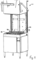
Figs. 1-2 show an exemplary warewash machine; -
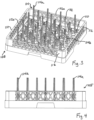
Figs. 3-12 show an exemplary ware rack system for lightweight wares; and -
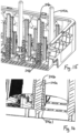
Figs. 13-16 shows another lower ware rack configuration for use in the ware system. - Referring to
Figs. 1-2 , awarewash machine 10 includes a housing 12 (e.g., with support frame and panels) in part defining a treatment chamber 14 with a wash zone 16. The chamber 14 includesfront 18, left 20 and right 22 access openings through which wares can be moved in and out of the chamber for cleaning. One or more upper and/or lower spray arms (e.g., wash arm(s) 23a and rinse arm(s) 23b having respective wash nozzles and rinse nozzles) are disposed above and/or below the wash zone. The spray arms are configured to spray liquid toward the wash zone 16. In a typical machine, bothwash spray arms 23a andrinse spray arms 23b may be provided, with the wash spray arms fed by a pump that recirculates liquid from a collection sump ortank 26 below the wash zone, and the rinse spray arms fed by a pump (or line pressure) that delivers hot water from ahot water booster 98. The arms may, for example, be rotating arms and/or fixed arms. - A multi-sided hood assembly 30 includes
movable front 32, left 36 and right 38 wall sections (e.g., forming a box-like hood structure that is open at the bottom) and the hood assembly may or may not have a moving top wall section and back wall section. The wall sections move together as a unit, such that the multi-sided hood assembly is movable (per arrow 42) between a lowered closed position for washing and a raised open position (e.g., perFig. 1 ) for inlet and outlet of wares. When the multi-sided hood assembly is in the closed position, the hood assembly closes thefront 18, left 20 and right 22 access openings so that cleaning sprays within the chamber will be contained during ware cleaning. When the multi-sided hood assembly is in the open position, thefront 18, left 20 and right 22 access openings are open to permit access to the wash zone for inlet and egress of wares. A pivot handle 44 may be provided to facilitate operator movement of the hood assembly 30. - A stationary chamber
rear wall 50 is disposed at the back or rear side of the treatment chamber and, in embodiments in which the hood assembly includes a rear wall section, thewall 50 is at least partly behind the hood rear wall section when the hood is closed. - A
rack track 90 is removably supported at a lower portion of the treatment chamber in a substantially horizontal use orientation by support structure located at both the front and rear of the treatment chamber. By way of example, the support structure may be various internal housing surfaces and/or brackets. The illustratedrack track 90 is of a metal bar or wire form configuration, with upper bar sections aligned to define a rack support surface or rack support plane for a rack containing wares to be cleaned (e.g., dishes, glasses, pots and/or pans etc.). A rearrack slide rail 80 and a forwardrack slide rail 82 are shown here, in positions raised relative to the rack support plane, for guiding the sliding movement of a rack from, for example, into the treatment chamber via the left side access opening 20 for cleaning, and then out of the treatment chamber via the right side access opening 22 after ware cleaning. - Referring to
Figs. 3-12 , a ware rack system for use with lightweight wares is shown and includes alower ware rack 105 with bottom wall 110 andupright side walls 112. A plurality ofpegs 114 extend upward from the bottom wall 110, and at least some of thepegs 114 aretall pegs 114a that extend upward to place the upper ends of the pegs higher than theupper edges 112a of theside walls 112. Here, some of thepegs 114 areshort pegs 114b that do not have upper ends that are lower than theupper edges 112a of the sidewalls. - In embodiments, the ware rack system also includes an
upper ware rack 107 that can be positioned in an inverted orientation over thelower ware rack 105, such that thebottom wall 120 of the upper ware rack is at the top, and theside walls 122 extend downwardly toward theside walls 112 of the lower ware rack. Theside walls 122 rest on theside walls 112, such that the combined lower and upper ware racks form an enclosure within which lightweight wares are placed for cleaning within a warewash machine (e.g., machine 10), with the lattice structure of both racks enabling cleaning liquids to be sprayed onto the wares within the enclosure. - Here,
upper ware rack 107 is a "flat" rack, such that thebottom wall 120 of the upper ware rack does not have ware holding/positioning projections. Thepegs 114a of thelower rack 105 are sized such that a relatively small gap 130 (e.g., gap dimension of less than 1", gap dimension between ¼" and ¾", or gap dimension between 3/8" and ½") is provided between the upper ends of the pegs and the main support plane 120a defined by the bottom wall of theupper ware rack 107. Thisgap 130 is advantageously used to help stabilize the lightweight wares during cleaning. Specifically, some portion of the wares (e.g., thebottom wall 150 of an invertedplastic cup 152 or other type of open-top container (e.g., a French fry box)) are positioned over thepeg 114, such that, when theupper ware rack 107 is positioned atop thelower ware rack 105, the portion of the ware is effectively loosely trapped between the upper end of thepeg 114 and thebottom wall 120 of the upper ware rack, with only a small amount of vertical movement of the portion of the ware permitted, which in turn limits the movement of the ware itself that can or will take place during cleaning (e.g., a plastic cup or container cannot be flipped upside down or out of the rack system to the liquid sprays of cleaning). - The two ware rack system enclosure with tall pegs also helps stabilize wares even when some portion of the wares are not placed within the
gap 130, because the overall resulting structure still creates limited opportunity for wares to move around. Thus, the system is suited for different size cups and other containers (e.g., fry boxes), and can also be used with other lightweight ware types, such asclam shell packages 153, laying between the rows, all in the same rack system at the same time for simultaneous cleaning. - In one embodiment, the
pegs 114 are integrally formed with the rest of the lower ware rack 105 (e.g., molded together as a plastic monolithic structure), perFig. 6 . In the illustrated embodiment, alltall pegs 114a are substantially the same height. In alternative embodiments, two or more different peg heights may be provided, where both peg heights are above the upper edges of the side walls of the lower rare rack. In the illustrated embodiment, the downwardly facing edges of the upper warerack side walls 122 rest atop the upwardly facing edges of theside walls 112 of the lower ware rack, and provides sufficient stability for the cleaning operation. In other embodiments, alignment features may be provided for the ware racks (e.g., projections at the edges of theside walls 112 fit into openings on the edges of the side walls 122). Attachment/alignment components may also be used (e.g., alignment pins engaged within openings of both sets of side walls). In the illustrated embodiment, thepegs 114a are tapered, with smaller dimension at the top. In other embodiments, the pegs could lack a taper, or other peg shapes could be provided. - Here, the
tall pegs 114a and theshort pegs 114a are arranged in an array defined by a plurality of rows and columns, wherein each row is defined by an alternating sequence of tall pegs and short pegs, and wherein each column is also defined by an alternating sequence of tall pegs and short pegs. However, variations are possible. - In another embodiment, per
Figs. 13-16 , thepegs 114a are add-on components (e.g., of plastic) that are removably attached to the standard, lower height pegs 114b114b of a more standard ware rack. In such case, thepegs 114a define a tubular structure, which may or may not be tapered, with the inner side of the pegs frictionally engaging and held onto thepegs 114b. Thepegs 114a may also include inward projectingfeatures 114a (e.g., threads or other) that help to grip and hold thepegs 114a onto thepegs 114b. Fasteners or clip-latch features may also be provided for attachment of thepegs 114a topegs 114b. In other embodiments, thepegs 114a may be adhered topegs 114b by glues, a melt welds or friction pins. - In some embodiments, a
corresponding peg 114a is attached to eachpeg 114b of a standard peg type ware rack. In other embodiments, acorresponding peg 114a is attached to only some of thepegs 114b (e.g., every other peg in a peg row). - When formed separately and attached, the
tall pegs 114a can be include an internal shape and configuration that matches the external shape and configuration of the rack pegs 114b for engagement therewith (e.g., where the rack pegs 114b have a cross-shape profile in axial end view, the internal cavity of each of thepegs 114a could be of corresponding shape). However, thetall pegs 114a could have an internal shape and configuration that is different than the external shape and configuration of the rack pegs 114b. - In one implementation in which the
tall pegs 114a are separate structures that connect to the shorter rack pegs 114b, thermal properties of therespective pegs tall pegs 114a. In particular, while therack 105 and thetall pegs 114a are both cool (e.g., at or near ambient room temperature), thetall pegs 114a are loosely assembled down onto specific shorter rack pegs 114b in an arrangement as desired for a given use. This step should typically be done outside of the warewash machine. Thetall pegs 114a mate with theshorter pegs 114b with a snug fit that prevents thetall pegs 114a from being easily pressed all the way down onto theshorter pegs 114b. Therack 105 with pegs is then placed into the warewash machine and one or more machine cycles are run so as to heat up both therack 105 and thepegs 114. While therack 105 and thepegs 114 are still hot from the machine cycle(s), thetall pegs 114a are then forced down further onto the rack pegs 114b until thepegs 114a "bottom out". This forcing step could be manual by hand force or could involve, for example, use of a tool, such as a rubber mallet. Because thetall pegs 114a are not solid, thetall pegs 114a expand more than the solid rack pegs 114b. This facilitates the completion of assembly of thetall pegs 114a onto the rack pegs 114b and creates a snug fit when the respective parts cool. A reverse sequence of this process can be used to remove thetall pegs 114a from theshorter pegs 114b (e.g., remove thetall pegs 114a after therack 105 and pegs have been heated by one or more machine cycles). - It is to be clearly understood that the above description is intended by way of illustration and example only, is not intended to be taken by way of limitation, and that other changes and modifications are possible.
Claims (15)
- A ware rack system for holding lightweight wares during cleaning in a warewash machine, comprising:- a lower ware rack including a bottom wall, upright side walls and a plurality of pegs extending upward from the bottom wall, wherein a multiplicity of the pegs are tall pegs that have upper ends that are located higher than upper edges of the upright side walls.
- The ware rack system of claim 1, further comprising:- an upper ware rack positioned in an inverted manner over the lower ware rack, wherein the upper ware rack includes a bottom wall and side walls, the side walls of the upper ware rack resting on the side walls of the lower ware rack.
- The ware rack system of claim 2,
wherein the bottom wall of the upper ware rack defines a main support plane, and the main support plane is spaced from the upper ends of the tall pegs by respective vertical gaps. - The ware rack system of claim 3,wherein at least some of the vertical gaps are less than 2.54 cm (one inch) in height; and/orwherein at least some of the vertical gaps are between 0.635 cm and 1.905 cm (¼" and ¾") in in height.
- The ware rack system of claim 3 or 4, further comprising:- a plastic ware item having a portion that is positioned in one of the vertical gaps.
- The ware rack system of claim 5,
wherein the plastic ware item is an inverted plastic cup or another inverted plastic container. - The ware rack system of one of claims 1 to 6,
wherein at least some of the pegs are short pegs having upper ends that are located lower than upper edges of the upright side walls. - The ware rack system of claim 7,
wherein at least some of the tall pegs are removably connected or fixedly connected onto short pegs of the lower ware rack. - The ware rack system of claim 8 or 9,
wherein the tall pegs and the short pegs are integrally molded to be unitary with the bottom wall and the upright side walls. - The ware rack system of one of claims 1 to 9,
wherein the tall pegs and the short pegs are arranged in an array defined by a plurality of rows and columns, wherein each row is defined by an alternating sequence of tall pegs and short pegs, wherein each column is defined by an alternating sequence of tall pegs and short pegs. - The ware rack system of one of claims 1 to 10 and claim 2,
wherein an alignment structure is provided for positioning of the side walls of the upper ware rack on the side walls of the lower ware rack. - A warewash machine, comprising:- a treatment chamber;- a system for spraying liquids in a treatment zone of the treatment chamber;- the ware rack system of one of claims 1 to 11 positioned in the treatment zone.
- A ware rack system for holding lightweight wares during cleaning in a warewash machine, comprising:- a ware rack including a bottom wall and upright side walls to define a ware receiving space above the bottom wall and within a border defined by the upright walls, the upper side walls having upper edges;- a plurality of first pegs extending upward from the bottom wall, wherein the first pegs have upper ends that are located higher than the upper edges of the upright side walls;- a plurality of second pegs extending upward from the bottom wall, wherein the second pegs have upper ends that are below the upper edges of the upright side walls.
- A method of cleaning a lightweight ware item, comprising:- utilizing a lower rack with a bottom wall and upright peripheral sidewalls, and multiple tall pegs that extend upward beyond upper edges of the upright sidewalls;- placing the lightweight wear item in an inverted manner downward onto the tall peg such that a bottom wall portion of the lightweight wear item sits atop an upper end of the tall peg;- forming a rack system by placing an upper rack with a bottom wall and peripheral sidewalls in an inverted manner down over the lower rack such that the bottom wall portion of the lightweight wear item is captured between the upper end of the tall peg and the bottom wall of the upper rack; and- cleaning the lightweight ware item in a chamber of a warewash machine while the rack system is disposed within the chamber.
- The method of claim 14,
wherein a vertical spacing between the bottom wall of the upper rack and the upper end of the tall peg is less than 2.54 cm (one inch).
Applications Claiming Priority (3)
| Application Number | Priority Date | Filing Date | Title |
|---|---|---|---|
| US202363521762P | 2023-06-19 | 2023-06-19 | |
| US202463616981P | 2024-01-02 | 2024-01-02 | |
| US18/739,891 US20240415367A1 (en) | 2023-06-19 | 2024-06-11 | Warewash rack system and warewasher with associated warewash rack system |
Publications (1)
| Publication Number | Publication Date |
|---|---|
| EP4487748A1 true EP4487748A1 (en) | 2025-01-08 |
Family
ID=91581766
Family Applications (1)
| Application Number | Title | Priority Date | Filing Date |
|---|---|---|---|
| EP24182590.0A Pending EP4487748A1 (en) | 2023-06-19 | 2024-06-17 | Warewash rack system and warewasher with associated warewash rack system |
Country Status (4)
| Country | Link |
|---|---|
| US (1) | US20240415367A1 (en) |
| EP (1) | EP4487748A1 (en) |
| CN (1) | CN119157442A (en) |
| MX (1) | MX2024007365A (en) |
Citations (6)
| Publication number | Priority date | Publication date | Assignee | Title |
|---|---|---|---|---|
| US3141552A (en) * | 1961-06-05 | 1964-07-21 | Jr Ralph Ettlinger | Dishwashing rack |
| DE8437945U1 (en) * | 1984-12-24 | 1989-01-05 | Miele & Cie GmbH & Co, 4830 Gütersloh | Dishwasher for household |
| US5121843A (en) * | 1991-04-29 | 1992-06-16 | Elder Shirley A | Restraining net for dishes |
| US20080156750A1 (en) * | 2006-12-28 | 2008-07-03 | Richardson Margaret A | Dishwasher tine extender |
| US20130220954A1 (en) * | 2012-02-23 | 2013-08-29 | Carol L. Williams | Dish Net and Method of Using |
| DE202018004025U1 (en) * | 2018-08-30 | 2018-11-27 | Michael Klais | Glass holder for dishwashers |
Family Cites Families (2)
| Publication number | Priority date | Publication date | Assignee | Title |
|---|---|---|---|---|
| DE102005061804A1 (en) * | 2005-12-23 | 2007-06-28 | BSH Bosch und Siemens Hausgeräte GmbH | Height-adjustable tableware holder |
| US9408520B2 (en) * | 2012-03-01 | 2016-08-09 | Rosario VACCA | Invertible dishwashing rack and related methods |
-
2024
- 2024-06-11 US US18/739,891 patent/US20240415367A1/en active Pending
- 2024-06-13 MX MX2024007365A patent/MX2024007365A/en unknown
- 2024-06-17 EP EP24182590.0A patent/EP4487748A1/en active Pending
- 2024-06-18 CN CN202410784449.5A patent/CN119157442A/en active Pending
Patent Citations (6)
| Publication number | Priority date | Publication date | Assignee | Title |
|---|---|---|---|---|
| US3141552A (en) * | 1961-06-05 | 1964-07-21 | Jr Ralph Ettlinger | Dishwashing rack |
| DE8437945U1 (en) * | 1984-12-24 | 1989-01-05 | Miele & Cie GmbH & Co, 4830 Gütersloh | Dishwasher for household |
| US5121843A (en) * | 1991-04-29 | 1992-06-16 | Elder Shirley A | Restraining net for dishes |
| US20080156750A1 (en) * | 2006-12-28 | 2008-07-03 | Richardson Margaret A | Dishwasher tine extender |
| US20130220954A1 (en) * | 2012-02-23 | 2013-08-29 | Carol L. Williams | Dish Net and Method of Using |
| DE202018004025U1 (en) * | 2018-08-30 | 2018-11-27 | Michael Klais | Glass holder for dishwashers |
Also Published As
| Publication number | Publication date |
|---|---|
| US20240415367A1 (en) | 2024-12-19 |
| CN119157442A (en) | 2024-12-20 |
| MX2024007365A (en) | 2025-01-09 |
Similar Documents
| Publication | Publication Date | Title |
|---|---|---|
| KR101318361B1 (en) | Dish washer | |
| US20250040785A1 (en) | Warewash rack system and warewasher with associated warewash rack system | |
| EP3773119B1 (en) | Warewash machine with submersible cutlery basket | |
| KR20050105711A (en) | A rack structure of dish washer | |
| CN113455987A (en) | Automatic dish-washing machine | |
| EP3684240A1 (en) | Dishwasher | |
| US11134824B2 (en) | Warewash machine with rack track support member | |
| US12539011B2 (en) | Warewash machine with tray support system and associated rack track with a tray support | |
| US20240415367A1 (en) | Warewash rack system and warewasher with associated warewash rack system | |
| KR101063292B1 (en) | syringe | |
| EP4732743A1 (en) | Warewash rack system and warewasher with associated warewash rack system | |
| CN101573067B (en) | Dishwasher and rack assembly therefor | |
| CN106028898A (en) | dish washer | |
| JP6340544B2 (en) | dishwasher | |
| EP3089647B1 (en) | Dishwasher rack accessory | |
| JP2932272B1 (en) | Bottle cleaning device and bottle holding basket used for it | |
| CN211674116U (en) | A decorative frame installation device for a dishwasher | |
| JP2018019943A (en) | Dishwasher | |
| CN116548881B (en) | Large-scale full-automatic dish washer | |
| JP2508328Y2 (en) | Wagon mounting guide for lifter device | |
| JP2003284671A (en) | Dish washer | |
| US10506908B2 (en) | Batch-type warewasher with energy retaining curtain | |
| US12599282B2 (en) | Dish rack and ware washing system for reusable plastic wares | |
| JP3076228U (en) | Tableware washing machine | |
| KR101296539B1 (en) | Dish washer |
Legal Events
| Date | Code | Title | Description |
|---|---|---|---|
| PUAI | Public reference made under article 153(3) epc to a published international application that has entered the european phase |
Free format text: ORIGINAL CODE: 0009012 |
|
| STAA | Information on the status of an ep patent application or granted ep patent |
Free format text: STATUS: REQUEST FOR EXAMINATION WAS MADE |
|
| 17P | Request for examination filed |
Effective date: 20240617 |
|
| AK | Designated contracting states |
Kind code of ref document: A1 Designated state(s): AL AT BE BG CH CY CZ DE DK EE ES FI FR GB GR HR HU IE IS IT LI LT LU LV MC ME MK MT NL NO PL PT RO RS SE SI SK SM TR |