EP4487745A1 - Blender jar with protrusions introducing asymmetric flow pattern and blender containing the same - Google Patents
Blender jar with protrusions introducing asymmetric flow pattern and blender containing the same Download PDFInfo
- Publication number
- EP4487745A1 EP4487745A1 EP24184592.4A EP24184592A EP4487745A1 EP 4487745 A1 EP4487745 A1 EP 4487745A1 EP 24184592 A EP24184592 A EP 24184592A EP 4487745 A1 EP4487745 A1 EP 4487745A1
- Authority
- EP
- European Patent Office
- Prior art keywords
- protrusion
- wall
- blender jar
- disposed
- blender
- Prior art date
- Legal status (The legal status is an assumption and is not a legal conclusion. Google has not performed a legal analysis and makes no representation as to the accuracy of the status listed.)
- Pending
Links
Images




Classifications
-
- A—HUMAN NECESSITIES
- A47—FURNITURE; DOMESTIC ARTICLES OR APPLIANCES; COFFEE MILLS; SPICE MILLS; SUCTION CLEANERS IN GENERAL
- A47J—KITCHEN EQUIPMENT; COFFEE MILLS; SPICE MILLS; APPARATUS FOR MAKING BEVERAGES
- A47J43/00—Implements for preparing or holding food, not provided for in other groups of this subclass
- A47J43/04—Machines for domestic use not covered elsewhere, e.g. for grinding, mixing, stirring, kneading, emulsifying, whipping or beating foodstuffs, e.g. power-driven
- A47J43/07—Parts or details, e.g. mixing tools, whipping tools
- A47J43/0727—Mixing bowls
-
- A—HUMAN NECESSITIES
- A47—FURNITURE; DOMESTIC ARTICLES OR APPLIANCES; COFFEE MILLS; SPICE MILLS; SUCTION CLEANERS IN GENERAL
- A47J—KITCHEN EQUIPMENT; COFFEE MILLS; SPICE MILLS; APPARATUS FOR MAKING BEVERAGES
- A47J43/00—Implements for preparing or holding food, not provided for in other groups of this subclass
- A47J43/04—Machines for domestic use not covered elsewhere, e.g. for grinding, mixing, stirring, kneading, emulsifying, whipping or beating foodstuffs, e.g. power-driven
- A47J43/07—Parts or details, e.g. mixing tools, whipping tools
-
- A—HUMAN NECESSITIES
- A47—FURNITURE; DOMESTIC ARTICLES OR APPLIANCES; COFFEE MILLS; SPICE MILLS; SUCTION CLEANERS IN GENERAL
- A47J—KITCHEN EQUIPMENT; COFFEE MILLS; SPICE MILLS; APPARATUS FOR MAKING BEVERAGES
- A47J43/00—Implements for preparing or holding food, not provided for in other groups of this subclass
- A47J43/04—Machines for domestic use not covered elsewhere, e.g. for grinding, mixing, stirring, kneading, emulsifying, whipping or beating foodstuffs, e.g. power-driven
- A47J43/046—Machines for domestic use not covered elsewhere, e.g. for grinding, mixing, stirring, kneading, emulsifying, whipping or beating foodstuffs, e.g. power-driven with tools driven from the bottom side
-
- A—HUMAN NECESSITIES
- A47—FURNITURE; DOMESTIC ARTICLES OR APPLIANCES; COFFEE MILLS; SPICE MILLS; SUCTION CLEANERS IN GENERAL
- A47J—KITCHEN EQUIPMENT; COFFEE MILLS; SPICE MILLS; APPARATUS FOR MAKING BEVERAGES
- A47J43/00—Implements for preparing or holding food, not provided for in other groups of this subclass
- A47J43/04—Machines for domestic use not covered elsewhere, e.g. for grinding, mixing, stirring, kneading, emulsifying, whipping or beating foodstuffs, e.g. power-driven
- A47J43/07—Parts or details, e.g. mixing tools, whipping tools
- A47J43/0716—Parts or details, e.g. mixing tools, whipping tools for machines with tools driven from the lower side
- A47J43/0722—Mixing, whipping or cutting tools
-
- A—HUMAN NECESSITIES
- A47—FURNITURE; DOMESTIC ARTICLES OR APPLIANCES; COFFEE MILLS; SPICE MILLS; SUCTION CLEANERS IN GENERAL
- A47J—KITCHEN EQUIPMENT; COFFEE MILLS; SPICE MILLS; APPARATUS FOR MAKING BEVERAGES
- A47J43/00—Implements for preparing or holding food, not provided for in other groups of this subclass
- A47J43/04—Machines for domestic use not covered elsewhere, e.g. for grinding, mixing, stirring, kneading, emulsifying, whipping or beating foodstuffs, e.g. power-driven
- A47J43/07—Parts or details, e.g. mixing tools, whipping tools
- A47J43/08—Driving mechanisms
- A47J43/085—Driving mechanisms for machines with tools driven from the lower side
Definitions
- This invention relates to a blender jar for a small appliance kitchen blender, including one or more protrusions to encourage asymmetric turbulent flow within the blender jar to better comminute the foodstuffs therein.
- Blenders have become even more ubiquitous in the kitchen as well as in numerous retail establishments with the explosion in popularity of various blended drinks.
- a typical blender comprises a motor housing that rotates a mount that cooperates with a rotatable blade disposed on a bottom surface of a blender container (often referred to as a "jar") that preferably creates a turbulent fluid flow from the ingredients loaded into the blender jar as they flow through, and are comminuted within, the rotating blade assembly to mix the contents therein to a desired consistency.
- jar blender container
- the invention relates to a blender jar for operable connection to a blender for comminuting foodstuffs.
- the blender jar can include a base configured to be mounted to a blender, the base comprising a rotatable blade mounted thereto for operable interconnection to a blender.
- the rotatable blade can define a blade radius and a blade path that can be determined by a vertical gap between upper and lower tips of the rotatable blade.
- a wall can extend upwardly from the base having an interior surface that defines an internal blending chamber with an interior surface of the base. The wall can have a terminal edge for receipt of a lid for containing foodstuffs within the blending chamber.
- At least one protrusion can be integrally formed with at least one of the interior surface of the base and the interior surface of the wall.
- the protrusion can extend into the internal blending chamber without extending to the blade radius of the rotatable blade.
- the protrusion can have at least one surface that extends from a lower portion adjacent the base and an upper portion above the blade path of the rotatable blade.
- the interior surface of the wall can define a polygonal surface having at least three vertices.
- the at least one protrusion can be disposed within at least one of the at least three vertices of the interior surface of the wall.
- the at least one protrusion can comprise a plurality of protrusions disposed within a plurality of the at least three vertices with at least one vertex disposed between adjacent protrusions.
- At least one protrusion can comprise a plurality of protrusions disposed within a plurality of the at least three vertices with at least two of the plurality of protrusions disposed within adjacent vertices.
- the blender jar wall can define a generally rectangular cross section having four vertices and the at least one protrusion comprises a plurality of protrusions disposed within oppositely-disposed vertices.
- the wall can also define a generally rectangular cross section having four vertices and the at least one protrusion comprises a plurality of protrusions disposed within adjacent vertices.
- the wall can define a generally rectangular cross section having four vertices and the at least one protrusion comprises a plurality of protrusions disposed within all vertices, excluding one.
- the at least one protrusion can comprise a generally planar surface having a perimeter integrally formed with a portion of the base and a portion of the wall above the blade path.
- the at least one protrusion can comprise a first generally planar surface having a perimeter integrally formed with a portion of the base and a portion of the wall above the blade path and a second generally planar surface having a perimeter integrally formed with a portion of the base and a portion of the wall above the blade path, the first generally planar surface can intersect the second generally planar surface along a midline of the at least one protrusion.
- the at least one protrusion can have an upper portion comprising a generally planar surface that has an edge formed with an upper edge of the first generally planar surface and an upper edge of the second generally planar surface.
- the upper portion of the at least one protrusion can comprise a third generally planar surface and a fourth generally planar surface that are disposed angularly with respect to one another.
- a blender for comminuting foodstuffs can comprise a housing comprising a motor, a controller operably connected to the motor for operating the motor through a plurality of blending modes, a seat defined on an upper portion of the housing, and the seat comprising a bearing having a keyed portion configured to be rotatably driven by the motor.
- a blender jar can comprise a base configured to be mounted on the seat, the base comprising a rotatable blade mounted thereto for operable interconnection to the keyed portion of the seat wherein rotatable motion of the keyed portion will impart rotatable motion to the rotatable blade.
- the rotatable blade can define a blade radius and a blade path, wherein the blade path can be determined by a vertical gap between upper and lower tips of the rotatable blade.
- a wall can extend upwardly from the base that has an interior surface defining an internal blending chamber with an interior surface of the base. The wall can have a terminal edge for receipt of a lid for containing foodstuffs within the blending chamber.
- the blender jar associated with the blender as described herein can include the various surfaces and topographical features of the at least one protrusion as previously described.
- aspects of the present invention relate to a blender jar having one or more protrusions arranged and configured to introduce asymmetric flow patterns within the blender jar.
- direction terms such as “upper,” “lower,” “right,” “left,” “rear,” “front,” “vertical,” “horizontal,” and derivatives thereof, if any, shall relate to the invention as oriented in FIG. 1 from the perspective of a user looking at the front of the blender.
- aspects of the present invention may assume various alternative orientations, except where expressly specified to the contrary.
- a blender 10 comprising a housing 12 and a blender jar 14.
- the housing 12 can be any well-known blender housing as would be known to one skilled in the art and typically comprises a control panel 16, which is not required if the blender 10 is to be operated remotely, for providing signals to a motor internal to the housing 12 that can provide rotational driving movement to a bearing (not shown) that, in turn, can be operably interconnected via an upper seat portion 18 of the housing 12 to a corresponding component of the blender jar 14.
- a control panel 16 which is not required if the blender 10 is to be operated remotely, for providing signals to a motor internal to the housing 12 that can provide rotational driving movement to a bearing (not shown) that, in turn, can be operably interconnected via an upper seat portion 18 of the housing 12 to a corresponding component of the blender jar 14.
- the particular components of the housing 12 shown in the drawings should not be construed as limiting on the scope of the invention contemplated herein, for any number of components that can operate as the housing 12 of the blender 10 would be apparent to one skilled in the art.
- the blender jar 14 generally comprises a base portion 20, and an upstanding wall 22, and a lid 24.
- the base portion 20 of the blender jar 14 typically includes structural components sufficient to mount to the upper seat 18 of the housing 12.
- the particular structural components for mounting the base portion 20 to the upper seat 18 are not germane to the invention and many suitable examples would be known to one skilled in the art.
- the upstanding wall 22 typically has a lower portion having a geometrical perimeter that corresponds with a perimeter of the base portion 20 and extends upwardly therefrom.
- the particular example of the upstanding wall 22 shown in Figure 1 should not be limited as limiting to the scope of the invention.
- the upstanding wall 22 may not have a common cross-section across its height and the perimeter of an interior surface of the upstanding wall 22 may change in shape as it extends upwardly.
- a perimeter of the upstanding wall 22 may be circular adjacent to the upper seat 18 of the housing, but may change to have a different polygonal shape as the upstanding wall 22 extends upwardly from the base portion 20 of the blender jar 14.
- An upper edge of the upstanding wall 22 typically includes a pouring spout 28, the function thereof would be apparent to one skilled in the art as being for pouring blended foodstuffs out of the interior of the blender jar 14.
- the lid 24 typically has a perimeter configured to be sealingly engaged with an upper edge of the upstanding wall 22, including the pouring spout 28, to prevent materials within the blender jar 14 from escaping during blending operations by the blender 10.
- the lid 24 typically has an access hole 30 for providing additional foodstuffs to the interior of the blender jar 14 without needing to disengage the lid 24 from the upper edge of the upstanding wall 22, as well as an access hole plug 32 adapted to sealingly fit within the access hole 30 also to prevent materials within the blender jar 14 from escaping during blending operations. It will be understood that the particular embodiment of the lid 24 shown in the drawings is by example only and should not be construed as limiting on the scope of the invention.
- the base portion 20 of the blender jar 14 contains a rotatable blade 34.
- the rotatable blade 34 typically has a suitable structure, such as a keyed opening or protrusion, configured to receive a mating component on the housing 12 that is operably interconnected to the motor therein (not shown).
- a suitable structure such as a keyed opening or protrusion
- the blender jar 14 is suitably placed atop the housing 12, rotational motion created by the motor within the housing 12 is imparted through these mating components to provide a suitable rotational drive to the rotatable blade 34.
- the particular embodiment of the rotatable blade shown in the drawings should also not be construed as limiting upon the scope of the invention, as any suitable blade component could easily be substituted without departing from the scope of this invention.
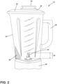
- the various blade subcomponents of the rotatable blade 34 can have varying heights and angles so as to define a vertical height of the rotatable blade, referred to in Figure 2 with reference numeral 36 and the term "blade path.”
- a protrusion 38 is provided within the interior of the blender jar 14. It will be understood that to one skilled in the art, that the protrusion 38 can be provided singularly within the blender jar 14 or as a plurality of protrusions 38 spaced at regular or irregular intervals within the interior of the blender jar 14.
- the protrusion 38 can have any number of geometric configurations and still be contemplated within the scope of the invention described herein.
- the triangular shape of the protrusion 38 shown in the drawings, and in Figures 1 , 2 , and 3A-3D in particular, are shown by example only and the particular shape used for the illustrative embodiment in the drawings should not be construed as limiting the scope of the invention described herein.
- the protrusion 38 is configured to create an obstacle adjacent the rotatable blade 34 to preferably redirect foodstuffs being blended in an asymmetric manner and to provide an interruption of laminar flow that may be formed within the interior of the blender jar 14.
- the protrusion 38 can have a perimeter integrally formed with at least one of the interior surfaces of the base 20 and the upstanding wall 22.
- a lower portion of the protrusion 38 is preferably formed adjacent to, or integral with, the base portion 20 of the blender jar 14 and extends laterally inwardly from the upstanding wall 22 a distance sufficient to provide an interruption to the flow within the blender jar 14 but not to interfere with, or contact, the physical components of the rotatable blade 34.
- the lateral extent to which the protrusion 38 extends inwardly from the interior surface of the upstanding wall 22 can vary along the height of the protrusion 38. In one embodiment of the invention, the height of the protrusion 38 extends vertically above the height defined by the blade path 36 of the rotatable blade 34.
- FIGS 3A-3D various embodiments of the invention are shown wherein one or more protrusions 38 are arranged in various fashions with respect to the base portion 20 and the upstanding wall 22 of the blender jar 14.
- the orientation of Figures 3A-3D is a top plan view looking down into the interior of the blender jar 14 with the lid 24 removed. In this manner the perimeter geometry of the upstanding wall 22 is shown with respect to an upper edge thereof. It will be understood to one skilled in the art that the cross-section of the upstanding wall 22 can change throughout its height.
- the upstanding wall 22 is shown to have a generally curved polygonal shape having four vertices and four sides.
- the particular cross-sectional shape of the upstanding wall 22 can take on a myriad of geometrical or polygonal shapes without departing from the scope of the invention. Indeed, additional or fewer vertices and sides, including zero vertices for a circular or major or minor vertices for an elliptical configuration, can be provided in alternate configurations of the upstanding wall 22 without departing from the scope of the invention.
- the embodiment of the blender jar 14 shown in the drawings also includes one or more ribs 40 extending at least a portion of the height of the upstanding wall 22. It will also be understood by one skilled in the art that the ribs 40 can be provided in additional or fewer numbers, including zero, without departing from the scope of the invention.
- Figure 3A shows a single protrusion 38 disposed generally within one vertex of the particular polygonal shape shown for the upstanding wall 22.
- Figure 3B shows a pair of protrusions 38 disposed in opposite vertices of the particular polygonal shape shown for the upstanding wall 22.
- Figure 3C shows a pair of protrusions 38 disposed in adjacent vertices of the particular polygonal shape shown for the upstanding wall 22.
- Figure 3D shows three protrusions 38 disposed within three of the four vertices shown in the particular polygonal shape shown for the upstanding wall 22.
- FIGS 4A-4D a cutaway portion of the blender jar 14 showing a portion of the base portion 20 in the upstanding wall 22 thereof is shown in each of these drawings.
- the rotatable blade 34 has been removed so that the protrusion 38 can be more clearly illustrated in Figures 4A-4D .
- the protrusion 38 in the example embodiments shown in Figures 4A-4D , is shown having a perimetrical edge intricately formed with a portion of the base portion 20 and a portion of the upstanding wall 22 to form a three-dimensional intrusion into the interior of the blender jar 14.
- the protrusion 38 is shown as a generally convex member having a curved outer surface that extends into the interior of the blender jar 14.
- the protrusion 38 can also have a planar outer surface that is bordered by intersecting a portion of the upstanding wall 22 and the base portion 20 forming essentially a polygonal shape.
- Figure 4B shows an alternative embodiment of the protrusion 38 formed by a first surface 42 and a second surface 44 each formed as a generally convex or generally planar surface and is integrally formed with a portion of the upstanding wall 22 and the base portion 20.
- the first surface 42 and second surface 44 are angularly disposed with respect to one another, preferably along a midline 46 of the protrusion 38.
- the protrusion 38 is also formed with a first surface 42 and a second surface 44 also angularly-disposed to one another, preferably along a midline 46 of the protrusion 38.
- the upper portion of the protrusion 38 is formed by a third surface 48 and a fourth surface 50.
- the first surface is angularly disposed with respect to the second surface 44, the third surface 48, and the fourth surface 50.
- the first and third surfaces 42 and 48 are preferably angularly disposed with respect to the second and fourth surfaces 44 and 50, preferably along the midline 46 of the protrusion 38.
- the first surface 42 is preferably angularly disposed with respect to the third surface 48 across a generally lateral line 52 and the second surface 44 is preferably angularly disposed with respect to the fourth surface 50 across the lateral line 52.
- Figure 4D is an embodiment similar to that shown in Figure 4C but that the lateral line 52 is disposed generally higher than the embodiment shown in Figure 4C such that the angular disposition between the surfaces comprising the protrusion 38 can be varied.
- the surfaces 48 and 50 can be disposed at or above the blade path.
- the blender jar 14 is shown in operation with a pair of schematic mixture arrows 54 showing an example direction of blending typically created by the motor of the housing 12 when the rotatable blade 34 is rotated during any number of blending modes.
- the typical goal of most blending operations is to drive the foodstuffs being blended and comminuted within the blender jar 14 in a rotational fashion such that foodstuffs are drawn downwardly toward the rotatable blades 34 within the blender jar 14.
- the protrusions 38 serve to serve multiple functions within the blender jar 14.
- a lower portion of the protrusion 38 serves to restrict the area adjacent the rotatable blade 34 to direct foodstuffs within the interior of the blender jar 14 toward the rotatable blade 34.
- food particles 56 can be shown impinging upon the exterior surfaces of the protrusion 38 and being directed in an upwardly direction so that they can be later drawn back downwardly by the rotatable blade 34 and further blended and comminuted and preventing eddies or pockets of foodstuffs within the interior of the blender jar 14 that can prevent those foodstuffs from being sufficiently comminuted.
- the protrusion 38 serves to disrupt laminar flow within the blender jar 34 and encourage turbulence within the foodstuffs being blended so that more consistent mixing and blending can be obtained.
- a blender jar for operable connection to a blender for comminuting foodstuffs comprising a base configured to be mounted to a blender, the base comprising a rotatable blade mounted thereto for operable interconnection to a blender, the rotatable blade defining a blade radius and a blade path, the blade path determined by a vertical gap between upper and lower tips of the rotatable blade, a wall extending upwardly from the base having an interior surface defining an internal blending chamber with an interior surface of the base, the wall having a terminal edge for receipt of a lid for containing foodstuffs within the blending chamber, and at least one protrusion integrally formed with at least one of the interior surface of the base and the interior surface of the wall, the protrusion extending into the internal blending chamber without extending to the blade radius of the rotatable blade, the protrusion having at least one surface that extends from a lower portion adjacent the base and an upper portion above the blade path of the rotatable blade.
- the at least one protrusion comprises a plurality of protrusions disposed within a plurality of the at least three vertices with at least one vertex disposed between adjacent protrusions.
- the at least one protrusion comprises a plurality of protrusions disposed within a plurality of the at least three vertices with at least two of the plurality of protrusions disposed within adjacent vertices.
- the blender jar of any of the preceding clauses wherein the wall defines a generally rectangular cross section having four vertices and the at least one protrusion comprises a plurality of protrusions disposed within oppositely-disposed vertices.
- the blender jar of any of the preceding clauses wherein the wall defines a generally rectangular cross section having four vertices and the at least one protrusion comprises a plurality of protrusions disposed within adjacent vertices.
- the at least one protrusion comprises a generally planar surface having a perimeter integrally formed with a portion of the base and a portion of the wall above the blade path.
- the at least one protrusion comprises a first generally planar surface having a perimeter integrally formed with a portion of the base and a portion of the wall above the blade path and a second generally planar surface having a perimeter integrally formed with a portion of the base and a portion of the wall above the blade path, the first generally planar surface intersecting the second generally planar surface along a midline of the at least one protrusion.
- the at least one protrusion has an upper portion comprising a generally planar surface that has an edge formed with an upper edge of the first generally planar surface and an upper edge of the second generally planar surface.
- the upper portion of the at least one protrusion comprises a third generally planar surface and a fourth generally planar surface that are disposed angularly with respect to one another.
- a blender for comminuting foodstuffs comprising a housing comprising a motor, a controller operably connected to the motor for operating the motor through a plurality of blending modes, a seat defined on an upper portion of the housing, the seat comprising a bearing having a keyed portion configured to be rotatably driven by the motor, a blender jar comprising a base configured to be mounted on the seat, the base comprising a rotatable blade mounted thereto for operable interconnection to the keyed portion of the seat wherein rotatable motion of the keyed portion will impart rotatable motion to the rotatable blade, the rotatable blade defining a blade radius and a blade path, the blade path determined by a vertical gap between upper and lower tips of the rotatable blade, a wall extending upwardly from the base having an interior surface defining an internal blending chamber with an interior surface of the base, the wall having a terminal edge for receipt of a lid for containing foodstuffs within the blending chamber, and
- the at least one protrusion comprises a generally planar surface having a perimeter integrally formed with a portion of the base and a portion of the wall above the blade path.
- the at least one protrusion comprises a first generally planar surface having a perimeter integrally formed with a portion of the base and a portion of the wall above the blade path and a second generally planar surface having a perimeter integrally formed with a portion of the base and a portion of the wall above the blade path, the first generally planar surface intersecting the second generally planar surface along a midline of the at least one protrusion.
- the at least one protrusion has an upper portion comprising a generally planar surface that has an edge formed with an upper edge of the first generally planar surface and an upper edge of the second generally planar surface.
- the blender of any of the preceding clauses wherein the upper portion of the at least one protrusion comprises a third generally planar surface and a fourth generally planar surface that are disposed angularly with respect to one another.
Landscapes
- Engineering & Computer Science (AREA)
- Mechanical Engineering (AREA)
- Food Science & Technology (AREA)
- Food-Manufacturing Devices (AREA)
Abstract
Description
- This invention relates to a blender jar for a small appliance kitchen blender, including one or more protrusions to encourage asymmetric turbulent flow within the blender jar to better comminute the foodstuffs therein.
- Blenders have become even more ubiquitous in the kitchen as well as in numerous retail establishments with the explosion in popularity of various blended drinks. A typical blender comprises a motor housing that rotates a mount that cooperates with a rotatable blade disposed on a bottom surface of a blender container (often referred to as a "jar") that preferably creates a turbulent fluid flow from the ingredients loaded into the blender jar as they flow through, and are comminuted within, the rotating blade assembly to mix the contents therein to a desired consistency.
- When blending liquids or relatively soft solids like yogurt or ice cream, blending these items generally produces a desirable result. However, when using ice or any of the numerous other foodstuffs typically blended into drinks (e.g., fruits, vegetables, candy, vitamins, supplements, and the like), it is important to distribute the comminuted solids as evenly as possible within the blended product.
- Depending upon the structures inside the blender jar (or the lack thereof), small eddies or pockets of unblended or less-blended food stuffs can collect, typically in a location outside of the reach of the rotatable blade. When this occurs, the user must stop operation of the blender, and safely scrape the collected foodstuffs back toward the blade and attempt to re-blend the foodstuffs until a satisfactory result occurs, causing frustration and increasing the time to prepare a satisfactory blended food product (a consideration in the home, but critically important in a retail establishment).
- In one aspect of the invention, the invention relates to a blender jar for operable connection to a blender for comminuting foodstuffs. The blender jar can include a base configured to be mounted to a blender, the base comprising a rotatable blade mounted thereto for operable interconnection to a blender. The rotatable blade can define a blade radius and a blade path that can be determined by a vertical gap between upper and lower tips of the rotatable blade. A wall can extend upwardly from the base having an interior surface that defines an internal blending chamber with an interior surface of the base. The wall can have a terminal edge for receipt of a lid for containing foodstuffs within the blending chamber.
- At least one protrusion can be integrally formed with at least one of the interior surface of the base and the interior surface of the wall. The protrusion can extend into the internal blending chamber without extending to the blade radius of the rotatable blade. The protrusion can have at least one surface that extends from a lower portion adjacent the base and an upper portion above the blade path of the rotatable blade.
- Various alternative embodiments of the invention are contemplated without departing from the scope of the invention. For example, the interior surface of the wall can define a polygonal surface having at least three vertices. The at least one protrusion can be disposed within at least one of the at least three vertices of the interior surface of the wall. The at least one protrusion can comprise a plurality of protrusions disposed within a plurality of the at least three vertices with at least one vertex disposed between adjacent protrusions. At least one protrusion can comprise a plurality of protrusions disposed within a plurality of the at least three vertices with at least two of the plurality of protrusions disposed within adjacent vertices.
- The blender jar wall can define a generally rectangular cross section having four vertices and the at least one protrusion comprises a plurality of protrusions disposed within oppositely-disposed vertices. The wall can also define a generally rectangular cross section having four vertices and the at least one protrusion comprises a plurality of protrusions disposed within adjacent vertices. The wall can define a generally rectangular cross section having four vertices and the at least one protrusion comprises a plurality of protrusions disposed within all vertices, excluding one.
- Various embodiments of the surfaces comprising the at least one protrusion are also contemplated without departing from the scope of the invention. The at least one protrusion can comprise a generally planar surface having a perimeter integrally formed with a portion of the base and a portion of the wall above the blade path. The at least one protrusion can comprise a first generally planar surface having a perimeter integrally formed with a portion of the base and a portion of the wall above the blade path and a second generally planar surface having a perimeter integrally formed with a portion of the base and a portion of the wall above the blade path, the first generally planar surface can intersect the second generally planar surface along a midline of the at least one protrusion. The at least one protrusion can have an upper portion comprising a generally planar surface that has an edge formed with an upper edge of the first generally planar surface and an upper edge of the second generally planar surface. The upper portion of the at least one protrusion can comprise a third generally planar surface and a fourth generally planar surface that are disposed angularly with respect to one another.
- In another aspect of the invention, the blender jar described herein can be included with components of a blender. For example, a blender for comminuting foodstuffs can comprise a housing comprising a motor, a controller operably connected to the motor for operating the motor through a plurality of blending modes, a seat defined on an upper portion of the housing, and the seat comprising a bearing having a keyed portion configured to be rotatably driven by the motor. A blender jar can comprise a base configured to be mounted on the seat, the base comprising a rotatable blade mounted thereto for operable interconnection to the keyed portion of the seat wherein rotatable motion of the keyed portion will impart rotatable motion to the rotatable blade. The rotatable blade can define a blade radius and a blade path, wherein the blade path can be determined by a vertical gap between upper and lower tips of the rotatable blade. A wall can extend upwardly from the base that has an interior surface defining an internal blending chamber with an interior surface of the base. The wall can have a terminal edge for receipt of a lid for containing foodstuffs within the blending chamber. The blender jar associated with the blender as described herein can include the various surfaces and topographical features of the at least one protrusion as previously described.
- In the drawings:
-
Figure 1 is a front elevational view of a blender comprising a motor housing with a blender jar mounted thereon having a rotatable blade assembly operably connected to the motor housing for comminuting foodstuffs within the blender jar. -
Figure 2 is a front elevational view of the blender jar shown inFigure 1 illustrating a protrusion disposed within the blender jar extending above a blade path defined between upper and lower vertical limits of the rotatable blade assembly disposed within the blender jar. -
Figure 3A is a top plan view looking down into the blender jar ofFigures 1-2 with the lid removed showing a protrusion disposed within the blender jar at a vertex of a pair of sides of the blender jar. -
Figure 3B is a top plan view in a similar orientation as that shown inFigure 3A in which a plurality of protrusions are shown disposed within the blender jar in an opposite orientation from one another. -
Figure 3C is a top plan view in a similar orientation as that shown inFigure 3A in which a plurality of protrusions are shown in an adjacent orientation along a common side of the blender jar. -
Figure 3D is a top plan view in a similar orientation as that shown inFigure 3A in which a plurality of protrusions are shown disposed within all vertices, except for one, of the blender jar. -
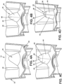
Figure 4A is a cross-sectional view of a base portion of the blender jar showing a first embodiment of the protrusion having a first generally planar surface configuration. -
Figure 4B is a cross-sectional view of a base portion of the blender jar showing a second embodiment of the protrusion having pair of angularly-closed surfaces having a common side. -
Figure 4C is a cross-sectional view of a base portion of the blender jar showing a third embodiment of the protrusion having a pair of angularly disposed surfaces having a common side and an intermediate angular portion. -
Figure 4D is a cross-sectional view of a base portion of the blender jar showing a fourth embodiment of the protrusion having a pair of angularly disposed surfaces having a common side and an upper angular portion formed by a pair of angularly-disposed surfaces. -
Figure 5 is a front elevational view of the blender jar shown inFigures 1-2 showing an example embodiment of the protrusion according to the invention and schematic arrows showing a preferred path of the comminuted foodstuffs as the rotatable blade assembly moves the foodstuffs being blended in the blender jar in an asymmetric fashion. -
Figure 6 is an enlarged schematic portion of the protrusion shown inFigure 5 , illustrating generally random impingements of blended foodstuffs are redirected by impact upon the protrusion. - Aspects of the present invention relate to a blender jar having one or more protrusions arranged and configured to introduce asymmetric flow patterns within the blender jar. For purposes of description related to the figures, direction terms such as "upper," "lower," "right," "left," "rear," "front," "vertical," "horizontal," and derivatives thereof, if any, shall relate to the invention as oriented in
FIG. 1 from the perspective of a user looking at the front of the blender. However, it is to be understood that aspects of the present invention may assume various alternative orientations, except where expressly specified to the contrary. - Turning now to the drawings into
Figure 1 in particular, ablender 10 is shown comprising ahousing 12 and ablender jar 14. - The
housing 12 can be any well-known blender housing as would be known to one skilled in the art and typically comprises acontrol panel 16, which is not required if theblender 10 is to be operated remotely, for providing signals to a motor internal to thehousing 12 that can provide rotational driving movement to a bearing (not shown) that, in turn, can be operably interconnected via anupper seat portion 18 of thehousing 12 to a corresponding component of theblender jar 14. The particular components of thehousing 12 shown in the drawings should not be construed as limiting on the scope of the invention contemplated herein, for any number of components that can operate as thehousing 12 of theblender 10 would be apparent to one skilled in the art. - Turning to
Figures 1-2 , the particular embodiment of theblender jar 14 will now be described. Theblender jar 14 generally comprises abase portion 20, and anupstanding wall 22, and alid 24. Thebase portion 20 of theblender jar 14 typically includes structural components sufficient to mount to theupper seat 18 of thehousing 12. The particular structural components for mounting thebase portion 20 to theupper seat 18 are not germane to the invention and many suitable examples would be known to one skilled in the art. Theupstanding wall 22 typically has a lower portion having a geometrical perimeter that corresponds with a perimeter of thebase portion 20 and extends upwardly therefrom. The particular example of theupstanding wall 22 shown inFigure 1 should not be limited as limiting to the scope of the invention. It would be known to one skilled in the art that theupstanding wall 22 may not have a common cross-section across its height and the perimeter of an interior surface of theupstanding wall 22 may change in shape as it extends upwardly. In the example shown herein, a perimeter of theupstanding wall 22 may be circular adjacent to theupper seat 18 of the housing, but may change to have a different polygonal shape as theupstanding wall 22 extends upwardly from thebase portion 20 of theblender jar 14. An upper edge of theupstanding wall 22 typically includes a pouringspout 28, the function thereof would be apparent to one skilled in the art as being for pouring blended foodstuffs out of the interior of theblender jar 14. Thelid 24 typically has a perimeter configured to be sealingly engaged with an upper edge of theupstanding wall 22, including the pouringspout 28, to prevent materials within theblender jar 14 from escaping during blending operations by theblender 10. Thelid 24 typically has anaccess hole 30 for providing additional foodstuffs to the interior of theblender jar 14 without needing to disengage thelid 24 from the upper edge of theupstanding wall 22, as well as anaccess hole plug 32 adapted to sealingly fit within theaccess hole 30 also to prevent materials within theblender jar 14 from escaping during blending operations. It will be understood that the particular embodiment of thelid 24 shown in the drawings is by example only and should not be construed as limiting on the scope of the invention. - As would be apparent to one skilled in the art, the
base portion 20 of theblender jar 14 contains arotatable blade 34. Therotatable blade 34 typically has a suitable structure, such as a keyed opening or protrusion, configured to receive a mating component on thehousing 12 that is operably interconnected to the motor therein (not shown). Once theblender jar 14 is suitably placed atop thehousing 12, rotational motion created by the motor within thehousing 12 is imparted through these mating components to provide a suitable rotational drive to therotatable blade 34. The particular embodiment of the rotatable blade shown in the drawings should also not be construed as limiting upon the scope of the invention, as any suitable blade component could easily be substituted without departing from the scope of this invention. It should be noted that, with reference toFigure 2 , the various blade subcomponents of therotatable blade 34 can have varying heights and angles so as to define a vertical height of the rotatable blade, referred to inFigure 2 withreference numeral 36 and the term "blade path." - In one aspect of the invention, a
protrusion 38 is provided within the interior of theblender jar 14. It will be understood that to one skilled in the art, that theprotrusion 38 can be provided singularly within theblender jar 14 or as a plurality ofprotrusions 38 spaced at regular or irregular intervals within the interior of theblender jar 14. - The
protrusion 38 can have any number of geometric configurations and still be contemplated within the scope of the invention described herein. The triangular shape of theprotrusion 38 shown in the drawings, and inFigures 1 ,2 , and3A-3D in particular, are shown by example only and the particular shape used for the illustrative embodiment in the drawings should not be construed as limiting the scope of the invention described herein. Theprotrusion 38 is configured to create an obstacle adjacent therotatable blade 34 to preferably redirect foodstuffs being blended in an asymmetric manner and to provide an interruption of laminar flow that may be formed within the interior of theblender jar 14. Theprotrusion 38 can have a perimeter integrally formed with at least one of the interior surfaces of thebase 20 and theupstanding wall 22. A lower portion of theprotrusion 38 is preferably formed adjacent to, or integral with, thebase portion 20 of theblender jar 14 and extends laterally inwardly from the upstanding wall 22 a distance sufficient to provide an interruption to the flow within theblender jar 14 but not to interfere with, or contact, the physical components of therotatable blade 34. It will be understood that the lateral extent to which theprotrusion 38 extends inwardly from the interior surface of theupstanding wall 22 can vary along the height of theprotrusion 38. In one embodiment of the invention, the height of theprotrusion 38 extends vertically above the height defined by theblade path 36 of therotatable blade 34. - Turning to
Figures 3A-3D , various embodiments of the invention are shown wherein one ormore protrusions 38 are arranged in various fashions with respect to thebase portion 20 and theupstanding wall 22 of theblender jar 14. The orientation ofFigures 3A-3D is a top plan view looking down into the interior of theblender jar 14 with thelid 24 removed. In this manner the perimeter geometry of theupstanding wall 22 is shown with respect to an upper edge thereof. It will be understood to one skilled in the art that the cross-section of theupstanding wall 22 can change throughout its height. In theexample blender jar 14 shown in the drawings, theupstanding wall 22 is shown to have a generally curved polygonal shape having four vertices and four sides. One skilled in the art will understand that the particular cross-sectional shape of theupstanding wall 22 can take on a myriad of geometrical or polygonal shapes without departing from the scope of the invention. Indeed, additional or fewer vertices and sides, including zero vertices for a circular or major or minor vertices for an elliptical configuration, can be provided in alternate configurations of theupstanding wall 22 without departing from the scope of the invention. In addition, the embodiment of theblender jar 14 shown in the drawings also includes one ormore ribs 40 extending at least a portion of the height of theupstanding wall 22. It will also be understood by one skilled in the art that theribs 40 can be provided in additional or fewer numbers, including zero, without departing from the scope of the invention. -
Figure 3A shows asingle protrusion 38 disposed generally within one vertex of the particular polygonal shape shown for theupstanding wall 22.Figure 3B shows a pair ofprotrusions 38 disposed in opposite vertices of the particular polygonal shape shown for theupstanding wall 22.Figure 3C shows a pair ofprotrusions 38 disposed in adjacent vertices of the particular polygonal shape shown for theupstanding wall 22.Figure 3D shows threeprotrusions 38 disposed within three of the four vertices shown in the particular polygonal shape shown for theupstanding wall 22. For other polygonal shapes having a different number of sides and vertices than four for theupstanding wall 22, it will be understood by one skilled in the art that the invention contemplates placing one or more of theprotrusions 38 in any combination from one to n-1 of the vertices in the particular polygonal shape for alternate embodiments of theupstanding wall 22 without departing from the scope of the invention. - Turning to
Figures 4A-4D , a cutaway portion of theblender jar 14 showing a portion of thebase portion 20 in theupstanding wall 22 thereof is shown in each of these drawings. For purposes of clarity, therotatable blade 34 has been removed so that theprotrusion 38 can be more clearly illustrated inFigures 4A-4D . Theprotrusion 38, in the example embodiments shown inFigures 4A-4D , is shown having a perimetrical edge intricately formed with a portion of thebase portion 20 and a portion of theupstanding wall 22 to form a three-dimensional intrusion into the interior of theblender jar 14. InFigure 4A , theprotrusion 38 is shown as a generally convex member having a curved outer surface that extends into the interior of theblender jar 14. Theprotrusion 38 can also have a planar outer surface that is bordered by intersecting a portion of theupstanding wall 22 and thebase portion 20 forming essentially a polygonal shape.Figure 4B shows an alternative embodiment of theprotrusion 38 formed by afirst surface 42 and asecond surface 44 each formed as a generally convex or generally planar surface and is integrally formed with a portion of theupstanding wall 22 and thebase portion 20. In the embodiment shown inFigure 4B , thefirst surface 42 andsecond surface 44 are angularly disposed with respect to one another, preferably along amidline 46 of theprotrusion 38. In the embodiment shown inFigure 4C , theprotrusion 38 is also formed with afirst surface 42 and asecond surface 44 also angularly-disposed to one another, preferably along amidline 46 of theprotrusion 38. Additionally, in the upper portion of theprotrusion 38 is formed by athird surface 48 and afourth surface 50. As shown in the embodiment ofFigure 4C , the first surface is angularly disposed with respect to thesecond surface 44, thethird surface 48, and thefourth surface 50. The first andthird surfaces fourth surfaces midline 46 of theprotrusion 38. Thefirst surface 42 is preferably angularly disposed with respect to thethird surface 48 across a generallylateral line 52 and thesecond surface 44 is preferably angularly disposed with respect to thefourth surface 50 across thelateral line 52.Figure 4D is an embodiment similar to that shown inFigure 4C but that thelateral line 52 is disposed generally higher than the embodiment shown inFigure 4C such that the angular disposition between the surfaces comprising theprotrusion 38 can be varied. In some instances, thesurfaces - Turning to
Figure 5 , theblender jar 14 is shown in operation with a pair of schematic mixture arrows 54 showing an example direction of blending typically created by the motor of thehousing 12 when therotatable blade 34 is rotated during any number of blending modes. The typical goal of most blending operations, as would be apparent to one skilled in the art, is to drive the foodstuffs being blended and comminuted within theblender jar 14 in a rotational fashion such that foodstuffs are drawn downwardly toward therotatable blades 34 within theblender jar 14. In order to prevent some of the problems mentioned above with the prior art, theprotrusions 38 serve to serve multiple functions within theblender jar 14. First, a lower portion of theprotrusion 38 serves to restrict the area adjacent therotatable blade 34 to direct foodstuffs within the interior of theblender jar 14 toward therotatable blade 34. In addition, as shown inFigure 6 ,food particles 56 can be shown impinging upon the exterior surfaces of theprotrusion 38 and being directed in an upwardly direction so that they can be later drawn back downwardly by therotatable blade 34 and further blended and comminuted and preventing eddies or pockets of foodstuffs within the interior of theblender jar 14 that can prevent those foodstuffs from being sufficiently comminuted. Finally, theprotrusion 38 serves to disrupt laminar flow within theblender jar 34 and encourage turbulence within the foodstuffs being blended so that more consistent mixing and blending can be obtained. - To the extent not already described, the different features and structures of the various embodiments can be used in combination with each other as desired. That one feature may not be illustrated in all of the embodiments is not meant to be construed that it cannot be, but is done for brevity of description. Thus, the various features of the different embodiments can be mixed and matched as desired to form new embodiments, whether or not the new embodiments are expressly described. All combinations or permutations of features described herein are covered by this invention. Further, while the invention has been specifically described in connection with certain specific embodiments thereof, it is to be understood that this is by way of illustration and not of limitation. In addition to the concepts covered by the below claims, the following clauses can also provide the basis for claims in any possible combinations:
- A blender jar for operable connection to a blender for comminuting foodstuffs comprising a base configured to be mounted to a blender, the base comprising a rotatable blade mounted thereto for operable interconnection to a blender, the rotatable blade defining a blade radius and a blade path, the blade path determined by a vertical gap between upper and lower tips of the rotatable blade, a wall extending upwardly from the base having an interior surface defining an internal blending chamber with an interior surface of the base, the wall having a terminal edge for receipt of a lid for containing foodstuffs within the blending chamber, and at least one protrusion integrally formed with at least one of the interior surface of the base and the interior surface of the wall, the protrusion extending into the internal blending chamber without extending to the blade radius of the rotatable blade, the protrusion having at least one surface that extends from a lower portion adjacent the base and an upper portion above the blade path of the rotatable blade.
- The blender jar of the preceding clause wherein the interior surface of the wall defines a polygonal surface having at least three vertices.
- The blender jar of any of the preceding clauses wherein the at least one protrusion is disposed within at least one of the at least three vertices of the interior surface of the wall.
- The blender jar of any of the preceding clauses wherein the at least one protrusion comprises a plurality of protrusions disposed within a plurality of the at least three vertices with at least one vertex disposed between adjacent protrusions.
- The blender jar of any of the preceding clauses wherein the at least one protrusion comprises a plurality of protrusions disposed within a plurality of the at least three vertices with at least two of the plurality of protrusions disposed within adjacent vertices.
- The blender jar of any of the preceding clauses wherein the wall defines a generally rectangular cross section having four vertices and the at least one protrusion comprises a plurality of protrusions disposed within oppositely-disposed vertices.
- The blender jar of any of the preceding clauses wherein the wall defines a generally rectangular cross section having four vertices and the at least one protrusion comprises a plurality of protrusions disposed within adjacent vertices.
- The blender jar of any of the preceding clauses wherein the wall defines a generally rectangular cross section having four vertices and the at least one protrusion comprises a plurality of protrusions disposed within all vertices, excluding one.
- The blender jar of any of the preceding clauses wherein the at least one protrusion comprises a generally planar surface having a perimeter integrally formed with a portion of the base and a portion of the wall above the blade path.
- The blender jar of any of the preceding clauses wherein the at least one protrusion comprises a first generally planar surface having a perimeter integrally formed with a portion of the base and a portion of the wall above the blade path and a second generally planar surface having a perimeter integrally formed with a portion of the base and a portion of the wall above the blade path, the first generally planar surface intersecting the second generally planar surface along a midline of the at least one protrusion.
- The blender jar of any of the preceding clauses wherein the at least one protrusion has an upper portion comprising a generally planar surface that has an edge formed with an upper edge of the first generally planar surface and an upper edge of the second generally planar surface.
- The blender jar of any of the preceding clauses wherein the upper portion of the at least one protrusion comprises a third generally planar surface and a fourth generally planar surface that are disposed angularly with respect to one another.
- A blender for comminuting foodstuffs comprising a housing comprising a motor, a controller operably connected to the motor for operating the motor through a plurality of blending modes, a seat defined on an upper portion of the housing, the seat comprising a bearing having a keyed portion configured to be rotatably driven by the motor, a blender jar comprising a base configured to be mounted on the seat, the base comprising a rotatable blade mounted thereto for operable interconnection to the keyed portion of the seat wherein rotatable motion of the keyed portion will impart rotatable motion to the rotatable blade, the rotatable blade defining a blade radius and a blade path, the blade path determined by a vertical gap between upper and lower tips of the rotatable blade, a wall extending upwardly from the base having an interior surface defining an internal blending chamber with an interior surface of the base, the wall having a terminal edge for receipt of a lid for containing foodstuffs within the blending chamber, and at least one protrusion integrally formed with at least one of the interior surface of the base and the interior surface of the wall, the protrusion extending into the internal blending chamber without extending to the blade radius of the rotatable blade, the protrusion having at least one surface that extends from a lower portion adjacent the base and an upper portion above the blade path of the rotatable blade.
- The blender of the preceding clause wherein the at least one protrusion comprises a generally planar surface having a perimeter integrally formed with a portion of the base and a portion of the wall above the blade path.
- The blender of any of the preceding clauses wherein the at least one protrusion comprises a first generally planar surface having a perimeter integrally formed with a portion of the base and a portion of the wall above the blade path and a second generally planar surface having a perimeter integrally formed with a portion of the base and a portion of the wall above the blade path, the first generally planar surface intersecting the second generally planar surface along a midline of the at least one protrusion.
- The blender of any of the preceding clauses wherein the at least one protrusion has an upper portion comprising a generally planar surface that has an edge formed with an upper edge of the first generally planar surface and an upper edge of the second generally planar surface.
- The blender of any of the preceding clauses wherein the upper portion of the at least one protrusion comprises a third generally planar surface and a fourth generally planar surface that are disposed angularly with respect to one another.
- While the invention has been specifically described in connection with certain specific embodiments thereof, it is to be understood that this is by way of illustration and not of limitation. Reasonable variation and modification are possible within the scope of the forgoing written description and drawings without departing from the scope of the invention which is defined in the appended claims.
Claims (15)
- A blender jar (14) for operable connection to a blender (10) for comminuting foodstuffs, the blender jar (14) comprising:a base (20) configured to be mounted to a blender (10);a rotatable blade (34) mounted on the base (20) for operable interconnection to a blender (10), the rotatable blade (34) defining a blade radius and a blade path (36), the blade path (36) being determined by a vertical gap between upper and lower tips of the rotatable blade (34);a wall (22) extending upwardly from the base (20), the wall (22) having an interior surface defining an internal blending chamber with an interior surface of the base (20); andat least one protrusion (38) integrally formed with at least one of the interior surface of the base (20) and the interior surface of the wall (22), the protrusion (38) extending from a lower portion adjacent the base (20) to an upper portion above the blade path (36) of the rotatable blade (34).
- The blender jar (14) of claim 1 further comprising a lid (24), wherein the wall (22) has a terminal edge for receipt of the lid (24) for containing foodstuffs within the blending chamber,
optionally wherein the terminal edge of the wall (22) includes a pouring spout (28) and the lid (24) has a perimeter configured to be sealingly engaged with the terminal edge of the wall (22), including the pouring spout (28). - The blender jar (14) of claims 1 or 2 wherein the protrusion (38) extends into the internal blending chamber without extending to the blade radius of the rotatable blade (34).
- The blender jar (14) of any one of claims 1 to 3 wherein the interior surface of the wall (22) defines a polygonal surface having at least three vertices and wherein the at least one protrusion (38) is disposed within at least one of the at least three vertices of the interior surface of the wall (22).
- The blender jar (14) of claim 4 wherein the at least one protrusion (38) comprises a plurality of protrusions (38) disposed within a plurality of the at least three vertices.
- The blender jar (14) of claim 5 wherein the protrusions (38) of the plurality of protrusions (38) are disposed within a plurality of the at least three vertices with at least one vertex disposed between adjacent protrusions and/or with at least two of the plurality of protrusions disposed within adjacent vertices.
- The blender jar (14) of any one of claims 4 to 6 wherein the at least one protrusion (38) comprises:a single protrusion (38) disposed within one vertex of the interior surface of the wall (22) ora pair of protrusions (38) disposed within opposite vertices of the interior surface of the wall (22) ora pair of protrusions (38) disposed within adjacent vertices of the interior surface of the wall (22) orthree protrusions (38) disposed within adjacent vertices of the interior surface of the wall (22)optionally wherein the interior surface of the wall (22) defines a polygonal surface having four vertices or more than four vertices.
- The blender jar (14) of any one of claims 4 to 7 wherein the at least one protrusion (38) comprises a plurality of protrusions (38) disposed within oppositely-disposed vertices and/or within adjacent vertices.
- The blender jar (14) of claims 4 to 8, wherein the at least one protrusion (38) comprises a plurality of protrusions (38) disposed within all vertices, excluding one.
- The blender jar (14) of claims 8 or 9, wherein the wall (22) defines a generally square or rectangular cross section having four vertices.
- The blender jar (14) of any one of claims 1 to 10 wherein the at least one protrusion (38) comprises at least one generally planar surface having a perimeter integrally formed with a portion of the base (20) and a portion of the wall (22) above the blade path (36).
- The blender jar (14) of claim 11 wherein the at least one protrusion (38) comprises a first generally planar surface having a perimeter integrally formed with a portion of the base (20) and a portion of the wall (22) above the blade path (36) and a second generally planar surface having a perimeter integrally formed with a portion of the base (20) and a portion of the wall (22) above the blade path (36), the first generally planar surface intersecting the second generally planar surface along a midline of the at least one protrusion (38),optionally wherein the at least one protrusion (38) has an upper portion comprising a generally planar surface that has an edge formed with an upper edge of the first generally planar surface and an upper edge of the second generally planar surface,the upper portion of the at least one protrusion (38) comprising in particular a third generally planar surface and a fourth generally planar surface disposed angularly with respect to one another.
- The blender jar (14) of any one of claims 1 to 12 wherein the at least one protrusion (38) is configured to form a three-dimensional intrusion into the internal blending chamber,
optionally wherein the at least one protrusion (38) is a convex member having a curved outer surface that extends into the internal blending chamber, the protrusion (38) having in particular a planar outer surface bordered by intersecting a portion of the wall (22) and a portion of the base (20). - The blender jar (14) of any one of claims 1 to 13 wherein the at least one protrusion (38) is formed by a first surface (42) and a second surface (44) each formed as a generally convex or generally planar surface and is integrally formed with a portion of the wall (22) and with a portion of the base (20), the first surface (42) and the second surface (44) being angularly disposed with respect to one another, in particular along a midline (46) of the at least one protrusion (38),
optionally wherein in the upper portion of the at least one protrusion (38) a third surface (48) and a fourth surface (50) are formed, the first surface (42) being angularly disposed with respect to the second surface (44), the third surface (48) and the fourth surface (50), the first surface (42) and the third surface (48) being angularly disposed with respect to the second surface (44) and to the fourth surface (50), in particular along a midline (46) of the at least one protrusion (38), the first surface (42) being in particular angularly disposed with respect to the third surface (48) across a generally lateral line (52) and the second surface (44) being in particular angularly disposed with respect to the fourth surface (50) across the lateral line (52). - A blender (10) for comminuting foodstuffs comprising:a housing (12);a motor accommodated in the housing (12);a controller operably connected to the motor for operating the motor through a plurality of blending modes; anda blender jar (14) according to any one of the previous claims,wherein a seat (18) is defined on an upper portion of the housing (12),wherein the seat (18) comprises a keyed portion configured to be rotatably driven by the motor andwherein the rotatable blade (34) is configured for operable interconnection to the keyed portion so that rotatable motion of the keyed portion imparts rotatable motion to the rotatable blade (34).
Applications Claiming Priority (1)
| Application Number | Priority Date | Filing Date | Title |
|---|---|---|---|
| US18/215,363 US20250000302A1 (en) | 2023-06-28 | 2023-06-28 | Blender jar with protrusions introducing asymmetric flow pattern and blender containing the same |
Publications (1)
| Publication Number | Publication Date |
|---|---|
| EP4487745A1 true EP4487745A1 (en) | 2025-01-08 |
Family
ID=91699929
Family Applications (1)
| Application Number | Title | Priority Date | Filing Date |
|---|---|---|---|
| EP24184592.4A Pending EP4487745A1 (en) | 2023-06-28 | 2024-06-26 | Blender jar with protrusions introducing asymmetric flow pattern and blender containing the same |
Country Status (4)
| Country | Link |
|---|---|
| US (1) | US20250000302A1 (en) |
| EP (1) | EP4487745A1 (en) |
| CN (1) | CN119214517A (en) |
| AU (1) | AU2024204003A1 (en) |
Citations (3)
| Publication number | Priority date | Publication date | Assignee | Title |
|---|---|---|---|---|
| US7918601B2 (en) * | 2005-02-04 | 2011-04-05 | Hamilton Beach Brands, Inc. | Dispensing blender jar |
| US20130215707A1 (en) * | 2012-02-21 | 2013-08-22 | Santos | Jar for processing foodstuffs for a blender |
| US20220022693A1 (en) * | 2020-07-27 | 2022-01-27 | Sharkninja Operating Llc | Container for food processing system |
Family Cites Families (6)
| Publication number | Priority date | Publication date | Assignee | Title |
|---|---|---|---|---|
| US8109668B2 (en) * | 2007-03-01 | 2012-02-07 | Hamilton Beach Brands, Inc. | Blender having an invertable jar for compact storage |
| US8403556B2 (en) * | 2011-02-10 | 2013-03-26 | Quanzhou Yida Home Appliance Industry Co., Ltd. | Blender lid safety protection device |
| US8721165B2 (en) * | 2011-09-23 | 2014-05-13 | Whirlpool Corporation | Blender with varying internally and externally shaped container |
| US9814357B2 (en) * | 2013-03-14 | 2017-11-14 | Spectrum Brands, Inc. | Container and blade arrangement for food preparation appliance |
| US9420915B2 (en) * | 2014-04-03 | 2016-08-23 | Blendtec, Inc. | Blending jar with ridges |
| KR102584608B1 (en) * | 2019-05-08 | 2023-10-05 | 엘지전자 주식회사 | A blender |
-
2023
- 2023-06-28 US US18/215,363 patent/US20250000302A1/en active Pending
-
2024
- 2024-06-13 AU AU2024204003A patent/AU2024204003A1/en active Pending
- 2024-06-26 EP EP24184592.4A patent/EP4487745A1/en active Pending
- 2024-06-28 CN CN202410860987.8A patent/CN119214517A/en active Pending
Patent Citations (3)
| Publication number | Priority date | Publication date | Assignee | Title |
|---|---|---|---|---|
| US7918601B2 (en) * | 2005-02-04 | 2011-04-05 | Hamilton Beach Brands, Inc. | Dispensing blender jar |
| US20130215707A1 (en) * | 2012-02-21 | 2013-08-22 | Santos | Jar for processing foodstuffs for a blender |
| US20220022693A1 (en) * | 2020-07-27 | 2022-01-27 | Sharkninja Operating Llc | Container for food processing system |
Also Published As
| Publication number | Publication date |
|---|---|
| CN119214517A (en) | 2024-12-31 |
| AU2024204003A1 (en) | 2025-01-16 |
| US20250000302A1 (en) | 2025-01-02 |
Similar Documents
| Publication | Publication Date | Title |
|---|---|---|
| US9420915B2 (en) | Blending jar with ridges | |
| US8753004B2 (en) | Container for a blender | |
| US12171374B2 (en) | Blender system with rotatable blade assembly | |
| CN113825434B (en) | Stirring apparatus and method | |
| CN1839736B (en) | Stirring bottle | |
| US10849461B2 (en) | Container and blade arrangement for food preparation appliance | |
| US10856697B2 (en) | Blending system | |
| US12336668B2 (en) | Blending system | |
| JP6642956B2 (en) | Disposable container hybrid apparatus and method | |
| US20140211586A1 (en) | Blender with varying internally and externally shaped container | |
| WO2005089335A2 (en) | Off-axis goblet for food mixer | |
| US10687670B2 (en) | Shear blade assembly for a blender | |
| US20250000302A1 (en) | Blender jar with protrusions introducing asymmetric flow pattern and blender containing the same | |
| CN207768225U (en) | Stirring cup and food processor comprising same | |
| JP2000051103A (en) | Electric cooker cutter device | |
| CN212755367U (en) | Agitating unit and cooking machine | |
| US20260102025A1 (en) | Chamfered blending jar with elongate ridges | |
| JP3795471B2 (en) | Mixer and mixer cutter | |
| JP3093736U (en) | Food cutting equipment | |
| EP2916938B1 (en) | Blender blade assembly and blender | |
| WO2025260158A1 (en) | Food preparation appliance and a mixing and blending container for said appliance |
Legal Events
| Date | Code | Title | Description |
|---|---|---|---|
| PUAI | Public reference made under article 153(3) epc to a published international application that has entered the european phase |
Free format text: ORIGINAL CODE: 0009012 |
|
| STAA | Information on the status of an ep patent application or granted ep patent |
Free format text: STATUS: THE APPLICATION HAS BEEN PUBLISHED |
|
| AK | Designated contracting states |
Kind code of ref document: A1 Designated state(s): AL AT BE BG CH CY CZ DE DK EE ES FI FR GB GR HR HU IE IS IT LI LT LU LV MC ME MK MT NL NO PL PT RO RS SE SI SK SM TR |
|
| P01 | Opt-out of the competence of the unified patent court (upc) registered |
Free format text: CASE NUMBER: APP_13272/2025 Effective date: 20250318 |
|
| STAA | Information on the status of an ep patent application or granted ep patent |
Free format text: STATUS: REQUEST FOR EXAMINATION WAS MADE |
|
| 17P | Request for examination filed |
Effective date: 20250516 |