EP4487721A2 - Real-time temperature control for an aerosol delivery device - Google Patents
Real-time temperature control for an aerosol delivery device Download PDFInfo
- Publication number
- EP4487721A2 EP4487721A2 EP24212127.5A EP24212127A EP4487721A2 EP 4487721 A2 EP4487721 A2 EP 4487721A2 EP 24212127 A EP24212127 A EP 24212127A EP 4487721 A2 EP4487721 A2 EP 4487721A2
- Authority
- EP
- European Patent Office
- Prior art keywords
- heating element
- temperature
- rtd
- cartridge
- control
- Prior art date
- Legal status (The legal status is an assumption and is not a legal conclusion. Google has not performed a legal analysis and makes no representation as to the accuracy of the status listed.)
- Pending
Links
Images



Classifications
-
- A—HUMAN NECESSITIES
- A24—TOBACCO; CIGARS; CIGARETTES; SIMULATED SMOKING DEVICES; SMOKERS' REQUISITES
- A24F—SMOKERS' REQUISITES; MATCH BOXES; SIMULATED SMOKING DEVICES
- A24F40/00—Electrically operated smoking devices; Component parts thereof; Manufacture thereof; Maintenance or testing thereof; Charging means specially adapted therefor
- A24F40/50—Control or monitoring
-
- A—HUMAN NECESSITIES
- A24—TOBACCO; CIGARS; CIGARETTES; SIMULATED SMOKING DEVICES; SMOKERS' REQUISITES
- A24F—SMOKERS' REQUISITES; MATCH BOXES; SIMULATED SMOKING DEVICES
- A24F40/00—Electrically operated smoking devices; Component parts thereof; Manufacture thereof; Maintenance or testing thereof; Charging means specially adapted therefor
- A24F40/40—Constructional details, e.g. connection of cartridges and battery parts
- A24F40/42—Cartridges or containers for inhalable precursors
-
- A—HUMAN NECESSITIES
- A24—TOBACCO; CIGARS; CIGARETTES; SIMULATED SMOKING DEVICES; SMOKERS' REQUISITES
- A24F—SMOKERS' REQUISITES; MATCH BOXES; SIMULATED SMOKING DEVICES
- A24F40/00—Electrically operated smoking devices; Component parts thereof; Manufacture thereof; Maintenance or testing thereof; Charging means specially adapted therefor
- A24F40/40—Constructional details, e.g. connection of cartridges and battery parts
- A24F40/46—Shape or structure of electric heating means
-
- A—HUMAN NECESSITIES
- A24—TOBACCO; CIGARS; CIGARETTES; SIMULATED SMOKING DEVICES; SMOKERS' REQUISITES
- A24F—SMOKERS' REQUISITES; MATCH BOXES; SIMULATED SMOKING DEVICES
- A24F40/00—Electrically operated smoking devices; Component parts thereof; Manufacture thereof; Maintenance or testing thereof; Charging means specially adapted therefor
- A24F40/50—Control or monitoring
- A24F40/51—Arrangement of sensors
-
- A—HUMAN NECESSITIES
- A24—TOBACCO; CIGARS; CIGARETTES; SIMULATED SMOKING DEVICES; SMOKERS' REQUISITES
- A24F—SMOKERS' REQUISITES; MATCH BOXES; SIMULATED SMOKING DEVICES
- A24F40/00—Electrically operated smoking devices; Component parts thereof; Manufacture thereof; Maintenance or testing thereof; Charging means specially adapted therefor
- A24F40/50—Control or monitoring
- A24F40/57—Temperature control
-
- A—HUMAN NECESSITIES
- A24—TOBACCO; CIGARS; CIGARETTES; SIMULATED SMOKING DEVICES; SMOKERS' REQUISITES
- A24F—SMOKERS' REQUISITES; MATCH BOXES; SIMULATED SMOKING DEVICES
- A24F40/00—Electrically operated smoking devices; Component parts thereof; Manufacture thereof; Maintenance or testing thereof; Charging means specially adapted therefor
- A24F40/60—Devices with integrated user interfaces
-
- A—HUMAN NECESSITIES
- A24—TOBACCO; CIGARS; CIGARETTES; SIMULATED SMOKING DEVICES; SMOKERS' REQUISITES
- A24F—SMOKERS' REQUISITES; MATCH BOXES; SIMULATED SMOKING DEVICES
- A24F40/00—Electrically operated smoking devices; Component parts thereof; Manufacture thereof; Maintenance or testing thereof; Charging means specially adapted therefor
- A24F40/65—Devices with integrated communication means, e.g. wireless communication means
-
- H—ELECTRICITY
- H05—ELECTRIC TECHNIQUES NOT OTHERWISE PROVIDED FOR
- H05B—ELECTRIC HEATING; ELECTRIC LIGHT SOURCES NOT OTHERWISE PROVIDED FOR; CIRCUIT ARRANGEMENTS FOR ELECTRIC LIGHT SOURCES, IN GENERAL
- H05B1/00—Details of electric heating devices
- H05B1/02—Automatic switching arrangements specially adapted to apparatus ; Control of heating devices
- H05B1/0202—Switches
-
- H—ELECTRICITY
- H05—ELECTRIC TECHNIQUES NOT OTHERWISE PROVIDED FOR
- H05B—ELECTRIC HEATING; ELECTRIC LIGHT SOURCES NOT OTHERWISE PROVIDED FOR; CIRCUIT ARRANGEMENTS FOR ELECTRIC LIGHT SOURCES, IN GENERAL
- H05B1/00—Details of electric heating devices
- H05B1/02—Automatic switching arrangements specially adapted to apparatus ; Control of heating devices
- H05B1/0227—Applications
- H05B1/023—Industrial applications
- H05B1/0244—Heating of fluids
-
- A—HUMAN NECESSITIES
- A24—TOBACCO; CIGARS; CIGARETTES; SIMULATED SMOKING DEVICES; SMOKERS' REQUISITES
- A24F—SMOKERS' REQUISITES; MATCH BOXES; SIMULATED SMOKING DEVICES
- A24F40/00—Electrically operated smoking devices; Component parts thereof; Manufacture thereof; Maintenance or testing thereof; Charging means specially adapted therefor
- A24F40/10—Devices using liquid inhalable precursors
-
- H—ELECTRICITY
- H05—ELECTRIC TECHNIQUES NOT OTHERWISE PROVIDED FOR
- H05B—ELECTRIC HEATING; ELECTRIC LIGHT SOURCES NOT OTHERWISE PROVIDED FOR; CIRCUIT ARRANGEMENTS FOR ELECTRIC LIGHT SOURCES, IN GENERAL
- H05B2203/00—Aspects relating to Ohmic resistive heating covered by group H05B3/00
- H05B2203/021—Heaters specially adapted for heating liquids
Definitions
- the present disclosure relates to aerosol delivery devices such as smoking articles, and more particularly to aerosol delivery devices that may utilize electrically generated heat for the production of aerosol (e.g., smoking articles commonly referred to as electronic cigarettes).
- the smoking articles may be configured to heat an aerosol precursor, which may incorporate materials that may be made or derived from, or otherwise incorporate tobacco, the precursor being capable of forming an inhalable substance for human consumption.
- Additional manufacturers, designers, and/or assignees of components and related technologies that may be employed in the aerosol delivery device of the present disclosure include Shenzhen Jieshibo Technology of Shenzhen, China; Shenzhen First Union Technology of Shenzhen City, China; Safe Cig of Los Angeles, CA; Janty Asia Company of the Philippines; Joyetech Changzhou Electronics of Shenzhen, China; SIS Resources; B2B International Holdings of Dover, DE; Evolv LLC of OH; Montrade of Bologna, Italy; Shenzhen Bauway Technology of Shenzhen, China; Global Vapor Trademarks Inc. of Pompano Beach, FL; Vapor Corp.
- control body 102 and cartridge 104 forming the aerosol delivery device 100 may be permanently coupled to one another.
- aerosol delivery devices that may be configured to be disposable and/or which may include first and second outer bodies that are configured for permanent coupling are disclosed in U.S. Pat. App. Ser. No. 14/170,838 to Bless et al., filed February 3, 2014 , which is incorporated herein by reference in its entirety.
- the control body and cartridge may be configured in a single-piece, non-detachable form and may incorporate the components, aspects, and features disclosed herein.
- the control body and cartridge may be configured to be separable such that, for example, the cartridge may be refilled or replaced.
- the control body 102 of the aerosol delivery device 100 may additionally include a control component 206 received therein.
- the cartridge may include a base 208, atomizer 210, reservoir 212, and an outer body 216, in which the cartridge is coupled to the control body at the base.
- the cartridge also may include one or more electronic components, which may include an integrated circuit, a memory component, a sensor, a resistor (e.g., resistance temperature detector (RTD), or the like.
- the electronic components may be adapted to communicate with the control component 206 and/or with an external device by wired or wireless means.
- the electronic components may be positioned anywhere within the cartridge or the base 208 thereof.
- reservoirs and transport elements useful in aerosol delivery devices according to the present disclosure are further described below, and such reservoirs and/or transport elements can be incorporated into devices such as illustrated in Figure 3 as described herein.
- specific combinations of heating members and transport elements as further described below may be incorporated into devices such as illustrated in Figure 3 as described herein.
- the cartridge 104 may include a flow director defining a non-tubular configuration, an electronics compartment sealed with respect to a reservoir compartment, and/or any of the various other features and components disclosed therein. Accordingly, it should be understood that the particular implementation of the cartridge described herein is provided for example purposes only. In this regard, the cartridge is schematically illustrated in Figure 2 as including only the mouthpiece 106, the outer body 216, the atomizer 210, the reservoir 212, and the base 208, in light of the various alternate and additional components that may be included therein.
- connection between the connector and the cartridge may be purely mechanical.
- atomization may occur outside of the cartridge or atomization may occur via other methods not requiring electrical connections between the cartridge and the housing such as via piezoelectric or radio frequency atomization.
- the power source may be positioned in the cartridge such that electrical connection with connector is not required.
- a sensor in the aerosol delivery device 100 may detect the flow of air throughout the aerosol delivery device.
- the control component 206 may direct current to the heating element 318 through a circuit including the first heating terminal 314a and the second heating terminal 314b.
- the heating element may vaporize the aerosol precursor composition directed to an aerosolization zone from the reservoir 212 by the liquid transport element 316.
- the mouthpiece 106 may allow passage of aerosol (i.e., the components of the aerosol precursor composition in an inhalable form) therethrough to a consumer drawing thereon.
- the heating element is or includes a resistance temperature detector (RTD)
- the RTD may be used to provide an optimal temperature for specific e-liquids.
- the aerosol precursor composition within a cartridge 104 may have a particular flavor in which information indicating the flavor type is stored within memory of the cartridge (e.g., stored on a microchip). The information may be utilized to determine (or "read") the flavor of the aerosol precursor composition within the cartridge, and a value of the RTD may be adjusted to provide an optimal temperature for that specific flavor.
- the indicator 404 may flash or otherwise illuminate to indicate a remaining or used portion of the capacity of the power source 206 or the reservoir 212.
- a relatively large number of flashes of the indicator upon actuation of the input mechanism 402 may correspond to a relatively large remaining capacity of the power source or the reservoir.
- a relatively small number of flashes of the indicator upon actuation of the input mechanism may correspond to a relatively small remaining capacity of the power source or the reservoir.
- the indicator and/or other output mechanisms may be employed to output various other information and/or output information in various other manners. Examples of other information that may be outputted include error messages, operational modes, historical usage information, etc.
- the aerosol delivery device 100 may include a display 406, as illustrated in Figures 4 and 5 .
- the display may be provided in addition to, or as an alternate for, the indicator 404.
- the display may be configured to output various information including information regarding a status of the aerosol delivery device, information unrelated to the status of the aerosol delivery device (e.g., the present time), and/or non-informative graphics (e.g., graphics provided for user entertainment purposes).
- the display may be configured to output any or all of the information described above (e.g., a remaining or used portion of the capacity of the power source 206 or the reservoir 212, or a temperature of the heating element 318) in any form such as graphical form and/or a numerical form.
- operation of the display 406 may be controlled by the input mechanism 402 or a separate input mechanism.
- the display for example, may be a touchscreen and thus may be configured for user input.
- the display may provide icons, menus, or the like configured to allow a user to make control selections related to the functioning of the aerosol delivery device, check a specific status of the device, or the like.
- the display is illustrated as encompassing only a relatively small portion of the aerosol delivery device, it is understood that the display may cover a significantly greater portion of the aerosol delivery device.
- an aerosol delivery device can be chosen from components described in the art and commercially available.
- Examples of batteries that can be used according to the disclosure are described in U.S. Pat. App. Pub. No. 2010/0028766 to Peckerar et al. , which is incorporated herein by reference in its entirety.
- the aerosol delivery device 100 can incorporate the flow sensor or another sensor or detector for control of supply of electric power to the heating element 318 when aerosol generation is desired (e.g., upon draw during use).
- the flow sensor or another sensor or detector for control of supply of electric power to the heating element 318 when aerosol generation is desired (e.g., upon draw during use).
- Additional representative types of sensing or detection mechanisms, structure and configuration thereof, components thereof, and general methods of operation thereof, are described in U.S. Pat. No. 5,261,424 to Sprinkel, Jr. , U.S. Pat. No. 5,372,148 to McCafferty et al. , and PCT Pat. App. Pub. No. WO 2010/003480 to Flick , all of which are incorporated herein by reference in
- the aerosol delivery device 100 most preferably incorporates the control component 206 or another control mechanism for controlling the amount of electric power to the heating element 318 during draw.
- Representative types of electronic components, structure and configuration thereof, features thereof, and general methods of operation thereof, are described in U.S. Pat. No. 4,735,217 to Gerth et al. , U.S. Pat. No. 4,947,874 to Brooks et al. , U.S. Pat. No. 5,372,148 to McCafferty et al. , U.S. Pat. No. 6,040,560 to F'leischhauer et al. , U.S. Pat. No. 7,040,314 to Nguyen et al ., U.S. Pat.
- the aerosol precursor composition also referred to as a vapor precursor composition, may comprise a variety of components including, by way of example, a polyhydric alcohol (e.g., glycerin, propylene glycol or a mixture thereof), nicotine, tobacco, tobacco extract and/or flavorants.
- a polyhydric alcohol e.g., glycerin, propylene glycol or a mixture thereof
- nicotine tobacco, tobacco extract and/or flavorants.
- Representative types of aerosol precursor components and formulations also are set forth and characterized in U.S. Pat. No. 7,217,320 to Robinson et al. and U.S. Pat. Pub. Nos. 2013/0008457 to Zheng et al. ; 2013/0213417 to Chong et al. ; 2014/0060554 to Collett et al. ; 2015/0020823 to Lipowicz et al.
- aerosol precursors that may be employed include the aerosol precursors that have been incorporated in the VUSE ® product by R. J. Reynolds Vapor Company, the BLU TM product by Imperial Brands PLC, the MISTIC MENTHOL product by Mistic Ecigs, and the VYPE product by CN Creative Ltd. Also desirable are the so-called "smoke juices" for electronic cigarettes that have been available from Johnson Creek Enterprises LLC.
- LEDs and related components such as LEDs and related components, auditory elements (e.g., speakers), vibratory elements (e.g., vibration motors) and the like.
- auditory elements e.g., speakers
- vibratory elements e.g., vibration motors
- suitable LED components and the configurations and uses thereof, are described in U.S. Pat. No. 5,154,192 to Sprinkel et al. , U.S. Pat. No. 8,499,766 to Newton , U.S. Pat. No. 8,539,959 to Scatterday , and U.S. Pat. App. Ser. No. 14/173,266 to Sears et al., filed February 5, 2014 , all of which are incorporated herein by reference in their entireties.
- Figures 6A and 6B illustrate particular configurations of various electronic components 600 of the aerosol delivery device 100 that may be utilized for providing real-time display and/or control of the temperature of the heating element 318, according to some example implementations.
- the aerosol delivery device may include a control component 206 operatively coupled to a RTD 602A, 602B to enable real-time measurement, and display and/or control of the heating element temperature.
- the RTD 602A, 602B may have a resistance that is variable and proportional to a temperature of the heating element 318.
- the RTD may also have a temperature coefficient of resistance that is invariable with respect to the temperature of the heating element.
- the control component 206 may be configured to measure the resistance of the RTD and therefrom determine the temperature of the heating element. The control component may then control a functional element of the aerosol delivery device 100 in real-time based on the determined temperature. It should be noted that although the example implementations herein are discussed with reference to the control component 206 of the control body 102, in some examples the functions of the control component may alternatively be executed by or in conjunction with the control component 306 of the cartridge 104.
- the RTD 602A, 602B may generally include an RTD element 604 and lead wires L w to couple the RTD element to a measuring instrument such as the control component 206. It should be noted that although the illustrated implementations depict the RTD having two lead wires, the RTD may alternatively include various other multiple lead wire configurations such as three lead wire and four lead wire configurations.
- the faster the processing speed of the control component, the lower the required value of temperature coefficient of resistance may be such that the processing speed of the control component and the temperature coefficient of resistance are inversely proportional to one another.
- the RTD element may be formed of Nichrome, and a high-speed microprocessor may be used in conjunction with the RTD element even though Nichrome has a minuscule temperature coefficient of resistance (e.g., 0.00017).
- This ⁇ can then be hard-coded into the control component 206 (e.g., microcontroller) such that an algorithm can regulate the heating element temperature based off of real-time resistance values of the heating element.
- the RTD 602A, 602B may be located within the cartridge 104 and operatively coupled to the control component 206 when the control body 102 and cartridge are engaged. Further, in some examples, components of the RTD may be located within both the control body and the cartridge.
- the RTD element may be located within the cartridge and the lead wires L w may be connected to the RTD element and further extend into the control body for coupling the RTD element with the control component.
Landscapes
- Engineering & Computer Science (AREA)
- Human Computer Interaction (AREA)
- Computer Networks & Wireless Communication (AREA)
- Medicinal Preparation (AREA)
- Measuring Temperature Or Quantity Of Heat (AREA)
- Containers And Packaging Bodies Having A Special Means To Remove Contents (AREA)
- Thermotherapy And Cooling Therapy Devices (AREA)
- Catching Or Destruction (AREA)
- Resistance Heating (AREA)
Abstract
Description
- The present disclosure relates to aerosol delivery devices such as smoking articles, and more particularly to aerosol delivery devices that may utilize electrically generated heat for the production of aerosol (e.g., smoking articles commonly referred to as electronic cigarettes). The smoking articles may be configured to heat an aerosol precursor, which may incorporate materials that may be made or derived from, or otherwise incorporate tobacco, the precursor being capable of forming an inhalable substance for human consumption.
- Many smoking devices have been proposed through the years as improvements upon, or alternatives to, smoking products that require combusting tobacco for use. Many of those devices purportedly have been designed to provide the sensations associated with cigarette, cigar or pipe smoking, but without delivering considerable quantities of incomplete combustion and pyrolysis products that result from the burning of tobacco. To this end, there have been proposed numerous smoking products, flavor generators and medicinal inhalers that utilize electrical energy to vaporize or heat a volatile material, or attempt to provide the sensations of cigarette, cigar or pipe smoking without burning tobacco to a significant degree. See, for example, the various alternative smoking articles, aerosol delivery devices and heat generating sources set forth in the background art described in
U.S. Pat. Nos. 7,726,320 to Robinson et al. and8,881,737 to Collett et al. , which are incorporated herein by reference. See also, for example, the various types of smoking articles, aerosol delivery devices and electrically-powered heat generating sources referenced by brand name and commercial source inU.S. Pat. Pub. No. 2015/0216232 to Bless et al. , which is incorporated herein by reference. Additionally, various types of electrically powered aerosol and vapor delivery devices also have been proposed inU.S. Pat. Pub. Nos. 2014/0096781 to Sears et al. and2014/0283859 to Minskoff et al. , as well asU.S. Pat. App. Ser. Nos. 14/282,768 to Sears et al., filed May 20, 2014 14/286,552 to Brinkley et al., filed May 23, 2014 14/327,776 to Ampolini et al., filed July 10, 2014 14/465,167 to Worm et al., filed August 21, 2014 - It would be desirable to provide a means for implementing real-time temperature control of aerosol delivery devices.
- The present disclosure relates to aerosol delivery devices, methods of forming such devices, and elements of such devices. The present disclosure includes, without limitation, the following example implementations.
- Example Implementation 1: An aerosol delivery device comprising at least one housing equipped with a heating element and containing an aerosol precursor composition, the heating element being controllable to activate and vaporize components of the aerosol precursor composition; a resistance temperature detector (RTD) having a resistance that is variable and proportional to a temperature of the heating element, the RTD also having a temperature coefficient of resistance that is invariable with respect to the temperature of the heating element; and a control component configured to direct power to the heating element to activate and vaporize components of the aerosol precursor composition, the control component being configured to measure the resistance of the RTD and therefrom determine the temperature of the heating element, and control at least one functional element in real time based on the temperature so determined, control of the at least one functional element including output of the temperature for presentation by a display, or adjustment of the power to the heating element.
- Example Implementation 2: The aerosol delivery device of any preceding example implementation, or any combination of any preceding example implementations, wherein the RTD is integrated with the heating element and includes an RTD element configured to produce heat to vaporize components of the aerosol precursor composition.
- Example Implementation 3: The aerosol delivery device of any preceding example implementation, or any combination of any preceding example implementations, wherein the RTD is formed of an element including platinum (Pt), titanium (Ti), copper (Cu) or nickel (Ni), or at least one alloy thereof.
- Example Implementation 4: The aerosol delivery device of any preceding example implementation, or any combination of any preceding example implementations, wherein control of the at least one functional element includes output of the temperature for presentation by the display, and adjustment of the power to the heating element.
- Example Implementation 5: The aerosol delivery device of any preceding example implementation, or any combination of any preceding example implementations, wherein control of the at least one functional element includes output of the temperature for presentation by the display, and wherein the display is a remote display, and the aerosol delivery device further comprises a communication interface coupled to the control component and configured to enable wireless communication of the temperature to the remote display.
- Example Implementation 6: The aerosol delivery device of any preceding example implementation, or any combination of any preceding example implementations, wherein the control component is further configured to receive a temperature-based setting from a user interface, the control component being configured to direct the power to the heating element in accordance with the temperature-based setting.
- Example Implementation 7: The aerosol delivery device of any preceding example implementation, or any combination of any preceding example implementations, wherein the user interface is a remote user interface, and the aerosol delivery device further comprises a communication interface coupled to the control component and configured to enable wireless communication of the temperature-based setting from the remote user interface.
- Example Implementation 8: A cartridge coupled or coupleable with a control body that is equipped with a control component, the control body being coupled or coupleable with the cartridge to form an aerosol delivery device, the cartridge comprising a housing defining a reservoir configured to retain aerosol precursor composition; a heating element configured to operate in an active mode in which the cartridge is coupled with the control body, the heating element in the active mode being controllable by the control component to activate and vaporize components of the aerosol precursor composition; and a resistance temperature detector (RTD) having a resistance that is variable and proportional to a temperature of the heating element, the RTD also having a temperature coefficient of resistance that is invariable with respect to the temperature of the heating element, wherein the resistance of the RTD is measurable by the control component configured to measure the resistance of the RTD and therefrom determine the temperature of the heating element, and control at least one functional element in real time based on the temperature so determined, control of the at least one functional element including output of the temperature for presentation by a display, or adjustment of the power to the heating element.
- Example Implementation 9: The cartridge of any preceding example implementation, or any combination of any preceding example implementations, wherein the RTD is integrated with the heating element and includes an RTD element configured to produce heat to vaporize components of the aerosol precursor composition.
- Example Implementation 10: The cartridge of any preceding example implementation, or any combination of any preceding example implementations, wherein the RTD is formed of an element including platinum (Pt), titanium (Ti), copper (Cu) or nickel (Ni), or at least one alloy thereof.
- Example Implementation 11: The cartridge of any preceding example implementation, or any combination of any preceding example implementations, wherein control of the at least one functional element includes output of the temperature for presentation by the display, and adjustment of the power to the heating element.
- Example Implementation 12: The cartridge of any preceding example implementation, or any combination of any preceding example implementations 8, wherein control of the at least one functional element includes output of the temperature for presentation by the display, and wherein the display is a remote display, and the aerosol delivery device further comprises a communication interface coupled to the control component and configured to enable wireless communication of the temperature to the remote display.
- Example Implementation 13: The cartridge of any preceding example implementation, or any combination of any preceding example implementations, wherein the control component is further configured to receive a temperature-based setting from a user interface, the control component being configured to direct the power to the heating element in accordance with the temperature-based setting.
- Example Implementation 14: The cartridge of any preceding example implementation, or any combination of any preceding example implementations, wherein the user interface is a remote user interface, and the aerosol delivery device further comprises a communication interface coupled to the control component and configured to enable wireless communication of the temperature-based setting from the remote user interface.
- Example Implementation 15: A control body coupled or coupleable with a cartridge to form an aerosol delivery device, the cartridge being equipped with a heating element and a resistance temperature detector (RTD), and containing an aerosol precursor composition, the RTD having a resistance that is variable and proportional to a temperature of the heating element, the RTD also having a temperature coefficient of resistance that is invariable with respect to the temperature of the heating element, the control body comprising a control component configured to direct power to the heating element to activate and vaporize components of the aerosol precursor composition, the control component being configured to measure the resistance of the RTD and therefrom determine the temperature of the heating element, and control at least one functional element in real time based on the temperature so determined, control of the at least one functional element including output of the temperature for presentation by a display, or adjustment of the power to the heating element.
- Example Implementation 16: The control body of any preceding example implementation, or any combination of any preceding example implementations, wherein the RTD is integrated with the heating element and includes an RTD element configured to produce heat to vaporize components of the aerosol precursor composition.
- Example Implementation 17: The control body of any preceding example implementation, or any combination of any preceding example implementations, wherein the RTD is formed of an element including platinum (Pt), titanium (Ti), copper (Cu) or nickel (Ni), or at least one alloy thereof.
- Example Implementation 18: The control body of any preceding example implementation, or any combination of any preceding example implementations, wherein control of the at least one functional element includes output of the temperature for presentation by the display, and adjustment of the power to the heating element.
- Example Implementation 19: The control body of any preceding example implementation, or any combination of any preceding example implementations, wherein control of the at least one functional element includes output of the temperature for presentation by the display, and wherein the display is a remote display, and the aerosol delivery device further comprises a communication interface coupled to the control component and configured to enable wireless communication of the temperature to the remote display.
- Example Implementation 20: The control body of any preceding example implementation, or any combination of any preceding example implementations, wherein the control component is further configured to receive a temperature-based setting from a user interface, the control component being configured to direct the power to the heating element in accordance with the temperature-based setting.
- Example Implementation 21: The control body of any preceding example implementation, or any combination of any preceding example implementations, wherein the user interface is a remote user interface, and the aerosol delivery device further comprises a communication interface coupled to the control component and configured to enable wireless communication of the temperature-based setting from the remote user interface.
- These and other features, aspects, and advantages of the present disclosure will be apparent from a reading of the following detailed description together with the accompanying drawings, which are briefly described below. The present disclosure includes any combination of two, three, four or more features or elements set forth in this disclosure, regardless of whether such features or elements are expressly combined or otherwise recited in a specific example implementation described herein. This disclosure is intended to be read holistically such that any separable features or elements of the disclosure, in any of its aspects and example implementations, should be viewed as combinable, unless the context of the disclosure clearly dictates otherwise.
- It will therefore be appreciated that this Brief Summary is provided merely for purposes of summarizing some example implementations so as to provide a basic understanding of some aspects of the disclosure. Accordingly, it will be appreciated that the above described example implementations are merely examples and should not be construed to narrow the scope or spirit of the disclosure in any way. Other example implementations, aspects and advantages will become apparent from the following detailed description taken in conjunction with the accompanying drawings which illustrate, by way of example, the principles of some described example implementations.
- Having thus described the disclosure in the foregoing general terms, reference will now be made to the accompanying drawings, which are not necessarily drawn to scale, and wherein:
-
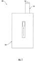
Figure 1 illustrates a front view of an aerosol delivery device including a housing having a cartridge therein, according to an example implementation of the present disclosure; -
Figure 2 schematically illustrates a sectional view through the aerosol delivery device ofFigure 1 , according to an example implementation of the present disclosure; -
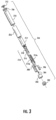
Figure 3 illustrates an exploded view of a cartridge suitable for use in the aerosol delivery device ofFigure 1 , according to an example implementation of the present disclosure; -
Figure 4 illustrates a perspective view of the aerosol delivery device ofFigure 1 , according to an example implementation of the present disclosure; -
Figure 5 illustrates an opposing perspective view of the aerosol delivery device ofFigure 1 , according to an example implementation of the present disclosure; and -
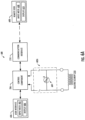
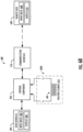
Figure 6A and6B illustrate various components of the aerosol delivery device ofFigure 1 including a resistance temperature detector (RTD), according to some example implementations. - The present disclosure will now be described more fully hereinafter with reference to example implementations thereof. These example implementations are described so that this disclosure will be thorough and complete, and will fully convey the scope of the disclosure to those skilled in the art. Indeed, the disclosure may be embodied in many different forms and should not be construed as limited to the implementations set forth herein; rather, these implementations are provided so that this disclosure will satisfy applicable legal requirements. As used in the specification and the appended claims, the singular forms "a," "an," "the" and the like include plural referents unless the context clearly dictates otherwise.
- As described hereinafter, example implementations of the present disclosure relate to aerosol delivery systems. Aerosol delivery systems according to the present disclosure use electrical energy to heat a material (preferably without combusting the material to any significant degree) to form an inhalable substance; and components of such systems have the form of articles most preferably are sufficiently compact to be considered hand-held devices. That is, use of components of preferred aerosol delivery systems does not result in the production of smoke in the sense that aerosol results principally from byproducts of combustion or pyrolysis of tobacco, but rather, use of those preferred systems results in the production of vapors resulting from volatilization or vaporization of certain components incorporated therein. In some example implementations, components of aerosol delivery systems may be characterized as electronic cigarettes, and those electronic cigarettes most preferably incorporate tobacco and/or components derived from tobacco, and hence deliver tobacco derived components in aerosol form.
- Aerosol generating pieces of certain preferred aerosol delivery systems may provide many of the sensations (e.g., inhalation and exhalation rituals, types of tastes or flavors, organoleptic effects, physical feel, use rituals, visual cues such as those provided by visible aerosol, and the like) of smoking a cigarette, cigar or pipe that is employed by lighting and burning tobacco (and hence inhaling tobacco smoke), without any substantial degree of combustion of any component thereof. For example, the user of an aerosol generating piece of the present disclosure can hold and use that piece much like a smoker employs a traditional type of smoking article, draw on one end of that piece for inhalation of aerosol produced by that piece, take or draw puffs at selected intervals of time, and the like.
- Aerosol delivery systems of the present disclosure also can be characterized as being vapor-producing articles or medicament delivery articles. Thus, such articles or devices can be adapted so as to provide one or more substances (e.g., flavors and/or pharmaceutical active ingredients) in an inhalable form or state. For example, inhalable substances can be substantially in the form of a vapor (i.e., a substance that is in the gas phase at a temperature lower than its critical point). Alternatively, inhalable substances can be in the form of an aerosol (i.e., a suspension of fine solid particles or liquid droplets in a gas). For purposes of simplicity, the term "aerosol" as used herein is meant to include vapors, gases and aerosols of a form or type suitable for human inhalation, whether or not visible, and whether or not of a form that might be considered to be smoke-like.
- Aerosol delivery systems of the present disclosure generally include a number of components provided within an outer body or shell, which may be referred to as a housing. The overall design of the outer body or shell can vary, and the format or configuration of the outer body that can define the overall size and shape of the aerosol delivery device can vary. Aerosol delivery devices are often configured in a manner that mimics aspects of certain traditional smoking devices such as cigarettes or cigars. In this regard, aerosol delivery devices typically define a substantially cylindrical configuration. Typically, an elongated body resembling the shape of a cigarette or cigar can be a formed from a single, unitary housing or the elongated housing can be formed of two or more separable bodies. For example, an aerosol delivery device can comprise an elongated shell or body that can be substantially tubular in shape and, as such, resemble the shape of a conventional cigarette or cigar. Aerosol delivery devices often include a control body and a cartridge which attach in an end-to-end relationship to define the substantially cylindrical configuration.
- While such configurations may provide a look and feel that is similar to traditional smoking articles, these configurations may suffer from certain detriments. For example, cylindrically-configured aerosol delivery devices may not define attachment points usable to retain the aerosol delivery device in a desired position when not in use. Further, the cylindrical configuration may result in the mouthpiece being exposed to the surrounding environment and therefore susceptible to contamination. Accordingly, it may be desirable to provide aerosol delivery devices in configurations that differ from shapes associated with traditional smoking articles.
- In one example, all of the components of the aerosol delivery device are contained within one housing. Alternatively, an aerosol delivery device can comprise two or more housings that are joined and are separable. For example, an aerosol delivery device can possess at one end a control body comprising a housing containing one or more reusable components (e.g., a rechargeable battery and various electronics for controlling the operation of that article), and at the other end and integral with or removably coupled thereto, an outer body or shell containing a disposable portion (e.g., a disposable flavor-containing cartridge).
- Aerosol delivery systems of the present disclosure most preferably comprise some combination of a power source (i.e., an electrical power source), at least one control component (e.g., means for actuating, controlling, regulating and ceasing power for heat generation, such as by controlling electrical current flow the power source to other components of the article - e.g., a microprocessor, individually or as part of a microcontroller), a heater or heat generation member (e.g., an electrical resistance heating element or other component), an aerosol precursor composition (e.g., commonly a liquid capable of yielding an aerosol upon application of sufficient heat, such as ingredients commonly referred to as "smoke juice," "e-liquid" and "e-juice"), and a mouthend region or tip for allowing draw upon the aerosol delivery device for aerosol inhalation (e.g., a defined airflow path through the article such that aerosol generated can be withdrawn therefrom upon draw). In some implementations, the electrical resisting heating element or other component, alone or in combination with one or more further elements, may be commonly referred to as an "atomizer," or may be or include a resistance temperature detector (RTD)
In various examples, an aerosol delivery device can comprise a reservoir configured to retain the aerosol precursor composition. The reservoir particularly can be formed of a porous material (e.g., a fibrous material) and thus may be referred to as a porous substrate (e.g., a fibrous substrate). - A fibrous substrate useful as a reservoir in an aerosol delivery device can be a woven or nonwoven material formed of a plurality of fibers or filaments and can be formed of one or both of natural fibers and synthetic fibers. For example, a fibrous substrate may comprise a fiberglass material. In particular examples, a cellulose acetate material can be used. In other example implementations, a carbon material can be used. In further implementations, viscose rayon or regenerated cellulose may be used. A reservoir may be substantially in the form of a container and may include a fibrous material included therein.
- In some implementations, the aerosol delivery device can include an indicator, which may comprise one or more light emitting diodes or a graphical user interface via a display. The indicator can be in communication with the control component through a connector circuit and illuminate, for example, during a user draw on the mouthend as detected by the flow sensor.
- More specific formats, configurations and arrangements of components within the aerosol delivery systems of the present disclosure will be evident in light of the further disclosure provided hereinafter. Additionally, the selection and arrangement of various aerosol delivery system components can be appreciated upon consideration of the commercially available electronic aerosol delivery devices, such as those representative products referenced in background art section of the present disclosure. Further, the arrangement of the components within the aerosol delivery device can also be appreciated upon consideration of the commercially available electronic aerosol delivery devices. Examples of commercially available products, for which the components thereof, methods of operation thereof, materials included therein, and/or other attributes thereof may be included in the devices of the present disclosure have been marketed as ACCORD® by Philip Morris Incorporated; ALPHA™, JOYE 510™ and M4™ by InnoVapor LLC; CIRRUS™ and FLING™ by White Cloud Cigarettes; BLU™ by Lorillard Technologies, Inc.; COHITA™, COLIBRF™, ELITE CLASSIC™, MAGNUM™, PHANTOM™ and SENSE™ by Epuffer® International Inc.; DUOPRO™, STORM™ and VAPORKING® by Electronic Cigarettes, Inc.; EGAR™ by Egar Australia; eGo-C™ and eGo-T™ by Joyetech; ELUSION™ by Elusion UK Ltd; EONSMOKE® by Eonsmoke LLC; FIN™ by FIN Branding Group, LLC; SMOKE® by Green Smoke Inc. USA; GREENARETTE™ by Greenarette LLC; HALLIGAN™, HENDU™, JET™, MAXXQ™, PINK™ and PITBULL™ by Smoke Stik®; HEATBAR™ by Philip Morris International, Inc.; HYDRO IMPERIAL™ and LXE™ from Crown7; LOGIC™ and THE CUBAN™ by LOGIC Technology; LUCI® by Luciano Smokes Inc.; METRO® by Nicotek, LLC; NJOY® and ONEJOY™ by Sottera, Inc.; NO. 7™ by SS Choice LLC; PREMIUM ELECTRONIC CIGARETTE™ by PremiumEstore LLC; RAPP E-MYSTICK™ by Ruyan America, Inc.; RED DRAGON™ by Red Dragon Products, LLC; RUYAN® by Ruyan Group (Holdings) Ltd.; SF® by Smoker Friendly International, LLC; GREEN SMART SMOKER® by The Smart Smoking Electronic Cigarette Company Ltd.; SMOKE ASSIST® by Coastline Products LLC; SMOKING EVERYWHERE® by Smoking Everywhere, Inc.; V2CIGS™ by VMR Products LLC; VAPOR NINE™ by VaporNine LLC; VAPOR4LIFE® by Vapor 4 Life, Inc.; VEPPO™ by E-CigaretteDirect, LLC; AVIGO, VUSE, VUSE CONNECT, VUSE FOB, VUSE HYBRID, ALTO, ALTO+, MODO, CIRO, FOX + FOG, AND SOLO+ by R. J. Reynolds Vapor Company; MISTIC MENTHOL by Mistic Ecigs; and VYPE by CN Creative Ltd. Yet other electrically powered aerosol delivery devices, and in particular those devices that have been characterized as so-called electronic cigarettes, have been marketed under the tradenames COOLER VISIONS™; DIRECT E-CIG™; DRAGONFLY™; EMIST™; EVERSMOKE™; GAMUCCI®; HYBRID FLAME™; KNIGHT STICKS™; ROYAL BLUES™; SMOKETIP®; SOUTH BEACH SMOKE™.
- Additional manufacturers, designers, and/or assignees of components and related technologies that may be employed in the aerosol delivery device of the present disclosure include Shenzhen Jieshibo Technology of Shenzhen, China; Shenzhen First Union Technology of Shenzhen City, China; Safe Cig of Los Angeles, CA; Janty Asia Company of the Philippines; Joyetech Changzhou Electronics of Shenzhen, China; SIS Resources; B2B International Holdings of Dover, DE; Evolv LLC of OH; Montrade of Bologna, Italy; Shenzhen Bauway Technology of Shenzhen, China; Global Vapor Trademarks Inc. of Pompano Beach, FL; Vapor Corp. of Fort Lauderdale, FL; Nemtra GMBH of Raschau-Markersbach, Germany, Perrigo L. Co. of Allegan, MI; Needs Co., Ltd.; Smokefree Innotec of Las Vegas, NV; McNeil AB of Helsingborg, Sweden; Chong Corp; Alexza Pharmaceuticals of Mountain View, CA; BLEC, LLC of Charlotte, NC; Gaitrend Sari of Rohrbach-lès-Bitche, France; FeelLife Bioscience International of Shenzhen, China; Vishay Electronic BMGH of Selb, Germany; Shenzhen Smaco Technology Ltd. of Shenzhen, China; Vapor Systems International of Boca Raton, FL; Exonoid Medical Devices of Israel; Shenzhen Nowotech Electronic of Shenzhen, China; Minilogic Device Corporation of Hong Kong, China; Shenzhen Kontle Electronics of Shenzhen, China, and Fuma International, LLC of Medina, OH, 21st Century Smoke of Beloit, WI, and Kimree Holdings (HK) Co. Limited of Hong Kong, China.
-
Figure 1 illustrates a front view of anaerosol delivery device 100, andFigure 2 illustrates a modified sectional view through the aerosol delivery device, according to an example implementation of the present disclosure. As illustrated, the aerosol delivery device may comprise a housing defining acontrol body 102 and acartridge 104. The cartridge may be moveable with respect to at least a portion of, or an entirety of, the housing. In particular, the cartridge may be moveable relative to at least a portion of the housing between an extended configuration illustrated inFigure 1 , and a retracted configuration illustrated inFigure 2 . Details with respect to the mechanisms and manners associated with movement of the cartridge relative to the housing are described hereinafter. - In some example implementations, either or both of the
control body 102 and thecartridge 104 of theaerosol delivery device 100 may be referred to as being disposable or as being reusable. The aerosol delivery device may include various other components disposed within the control body or the cartridge or otherwise coupled thereto. These components may be distributed between the control body and the cartridge in any of various manners. For example, the cartridge may include a replaceable battery or a rechargeable battery and thus may be combined with any type of recharging technology, including connection to a wall charger, connection to a car charger (i.e., a cigarette lighter receptacle), connection to a computer, such as through a universal serial bus (USB) cable or connector, connection to a photovoltaic cell (sometimes referred to as a solar cell) or a solar panel of solar cells. Further, in some example implementations, the cartridge may comprise a single-use cartridge, as disclosed inU.S. Pat. No. 8,910,639 to Chang et al. , which is incorporated herein by reference in its entirety. Accordingly, it should be understood that the described implementations are provided for example purposes only. - As illustrated in
Figure 1 , thecartridge 104 may include amouthpiece 106 that may be exposed when the cartridge is in the extended configuration. In other words, the mouthpiece may be positioned outside of thecontrol body housing 102 when the cartridge is in the extended configuration such that a user may engage the mouthpiece with his or her lips. Thus, the extended configuration of the cartridge is a configuration in which theaerosol delivery device 100 is configured to receive a draw on the mouthpiece such that the aerosol delivery device may produce and deliver an aerosol to a user in the manner described above. - In one example implementation, the
control body 102 andcartridge 104 forming theaerosol delivery device 100 may be permanently coupled to one another. Examples of aerosol delivery devices that may be configured to be disposable and/or which may include first and second outer bodies that are configured for permanent coupling are disclosed inU.S. Pat. App. Ser. No. 14/170,838 to Bless et al., filed February 3, 2014 - By way of example, in the illustrated implementation of
Figure 2 , theaerosol delivery device 100 includes apower source 202 positioned within thecontrol body 102. The power source may include, for example, a battery (single-use or rechargeable), solid-state battery, thin-film solid-state battery, supercapacitor or the like, or some combination thereof. Some examples of a suitable power source are provided inU.S. Pat. App. Ser. No. 14/918,926 to Sur et al., filed October 21, 2015 connector 204 may be moveably attached to the housing. Thecartridge 104 may be engaged with the connector so as to be moveable relative to at least a portion of the control body housing. In some implementations, the cartridge may be removably engaged with the connector and replaceable. - The
control body 102 of theaerosol delivery device 100 may additionally include acontrol component 206 received therein. As further shown inFigure 2 , in addition to themouthpiece 106, the cartridge may include abase 208,atomizer 210,reservoir 212, and anouter body 216, in which the cartridge is coupled to the control body at the base. The cartridge also may include one or more electronic components, which may include an integrated circuit, a memory component, a sensor, a resistor (e.g., resistance temperature detector (RTD), or the like. The electronic components may be adapted to communicate with thecontrol component 206 and/or with an external device by wired or wireless means. The electronic components may be positioned anywhere within the cartridge or thebase 208 thereof. - The
control component 206 of thecontrol body 102 may be configured to direct electrical power from thepower source 202 to thecartridge 104 to heat the aerosol precursor composition retained in thereservoir 212 with theatomizer 210 to produce a vapor, which may occur during a user draw on themouthpiece 106 of the cartridge. The control component includes a number of electronic components, and in some examples may be formed of a printed circuit board (PCB) that supports and electrically connects the electronic components. Examples of suitable electronic components include a microprocessor or processor core, an integrated circuit (IC), a memory, and the like. In some examples, the control component may include a microcontroller with an integrated processor core and memory, and which may further include one or more integrated input/output peripherals. - In some examples, the
control body 102 may include acommunication interface 218 that may be included on a PCB of thecontrol component 206, or a separate PCB that may be coupled to the PCB or one or more components of the control component. The communication interface may enable theaerosol delivery device 100 to wirelessly communicate with one or more networks, computing devices or other appropriately-enabled devices such as a suitable remote user interface. Examples of suitable computing devices include any of a number of different mobile computers. More particular examples of suitable mobile computers include portable computers (e.g., laptops, notebooks, tablet computers), mobile phones (e.g., cell phones, smartphones), wearable computers (e.g., smartwatches) and the like. In other examples, the computing device may be embodied as other than a mobile computer, such as in the manner of a desktop computer, server computer or the like. Examples of suitable manners according to which the aerosol delivery device may be configured to wirelessly communicate are disclosed inU.S. Pat. App. Ser. No. 14/327,776, filed July 10, 2014, to Ampolini et al. U.S. Pat. App. Ser. No. 14/609,032, filed January 29, 2016, to Henry, Jr. et al. - The
communication interface 218 may provide for transmitting and receiving data through, for example, a wired or wireless network such as a local area network (LAN), a metropolitan area network (MAN), and/or a wide area network (WAN), for example, the Internet. The communication interface may enable thecontrol component 206 to communicate with one or more further computing devices, either directly, or via the network. In this regard, the communication interface may include one or more interface mechanisms for enabling communication with other devices and/or networks. - The
communication interface 218 may include, for example, an antenna (or multiple antennas) and supporting hardware and/or software for enabling wireless communication with a communication network (e.g., a cellular network, Wi-Fi, WLAN, and/or the like), and/or for supporting device-to-device, short-range communication, in accordance with a desired communication technology. Examples of suitable short-range communication technologies that may be supported by the communication interface include various near field communication (NFC) technologies, wireless personal area network (WPAN) technologies and the like. More particular examples of suitable WPAN technologies include those specified by IEEE 802.15 standards or otherwise, including Bluetooth, Bluetooth low energy (Bluetooth LE), ZigBee, infrared (e.g., IrDA), radio-frequency identification (RFID), Wireless USB and the like. Yet other examples of suitable short-range communication technologies include Wi-Fi Direct, as well as certain other technologies based on or specified by IEEE 802.11 and/or IEEE 802.15.4 standards and that support direct device-to-device communication. - As noted above, the
cartridge 104 may be moveable relative to thecontrol body housing 102. In this regard, theaerosol delivery device 100 may further comprise anactuator 220. In particular, the actuator may be coupled to theconnector 204. Thereby, the actuator may be operatively engaged with the cartridge and configured to move the cartridge between the extended configuration and the retracted configuration. - As indicated above, in
Figure 1 , themouthpiece 106 may be exposed when thecartridge 104 is in the extended configuration. Conversely, as illustrated inFigure 2 , in the retracted configuration, the mouthpiece is relatively closer to thecontrol body housing 102 than in the extended configuration ofFigure 1 . In the retracted configuration, the mouthpiece may be flush with respect to the housing. In other words, an outer surface of the mouthpiece may substantially align with an outer surface of the housing. In another implementation the mouthpiece may be recessed with respect to the housing. In other words, a gap may be provided between the outer surface of the mouthpiece and the outer surface of the housing. -
Figure 3 illustrates a more particular example of thecartridge 104 ofFigures 1 and2 . As illustrated, in addition to themouthpiece 106,base 208,atomizer 210,reservoir 212, andouter body 216, the cartridge may also comprise abase shipping plug 302, acontrol component terminal 304, anelectronic control component 306, aflow tube 308, alabel 310, and amouthpiece shipping plug 312 according to an example implementation of the present disclosure. In various configurations, this structure may be referred to as a tank; and accordingly, the terms "cartridge," "tank" and the like may be used interchangeably to refer to a shell or other housing enclosing a reservoir for aerosol precursor composition, and including a heater. - The base 208 may be coupled to a first end of the
outer body 216, and themouthpiece 106 may be coupled to an opposing second end of the outer body, to at least partially enclose the remaining components of thecartridge 104 therein, with the exception of thelabel 310, themouthpiece shipping plug 312, and thebase shipping plug 302. The base may be configured to engage an associated device including thepower source 202. In some implementations, the base may comprise anti-rotation features that substantially prevent relative rotation between the cartridge and associated device including the power source. The base shipping plug may be configured to engage and protect the base prior to use of the cartridge. Similarly, the mouthpiece shipping plug may be configured to engage and protect the mouthpiece prior to use of the cartridge. - The
control component terminal 304, theelectronic control component 306, theflow tube 308, theatomizer 210, and thereservoir substrate 212 may be retained within theouter body 216. Thelabel 310 may at least partially surround the outer body and include information such as a product identifier thereon. Theatomizer 210 may comprise afirst heating terminal 314a and asecond heating terminal 314b, aliquid transport element 316 and aheating element 318 which may in some examples be or include a resistance temperature detector (RTD). - In some examples, a valve may be positioned between the reservoir and the heating element, and configured to control an amount of aerosol precursor composition passed or delivered from the reservoir to the heating element.
- The
reservoir 212 may be a container or can be a fibrous reservoir, as presently described. For example, the reservoir may comprise one or more layers of nonwoven fibers substantially formed into the shape of a tube encircling the interior of thecartridge 104. An aerosol precursor composition can be retained in the reservoir. Liquid components, for example, can be sorptively retained by the reservoir. The reservoir can be in fluid connection with theliquid transport element 316 adapted to wick or otherwise transport an aerosol precursor composition stored in the reservoir housing to theheating element 318. In particular, the liquid transport element can transport the aerosol precursor composition stored in the reservoir via capillary action to the heating element that is in the form of a metal wire coil in this example. As such, the heating element is in a heating arrangement with the liquid transport element. - In some examples, a microfluidic chip may be embedded in the
reservoir 212, and the aerosol precursor composition in the reservoir may be controlled by a micro pump, such as one based on microelectromechanical systems (MEMS) technology. Theheating element 318 may be configured to implement radio-frequency inductive based heating of the aerosol precursor composition without a wick or physical contact with the aerosol precursor composition, such as in a manner described inU.S. Pat. App. Ser. No. 14/934,763 to Davis et al., filed November 6, 2015 Figure 3 as described herein. In particular, specific combinations of heating members and transport elements as further described below may be incorporated into devices such as illustrated inFigure 3 as described herein. - Various examples of materials configured to produce heat when electrical current is applied therethrough may be employed to form the
heating element 318. The heating element in these examples may be resistive heating element such as a wire coil. Example materials from which the wire coil may be formed include Platinum (Pt) and Pt alloys, Titanium (Ti) and Ti alloys, Copper (Cu) and Cu alloys, Nickel (Ni) and Ni alloys, Kanthal (FeCrAl), Nichrome, Molybdenum disilicide (MoSi2), molybdenum silicide (MoSi), Molybdenum disilicide doped with Aluminum (Mo(Si,Al)2), graphite and graphite-based materials (e.g., carbon-based foams and yarns) and ceramics (e.g., positive or negative temperature coefficient ceramics). Example implementations of heating elements or heating members useful in aerosol delivery devices according to the present disclosure are further described below, and can be incorporated into devices such as illustrated inFigure 3 as described herein. - The
cartridge 104 may include a flow director defining a non-tubular configuration, an electronics compartment sealed with respect to a reservoir compartment, and/or any of the various other features and components disclosed therein. Accordingly, it should be understood that the particular implementation of the cartridge described herein is provided for example purposes only. In this regard, the cartridge is schematically illustrated inFigure 2 as including only themouthpiece 106, theouter body 216, theatomizer 210, thereservoir 212, and thebase 208, in light of the various alternate and additional components that may be included therein. - One or more components of the cartridge 108 may be configured to form an electrical connection with the
connector 204. For example, referring to the cartridge implementation ofFigure 3 , thefirst heating terminal 314a and thesecond heating terminal 314b (e.g., positive and negative terminals) at the opposing ends of theheating element 318 are configured to form an electrical connection with the connector. Further, the electronic control component 306 (seeFigure 3 ) may form an electrical connection with the connector through the control component terminal 304 (seeFigure 3 ). Components within the control body 102 (e.g., the control component 206) may thus employ the electronic control component to determine whether the cartridge is genuine and/or perform other functions. However, in other implementations the connection between the connector and the cartridge may not be electrical. In other words, the connection between the connector and the cartridge may be purely mechanical. In these implementations, atomization may occur outside of the cartridge or atomization may occur via other methods not requiring electrical connections between the cartridge and the housing such as via piezoelectric or radio frequency atomization. Alternatively, the power source may be positioned in the cartridge such that electrical connection with connector is not required. - In use, when a user draws on the
aerosol delivery device 100, theheating element 318 of theatomizer 210 is activated to vaporize components of the aerosol precursor composition. Drawing upon themouthpiece 106 of the aerosol delivery device causes ambient air to enter and pass through an opening in theconnector 204 or in thecartridge 104. In the cartridge, the drawn air combines with the formed vapor to form an aerosol. The aerosol is whisked, aspirated or otherwise drawn away from the heating element and out the opening in the mouthpiece of the aerosol delivery device. However, the flow of air may be received through other parts of the aerosol delivery device in other implementations. As noted above, in some implementations the cartridge may include theflow tube 308. The flow tube may be configured to direct the flow of air to the heating element. - In particular, a sensor in the
aerosol delivery device 100 may detect the flow of air throughout the aerosol delivery device. When a flow of air is detected, thecontrol component 206 may direct current to theheating element 318 through a circuit including thefirst heating terminal 314a and thesecond heating terminal 314b. Accordingly, the heating element may vaporize the aerosol precursor composition directed to an aerosolization zone from thereservoir 212 by theliquid transport element 316. Thus, themouthpiece 106 may allow passage of aerosol (i.e., the components of the aerosol precursor composition in an inhalable form) therethrough to a consumer drawing thereon. In some examples, in which the heating element is or includes a resistance temperature detector (RTD), the RTD may be used to provide an optimal temperature for specific e-liquids. For example, the aerosol precursor composition within acartridge 104 may have a particular flavor in which information indicating the flavor type is stored within memory of the cartridge (e.g., stored on a microchip). The information may be utilized to determine (or "read") the flavor of the aerosol precursor composition within the cartridge, and a value of the RTD may be adjusted to provide an optimal temperature for that specific flavor. -
Figure 4 illustrates a perspective view of theaerosol delivery device 100 in the closed configuration, andFigure 5 illustrates a perspective view of the aerosol delivery device in the extended configuration, having a particular form factor according to some example implementations. As illustrated, the housing of thecontrol body 102 may define an ergonomic shape configured to comfortably fit within a user's hand. The shape of the housing, however, is not limited and may be any shape that accommodates the various elements as described herein. In some implementations, the housing may be expressly non-cylindrical. - As illustrated in
Figure 4 , theaerosol delivery device 100 may additionally include aninput mechanism 402 configured to receive an input from a user. The input mechanism may take a variety of forms, such as a pushbutton, keypad, dial, touch screen, audio input interface, visual/image capture input interface, input in the form of sensor data, and the like. When the input mechanism is actuated, the aerosol delivery device may produce an output corresponding to a status of the aerosol delivery device. For example, the aerosol delivery device may output sound, vibration, or light. The aerosol delivery device may further comprise anindicator 404. The indicator may comprise a light transmitter (e.g., plastic or glass, which may be tinted a desired color). Further, the indicator may include a light emitter, which may comprise an incandescent bulb or light emitting diode (LED). Thereby, the light emitter may illuminate the light transmitter, which may direct the light outwardly therethrough to output a status of the aerosol delivery device. - The
indicator 404 may flash or otherwise illuminate to indicate a remaining or used portion of the capacity of thepower source 206 or thereservoir 212. For example, a relatively large number of flashes of the indicator upon actuation of theinput mechanism 402 may correspond to a relatively large remaining capacity of the power source or the reservoir. Conversely, a relatively small number of flashes of the indicator upon actuation of the input mechanism may correspond to a relatively small remaining capacity of the power source or the reservoir. However, the indicator and/or other output mechanisms may be employed to output various other information and/or output information in various other manners. Examples of other information that may be outputted include error messages, operational modes, historical usage information, etc. - In some implementations, the
aerosol delivery device 100 may include adisplay 406, as illustrated inFigures 4 and5 . The display may be provided in addition to, or as an alternate for, theindicator 404. The display may be configured to output various information including information regarding a status of the aerosol delivery device, information unrelated to the status of the aerosol delivery device (e.g., the present time), and/or non-informative graphics (e.g., graphics provided for user entertainment purposes). Thereby, the display may be configured to output any or all of the information described above (e.g., a remaining or used portion of the capacity of thepower source 206 or thereservoir 212, or a temperature of the heating element 318) in any form such as graphical form and/or a numerical form. - Further, in some implementations operation of the
display 406 may be controlled by theinput mechanism 402 or a separate input mechanism. The display, for example, may be a touchscreen and thus may be configured for user input. In some implementations, the display may provide icons, menus, or the like configured to allow a user to make control selections related to the functioning of the aerosol delivery device, check a specific status of the device, or the like. Although the display is illustrated as encompassing only a relatively small portion of the aerosol delivery device, it is understood that the display may cover a significantly greater portion of the aerosol delivery device. - The various components of an aerosol delivery device according to the present disclosure can be chosen from components described in the art and commercially available. Examples of batteries that can be used according to the disclosure are described in
U.S. Pat. App. Pub. No. 2010/0028766 to Peckerar et al. , which is incorporated herein by reference in its entirety. - The
aerosol delivery device 100 can incorporate the flow sensor or another sensor or detector for control of supply of electric power to theheating element 318 when aerosol generation is desired (e.g., upon draw during use). As such, for example, there is provided a manner or method of turning off the power supply to the heating element when the aerosol delivery device is not be drawn upon during use, and for turning on the power supply to actuate or trigger the generation of heat by the heating element during draw. Additional representative types of sensing or detection mechanisms, structure and configuration thereof, components thereof, and general methods of operation thereof, are described inU.S. Pat. No. 5,261,424 to Sprinkel, Jr. ,U.S. Pat. No. 5,372,148 to McCafferty et al. , andPCT Pat. App. Pub. No. WO 2010/003480 to Flick , all of which are incorporated herein by reference in their entireties. - The
aerosol delivery device 100 most preferably incorporates thecontrol component 206 or another control mechanism for controlling the amount of electric power to theheating element 318 during draw. Representative types of electronic components, structure and configuration thereof, features thereof, and general methods of operation thereof, are described inU.S. Pat. No. 4,735,217 to Gerth et al. ,U.S. Pat. No. 4,947,874 to Brooks et al. ,U.S. Pat. No. 5,372,148 to McCafferty et al. ,U.S. Pat. No. 6,040,560 to F'leischhauer et al. ,U.S. Pat. No. 7,040,314 to Nguyen et al .,U.S. Pat. No. 8,205,622 to Pan ,U.S. Pat. App. Pub. No. 2009/0230117 to Fernando et al. ,U.S. Pat. App. Pub. No. 2014/0060554 to Collet et al. ,U.S. Pat. App. Pub. No. 2014/0270727 to Ampolini et al. , andU.S. Pat. App. Ser. No. 14/209,191 to Henry et al., filed March 13, 2014 - Representative types of substrates, reservoirs or other components for supporting the aerosol precursor are described in
U.S. Pat. No. 8,528,569 to Newton ,U.S. Pat. App. Pub. No. 2014/0261487 to Chapman et al. ,U.S. Pat. App. Pub. No. 2015/0059780 to Davis et al., filed August 28, 2013 , andU.S. Pat. App. Ser. No. 14/170,838 to Bless et al., filed February 3, 2014 U.S. Pat. App. Pub. No. 2014/0209105 to Sears et al., which is incorporated herein by reference in its entirety. - The aerosol precursor composition, also referred to as a vapor precursor composition, may comprise a variety of components including, by way of example, a polyhydric alcohol (e.g., glycerin, propylene glycol or a mixture thereof), nicotine, tobacco, tobacco extract and/or flavorants. Representative types of aerosol precursor components and formulations also are set forth and characterized in
U.S. Pat. No. 7,217,320 to Robinson et al. andU.S. Pat. Pub. Nos. 2013/0008457 to Zheng et al. ;2013/0213417 to Chong et al. ;2014/0060554 to Collett et al. ;2015/0020823 to Lipowicz et al. ; and2015/0020830 to Koller , as well asWO 2014/182736 to Bowen et al , the disclosures of which are incorporated herein by reference. Other aerosol precursors that may be employed include the aerosol precursors that have been incorporated in the VUSE® product by R. J. Reynolds Vapor Company, the BLU™ product by Imperial Brands PLC, the MISTIC MENTHOL product by Mistic Ecigs, and the VYPE product by CN Creative Ltd. Also desirable are the so-called "smoke juices" for electronic cigarettes that have been available from Johnson Creek Enterprises LLC. - Additional representative types of components that yield visual cues or indicators may be employed in the
aerosol delivery device 100, such as LEDs and related components, auditory elements (e.g., speakers), vibratory elements (e.g., vibration motors) and the like. Examples of suitable LED components, and the configurations and uses thereof, are described inU.S. Pat. No. 5,154,192 to Sprinkel et al. ,U.S. Pat. No. 8,499,766 to Newton ,U.S. Pat. No. 8,539,959 to Scatterday , andU.S. Pat. App. Ser. No. 14/173,266 to Sears et al., filed February 5, 2014 - Yet other features, controls or components that can be incorporated into aerosol delivery devices of the present disclosure are described in
U.S. Pat. No. 5,967,148 to Harris et al. ,U.S. Pat. No. 5,934,289 to Watkins et al. ,U.S. Pat. No. 5,954,979 to Counts et al. ,U.S. Pat. No. 6,040,560 to F'leischhauer et al. ,U.S. Pat. No. 8,365,742 to Hon ,U.S. Pat. No. 8,402,976 to Fernando et al. ,U.S. Pat. App. Pub. No. 2005/0016550 to Katase ,U.S. Pat. App. Pub. No. 2010/0163063 to Fernando et al. ,U.S. Pat. App. Pub. No. 2013/0192623 to Tucker et al. ,U.S. Pat. App. Pub. No. 2013/0298905 to Leven et al. ,U.S. Pat. App. Pub. No. 2013/0180553 to Kim et al. ,U.S. Pat. App. Pub. No. 2014/0000638 to Sebastian et al. ,U.S. Pat. App. Pub. No. 2014/0261495 to Novak et al. ,U.S. Pat. App. Pub. No. 2014/0261408 to DePiano et al. , andU.S. Pat. App. Ser. No. 14/286,552 to Brinkley et al. , all of which are incorporated herein by reference in their entireties. - In accordance with some example implementations of the present disclosure, the temperature of the
aerosol delivery device 100, and more particularly theheating element 318, may be measured, displayed and/or controlled in real-time or near real-time (generally "real-time"). In these examples, accurate temperature feedback may be provided for a user. Further, the user may provide input through a wireless or on-board user interface for adjustment of the temperature. In these examples, the user may achieve a desired aerosol level based on the device temperature of the heating element without requiring explicit knowledge of the voltage, watts or ohms that are traditionally used as the basis for conveying such adjustments. -
Figures 6A and6B illustrate particular configurations of variouselectronic components 600 of theaerosol delivery device 100 that may be utilized for providing real-time display and/or control of the temperature of theheating element 318, according to some example implementations. For example, as shown, the aerosol delivery device may include acontrol component 206 operatively coupled to aRTD - In particular, the
RTD heating element 318. The RTD may also have a temperature coefficient of resistance that is invariable with respect to the temperature of the heating element. Based at least in part of these properties, thecontrol component 206 may be configured to measure the resistance of the RTD and therefrom determine the temperature of the heating element. The control component may then control a functional element of theaerosol delivery device 100 in real-time based on the determined temperature. It should be noted that although the example implementations herein are discussed with reference to thecontrol component 206 of thecontrol body 102, in some examples the functions of the control component may alternatively be executed by or in conjunction with thecontrol component 306 of thecartridge 104. - The
RTD RTD element 604 and lead wires Lw to couple the RTD element to a measuring instrument such as thecontrol component 206. It should be noted that although the illustrated implementations depict the RTD having two lead wires, the RTD may alternatively include various other multiple lead wire configurations such as three lead wire and four lead wire configurations. - More particularly,
Figures 6A and6B illustrate asuitable RTD Figure 6A , theRTD 602A may include anRTD element 604 such as a resistor R or sensing wire that may be operatively coupled to theheating element 318 for providing a measurable resistance that is variable and proportional to a temperature of the heating element. In some alternative examples, as shown inFigure 6B , theRTD 602B may be integrated with theheating element 318 of theaerosol delivery device 100. In these examples, in addition to being configured to produce heat to vaporize components of the aerosol precursor composition, the heating element itself may be utilized as the RTD element or sensing wire for providing a direct measurable resistance for determining the temperature thereof. - In integrated examples (
Figure 6B ), theheating element 318 utilized as theRTD element 604 may be formed of a metal that comprises a suitable intrinsic material property for providing a linear approximation of electrical resistance as a function of temperature. Examples of suitable metals include platinum (Pt), titanium (Ti), copper (Cu), nickel (Ni) or various alloys thereof. That is, the RTD element may be formed of a Pt, Ti, Cu or Ni alloy. The RTD element may also be formed of any other metal having a temperature coefficient of resistance (α) that is relatively large and does not substantially fluctuate as a function of temperature. The heating element may be utilized as the RTD element in implementations in which the heating element is formed from one of these suitable metals. - In some examples, the
RTD element 604 may also have a temperature coefficient of resistance that is suitably large enough to maintain a change in resistance of theRTD control component 206. As used herein, a "suitably large enough" temperature coefficient of resistance may refer to a temperature coefficient of resistance having a predetermined value relative to the processing power of the control component (e.g., a microprocessor). For example, a control component that includes at least a 12-bit microprocessor may be necessary to achieve the resolution required for effecting a change in resistance of the RTD per degree Celsius. In this example, the temperature coefficient of resistance may be greater than, or equal to, 0.001 which may be sufficient for an 8 to 12-bit processor. In some examples, the faster the processing speed of the control component, the lower the required value of temperature coefficient of resistance may be such that the processing speed of the control component and the temperature coefficient of resistance are inversely proportional to one another. For example, in one implementation, the RTD element may be formed of Nichrome, and a high-speed microprocessor may be used in conjunction with the RTD element even though Nichrome has a minuscule temperature coefficient of resistance (e.g., 0.00017). - For metals, electrical resistance increases as function of temperature in which an inverse correlation may be observed for intrinsic semiconductors and carbon. For certain metals or elements such as platinum (Pt), titanium (Ti), copper (Cu) and nickel (Ni), as well at least some of the alloys thereof, the temperature coefficient of resistance is relatively large and invariable with respect to the temperature of the heating element, and thus remains relativity constant as the temperature increases. This property allows for a linear approximation of electrical resistance as a function of temperature in which the following relation is shown in equation (1), where Ro is the resistance at temperature To (the initial temperature of the heating element 318), α is the temperature coefficient of resistance, and RT is the resistance at temperature T (the final temperature of the heating element):


- In any of these examples, the
RTD control body 102, or within thecartridge 104. In particular, in examples in which theRTD element 604 and theheating element 318 are separate and distinct components, the RTD may be located within the cartridge and operatively coupled to thecontrol component 206 when thecontrol body 102 and cartridge are engaged. Alternatively, the RTD may be located within the control body and operatively coupled to the heating element when the housing and cartridge are engaged. - Similarly, in instances in which the
RTD element 604 and theheating element 318 are integrated, theRTD cartridge 104 and operatively coupled to thecontrol component 206 when thecontrol body 102 and cartridge are engaged. Further, in some examples, components of the RTD may be located within both the control body and the cartridge. For example, the RTD element may be located within the cartridge and the lead wires Lw may be connected to the RTD element and further extend into the control body for coupling the RTD element with the control component. - In some examples, the
RTD power source 104 in order to maintain a set temperature throughout the power cycle. The PWM may be driven by control component 206 (e.g., a microcontroller) and one or more algorithms executed thereby and used to streamline the power utilized for each puff. In some examples, a voltage of thepower source 202 may steadily decline during a discharge thereof, and the power source may be configured to provide a duration of power for the usage of at least twocartridges 104. In this example, it is desirable for the voltage output, and thereby the temperature, for each puff from the first and second cartridge to remain constant the use of the cartridges. Thus the PWM may be configured such that the voltage output steadily increases for each increment of puffs. For example, in one implementation a first increment of puffs (e.g., 50 puffs) 70% voltage output, the next increment of puffs uses 75% voltage output, the next increment of puffs uses 80% voltage output, and so forth until the last increment of puffs uses 100% voltage output. In this example, as the voltage of the power source declines during discharge, the 100% voltage output nearing the end of the discharge would effect the same voltage as the 70% voltage out from the fully charged power source. - As indicated above, the
control component 206 may be configured to control a functional element of theaerosol delivery device 100 in real-time based on the determined temperature of theheating element 318. In these examples, control of the functional element may include output of the temperature for presentation by a display of a local or remote user interface, and/or adjustment of the power to the heating element. It should be noted that the control of the function element does not require an output of the temperature for presentation by the display in all instance. For example, in one implementation, the temperature may be hidden from, or otherwise not visible to, a user of theaerosol delivery device 100, and in this implementation the power may be adjusted to the heating element solely as a safety feature. Alternatively in some examples, the temperature may be visible to the user and the aerosol delivery device may include auser interface 606 that includes theinput mechanism 402 anddisplay 406 to enable user interaction with the aerosol delivery device. In some examples, the control component may be configured to receive a temperature-based setting from the user interface (e.g., via the input mechanism) and direct the power to the heating element in accordance with the temperature-based setting. - In addition to or in lieu of the
user interface 606, in some examples, the temperature of theaerosol delivery device 100 may also be displayable on, and/or controllable based on a temperature-based setting provided by aremote user interface 608 that may include asuitable input mechanism 608 anddisplay 610. In these examples, the aerosol delivery device may also include a communication interface 612 to enable communication with the remote user interface, and thereby enable presentation and control of the temperature by the remote user interface. For example, the aerosol delivery device may be configured to wirelessly communicate with the remote user interface, indirectly via one or more networks, according to some example implementations of the present disclosure. - In some implementations, the remote user interface 612 may be that of a remote computing device. Examples of suitable computing devices include any of a number of different mobile computers. More particular examples of suitable mobile computers include portable computers (e.g., laptops, notebooks, and tablet computers), mobile phones (e.g., cell phones, smartphones), wearable computers (e.g., smartwatches) and the like. In other examples, the computing device may be embodied as other than a mobile computer, such as in the manner of a desktop computer, server computer or the like.
- Examples of suitable manners according to which the aerosol delivery device may be configured to wirelessly communicate with a remote computing device including the remote user interface 612 are disclosed in
U.S. Pat. App. Ser. No. 14/327,776, filed July 10, 2014, to Ampolini et al. U.S. Pat. App. Ser. No. 14/609,032, filed January 29, 2016, to Henry, Jr. et al. - In these examples, control of the functional element of the
aerosol delivery device 100 may include output of the temperature for presentation by the remote display 612 in which thecommunication interface 608 may be coupled to thecontrol component 206 and configured to enable wireless communication of the temperature to the remote display. Similarly, the communication interface may be coupled to the control component and configured to enable wireless communication of the temperature-based setting from the remote user interface 608 (e.g., via remote input mechanism 610). - The foregoing description of use of the article(s) can be applied to the various example implementations described herein through minor modifications, which can be apparent to the person of skill in the art in light of the further disclosure provided herein. The above description of use, however, is not intended to limit the use of the article but is provided to comply with all necessary requirements of disclosure of the present disclosure. Any of the elements shown in the article(s) illustrated in
Figures 1 - 6A and6B or as otherwise described above may be included in an aerosol delivery device according to the present disclosure. - Many modifications and other implementations of the disclosure set forth herein will come to mind to one skilled in the art to which this disclosure pertains having the benefit of the teachings presented in the foregoing descriptions and the associated drawings. Therefore, it is to be understood that the disclosure is not to be limited to the specific implementations disclosed, and that modifications and other implementations are intended to be included within the scope of the appended claims. Moreover, although the foregoing descriptions and the associated drawings describe example implementations in the context of certain example combinations of elements and/or functions, it should be appreciated that different combinations of elements and/or functions may be provided by alternative implementations without departing from the scope of the appended claims. In this regard, for example, different combinations of elements and/or functions than those explicitly described above are also contemplated as may be set forth in some of the appended claims. Although specific terms are employed herein, they are used in a generic and descriptive sense only and not for purposes of limitation.
- 1. An aerosol delivery device comprising:
- at least one housing equipped with a heating element and containing an aerosol precursor composition, the heating element being controllable to activate and vaporize components of the aerosol precursor composition;
- a resistance temperature detector (RTD) having a resistance that is variable and proportional to a temperature of the heating element, the RTD also having a temperature coefficient of resistance that is invariable with respect to the temperature of the heating element; and
- a control component configured to direct power to the heating element to activate and vaporize components of the aerosol precursor composition, the control component being configured to measure the resistance of the RTD and therefrom determine the temperature of the heating element, and control at least one functional element in real time based on the temperature so determined, control of the at least one functional element including output of the temperature for presentation by a display, or adjustment of the power to the heating element.
- 2. The aerosol delivery device of Clause 1, wherein the RTD is integrated with the heating element and includes an RTD element configured to produce heat to vaporize components of the aerosol precursor composition.
- 3. The aerosol delivery device of Clause 1, wherein the RTD is formed of an element including platinum (Pt), titanium (Ti), copper (Cu) or nickel (Ni), or at least one alloy thereof.
- 4. The aerosol delivery device of Clause 1, wherein control of the at least one functional element includes output of the temperature for presentation by the display, and adjustment of the power to the heating element.
- 5. The aerosol delivery device of Clause 1, wherein control of the at least one functional element includes output of the temperature for presentation by the display, and
wherein the display is a remote display, and the aerosol delivery device further comprises a communication interface coupled to the control component and configured to enable wireless communication of the temperature to the remote display. - 6. The aerosol delivery device of Clause 1, wherein the control component is further configured to receive a temperature-based setting from a user interface, the control component being configured to direct the power to the heating element in accordance with the temperature-based setting.
- 7. The aerosol delivery device of Clause 6, wherein the user interface is a remote user interface, and the aerosol delivery device further comprises a communication interface coupled to the control component and configured to enable wireless communication of the temperature-based setting from the remote user interface.
- 8. A cartridge coupled or coupleable with a control body that is equipped with a control component, the control body being coupled or coupleable with the cartridge to form an aerosol delivery device, the cartridge comprising:
- a housing defining a reservoir configured to retain aerosol precursor composition;
- a heating element configured to operate in an active mode in which the cartridge is coupled with the control body, the heating element in the active mode being controllable by the control component to activate and vaporize components of the aerosol precursor composition; and
- a resistance temperature detector (RTD) having a resistance that is variable and proportional to a temperature of the heating element, the RTD also having a temperature coefficient of resistance that is invariable with respect to the temperature of the heating element,
- wherein the resistance of the RTD is measurable by the control component configured to measure the resistance of the RTD and therefrom determine the temperature of the heating element, and control at least one functional element in real time based on the temperature so determined, control of the at least one functional element including output of the temperature for presentation by a display, or adjustment of the power to the heating element.
- 9. The cartridge of Clause 8, wherein the RTD is integrated with the heating element and includes an RTD element configured to produce heat to vaporize components of the aerosol precursor composition.
- 10. The cartridge of Clause 8, wherein the RTD is formed of an element including platinum (Pt), titanium (Ti), copper (Cu) or nickel (Ni), or at least one alloy thereof.
- 11. The cartridge of Clause 8, wherein control of the at least one functional element includes output of the temperature for presentation by the display, and adjustment of the power to the heating element.
- 12. The cartridge of Clause 8, wherein control of the at least one functional element includes output of the temperature for presentation by the display, and
wherein the display is a remote display, and the aerosol delivery device further comprises a communication interface coupled to the control component and configured to enable wireless communication of the temperature to the remote display. - 13. The cartridge of Clause 8, wherein the control component is further configured to receive a temperature-based setting from a user interface, the control component being configured to direct the power to the heating element in accordance with the temperature-based setting.
- 14. The cartridge of Clause 13, wherein the user interface is a remote user interface, and the aerosol delivery device further comprises a communication interface coupled to the control component and configured to enable wireless communication of the temperature-based setting from the remote user interface.
- 15. A control body coupled or coupleable with a cartridge to form an aerosol delivery device, the cartridge being equipped with a heating element and a resistance temperature detector (RTD), and containing an aerosol precursor composition, the RTD having a resistance that is variable and proportional to a temperature of the heating element, the RTD also having a temperature coefficient of resistance that is invariable with respect to the temperature of the heating element, the control body comprising:
a control component configured to direct power to the heating element to activate and vaporize components of the aerosol precursor composition, the control component being configured to measure the resistance of the RTD and therefrom determine the temperature of the heating element, and control at least one functional element in real time based on the temperature so determined, control of the at least one functional element including output of the temperature for presentation by a display, or adjustment of the power to the heating element. - 16. The control body of Clause 15, wherein the RTD is integrated with the heating element and includes an RTD element configured to produce heat to vaporize components of the aerosol precursor composition.
- 17. The control body of Clause 15, wherein the RTD is formed of an element including platinum (Pt), titanium (Ti), copper (Cu) or nickel (Ni), or at least one alloy thereof.
- 18. The control body of Clause 15, wherein control of the at least one functional element includes output of the temperature for presentation by the display, and adjustment of the power to the heating element.
- 19. The control body of Clause 15, wherein control of the at least one functional element includes output of the temperature for presentation by the display, and
wherein the display is a remote display, and the aerosol delivery device further comprises a communication interface coupled to the control component and configured to enable wireless communication of the temperature to the remote display. - 20. The control body of Clause 15, wherein the control component is further configured to receive a temperature-based setting from a user interface, the control component being configured to direct the power to the heating element in accordance with the temperature-based setting.
- 21. The control body of Clause 20, wherein the user interface is a remote user interface, and the aerosol delivery device further comprises a communication interface coupled to the control component and configured to enable wireless communication of the temperature-based setting from the remote user interface.
- This divisional application is divided from parent application no.
EP17808595.7 EP3537904) filed at the EPO on 10 November 2017 , derived fromWO2017IB57059 WO2018087719 ). This divisional application comprises the full content of the earlier parent application as filed, including the description, claims, abstract, any drawings and any sequence listing. Nevertheless, protection may be sought for any features disclosed herein in combination with any features disclosed in the earlier parent application as filed, which is incorporated herein by reference.
Claims (10)
- An aerosol delivery device comprising:a cartridge (104) equipped with a heating element (318) and containing an aerosol precursor composition, the heating element (318) being controllable to activate and vaporize components of the aerosol precursor composition;a control body (102) equipped with a control component (206; 306), the control body (102) being coupled or coupleable with the cartridge (104) to form the aerosol delivery device;a resistance temperature detector, RTD, (602A; 602B; 604), wherein:the RTD (602A; 602B; 604) and the heating element (318) are separate and distinct;the RTD (602A; 602B; 604) is located within the cartridge (104) and operatively coupled to the control component (206; 306) when the control body (102) and the cartridge (104) are engaged;or the RTD (602A; 602B; 604) is located within the control body (102) and operatively coupled to the heating element (318) when the control body (102) and the cartridge (104) are engaged;the RTD (602A; 602B; 604) has a resistance that is variable and proportional to a temperature of the heating element (318);the RTD (602A; 602B; 604) also has a temperature coefficient of resistance that is invariable with respect to the temperature of the heating element (318); andthe control component (206; 306) is configured to direct power to the heating element (318) to activate and vaporize components of the aerosol precursor composition, and the control component (206; 306) is configured to measure the resistance of the RTD (602A; 602B; 604) and therefrom determine the temperature of the heating element (318), and control at least one functional element in real time based on the temperature so determined, the control of the at least one functional element including adjustment of the power to the heating element (318).
- A cartridge (104) coupleable with a control body (102) that is equipped with a control component (206; 306), the cartridge (104) comprising:a housing defining a reservoir configured to retain aerosol precursor composition;a heating element (318) configured to operate in an active mode in which the cartridge (104) is coupled with the control body (102), the heating element (318) in the active mode being controllable by the control component (206; 306) to activate and vaporize components of the aerosol precursor composition; anda resistance temperature detector, RTD, (602A; 602B; 604), wherein:the RTD (602A; 602B; 604) and the heating element (318) are separate and distinct;the RTD (602A; 602B; 604) is located within the cartridge (104) and operatively coupled to the control component (206; 306) when the control body (102) and the cartridge (104) are engaged;the RTD (602A; 602B; 604) has a resistance that is variable and proportional to a temperature of the heating element;the RTD (602A; 602B; 604) also has a temperature coefficient of resistance that is invariable with respect to the temperature of the heating element (318); andthe resistance of the RTD (602A; 602B; 604) is measurable by the control component (206; 306) for determining the temperature of the heating element (318), and for controlling at least one functional element in real time based on the temperature so determined, the control of the at least one functional element including adjustment of the power to the heating element (318).
- A control body (102) coupleable with a cartridge (104) equipped with a heating element (318) and containing an aerosol precursor composition, the control body (102) comprising a control component (206; 306) and a resistance temperature detector, RTD, (602A; 602B; 604), wherein:the RTD (602A; 602B; 604) and the heating element (318) are separate and distinct;the RTD (602A; 602B; 604) is located within the control body (102) and operatively coupled to the heating element (318) when the control body (102) and the cartridge (104) are engaged;the RTD (602A; 602B; 604) has a resistance that is variable and proportional to a temperature of the heating element (318);the RTD (602A; 602B; 604) also has a temperature coefficient of resistance that is invariable with respect to the temperature of the heating element (318); andthe control component (206; 306) is configured to direct power to the heating element (318) to activate and vaporize components of the aerosol precursor composition and the control component (206; 306) is configured to measure the resistance of the RTD (602A; 602B; 604) and therefrom determine the temperature of the heating element (318), and control at least one functional element in real time based on the temperature so determined, the control of the at least one functional element including adjustment of the power to the heating element (318).
- The aerosol delivery device, cartridge (104) or control body (102) of any preceding claim, wherein the RTD (602A; 602B; 604) is formed of an element including platinum (Pt), titanium (Ti), copper (Cu) or nickel (Ni), or at least one alloy thereof.
- The aerosol delivery device, cartridge (104) or control body (102) of any preceding claim, wherein the control of the at least one functional element includes output of the temperature for presentation by the display and adjustment of the power to the heating element (318).
- The aerosol delivery device or control body (102) of any preceding claim, wherein the control of the at least one functional element includes output of the temperature for presentation by a remote display and the aerosol delivery device or control body (102) further comprises a communication interface (218) coupled to the control component (206; 306) and configured to enable wireless communication of the temperature to the remote display.
- The aerosol delivery device or control body (102) of any preceding claim, wherein the control component (206; 306) is further configured to receive a temperature-based setting from a user interface (606), the control component (206; 306) being configured to direct the power to the heating element (318) in accordance with the temperature-based setting.
- The aerosol delivery device or control body (102) of claim 7, wherein the user interface (606) is a remote user interface (612), and the aerosol delivery device or control body (102) further comprises a communication interface (218) coupled to the control component (206; 306) and configured to enable wireless communication of the temperature-based setting from the remote user interface (612).
- The aerosol delivery device, cartridge (104) or control body (102) of any preceding claim, wherein the RTD (602A; 602B, 604) comprises an RTD element (604), wherein the RTD element (604) and the heating element (318) are separate and distinct.
- The aerosol delivery device, cartridge (104) or control body (102) of claim 9, wherein the RTD element (604) comprises a resistor or sensing wire.
Applications Claiming Priority (3)
| Application Number | Priority Date | Filing Date | Title |
|---|---|---|---|
| US15/349,619 US20180132526A1 (en) | 2016-11-11 | 2016-11-11 | Real-time temperature control for an aerosol delivery device |
| PCT/IB2017/057059 WO2018087719A1 (en) | 2016-11-11 | 2017-11-10 | Real-time temperature control for an aerosol delivery device |
| EP17808595.7A EP3537904A1 (en) | 2016-11-11 | 2017-11-10 | Real-time temperature control for an aerosol delivery device |
Related Parent Applications (1)
| Application Number | Title | Priority Date | Filing Date |
|---|---|---|---|
| EP17808595.7A Division EP3537904A1 (en) | 2016-11-11 | 2017-11-10 | Real-time temperature control for an aerosol delivery device |
Publications (2)
| Publication Number | Publication Date |
|---|---|
| EP4487721A2 true EP4487721A2 (en) | 2025-01-08 |
| EP4487721A3 EP4487721A3 (en) | 2025-03-19 |
Family
ID=60569974
Family Applications (2)
| Application Number | Title | Priority Date | Filing Date |
|---|---|---|---|
| EP17808595.7A Ceased EP3537904A1 (en) | 2016-11-11 | 2017-11-10 | Real-time temperature control for an aerosol delivery device |
| EP24212127.5A Pending EP4487721A3 (en) | 2016-11-11 | 2017-11-10 | Real-time temperature control for an aerosol delivery device |
Family Applications Before (1)
| Application Number | Title | Priority Date | Filing Date |
|---|---|---|---|
| EP17808595.7A Ceased EP3537904A1 (en) | 2016-11-11 | 2017-11-10 | Real-time temperature control for an aerosol delivery device |
Country Status (12)
| Country | Link |
|---|---|
| US (2) | US20180132526A1 (en) |
| EP (2) | EP3537904A1 (en) |
| JP (1) | JP7104464B2 (en) |
| KR (2) | KR102736740B1 (en) |
| CN (1) | CN109952037A (en) |
| BR (1) | BR112019008933A2 (en) |
| CA (1) | CA3042619A1 (en) |
| MY (1) | MY202010A (en) |
| PH (1) | PH12019501042A1 (en) |
| RU (1) | RU2019113434A (en) |
| UA (1) | UA128470C2 (en) |
| WO (1) | WO2018087719A1 (en) |
Families Citing this family (57)
| Publication number | Priority date | Publication date | Assignee | Title |
|---|---|---|---|---|
| KR101696363B1 (en) * | 2014-12-16 | 2017-01-13 | 신종수 | Electronic Cigarette |
| US10104913B2 (en) | 2015-04-22 | 2018-10-23 | Altria Client Services Llc | Pod assembly, dispensing body, and E-vapor apparatus including the same |
| US10687554B2 (en) | 2015-04-22 | 2020-06-23 | Altria Client Services Llc | Connection device, cartridge and electronic vaping device |
| US10064432B2 (en) | 2015-04-22 | 2018-09-04 | Altria Client Services Llc | Pod assembly, dispensing body, and E-vapor apparatus including the same |
| USD1052163S1 (en) | 2015-04-22 | 2024-11-19 | Altria Client Services Llc | Electronic vaping device |
| USD980507S1 (en) | 2015-04-22 | 2023-03-07 | Altria Client Services Llc | Electronic vaping device |
| USD874059S1 (en) | 2015-04-22 | 2020-01-28 | Altria Client Servies Llc | Electronic vaping device |
| US20180132526A1 (en) | 2016-11-11 | 2018-05-17 | Rai Strategic Holdings, Inc. | Real-time temperature control for an aerosol delivery device |
| US20180132529A1 (en) * | 2016-11-14 | 2018-05-17 | Rai Strategic Holdings, Inc. | Aerosol delivery device with integrated wireless connectivity for temperature monitoring |
| USD833672S1 (en) * | 2017-04-14 | 2018-11-13 | Changzhou Patent Electronic Technology Co., LTD | Electronic cigarette |
| USD854236S1 (en) * | 2017-04-22 | 2019-07-16 | Changzhou Patent Electronic Technology Co., LTD | Electronic cigarette |
| USD828953S1 (en) * | 2017-04-25 | 2018-09-18 | Shenzhen Smoore Technology Limited | Power supply device of electronic cigarettes |
| USD829982S1 (en) * | 2017-06-09 | 2018-10-02 | Shenzhen Smoore Technology Limited | Charging device for electronic cigarette |
| USD829983S1 (en) * | 2017-06-09 | 2018-10-02 | Shenzhen Smoore Technology Limited | Charging device for electronic cigarette |
| USD855250S1 (en) * | 2017-06-15 | 2019-07-30 | Joyetech Europe Holding Gmbh | Electronic cigarette |
| USD855249S1 (en) * | 2017-06-15 | 2019-07-30 | Joyetech Europe Holding Gmbh | Electronic cigarette |
| USD844232S1 (en) * | 2017-07-12 | 2019-03-26 | Changzhou Patent Electronic Technology Co., LTD | Electronic cigarette |
| USD883565S1 (en) * | 2017-10-28 | 2020-05-05 | Shenzhen Leruida Technology Co., Ltd | Smoking set |
| USD836242S1 (en) * | 2017-10-31 | 2018-12-18 | Avail Vapor Llc | Microvaporizer assembly |
| USD835839S1 (en) * | 2017-10-31 | 2018-12-11 | Avail Vapor Llc | Microvaporizer housing |
| USD850714S1 (en) * | 2017-11-02 | 2019-06-04 | Shenzhen Yukan Technology Co., Ltd. | Cigarette heater |
| USD828622S1 (en) * | 2017-11-14 | 2018-09-11 | Smiss Technology Co., Ltd. | Electronic vaporizer |
| EP3713627A4 (en) | 2017-11-22 | 2021-10-20 | Juul Labs, Inc. | USER INTERFACE AND USER EXPERIENCE FOR AN EVAPORATOR DEVICE |
| USD835840S1 (en) * | 2017-12-15 | 2018-12-11 | Huizhou Kimree Technology Co., Ltd. Shenzhen Branch | Electronic cigarette |
| USD829375S1 (en) * | 2017-12-18 | 2018-09-25 | Shenzhen Goldreams Technology Co., Ltd. | Electronic cigarette |
| EP4579498A3 (en) | 2017-12-21 | 2025-08-20 | Juul Labs, Inc. | Vaporizer controls |
| CN110547508B (en) * | 2018-05-31 | 2021-02-26 | 常州市派腾电子技术服务有限公司 | Electronic cigarette control method and device |
| EP3813913B1 (en) | 2018-06-26 | 2024-09-25 | Juul Labs, Inc. | Devices for cessation of nicotine addiction |
| KR102389828B1 (en) * | 2018-07-04 | 2022-04-22 | 주식회사 케이티앤지 | Aerosol generating device and method for controlling thereof |
| WO2020019122A1 (en) * | 2018-07-23 | 2020-01-30 | 湖北中烟工业有限责任公司 | Electric heating cigarette appliance having temperature and period adjustment functions |
| CN108990176A (en) * | 2018-08-15 | 2018-12-11 | 佛山市九龙机器有限公司 | Real time temperature shows gear controller |
| WO2020092245A1 (en) * | 2018-10-29 | 2020-05-07 | Zorday IP, LLC | Network-enabled electronic cigarette |
| JP6617189B1 (en) * | 2018-10-31 | 2019-12-11 | 日本たばこ産業株式会社 | Power supply unit for aerosol inhaler, aerosol inhaler, power control method for aerosol inhaler, and power control program for aerosol inhaler |
| US11592793B2 (en) | 2018-11-19 | 2023-02-28 | Rai Strategic Holdings, Inc. | Power control for an aerosol delivery device |
| CN109645571B (en) * | 2019-01-04 | 2023-10-13 | 深圳麦克韦尔科技有限公司 | Heating non-combustion device, heating assembly and calibration method thereof |
| GB201903245D0 (en) | 2019-03-11 | 2019-04-24 | Nicoventures Trading Ltd | Aerosol provision device |
| GB201903248D0 (en) | 2019-03-11 | 2019-04-24 | Nicoventures Trading Ltd | Aerosol provision device |
| TWI743739B (en) * | 2019-04-09 | 2021-10-21 | 美商瓦特洛威電子製造公司 | Thermal system with a temperature limiting device |
| KR102278590B1 (en) * | 2019-04-18 | 2021-07-16 | 주식회사 케이티앤지 | Aerosol Generating Device and Operation Method Thereof |
| WO2020243822A1 (en) | 2019-06-05 | 2020-12-10 | Canopy Growth Corporation | Convection and conduction vaporizer and method for operating the same |
| KR20210039199A (en) * | 2019-10-01 | 2021-04-09 | 주식회사 케이티앤지 | Aerosol generating device including display |
| CN110720670B (en) * | 2019-11-26 | 2023-12-12 | 上海龙殷生物科技有限公司 | Method, device and application for controlling atomized steam fragrance |
| CN111372330A (en) * | 2020-04-13 | 2020-07-03 | 深圳市康柏特科技开发有限公司 | Replaceable heating component, aerosol generating device and implementation method thereof |
| KR102427857B1 (en) | 2020-05-14 | 2022-08-01 | 주식회사 케이티앤지 | Aerosol generating system |
| EP4149303A1 (en) * | 2020-05-15 | 2023-03-22 | JT International SA | Aerosol generation device, aerosol generation system, control method |
| KR102455535B1 (en) * | 2020-06-16 | 2022-10-17 | 주식회사 케이티앤지 | Aerosol generating apparatus and method for operating the same |
| GB202012180D0 (en) * | 2020-08-05 | 2020-09-16 | Nicoventures Trading Ltd | Aerosol provision device |
| CN112306118B (en) * | 2020-10-21 | 2022-03-22 | 深圳市博迪科技开发有限公司 | Temperature control system and control method of aerosol generating device |
| KR102533745B1 (en) * | 2020-10-22 | 2023-05-17 | 주식회사 케이티앤지 | Aerosol generating device including real time clock and operation method of the same |
| CN112353009B (en) * | 2020-12-02 | 2024-12-27 | 深圳美众联科技有限公司 | Aerosol atomization device, atomization control method, control device and storage medium |
| US12520880B2 (en) | 2021-01-18 | 2026-01-13 | Altria Client Services Llc | Heat-not-burn (HNB) aerosol-generating devices including energy based heater control, and methods of controlling a heater |
| US20240188641A1 (en) | 2021-04-09 | 2024-06-13 | Nicoventures Trading Limited | Method of selecting a heater power setting in an aerosol provision system |
| EP4338608A4 (en) * | 2021-05-10 | 2025-08-20 | Japan Tobacco Inc | POWER SUPPLY UNIT FOR AEROSOL GENERATOR |
| JPWO2024105820A1 (en) * | 2022-11-16 | 2024-05-23 | ||
| CN118077962A (en) * | 2022-11-25 | 2024-05-28 | 深圳市合元科技有限公司 | Aerosol generating device and control method thereof |
| US20240277071A1 (en) * | 2023-02-21 | 2024-08-22 | Kt&G Corporation | Aerosol generating device and method of controlling the same |
| CN118923963A (en) * | 2023-05-09 | 2024-11-12 | 思摩尔国际控股有限公司 | Aerosol generating device and temperature control method thereof |
Citations (45)
| Publication number | Priority date | Publication date | Assignee | Title |
|---|---|---|---|---|
| US4735217A (en) | 1986-08-21 | 1988-04-05 | The Procter & Gamble Company | Dosing device to provide vaporized medicament to the lungs as a fine aerosol |
| US4947874A (en) | 1988-09-08 | 1990-08-14 | R. J. Reynolds Tobacco Company | Smoking articles utilizing electrical energy |
| US5154192A (en) | 1989-07-18 | 1992-10-13 | Philip Morris Incorporated | Thermal indicators for smoking articles and the method of application of the thermal indicators to the smoking article |
| US5261424A (en) | 1991-05-31 | 1993-11-16 | Philip Morris Incorporated | Control device for flavor-generating article |
| US5372148A (en) | 1993-02-24 | 1994-12-13 | Philip Morris Incorporated | Method and apparatus for controlling the supply of energy to a heating load in a smoking article |
| US5934289A (en) | 1996-10-22 | 1999-08-10 | Philip Morris Incorporated | Electronic smoking system |
| US5954979A (en) | 1997-10-16 | 1999-09-21 | Philip Morris Incorporated | Heater fixture of an electrical smoking system |
| US5967148A (en) | 1997-10-16 | 1999-10-19 | Philip Morris Incorporated | Lighter actuation system |
| US6040560A (en) | 1996-10-22 | 2000-03-21 | Philip Morris Incorporated | Power controller and method of operating an electrical smoking system |
| US20050016550A1 (en) | 2003-07-17 | 2005-01-27 | Makoto Katase | Electronic cigarette |
| US7040314B2 (en) | 2002-09-06 | 2006-05-09 | Philip Morris Usa Inc. | Aerosol generating devices and methods for generating aerosols suitable for forming propellant-free aerosols |
| US7217320B2 (en) | 2001-01-26 | 2007-05-15 | Memc Electronics Materials, Inc. | Low defect density silicon having a vacancy-dominated core substantially free of oxidation induced stacking faults |
| US20090230117A1 (en) | 2008-03-14 | 2009-09-17 | Philip Morris Usa Inc. | Electrically heated aerosol generating system and method |
| WO2010003480A1 (en) | 2008-07-08 | 2010-01-14 | Philip Morris Products S.A. | A flow sensor system |
| US20100028766A1 (en) | 2008-07-18 | 2010-02-04 | University Of Maryland | Thin flexible rechargeable electrochemical energy cell and method of fabrication |
| US7726320B2 (en) | 2006-10-18 | 2010-06-01 | R. J. Reynolds Tobacco Company | Tobacco-containing smoking article |
| US20100163063A1 (en) | 2008-12-24 | 2010-07-01 | Philip Morris Usa Inc. | Article Including Identification Information for Use in an Electrically Heated Smoking System |
| US8205622B2 (en) | 2009-03-24 | 2012-06-26 | Guocheng Pan | Electronic cigarette |
| US20130008457A1 (en) | 2011-07-04 | 2013-01-10 | Junxiang Zheng | Kind of preparation method of e-cigarette liquid |
| US8365742B2 (en) | 2006-05-16 | 2013-02-05 | Ruyan Investment (Holdings) Limited | Aerosol electronic cigarette |
| US8402976B2 (en) | 2008-04-17 | 2013-03-26 | Philip Morris Usa Inc. | Electrically heated smoking system |
| US20130180553A1 (en) | 2012-01-12 | 2013-07-18 | Meiko Maschinenbau Gmbh & Co. Kg | Dishwasher |
| US20130192623A1 (en) | 2012-01-31 | 2013-08-01 | Altria Client Services Inc. | Electronic cigarette |
| US8499766B1 (en) | 2010-09-15 | 2013-08-06 | Kyle D. Newton | Electronic cigarette with function illuminator |
| US20130213417A1 (en) | 2009-08-17 | 2013-08-22 | Chong Corporation | Tobacco Solution for Vaporized Inhalation |
| US8528569B1 (en) | 2011-06-28 | 2013-09-10 | Kyle D. Newton | Electronic cigarette with liquid reservoir |
| US8539959B1 (en) | 2012-03-23 | 2013-09-24 | Njoy, Inc. | Electronic cigarette configured to simulate the natural burn of a traditional cigarette |
| US20130298905A1 (en) | 2012-03-12 | 2013-11-14 | UpToke, LLC | Electronic vaporizing device and methods for use |
| US20140000638A1 (en) | 2012-06-28 | 2014-01-02 | R.J. Reynolds Tobacco Company | Reservoir and heater system for controllable delivery of multiple aerosolizable materials in an electronic smoking article |
| US20140060554A1 (en) | 2012-09-04 | 2014-03-06 | R.J. Reynolds Tobacco Company | Electronic smoking article comprising one or more microheaters |
| US20140096781A1 (en) | 2012-10-08 | 2014-04-10 | R. J. Reynolds Tobacco Company | Electronic smoking article and associated method |
| US20140209105A1 (en) | 2013-01-30 | 2014-07-31 | R.J. Reynolds Tobacco Company | Wick suitable for use in an electronic smoking article |
| US20140261495A1 (en) | 2013-03-15 | 2014-09-18 | R.J. Reynolds Tobacco Company | Cartridge and control body of an aerosol delivery device including anti-rotation mechanism and related method |
| US20140261487A1 (en) | 2013-03-14 | 2014-09-18 | R. J. Reynolds Tobacco Company | Electronic smoking article with improved storage and transport of aerosol precursor compositions |
| US20140270727A1 (en) | 2013-03-15 | 2014-09-18 | R. J. Reynolds Tobacco Company | Heating control arrangement for an electronic smoking article and associated system and method |
| US20140261408A1 (en) | 2013-03-15 | 2014-09-18 | R.J. Reynolds Tobacco Company | Cartridge for an aerosol delivery device and method for assembling a cartridge for a smoking article |
| US20140283859A1 (en) | 2010-05-15 | 2014-09-25 | Minusa Holdings Llc | Assembly directed airflow |
| WO2014182736A1 (en) | 2013-05-06 | 2014-11-13 | Ploom, Inc. | Nicotine salt formulations for aerosol devices and methods thereof |
| US8910639B2 (en) | 2012-09-05 | 2014-12-16 | R. J. Reynolds Tobacco Company | Single-use connector and cartridge for a smoking article and related method |
| US20150020823A1 (en) | 2013-07-19 | 2015-01-22 | Altria Client Services Inc. | Liquid aerosol formulation of an electronic smoking article |
| US20150020830A1 (en) | 2013-07-22 | 2015-01-22 | Altria Client Services Inc. | Electronic smoking article |
| US20150059780A1 (en) | 2013-08-28 | 2015-03-05 | R.J. Reynolds Tobacco Company | Carbon conductive substrate for electronic smoking article |
| US20150216232A1 (en) | 2014-02-03 | 2015-08-06 | R.J. Reynolds Tobacco Company | Aerosol Delivery Device Comprising Multiple Outer Bodies and Related Assembly Method |
| WO2017057059A1 (en) | 2015-09-30 | 2017-04-06 | ソニー株式会社 | Driving control device, driving control method, and program |
| WO2018087719A1 (en) | 2016-11-11 | 2018-05-17 | Rai Strategic Holdings, Inc. | Real-time temperature control for an aerosol delivery device |
Family Cites Families (18)
| Publication number | Priority date | Publication date | Assignee | Title |
|---|---|---|---|---|
| JP2949114B1 (en) * | 1998-08-04 | 1999-09-13 | 日本たばこ産業株式会社 | Electric flavor generation article heating control device |
| US9155848B2 (en) * | 2007-10-15 | 2015-10-13 | Vapir, Inc. | Method and system for vaporization of a substance |
| EP2253233A1 (en) * | 2009-05-21 | 2010-11-24 | Philip Morris Products S.A. | An electrically heated smoking system |
| US9999250B2 (en) * | 2010-05-15 | 2018-06-19 | Rai Strategic Holdings, Inc. | Vaporizer related systems, methods, and apparatus |
| JP5598991B2 (en) * | 2011-06-03 | 2014-10-01 | 日本たばこ産業株式会社 | Flavor generator |
| MY177353A (en) * | 2011-12-30 | 2020-09-14 | Philip Morris Products Sa | Aerosol-generating system with consumption monitoring and feedback |
| US9814262B2 (en) * | 2012-07-11 | 2017-11-14 | Sis Resources, Ltd. | Hot-wire control for an electronic cigarette |
| US9854841B2 (en) * | 2012-10-08 | 2018-01-02 | Rai Strategic Holdings, Inc. | Electronic smoking article and associated method |
| US20140190496A1 (en) * | 2012-11-28 | 2014-07-10 | E-Nicotine Technology, Inc. | Methods and devices for compound delivery |
| ES2670574T3 (en) * | 2013-05-20 | 2018-05-31 | Nu Mark Innovations Ltd | Development of applications for a network associated with an electronic cigarette |
| EA201691523A1 (en) * | 2014-01-27 | 2016-12-30 | Сис Рисорсез Лтд. | WIRE COMMUNICATION IN ELECTRONIC SMOKING DEVICE |
| US9602646B2 (en) * | 2014-01-29 | 2017-03-21 | Vaportronix Llc | Combination mobile phone case and electronic cigarette |
| US11825565B2 (en) * | 2014-06-14 | 2023-11-21 | Evolv, Llc | Electronic vaporizer having temperature sensing and limit |
| EA034186B1 (en) * | 2015-03-10 | 2020-01-15 | Джапан Тобакко Инк. | Method of manufacturing atomizing unit, non-combustion type flavor inhaler, atomizing unit and atomizing unit package |
| US10064432B2 (en) * | 2015-04-22 | 2018-09-04 | Altria Client Services Llc | Pod assembly, dispensing body, and E-vapor apparatus including the same |
| US20160325055A1 (en) * | 2015-05-08 | 2016-11-10 | Lunatech, Llc | Device To Deliver Cannabidiol And Associated Compounds To Promote Health |
| US10362803B2 (en) * | 2015-06-10 | 2019-07-30 | Evolv, Llc | Electronic vaporizer having reduced particle size |
| US11033054B2 (en) * | 2015-07-24 | 2021-06-15 | Rai Strategic Holdings, Inc. | Radio-frequency identification (RFID) authentication system for aerosol delivery devices |
-
2016
- 2016-11-11 US US15/349,619 patent/US20180132526A1/en not_active Abandoned
-
2017
- 2017-11-10 UA UAA201904645A patent/UA128470C2/en unknown
- 2017-11-10 RU RU2019113434A patent/RU2019113434A/en unknown
- 2017-11-10 EP EP17808595.7A patent/EP3537904A1/en not_active Ceased
- 2017-11-10 KR KR1020237027691A patent/KR102736740B1/en active Active
- 2017-11-10 WO PCT/IB2017/057059 patent/WO2018087719A1/en not_active Ceased
- 2017-11-10 KR KR1020197016563A patent/KR102568709B1/en active Active
- 2017-11-10 MY MYPI2019002437A patent/MY202010A/en unknown
- 2017-11-10 JP JP2019524347A patent/JP7104464B2/en active Active
- 2017-11-10 EP EP24212127.5A patent/EP4487721A3/en active Pending
- 2017-11-10 CA CA3042619A patent/CA3042619A1/en active Pending
- 2017-11-10 BR BR112019008933A patent/BR112019008933A2/en not_active Application Discontinuation
- 2017-11-10 CN CN201780070046.2A patent/CN109952037A/en active Pending
-
2019
- 2019-05-10 PH PH12019501042A patent/PH12019501042A1/en unknown
-
2024
- 2024-10-29 US US18/930,699 patent/US20250049137A1/en active Pending
Patent Citations (47)
| Publication number | Priority date | Publication date | Assignee | Title |
|---|---|---|---|---|
| US4735217A (en) | 1986-08-21 | 1988-04-05 | The Procter & Gamble Company | Dosing device to provide vaporized medicament to the lungs as a fine aerosol |
| US4947874A (en) | 1988-09-08 | 1990-08-14 | R. J. Reynolds Tobacco Company | Smoking articles utilizing electrical energy |
| US5154192A (en) | 1989-07-18 | 1992-10-13 | Philip Morris Incorporated | Thermal indicators for smoking articles and the method of application of the thermal indicators to the smoking article |
| US5261424A (en) | 1991-05-31 | 1993-11-16 | Philip Morris Incorporated | Control device for flavor-generating article |
| US5372148A (en) | 1993-02-24 | 1994-12-13 | Philip Morris Incorporated | Method and apparatus for controlling the supply of energy to a heating load in a smoking article |
| US6040560A (en) | 1996-10-22 | 2000-03-21 | Philip Morris Incorporated | Power controller and method of operating an electrical smoking system |
| US5934289A (en) | 1996-10-22 | 1999-08-10 | Philip Morris Incorporated | Electronic smoking system |
| US5954979A (en) | 1997-10-16 | 1999-09-21 | Philip Morris Incorporated | Heater fixture of an electrical smoking system |
| US5967148A (en) | 1997-10-16 | 1999-10-19 | Philip Morris Incorporated | Lighter actuation system |
| US7217320B2 (en) | 2001-01-26 | 2007-05-15 | Memc Electronics Materials, Inc. | Low defect density silicon having a vacancy-dominated core substantially free of oxidation induced stacking faults |
| US7040314B2 (en) | 2002-09-06 | 2006-05-09 | Philip Morris Usa Inc. | Aerosol generating devices and methods for generating aerosols suitable for forming propellant-free aerosols |
| US20050016550A1 (en) | 2003-07-17 | 2005-01-27 | Makoto Katase | Electronic cigarette |
| US8365742B2 (en) | 2006-05-16 | 2013-02-05 | Ruyan Investment (Holdings) Limited | Aerosol electronic cigarette |
| US7726320B2 (en) | 2006-10-18 | 2010-06-01 | R. J. Reynolds Tobacco Company | Tobacco-containing smoking article |
| US20090230117A1 (en) | 2008-03-14 | 2009-09-17 | Philip Morris Usa Inc. | Electrically heated aerosol generating system and method |
| US8402976B2 (en) | 2008-04-17 | 2013-03-26 | Philip Morris Usa Inc. | Electrically heated smoking system |
| WO2010003480A1 (en) | 2008-07-08 | 2010-01-14 | Philip Morris Products S.A. | A flow sensor system |
| US20100028766A1 (en) | 2008-07-18 | 2010-02-04 | University Of Maryland | Thin flexible rechargeable electrochemical energy cell and method of fabrication |
| US20100163063A1 (en) | 2008-12-24 | 2010-07-01 | Philip Morris Usa Inc. | Article Including Identification Information for Use in an Electrically Heated Smoking System |
| US8205622B2 (en) | 2009-03-24 | 2012-06-26 | Guocheng Pan | Electronic cigarette |
| US20130213417A1 (en) | 2009-08-17 | 2013-08-22 | Chong Corporation | Tobacco Solution for Vaporized Inhalation |
| US20140283859A1 (en) | 2010-05-15 | 2014-09-25 | Minusa Holdings Llc | Assembly directed airflow |
| US8499766B1 (en) | 2010-09-15 | 2013-08-06 | Kyle D. Newton | Electronic cigarette with function illuminator |
| US8528569B1 (en) | 2011-06-28 | 2013-09-10 | Kyle D. Newton | Electronic cigarette with liquid reservoir |
| US20130008457A1 (en) | 2011-07-04 | 2013-01-10 | Junxiang Zheng | Kind of preparation method of e-cigarette liquid |
| US20130180553A1 (en) | 2012-01-12 | 2013-07-18 | Meiko Maschinenbau Gmbh & Co. Kg | Dishwasher |
| US20130192623A1 (en) | 2012-01-31 | 2013-08-01 | Altria Client Services Inc. | Electronic cigarette |
| US20130298905A1 (en) | 2012-03-12 | 2013-11-14 | UpToke, LLC | Electronic vaporizing device and methods for use |
| US8539959B1 (en) | 2012-03-23 | 2013-09-24 | Njoy, Inc. | Electronic cigarette configured to simulate the natural burn of a traditional cigarette |
| US20140000638A1 (en) | 2012-06-28 | 2014-01-02 | R.J. Reynolds Tobacco Company | Reservoir and heater system for controllable delivery of multiple aerosolizable materials in an electronic smoking article |
| US20140060554A1 (en) | 2012-09-04 | 2014-03-06 | R.J. Reynolds Tobacco Company | Electronic smoking article comprising one or more microheaters |
| US8881737B2 (en) | 2012-09-04 | 2014-11-11 | R.J. Reynolds Tobacco Company | Electronic smoking article comprising one or more microheaters |
| US8910639B2 (en) | 2012-09-05 | 2014-12-16 | R. J. Reynolds Tobacco Company | Single-use connector and cartridge for a smoking article and related method |
| US20140096781A1 (en) | 2012-10-08 | 2014-04-10 | R. J. Reynolds Tobacco Company | Electronic smoking article and associated method |
| US20140209105A1 (en) | 2013-01-30 | 2014-07-31 | R.J. Reynolds Tobacco Company | Wick suitable for use in an electronic smoking article |
| US20140261487A1 (en) | 2013-03-14 | 2014-09-18 | R. J. Reynolds Tobacco Company | Electronic smoking article with improved storage and transport of aerosol precursor compositions |
| US20140261495A1 (en) | 2013-03-15 | 2014-09-18 | R.J. Reynolds Tobacco Company | Cartridge and control body of an aerosol delivery device including anti-rotation mechanism and related method |
| US20140261408A1 (en) | 2013-03-15 | 2014-09-18 | R.J. Reynolds Tobacco Company | Cartridge for an aerosol delivery device and method for assembling a cartridge for a smoking article |
| US20140270727A1 (en) | 2013-03-15 | 2014-09-18 | R. J. Reynolds Tobacco Company | Heating control arrangement for an electronic smoking article and associated system and method |
| WO2014182736A1 (en) | 2013-05-06 | 2014-11-13 | Ploom, Inc. | Nicotine salt formulations for aerosol devices and methods thereof |
| US20150020823A1 (en) | 2013-07-19 | 2015-01-22 | Altria Client Services Inc. | Liquid aerosol formulation of an electronic smoking article |
| US20150020830A1 (en) | 2013-07-22 | 2015-01-22 | Altria Client Services Inc. | Electronic smoking article |
| US20150059780A1 (en) | 2013-08-28 | 2015-03-05 | R.J. Reynolds Tobacco Company | Carbon conductive substrate for electronic smoking article |
| US20150216232A1 (en) | 2014-02-03 | 2015-08-06 | R.J. Reynolds Tobacco Company | Aerosol Delivery Device Comprising Multiple Outer Bodies and Related Assembly Method |
| WO2017057059A1 (en) | 2015-09-30 | 2017-04-06 | ソニー株式会社 | Driving control device, driving control method, and program |
| WO2018087719A1 (en) | 2016-11-11 | 2018-05-17 | Rai Strategic Holdings, Inc. | Real-time temperature control for an aerosol delivery device |
| EP3537904A1 (en) | 2016-11-11 | 2019-09-18 | RAI Strategic Holdings, Inc. | Real-time temperature control for an aerosol delivery device |
Non-Patent Citations (1)
| Title |
|---|
| R. J. REYNOLDS VAPOR COMPANY: "BLUTM product by Imperial Brands PLC", VYPE PRODUCT BY CN CREATIVE LTD. |
Also Published As
| Publication number | Publication date |
|---|---|
| UA128470C2 (en) | 2024-07-24 |
| MY202010A (en) | 2024-03-28 |
| KR20230124764A (en) | 2023-08-25 |
| JP2020500019A (en) | 2020-01-09 |
| KR20190078632A (en) | 2019-07-04 |
| RU2019113434A3 (en) | 2021-02-20 |
| WO2018087719A1 (en) | 2018-05-17 |
| CN109952037A (en) | 2019-06-28 |
| BR112019008933A2 (en) | 2019-07-16 |
| EP3537904A1 (en) | 2019-09-18 |
| EP4487721A3 (en) | 2025-03-19 |
| PH12019501042A1 (en) | 2019-08-19 |
| US20180132526A1 (en) | 2018-05-17 |
| RU2019113434A (en) | 2020-12-11 |
| KR102736740B1 (en) | 2024-11-29 |
| JP7104464B2 (en) | 2022-07-21 |
| CA3042619A1 (en) | 2018-05-17 |
| US20250049137A1 (en) | 2025-02-13 |
| KR102568709B1 (en) | 2023-08-21 |
Similar Documents
| Publication | Publication Date | Title |
|---|---|---|
| US20250049137A1 (en) | Real-time temperature control for an aerosol delivery device | |
| US11844152B2 (en) | Detachable power source for an aerosol delivery device | |
| US11812790B2 (en) | User interface for an aerosol delivery device | |
| EP4278916A2 (en) | Camera for an aerosol delivery device | |
| US11606971B2 (en) | Video analytics camera system for an aerosol delivery device | |
| EP4706430A2 (en) | Micropump for an aerosol delivery device | |
| EP4643914A2 (en) | Analog control component for an aerosol delivery device |
Legal Events
| Date | Code | Title | Description |
|---|---|---|---|
| PUAI | Public reference made under article 153(3) epc to a published international application that has entered the european phase |
Free format text: ORIGINAL CODE: 0009012 |
|
| STAA | Information on the status of an ep patent application or granted ep patent |
Free format text: STATUS: THE APPLICATION HAS BEEN PUBLISHED |
|
| AC | Divisional application: reference to earlier application |
Ref document number: 3537904 Country of ref document: EP Kind code of ref document: P |
|
| AK | Designated contracting states |
Kind code of ref document: A2 Designated state(s): AL AT BE BG CH CY CZ DE DK EE ES FI FR GB GR HR HU IE IS IT LI LT LU LV MC MK MT NL NO PL PT RO RS SE SI SK SM TR |
|
| REG | Reference to a national code |
Ref country code: DE Ref legal event code: R079 Free format text: PREVIOUS MAIN CLASS: A24F0047000000 Ipc: A24F0040510000 |
|
| PUAL | Search report despatched |
Free format text: ORIGINAL CODE: 0009013 |
|
| AK | Designated contracting states |
Kind code of ref document: A3 Designated state(s): AL AT BE BG CH CY CZ DE DK EE ES FI FR GB GR HR HU IE IS IT LI LT LU LV MC MK MT NL NO PL PT RO RS SE SI SK SM TR |
|
| RIC1 | Information provided on ipc code assigned before grant |
Ipc: A24F 40/10 20200101ALN20250213BHEP Ipc: A24F 40/65 20200101ALI20250213BHEP Ipc: A24F 40/60 20200101ALI20250213BHEP Ipc: A24F 40/42 20200101ALI20250213BHEP Ipc: A24F 40/50 20200101ALI20250213BHEP Ipc: A24F 40/51 20200101AFI20250213BHEP |
|
| P01 | Opt-out of the competence of the unified patent court (upc) registered |
Free format text: CASE NUMBER: APP_31942/2025 Effective date: 20250702 |
|
| STAA | Information on the status of an ep patent application or granted ep patent |
Free format text: STATUS: REQUEST FOR EXAMINATION WAS MADE |
|
| 17P | Request for examination filed |
Effective date: 20250918 |