EP4487720A1 - Aerosol generation device and aerosol generation system - Google Patents
Aerosol generation device and aerosol generation system Download PDFInfo
- Publication number
- EP4487720A1 EP4487720A1 EP22929634.8A EP22929634A EP4487720A1 EP 4487720 A1 EP4487720 A1 EP 4487720A1 EP 22929634 A EP22929634 A EP 22929634A EP 4487720 A1 EP4487720 A1 EP 4487720A1
- Authority
- EP
- European Patent Office
- Prior art keywords
- aerosol
- generation
- rotating element
- accommodating cavity
- generation device
- Prior art date
- Legal status (The legal status is an assumption and is not a legal conclusion. Google has not performed a legal analysis and makes no representation as to the accuracy of the status listed.)
- Pending
Links
Images


Classifications
-
- A—HUMAN NECESSITIES
- A24—TOBACCO; CIGARS; CIGARETTES; SIMULATED SMOKING DEVICES; SMOKERS' REQUISITES
- A24F—SMOKERS' REQUISITES; MATCH BOXES; SIMULATED SMOKING DEVICES
- A24F40/00—Electrically operated smoking devices; Component parts thereof; Manufacture thereof; Maintenance or testing thereof; Charging means specially adapted therefor
- A24F40/40—Constructional details, e.g. connection of cartridges and battery parts
-
- A—HUMAN NECESSITIES
- A24—TOBACCO; CIGARS; CIGARETTES; SIMULATED SMOKING DEVICES; SMOKERS' REQUISITES
- A24F—SMOKERS' REQUISITES; MATCH BOXES; SIMULATED SMOKING DEVICES
- A24F40/00—Electrically operated smoking devices; Component parts thereof; Manufacture thereof; Maintenance or testing thereof; Charging means specially adapted therefor
- A24F40/10—Devices using liquid inhalable precursors
-
- A—HUMAN NECESSITIES
- A24—TOBACCO; CIGARS; CIGARETTES; SIMULATED SMOKING DEVICES; SMOKERS' REQUISITES
- A24F—SMOKERS' REQUISITES; MATCH BOXES; SIMULATED SMOKING DEVICES
- A24F40/00—Electrically operated smoking devices; Component parts thereof; Manufacture thereof; Maintenance or testing thereof; Charging means specially adapted therefor
- A24F40/20—Devices using solid inhalable precursors
-
- A—HUMAN NECESSITIES
- A24—TOBACCO; CIGARS; CIGARETTES; SIMULATED SMOKING DEVICES; SMOKERS' REQUISITES
- A24F—SMOKERS' REQUISITES; MATCH BOXES; SIMULATED SMOKING DEVICES
- A24F40/00—Electrically operated smoking devices; Component parts thereof; Manufacture thereof; Maintenance or testing thereof; Charging means specially adapted therefor
- A24F40/40—Constructional details, e.g. connection of cartridges and battery parts
- A24F40/42—Cartridges or containers for inhalable precursors
-
- A—HUMAN NECESSITIES
- A24—TOBACCO; CIGARS; CIGARETTES; SIMULATED SMOKING DEVICES; SMOKERS' REQUISITES
- A24F—SMOKERS' REQUISITES; MATCH BOXES; SIMULATED SMOKING DEVICES
- A24F40/00—Electrically operated smoking devices; Component parts thereof; Manufacture thereof; Maintenance or testing thereof; Charging means specially adapted therefor
- A24F40/40—Constructional details, e.g. connection of cartridges and battery parts
- A24F40/46—Shape or structure of electric heating means
-
- A—HUMAN NECESSITIES
- A24—TOBACCO; CIGARS; CIGARETTES; SIMULATED SMOKING DEVICES; SMOKERS' REQUISITES
- A24F—SMOKERS' REQUISITES; MATCH BOXES; SIMULATED SMOKING DEVICES
- A24F40/00—Electrically operated smoking devices; Component parts thereof; Manufacture thereof; Maintenance or testing thereof; Charging means specially adapted therefor
- A24F40/70—Manufacture
-
- A—HUMAN NECESSITIES
- A24—TOBACCO; CIGARS; CIGARETTES; SIMULATED SMOKING DEVICES; SMOKERS' REQUISITES
- A24F—SMOKERS' REQUISITES; MATCH BOXES; SIMULATED SMOKING DEVICES
- A24F40/00—Electrically operated smoking devices; Component parts thereof; Manufacture thereof; Maintenance or testing thereof; Charging means specially adapted therefor
- A24F40/85—Maintenance, e.g. cleaning
Definitions
- the present disclosure relates to the field of electronic atomization technologies, in particular to an aerosol-generation device and an aerosol-generation system.
- the aerosol-generation device is an appliance for heating and atomizing an aerosol-generation article to form aerosols.
- heating technologies for the aerosol-generation article mainly include the following schemes: (1) resistance heating in a direct-contact way, (2) induction electromagnetic heating, (3) microwave heating, and so on.
- the scheme (1) and scheme (2) are both heat-conduction methods, require long waiting time for warm up when using, and may have the problem of non-uniform heating, and the suction experience of the user may be affected.
- the scheme (3) is radiation heating, the heating occurs simultaneously throughout the entire interior of the aerosol-generation article, and the heating is rapid and uniform.
- the aerosol-generation article is usually filled in the heating cavity as a whole.
- each rapid heating of the aerosol-generation device may heat the aerosol-generation article as a whole to a temperature of about 300-400 °C, resulting in a large change in the taste of the aerosol-generation article in multiple times of suction.
- An aerosol-generation device and an aerosol-generation system are provided in some embodiments of the present disclosure, a uniform heating may be achieved, and the taste of aerosols may be kept fresh and consistent.
- the aerosol-generation device includes an accommodating cavity body, a heating assembly, and a delivering assembly.
- the accommodating cavity body defines an accommodating cavity.
- the accommodating cavity is configured to accommodate at least one aerosol-generation article.
- the delivering assembly configured to deliver an aerosol-generation article of the at least one aerosol-generation article to an atomization region.
- the heating assembly is configured to heat the aerosol-generation article on the atomization region to generate aerosols.
- the aerosol-generation system includes the aforesaid aerosol-generation device and at least one aerosol-generation article accommodated in the aerosol-generation device.
- the storing position of the at least one aerosol-generation article is different from the atomization region
- the at least one aerosol-generation article is delivered to the atomization region in batches through the delivering assembly
- the laser assembly may only heat the aerosol-generation article delivered to the atomization region every time.
- the at least one aerosol-generation article may be heated uniformly and quickly, and the atomization utilization rate may be high.
- the aerosol-generation article to be atomized may be delivered to the atomization region for continuous atomization, in this way, the preset number of aerosol-generation articles delivered to the atomization region for atomization may be selected according to the quantity of aerosols corresponding to each suction or several times of suction, so that the taste of aerosols sucked by users may be kept fresh and kept consistent in an early stage and a late stage.
- aerosol-generation article S aerosol-generation article S'; shell 11; main body 111; cover 112; accommodating cavity body 12; accommodating cavity 121; rotating element 13; atomization hole 131; receiving groove 132; heating assembly 14; suction nozzle 15; air-outlet channel 151; first driving element 16; recycling cavity body 17; recycling cavity 171; bearing plate 18; first opening 181; second opening 182; atomization region 183; sealing cover 19; second driving element 20; adapter 21; airflow channel 211; pressing element 22.
- first”, “second”, and “third” in the embodiments of the present disclosure are only used for descriptive purposes, and cannot be understood as indicating or implying relative importance or implicitly indicating the number of indicated technical features. Thus, the features defined with “first”, “second”, and “third” may explicitly or implicitly include at least one of the features.
- "a plurality of” means at least two, e.g., two, three, etc., unless specifically defined otherwise.
- All directional indications (such as up, down, left, right, front, back) in the embodiments of the present disclosure are only configured to account for relative positional relationships, motion conditions, etc., between components in a particular orientation (as shown in the drawings), if the particular orientation changed, correspondingly changes the directional indications.
- the terms "including” and “having” and any variations thereof are intended to cover non-exclusive inclusions. For example, a process, method, system, product, or device that includes a series of steps or units is not limited to the listed steps or units, but optionally includes unlisted steps or units, or optionally also includes other steps or units inherent to these processes, methods, products or equipment.
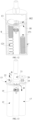
- FIG. 1 is a schematic overall structural view of an aerosol-generation system according to some embodiments of the present disclosure.
- FIG. 2 is a schematic exploded view of FIG. 1 according to some embodiments of the present disclosure.
- FIG. 3 is a perspective view of an aerosol-generation system other than a shell according to some embodiments of the present disclosure.
- an aerosol-generation system is provided.
- the aerosol-generation system includes an aerosol-generation device and at least one aerosol-generation article S accommodated in the aerosol-generation device.
- the aerosol-generation device is configured to heat the at least one aerosol-generation article S by laser, so as to form aerosols for a user to suck.
- the at least one aerosol-generation article S may be a solid substrate, which may include plant leaves such as vanilla leaves, tea leaves, and mint leaves, and may include one or more kinds of powders, particles, fragments, thin strips, strips, and sheets.
- the solid substrate may include additional volatile aroma compounds, and the volatile aroma compounds may be released when the substrate is heated.
- the at least one aerosol-generation article S may also be a liquid substrate, such as oils and medicinal liquids with aroma components added. In the following embodiments, the at least one aerosol-generation article S may be illustrated as the solid substrate for example.
- the at least one aerosol-generation article S includes a plurality of aerosol-generation articles S.
- Each of the plurality of aerosol-generation articles S is in the shape of a sheet, and the plurality of aerosol-generation articles S are stacked with each other.
- the density of the aerosol-generation articles S may be increased, the accommodating quantity of the aerosol-generation articles S in a fixed volume may be increased, and the storage quantity of aerosol-generation articles S in the aerosol-generation device may be increased.
- a long duration of suction of the aerosol-generation device may be achieved after a single filling.
- the thickness of each aerosol-generation article S is 0.2-2mm.
- each aerosol-generation article S is 0.5-1mm. In some embodiments, 30 or more aerosol-generation articles S may be accommodated in the aerosol-generation device. Each aerosol-generation article S may be heated for one to five times to support a single suction, so as to ensure the consistency of the aerosols generated by atomization. In this way, after a single filling, the aerosol-generation device may be sucked by more than 30 times, or even more than 100 times, and the taste of the aerosols is long-term effective and consistent.
- each aerosol-generation article S may be 2-15mm.
- the surface of each aerosol-generation article S may be provided with a through hole, and the diameter the through hole and the filling ratio of each aerosol-generation article S may be designed according to different airflow-resistance requirements, so to ensure the release of aerosols.
- the specific structure and function of the aerosol-generation device may be seen in any one of the following embodiments.
- the aerosol-generation device includes a shell 11, an accommodating cavity body 12 arranged in the shell 11, a delivering assembly arranged in the shell 11, a heating assembly 14 arranged in the shell 11, and a suction nozzle 15.
- the shell 11 may include a main body 111 and a cover 112.
- the cover 112 is covered on the main body 111.
- the main body 111 and the cover 112 cooperatively form a hollow body and are configured as the outer surface of the aerosol-generation device, which is configured to protect assemblies in the hollow body.
- the shell 11 may also be assembled by engaging a left portion and a right portion together or engaging a front portion and a rear portion together, and the present disclosure does not limit the structure of the shell 11.
- the accommodating cavity body 12, the delivering assembly, and the heating assembly 14 are housed in the hollow body.
- the suction nozzle 15 is arranged on the shell 11 and defines an air-outlet channel 151.
- the air-outlet channel 151 is configured to be in communication with external atmosphere.
- the suction nozzle 15 may also be directly defined by the shell 11.
- the suction nozzle 15 is a cylindrical tube inserted in a through hole on the top wall of the main body 111.
- the accommodating cavity body 12 defines an accommodating cavity 121.
- the accommodating cavity 121 is configured to accommodate the plurality of aerosol-generation articles S. That is, the plurality of aerosol-generation articles S in the aerosol-generation system are stacked with each other along a depth direction of the accommodating cavity 121.
- the accommodating cavity body 12 is a structure independent from the shell 11, and is detachably connected to the shell 11, in this way, the accommodating cavity body 12 is disposable. After the accommodated aerosol-generation articles S are completely heated, it is convenient to take out the accommodating cavity body 12, and new aerosol-generation articles S may be filled rapidly. In some embodiments, another new accommodating cavity body 12 with aerosol-generation articles S may be replaced, so as to improve the replaceability of the accommodating cavity body 12.
- the accommodating cavity 121 may be cylindrical.
- the peripheral shape of the accommodating cavity 121 may match the peripheral shape of each aerosol-generation article S, and the diameter of the accommodating cavity 121 may be equal to or slightly greater than the diameter of each aerosol-generation article S, so as to prevent the aerosol-generation articles S from shaking in the accommodating cavity 121, and it is easy for the aerosol-generation article S to be filled in the accommodating cavity 121 or to be moved out of the accommodating cavity 121.
- the material of the accommodating cavity body 12 may be harmless metal materials, such as aluminum alloy of series 6, stainless steel, etc., or harmless plastic materials, such as polyetheretherketone (PEEK), etc.
- the delivering assembly is configured to deliver the aerosol-generation articles S to an atomization region 183 in batches.
- the delivering assembly is configured to deliver the plurality of aerosol-generation articles S to the atomization region 183 in sequence. That is, the delivering assembly delivers a preset number of aerosol-generation articles S to the atomization region 183 every time, rather than delivers all the aerosol-generation articles S in the accommodating cavity 121 to the atomization region 183 at one time.
- the at least one aerosol-generation article S when the at least one aerosol-generation article S is a liquid substrate, it may be controlled that a part of the aerosol-generation article S flows from the accommodating cavity 121 to the delivering assembly every time, or the delivering assembly may take a part of the aerosol-generation article S out of the accommodating cavity 121 and deliver the part of the aerosol-generation article S to the atomization region 183, so as to deliver the aerosol-generation article S in the accommodating cavity 121 to the atomization region 183 by several times.
- the delivering assembly may include a rotating element 13, a power element (which is not shown in drawings), and a control circuit (which is not shown in drawings).
- the rotating element 13 is connected to the power element.
- the power element is configured to drive the rotating element 13 to rotate, so as to deliver the aerosol-generation article S to the atomization region 183 through the rotation of the rotating element 13.
- the rotating element 13 may be a rotatable plate, a movable machine arm, a movable machine hand, etc.
- the power element may be a motor, a pump, etc.
- the rotating element 13 may also be driven by a manual mechanical mechanism.
- a part of the rotating element 13 may be extended out of the shell 11 and may be rotated manually, in this way, the usage of the power element may be reduced, and the volume of the aerosol-generation device may be reduced.
- the control circuit is electrically connected to the power element and the heating assembly 14 respectively.
- the control circuit is configured to control the power element to enable the rotating element 13 to move the aerosol-generation article S to the atomization region 183, and control the heating assembly 14 to heat the aerosol-generation article S on the atomization region 183 after the rotating element 13 delivers the aerosol-generation article S to the atomization region 183.
- the control circuit may be powered by a built-in battery assembly.
- the control circuit may further be configured to control the heating assembly 14 to output continuous laser or pulse laser, and may control a power output curve of a single suction, so as to improve the experience effect of aerosols.
- the heating assembly 14 is configured to heat the aerosol-generation article S on the atomization region 183.
- the heating assembly 14 may adopt thermal-radiation heating methods such as laser heating, microwave heating, infrared heating, and so on. Since the thermal-radiation heating methods has characteristics of non-contact and instantaneous heating, a heat-not-burn technical scheme of the aerosol-generation article S may be achieved. The heat-not-burn technical scheme is safe and may reduce hazard.
- the heating assembly 14 is illustrated by using laser heating as an example, but is not limited by the embodiments of present disclosure.
- the heating assembly 14 may be configured to transmit laser, and the laser is configured to heat the aerosol-generation article S on the atomization region 183 to generate aerosols.
- the heating assembly 14 may include a semiconductor laser chip.
- the semiconductor laser chip may be an Edge-Emitting semiconductor laser chip or a Vertical-Cavity Surface-Emitting semiconductor laser chip, which is made of gallium arsenide or indium phosphide.
- an Edge-Emitting Laser (EEL) chip or a Vertical-Cavity Surface-Emitting Laser (VCSEL) chip, which is a Transistor Outline (TO) package or a Quad Flat No-leads (QFN) package may be adopted.
- the semiconductor laser chip with a hermetic package may improve the stability and reliability of the aerosol-generation device in long-term operation.
- the package body may adopt a passive conductive cooling scheme.
- the TO or QFN package structure is directly packaged on a heat sink to assist the heat dissipation of the laser-transmitting module, and the heat sink may be made of metal.
- the aerosol-generation device may also include a heat-dissipation element (which is not shown in drawings).
- the heat-dissipation element may be arranged at the upstream of the heating assembly 14 along the airflow path of the aerosol-generation device and configured to dissipate heat for the heating assembly 14.
- the heat-dissipation element may be heat-dissipation fins.
- the heat sink and heat-dissipation fins are made of materials with high thermal conductivity and high heat capacity, such as copper and aluminum.
- the laser-package module is fixed to the metal heat-dissipation fins by a curable silver glue or a metal solder which is certified by ROHS (Restriction of Hazardous Substances Directive).
- the output peak power of the semiconductor laser chip is 1-30W.
- the wavelength of the semiconductor laser chip is 800-1500nm.
- the wavelength of the laser transmitted by the semiconductor laser chip used in the embodiments of present disclosure is around 800-1500nm, the laser has obvious particle characteristics, and the quality and directionality of the laser beam are great. Therefore, based on typical physical characteristics of the laser, the aerosol-generation article S may be heated by the laser rapidly. Furthermore, due to optical characteristics of the laser, the aerosol-generation article S may be heated selectively and without directly contact, and the taste of aerosols may be kept fresh and stable. Compared with other heating methods, the laser heating does not need specialized laser shielding element, the structure is simple, and the cost is low.
- the volume of the semiconductor laser chip is less than 4cm 3 , the volume of the heating assembly 14 is reduced, and a miniaturized and commercialized heating device for the aerosol-generation articles S may be obtained.
- the diameter of the light spot formed by the laser on the surface of the aerosol-generation article S is substantially equal to the diameter of each aerosol-generation article S.
- the energy distribution of the light spot is in a TOP-HAT mode. In this way, the uniformity of light energy is greater than 70%, and the heating may be uniform.
- an accommodating cavity body 12 is provided, the accommodating cavity body 12 defines an accommodating cavity 121, so as to receive at least one aerosol-generation article S through the accommodating cavity 121.
- a delivering assembly is further provided, and the delivering assembly is configured to deliver an aerosol-generation article S of the at least one aerosol-generation article S to an atomization region 183 in batches.
- a heating assembly 14 is further provided, and the heating assembly 14 is configured to transmit a laser, so as to heat the aerosol-generation article S on the atomization region 183 by the laser. The aerosol-generation article S is heated by the laser.
- a heat-not-burn technical scheme of the aerosol-generation article S may be achieved.
- the heat-not-burn technical scheme is safe and may reduce hazard.
- the storing position of the at least one aerosol-generation article S is different from the atomization region 183, the at least one aerosol-generation article S is delivered to the atomization region 183 in batches through the delivering assembly, and the heating assembly 14 may only heat the aerosol-generation article S delivered to the atomization region 183 every time.
- the preset number of aerosol-generation articles S for each heating may be selected according to the actual wavelength of the laser, the possibility that the laser is absorbed by the at least one aerosol-generation article S due to the wavelength characteristics of the laser may be reduced, the at least one aerosol-generation article S may be heated uniformly, and the atomization utilization rate may be high.
- the aerosol-generation article S far from the heating assembly 14 cannot be heated effectively.
- the aerosol-generation article S to be atomized may be delivered to the atomization region 183 for continuous atomization.
- the preset number of aerosol-generation articles S delivered to the atomization region 183 for atomization may be selected according to the quantity of aerosols corresponding to each suction or several times of suction, so that the taste of aerosols sucked by users may be kept fresh and kept consistent in an early stage and a late stage.
- the aerosol-generation device also includes a first driving element 16.
- the first driving element 16 is arranged in the accommodating cavity 121, and is configured to drive the plurality of aerosol-generation articles S in the accommodating cavity 121 to move out of the accommodating cavity 121 in sequence. Whether the aerosol-generation device is in a horizontal position or a non-horizontal position, it may be ensured that the aerosol-generation articles S in the accommodating cavity 121 may be moved out of the accommodating cavity 121 under the driving force of the first driving element 16.
- the first driving element 16 may drive one aerosol-generation article S to move out of the accommodating cavity 121 every time.
- the delivering assembly is further configured to deliver the aerosol-generation article S moved out of the accommodating cavity 121 to the atomization region 183.
- the first driving element 16 is an elastic element arranged between the bottom wall of the accommodating cavity body 12 and the plurality of aerosol-generation articles S.
- the elastic element may be a spring, a torsion spring, and so on.
- the first driving element 16 may also be a rotating shaft or a piston connected to a driving source, such as a motor, a pump, and so on.
- the driving source may drive the first driving element 16, and the first driving element 16 may drives one aerosol-generation article S to move out of the accommodating cavity 121 every time.
- an aerosol-generation article residue S' may be formed.
- the delivering assembly is further configured to remove the aerosol-generation article residue S' from the atomization region 183.
- the aerosol-generation article residue S' may be an outer package of the aerosol-generation article S, such as aluminum foil and so on. It may be understood that, if the aerosol-generation article S is a liquid substrate, there is substantially no aerosol-generation article residue S', and the removing operation is not needed. While a recycling container is needed to be arranged on the atomization region 183 to recycle the liquid substrate.
- the aerosol-generation device in order to recycle the aerosol-generation article residue S', also includes a recycling cavity body 17.
- the recycling cavity body 17 defines a recycling cavity 171.
- the delivering assembly delivers the aerosol-generation article residue S' from the atomization region 183 to the recycling cavity 171 for recycling.
- the recycling cavity body 17 is a structure independent from the shell 11, and is detachably connected to the shell 11. In this way, the recycling cavity body 17 may be disposable. After the recycling cavity 171 is full, the recycling cavity body 17 may be replaced environmental friendly and rapidly.
- the recycling cavity body 17 and the accommodating cavity body 12 may be arranged side by side along the radial direction of the shell 11, so as to reduce the volume of the aerosol-generation system.
- the recycling cavity 171 may also be cylindrical.
- the peripheral shape of the recycling cavity 171 may match the peripheral shape of the aerosol-generation article residue S'.
- the diameter of the recycling cavity 171 may be substantially equal to or slightly greater than the diameter of the aerosol-generation article residue S', so that the aerosol-generation article residue S' may fall into the recycling cavity 171.
- the material of the recycling cavity body 17 may be harmless metal materials, such as aluminum alloy of series 6, stainless steel, etc., or harmless plastic materials, such as PEEK, etc.
- the recycling cavity body 17 may be integrated with the accommodating cavity body 12, and two different cavities are needed to be defined.
- the accommodating cavity body 12 and/or the recycling cavity body 17 may also be constructed by the shell 11, that is, the accommodating cavity 121 and/or the recycling cavity 171 are directly defined by the shell 11.
- FIG. 4 is a schematic internal structural view of a part of an aerosol-generation system according to some embodiments of the present disclosure.
- the aerosol-generation device also includes a bearing plate 18.
- a surface of the bearing plate 18 facing the suction nozzle 15 defines the atomization region 183, so as to support the aerosol-generation article S.
- the bearing plate 18 may be made of metals or plastics which are safe and non-toxic.
- the accommodating cavity body 12 and the recycling cavity body 17 are both located on a side of the bearing plate 18 away from the suction nozzle 15, so as to reduce the volume of the aerosol-generation device.
- the bearing plate 18 in order to ensure that the aerosol-generation article S in the accommodating cavity 121 may move to the atomization region 183 of the bearing plate 18, the bearing plate 18 defines a first opening 181 in communication with the accommodating cavity 121, so that the aerosol-generation article S in the accommodating cavity 121 may reach the side of the bearing plate 18 facing the suction nozzle 15 through the first opening 181.
- the bearing plate 18 defines a second opening 182 in communication with the recycling cavity 171, so that the aerosol-generation article residue S' may enter the recycling cavity 171 through the second opening 182. In this way, the aerosol-generation article S may be prevented from falling to other positions of the aerosol-generation device in a moving process, and waste or pollution may be avoided.
- the first opening 181 faces the accommodating cavity 121 along a length direction of the shell 11, and the second opening 182 faces the recycling cavity 171 along the length direction of the shell 11.
- the heating assembly 14 and the accommodating cavity body 12 are located on the same side of the bearing plate 18, and the part of the bearing plate 18 corresponding to the atomization region 183 is made of an optical transparent material. In this way, the heating assembly 14 may directly irradiate and heat the aerosol-generation article S on the atomization region 183 through the bearing plate 18.
- the aerosol-generation device in the embodiments of present disclosure may achieve non-contact heating, the heating is safe and may be completed instantaneously, and the heating may be uniform.
- the optical transparent material may be fused silica or sapphire.
- the heating assembly 14 may also be arranged on the side of the bearing plate 18 towards the suction nozzle 15, the bearing plate 18 may not block the laser, and the material of the part of the bearing plate 18 corresponding to the atomization region 183 is not limited.
- the rotating element 13 may be in the shape of a plate, and may be rotatably connected to the surface of the bearing plate 18 facing the suction nozzle 15, so as to move the aerosol-generation article S outside the accommodating cavity 121 to the atomization region 183 along the surface of the bearing plate 18, and move the aerosol-generation article residue S' from the atomization region 183 to the recycling cavity 171.
- FIG. 5 is a schematic view of positional relationships between a rotating element 13 and a bearing plate 18, an accommodating cavity body 12, and a recycling cavity body 17 according to some embodiments of the present disclosure.
- the surface of the rotating element 13 facing the bearing plate 18 defines at least one receiving groove 132, and the bottom wall or side wall of each of the at least one receiving groove 132 defines an atomization hole 131.
- the at least one receiving groove 132 is configured to receive the aerosol-generation article S outside the accommodating cavity 121 and limit the position of the aerosol-generation article S outside the accommodating cavity 121.
- the rotating element 13 fixes the aerosol-generation article S through the receiving groove 132, moves the aerosol-generation article S to the atomization region 183, and moves the aerosol-generation article residue S' in the receiving groove 132 formed by atomization from the atomization region 183 to the second opening 182, in this way, the aerosol-generation article residue S' may fall into the recycling cavity 171.
- the atomization hole 131 is in communication with the receiving groove 132, the aerosol-generation article S in the receiving groove 132 is moved to the atomization region 183 for atomization, and the generated aerosols flows out through the atomization hole 131. As shown in FIG.
- the atomization hole 131 includes several micropores spaced apart from each other, in this way, the aerosols may flow out of the receiving groove 132 and enter the air-outlet channel 151.
- the bottom wall of the receiving groove 132 may be directly used to shield the laser, so as to reduce the possibility that the highly-directional laser overflows from the shell 11 and reduce personnel-security risk.
- a laser-shielding element is not needed, the structure may be simple, and the cost may be low.
- FIG. 6 is a schematic view of positional relationships between a rotating element 13 and a bearing plate 18, an accommodating cavity body 12, and a recycling cavity body 17 according to some embodiments of the present disclosure.
- the diameter of the atomization hole 131 may be slightly less than the diameter of the receiving groove 132. That is, the diameter of the atomization hole 131 may be slightly less than the diameter of the aerosol-generation article S.
- the atomization hole 131 is a large single through hole.
- the receiving groove 132 may limit the position of the aerosol-generation article S. An external force may be applied to the aerosol-generation article residue S' in the receiving groove 132 through the large atomization hole 131, and the aerosol-generation article residue S' may fall from the receiving groove 132.
- the depth of the receiving groove 132 may be equal to the thickness of one aerosol-generation article S. In this way, it is ensured that only one aerosol-generation article S enters the receiving groove 132 every time, and one aerosol-generation article S is delivered by the rotating element 13 every time. In this way, the heating assembly 14 only heats and atomizes one aerosol-generation article S every time. After the user sucks 1-5 times, the aerosol-generation article S is completely heated, a new aerosol-generation article S may be atomized, in this way, the taste of aerosols in an early stage and a late stage of the user's suction may be kept consistent.
- the heating uniformity and the atomization efficiency may be improved, and the taste of aerosols may be kept fresh and kept consistent in an early stage and a late stage.
- the depth of the receiving groove 132 may also be equal to the thickness of two or three aerosol-generation articles S, which may be set according to the penetration distance of the laser and the user's needs.
- the thickness of the aerosol-generation article S may be small, and the total thickness of several aerosol-generation articles S is equal to the penetration distance of the laser. In this way, several aerosol-generation articles S with different flavors and stacked with each other may be pushed into the receiving groove 132 every time, and then be delivered to the atomization region 183 for heating and atomization, and the user's suction experience may be enriched.
- FIG. 7 is a schematic view of positional relationships between a rotating element 13 and a bearing plate 18, an accommodating cavity body 12, and a recycling cavity body 17 according to some embodiments of the present disclosure.
- the rotating element 13 may block the first opening 181 when other positions of rotating element 13 except for the first opening 181 is aligned with the receiving groove 132. In this way, the aerosol-generation articles S in the accommodating cavity 121 cannot be moved out of the accommodating cavity 121 under the block of the rotating element 13.
- FIG. 8 is a schematic structural view of an aerosol-generation system in which a receiving groove 132 of a rotating element 13 is aligned with a first opening 181 according to some embodiments of the present disclosure.
- the receiving groove 132 of the rotating element 13 is aligned with the first opening 181
- the acting force of the rotating element 13 on the aerosol-generation article S in the accommodating cavity 121 disappears, and the aerosol-generation article S in the accommodating cavity 121 may be moved out of the accommodating cavity 121 under the action of the first driving element 16 and may be received in the receiving groove 132.
- FIG. 9 is a schematic structural view of an aerosol-generation system in which a rotating element 13 delivers an aerosol-generation article residue S' to a second opening 182 according to some embodiments of the present disclosure.
- the rotating element 13 continues to rotate and delivers the aerosol-generation article residue S' to the second opening 182.
- the aerosol-generation article residue S' receive in the receiving groove 132 may fall from the receiving groove 132 to the recycling cavity 171 through the second opening 182 for recycling.
- the first opening 181 may be still blocked by rotating element 13.
- the rotating element 13 rotates in an opposite direction, and the receiving groove 132 of the rotating element 13 is moved to face the first opening 181.
- Another aerosol-generation article S in the accommodating cavity 121 may be moved out of the accommodating cavity 121 under the action of the first driving element 16 and may be received in the receiving groove 132.
- the rotating element 13 defines only one receiving groove 132.
- the rotating element 13 is in the shape of a sector, and the rotating element 13 may rotate around an end or an edge of the sector.
- the radian of the rotating element 13 is not less than the radian of the rotating path of the rotating element 13 between the first opening 181 and the second opening 182. In this way, it may be ensured that when the receiving groove 132 of the rotating element 13 is aligned with the second opening 182, the first opening 181 may be still blocked by the rotating element 13, so as to reduce the possibility that the aerosol-generation article S in the accommodating cavity 121 is moved to a position outside the receiving groove 121 under the driving force of the first driving element 16.
- the rotating element 13 may rotate along the following path.
- the receiving groove 132 of the rotating element 13 rotates from the position of the first opening 181 shown in FIG. 8 to the atomization region 183 shown in FIG. 2 in a counterclockwise direction, and then rotates to the position of the second opening 182 shown in FIG. 9 in the counterclockwise direction. Subsequently, the receiving groove 132 of the rotating element 13 rotates to the position of the first opening 181 through the atomization region 183 shown in FIG. 2 in a clockwise direction, so as to continue to receive the aerosol-generation article S in the accommodating cavity 121.
- the rotating element 13 may be in the shape of a disc, and the rotating element 13 may rotate around the center of the disc.
- the rotating element 13 may always block the first opening 181.
- the rotating element 13 may rotate continuously in the same direction, and the rotation direction of the rotating element 13 is not limited by the present disclosure.
- FIG. 10 is a schematic structural view of positional relationships between a rotating element with three receiving grooves and a first opening, a second opening, and an atomization region after the rotating element is rotated by a certain angle according to some embodiments of the present disclosure.
- FIG. 11 is a schematic structural view of positional relationships between the rotating element and the first opening, the second opening, and the atomization region after the rotating element continues to be rotated by a certain angle on the basis of FIG. 10 .
- the rotating element 13 may include at least three receiving grooves 132. The at least three receiving grooves 132 are spaced apart from each other along the rotating path of the rotating element 13.
- a distance between any adjacent two of the at least three receiving grooves 132 along the rotating path of the rotating element 13 may be equal to a distance between any adjacent two of the first opening 181, the atomization region 183, and the second opening 182 along the rotating path of the rotating element 13.
- the rotating element 13 may define three receiving grooves 132.
- the three receiving grooves 132 may include two groups of receiving grooves 132.
- Each of the two groups of receiving grooves 132 may include two adjacent receiving grooves 132.
- FIGS. 10 to 11 illustrate a counterclockwise direction rotation, and the rotating element 13 may rotate in the same direction all the time.
- a next receiving groove 132 may be rotated to the position of the first opening 181 to receive a new aerosol-generation article S.
- the receiving groove 132 receiving the new aerosol-generation article S may rotates towards the atomization region 183 to atomize the new aerosol-generation article S, and so on. In this way, the atomization efficiency may be improved, and the energy may be utilized sufficiently.
- FIG. 12 is a schematic internal view of an aerosol-generation system in which a receiving groove 132 of a rotating element 13 is rotated to another position different from a second opening 182 according to some embodiments of the present disclosure. If the rotating element 13 is in the shape of a sector, the second opening 182 is always exposed when the receiving groove 132 of the rotating element 13 is located at another position different from the second opening 182.
- the aerosol-generation device may also include a sealing cover 19 and a second driving element 20.
- the sealing cover 19 may be configured to switch between a first position and a second position different from the first position.
- the sealing cover 19 covers the second opening 182 when being on the first position, and exposes the second opening 182 when being on the second position.
- the second driving element 20 is connected to the sealing cover 19, and is configured to drive the sealing cover 19 to move from the second position to the first position.
- the sealing cover 19 may also be driven manually to switch between the first position and the second position.
- the driving force for the sealing cover 19 to move from the first position to the second position may be provided by the rotating force of the rotating element 13.
- the second position may be any position which is spaced apart from the second opening 182 along a direction parallel to the bearing plate 18, or any position which is spaced apart from the second opening 182 along a direction perpendicular to the bearing plate 18.
- the second position may be directly above the second opening 182, and the sealing cover 19 may moves along a direction perpendicular to the surface of the bearing plate 18 to be located on the first position or the second position.
- the second driving element 20 may be a motor, a pump, an elastic component, and so on. It may be understood that, if the second position is any position spaced apart from the second opening 182 in the direction parallel to the bearing plate 18, the rotating element 13 swings back and forth around a central axis.
- the sealing cover 19 moves along a direction perpendicular to the plane on which the bearing plate 18 is located to switch between the first position and the second position.
- the sealing cover 19 moves away from the second opening 182.
- the sealing cover 19 moves close to the second opening 182, and a part of the sealing cover 19 may pass through the atomization hole 131 and contact the aerosol-generation article residue S' in the receiving groove 132.
- the second driving element 20 may continue to drive the sealing cover 19 to move towards the first position, and the aerosol-generation article residue S' in the receiving groove 132 may move towards the recycling cavity 171 under the driving force and then fall into the recycling cavity 171 for recycling. In this way, the possibility that the aerosol-generation article residue S' in the receiving groove 132 is stuck in the receiving groove 132 and is unable to fall off may be reduced.
- FIG. 13 is a view of a positional relationship between a rotating element 13 and an adapter 21 after a receiving groove 132 of the rotating element 13 is rotated to an atomization region 183 according to some embodiments of the present disclosure.
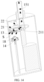
- FIG. 14 is a sectional view of an aerosol-generation system of FIG. 13 along B-B according to some embodiments of the present disclosure.
- the aerosol-generation device also includes an adapter 21.
- the adapter 21 defines an airflow channel 211. One end of the adapter 21 is connected to the suction nozzle 15, and the airflow channel 211 is in communication with the air-outlet channel 151 of the suction nozzle 15.
- the other end of the airflow channel 211 is configured to be in communication with the atomization hole 131 on the rotating element 13 after the receiving groove 132 of the rotating element 13 rotates to the atomization region 183. In this way, the aerosols formed by atomization in the receiving groove 132 may enter the user's mouth through the atomization hole 131, the airflow channel 211, and the air-outlet channel 151 in sequence. It should be noted that, the position of the adapter 21 relative to the suction nozzle 15 is fixed.
- the aerosol-generation article S or the aerosol-generation article residue S' in the receiving groove 132 may be exposed through the atomization hole 131, so that an external force may be applied to the aerosol-generation article residue S' in the receiving groove 132 through the atomization hole 131, and the aerosol-generation article residue S' may fall into the recycling cavity 171.
- the air-outlet channel 151 of the suction nozzle 15 is misaligned with the optical path of the heating assembly 14 along the radial direction of the air-outlet channel 151. That is, the air-outlet channel 151 and the optical path of the heating assembly 14 are not coaxial. Furthermore, the inner wall of the outlet channel 151 may be blacken (such as anodizing). The roughness of the inner wall of the air-outlet channel 151 of suction nozzle 15 is 0.4-3.2 um. In some embodiments, the aperture of the air-outlet channel 151 of the suction nozzle 15 gradually decreases in a direction away from the airflow channel 211, so as to ensure the using safety of the aerosol-generation device.
- the aerosol-generation device may also include a pressing element 22.
- the rotating element 13 is clamped between the pressing element 22 and the bearing plate 18, and the pressing element 22 may apply a force towards the bearing plate 18 on the rotating element 13. In this way, the rotating element 13 may abut against the bearing plate 18 in the rotating process of rotating element 13.
- the pressing element 22 may be arranged directly above the first opening 181 in the direction perpendicular to the plane on which the bearing plate 18 is located, in this way, when the receiving groove 132 of the rotating element 13 rotates to the first opening 181, the rotating element 13 may abut against the bearing plate 18 tightly by using the pressing element 22, so as to prevent too much aerosol-generation articles S in the accommodating cavity 121 from moving out of the accommodating cavity 121. When too much aerosol-generation articles S moves out of the accommodating cavity 121, the rotation of the rotating element 13 may be affected.
- the pressing element 22 may be an element with a roller, so as to avoid affecting the rotation of the rotating element 13.
- the aerosol-generation device may also include a key, a connecting element, a mounting seat, and so on.
- the specific structure and function of these components are the same or similar to the structure and function of the relevant components in the existing aerosol-generation device, and the same or similar technical effects may be achieved. Further details may be referred to the related art and will not be repeated herein.
- the aerosol-generation device it may be controlled that one aerosol-generation article S is heated every time, and single to multiple times of suction may be achieved.
- the aerosol-generation article S may be heated uniformly, the taste experience is uniform and consistent, and a long duration of suction may be achieved after a single filling.
- the accommodating cavity body 12 and/or the recycling cavity body 17 are designed as disposable, the accommodating cavity body 12 may be replaced when the aerosol-generation articles S therein are completely heated. The filling or replacement may be rapidly, and the aerosol-generation article residue S' may be recycled.
- a safe and non-contact heating may be achieved by using the scheme of heating by laser directly, the heating may be completed instantaneously, and the heating may be uniform.
- a miniaturized chip based on laser may reduce the volume of the heating assembly 14, and a miniaturized and commercialized heating device for the aerosol-generation articles S may be obtained.
- the air-outlet channel 151 of the suction nozzle 15 and the optical path of the heating assembly 14 are designed to be non-coaxial, the air-outlet channel 151 may be tapered, the inner wall of the air-outlet channel 151 is blackened, in this way, the safety of the heating assembly 14 in usage may be ensured.
Landscapes
- Containers And Packaging Bodies Having A Special Means To Remove Contents (AREA)
Abstract
Description
- The present disclosure claims priority to
Chinese Patent Application No. 202210195710.9, filed March 1, 2022 - The present disclosure relates to the field of electronic atomization technologies, in particular to an aerosol-generation device and an aerosol-generation system.
- The aerosol-generation device is an appliance for heating and atomizing an aerosol-generation article to form aerosols.
- Currently, heating technologies for the aerosol-generation article mainly include the following schemes: (1) resistance heating in a direct-contact way, (2) induction electromagnetic heating, (3) microwave heating, and so on. The scheme (1) and scheme (2) are both heat-conduction methods, require long waiting time for warm up when using, and may have the problem of non-uniform heating, and the suction experience of the user may be affected. The scheme (3) is radiation heating, the heating occurs simultaneously throughout the entire interior of the aerosol-generation article, and the heating is rapid and uniform. However, the aerosol-generation article is usually filled in the heating cavity as a whole. Since the wavelength of the microwave is long (about 12cm), and has significant fluctuations, it is difficult to heat a specific position, that is, each rapid heating of the aerosol-generation device may heat the aerosol-generation article as a whole to a temperature of about 300-400 °C, resulting in a large change in the taste of the aerosol-generation article in multiple times of suction.
- An aerosol-generation device and an aerosol-generation system are provided in some embodiments of the present disclosure, a uniform heating may be achieved, and the taste of aerosols may be kept fresh and consistent.
- To solve the above technical problem, a technical solution adopted by some embodiments of the present disclosure is to provide an aerosol-generation device. The aerosol-generation device includes an accommodating cavity body, a heating assembly, and a delivering assembly. The accommodating cavity body defines an accommodating cavity. The accommodating cavity is configured to accommodate at least one aerosol-generation article. The delivering assembly configured to deliver an aerosol-generation article of the at least one aerosol-generation article to an atomization region. The heating assembly is configured to heat the aerosol-generation article on the atomization region to generate aerosols.
- To solve the above technical problem, another technical solution adopted by some embodiments of the present disclosure is to provide an aerosol-generation system. The aerosol-generation system includes the aforesaid aerosol-generation device and at least one aerosol-generation article accommodated in the aerosol-generation device.
- In the aerosol-generation device and the aerosol-generation system provided by some embodiments of the present disclosure, the storing position of the at least one aerosol-generation article is different from the atomization region, the at least one aerosol-generation article is delivered to the atomization region in batches through the delivering assembly, and the laser assembly may only heat the aerosol-generation article delivered to the atomization region every time. In this way, the at least one aerosol-generation article may be heated uniformly and quickly, and the atomization utilization rate may be high. In addition, after the atomization of the aerosol-generation article on the atomization region is completed, the aerosol-generation article to be atomized may be delivered to the atomization region for continuous atomization, in this way, the preset number of aerosol-generation articles delivered to the atomization region for atomization may be selected according to the quantity of aerosols corresponding to each suction or several times of suction, so that the taste of aerosols sucked by users may be kept fresh and kept consistent in an early stage and a late stage.
-
-
FIG. 1 is a schematic overall structural view of an aerosol-generation system according to some embodiments of the present disclosure. -
FIG. 2 is a schematic exploded view ofFIG. 1 according to some embodiments of the present disclosure. -
FIG. 3 is a perspective view of an aerosol-generation system other than a shell according to some embodiments of the present disclosure. -
FIG. 4 is a schematic internal structural view of a part of an aerosol-generation system according to some embodiments of the present disclosure. -
FIG. 5 is a schematic view of positional relationships between a rotating element and a bearing plate, an accommodating cavity body, and a recycling cavity body according to some embodiments of the present disclosure. -
FIG. 6 is a schematic view of positional relationships between a rotating element and a bearing plate, an accommodating cavity body, and a recycling cavity body according to some embodiments of the present disclosure. -
FIG. 7 is a schematic view of positional relationships between a rotating element and a bearing plate, an accommodating cavity body, and a recycling cavity body according to some embodiments of the present disclosure. -
FIG. 8 is a schematic structural view of an aerosol-generation system in which a receiving groove of a rotating element is aligned with a first opening according to some embodiments of the present disclosure. -
FIG. 9 is a schematic structural view of an aerosol-generation system in which a rotating element delivers an aerosol-generation article residue to a second opening according to some embodiments of the present disclosure. -
FIG. 10 is a schematic structural view of positional relationships between a rotating element with three receiving grooves and a first opening, a second opening, and an atomization region after the rotating element is rotated by a certain angle according to some embodiments of the present disclosure. -
FIG. 11 is a schematic structural view of positional relationships between the rotating element and the first opening, the second opening, and the atomization region after the rotating element continues to be rotated by a certain angle on the basis ofFIG. 10 . -
FIG. 12 is a schematic internal view of an aerosol-generation system in which a receiving groove of a rotating element is rotated to another position different from a second opening according to some embodiments of the present disclosure. -
FIG. 13 is a view of a positional relationship between a rotating element and an adapter after a receiving groove of the rotating element is rotated to an atomization region according to some embodiments of the present disclosure. -
FIG. 14 is a sectional view of an aerosol-generation system ofFIG. 13 along B-B according to some embodiments of the present disclosure. - Illustration of reference numbers: aerosol-generation article S; aerosol-generation article S';
shell 11;main body 111;cover 112; accommodatingcavity body 12;accommodating cavity 121; rotatingelement 13;atomization hole 131; receivinggroove 132;heating assembly 14;suction nozzle 15; air-outlet channel 151;first driving element 16;recycling cavity body 17;recycling cavity 171;bearing plate 18; first opening 181;second opening 182;atomization region 183;sealing cover 19;second driving element 20;adapter 21;airflow channel 211;pressing element 22. - The technical solutions in the embodiments of the present disclosure are clearly and completely described below with reference to the accompanying drawings in the embodiments of the present disclosure. Apparently, the described embodiments are merely some rather than all of the embodiments of the present disclosure. All other embodiments obtained by those skilled in the art based on the embodiments of the present disclosure without creative efforts shall fall within the protection scope of the present disclosure.
- The terms "first", "second", and "third" in the embodiments of the present disclosure are only used for descriptive purposes, and cannot be understood as indicating or implying relative importance or implicitly indicating the number of indicated technical features. Thus, the features defined with "first", "second", and "third" may explicitly or implicitly include at least one of the features. In the description of the present application, "a plurality of" means at least two, e.g., two, three, etc., unless specifically defined otherwise. All directional indications (such as up, down, left, right, front, back) in the embodiments of the present disclosure are only configured to account for relative positional relationships, motion conditions, etc., between components in a particular orientation (as shown in the drawings), if the particular orientation changed, correspondingly changes the directional indications. In addition, the terms "including" and "having" and any variations thereof are intended to cover non-exclusive inclusions. For example, a process, method, system, product, or device that includes a series of steps or units is not limited to the listed steps or units, but optionally includes unlisted steps or units, or optionally also includes other steps or units inherent to these processes, methods, products or equipment.
- Mentioning "embodiments" herein means that a specific feature, structure, or characteristic described in conjunction with the embodiments may be included in at least one embodiment of the present disclosure. The appearances of the phrase in various places in the specification are not necessarily all referring to the same embodiment, nor are separate or alternative embodiments mutually exclusive of other embodiments. It is explicitly and implicitly understood by those skilled in the art that the embodiments described herein may be combined with other embodiments.
- The present disclosure will be described in detail below in combination with the drawings and embodiments.
-
FIG. 1 is a schematic overall structural view of an aerosol-generation system according to some embodiments of the present disclosure.FIG. 2 is a schematic exploded view ofFIG. 1 according to some embodiments of the present disclosure.FIG. 3 is a perspective view of an aerosol-generation system other than a shell according to some embodiments of the present disclosure. As shown inFIGS. 1 to 3 , in some embodiments, an aerosol-generation system is provided. The aerosol-generation system includes an aerosol-generation device and at least one aerosol-generation article S accommodated in the aerosol-generation device. - The aerosol-generation device is configured to heat the at least one aerosol-generation article S by laser, so as to form aerosols for a user to suck. The at least one aerosol-generation article S may be a solid substrate, which may include plant leaves such as vanilla leaves, tea leaves, and mint leaves, and may include one or more kinds of powders, particles, fragments, thin strips, strips, and sheets. In some embodiments, the solid substrate may include additional volatile aroma compounds, and the volatile aroma compounds may be released when the substrate is heated. In some embodiments, the at least one aerosol-generation article S may also be a liquid substrate, such as oils and medicinal liquids with aroma components added. In the following embodiments, the at least one aerosol-generation article S may be illustrated as the solid substrate for example.
- In some embodiments, the at least one aerosol-generation article S includes a plurality of aerosol-generation articles S. Each of the plurality of aerosol-generation articles S is in the shape of a sheet, and the plurality of aerosol-generation articles S are stacked with each other. In this way, the density of the aerosol-generation articles S may be increased, the accommodating quantity of the aerosol-generation articles S in a fixed volume may be increased, and the storage quantity of aerosol-generation articles S in the aerosol-generation device may be increased. In this way, a long duration of suction of the aerosol-generation device may be achieved after a single filling. In some embodiments, the thickness of each aerosol-generation article S is 0.2-2mm. In some embodiments, the thickness of each aerosol-generation article S is 0.5-1mm. In some embodiments, 30 or more aerosol-generation articles S may be accommodated in the aerosol-generation device. Each aerosol-generation article S may be heated for one to five times to support a single suction, so as to ensure the consistency of the aerosols generated by atomization. In this way, after a single filling, the aerosol-generation device may be sucked by more than 30 times, or even more than 100 times, and the taste of the aerosols is long-term effective and consistent.
- In some embodiments, the diameter of each aerosol-generation article S may be 2-15mm. In some embodiments, the surface of each aerosol-generation article S may be provided with a through hole, and the diameter the through hole and the filling ratio of each aerosol-generation article S may be designed according to different airflow-resistance requirements, so to ensure the release of aerosols.
- The specific structure and function of the aerosol-generation device may be seen in any one of the following embodiments.
- As shown in
FIGS. 2 and3 , the aerosol-generation device includes ashell 11, anaccommodating cavity body 12 arranged in theshell 11, a delivering assembly arranged in theshell 11, aheating assembly 14 arranged in theshell 11, and asuction nozzle 15. - The
shell 11 may include amain body 111 and acover 112. Thecover 112 is covered on themain body 111. Themain body 111 and thecover 112 cooperatively form a hollow body and are configured as the outer surface of the aerosol-generation device, which is configured to protect assemblies in the hollow body. In some embodiments, theshell 11 may also be assembled by engaging a left portion and a right portion together or engaging a front portion and a rear portion together, and the present disclosure does not limit the structure of theshell 11. Theaccommodating cavity body 12, the delivering assembly, and theheating assembly 14 are housed in the hollow body. Thesuction nozzle 15 is arranged on theshell 11 and defines an air-outlet channel 151. The air-outlet channel 151 is configured to be in communication with external atmosphere. The user may suck the aerosols formed by atomization through thesuction nozzle 15. In some embodiments, thesuction nozzle 15 may also be directly defined by theshell 11. In some embodiments, thesuction nozzle 15 is a cylindrical tube inserted in a through hole on the top wall of themain body 111. - As shown in
FIG.3 , theaccommodating cavity body 12 defines anaccommodating cavity 121. Theaccommodating cavity 121 is configured to accommodate the plurality of aerosol-generation articles S. That is, the plurality of aerosol-generation articles S in the aerosol-generation system are stacked with each other along a depth direction of theaccommodating cavity 121. In some embodiments, theaccommodating cavity body 12 is a structure independent from theshell 11, and is detachably connected to theshell 11, in this way, theaccommodating cavity body 12 is disposable. After the accommodated aerosol-generation articles S are completely heated, it is convenient to take out theaccommodating cavity body 12, and new aerosol-generation articles S may be filled rapidly. In some embodiments, another newaccommodating cavity body 12 with aerosol-generation articles S may be replaced, so as to improve the replaceability of theaccommodating cavity body 12. - The
accommodating cavity 121 may be cylindrical. The peripheral shape of theaccommodating cavity 121 may match the peripheral shape of each aerosol-generation article S, and the diameter of theaccommodating cavity 121 may be equal to or slightly greater than the diameter of each aerosol-generation article S, so as to prevent the aerosol-generation articles S from shaking in theaccommodating cavity 121, and it is easy for the aerosol-generation article S to be filled in theaccommodating cavity 121 or to be moved out of theaccommodating cavity 121. In some embodiments, the material of theaccommodating cavity body 12 may be harmless metal materials, such as aluminum alloy of series 6, stainless steel, etc., or harmless plastic materials, such as polyetheretherketone (PEEK), etc. - As shown in
FIG.3 , the delivering assembly is configured to deliver the aerosol-generation articles S to anatomization region 183 in batches. When the at least one aerosol-generation article S includes a plurality of aerosol-generation articles S stacked with each other, the delivering assembly is configured to deliver the plurality of aerosol-generation articles S to theatomization region 183 in sequence. That is, the delivering assembly delivers a preset number of aerosol-generation articles S to theatomization region 183 every time, rather than delivers all the aerosol-generation articles S in theaccommodating cavity 121 to theatomization region 183 at one time. It may be understood that, when the at least one aerosol-generation article S is a liquid substrate, it may be controlled that a part of the aerosol-generation article S flows from theaccommodating cavity 121 to the delivering assembly every time, or the delivering assembly may take a part of the aerosol-generation article S out of theaccommodating cavity 121 and deliver the part of the aerosol-generation article S to theatomization region 183, so as to deliver the aerosol-generation article S in theaccommodating cavity 121 to theatomization region 183 by several times. - In some embodiments, as shown in
FIG. 2 or3 , the delivering assembly may include arotating element 13, a power element (which is not shown in drawings), and a control circuit (which is not shown in drawings). Therotating element 13 is connected to the power element. The power element is configured to drive the rotatingelement 13 to rotate, so as to deliver the aerosol-generation article S to theatomization region 183 through the rotation of therotating element 13. Therotating element 13 may be a rotatable plate, a movable machine arm, a movable machine hand, etc. The power element may be a motor, a pump, etc. In some embodiments, the rotatingelement 13 may also be driven by a manual mechanical mechanism. For example, a part of therotating element 13 may be extended out of theshell 11 and may be rotated manually, in this way, the usage of the power element may be reduced, and the volume of the aerosol-generation device may be reduced. The control circuit is electrically connected to the power element and theheating assembly 14 respectively. The control circuit is configured to control the power element to enable therotating element 13 to move the aerosol-generation article S to theatomization region 183, and control theheating assembly 14 to heat the aerosol-generation article S on theatomization region 183 after therotating element 13 delivers the aerosol-generation article S to theatomization region 183. The control circuit may be powered by a built-in battery assembly. In some embodiments, the control circuit may further be configured to control theheating assembly 14 to output continuous laser or pulse laser, and may control a power output curve of a single suction, so as to improve the experience effect of aerosols. - As shown in
FIGS 2 and3 , theheating assembly 14 is configured to heat the aerosol-generation article S on theatomization region 183. For example, theheating assembly 14 may adopt thermal-radiation heating methods such as laser heating, microwave heating, infrared heating, and so on. Since the thermal-radiation heating methods has characteristics of non-contact and instantaneous heating, a heat-not-burn technical scheme of the aerosol-generation article S may be achieved. The heat-not-burn technical scheme is safe and may reduce hazard. Theheating assembly 14 is illustrated by using laser heating as an example, but is not limited by the embodiments of present disclosure. Theheating assembly 14 may be configured to transmit laser, and the laser is configured to heat the aerosol-generation article S on theatomization region 183 to generate aerosols. - The
heating assembly 14 may include a semiconductor laser chip. The semiconductor laser chip may be an Edge-Emitting semiconductor laser chip or a Vertical-Cavity Surface-Emitting semiconductor laser chip, which is made of gallium arsenide or indium phosphide. In some embodiments, an Edge-Emitting Laser (EEL) chip or a Vertical-Cavity Surface-Emitting Laser (VCSEL) chip, which is a Transistor Outline (TO) package or a Quad Flat No-leads (QFN) package, may be adopted. The semiconductor laser chip with a hermetic package may improve the stability and reliability of the aerosol-generation device in long-term operation. In some embodiments, the package body may adopt a passive conductive cooling scheme. For example, the TO or QFN package structure is directly packaged on a heat sink to assist the heat dissipation of the laser-transmitting module, and the heat sink may be made of metal. In some embodiments, the aerosol-generation device may also include a heat-dissipation element (which is not shown in drawings). The heat-dissipation element may be arranged at the upstream of theheating assembly 14 along the airflow path of the aerosol-generation device and configured to dissipate heat for theheating assembly 14. The heat-dissipation element may be heat-dissipation fins. The heat sink and heat-dissipation fins are made of materials with high thermal conductivity and high heat capacity, such as copper and aluminum. In some embodiments, the laser-package module is fixed to the metal heat-dissipation fins by a curable silver glue or a metal solder which is certified by ROHS (Restriction of Hazardous Substances Directive). - The output peak power of the semiconductor laser chip is 1-30W. The wavelength of the semiconductor laser chip is 800-1500nm. The wavelength of the laser transmitted by the semiconductor laser chip used in the embodiments of present disclosure is around 800-1500nm, the laser has obvious particle characteristics, and the quality and directionality of the laser beam are great. Therefore, based on typical physical characteristics of the laser, the aerosol-generation article S may be heated by the laser rapidly. Furthermore, due to optical characteristics of the laser, the aerosol-generation article S may be heated selectively and without directly contact, and the taste of aerosols may be kept fresh and stable. Compared with other heating methods, the laser heating does not need specialized laser shielding element, the structure is simple, and the cost is low. In some embodiments, the volume of the semiconductor laser chip is less than 4cm3, the volume of the
heating assembly 14 is reduced, and a miniaturized and commercialized heating device for the aerosol-generation articles S may be obtained. - In some embodiments, the diameter of the light spot formed by the laser on the surface of the aerosol-generation article S is substantially equal to the diameter of each aerosol-generation article S. The energy distribution of the light spot is in a TOP-HAT mode. In this way, the uniformity of light energy is greater than 70%, and the heating may be uniform.
- In the aerosol-generation device provided by some embodiments of the present disclosure, an
accommodating cavity body 12 is provided, theaccommodating cavity body 12 defines anaccommodating cavity 121, so as to receive at least one aerosol-generation article S through theaccommodating cavity 121. A delivering assembly is further provided, and the delivering assembly is configured to deliver an aerosol-generation article S of the at least one aerosol-generation article S to anatomization region 183 in batches. Aheating assembly 14 is further provided, and theheating assembly 14 is configured to transmit a laser, so as to heat the aerosol-generation article S on theatomization region 183 by the laser. The aerosol-generation article S is heated by the laser. Since the laser has characteristics of non-contact and instantaneous heating, a heat-not-burn technical scheme of the aerosol-generation article S may be achieved. The heat-not-burn technical scheme is safe and may reduce hazard. In addition, the storing position of the at least one aerosol-generation article S is different from theatomization region 183, the at least one aerosol-generation article S is delivered to theatomization region 183 in batches through the delivering assembly, and theheating assembly 14 may only heat the aerosol-generation article S delivered to theatomization region 183 every time. In this way, the preset number of aerosol-generation articles S for each heating may be selected according to the actual wavelength of the laser, the possibility that the laser is absorbed by the at least one aerosol-generation article S due to the wavelength characteristics of the laser may be reduced, the at least one aerosol-generation article S may be heated uniformly, and the atomization utilization rate may be high. When the laser is absorbed by the at least one aerosol-generation article S, the aerosol-generation article S far from theheating assembly 14 cannot be heated effectively. After the atomization of the aerosol-generation article S on theatomization region 183 is completed, the aerosol-generation article S to be atomized may be delivered to theatomization region 183 for continuous atomization. In this way, the preset number of aerosol-generation articles S delivered to theatomization region 183 for atomization may be selected according to the quantity of aerosols corresponding to each suction or several times of suction, so that the taste of aerosols sucked by users may be kept fresh and kept consistent in an early stage and a late stage. - As shown in
FIG. 3 , the aerosol-generation device also includes afirst driving element 16. Thefirst driving element 16 is arranged in theaccommodating cavity 121, and is configured to drive the plurality of aerosol-generation articles S in theaccommodating cavity 121 to move out of theaccommodating cavity 121 in sequence. Whether the aerosol-generation device is in a horizontal position or a non-horizontal position, it may be ensured that the aerosol-generation articles S in theaccommodating cavity 121 may be moved out of theaccommodating cavity 121 under the driving force of thefirst driving element 16. In some embodiments, thefirst driving element 16 may drive one aerosol-generation article S to move out of theaccommodating cavity 121 every time. In some embodiments, the delivering assembly is further configured to deliver the aerosol-generation article S moved out of theaccommodating cavity 121 to theatomization region 183. - In some embodiments, the
first driving element 16 is an elastic element arranged between the bottom wall of theaccommodating cavity body 12 and the plurality of aerosol-generation articles S. For example, the elastic element may be a spring, a torsion spring, and so on. In some embodiments, thefirst driving element 16 may also be a rotating shaft or a piston connected to a driving source, such as a motor, a pump, and so on. The driving source may drive thefirst driving element 16, and thefirst driving element 16 may drives one aerosol-generation article S to move out of theaccommodating cavity 121 every time. - After the aerosol-generation article S is completely heated, that is, after the aerosol-generation article S is completely atomized, an aerosol-generation article residue S' may be formed. In order to avoid the impact of the aerosol-generation article residue S' on the atomization effect of the aerosol-generation article S delivered to the
atomization region 183 subsequently, the delivering assembly is further configured to remove the aerosol-generation article residue S' from theatomization region 183. The aerosol-generation article residue S' may be an outer package of the aerosol-generation article S, such as aluminum foil and so on. It may be understood that, if the aerosol-generation article S is a liquid substrate, there is substantially no aerosol-generation article residue S', and the removing operation is not needed. While a recycling container is needed to be arranged on theatomization region 183 to recycle the liquid substrate. - In some embodiment, as shown in
FIGS 2 and3 , in order to recycle the aerosol-generation article residue S', the aerosol-generation device also includes arecycling cavity body 17. Therecycling cavity body 17 defines arecycling cavity 171. The delivering assembly delivers the aerosol-generation article residue S' from theatomization region 183 to therecycling cavity 171 for recycling. - The
recycling cavity body 17 is a structure independent from theshell 11, and is detachably connected to theshell 11. In this way, therecycling cavity body 17 may be disposable. After therecycling cavity 171 is full, therecycling cavity body 17 may be replaced environmental friendly and rapidly. In some embodiments, therecycling cavity body 17 and theaccommodating cavity body 12 may be arranged side by side along the radial direction of theshell 11, so as to reduce the volume of the aerosol-generation system. In some embodiments, therecycling cavity 171 may also be cylindrical. The peripheral shape of therecycling cavity 171 may match the peripheral shape of the aerosol-generation article residue S'. The diameter of therecycling cavity 171 may be substantially equal to or slightly greater than the diameter of the aerosol-generation article residue S', so that the aerosol-generation article residue S' may fall into therecycling cavity 171. In some embodiments, the material of therecycling cavity body 17 may be harmless metal materials, such as aluminum alloy of series 6, stainless steel, etc., or harmless plastic materials, such as PEEK, etc. Therecycling cavity body 17 may be integrated with theaccommodating cavity body 12, and two different cavities are needed to be defined. In some embodiments, theaccommodating cavity body 12 and/or therecycling cavity body 17 may also be constructed by theshell 11, that is, theaccommodating cavity 121 and/or therecycling cavity 171 are directly defined by theshell 11. - As shown in
FIGS. 2 to 4 ,FIG. 4 is a schematic internal structural view of a part of an aerosol-generation system according to some embodiments of the present disclosure. The aerosol-generation device also includes a bearingplate 18. A surface of the bearingplate 18 facing thesuction nozzle 15 defines theatomization region 183, so as to support the aerosol-generation article S. The bearingplate 18 may be made of metals or plastics which are safe and non-toxic. - In some embodiments, as shown in
FIG. 4 , theaccommodating cavity body 12 and therecycling cavity body 17 are both located on a side of the bearingplate 18 away from thesuction nozzle 15, so as to reduce the volume of the aerosol-generation device. In some embodiments, in order to ensure that the aerosol-generation article S in theaccommodating cavity 121 may move to theatomization region 183 of the bearingplate 18, the bearingplate 18 defines afirst opening 181 in communication with theaccommodating cavity 121, so that the aerosol-generation article S in theaccommodating cavity 121 may reach the side of the bearingplate 18 facing thesuction nozzle 15 through thefirst opening 181. In some embodiments, the bearingplate 18 defines asecond opening 182 in communication with therecycling cavity 171, so that the aerosol-generation article residue S' may enter therecycling cavity 171 through thesecond opening 182. In this way, the aerosol-generation article S may be prevented from falling to other positions of the aerosol-generation device in a moving process, and waste or pollution may be avoided. In some embodiments, thefirst opening 181 faces theaccommodating cavity 121 along a length direction of theshell 11, and thesecond opening 182 faces therecycling cavity 171 along the length direction of theshell 11. - In some embodiments, as shown in
FIGS. 2 to 4 , in order to facilitate the assembly of the aerosol-generation device and reduce the volume of the aerosol-generation device, theheating assembly 14 and theaccommodating cavity body 12 are located on the same side of the bearingplate 18, and the part of the bearingplate 18 corresponding to theatomization region 183 is made of an optical transparent material. In this way, theheating assembly 14 may directly irradiate and heat the aerosol-generation article S on theatomization region 183 through the bearingplate 18. Compared with other heating methods in which a heat-conduction medium is heated firstly, and then the aerosol-generation article S is heated through the heat conduction of the heat-conduction medium, the aerosol-generation device in the embodiments of present disclosure may achieve non-contact heating, the heating is safe and may be completed instantaneously, and the heating may be uniform. The optical transparent material may be fused silica or sapphire. In some embodiments, theheating assembly 14 may also be arranged on the side of the bearingplate 18 towards thesuction nozzle 15, the bearingplate 18 may not block the laser, and the material of the part of the bearingplate 18 corresponding to theatomization region 183 is not limited. - In some embodiments, the rotating
element 13 may be in the shape of a plate, and may be rotatably connected to the surface of the bearingplate 18 facing thesuction nozzle 15, so as to move the aerosol-generation article S outside theaccommodating cavity 121 to theatomization region 183 along the surface of the bearingplate 18, and move the aerosol-generation article residue S' from theatomization region 183 to therecycling cavity 171. - In some embodiments, as shown in
FIGS. 2 ,3 and5, FIG. 5 is a schematic view of positional relationships between arotating element 13 and a bearingplate 18, anaccommodating cavity body 12, and arecycling cavity body 17 according to some embodiments of the present disclosure. The surface of therotating element 13 facing the bearingplate 18 defines at least one receivinggroove 132, and the bottom wall or side wall of each of the at least one receivinggroove 132 defines anatomization hole 131. The at least one receivinggroove 132 is configured to receive the aerosol-generation article S outside theaccommodating cavity 121 and limit the position of the aerosol-generation article S outside theaccommodating cavity 121. In a rotating process, the rotatingelement 13 fixes the aerosol-generation article S through the receivinggroove 132, moves the aerosol-generation article S to theatomization region 183, and moves the aerosol-generation article residue S' in the receivinggroove 132 formed by atomization from theatomization region 183 to thesecond opening 182, in this way, the aerosol-generation article residue S' may fall into therecycling cavity 171. Theatomization hole 131 is in communication with the receivinggroove 132, the aerosol-generation article S in the receivinggroove 132 is moved to theatomization region 183 for atomization, and the generated aerosols flows out through theatomization hole 131. As shown inFIG. 5 , theatomization hole 131 includes several micropores spaced apart from each other, in this way, the aerosols may flow out of the receivinggroove 132 and enter the air-outlet channel 151. The bottom wall of the receivinggroove 132 may be directly used to shield the laser, so as to reduce the possibility that the highly-directional laser overflows from theshell 11 and reduce personnel-security risk. At the same time, a laser-shielding element is not needed, the structure may be simple, and the cost may be low. In some embodiments, as shown inFIG. 6, FIG. 6 is a schematic view of positional relationships between arotating element 13 and a bearingplate 18, anaccommodating cavity body 12, and arecycling cavity body 17 according to some embodiments of the present disclosure. The diameter of theatomization hole 131 may be slightly less than the diameter of the receivinggroove 132. That is, the diameter of theatomization hole 131 may be slightly less than the diameter of the aerosol-generation article S. Theatomization hole 131 is a large single through hole. The receivinggroove 132 may limit the position of the aerosol-generation article S. An external force may be applied to the aerosol-generation article residue S' in the receivinggroove 132 through thelarge atomization hole 131, and the aerosol-generation article residue S' may fall from the receivinggroove 132. - In some embodiments, the depth of the receiving
groove 132 may be equal to the thickness of one aerosol-generation article S. In this way, it is ensured that only one aerosol-generation article S enters the receivinggroove 132 every time, and one aerosol-generation article S is delivered by the rotatingelement 13 every time. In this way, theheating assembly 14 only heats and atomizes one aerosol-generation article S every time. After the user sucks 1-5 times, the aerosol-generation article S is completely heated, a new aerosol-generation article S may be atomized, in this way, the taste of aerosols in an early stage and a late stage of the user's suction may be kept consistent. Furthermore, it may be ensured that the laser with short wavelength will not be absorbed by the aerosol-generation article S in the heating process of the aerosol-generation article S, the heating uniformity and the atomization efficiency may be improved, and the taste of aerosols may be kept fresh and kept consistent in an early stage and a late stage. - In some embodiments, the depth of the receiving
groove 132 may also be equal to the thickness of two or three aerosol-generation articles S, which may be set according to the penetration distance of the laser and the user's needs. For example, the thickness of the aerosol-generation article S may be small, and the total thickness of several aerosol-generation articles S is equal to the penetration distance of the laser. In this way, several aerosol-generation articles S with different flavors and stacked with each other may be pushed into the receivinggroove 132 every time, and then be delivered to theatomization region 183 for heating and atomization, and the user's suction experience may be enriched. - As shown in
FIG. 7, FIG. 7 is a schematic view of positional relationships between arotating element 13 and a bearingplate 18, anaccommodating cavity body 12, and arecycling cavity body 17 according to some embodiments of the present disclosure. After the receivinggroove 132 is moved away from thefirst opening 181, in order to prevent the aerosol-generation articles S in theaccommodating cavity 121 from being ejected out of theaccommodating cavity 121 under the drive of thefirst driving element 16, the rotatingelement 13 may block thefirst opening 181 when other positions of rotatingelement 13 except for thefirst opening 181 is aligned with the receivinggroove 132. In this way, the aerosol-generation articles S in theaccommodating cavity 121 cannot be moved out of theaccommodating cavity 121 under the block of therotating element 13. - The rotating process of the
rotating element 13 may be described as follows. As shown inFIGS. 5 and8, FIG. 8 is a schematic structural view of an aerosol-generation system in which a receivinggroove 132 of arotating element 13 is aligned with afirst opening 181 according to some embodiments of the present disclosure. When the receivinggroove 132 of therotating element 13 is aligned with thefirst opening 181, as shown inFIGS. 5 and8 , the acting force of therotating element 13 on the aerosol-generation article S in theaccommodating cavity 121 disappears, and the aerosol-generation article S in theaccommodating cavity 121 may be moved out of theaccommodating cavity 121 under the action of thefirst driving element 16 and may be received in the receivinggroove 132. Therotating element 13 starts to rotate and delivers the aerosol-generation article S received in the receivinggroove 132, as shown inFIG. 2 , the aerosol-generation article S received in the receivinggroove 132 may be moved to theatomization region 183 for atomization with the rotation of therotating element 13, at this time, thefirst opening 181 may be blocked by the rotatingelement 13. As shown inFIG. 9, FIG. 9 is a schematic structural view of an aerosol-generation system in which arotating element 13 delivers an aerosol-generation article residue S' to asecond opening 182 according to some embodiments of the present disclosure. After the aerosol-generation article S in the receivinggroove 132 is completely heated and the aerosol-generation article residue S' is formed, the rotatingelement 13 continues to rotate and delivers the aerosol-generation article residue S' to thesecond opening 182. When the receivinggroove 132 is aligned with thesecond opening 182, the aerosol-generation article residue S' receive in the receivinggroove 132 may fall from the receivinggroove 132 to therecycling cavity 171 through thesecond opening 182 for recycling. At this time, thefirst opening 181 may be still blocked by rotatingelement 13. Then therotating element 13 rotates in an opposite direction, and the receivinggroove 132 of therotating element 13 is moved to face thefirst opening 181. Another aerosol-generation article S in theaccommodating cavity 121 may be moved out of theaccommodating cavity 121 under the action of thefirst driving element 16 and may be received in the receivinggroove 132. - In some embodiments, as shown in
FIGS. 2 ,8 and 9 , the rotatingelement 13 defines only one receivinggroove 132. Therotating element 13 is in the shape of a sector, and therotating element 13 may rotate around an end or an edge of the sector. The radian of therotating element 13 is not less than the radian of the rotating path of therotating element 13 between thefirst opening 181 and thesecond opening 182. In this way, it may be ensured that when the receivinggroove 132 of therotating element 13 is aligned with thesecond opening 182, thefirst opening 181 may be still blocked by the rotatingelement 13, so as to reduce the possibility that the aerosol-generation article S in theaccommodating cavity 121 is moved to a position outside the receivinggroove 121 under the driving force of thefirst driving element 16. The following embodiments may use the aforesaid features as an example. In some embodiments, the rotatingelement 13 may rotate along the following path. The receivinggroove 132 of therotating element 13 rotates from the position of thefirst opening 181 shown inFIG. 8 to theatomization region 183 shown inFIG. 2 in a counterclockwise direction, and then rotates to the position of thesecond opening 182 shown inFIG. 9 in the counterclockwise direction. Subsequently, the receivinggroove 132 of therotating element 13 rotates to the position of thefirst opening 181 through theatomization region 183 shown inFIG. 2 in a clockwise direction, so as to continue to receive the aerosol-generation article S in theaccommodating cavity 121. - In some embodiments, the rotating
element 13 may be in the shape of a disc, and therotating element 13 may rotate around the center of the disc. When the receivinggroove 132 of therotating element 13 is moved to any position different from thefirst opening 181, the rotatingelement 13 may always block thefirst opening 181. Therotating element 13 may rotate continuously in the same direction, and the rotation direction of therotating element 13 is not limited by the present disclosure. - As shown in
FIGS. 10 to 11, FIG. 10 is a schematic structural view of positional relationships between a rotating element with three receiving grooves and a first opening, a second opening, and an atomization region after the rotating element is rotated by a certain angle according to some embodiments of the present disclosure.FIG. 11 is a schematic structural view of positional relationships between the rotating element and the first opening, the second opening, and the atomization region after the rotating element continues to be rotated by a certain angle on the basis ofFIG. 10 . In some embodiments, the rotatingelement 13 may include at least three receivinggrooves 132. The at least three receivinggrooves 132 are spaced apart from each other along the rotating path of therotating element 13. A distance between any adjacent two of the at least three receivinggrooves 132 along the rotating path of therotating element 13 may be equal to a distance between any adjacent two of thefirst opening 181, theatomization region 183, and thesecond opening 182 along the rotating path of therotating element 13. - As shown in
FIG. 10 , in some embodiments, the rotatingelement 13 may define three receivinggrooves 132. The three receivinggrooves 132 may include two groups of receivinggrooves 132. Each of the two groups of receivinggrooves 132 may include two adjacent receivinggrooves 132. A distance between two adjacent receivinggrooves 132 of one of the two groups of receivinggrooves 132 along the rotating path of therotating element 13 may be equal to a distance between thefirst opening 181 and theatomization region 183 along the rotating path of therotating element 13, and a distance between two adjacent receivinggrooves 132 of the other of the two groups of receivinggrooves 132 along the rotating path of therotating element 13 may be equal to a distance between theatomization region 183 and thesecond opening 182 along the rotating path of therotating element 13. Compared with the scheme in which therotating element 13 only defines one receivinggroove 132, there is no need to rotate therotating element 13 back and forth to deliver a next aerosol-generation article S.FIGS. 10 to 11 illustrate a counterclockwise direction rotation, and therotating element 13 may rotate in the same direction all the time. When one of the three receivinggrooves 132 is moved to theatomization region 183, anext receiving groove 132 may be rotated to the position of thefirst opening 181 to receive a new aerosol-generation article S. When the aerosol-generation article S on theatomization region 183 is completely heated and rotates towards thesecond opening 182, the receivinggroove 132 receiving the new aerosol-generation article S may rotates towards theatomization region 183 to atomize the new aerosol-generation article S, and so on. In this way, the atomization efficiency may be improved, and the energy may be utilized sufficiently. - In some embodiments, as shown in
FIG. 12, FIG. 12 is a schematic internal view of an aerosol-generation system in which a receivinggroove 132 of arotating element 13 is rotated to another position different from asecond opening 182 according to some embodiments of the present disclosure. If therotating element 13 is in the shape of a sector, thesecond opening 182 is always exposed when the receivinggroove 132 of therotating element 13 is located at another position different from thesecond opening 182. In order to prevent the aerosol-generation article residue S' in therecycling cavity body 17 from being leaked or the waste gas in therecycling cavity body 17 from being escaped, as shown inFIGS. 2 or3 , the aerosol-generation device may also include a sealingcover 19 and asecond driving element 20. The sealingcover 19 may be configured to switch between a first position and a second position different from the first position. The sealingcover 19 covers thesecond opening 182 when being on the first position, and exposes thesecond opening 182 when being on the second position. Thesecond driving element 20 is connected to the sealingcover 19, and is configured to drive the sealingcover 19 to move from the second position to the first position. In some embodiments, the sealingcover 19 may also be driven manually to switch between the first position and the second position. The driving force for the sealingcover 19 to move from the first position to the second position may be provided by the rotating force of therotating element 13. - The second position may be any position which is spaced apart from the
second opening 182 along a direction parallel to the bearingplate 18, or any position which is spaced apart from thesecond opening 182 along a direction perpendicular to the bearingplate 18. In some embodiments, the second position may be directly above thesecond opening 182, and the sealingcover 19 may moves along a direction perpendicular to the surface of the bearingplate 18 to be located on the first position or the second position. Thesecond driving element 20 may be a motor, a pump, an elastic component, and so on. It may be understood that, if the second position is any position spaced apart from thesecond opening 182 in the direction parallel to the bearingplate 18, the rotatingelement 13 swings back and forth around a central axis. - In some embodiments, the sealing
cover 19 moves along a direction perpendicular to the plane on which thebearing plate 18 is located to switch between the first position and the second position. When the receivinggroove 132 of therotating element 13 moves towards thesecond opening 182, the sealingcover 19 moves away from thesecond opening 182. When the receivinggroove 132 of therotating element 13 moves towards thesecond opening 182, the sealingcover 19 moves close to thesecond opening 182, and a part of the sealingcover 19 may pass through theatomization hole 131 and contact the aerosol-generation article residue S' in the receivinggroove 132. Thesecond driving element 20 may continue to drive the sealingcover 19 to move towards the first position, and the aerosol-generation article residue S' in the receivinggroove 132 may move towards therecycling cavity 171 under the driving force and then fall into therecycling cavity 171 for recycling. In this way, the possibility that the aerosol-generation article residue S' in the receivinggroove 132 is stuck in the receivinggroove 132 and is unable to fall off may be reduced. - In some embodiments, as shown in
FIGS. 2 ,13 and14 ,FIG. 13 is a view of a positional relationship between arotating element 13 and anadapter 21 after a receivinggroove 132 of therotating element 13 is rotated to anatomization region 183 according to some embodiments of the present disclosure.FIG. 14 is a sectional view of an aerosol-generation system ofFIG. 13 along B-B according to some embodiments of the present disclosure. The aerosol-generation device also includes anadapter 21. Theadapter 21 defines anairflow channel 211. One end of theadapter 21 is connected to thesuction nozzle 15, and theairflow channel 211 is in communication with the air-outlet channel 151 of thesuction nozzle 15. The other end of theairflow channel 211 is configured to be in communication with theatomization hole 131 on therotating element 13 after the receivinggroove 132 of therotating element 13 rotates to theatomization region 183. In this way, the aerosols formed by atomization in the receivinggroove 132 may enter the user's mouth through theatomization hole 131, theairflow channel 211, and the air-outlet channel 151 in sequence. It should be noted that, the position of theadapter 21 relative to thesuction nozzle 15 is fixed. When the receivinggroove 132 of therotating element 13 rotates to another position different from theatomization region 183, the aerosol-generation article S or the aerosol-generation article residue S' in the receivinggroove 132 may be exposed through theatomization hole 131, so that an external force may be applied to the aerosol-generation article residue S' in the receivinggroove 132 through theatomization hole 131, and the aerosol-generation article residue S' may fall into therecycling cavity 171. - In some embodiments, in order to ensure that the highly-directional laser cannot overflow from the
shell 11 and that personal-security risk is avoided, as shown inFIG. 14 , the air-outlet channel 151 of thesuction nozzle 15 is misaligned with the optical path of theheating assembly 14 along the radial direction of the air-outlet channel 151. That is, the air-outlet channel 151 and the optical path of theheating assembly 14 are not coaxial. Furthermore, the inner wall of theoutlet channel 151 may be blacken (such as anodizing). The roughness of the inner wall of the air-outlet channel 151 ofsuction nozzle 15 is 0.4-3.2 um. In some embodiments, the aperture of the air-outlet channel 151 of thesuction nozzle 15 gradually decreases in a direction away from theairflow channel 211, so as to ensure the using safety of the aerosol-generation device. - In some embodiments, as shown in
FIG. 2 ,3 or14 , the aerosol-generation device may also include apressing element 22. Therotating element 13 is clamped between thepressing element 22 and the bearingplate 18, and thepressing element 22 may apply a force towards the bearingplate 18 on therotating element 13. In this way, the rotatingelement 13 may abut against the bearingplate 18 in the rotating process of rotatingelement 13. In some embodiments, thepressing element 22 may be arranged directly above thefirst opening 181 in the direction perpendicular to the plane on which thebearing plate 18 is located, in this way, when the receivinggroove 132 of therotating element 13 rotates to thefirst opening 181, the rotatingelement 13 may abut against the bearingplate 18 tightly by using thepressing element 22, so as to prevent too much aerosol-generation articles S in theaccommodating cavity 121 from moving out of theaccommodating cavity 121. When too much aerosol-generation articles S moves out of theaccommodating cavity 121, the rotation of therotating element 13 may be affected. Thepressing element 22 may be an element with a roller, so as to avoid affecting the rotation of therotating element 13. - In some embodiments, the aerosol-generation device may also include a key, a connecting element, a mounting seat, and so on. The specific structure and function of these components are the same or similar to the structure and function of the relevant components in the existing aerosol-generation device, and the same or similar technical effects may be achieved. Further details may be referred to the related art and will not be repeated herein.
- In the aerosol-generation device provided by some embodiments of the present disclosure, it may be controlled that one aerosol-generation article S is heated every time, and single to multiple times of suction may be achieved. In this way, the aerosol-generation article S may be heated uniformly, the taste experience is uniform and consistent, and a long duration of suction may be achieved after a single filling. In addition, the
accommodating cavity body 12 and/or therecycling cavity body 17 are designed as disposable, theaccommodating cavity body 12 may be replaced when the aerosol-generation articles S therein are completely heated. The filling or replacement may be rapidly, and the aerosol-generation article residue S' may be recycled. In addition, a safe and non-contact heating may be achieved by using the scheme of heating by laser directly, the heating may be completed instantaneously, and the heating may be uniform. In addition, a miniaturized chip based on laser may reduce the volume of theheating assembly 14, and a miniaturized and commercialized heating device for the aerosol-generation articles S may be obtained. In addition, the air-outlet channel 151 of thesuction nozzle 15 and the optical path of theheating assembly 14 are designed to be non-coaxial, the air-outlet channel 151 may be tapered, the inner wall of the air-outlet channel 151 is blackened, in this way, the safety of theheating assembly 14 in usage may be ensured. - The foregoing are merely some preferred embodiments of the present disclosure and are not intended to limit the present disclosure. For those skilled in the art, the present disclosure may have various modifications and changes. Any modifications, equivalents, improvements, etc. that are within the spirit and principles of present disclosure are intended to be included within the scope of present disclosure.
Claims (20)
- An aerosol-generation device, comprising:an accommodating cavity body, defining an accommodating cavity configured to accommodate at least one aerosol-generation article;a delivering assembly, configured to deliver an aerosol-generation article of the at least one aerosol-generation article to an atomization region; anda heating assembly, configured to heat the aerosol-generation article on the atomization region to generate aerosols.
- The aerosol-generation device of claim 1, wherein the at least one aerosol-generation article comprises a plurality of aerosol-generation articles, and the accommodating cavity is configured to accommodate the plurality of aerosol-generation articles stacked with each other; and the delivering assembly is configured to deliver the plurality of aerosol-generation articles to the atomization region in batches.
- The aerosol-generation device of claim 2, further comprising a first driving element, wherein the first driving element is arranged in the accommodating cavity and configured to drive the plurality of aerosol-generation articles in the accommodating cavity to move out of the accommodating cavity in sequence; and the delivering assembly is configured to deliver an aerosol-generation article of the plurality of aerosol-generation articles moved out of the accommodating cavity to the atomization region.
- The aerosol-generation device of claim 3, wherein the first driving element is a first elastic element arranged between a bottom wall of the accommodating cavity body and the plurality of aerosol-generation articles; or
wherein the first driving element is a rotating shaft or a piston connected to a motor, and the motor is configured to move a preset number of aerosol-generation articles of the plurality of aerosol-generation articles out of the accommodating cavity every time through the first driving element. - The aerosol-generation device of claim 2, wherein an aerosol-generation article residue is formed after the aerosol-generation article on the atomization region is heated; and the delivering assembly is further configured to remove the aerosol-generation article residue from the atomization region.
- The aerosol-generation device of claim 5, further comprising a recycling cavity body, wherein the recycling cavity body defines a recycling cavity, and the delivering assembly is configured to deliver the aerosol-generation article residue from the atomization region to the recycling cavity.
- The aerosol-generation device of claim 6, further comprising a suction nozzle and a bearing plate, wherein the suction nozzle defines an air-outlet channel, a side of the bearing plate facing the suction nozzle defines the atomization region, and the accommodating cavity body and the recycling cavity body are located on the other side of the bearing plate away from the suction nozzle;
wherein the bearing plate defines a first opening in communication with the accommodating cavity for the plurality of aerosol-generation articles in the accommodating cavity to reach the side of the bearing plate facing the suction nozzle; and/or the bearing plate defines a second opening in communication with the recycling cavity for the aerosol-generation article residue to enter the recycling cavity. - The aerosol-generation device of claim 7, wherein the delivering assembly comprises a rotating element, the rotating element is rotatably connected to a surface of the bearing plate away from the accommodating cavity body, an aerosol-generation article of the plurality of aerosol-generation articles outside the accommodating cavity is moved to the atomization region along the surface of the bearing plate, and the aerosol-generation article residue is moved from the atomization region to the recycling cavity.
- The aerosol-generation device of claim 8, wherein the rotating element defines a receiving groove and an atomization hole; the receiving groove is arranged on a surface of the rotating element facing the bearing plate, and the receiving groove is configured to receive the aerosol-generation article outside the accommodating cavity; and the atomization hole is in communication with the receiving groove, and aerosols generated by an atomization of the aerosol-generation article in the receiving groove flow out through the atomization hole.
- The aerosol-generation device of claim 9, wherein the rotating element blocks the first opening when the receiving groove is moved to another position different from the first opening.
- The aerosol-generation device of claim 10, wherein the rotating element is in the shape of a disc and rotates around the center of the disc; and
wherein the rotating element defines at least three receiving grooves, the at least three receiving grooves are spaced apart from each other along a rotating path of the rotating element, and a distance between any adjacent two of the at least three receiving grooves along the rotating path of the rotating element is equal to a distance between any adjacent two of the first opening, the atomization region, and the second opening along the rotating path of the rotating element. - The aerosol-generation device of claim 10, wherein the rotating element is in the shape of a sector and rotates around an end of the sector; and the radian of the rotating element is not less than the radian of the rotating path of the rotating element between the first opening and the second opening.
- The aerosol-generation device of claim 12, further comprising a sealing cover, wherein the sealing cover is configured to switch between a first position and a second position different from the first position, cover the second opening when being on the first position, and expose the second opening when being on the second position.
- The aerosol-generation device of claim 13, wherein a rotating force of the rotating element is configured to drive the sealing cover to move from the first position to the second position; and the aerosol-generation device further comprises a second driving element connected to the sealing cover, and the second driving element is configured to drive the sealing cover to move from the second position to the first position.
- The aerosol-generation device of claim 8, wherein the delivering assembly further comprises:a power element, connected to the rotating element, and configured to drive the rotating element to move; anda control circuit, electrically connected to the power element and the heating assembly respectively, and configured to control the power element to enable the rotating element to move the aerosol-generation article to the atomization region, and control the heating assembly to heat the aerosol-generation article on the atomization region after the rotating element delivers the aerosol-generation article to the atomization region.
- The aerosol-generation device of claim 8, further comprising a pressing element, wherein the rotating element is clamped between the pressing element and the bearing plate, and the pressing element is configured to tightly press the rotating element onto the bearing plate.
- The aerosol-generation device of claim 6, further comprising a shell comprising a hollow body, wherein the accommodating cavity body and/or the recycling cavity body are detachably arranged in the hollow body.
- The aerosol-generation device of claim 1, wherein the heating assembly is one of a laser heating assembly, a microwave heating assembly, and an infrared heating assembly.
- The aerosol-generation device of claim 1, further comprising a heat-dissipation element, wherein the heat-dissipation element is arranged on an upstream of the heating assembly along an airflow path of the aerosol-generation device and configured to dissipate heat for the heating assembly.
- An aerosol-generation system, comprising an aerosol-generation device of any one of claims 1-14 and an aerosol-generation article accommodated in the aerosol-generation device.
Applications Claiming Priority (2)
| Application Number | Priority Date | Filing Date | Title |
|---|---|---|---|
| CN202210195710.9A CN114668188A (en) | 2022-03-01 | 2022-03-01 | Aerosol-generating device and aerosol-generating system |
| PCT/CN2022/138146 WO2023165207A1 (en) | 2022-03-01 | 2022-12-09 | Aerosol generation device and aerosol generation system |
Publications (2)
| Publication Number | Publication Date |
|---|---|
| EP4487720A1 true EP4487720A1 (en) | 2025-01-08 |
| EP4487720A4 EP4487720A4 (en) | 2025-06-18 |
Family
ID=82072380
Family Applications (1)
| Application Number | Title | Priority Date | Filing Date |
|---|---|---|---|
| EP22929634.8A Pending EP4487720A4 (en) | 2022-03-01 | 2022-12-09 | AEROSOL GENERATING DEVICE AND AEROSOL GENERATING SYSTEM |
Country Status (3)
| Country | Link |
|---|---|
| EP (1) | EP4487720A4 (en) |
| CN (1) | CN114668188A (en) |
| WO (1) | WO2023165207A1 (en) |
Families Citing this family (5)
| Publication number | Priority date | Publication date | Assignee | Title |
|---|---|---|---|---|
| CN114668188A (en) * | 2022-03-01 | 2022-06-28 | 深圳麦克韦尔科技有限公司 | Aerosol-generating device and aerosol-generating system |
| CN117378823A (en) * | 2022-07-04 | 2024-01-12 | 深圳麦时科技有限公司 | Aerosol generation equipment and heating control method thereof |
| WO2025098715A1 (en) * | 2023-11-09 | 2025-05-15 | Jt International Sa | Aerosol generating device |
| WO2025153385A1 (en) * | 2024-01-15 | 2025-07-24 | Jt International Sa | Aerosol generating device |
| CN118697108A (en) * | 2024-07-31 | 2024-09-27 | 爱奇迹创造有限公司 | Heat-not-burn aerosol generating device and heat-not-burn system |
Family Cites Families (8)
| Publication number | Priority date | Publication date | Assignee | Title |
|---|---|---|---|---|
| US10179215B2 (en) * | 2015-03-19 | 2019-01-15 | Altria Client Services Llc | Vaporizer for vaporizing a constituent of a plant material |
| US10765821B2 (en) * | 2015-03-19 | 2020-09-08 | Altria Client Services Llc | Vaporizer for vaporizing a constituent of a plant material |
| CA3036636A1 (en) * | 2016-09-14 | 2018-03-22 | Altria Client Services Llc | Smoking device |
| WO2019016740A1 (en) * | 2017-07-21 | 2019-01-24 | Philip Morris Products S.A. | Aerosol generating device with spiral movement for heating |
| WO2020064944A1 (en) * | 2018-09-28 | 2020-04-02 | Philip Morris Products S.A. | Aerosol generating system with substrate advance |
| CN211861811U (en) * | 2019-11-15 | 2020-11-06 | 深圳麦克韦尔科技有限公司 | Electronic atomization device and material changing assembly thereof |
| CN217906335U (en) * | 2022-03-01 | 2022-11-29 | 深圳麦克韦尔科技有限公司 | Aerosol-generating device and aerosol-generating system |
| CN114668188A (en) * | 2022-03-01 | 2022-06-28 | 深圳麦克韦尔科技有限公司 | Aerosol-generating device and aerosol-generating system |
-
2022
- 2022-03-01 CN CN202210195710.9A patent/CN114668188A/en active Pending
- 2022-12-09 WO PCT/CN2022/138146 patent/WO2023165207A1/en not_active Ceased
- 2022-12-09 EP EP22929634.8A patent/EP4487720A4/en active Pending
Also Published As
| Publication number | Publication date |
|---|---|
| EP4487720A4 (en) | 2025-06-18 |
| WO2023165207A1 (en) | 2023-09-07 |
| CN114668188A (en) | 2022-06-28 |
Similar Documents
| Publication | Publication Date | Title |
|---|---|---|
| WO2023165207A1 (en) | Aerosol generation device and aerosol generation system | |
| CN217906335U (en) | Aerosol-generating device and aerosol-generating system | |
| US9961940B2 (en) | Vaporizing assembly and vapor generating device | |
| US20230149966A1 (en) | Unit dose aseptic aerosol misting device | |
| US9993027B1 (en) | Heater element for a vaporization device | |
| US20140113797A1 (en) | Device and method for cutting brittle member and cut-out brittle member | |
| KR20210155238A (en) | Aerosol generating device | |
| KR20160147255A (en) | A container having a heater for an aerosol-generating device, and aerosol-generating device | |
| CN116487986A (en) | Laser module and its preparation method, aerosol generating device | |
| JP2015193135A (en) | 3D additive manufacturing equipment | |
| CN112137177A (en) | Liquid guide heating structure, atomization bin and atomizer | |
| CN214015964U (en) | Liquid guide heating structure, atomization bin and atomizer | |
| BR112018008531B1 (en) | PORTABLE MISTING DEVICE | |
| CN218790571U (en) | Heating element and aerosol-generating device | |
| CN211910523U (en) | Electronic atomization device and electronic atomization assembly thereof | |
| CN106711743A (en) | High-power optical fiber laser and amplifier | |
| CN216853826U (en) | Aerosol generating system for heating tobacco body | |
| CN115287602A (en) | Coating film spraying equipment | |
| EP3368111B1 (en) | Aseptic aerosol misting device | |
| CN220211911U (en) | Aerosol generation device and aerosol generation system | |
| CN119488175A (en) | Aerosol generating device and aerosol generating system | |
| CN217791486U (en) | Electronic atomization device for heating solid atomized substance | |
| CN220308433U (en) | Aerosol-generating article and aerosol-generating system | |
| JP3082728B2 (en) | Liquid spray device | |
| CN110786550A (en) | Electronic atomization device and electronic atomization assembly thereof |
Legal Events
| Date | Code | Title | Description |
|---|---|---|---|
| STAA | Information on the status of an ep patent application or granted ep patent |
Free format text: STATUS: THE INTERNATIONAL PUBLICATION HAS BEEN MADE |
|
| PUAI | Public reference made under article 153(3) epc to a published international application that has entered the european phase |
Free format text: ORIGINAL CODE: 0009012 |
|
| STAA | Information on the status of an ep patent application or granted ep patent |
Free format text: STATUS: REQUEST FOR EXAMINATION WAS MADE |
|
| 17P | Request for examination filed |
Effective date: 20240926 |
|
| AK | Designated contracting states |
Kind code of ref document: A1 Designated state(s): AL AT BE BG CH CY CZ DE DK EE ES FI FR GB GR HR HU IE IS IT LI LT LU LV MC ME MK MT NL NO PL PT RO RS SE SI SK SM TR |
|
| RAP3 | Party data changed (applicant data changed or rights of an application transferred) |
Owner name: SHENZHEN SMOORE TECHNOLOGY LIMITED |
|
| A4 | Supplementary search report drawn up and despatched |
Effective date: 20250516 |
|
| RIC1 | Information provided on ipc code assigned before grant |
Ipc: A24F 40/42 20200101ALI20250513BHEP Ipc: A24F 40/46 20200101ALI20250513BHEP Ipc: A24F 40/40 20200101ALI20250513BHEP Ipc: A24F 47/00 20200101AFI20250513BHEP |
|
| STAA | Information on the status of an ep patent application or granted ep patent |
Free format text: STATUS: EXAMINATION IS IN PROGRESS |
|
| 17Q | First examination report despatched |
Effective date: 20260304 |