EP4485821A2 - Systems for pointing a steerable antenna system onboard a satellite - Google Patents
Systems for pointing a steerable antenna system onboard a satellite Download PDFInfo
- Publication number
- EP4485821A2 EP4485821A2 EP24212802.3A EP24212802A EP4485821A2 EP 4485821 A2 EP4485821 A2 EP 4485821A2 EP 24212802 A EP24212802 A EP 24212802A EP 4485821 A2 EP4485821 A2 EP 4485821A2
- Authority
- EP
- European Patent Office
- Prior art keywords
- grid
- antenna system
- steerable antenna
- pointing
- feed
- Prior art date
- Legal status (The legal status is an assumption and is not a legal conclusion. Google has not performed a legal analysis and makes no representation as to the accuracy of the status listed.)
- Granted
Links
Images







Classifications
-
- H—ELECTRICITY
- H04—ELECTRIC COMMUNICATION TECHNIQUE
- H04B—TRANSMISSION
- H04B7/00—Radio transmission systems, i.e. using radiation field
- H04B7/14—Relay systems
- H04B7/15—Active relay systems
- H04B7/185—Space-based or airborne stations; Stations for satellite systems
- H04B7/1851—Systems using a satellite or space-based relay
- H04B7/18515—Transmission equipment in satellites or space-based relays
-
- H—ELECTRICITY
- H04—ELECTRIC COMMUNICATION TECHNIQUE
- H04B—TRANSMISSION
- H04B7/00—Radio transmission systems, i.e. using radiation field
- H04B7/14—Relay systems
- H04B7/15—Active relay systems
- H04B7/185—Space-based or airborne stations; Stations for satellite systems
- H04B7/1851—Systems using a satellite or space-based relay
- H04B7/18519—Operations control, administration or maintenance
-
- H—ELECTRICITY
- H04—ELECTRIC COMMUNICATION TECHNIQUE
- H04B—TRANSMISSION
- H04B7/00—Radio transmission systems, i.e. using radiation field
- H04B7/14—Relay systems
- H04B7/15—Active relay systems
- H04B7/204—Multiple access
- H04B7/2041—Spot beam multiple access
Definitions
- Systems and methods disclosed herein relate to pointing a steerable antenna system onboard a satellite.
- a spot beam is a modulated satellite beam focused on a limited geographic region of the Earth.
- a more directional antenna may be used by the satellite to transmit the beam to Earth.
- This higher gain associated with a spot beam may produce better signal-to-noise (SNR) ratio at a user terminal, which allows for higher rates of data transfer between the satellite and terminal.
- SNR signal-to-noise
- the smaller size of spot beams allows for frequency reuse with limited inter-beam interference, thereby providing for even greater increases in data throughput at a satellite.
- spot beams can be very useful in areas of high demand, they may be susceptible to pointing errors. Satellite antenna movement within even a few thousandths of a degree may substantially change the coverage area of a spot beam on the Earth. Moreover, it is often the case that multiple spot beams are transmitted in a predetermined pattern from the satellite to various intended coverage areas. Thus, an antenna pointing error at the satellite may detrimentally reduce the quality of communications over multiple spot beams simultaneously.
- Received-signal power measurements for individual array elements in an antenna array of the steerable antenna system provide the basis for forming a power-distribution image that reveals where an uplink signal falls on the array, which in turn provides a basis for determining the appropriate pointing correction.
- One embodiment comprises a method of operation by a control system of a satellite.
- the method includes: (a) receiving an uplink signal that illuminates a particular region of an antenna array in dependence on a current pointing direction of a steerable antenna system that includes the antenna array, and wherein the antenna array comprises a plurality of array elements arranged according to a feed grid; (b) converting received-signal power measurements made for individual array elements of the antenna array during reception of the uplink signal into a power-distribution image comprising pixels arranged on a pixel grid derived from the feed grid and having pixel values determined in dependence on the received-signal power measurements made for corresponding ones of the array elements; (c) determining a center location of an illuminated region in the power-distribution image that corresponds to the uplink signal, the center location expressed in feed-grid coordinates; and (d) deriving a pointing correction for the steerable antenna system in dependence on a difference between the center location and a reference location that also is expressed in feed-grid
- Another embodiment comprises a satellite having a steerable antenna system and a control system.
- the steerable antenna system includes an antenna array and is configured to receive an uplink signal that illuminates a particular region of the antenna array in dependence on a current pointing direction of the steerable antenna system.
- the antenna array comprises a plurality of array elements arranged according to a feed grid.
- control system is configured to: (a) convert received-signal power measurements made for individual array elements of the antenna array during reception of the uplink signal into a power-distribution image comprising pixels arranged on a pixel grid derived from the feed grid and having pixel values determined in dependence on the received-signal power measurements made for corresponding ones of the array elements; (b) determine a center location of an illuminated region in the power-distribution image that corresponds to the uplink signal, the center location expressed in feed-grid coordinates; and (c) derive a pointing correction for the steerable antenna system in dependence on a difference between the center location and a reference location that also is expressed in feed-grid coordinates.
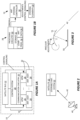
- FIGS 1A and 1B illustrate a satellite 10, according to one example embodiment, with the satellite 10 including a satellite bus 12 and a payload 14.
- the satellite bus 12 includes the electrical power system of the satellite 10, along with other spacecraft infrastructure, while the payload 14 comprises the communications equipment and associated antenna systems, for relaying signals between respective terrestrial stations, such as gateway terminals and user terminals.
- Example entities in the payload include communications circuitry 20 and one or more steerable antenna systems 22.
- Each steerable antenna system 22 comprises, for example, an antenna assembly 24 and a corresponding antenna positioning module (APM) 26 that is operative to steer the antenna assembly 24.
- APM antenna positioning module
- “Steering” encompasses a variety of techniques for changing the "pointing" direction of the antenna assembly 24, and each APM 26 comprises, for example, a motorized two-axis gimble or other steering element that performs commanded changes in the angular position of the antenna assembly 24 in two or more axes, e.g., to shift the geographic region on the surface of the Earth towards which the antenna assembly 24 is oriented.
- the communication circuitry 20 carries communication signals in the forward direction-towards user terminals-and in the return direction-from the user terminals-and may comprise a plurality of transponders that provide signal pathways through the satellite 10.
- Transponder functions include, for example, signal amplification, filtering, and frequency conversion, such as converting between frequencies used for uplink transmission and frequencies used for downlink transmission.
- a control system 28 performs a number of operations, including determining pointing errors with respect to any one or more of the steerable antenna systems 22. Pointing errors are reduced or eliminated by control circuitry comprised within the bus 12 translating the determined errors into corresponding steering adjustments and controlling the APM(s) 26 according to such adjustments, to perform antenna steering.
- Antenna steering may be understood as station keeping, wherein the satellite 10 compensates for changes in its attitude, to maintain a desired orientation of each antenna assembly 24.
- steering commands to an APM 26 provide for purposeful reorientation of the involved antenna assembly 24, e.g., to shift the terrestrial coverage area(s) provided by the antenna assembly 24.
- One or more embodiments of the satellite 10 use a phased-array antenna for one or more of the antenna systems 24, such that steering the antenna assembly 24 shifts the beams formed by the antenna assembly 24.
- Such shifts can be understood as shifting or otherwise moving the terrestrial beam footprints of the beams, which changes the terrestrial areas illuminated by the beams.
- An example control system 28 comprises processing circuitry 30 and associated storage 32.
- the processing circuitry 30 comprises dedicated, fixed circuitry or programmatically-configured circuitry, or a mix of dedicated circuitry and programmatically-configured circuitry.
- one or more microprocessors or other digital processors are specially adapted to carry out some or all of processing described herein for antenna steering, based on the execution of stored computer program instructions.
- the storage 32 comprises one or more types of computer-readable media, such as a mix of volatile memory for use in program execution-working memory-and nonvolatile memory for longer-term storage of one or more computer programs 34 containing the aforementioned computer program instructions.
- the storage 32 in one or more embodiments also stores satellite provisioning information or other types of configuration data, such as antenna data 36.
- Figure 1B depicts a particular example arrangement applicable to one or more embodiments, wherein control system 28 determines pointing errors, e.g., expressed in terms of azimuthal and elevational errors, and outputs corresponding error signaling to an antenna steering controller 38 comprised within the satellite bus 12.
- the antenna steering controller 38 comprises, for example, a programmed microprocessor, an Application Specific Integrated Circuit (ASIC), a Field Programmable Array (FPGA), or other digital processing circuit, along with supporting power and interface circuitry.
- ASIC Application Specific Integrated Circuit
- FPGA Field Programmable Array
- Processing performed by the antenna steering controller 38 includes translating the determined pointing errors for a steerable antenna system 22 into corresponding adjustments, e.g., steering commands, which are then applied to the steering element(s) 39 in the involved APM 26.
- the steerable antenna system 22 includes a reflector having azimuthal and elevational angles that are controlled by stepper motors in a two-axis gimble. Steering-angle adjustments in this context comprise changing the reflector angle by commanding determined numbers of motor steps, which correspond to, e.g., millidegrees of angular adjustment.
- FIG. 2 illustrates an example scenario of antenna steering, based on the satellite 10 receiving an uplink signal 42 from a terrestrial terminal 40, which also may be referred to as a ground station 40.
- the terrestrial terminal 40 comprises, for example, a satellite access node (SAN), which also may be referred to as a gateway terminal.
- SANs form part of the ground segment of a satellite communications system and interface directly or indirectly with external communication networks, such as the Internet or other Public Data Networks (PDNs), the Public Switched Telephone Network (PSTN), Public Land Mobile Networks (PLMNs), etc.
- PDNs Public Data Networks
- PSTN Public Switched Telephone Network
- PLMNs Public Land Mobile Networks
- the uplink signal 42 serves as a pointing reference for a steerable antenna system 22 onboard the satellite 10.
- the satellite 10 evaluates the current pointing direction of the steerable antenna system 22 by evaluating how the uplink reference signal impinges on the antenna assembly 24 included in the steerable antenna system 22.
- Figure 3 introduces example details that provide a context for such evaluations.
- An example antenna assembly 24 included in each steerable antenna system 22 comprises, for example, an antenna array 50 and an associated reflector 51.
- the uplink signal 42 impinges on the reflector 51, which reflects it onto the antenna array 50.
- the portion of the antenna array 50 that is illuminated by the uplink signal 42 depends on the orientation of the reflector 51 relative to the antenna array 50.
- the reflector 51 may be motorized or otherwise adjustable around one or more axes. Changing the orientation of the reflector 51 relative to the antenna array 50 effectively changes the pointing direction of the antenna array 50, and such changes therefore shift which portion of the antenna array 50 is illuminated by the uplink signal 42.
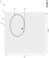
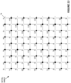
- FIG 4 offers an example illustration of such details by depicting the antenna array 50 in a plan view, i.e., looking directly at the face of the antenna array 50.
- the antenna array 50 comprises a plurality of array elements 52 arranged according to a feed grid 54, which can be understood as defining the geometric arrangement of individual array elements 52.
- the feed grid 54 defines regularly spaced column lines and row lines and each row-column intersection represents a grid position 56 in the feed grid 54.
- any particular grid position 56 in the feed grid 54 is defined by its X-Y coordinate, expressed as ⁇ x, y ⁇ .
- ⁇ x, y ⁇ represents a physical position or coordinate within the feed grid 54.
- the depicted embodiment of the antenna array 50 is based on a lattice arrangement of array elements 52 on the feed grid 54, where every other grid position 56 going row-wise or column-wise is occupied by an array element 52. In some embodiments, depending on involved signal frequencies and design requirements, all grid positions 56 are occupied by array elements 52, and it will be understood that the physical spacing of the grid positions 56 depends on the wavelengths of the signal frequencies of interest.
- Each array element 52 is a radiating or receiving element, or both, and has a corresponding transmit or receive signal chain associated with it.
- measurement circuitry onboard the satellite 10 is configured to measure received-signal power on each array element 52.
- the reference number "60" denotes the particular region-area-of the overall antenna array 50 that is illuminated by the uplink signal 42 for a current angular orientation of the reflector 51 relative to the antenna array 50-i.e., for a current pointing direction of the involved steerable antenna assembly 22.
- Illuminated in this context refers to which array elements 52 in the antenna array 50 register received-signal power levels above some minimum threshold, with respect to the uplink signal 42.
- the reference number "62" denotes a reference location that represents the nominal center of the illuminated region 60, if the steerable antenna system 22 was pointed correctly. That is, the current pointing error or alignment error of the steerable antenna system 22 is represented by the extent that the grid position 56 closest to the geometric center of the illuminated region 60 is not at the grid position 56 designated as the reference location 62.
- the reference location 62 is expressed in the X-Y coordinates of the feed grid 54.
- an "imaging” technique disclosed herein offers both accuracy and efficiency in determining the pointing error. Effectively, the technique forms an image corresponding to the antenna array 50, where pixels in the image correspond with array elements 52 in the antenna array 50 and are illuminated or not illuminated in dependence on the received-signal power registered on the corresponding array elements 52 during reception of the uplink signal 42.
- the image is or represents a power distribution profile for the antenna array.
- the image will contain an illuminated region corresponding to the array elements 52 that registered more than some minimum level of received-signal power during reception of the uplink signal 42.
- multiple power measurements may be made with respect to each array element 52 during a reception interval, and averaged or otherwise filtered, to obtain a final power measurement value that is used as an input to the image generating process.
- the pixel grid that defines the image has a defined correspondence with the feed grid 54, meaning that the reference location 62 can be projected into the pixel grid and the center of the illuminated region in the image that represents the uplink signal 42 can be compared to the projected reference location to compute a pointing error of the steerable antenna system 22 being evaluated.
- the image-processing technique can be performed independently, for each steerable antenna system 22 onboard the satellite 10.
- Figure 5 illustrates the foregoing example details by depicting an image 70 having an X' axis and a Y' axis and comprising a plurality of pixels 72 arranged on a pixel grid 74 that corresponds to the feed grid 54.
- "Corresponds to" in this context means that there is a defined mapping or correspondence between each grid position 76 in the pixel grid 74 and each grid position 56 in the feed grid 54.
- the image 70 may have the same resolution as the feed grid 54, meaning that there is one grid position 76 for each grid position 56 in the feed grid 54.
- the image 70 is a higher resolution or upscaled image, meaning that there are more grid positions 76 in the pixel grid 74 than there are grid positions 56 in the feed grid 54-e.g., there may be four grid positions 76 for every grid position 56.
- the numeric value of every pixel 72 in the image 70 depends on the received-signal power level registered on the corresponding array element(s) 52 in the antenna array 50 during the measurement interval used to obtain the image.
- the dependency may be a quantized relationship, e.g., a given pixel 72 may be considered as being “off” (not illuminated) or “on” (illuminated) as a function of whether the power level(s) registered for the corresponding array element(s) 52 satisfied some minimum threshold level.
- the image 70 may be referred to as a "power-distribution image" and as seen in Figure 5 , it contains an illuminated region 80 corresponding to the uplink signal 42.
- an illuminated pixel 72 has a numeric value resulting from the array element(s) 52 on which it depends having registered more than the minimum threshold level of received signal power during the interval in which the uplink signal 42 is received.
- the center of the illuminated region 80 which may be computed geometrically, e.g., as the centroid of the illuminated region 80 is represented by a triangle shape in the figure, shown as "82" in Figure 6 , and the reference location 62 as projected into the pixel grid 74 is represented by a star shape.
- the difference 84 between the center location 82 of the illuminated area 80 and the reference location 62 represents the current pointing error of the steerable antenna system 22.
- Figure 7 illustrates a method 700 of operation by the control system 28 of the satellite 10, consistent with the foregoing examples. Certain operations may be performed in an order other than suggested and the method 700 may be performed as part of ongoing satellite operations and repeated on a recurring basis, and may be carried out independently with respect to different steerable antenna systems 22 onboard the satellite 10.
- the method 700 includes receiving (Block 702) an uplink signal 42 that illuminates a particular region 60 of an antenna array 50 in dependence on a current pointing direction of a steerable antenna system 22 that includes the antenna array 50.
- the antenna array 50 comprises a plurality of array elements 52 arranged according to a feed grid 54.
- the method 700 includes converting (Block 704) received-signal power measurements made for individual array elements 52 of the antenna array 50 during reception of the uplink signal 42 into a power-distribution image 70 comprising pixels 72 arranged on a pixel grid 74 derived from the feed grid 54 and having pixel values determined in dependence on the received-signal power measurements made for corresponding ones of the array elements 52.
- each grid position 76 in the pixel grid 74 maps directly to one grid position 56 in the feed grid 54. If that grid position 56 is occupied, then the value of the pixel 72 depends on the received-signal power measurements made for the occupying array element 52. If the grid position 56 is unoccupied, then the value of the pixel 72 is calculated, at least initially, in dependence on the values of the adjacent pixels 72, corresponding to occupied grid positions 56 in the feed grid 54.
- any initially calculated pixel values may be revised, e.g., as a consequence of filtering, upscaling, and binarization, any or all of which may be performed in some embodiments of image generation.
- the method 700 continues with determining (Block 706) a center location 82 of an illuminated region 80 in the power-distribution image 70 that corresponds to the uplink signal 42, where the center location 82 is expressed in feed-grid coordinates. For example, the grid position 76 in the pixel grid 74 that is closest to the computed centroid of the illuminated region 80 is taken as the center location 82 and that location is then translated into feed-grid coordinates according to the mapping from the pixel grid 74 to the feed grid 54. From there, the method 700 continues with deriving (Block 708) a pointing correction for the steerable antenna system 22 in dependence on a difference 84 between the center location 82 and the reference location 62, which also is expressed in feed-grid coordinates.
- the uplink signal 42 originates, for example, from a ground station 40 that serves as a pointing reference for the steerable antenna system 22 and the reference location 62 corresponds with a correct pointing direction of the steerable antenna system 22.
- the steerable antenna system 22 may receive more than just the uplink signal 42 during the interval in which it makes received-signal power measurements for generation of the power-distribution image 70. Consequently, there may be multiple illuminated regions within the power-distribution image 70, with the locations of those regions being dependent on the respective angles-of-arrival of the signals.
- the method 700 includes identifying the illuminated region 80-i.e., the illuminated region corresponding to the uplink signal 42-from among two or more illuminated regions that are present in the power-distribution image 70, as a result of the steerable antenna system 22 receiving signal energy from more than one signal source while the received-signal power measurements are made.
- identifying the illuminated region 80 that corresponds with the uplink signal 42 comprises, for the two or more illuminated regions, comparing respective sizes of the two or more illuminated regions. This approach rests on the idea that the other signals are spurious and relatively weak, and therefore result in smaller illuminated regions in the power-distribution image 70.
- Converting the received-signal power measurements into the power-distribution image 70 comprises, for example, mapping the individual received-signal power measurements to a first set of pixels 72.
- Each pixel 72 in the first set of pixels 72 corresponds to a populated grid position 56 in the feed grid 54 and has a pixel value corresponding to the received-signal measurement made for the array element 52 at that populated grid position 56.
- converting the received-signal power measurements into the power-distribution image 70 further comprises creating an expanded, second set of pixels 72 encompassing the first set of pixels 72 and additional pixels 72 that correspond to unpopulated grid positions 56 in the feed grid 54.
- Each additional pixel 72 has a pixel value derived from one or more neighboring pixels in the first set of pixels 72.
- Converting the received-signal power measurements into the power-distribution image 70 further comprises, in at least one embodiment, creating an up-sampled image by generating multiple pixels 72 for each grid position 56 in the feed grid 54.
- the method 700 in at least one such embodiment includes filtering the up-sampled image, to obtain the power-distribution image 70 used for determining the center location 82 of the illuminated region 80 in the power distribution image 70 that corresponds to the uplink signal 42.
- forming the "final" power-distribution image 70 for evaluation includes binarizing the power-distribution image 70, and identifying, within the binarized power-distribution image 70, the illuminated region 80 that corresponds to the uplink signal 42.
- Figure 5 suggests binarization, where each pixel 72 either is off-white in the figure- or is on-black in the figure.
- the power distribution image 70 before binarization comprises pixels 72 having individual pixel values-numeric values-that are proportional to the received-signal power measured for the corresponding array elements 52, during an interval in which involved steerable antenna system 22 receives the uplink signal 42.
- individual pixels 72 have a "zero" value if the array element(s) 52 they correspond with have received-signal power measurements below a certain threshold.
- individual pixels 72 have a non-zero value that is proportional to the received-signal power levels measured on their corresponding array elements 52.
- Binarizing the power distribution image 70 means, with respect to each non-zero pixel 72 in the power distribution image 70, deciding whether to change the pixel value to zero (off) or to a maximum value (fully on) in dependence on whether the pixel value is above or below a defined binarization threshold.
- defined pixel values range from 0 to 100, with 0 corresponding to no received-signal power or received-signal power below some minimum power-level threshold, and 100 corresponding to received-signal power above some upper power-level threshold. Binarizing the power-distribution image 70 would then involve setting all pixels 72 having values below, say 20, to 0, and setting all pixels 72 having values above 20 to 100.
- Deriving the pointing correction for the steerable antenna system 22 in one or more embodiments of the method 700 comprises computing a horizontal offset in feed-grid coordinates between the center location 82 and the reference location 62 on a horizontal axis defined by the feed grid 54, computing a vertical offset in feed-grid coordinates between the center location 82 and the reference location 62 on a vertical axis defined by the feed grid 54, and translating the horizontal and vertical offsets into corresponding azimuthal and elevational pointing adjustments for the steerable antenna system 22.
- These azimuthal and elevational pointing adjustments are, for example, servo commands for changing the angle of the reflector 51 of the involved antenna assembly 24, which, as noted, effectively changes the pointing direction of the antenna array 50 included in the antenna assembly 24.
- the method 700 in one or more embodiments includes actuating a steering mechanism of the steerable antenna system 22, according to one or more actuator control signals determined as a function of the pointing correction.
- the method 700 in one or more further embodiments includes the satellite 10 performing downlink beamforming via a steerable antenna system 22, to provide a set of forward user beams 90 defining corresponding forward user beam coverage areas 92.
- the forward user beam coverage areas 92 are the terrestrial footprints of the respective forward user beams 90, and the pointing direction of the steerable antenna system 22 defines the geographical coordinates of an aggregate coverage area 94 defined by the set of forward user beams 90.
- the satellite 10 uses a steerable antenna system 22 to perform downlink beamforming along the lines suggested in Figure 8 , although the number of forward user beams 90 may be large, e.g., more than five hundred.
- forward refers to transmission toward user terminals served by the satellite 10, where such user terminals comprise set-top boxes or other data transceivers operating in respective ones of the beam coverage areas 94.
- FIG. 9 provides further example details for downlink beamforming, where transceiver circuitry 96 comprising signal chains on a per antenna element basis with respect to the antenna array 50 included in the involved steerable antenna system 22 provides power amplification of element signals 98.
- Each element signal 98 corresponds to one of the array elements 52 in the antenna array 50 and is the same as the other element signals 98 except for having element-specific weighting in terms of amplitude and phase, such that the transmitted versions 100 of the element signals 98 form the forward user beams 90 in the far field, as a result of the patterns of constructive and destructive interference formed by the radiating signals 100.
- the weighting may be performed onboard the satellite 10 or on the ground, using ground-based beamforming.
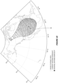
- Figure 10 illustrates a more detailed example of beamformed coverage using a steerable antenna system 22 of the satellite 10, where an aggregate coverage area 94 is formed by a plurality of beam coverage areas, depicted by the small squares in the diagram.
- the current boresight of the involved steerable antenna system 22 is shown, as indicated by the unfilled circle in the diagram.
- the filled circle indicates the nominal or intended boresight, and the method 700 provides the satellite 10 with an efficient and accurate mechanism for determining the pointing error.
- the satellite 10 may have multiple steerable antenna systems 22 onboard, and the satellite 10 may perform the method 700 with respect to each steerable antenna system 22, based on receiving a respective uplink signal 42 for each steerable antenna system 22. That is, each steerable antenna system 22 may provide service coverage in a different geographic region and there may be a ground station 40 in each geographic region that serves as the pointing reference for the respective steerable antenna system 22 onboard the satellite 10.
- control system 28 onboard the satellite 10 may repeat the method 700 on a recurring or triggered basis, with respect to each steerable antenna system 22-repeating the operations of receiving an uplink signal 42, which may be received on a recurring basis, converting the corresponding power measurements into a power-distribution image 70, determining the pointing error from the power-distribution image 70, and deriving pointing corrections based on the determined pointing error.
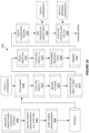
- Figure 11 details a method 1100 of generating a power-distribution image 70, and may be performed as part of the method 700.
- Image generation according to the method 1100 includes mapping (Block 1102) uplink power to feed coordinates and generating the initial image.
- Mapping means associating the received-signal power measured for each array element 52 for reception of an uplink signal 42 with the corresponding grid positions 56 in the feed grid 54.
- Generating the initial image comprises converting the measured powers into pixel values for the pixels 72 occupying respective grid positions 76 in a pixel grid 74 corresponding to the feed grid 54.
- the pixels 72 may be arranged in a matrix or other data structure, where the ordering or arrangement of the pixels 72 represents the pixel grid 74.
- the method 1100 continues with applying (Block 1104) filtering to pixels 72 in the initial image, e.g., a smoothing filter, upscaling/resizing (Block 1106) the image, applying (Block 1108) to the upscaled/resized image, and then binarizing (Block 1110) the image.
- the image as output from the binarizing operation is then used for identifying the illuminated region 80 of the pixel grid 74 that corresponds to the uplink signal 42, and then calculating (Block 1112) the center of the illuminated region 80, e.g., using a centroid formula.
- the center location 82 can then be expressed in feed-grid coordinates and compared with the reference location 62, which may also be expressed in feed-grid coordinates, to determine the pointing error of the involved steerable antenna system 22.
- Figure 12 illustrates a method 1200 performed by the satellite 10, with the method 1200 including choosing (Block 1202) a ground station 40 to use as a pointing reference for a steerable antenna system 22 onboard the satellite 10, and verifying (Block 1204) that all of one or more conditions for determining pointing corrections with respect to the pointing reference are fulfilled.
- Condition monitoring includes, for example, checking for one or more fault conditions that interfere with or prevent checking and correcting the pointing direction of the involved steerable antenna system 22, which also may be referred to as "antenna tracking.” Assuming the absence of fault conditions, the method 1200 continues with determining (Block 1206) the pointing error-e.g., according to the method 700-and applying (Block 1208) the pointing correction-e.g., commanding one or more servos of other positioning controls according to the determined pointing error.
- FIG. 13 illustrates a method 1300 performed by the satellite 10, with the illustrated processing representing an example approach to initialization.
- the processing may be performed as an initial part of the method 700 or performed in advance of performing the method 700 and it is based on example scenario involving three steerable antenna systems 22, each including a movable reflector R.
- R1 denotes the reflector in a first one of the steerable antenna systems
- R2 denotes the reflector in a second one of the steerable antenna systems
- R3 denotes the reflector in a third one of the steerable antenna systems 22.
- Each reflector R is associated with corresponding antenna array 50 having array elements 52 arranged on a feed grid 54 having X and Y dimensions.
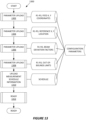
- the initialization method 1300 involves performing a series of uploading operations (Blocks 1302, 1304, 1306, and 1308), to upload a set of configuration parameters, including: (1) X, Y feed-grid coordinates for each reflector R1-R3; (2) the reference location 62 to be used for steering each one of the three steerable antenna systems 22, expressed in the corresponding feed-grid coordinates; (3) the beam deviations factors applicable to each steerable antenna system 22; (4) and the out-of-bounds limits applicable to each steerable antenna system 22.
- Uploading operations further include uploading (Block 1310) measurement schedule information that defines times for measuring uplink signal power for pointing-error determinations. Once the parameters and scheduling information are uploaded or otherwise configured on the satellite 10, it is ready to carry out antenna tracking (Block 1312).
- the antenna array 50 included in each steerable antenna system 22 has a defined number of rows and columns, e.g., 3 rows and 832 columns defining a 3 x 832 matrix of array elements 52.
- Each array element 52 may be associated with producing a forward user beam having a beam number and a feed-grid position defined by a Y position expressed in inches and an X position expressed in inches, with the position defining the location of the array element 52 / beam number within the involved feed grid 54.
- the reference location 62 for each steerable antenna system 22 may be expressed in X inches and Y inches.
- the beam deviation factors are, for example, a 2x2 matrix for each steerable antenna system 22, expressing a delta azimuthal value and a delta elevational value.
- a methodology disclosed herein finds the X, Y coordinate representing the illumination center of an uplink signal impinging on an antenna array 50 comprised in a steerable antenna system 22 of the satellite 10. The difference between that location and a reference location-e.g., a location that would attain if the steerable antenna system 22 was pointed correctly-gives delta x and delta y values.
- a reference location e.g., a location that would attain if the steerable antenna system 22 was pointed correctly-gives delta x and delta y values.
- coordinate moves in x and y translate into beam moves in millidegrees, and the beam deviation factors may be expressed in degrees per inch.
- the beam deviation factors allow the determined delta x and delta y values to be translated into angular adjustments for the reflector 51.
- Example limits include a lower limit on the signal level usable for antenna steering-i.e., a minimum signal level for the uplink signal 42 to be used as the pointing reference.
- the limits also may include an out-of-bounds error limit for each steerable antenna system 22 that prevents responding to a calculated pointing error if that error is too large according to defined error-size limit.
- Figure 14 illustrates a tracking method 1400 performed by the satellite 10 with respect to one of its steerable antenna systems 22, according to an example embodiment.
- the illustrated operations may be carried out by the control system 28 of the satellite payload 14, for example.
- Processing begins (Block 1402) with the satellite 10 in a READY state, such as depicted in Figure 13 . There may be conditions or times during which antenna tracking is not enabled and the satellite 10 thus checks whether tracking is enabled (Block 1404). If tracking is not enabled ("NO" from Block 1404), processing advances to Block 1406, in which corresponding tracking status information is sent to a telemetry (TLM) buffer, and a bus interface subprocess (Block 1408) may report the status information to the bus 12. In the case that tracking is disabled, for example, the interface subprocess may indicate that state to the bus 12.
- TLM telemetry
- Block 1410 may further include calculating an "uplink sum" by summing the per-element received signal power measurements used in computing the pointing error, to ensure that the measured uplink signal had sufficient power for use as a pointing reference.
- a power measurement subprocess runs according to the uploaded scheduling information-i.e., it performs uplink signal power measurements for the steerable antenna system 22 at scheduled times and stores those measurements in a memory that is read from, for carrying out the calculations in Block 1410.
- the computed pointing error (Az-El error) is sent to the TLM buffer (Block 1414), and the interface subprocess (Block 1408) sends a corresponding Az-El error request to the bus 12, with a corresponding antenna steering controller 38 of the bus 12 translating the Az-El error request into adjustments (control signaling) for revising the pointing direction of the steerable antenna system 22.
- Figure 15 illustrates an example "initial" image obtained in the process of generating a power-distribution image 70, where there is an initial set of pixels 72.
- Each pixel 72 corresponds to a grid position 56 in the feed grid 54 of the involved antenna assembly 24, and its pixel value is a digital value representing the received-signal power measured on the corresponding array element 52 in the antenna array 50.
- the pixels 72 corresponding to unoccupied/empty grid positions 56 have a zero value.
- the pixel values may be based on converting analog measurements of received-signal power on each array element 52 to a digital value using an 8-bit analog-to-digital (A/D) converter, for example.
- A/D analog-to-digital
- Figure 16 illustrates a detailed example according to one embodiment, for processing the initial image shown in Figure 15 , to obtain a final power-distribution image 70 that is used to evaluate the pointing error.
- Figure 16 illustrates particular filter types and filtering parameters, such details shall be understood as an example configuration. Other filter types or parameterizations may be used. Indeed, one or more embodiments include fewer filtering operations or omit filtering. Further, rather than implement the gray scaling and binarizing operations depicted in Figure 16 , one or more embodiments perform "color" image processing, such as where the different uplink power measurements made on a per-element basis are mapped into power ranges that correspond to different colors. Such an approach may be understood as generating a color "heat map" image, for analysis.
- the illustrated processing includes measuring (Block 1602) uplink (UL) power during a scheduled interval-e.g., during a quiescent interval during which the only signal purposefully received by the involved steerable antenna system 22 is an uplink signal 42 originating from a ground station 40 that serves as a pointing reference for the steerable antenna system 22.
- the steerable antenna system 22 may receive one or more spurious signals during this interval, which may be defined according to the corresponding playlist uploaded to the satellite 10, along with the other relevant configuration data.
- Processing continues with digitizing (Block 1604) the power measurements and storing them (Block 1606), for use in building an initial image (Block 1608), such as the one shown in Figure 15 .
- an initial image such as the one shown in Figure 15 .
- a series of processing operations to smooth the image and increase its resolution-i.e., upscaling is performed.
- upscaling creates a pixel grid 74 containing more pixels 72 than there are grid positions 56 in the feed grid 54
- there remains a defined mapping that translates grid positions 76 into the feed grid 56 and vice versa e.g., every grid position 56 in the feed grid 54 is represented by grid positions 76 in the (upscaled) pixel grid 74.
- a first operation applied to the basic or initial image from Figure 15 is a first filtering operation (Block 1610) applied to the pixels 72, using a filter "disk" having a radius of one.
- the disk filter is a two-dimensional (2D) filter exemplified by the below table: 0.08 0.46 0.08 0.46 1.00 0.46 0.08 0.46 0.08
- Figure 17 illustrates the effect of the filtering applied in Block 1610.
- Image filtering continues with the application of a median filter (Block 1612), e.g., a nine-point media filter as depicted below: i(x -1 ,y 1 ) i(x 0 ,y 1 ) i(x 1 ,y 1 ) i(x -1 ,y 0 ) i(x 0 ,y 0 ) i(x 1 ,y 0 ) i(x 1 ,y 0 ) i(x -1 ,y -1 ) i(x 0 ,y -1 ) i(x 1 ,y -1 )
- Figure 18 illustrates application of the median filter of Block 1612.
- Image processing continues with rescaling the pixel data (Block 1614), e.g., based on a minimum pixel value of 0 and a maximum pixel value of 255, resizing (Block 1616) the image, e.g., upscaling by a factor of four, and applying (Block 1618) a radius-4 disk filter to the upscaled image.
- An example disk (circular) filter appears below: 0.00 0.00 0.05 0.36 0.49 0.36 0.05 0.00 0.00 0.21 0.90 1.00 1.00 1.00 0.90 0.21 0.00 0.05 0.90 1.00 1.00 1.00 1.00.
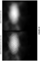
- Figure 19 illustrates the image after the processing of Blocks 1614, 1616, and 1618, with the resulting image then processed according to the processing of Block 1620, which involves a grayscale determination.
- the right-side image shown in Figure 19 illustrates the results of gray-scaling (Block 1620).
- Figure 20 illustrates the results of binarizing (Block 1622) the grayscale image.
- a notable aspect of Figure 20 is that it illustrates that there may be more than one illuminated region in the binarized image. This possibility is handled in the processing of Block 1624, which involves locating the illuminated regions within the binarized image, and finding the center (centroid) of the largest one among the illuminated regions (Block 1626). This logic can be understood as taking the largest one among the two or more illuminated regions in the binarized image as representing the uplink signal 42.
- the pointing correction according to Block 1628 comprises determining the delta Az (azimuthal) and delta El (elevational) adjustments for the reflector 51 of the subject steerable antenna system 22.
- the Az/El determination process represented by Figure 16 can be understood as: (1) receiving an uplink signal 42 during a "special time” when no other transmissions from the ground are present (in the involved frequency band); (2) using one or more radiofrequency (RF) power detectors to measure the received-signal power on individual array elements 52 of the antenna array 50, where the detection bandwidth may be narrowband or wideband, and continuous wave or modulated waveforms may be involved; and (3) the control system 28, which may include or comprise a "payload processor," collecting the power measurements and using an algorithm that converts the measurements into a power-distribution image 70, to determine the "uplink location" in feed-grid coordinates.
- RF radiofrequency
- X R and Y R are the coordinates of the reference locationg 62
- BDF beam deviation factors.
- the beam deviation factors are based on the reflector geometry.
- a satellite 10 comprises a steerable antenna system 22 that includes an antenna array 50 and is configured to receive an uplink signal 42 that illuminates a particular region of the antenna array 50 in dependence on a current pointing direction of the steerable antenna system 22.
- the antenna array 50 comprises a plurality of array elements 52 arranged according to a feed grid 54
- the satellite 10 further includes a control system 28 that is configured to convert received-signal power measurements made for individual array elements 52 of the antenna array 50 during reception of the uplink signal 42 into a power-distribution image 70 comprising pixels 72 arranged on a pixel grid 74.
- the pixel grid 74 is derived from the feed grid 54, e.g., either a one-to-one correspondence or an upscaled correspondence. In either case, the pixels 72 have pixel values determined in dependence on the received-signal power measurements made for corresponding ones of the array elements 52.
- the control system 28 is further configured to determine a center location 82 of an illuminated region 80 in the power-distribution image 70 that corresponds to the uplink signal 42. Still further, with the center location 82 expressed in feed-grid coordinates, the control system 28 is configured to derive a pointing correction for the steerable antenna system 22 in dependence on a difference 84 between the center location 82 and a reference location 62 that also is expressed in feed-grid coordinates.
- the control system 28 in one or more embodiments comprises processing circuitry 30, which may include or be associated with storage 32.
- the processing circuitry 30 comprises one or more microprocessors or other digital processors that is/are specially adapted to carry out the image-generation and pointing-correction determinations described herein-i.e., to convert received-signal power measurements into a power-distribution image 70 that represents the antenna array 50 and corresponding feed grid 54 within the antenna assembly 24 of a steerable antenna system 22, and to use that image to determine pointing corrections for the steerable antenna system 22.
- pointing corrections may comprise azimuthal and elevational adjustments to a reflector 51 that effectively controls the pointing direction of the involved antenna array 50.
- control system 28 in one or more embodiments is configured to perform any one or more of the operations detailed in any one or more of the methods 700, 1100, 1200, 1300, 1400, and 1600.
- the storage 32 stores one or more computer programs 34 comprising program instructions that, when executed by the one or more microprocessors or other digital processors comprising the processing circuitry 30, cause such processor(s) to perform the method operations.
- the control system 28 comprises processing circuitry 30 that is configured according to the execution of computer program instructions held in storage 32. However, whether implemented in fixed circuitry, programmatically-configured circuitry, or a mix of both, in one or more embodiments, the control system 28 is configured determine the center location 82 of the illuminated region 80 in the power-distribution image 70 by calculating the centroid of the illuminated region 80. As noted, the control system 28 may be configured to determine the center location 82 based on identifying the illuminated region 80 from among two or more illuminated regions that are present in the power-distribution image 70 as a result of the steerable antenna system 22 receiving signal energy from more than one signal source, while the received-signal power measurements are made. For example, the control system 28 is configured to identify the illuminated region 80 that corresponds with the uplink signal 42 by, for the two or more illuminated regions, comparing respective sizes of the two or more illuminated regions.
- control system 28 is configured to convert the received-signal power measurements into the power-distribution image 70 by mapping the individual received-signal power measurements to a first set of pixels 72, each pixel 72 in the first set of pixels 72 corresponding to a populated grid position 56 in the feed grid 54 and having a pixel value corresponding to the received-signal measurement made for the array element 52 at that populated grid position 56. Further, in at least one such embodiment, the control system 28 is configured to create an expanded, second set of pixels 72 encompassing the first set of pixels 72 and additional pixels 72 corresponding to unpopulated grid positions 56 in the feed grid 54, each additional pixel 72 having a pixel value derived from one or more neighboring pixels 72 in the first set of pixels 72.
- control system 28 is configured to create an up-sampled image by generating multiple pixels 72 for each grid position 56 in the feed grid 54.
- Creating new, additional pixels 72 comprises, for example, interpolating and extrapolating pixel values from the existing, neighboring pixels 72.
- control system 28 in one or more embodiments is configured to filter the up-sampled image, to obtain the power-distribution image 70 used for determining the center location 82 of the illuminated region 80 that corresponds to the uplink signal 42.
- processing may also include binarizing the up-sampled image, e.g., after smoothing and gray-scaling operations, to produce a distinct and relatively smooth on/off boundary defining the illuminated region 80.
- generating the power-distribution image 70 may comprise the following processing operations: (1) obtain received-signal power measurements for occupied grid positions 56 of the feed grid 54-i.e., grid positions 56 that have an array element 52; (2) create an initial image having one pixel grid position 76 for each feed grid position 56, where the pixels 72 at pixel grid positions 76 corresponding to occupied feed grid positions 56 have a digitized value corresponding to the power measurement made for that position and where pixels 72 at pixel grid positions 76 corresponding to unoccupied feed grid positions 56 have a zero value ("null" pixels); (3) use the non-zero pixel values to interpolate/extrapolate values for the null pixels 72; (4) perform initial smoothing (filtering) of the resulting intermediate image; (5) upscale the intermediate image to increase pixel resolution; (6) smooth the
- control system 28 is configured to derive pointing corrections for the steerable antenna system 22 on a recurring basis, based on recurring receptions of the uplink signal 42. See, for example, the slot playlist information uploaded to the satellite 10 as configuration information in Block 1310 of Figure 13 . That is, there may be special slots defined by a schedule, wherein the uplink signal 42 is the only uplink signal transmitted to the involved steerable antenna system 22 during the special slots, so that the uplink signal 42 is cleanly discernable in the generated power-distribution image 70.
- the control system 28 is configured to derive the pointing correction for the steerable antenna system 22 based on computing a horizontal offset in feed-grid coordinates between the center location 82 and the reference location 62 on a horizontal axis defined by the feed grid 54, computing a vertical offset in feed-grid coordinates between the center location 82 and the reference location 62 on a vertical axis defined by the feed grid 54, and translating the horizontal and vertical offsets into corresponding azimuthal and elevational pointing adjustments for the steerable antenna system 22. Further, the control system 28 is configured to actuate, or initiate actuation of, a steering mechanism of the steerable antenna system 22, according to one or more actuator control signals determined as a function of the pointing correction.
- the communication circuitry 20 of the satellite 10 performs downlink beamforming via the steerable antenna system 22, to provide a set of forward user beams 90 defining corresponding forward user beam coverage areas 92.
- the pointing direction of the steerable antenna system 22 defines the geographical coordinates of an aggregate coverage area 94 defined by the set of forward user beams 90.
Landscapes
- Engineering & Computer Science (AREA)
- Computer Networks & Wireless Communication (AREA)
- Signal Processing (AREA)
- Physics & Mathematics (AREA)
- Astronomy & Astrophysics (AREA)
- Aviation & Aerospace Engineering (AREA)
- General Physics & Mathematics (AREA)
- Radio Relay Systems (AREA)
- Variable-Direction Aerials And Aerial Arrays (AREA)
- Aerials With Secondary Devices (AREA)
Abstract
Description
- Systems and methods disclosed herein relate to pointing a steerable antenna system onboard a satellite.
- As demand for satellite communications continues to grow, the use of spot beams in satellite systems has become increasingly popular. A spot beam is a modulated satellite beam focused on a limited geographic region of the Earth. By reducing the coverage area of the beam, a more directional antenna may be used by the satellite to transmit the beam to Earth. This higher gain associated with a spot beam may produce better signal-to-noise (SNR) ratio at a user terminal, which allows for higher rates of data transfer between the satellite and terminal. Also, the smaller size of spot beams allows for frequency reuse with limited inter-beam interference, thereby providing for even greater increases in data throughput at a satellite.
- While spot beams can be very useful in areas of high demand, they may be susceptible to pointing errors. Satellite antenna movement within even a few thousandths of a degree may substantially change the coverage area of a spot beam on the Earth. Moreover, it is often the case that multiple spot beams are transmitted in a predetermined pattern from the satellite to various intended coverage areas. Thus, an antenna pointing error at the satellite may detrimentally reduce the quality of communications over multiple spot beams simultaneously.
- In the foregoing circumstances and in other scenarios, therefore, there is a need for determining the pointing error of a steerable antenna system, with
U.S. Pat. No. 8,723,724 B2 detailing techniques for pointing-orienting-a satellite antenna. Among the many challenges associated with maintaining a correct pointing direction for a satellite antenna are the complexities and durations associated with the procedure(s) used for determining pointing errors and the signaling needed for making such determinations. - Systems and methods disclosed herein for pointing a steerable antenna system onboard a satellite exploit advantageous image-processing techniques that provide a computationally-efficient and accurate way of determining the pointing error of the steerable antenna system and determining corresponding pointing corrections. Received-signal power measurements for individual array elements in an antenna array of the steerable antenna system provide the basis for forming a power-distribution image that reveals where an uplink signal falls on the array, which in turn provides a basis for determining the appropriate pointing correction.
- One embodiment comprises a method of operation by a control system of a satellite. The method includes: (a) receiving an uplink signal that illuminates a particular region of an antenna array in dependence on a current pointing direction of a steerable antenna system that includes the antenna array, and wherein the antenna array comprises a plurality of array elements arranged according to a feed grid; (b) converting received-signal power measurements made for individual array elements of the antenna array during reception of the uplink signal into a power-distribution image comprising pixels arranged on a pixel grid derived from the feed grid and having pixel values determined in dependence on the received-signal power measurements made for corresponding ones of the array elements; (c) determining a center location of an illuminated region in the power-distribution image that corresponds to the uplink signal, the center location expressed in feed-grid coordinates; and (d) deriving a pointing correction for the steerable antenna system in dependence on a difference between the center location and a reference location that also is expressed in feed-grid coordinates.
- Another embodiment comprises a satellite having a steerable antenna system and a control system. The steerable antenna system includes an antenna array and is configured to receive an uplink signal that illuminates a particular region of the antenna array in dependence on a current pointing direction of the steerable antenna system. The antenna array comprises a plurality of array elements arranged according to a feed grid. Correspondingly, the control system is configured to: (a) convert received-signal power measurements made for individual array elements of the antenna array during reception of the uplink signal into a power-distribution image comprising pixels arranged on a pixel grid derived from the feed grid and having pixel values determined in dependence on the received-signal power measurements made for corresponding ones of the array elements; (b) determine a center location of an illuminated region in the power-distribution image that corresponds to the uplink signal, the center location expressed in feed-grid coordinates; and (c) derive a pointing correction for the steerable antenna system in dependence on a difference between the center location and a reference location that also is expressed in feed-grid coordinates.
- Of course, the present invention is not limited to the above features and advantages. Indeed, those skilled in the art will recognize additional features and advantages upon reading the following detailed description, and upon viewing the accompanying drawings.
-
-
Figures 1A and 1B are block diagrams of a satellite configured for operation in a satellite communications system, according to one embodiment. -
Figure 2 is a block diagram of a terrestrial ground station configured for operation in a satellite communications system, according to one embodiment. -
Figure 3 is a block diagram of an antenna assembly of a steerable antenna system, according to one embodiment. -
Figure 4 is a block diagram of an antenna array and its associated feed grid, such as may be included in the antenna assembly ofFigure 3 , according to one embodiment. -
Figure 5 is a diagram of a power-distribution image, as generated for pointing-error determinations according to one embodiment. -
Figure 6 is a diagram of a center of an illuminated region within a power-distribution image in relative position to a nominal or desired center, according to one embodiment. -
Figure 7 is a logic flow diagram of a method of operation for determining a power-distribution image, according to one embodiment. -
Figure 8 is a diagram illustrating an example set of forward user beams, as produced by an example steerable antenna system, according to one embodiment. -
Figure 9 is a block diagram of antenna-assembly details of an antenna assembly of a steerable antenna system forward beamforming, according to one embodiment. -
Figure 10 is a diagram illustrating example beam coverage areas-spot beam areas- and a corresponding aggregate coverage area for forward beamforming, according to one embodiment. -
Figure 11 is a logic flow diagram of example details for the method ofFigure 7 . -
Figure 12 is a logic flow diagram of an overall method of operation for steering a steerable antenna system, according to one embodiment. -
Figure 13 is a logic flow diagram of a method of obtaining configuration parameters, for use in performing antenna steering, according to one embodiment. -
Figure 14 is a logic flow diagram illustrating example details for carrying out the method ofFigure 12 . -
Figure 15 is a diagram of an example initial image for further processing to obtain a power-distribution image, according to one embodiment. -
Figure 16 is a logic flow diagram of example details of obtaining an initial image of the sort illustrated inFigure 15 and example details for further processing, according to one embodiment. -
Figures 17-20 are image plots illustrating example effects of the image-processing steps detailed inFigure 16 . -
Figures 1A and 1B illustrate asatellite 10, according to one example embodiment, with thesatellite 10 including asatellite bus 12 and apayload 14. Thesatellite bus 12 includes the electrical power system of thesatellite 10, along with other spacecraft infrastructure, while thepayload 14 comprises the communications equipment and associated antenna systems, for relaying signals between respective terrestrial stations, such as gateway terminals and user terminals. - Example entities in the payload include
communications circuitry 20 and one or moresteerable antenna systems 22. Eachsteerable antenna system 22 comprises, for example, anantenna assembly 24 and a corresponding antenna positioning module (APM) 26 that is operative to steer theantenna assembly 24. "Steering" encompasses a variety of techniques for changing the "pointing" direction of theantenna assembly 24, and eachAPM 26 comprises, for example, a motorized two-axis gimble or other steering element that performs commanded changes in the angular position of theantenna assembly 24 in two or more axes, e.g., to shift the geographic region on the surface of the Earth towards which theantenna assembly 24 is oriented. - The
communication circuitry 20 carries communication signals in the forward direction-towards user terminals-and in the return direction-from the user terminals-and may comprise a plurality of transponders that provide signal pathways through thesatellite 10. Transponder functions include, for example, signal amplification, filtering, and frequency conversion, such as converting between frequencies used for uplink transmission and frequencies used for downlink transmission. - A
control system 28 performs a number of operations, including determining pointing errors with respect to any one or more of thesteerable antenna systems 22. Pointing errors are reduced or eliminated by control circuitry comprised within thebus 12 translating the determined errors into corresponding steering adjustments and controlling the APM(s) 26 according to such adjustments, to perform antenna steering. Antenna steering may be understood as station keeping, wherein thesatellite 10 compensates for changes in its attitude, to maintain a desired orientation of eachantenna assembly 24. In other embodiments or scenarios, steering commands to anAPM 26 provide for purposeful reorientation of theinvolved antenna assembly 24, e.g., to shift the terrestrial coverage area(s) provided by theantenna assembly 24. One or more embodiments of thesatellite 10 use a phased-array antenna for one or more of theantenna systems 24, such that steering theantenna assembly 24 shifts the beams formed by theantenna assembly 24. Such shifts can be understood as shifting or otherwise moving the terrestrial beam footprints of the beams, which changes the terrestrial areas illuminated by the beams. - An
example control system 28 comprisesprocessing circuitry 30 and associatedstorage 32. Theprocessing circuitry 30 comprises dedicated, fixed circuitry or programmatically-configured circuitry, or a mix of dedicated circuitry and programmatically-configured circuitry. For example, one or more microprocessors or other digital processors are specially adapted to carry out some or all of processing described herein for antenna steering, based on the execution of stored computer program instructions. - Correspondingly, in one or more embodiments, the
storage 32 comprises one or more types of computer-readable media, such as a mix of volatile memory for use in program execution-working memory-and nonvolatile memory for longer-term storage of one ormore computer programs 34 containing the aforementioned computer program instructions. Thestorage 32 in one or more embodiments also stores satellite provisioning information or other types of configuration data, such asantenna data 36. -
Figure 1B depicts a particular example arrangement applicable to one or more embodiments, whereincontrol system 28 determines pointing errors, e.g., expressed in terms of azimuthal and elevational errors, and outputs corresponding error signaling to anantenna steering controller 38 comprised within thesatellite bus 12. Theantenna steering controller 38 comprises, for example, a programmed microprocessor, an Application Specific Integrated Circuit (ASIC), a Field Programmable Array (FPGA), or other digital processing circuit, along with supporting power and interface circuitry. - Processing performed by the
antenna steering controller 38 includes translating the determined pointing errors for asteerable antenna system 22 into corresponding adjustments, e.g., steering commands, which are then applied to the steering element(s) 39 in theinvolved APM 26. As a non-limiting example, thesteerable antenna system 22 includes a reflector having azimuthal and elevational angles that are controlled by stepper motors in a two-axis gimble. Steering-angle adjustments in this context comprise changing the reflector angle by commanding determined numbers of motor steps, which correspond to, e.g., millidegrees of angular adjustment. -
Figure 2 illustrates an example scenario of antenna steering, based on thesatellite 10 receiving anuplink signal 42 from aterrestrial terminal 40, which also may be referred to as aground station 40. Theterrestrial terminal 40 comprises, for example, a satellite access node (SAN), which also may be referred to as a gateway terminal. SANs form part of the ground segment of a satellite communications system and interface directly or indirectly with external communication networks, such as the Internet or other Public Data Networks (PDNs), the Public Switched Telephone Network (PSTN), Public Land Mobile Networks (PLMNs), etc. - In at least one embodiment, the
uplink signal 42 serves as a pointing reference for asteerable antenna system 22 onboard thesatellite 10. Particularly, thesatellite 10 evaluates the current pointing direction of thesteerable antenna system 22 by evaluating how the uplink reference signal impinges on theantenna assembly 24 included in thesteerable antenna system 22.Figure 3 introduces example details that provide a context for such evaluations. - An
example antenna assembly 24 included in eachsteerable antenna system 22 comprises, for example, anantenna array 50 and an associatedreflector 51. As seen inFigure 3 , theuplink signal 42 impinges on thereflector 51, which reflects it onto theantenna array 50. As such, the portion of theantenna array 50 that is illuminated by theuplink signal 42 depends on the orientation of thereflector 51 relative to theantenna array 50. As suggested inFigure 3 , thereflector 51 may be motorized or otherwise adjustable around one or more axes. Changing the orientation of thereflector 51 relative to theantenna array 50 effectively changes the pointing direction of theantenna array 50, and such changes therefore shift which portion of theantenna array 50 is illuminated by theuplink signal 42. -
Figure 4 offers an example illustration of such details by depicting theantenna array 50 in a plan view, i.e., looking directly at the face of theantenna array 50. As illustrated, theantenna array 50 comprises a plurality ofarray elements 52 arranged according to afeed grid 54, which can be understood as defining the geometric arrangement ofindividual array elements 52. As depicted, thefeed grid 54 defines regularly spaced column lines and row lines and each row-column intersection represents agrid position 56 in thefeed grid 54. - If the horizontal distance spanned by the plurality of feed-grid columns depicted in
Figure 4 is taken as the X axis and the vertical distance spanned by the plurality of feed-grid rows is taken as the Y axis, anyparticular grid position 56 in thefeed grid 54 is defined by its X-Y coordinate, expressed as {x, y}. Here, {x, y} represents a physical position or coordinate within thefeed grid 54. - The depicted embodiment of the
antenna array 50 is based on a lattice arrangement ofarray elements 52 on thefeed grid 54, where everyother grid position 56 going row-wise or column-wise is occupied by anarray element 52. In some embodiments, depending on involved signal frequencies and design requirements, allgrid positions 56 are occupied byarray elements 52, and it will be understood that the physical spacing of the grid positions 56 depends on the wavelengths of the signal frequencies of interest. - Each
array element 52 is a radiating or receiving element, or both, and has a corresponding transmit or receive signal chain associated with it. In one or more embodiments, measurement circuitry onboard thesatellite 10 is configured to measure received-signal power on eacharray element 52. InFigure 4 , the reference number "60" denotes the particular region-area-of theoverall antenna array 50 that is illuminated by theuplink signal 42 for a current angular orientation of thereflector 51 relative to the antenna array 50-i.e., for a current pointing direction of the involvedsteerable antenna assembly 22. "Illuminated" in this context refers to whicharray elements 52 in theantenna array 50 register received-signal power levels above some minimum threshold, with respect to theuplink signal 42. - The reference number "62" denotes a reference location that represents the nominal center of the illuminated
region 60, if thesteerable antenna system 22 was pointed correctly. That is, the current pointing error or alignment error of thesteerable antenna system 22 is represented by the extent that thegrid position 56 closest to the geometric center of the illuminatedregion 60 is not at thegrid position 56 designated as thereference location 62. Thereference location 62 is expressed in the X-Y coordinates of thefeed grid 54. - An "imaging" technique disclosed herein offers both accuracy and efficiency in determining the pointing error. Effectively, the technique forms an image corresponding to the
antenna array 50, where pixels in the image correspond witharray elements 52 in theantenna array 50 and are illuminated or not illuminated in dependence on the received-signal power registered on thecorresponding array elements 52 during reception of theuplink signal 42. The image is or represents a power distribution profile for the antenna array. - As such, the image will contain an illuminated region corresponding to the
array elements 52 that registered more than some minimum level of received-signal power during reception of theuplink signal 42. In this regard, multiple power measurements may be made with respect to eacharray element 52 during a reception interval, and averaged or otherwise filtered, to obtain a final power measurement value that is used as an input to the image generating process. - The pixel grid that defines the image has a defined correspondence with the
feed grid 54, meaning that thereference location 62 can be projected into the pixel grid and the center of the illuminated region in the image that represents theuplink signal 42 can be compared to the projected reference location to compute a pointing error of thesteerable antenna system 22 being evaluated. The image-processing technique can be performed independently, for eachsteerable antenna system 22 onboard thesatellite 10. -
Figure 5 illustrates the foregoing example details by depicting animage 70 having an X' axis and a Y' axis and comprising a plurality ofpixels 72 arranged on apixel grid 74 that corresponds to thefeed grid 54. "Corresponds to" in this context means that there is a defined mapping or correspondence between eachgrid position 76 in thepixel grid 74 and eachgrid position 56 in thefeed grid 54. For example, theimage 70 may have the same resolution as thefeed grid 54, meaning that there is onegrid position 76 for eachgrid position 56 in thefeed grid 54. In at least one embodiment, theimage 70 is a higher resolution or upscaled image, meaning that there aremore grid positions 76 in thepixel grid 74 than there aregrid positions 56 in the feed grid 54-e.g., there may be fourgrid positions 76 for everygrid position 56. However, even with upscaling, there remains a defined mapping or correspondence betweengrid positions 76 in thepixel grid 74 andgrid positions 56 in thefeed grid 54. As such, the numeric value of everypixel 72 in theimage 70 depends on the received-signal power level registered on the corresponding array element(s) 52 in theantenna array 50 during the measurement interval used to obtain the image. The dependency may be a quantized relationship, e.g., a givenpixel 72 may be considered as being "off" (not illuminated) or "on" (illuminated) as a function of whether the power level(s) registered for the corresponding array element(s) 52 satisfied some minimum threshold level. - Thus, the
image 70 may be referred to as a "power-distribution image" and as seen inFigure 5 , it contains an illuminatedregion 80 corresponding to theuplink signal 42. Note that in this context, anilluminated pixel 72 has a numeric value resulting from the array element(s) 52 on which it depends having registered more than the minimum threshold level of received signal power during the interval in which theuplink signal 42 is received. The center of the illuminatedregion 80, which may be computed geometrically, e.g., as the centroid of the illuminatedregion 80 is represented by a triangle shape in the figure, shown as "82" inFigure 6 , and thereference location 62 as projected into thepixel grid 74 is represented by a star shape. Thedifference 84 between thecenter location 82 of the illuminatedarea 80 and thereference location 62 represents the current pointing error of thesteerable antenna system 22. -
Figure 7 illustrates amethod 700 of operation by thecontrol system 28 of thesatellite 10, consistent with the foregoing examples. Certain operations may be performed in an order other than suggested and themethod 700 may be performed as part of ongoing satellite operations and repeated on a recurring basis, and may be carried out independently with respect to differentsteerable antenna systems 22 onboard thesatellite 10. - The
method 700 includes receiving (Block 702) anuplink signal 42 that illuminates aparticular region 60 of anantenna array 50 in dependence on a current pointing direction of asteerable antenna system 22 that includes theantenna array 50. Theantenna array 50 comprises a plurality ofarray elements 52 arranged according to afeed grid 54. Further, themethod 700 includes converting (Block 704) received-signal power measurements made forindividual array elements 52 of theantenna array 50 during reception of theuplink signal 42 into a power-distribution image 70 comprisingpixels 72 arranged on apixel grid 74 derived from thefeed grid 54 and having pixel values determined in dependence on the received-signal power measurements made for corresponding ones of thearray elements 52. - For example, with no upscaling or before performing upscaling, there is a one-to-one correspondence between the
feed grid 54 and thepixel grid 74, meaning that eachgrid position 76 in thepixel grid 74 maps directly to onegrid position 56 in thefeed grid 54. If thatgrid position 56 is occupied, then the value of thepixel 72 depends on the received-signal power measurements made for the occupyingarray element 52. If thegrid position 56 is unoccupied, then the value of thepixel 72 is calculated, at least initially, in dependence on the values of theadjacent pixels 72, corresponding to occupied grid positions 56 in thefeed grid 54. Of course, any initially calculated pixel values may be revised, e.g., as a consequence of filtering, upscaling, and binarization, any or all of which may be performed in some embodiments of image generation. - However the pixel values are finalized, the
method 700 continues with determining (Block 706) acenter location 82 of an illuminatedregion 80 in the power-distribution image 70 that corresponds to theuplink signal 42, where thecenter location 82 is expressed in feed-grid coordinates. For example, thegrid position 76 in thepixel grid 74 that is closest to the computed centroid of the illuminatedregion 80 is taken as thecenter location 82 and that location is then translated into feed-grid coordinates according to the mapping from thepixel grid 74 to thefeed grid 54. From there, themethod 700 continues with deriving (Block 708) a pointing correction for thesteerable antenna system 22 in dependence on adifference 84 between thecenter location 82 and thereference location 62, which also is expressed in feed-grid coordinates. - The
uplink signal 42 originates, for example, from aground station 40 that serves as a pointing reference for thesteerable antenna system 22 and thereference location 62 corresponds with a correct pointing direction of thesteerable antenna system 22. - As noted earlier, the
steerable antenna system 22 may receive more than just theuplink signal 42 during the interval in which it makes received-signal power measurements for generation of the power-distribution image 70. Consequently, there may be multiple illuminated regions within the power-distribution image 70, with the locations of those regions being dependent on the respective angles-of-arrival of the signals. Thus, in at least one embodiment, themethod 700 includes identifying the illuminated region 80-i.e., the illuminated region corresponding to the uplink signal 42-from among two or more illuminated regions that are present in the power-distribution image 70, as a result of thesteerable antenna system 22 receiving signal energy from more than one signal source while the received-signal power measurements are made. - In at least one embodiment, identifying the illuminated
region 80 that corresponds with theuplink signal 42 comprises, for the two or more illuminated regions, comparing respective sizes of the two or more illuminated regions. This approach rests on the idea that the other signals are spurious and relatively weak, and therefore result in smaller illuminated regions in the power-distribution image 70. - Converting the received-signal power measurements into the power-
distribution image 70 comprises, for example, mapping the individual received-signal power measurements to a first set ofpixels 72. Eachpixel 72 in the first set ofpixels 72 corresponds to apopulated grid position 56 in thefeed grid 54 and has a pixel value corresponding to the received-signal measurement made for thearray element 52 at thatpopulated grid position 56. Continuing this example, converting the received-signal power measurements into the power-distribution image 70 further comprises creating an expanded, second set ofpixels 72 encompassing the first set ofpixels 72 andadditional pixels 72 that correspond to unpopulated grid positions 56 in thefeed grid 54. Eachadditional pixel 72 has a pixel value derived from one or more neighboring pixels in the first set ofpixels 72. - Converting the received-signal power measurements into the power-
distribution image 70 further comprises, in at least one embodiment, creating an up-sampled image by generatingmultiple pixels 72 for eachgrid position 56 in thefeed grid 54. Themethod 700 in at least one such embodiment includes filtering the up-sampled image, to obtain the power-distribution image 70 used for determining thecenter location 82 of the illuminatedregion 80 in thepower distribution image 70 that corresponds to theuplink signal 42. - Further, in one or more embodiments, forming the "final" power-
distribution image 70 for evaluation includes binarizing the power-distribution image 70, and identifying, within the binarized power-distribution image 70, the illuminatedregion 80 that corresponds to theuplink signal 42.Figure 5 suggests binarization, where eachpixel 72 either is off-white in the figure- or is on-black in the figure. - In at least one embodiment of the
method 700, thepower distribution image 70 before binarization comprisespixels 72 having individual pixel values-numeric values-that are proportional to the received-signal power measured for thecorresponding array elements 52, during an interval in which involvedsteerable antenna system 22 receives theuplink signal 42. For example,individual pixels 72 have a "zero" value if the array element(s) 52 they correspond with have received-signal power measurements below a certain threshold. However,individual pixels 72 have a non-zero value that is proportional to the received-signal power levels measured on theircorresponding array elements 52. - Binarizing the
power distribution image 70 means, with respect to eachnon-zero pixel 72 in thepower distribution image 70, deciding whether to change the pixel value to zero (off) or to a maximum value (fully on) in dependence on whether the pixel value is above or below a defined binarization threshold. Merely as a non-limiting example, consider an approach where defined pixel values range from 0 to 100, with 0 corresponding to no received-signal power or received-signal power below some minimum power-level threshold, and 100 corresponding to received-signal power above some upper power-level threshold. Binarizing the power-distribution image 70 would then involve setting allpixels 72 having values below, say 20, to 0, and setting allpixels 72 having values above 20 to 100. - Deriving the pointing correction for the
steerable antenna system 22 in one or more embodiments of themethod 700 comprises computing a horizontal offset in feed-grid coordinates between thecenter location 82 and thereference location 62 on a horizontal axis defined by thefeed grid 54, computing a vertical offset in feed-grid coordinates between thecenter location 82 and thereference location 62 on a vertical axis defined by thefeed grid 54, and translating the horizontal and vertical offsets into corresponding azimuthal and elevational pointing adjustments for thesteerable antenna system 22. These azimuthal and elevational pointing adjustments are, for example, servo commands for changing the angle of thereflector 51 of the involvedantenna assembly 24, which, as noted, effectively changes the pointing direction of theantenna array 50 included in theantenna assembly 24. Thus, themethod 700 in one or more embodiments includes actuating a steering mechanism of thesteerable antenna system 22, according to one or more actuator control signals determined as a function of the pointing correction. - As shown in
Figure 8 , themethod 700 in one or more further embodiments includes thesatellite 10 performing downlink beamforming via asteerable antenna system 22, to provide a set of forward user beams 90 defining corresponding forward userbeam coverage areas 92. The forward userbeam coverage areas 92 are the terrestrial footprints of the respective forward user beams 90, and the pointing direction of thesteerable antenna system 22 defines the geographical coordinates of anaggregate coverage area 94 defined by the set of forward user beams 90. - In example operation, the
satellite 10 uses asteerable antenna system 22 to perform downlink beamforming along the lines suggested inFigure 8 , although the number of forward user beams 90 may be large, e.g., more than five hundred. Here, "forward" refers to transmission toward user terminals served by thesatellite 10, where such user terminals comprise set-top boxes or other data transceivers operating in respective ones of thebeam coverage areas 94. -
Figure 9 provides further example details for downlink beamforming, wheretransceiver circuitry 96 comprising signal chains on a per antenna element basis with respect to theantenna array 50 included in the involvedsteerable antenna system 22 provides power amplification of element signals 98. Eachelement signal 98 corresponds to one of thearray elements 52 in theantenna array 50 and is the same as the other element signals 98 except for having element-specific weighting in terms of amplitude and phase, such that the transmittedversions 100 of the element signals 98 form the forward user beams 90 in the far field, as a result of the patterns of constructive and destructive interference formed by the radiating signals 100. The weighting may be performed onboard thesatellite 10 or on the ground, using ground-based beamforming. -
Figure 10 illustrates a more detailed example of beamformed coverage using asteerable antenna system 22 of thesatellite 10, where anaggregate coverage area 94 is formed by a plurality of beam coverage areas, depicted by the small squares in the diagram. The current boresight of the involvedsteerable antenna system 22 is shown, as indicated by the unfilled circle in the diagram. The filled circle indicates the nominal or intended boresight, and themethod 700 provides thesatellite 10 with an efficient and accurate mechanism for determining the pointing error. - As noted, the
satellite 10 may have multiplesteerable antenna systems 22 onboard, and thesatellite 10 may perform themethod 700 with respect to eachsteerable antenna system 22, based on receiving arespective uplink signal 42 for eachsteerable antenna system 22. That is, eachsteerable antenna system 22 may provide service coverage in a different geographic region and there may be aground station 40 in each geographic region that serves as the pointing reference for the respectivesteerable antenna system 22 onboard thesatellite 10. A further point regarding themethod 700 is that thecontrol system 28 onboard thesatellite 10 may repeat themethod 700 on a recurring or triggered basis, with respect to each steerable antenna system 22-repeating the operations of receiving anuplink signal 42, which may be received on a recurring basis, converting the corresponding power measurements into a power-distribution image 70, determining the pointing error from the power-distribution image 70, and deriving pointing corrections based on the determined pointing error. -
Figure 11 details amethod 1100 of generating a power-distribution image 70, and may be performed as part of themethod 700. Image generation according to themethod 1100 includes mapping (Block 1102) uplink power to feed coordinates and generating the initial image. "Mapping" means associating the received-signal power measured for eacharray element 52 for reception of anuplink signal 42 with the corresponding grid positions 56 in thefeed grid 54. Generating the initial image comprises converting the measured powers into pixel values for thepixels 72 occupying respective grid positions 76 in apixel grid 74 corresponding to thefeed grid 54. Thepixels 72 may be arranged in a matrix or other data structure, where the ordering or arrangement of thepixels 72 represents thepixel grid 74. - The
method 1100 continues with applying (Block 1104) filtering topixels 72 in the initial image, e.g., a smoothing filter, upscaling/resizing (Block 1106) the image, applying (Block 1108) to the upscaled/resized image, and then binarizing (Block 1110) the image. The image as output from the binarizing operation is then used for identifying the illuminatedregion 80 of thepixel grid 74 that corresponds to theuplink signal 42, and then calculating (Block 1112) the center of the illuminatedregion 80, e.g., using a centroid formula. Thecenter location 82 can then be expressed in feed-grid coordinates and compared with thereference location 62, which may also be expressed in feed-grid coordinates, to determine the pointing error of the involvedsteerable antenna system 22. -
Figure 12 illustrates amethod 1200 performed by thesatellite 10, with themethod 1200 including choosing (Block 1202) aground station 40 to use as a pointing reference for asteerable antenna system 22 onboard thesatellite 10, and verifying (Block 1204) that all of one or more conditions for determining pointing corrections with respect to the pointing reference are fulfilled. Condition monitoring includes, for example, checking for one or more fault conditions that interfere with or prevent checking and correcting the pointing direction of the involvedsteerable antenna system 22, which also may be referred to as "antenna tracking." Assuming the absence of fault conditions, themethod 1200 continues with determining (Block 1206) the pointing error-e.g., according to the method 700-and applying (Block 1208) the pointing correction-e.g., commanding one or more servos of other positioning controls according to the determined pointing error. -
Figure 13 illustrates amethod 1300 performed by thesatellite 10, with the illustrated processing representing an example approach to initialization. The processing may be performed as an initial part of themethod 700 or performed in advance of performing themethod 700 and it is based on example scenario involving threesteerable antenna systems 22, each including a movable reflector R. Hence, "R1" denotes the reflector in a first one of thesteerable antenna systems 22, "R2" denotes the reflector in a second one of thesteerable antenna systems 22, and "R3" denotes the reflector in a third one of thesteerable antenna systems 22. Each reflector R is associated withcorresponding antenna array 50 havingarray elements 52 arranged on afeed grid 54 having X and Y dimensions. - The
initialization method 1300 involves performing a series of uploading operations (Blocks reference location 62 to be used for steering each one of the threesteerable antenna systems 22, expressed in the corresponding feed-grid coordinates; (3) the beam deviations factors applicable to eachsteerable antenna system 22; (4) and the out-of-bounds limits applicable to eachsteerable antenna system 22. Uploading operations further include uploading (Block 1310) measurement schedule information that defines times for measuring uplink signal power for pointing-error determinations. Once the parameters and scheduling information are uploaded or otherwise configured on thesatellite 10, it is ready to carry out antenna tracking (Block 1312). - In an example embodiment, the
antenna array 50 included in eachsteerable antenna system 22 has a defined number of rows and columns, e.g., 3 rows and 832 columns defining a 3 x 832 matrix ofarray elements 52. Eacharray element 52 may be associated with producing a forward user beam having a beam number and a feed-grid position defined by a Y position expressed in inches and an X position expressed in inches, with the position defining the location of thearray element 52 / beam number within theinvolved feed grid 54. Similarly, thereference location 62 for eachsteerable antenna system 22 may be expressed in X inches and Y inches. - The beam deviation factors are, for example, a 2x2 matrix for each
steerable antenna system 22, expressing a delta azimuthal value and a delta elevational value. As a more detailed example, a methodology disclosed herein, such as in the embodiment shown inFigure 7 , finds the X, Y coordinate representing the illumination center of an uplink signal impinging on anantenna array 50 comprised in asteerable antenna system 22 of thesatellite 10. The difference between that location and a reference location-e.g., a location that would attain if thesteerable antenna system 22 was pointed correctly-gives delta x and delta y values. With offset fed reflectors, coordinate moves in x and y translate into beam moves in millidegrees, and the beam deviation factors may be expressed in degrees per inch. As such, the beam deviation factors allow the determined delta x and delta y values to be translated into angular adjustments for thereflector 51. - As for the applicable limits, they too may be expressed per
steerable antenna system 22. Example limits include a lower limit on the signal level usable for antenna steering-i.e., a minimum signal level for theuplink signal 42 to be used as the pointing reference. The limits also may include an out-of-bounds error limit for eachsteerable antenna system 22 that prevents responding to a calculated pointing error if that error is too large according to defined error-size limit. -
Figure 14 illustrates atracking method 1400 performed by thesatellite 10 with respect to one of itssteerable antenna systems 22, according to an example embodiment. The illustrated operations may be carried out by thecontrol system 28 of thesatellite payload 14, for example. - Processing begins (Block 1402) with the
satellite 10 in a READY state, such as depicted inFigure 13 . There may be conditions or times during which antenna tracking is not enabled and thesatellite 10 thus checks whether tracking is enabled (Block 1404). If tracking is not enabled ("NO" from Block 1404), processing advances toBlock 1406, in which corresponding tracking status information is sent to a telemetry (TLM) buffer, and a bus interface subprocess (Block 1408) may report the status information to thebus 12. In the case that tracking is disabled, for example, the interface subprocess may indicate that state to thebus 12. - On the other hand, if tracking is enabled ("YES" from Block 1404) and uplink (UL) power measurements for a received uplink signal are available for the
steerable antenna system 22, themethod 1400 continues with calculating the pointing error (Block 1410). The pointing error is expressed as an azimuthal error (Az) and an elevational error (El) for the angular settings of thereflector 51 included in the involvedsteerable antenna system 22, and the computation of the pointing error relies on the image-generation method 700, using the configuration data detailed inFigure 13 . Block 1410 may further include calculating an "uplink sum" by summing the per-element received signal power measurements used in computing the pointing error, to ensure that the measured uplink signal had sufficient power for use as a pointing reference. Here, note that a power measurement subprocess (Block 1416) runs according to the uploaded scheduling information-i.e., it performs uplink signal power measurements for thesteerable antenna system 22 at scheduled times and stores those measurements in a memory that is read from, for carrying out the calculations in Block 1410. - If the calculated pointing error is within defined limits and the uplink sum satisfies a defined threshold power level ("YES" from Block 1412), then the computed pointing error (Az-El error) is sent to the TLM buffer (Block 1414), and the interface subprocess (Block 1408) sends a corresponding Az-El error request to the
bus 12, with a correspondingantenna steering controller 38 of thebus 12 translating the Az-El error request into adjustments (control signaling) for revising the pointing direction of thesteerable antenna system 22. -
Figure 15 illustrates an example "initial" image obtained in the process of generating a power-distribution image 70, where there is an initial set ofpixels 72. Eachpixel 72 corresponds to agrid position 56 in thefeed grid 54 of the involvedantenna assembly 24, and its pixel value is a digital value representing the received-signal power measured on thecorresponding array element 52 in theantenna array 50. Hence, thepixels 72 corresponding to unoccupied/empty grid positions 56 have a zero value. The pixel values may be based on converting analog measurements of received-signal power on eacharray element 52 to a digital value using an 8-bit analog-to-digital (A/D) converter, for example. -
Figure 16 illustrates a detailed example according to one embodiment, for processing the initial image shown inFigure 15 , to obtain a final power-distribution image 70 that is used to evaluate the pointing error. AlthoughFigure 16 illustrates particular filter types and filtering parameters, such details shall be understood as an example configuration. Other filter types or parameterizations may be used. Indeed, one or more embodiments include fewer filtering operations or omit filtering. Further, rather than implement the gray scaling and binarizing operations depicted inFigure 16 , one or more embodiments perform "color" image processing, such as where the different uplink power measurements made on a per-element basis are mapped into power ranges that correspond to different colors. Such an approach may be understood as generating a color "heat map" image, for analysis. - In any case, the illustrated processing includes measuring (Block 1602) uplink (UL) power during a scheduled interval-e.g., during a quiescent interval during which the only signal purposefully received by the involved
steerable antenna system 22 is anuplink signal 42 originating from aground station 40 that serves as a pointing reference for thesteerable antenna system 22. Of course, thesteerable antenna system 22 may receive one or more spurious signals during this interval, which may be defined according to the corresponding playlist uploaded to thesatellite 10, along with the other relevant configuration data. - Processing continues with digitizing (Block 1604) the power measurements and storing them (Block 1606), for use in building an initial image (Block 1608), such as the one shown in
Figure 15 . Once the initial image is generated, a series of processing operations to smooth the image and increase its resolution-i.e., upscaling is performed. However, although upscaling creates apixel grid 74 containingmore pixels 72 than there aregrid positions 56 in thefeed grid 54, there remains a defined mapping that translates grid positions 76 into thefeed grid 56 and vice versa, e.g., everygrid position 56 in thefeed grid 54 is represented bygrid positions 76 in the (upscaled)pixel grid 74. - A first operation applied to the basic or initial image from
Figure 15 is a first filtering operation (Block 1610) applied to thepixels 72, using a filter "disk" having a radius of one. The disk filter is a two-dimensional (2D) filter exemplified by the below table:0.08 0.46 0.08 0.46 1.00 0.46 0.08 0.46 0.08 Figure 17 illustrates the effect of the filtering applied inBlock 1610. - Image filtering continues with the application of a median filter (Block 1612), e.g., a nine-point media filter as depicted below:
i(x-1,y1) i(x0,y1) i(x1,y1) i(x-1,y0) i(x0,y0) i(x1,y0) i(x-1,y-1) i(x0,y-1) i(x1,y-1) Figure 18 illustrates application of the median filter ofBlock 1612. - Image processing continues with rescaling the pixel data (Block 1614), e.g., based on a minimum pixel value of 0 and a maximum pixel value of 255, resizing (Block 1616) the image, e.g., upscaling by a factor of four, and applying (Block 1618) a radius-4 disk filter to the upscaled image. An example disk (circular) filter appears below:
0.00 0.00 0.05 0.36 0.49 0.36 0.05 0.00 0.00 0.00 0.21 0.90 1.00 1.00 1.00 0.90 0.21 0.00 0.05 0.90 1.00 1.00 1.00 1.00. 1.00 0.90 0.05 0.36 1.00 1.00 1.00 1.00 1.00 1.00 1.00 0.36 0.49 1.00 1.00 1.00 1.00 1.00 1.00 1.00 0.49 0.36 1.00 1.00 1.00 1.00 1.00 1.00 1.00 0.36 0.05 0.90 1.00 1.00 1.00 1.00 1.00 0.90 0.05 0.00 0.21 0.90 1.00 1.00 1.00 0.90 0.21 0.00 0.00 0.00 0.05 0.36 0.49 0.36 0.05 0.00 0.00 -
Figure 19 illustrates the image after the processing ofBlocks Block 1620, which involves a grayscale determination. The right-side image shown inFigure 19 illustrates the results of gray-scaling (Block 1620). -
Figure 20 illustrates the results of binarizing (Block 1622) the grayscale image. A notable aspect ofFigure 20 is that it illustrates that there may be more than one illuminated region in the binarized image. This possibility is handled in the processing ofBlock 1624, which involves locating the illuminated regions within the binarized image, and finding the center (centroid) of the largest one among the illuminated regions (Block 1626). This logic can be understood as taking the largest one among the two or more illuminated regions in the binarized image as representing theuplink signal 42. - Once the
center location 82 of the largest illuminated region is determined, the difference between thecenter location 82 and thereference location 62 applicable to thefeed grid 54 associated with the subjectsteerable antenna system 22 is determined and used to calculate the pointing correction. The pointing correction according toBlock 1628 comprises determining the delta Az (azimuthal) and delta El (elevational) adjustments for thereflector 51 of the subjectsteerable antenna system 22. - Thus, the Az/El determination process represented by
Figure 16 can be understood as: (1) receiving anuplink signal 42 during a "special time" when no other transmissions from the ground are present (in the involved frequency band); (2) using one or more radiofrequency (RF) power detectors to measure the received-signal power onindividual array elements 52 of theantenna array 50, where the detection bandwidth may be narrowband or wideband, and continuous wave or modulated waveforms may be involved; and (3) thecontrol system 28, which may include or comprise a "payload processor," collecting the power measurements and using an algorithm that converts the measurements into a power-distribution image 70, to determine the "uplink location" in feed-grid coordinates. - The azimuth and elevation error is then determined as:


reference locationg 62, and where BDF = beam deviation factors. The beam deviation factors are based on the reflector geometry. Once the adjustments are determined, they are used either to actuate antenna or spacecraft body mechanisms, to obtain the calculated pointing correction. - Consider the below table, which illustrates an example pointing correction:
Latitude Longitude Az El Boresight 37.31059 -109.026 → geometry -3.85 5.8 Known error -0.5 -0.4 New boresight 34.34424 -111.997 geometry ← -4.35 5.4 - With the above example details in mind, a
satellite 10 according to one or more embodiments comprises asteerable antenna system 22 that includes anantenna array 50 and is configured to receive anuplink signal 42 that illuminates a particular region of theantenna array 50 in dependence on a current pointing direction of thesteerable antenna system 22. Theantenna array 50 comprises a plurality ofarray elements 52 arranged according to afeed grid 54, and thesatellite 10 further includes acontrol system 28 that is configured to convert received-signal power measurements made forindividual array elements 52 of theantenna array 50 during reception of theuplink signal 42 into a power-distribution image 70 comprisingpixels 72 arranged on apixel grid 74. Thepixel grid 74 is derived from thefeed grid 54, e.g., either a one-to-one correspondence or an upscaled correspondence. In either case, thepixels 72 have pixel values determined in dependence on the received-signal power measurements made for corresponding ones of thearray elements 52. Thecontrol system 28 is further configured to determine acenter location 82 of an illuminatedregion 80 in the power-distribution image 70 that corresponds to theuplink signal 42. Still further, with thecenter location 82 expressed in feed-grid coordinates, thecontrol system 28 is configured to derive a pointing correction for thesteerable antenna system 22 in dependence on adifference 84 between thecenter location 82 and areference location 62 that also is expressed in feed-grid coordinates. - As shown in the introductory example depiction of
Figures 1A and 1B , thecontrol system 28 in one or more embodiments comprises processingcircuitry 30, which may include or be associated withstorage 32. In at least one embodiment, theprocessing circuitry 30 comprises one or more microprocessors or other digital processors that is/are specially adapted to carry out the image-generation and pointing-correction determinations described herein-i.e., to convert received-signal power measurements into a power-distribution image 70 that represents theantenna array 50 andcorresponding feed grid 54 within theantenna assembly 24 of asteerable antenna system 22, and to use that image to determine pointing corrections for thesteerable antenna system 22. As shown, such pointing corrections may comprise azimuthal and elevational adjustments to areflector 51 that effectively controls the pointing direction of the involvedantenna array 50. - Broadly, the
control system 28 in one or more embodiments is configured to perform any one or more of the operations detailed in any one or more of themethods storage 32 stores one ormore computer programs 34 comprising program instructions that, when executed by the one or more microprocessors or other digital processors comprising theprocessing circuitry 30, cause such processor(s) to perform the method operations. - Thus, in at least one embodiment, the
control system 28 comprises processingcircuitry 30 that is configured according to the execution of computer program instructions held instorage 32. However, whether implemented in fixed circuitry, programmatically-configured circuitry, or a mix of both, in one or more embodiments, thecontrol system 28 is configured determine thecenter location 82 of the illuminatedregion 80 in the power-distribution image 70 by calculating the centroid of the illuminatedregion 80. As noted, thecontrol system 28 may be configured to determine thecenter location 82 based on identifying the illuminatedregion 80 from among two or more illuminated regions that are present in the power-distribution image 70 as a result of thesteerable antenna system 22 receiving signal energy from more than one signal source, while the received-signal power measurements are made. For example, thecontrol system 28 is configured to identify the illuminatedregion 80 that corresponds with theuplink signal 42 by, for the two or more illuminated regions, comparing respective sizes of the two or more illuminated regions. - In one or more embodiments, the
control system 28 is configured to convert the received-signal power measurements into the power-distribution image 70 by mapping the individual received-signal power measurements to a first set ofpixels 72, eachpixel 72 in the first set ofpixels 72 corresponding to apopulated grid position 56 in thefeed grid 54 and having a pixel value corresponding to the received-signal measurement made for thearray element 52 at thatpopulated grid position 56. Further, in at least one such embodiment, thecontrol system 28 is configured to create an expanded, second set ofpixels 72 encompassing the first set ofpixels 72 andadditional pixels 72 corresponding to unpopulated grid positions 56 in thefeed grid 54, eachadditional pixel 72 having a pixel value derived from one or moreneighboring pixels 72 in the first set ofpixels 72. Still further, in at least one embodiment, thecontrol system 28 is configured to create an up-sampled image by generatingmultiple pixels 72 for eachgrid position 56 in thefeed grid 54. Creating new,additional pixels 72 comprises, for example, interpolating and extrapolating pixel values from the existing, neighboringpixels 72. - Of course, for smoothing purposes, the
control system 28 in one or more embodiments is configured to filter the up-sampled image, to obtain the power-distribution image 70 used for determining thecenter location 82 of the illuminatedregion 80 that corresponds to theuplink signal 42. Such processing may also include binarizing the up-sampled image, e.g., after smoothing and gray-scaling operations, to produce a distinct and relatively smooth on/off boundary defining the illuminatedregion 80. - Having a regularly-shaped
illumination region 80 that is defined by a clean on/off pixel boundary aids in accurate determination of thecenter location 82 of the illuminatedregion 80. Correspondingly, in one or more embodiments, generating the power-distribution image 70 may comprise the following processing operations: (1) obtain received-signal power measurements for occupied grid positions 56 of the feed grid 54-i.e., grid positions 56 that have anarray element 52; (2) create an initial image having onepixel grid position 76 for eachfeed grid position 56, where thepixels 72 at pixel grid positions 76 corresponding to occupied feed grid positions 56 have a digitized value corresponding to the power measurement made for that position and wherepixels 72 at pixel grid positions 76 corresponding to unoccupied feed grid positions 56 have a zero value ("null" pixels); (3) use the non-zero pixel values to interpolate/extrapolate values for thenull pixels 72; (4) perform initial smoothing (filtering) of the resulting intermediate image; (5) upscale the intermediate image to increase pixel resolution; (6) smooth the upscaled image and gray-scale it; and (7) binarize the gray-scaled image, with the resulting "black-and-white" image, where eachpixel 72 is "on" or "off," taken as the power-distribution image 70 to use for identifying the illuminatedregion 80 corresponding to theuplink signal 42. - In one or more embodiments, the
control system 28 is configured to derive pointing corrections for thesteerable antenna system 22 on a recurring basis, based on recurring receptions of theuplink signal 42. See, for example, the slot playlist information uploaded to thesatellite 10 as configuration information in Block 1310 ofFigure 13 . That is, there may be special slots defined by a schedule, wherein theuplink signal 42 is the only uplink signal transmitted to the involvedsteerable antenna system 22 during the special slots, so that theuplink signal 42 is cleanly discernable in the generated power-distribution image 70. - Once the power-
distribution image 70 is generated, thecontrol system 28 according to one or more embodiments is configured to derive the pointing correction for thesteerable antenna system 22 based on computing a horizontal offset in feed-grid coordinates between thecenter location 82 and thereference location 62 on a horizontal axis defined by thefeed grid 54, computing a vertical offset in feed-grid coordinates between thecenter location 82 and thereference location 62 on a vertical axis defined by thefeed grid 54, and translating the horizontal and vertical offsets into corresponding azimuthal and elevational pointing adjustments for thesteerable antenna system 22. Further, thecontrol system 28 is configured to actuate, or initiate actuation of, a steering mechanism of thesteerable antenna system 22, according to one or more actuator control signals determined as a function of the pointing correction. - In at least one embodiment, the
communication circuitry 20 of thesatellite 10 performs downlink beamforming via thesteerable antenna system 22, to provide a set of forward user beams 90 defining corresponding forward userbeam coverage areas 92. Here, the pointing direction of thesteerable antenna system 22 defines the geographical coordinates of anaggregate coverage area 94 defined by the set of forward user beams 90. - Notably, modifications and other embodiments of the disclosed invention(s) will come to mind to one skilled in the art having the benefit of the teachings presented in the foregoing descriptions and the associated drawings. Therefore, it is to be understood that the invention(s) is/are not to be limited to the specific embodiments disclosed and that modifications and other embodiments are intended to be included within the scope of this disclosure. Although specific terms may be employed herein, they are used in a generic and descriptive sense only and not for purposes of limitation.
- The following numbered clauses provide optional features useful for understanding the present disclosure:
- 1. A satellite (10) comprising:
- a steerable antenna system (22) that includes an antenna array (50) and is configured to receive an uplink signal (42) that illuminates a particular region of the antenna array (50) in dependence on a current pointing direction of the steerable antenna system (22), and wherein the antenna array (50) comprises a plurality of array elements (52) arranged according to a feed grid (54); and
- a control system (28) configured to:
- convert received-signal power measurements made for individual array elements (52) of the antenna array (50) during reception of the uplink signal (42) into a power-distribution image (70) comprising pixels (72) arranged on a pixel grid (74) derived from the feed grid (54) and having pixel values determined in dependence on the received-signal power measurements made for corresponding ones of the array elements (52);
- determine a center location (82) of an illuminated region (80) in the power-distribution image (70) that corresponds to the uplink signal (42), the center location (82) expressed in feed-grid coordinates; and
- derive a pointing correction for the steerable antenna system (22) in dependence on a difference (84) between the center location (82) and a reference location (62) that also is expressed in feed-grid coordinates.
- 2. The satellite (10) according to clause 1, wherein the control system (28) comprises processing circuitry (30) that is configured according to the execution of computer program instructions held in storage (32).
- 3. The satellite (10) according to
clause 1 or 2, wherein the control system (28) is configured to determine the center location (82) by calculating the centroid of the illuminated region (80). - 4. The satellite (10) according to any of clauses 1-3, wherein the control system (28) is configured to determine the center location (82) based on identifying the illuminated region (80) from among two or more illuminated regions that are present in the power-distribution image (70) as a result of the steerable antenna system (22) receiving signal energy from more than one signal source, while the received-signal power measurements are made.
- 5. The satellite (10) according to clause 4, wherein the control system (28) is configured to identify the illuminated region that corresponds with the uplink signal (42) by, for the two or more illuminated regions, comparing respective sizes of the two or more illuminated regions.
- 6. The satellite (10) according to any of clauses 1-5, wherein the control system (28) is configured to convert the received-signal power measurements into the power-distribution image (70) by mapping the individual received-signal power measurements to a first set of pixels (72), each pixel (72) in the first set of pixels (72) corresponding to a populated grid position (56) in the feed grid (54) and having a pixel value corresponding to the received-signal measurement made for the array element (52) at that populated grid position (56).
- 7. The satellite (10) according to clause 6, wherein, to convert the received-signal power measurements into the power-distribution image (70), the control system (28) is further configured to create an expanded, second set of pixels (72) encompassing the first set of pixels (72) and additional pixels (72) corresponding to unpopulated grid positions (56) in the feed grid (54), each additional pixel (72) having a pixel value derived from one or more neighboring pixels (72) in the first set of pixels (72).
- 8. The satellite (10) according to clause 6 or 7, wherein, to convert the received-signal power measurements into the power-distribution image (70), the control system (28) is further configured to create an up-sampled image by generating multiple pixels (72) for each grid position (56) in the feed grid (54).
- 9. The satellite (10) according to
clause 8, wherein the control system (28) is configured to filter the up-sampled image, to obtain the power-distribution image (70) used for determining the center location of the illuminated region (80) that corresponds to the uplink signal (42). - 10. The satellite (10) according to
clauses 8 or 9, wherein the control system (28) is configured to binarize the up-sampled image to obtain the power-distribution image (70), and identify, within the power-distribution image (70), the illuminated region that corresponds to the uplink signal (42). - 11. The satellite (10) according to any of clauses 1-10, wherein the control system (28) is configured to derive pointing corrections for the steerable antenna system (22) on a recurring basis, based on recurring receptions of the uplink signal (42).
- 12. The satellite (10) according to any of clauses 1-11, wherein the control system (28) is configured to derive the pointing correction for the steerable antenna system (22) based on computing a horizontal offset in feed-grid coordinates between the center location (82) and the reference location (62) on a horizontal axis defined by the feed grid (54), computing a vertical offset in feed-grid coordinates between the center location (82) and the reference location (62) on a vertical axis defined by the feed grid (54), and translating the horizontal and vertical offsets into corresponding azimuthal and elevational pointing adjustments for the steerable antenna system (22).
- 13. The satellite (10) according to any of clauses 1-12, wherein the control system (28) is configured to actuate, or initiate actuation of, a steering mechanism of the steerable antenna system (22), according to one or more actuator control signals determined as a function of the pointing correction.
- 14. The satellite (10) according to any of clauses 1-13, wherein the communication circuitry (20) of the satellite (10) performs downlink beamforming via the steerable antenna system (22), to provide a set of forward user beams (90) defining corresponding forward user beam coverage areas (92), and wherein the pointing direction of the steerable antenna system (22) defines the geographical coordinates of an aggregate coverage area (94) defined by the set of forward user beams (90).
- 15. The satellite (10) according to any of clause 1-14, wherein the steerable antenna system (22) comprises one among multiple steerable antenna systems (22) onboard the satellite (10), and wherein the control system (28) is configured to determine pointing corrections for each steerable antenna system (22), based on receiving a respective uplink signal (42) for each steerable antenna system (22).
Claims (15)
- A method (700) of operation by a control system (28) of a satellite (10), the method (700) comprising:receiving (702) an uplink signal (42) that illuminates a particular region (60) of an antenna array (50) in dependence on a current pointing direction of a steerable antenna system (22) that includes the antenna array (50), and wherein the antenna array (50) comprises a plurality of array elements (52) arranged according to a feed grid (54);converting (704) received-signal power measurements made for individual array elements (52) of the antenna array (50) during reception of the uplink signal (42) into a power-distribution image (70) comprising pixels (72) arranged on a pixel grid (74) derived from the feed grid (54) and having pixel values determined in dependence on the received-signal power measurements made for corresponding ones of the array elements (52);determining (706) a center location (82) of an illuminated region (80) in the power-distribution image (70) that corresponds to the uplink signal (42), the center location (82) expressed in feed-grid coordinates; andderiving (708) a pointing correction for the steerable antenna system (22) in dependence on a difference (84) between the center location (82) and a reference location (62) that also is expressed in feed-grid coordinates.
- The method (700) according to claim 1, wherein the uplink signal (42) originates from a ground station (40) that serves as a pointing reference for the steerable antenna system (22) and wherein the reference location (62) corresponds with a correct pointing direction of the steerable antenna system (22).
- The method (700) according to claim 1 or 2, wherein determining the center location (82) comprises calculating the centroid of the illuminated region (80).
- The method (700) according to any of claims 1-3, wherein determining the center location (82) includes identifying the illuminated region (80) from among two or more illuminated regions that are present in the power-distribution image (70) as a result of the steerable antenna system (22) receiving signal energy from more than one signal source, while the received-signal power measurements are made.
- The method (700) according to claim 4, wherein identifying the illuminated region (80) that corresponds with the uplink signal (42) comprises, for the two or more illuminated regions, comparing respective sizes of the two or more illuminated regions.
- The method (700) according to any of claims 1-5, wherein converting the received-signal power measurements into the power-distribution image (70) comprises mapping the individual received-signal power measurements to a first set of pixels (72), each pixel (72) in the first set of pixels (72) corresponding to a populated grid position (56) in the feed grid (54) and having a pixel value corresponding to the received-signal measurement made for the array element (52) at that populated grid position (56).
- The method (700) according to claim 6, wherein converting the received-signal power measurements into the power-distribution image (70) further comprises creating an expanded, second set of pixels (72) encompassing the first set of pixels (72) and additional pixels (72) corresponding to unpopulated grid positions (56) in the feed grid (54), each additional pixel (72) having a pixel value derived from one or more neighboring pixels (72) in the first set of pixels (72).
- The method (700) according to claim 6 or 7, wherein converting the received-signal power measurements into the power-distribution image (70) further comprises creating an up-sampled image by generating multiple pixels (72) for each grid position (56) in the feed grid (54).
- The method (700) according to claim 8, further comprising filtering the up-sampled image, to obtain the power-distribution image (70) used for determining the center location (82) of the illuminated region (80) that corresponds to the uplink signal (42).
- The method (700) according to claim 8 or 9, further comprising binarizing the up-sampled image to obtain the power-distribution image (70), and identifying, within the power-distribution image (70), the illuminated region (80) that corresponds to the uplink signal (42).
- The method (700) according to any of claims 1-10, further comprising repeating the receiving (702), converting (704), determining (706), and deriving operations (708) on a recurring basis, responsive to recurring receptions of the uplink signal (42).
- The method (700) according to any of claims 1-10, wherein deriving the pointing correction for the steerable antenna system (22) comprises computing a horizontal offset in feed-grid coordinates between the center location (82) and the reference location (62) on a horizontal axis defined by the feed grid (54), computing a vertical offset in feed-grid coordinates between the center location (82) and the reference location (62) on a vertical axis defined by the feed grid (54), and translating the horizontal and vertical offsets into corresponding azimuthal and elevational pointing adjustments for the steerable antenna system (22).
- The method (700) according to any of claims 1-12, further comprising actuating a steering mechanism of the steerable antenna system (22), according to one or more actuator control signals determined as a function of the pointing correction.
- The method (700) according to any of claims 1-13, further comprising performing downlink beamforming via the steerable antenna system (22) to provide a set of forward user beams (90) defining corresponding forward user beam coverage areas (92), and wherein the pointing direction of the steerable antenna system (22) defines the geographical coordinates of an aggregate coverage area (94) defined by the set of forward user beams (90).
- The method (700) of any of claims 1-14, wherein the steerable antenna system (22) comprises one among multiple steerable antenna systems (22) onboard the satellite (10), and performing the method (700) with respect to each steerable antenna system (22) based on receiving a respective uplink signal (42) for each steerable antenna system (22).
Applications Claiming Priority (3)
| Application Number | Priority Date | Filing Date | Title |
|---|---|---|---|
| US202163175549P | 2021-04-15 | 2021-04-15 | |
| PCT/US2022/021431 WO2022221008A1 (en) | 2021-04-15 | 2022-03-22 | Systems and methods for pointing a steerable antenna system onboard a satellite |
| EP22715901.9A EP4315653B1 (en) | 2021-04-15 | 2022-03-22 | Systems for pointing a steerable antenna system onboard a satellite |
Related Parent Applications (2)
| Application Number | Title | Priority Date | Filing Date |
|---|---|---|---|
| EP22715901.9A Division EP4315653B1 (en) | 2021-04-15 | 2022-03-22 | Systems for pointing a steerable antenna system onboard a satellite |
| EP22715901.9A Division-Into EP4315653B1 (en) | 2021-04-15 | 2022-03-22 | Systems for pointing a steerable antenna system onboard a satellite |
Publications (3)
| Publication Number | Publication Date |
|---|---|
| EP4485821A2 true EP4485821A2 (en) | 2025-01-01 |
| EP4485821A3 EP4485821A3 (en) | 2025-01-08 |
| EP4485821B1 EP4485821B1 (en) | 2025-11-26 |
Family
ID=81328489
Family Applications (2)
| Application Number | Title | Priority Date | Filing Date |
|---|---|---|---|
| EP24212802.3A Active EP4485821B1 (en) | 2021-04-15 | 2022-03-22 | Methods for pointing a steerable antenna system onboard a satellite |
| EP22715901.9A Active EP4315653B1 (en) | 2021-04-15 | 2022-03-22 | Systems for pointing a steerable antenna system onboard a satellite |
Family Applications After (1)
| Application Number | Title | Priority Date | Filing Date |
|---|---|---|---|
| EP22715901.9A Active EP4315653B1 (en) | 2021-04-15 | 2022-03-22 | Systems for pointing a steerable antenna system onboard a satellite |
Country Status (6)
| Country | Link |
|---|---|
| US (1) | US12574105B2 (en) |
| EP (2) | EP4485821B1 (en) |
| AU (1) | AU2022259424A1 (en) |
| CA (1) | CA3215471A1 (en) |
| ES (1) | ES3026147T3 (en) |
| WO (1) | WO2022221008A1 (en) |
Families Citing this family (1)
| Publication number | Priority date | Publication date | Assignee | Title |
|---|---|---|---|---|
| CN117579117B (en) * | 2023-10-13 | 2024-10-29 | 中国科学院国家空间科学中心 | Light and small low-orbit satellite water surface communication terminal |
Citations (1)
| Publication number | Priority date | Publication date | Assignee | Title |
|---|---|---|---|---|
| US8723724B2 (en) | 2012-07-18 | 2014-05-13 | Viasat, Inc. | Ground assisted satellite antenna pointing system |
Family Cites Families (5)
| Publication number | Priority date | Publication date | Assignee | Title |
|---|---|---|---|---|
| CA2679289C (en) | 2007-03-03 | 2016-01-05 | Astrium Limited | Satellite beam-pointing error correction in digital beam-forming architecture |
| US20120249366A1 (en) * | 2011-04-04 | 2012-10-04 | Raytheon Company | Communications on the move antenna system |
| US9748989B1 (en) * | 2012-09-05 | 2017-08-29 | RKF Engineering Solutions, LLC | Rain fade mitigation in a satellite communications system |
| US20150312771A1 (en) * | 2014-04-25 | 2015-10-29 | Alcatel-Lucent Usa Inc. | Small cell deployment systems and methods |
| US10461409B1 (en) | 2017-12-04 | 2019-10-29 | Space Systems/Loral, Llc | Pointing system improvement with imaging array feeds |
-
2022
- 2022-03-22 EP EP24212802.3A patent/EP4485821B1/en active Active
- 2022-03-22 AU AU2022259424A patent/AU2022259424A1/en active Pending
- 2022-03-22 CA CA3215471A patent/CA3215471A1/en active Pending
- 2022-03-22 EP EP22715901.9A patent/EP4315653B1/en active Active
- 2022-03-22 ES ES22715901T patent/ES3026147T3/en active Active
- 2022-03-22 US US18/554,741 patent/US12574105B2/en active Active
- 2022-03-22 WO PCT/US2022/021431 patent/WO2022221008A1/en not_active Ceased
Patent Citations (1)
| Publication number | Priority date | Publication date | Assignee | Title |
|---|---|---|---|---|
| US8723724B2 (en) | 2012-07-18 | 2014-05-13 | Viasat, Inc. | Ground assisted satellite antenna pointing system |
Also Published As
| Publication number | Publication date |
|---|---|
| EP4485821A3 (en) | 2025-01-08 |
| WO2022221008A1 (en) | 2022-10-20 |
| EP4315653B1 (en) | 2024-12-25 |
| EP4315653A1 (en) | 2024-02-07 |
| ES3026147T3 (en) | 2025-06-10 |
| US20240129026A1 (en) | 2024-04-18 |
| US12574105B2 (en) | 2026-03-10 |
| CA3215471A1 (en) | 2022-10-20 |
| AU2022259424A1 (en) | 2023-11-02 |
| EP4485821B1 (en) | 2025-11-26 |
Similar Documents
| Publication | Publication Date | Title |
|---|---|---|
| US7561098B2 (en) | System and method for estimating airborne radar antenna pointing errors | |
| US7177592B2 (en) | Wireless communication system with split spot beam payload | |
| CN110006452B (en) | Relative geometric calibration method and system for high-resolution six-size wide-view-field camera | |
| CN115865142B (en) | Radar antenna beam pointing calibration method, system, device and storage medium | |
| CA3003801C (en) | Method for maintaining signal-to-noise ratio at a user terminal in a satellite system | |
| CN111294129A (en) | Method and system for measuring signal radio wave distribution and estimating radio characteristics | |
| EP4315653B1 (en) | Systems for pointing a steerable antenna system onboard a satellite | |
| CN111710974B (en) | Self-adaptive array element selection method suitable for multi-array element inclined plane array antenna | |
| KR20220076469A (en) | Radar Calibration and Space Object Tracking | |
| US20030086386A1 (en) | Link tracking with a phased array antenna in a TDMA network | |
| CN112485757A (en) | On-orbit calibration method and system for antenna electric axis of satellite-borne terahertz detector | |
| CA2793327C (en) | Method for calibrating an active antenna | |
| CN112701476A (en) | Antenna device and control method thereof | |
| KR102408991B1 (en) | High resolution image decoding system based on squint sar and method of decoding image using the same | |
| CN116359860B (en) | On-orbit direction map calibration method for spaceborne microwave scatterometer based on active calibrator | |
| US12399206B1 (en) | Unmanned aerial vehicle for measuring and mapping electromagnetic field strength | |
| CN117892039B (en) | A Piecewise Rational Function Model Generation Method for Vertically Orbiting Rotating Swinging Imaging Satellite | |
| KR101167097B1 (en) | Acquisition method on phase of active phased array antenna radiating elements using sub-array's near-field data | |
| US20210329154A1 (en) | Systems and methods for determining a minimum resolvable distance of an imaging system | |
| CN113483699A (en) | Ground laser terminal multi-optical-axis parallel calibration method based on star sensor | |
| CN114866131B (en) | Multi-satellite combined calibration method facing pointing precision and coverage requirements | |
| CN115828501B (en) | A method and system for common-viewing low-orbit satellite constellation array antennas | |
| CN112448748A (en) | Method and device for realizing beam alignment | |
| JP6853395B2 (en) | Methods for maintaining the signal-to-noise ratio at user terminals in satellite systems | |
| CN118646470B (en) | Wavelength division method, device, electronic equipment and storage medium |
Legal Events
| Date | Code | Title | Description |
|---|---|---|---|
| PUAI | Public reference made under article 153(3) epc to a published international application that has entered the european phase |
Free format text: ORIGINAL CODE: 0009012 |
|
| STAA | Information on the status of an ep patent application or granted ep patent |
Free format text: STATUS: THE APPLICATION HAS BEEN PUBLISHED |
|
| REG | Reference to a national code |
Ref legal event code: R079 Ref country code: DE Ref document number: 602022025929 Country of ref document: DE Free format text: PREVIOUS MAIN CLASS: H04B0007204000 Ipc: H04B0007185000 |
|
| PUAL | Search report despatched |
Free format text: ORIGINAL CODE: 0009013 |
|
| AC | Divisional application: reference to earlier application |
Ref document number: 4315653 Country of ref document: EP Kind code of ref document: P |
|
| AK | Designated contracting states |
Kind code of ref document: A2 Designated state(s): AL AT BE BG CH CY CZ DE DK EE ES FI FR GB GR HR HU IE IS IT LI LT LU LV MC MK MT NL NO PL PT RO RS SE SI SK SM TR |
|
| AK | Designated contracting states |
Kind code of ref document: A3 Designated state(s): AL AT BE BG CH CY CZ DE DK EE ES FI FR GB GR HR HU IE IS IT LI LT LU LV MC MK MT NL NO PL PT RO RS SE SI SK SM TR |
|
| RIC1 | Information provided on ipc code assigned before grant |
Ipc: H04B 7/204 20060101ALI20241205BHEP Ipc: H04B 7/185 20060101AFI20241205BHEP |
|
| STAA | Information on the status of an ep patent application or granted ep patent |
Free format text: STATUS: REQUEST FOR EXAMINATION WAS MADE |
|
| 17P | Request for examination filed |
Effective date: 20250604 |
|
| GRAP | Despatch of communication of intention to grant a patent |
Free format text: ORIGINAL CODE: EPIDOSNIGR1 |
|
| STAA | Information on the status of an ep patent application or granted ep patent |
Free format text: STATUS: GRANT OF PATENT IS INTENDED |
|
| RIC1 | Information provided on ipc code assigned before grant |
Ipc: H04B 7/185 20060101AFI20250620BHEP Ipc: H04B 7/204 20060101ALI20250620BHEP |
|
| INTG | Intention to grant announced |
Effective date: 20250711 |
|
| GRAS | Grant fee paid |
Free format text: ORIGINAL CODE: EPIDOSNIGR3 |
|
| GRAA | (expected) grant |
Free format text: ORIGINAL CODE: 0009210 |
|
| STAA | Information on the status of an ep patent application or granted ep patent |
Free format text: STATUS: THE PATENT HAS BEEN GRANTED |
|
| P01 | Opt-out of the competence of the unified patent court (upc) registered |
Free format text: CASE NUMBER: UPC_APP_9488_4485821/2025 Effective date: 20251009 |
|
| AC | Divisional application: reference to earlier application |
Ref document number: 4315653 Country of ref document: EP Kind code of ref document: P |
|
| AK | Designated contracting states |
Kind code of ref document: B1 Designated state(s): AL AT BE BG CH CY CZ DE DK EE ES FI FR GB GR HR HU IE IS IT LI LT LU LV MC MK MT NL NO PL PT RO RS SE SI SK SM TR |
|
| REG | Reference to a national code |
Ref country code: CH Ref legal event code: F10 Free format text: ST27 STATUS EVENT CODE: U-0-0-F10-F00 (AS PROVIDED BY THE NATIONAL OFFICE) Effective date: 20251126 Ref country code: GB Ref legal event code: FG4D |
|
| REG | Reference to a national code |
Ref country code: IE Ref legal event code: FG4D |
|
| REG | Reference to a national code |
Ref country code: DE Ref legal event code: R096 Ref document number: 602022025929 Country of ref document: DE |
|
| REG | Reference to a national code |
Ref country code: NL Ref legal event code: MP Effective date: 20251126 |
|
| PGFP | Annual fee paid to national office [announced via postgrant information from national office to epo] |
Ref country code: GB Payment date: 20260327 Year of fee payment: 5 |
|
| PG25 | Lapsed in a contracting state [announced via postgrant information from national office to epo] |
Ref country code: ES Free format text: LAPSE BECAUSE OF FAILURE TO SUBMIT A TRANSLATION OF THE DESCRIPTION OR TO PAY THE FEE WITHIN THE PRESCRIBED TIME-LIMIT Effective date: 20251126 |
|
| REG | Reference to a national code |
Ref country code: LT Ref legal event code: MG9D |
|
| PG25 | Lapsed in a contracting state [announced via postgrant information from national office to epo] |
Ref country code: NO Free format text: LAPSE BECAUSE OF FAILURE TO SUBMIT A TRANSLATION OF THE DESCRIPTION OR TO PAY THE FEE WITHIN THE PRESCRIBED TIME-LIMIT Effective date: 20260226 |
|
| PGFP | Annual fee paid to national office [announced via postgrant information from national office to epo] |
Ref country code: DE Payment date: 20260327 Year of fee payment: 5 |
|
| PG25 | Lapsed in a contracting state [announced via postgrant information from national office to epo] |
Ref country code: FI Free format text: LAPSE BECAUSE OF FAILURE TO SUBMIT A TRANSLATION OF THE DESCRIPTION OR TO PAY THE FEE WITHIN THE PRESCRIBED TIME-LIMIT Effective date: 20251126 Ref country code: AT Free format text: LAPSE BECAUSE OF FAILURE TO SUBMIT A TRANSLATION OF THE DESCRIPTION OR TO PAY THE FEE WITHIN THE PRESCRIBED TIME-LIMIT Effective date: 20251126 Ref country code: HR Free format text: LAPSE BECAUSE OF FAILURE TO SUBMIT A TRANSLATION OF THE DESCRIPTION OR TO PAY THE FEE WITHIN THE PRESCRIBED TIME-LIMIT Effective date: 20251126 |
|
| PGFP | Annual fee paid to national office [announced via postgrant information from national office to epo] |
Ref country code: AT Payment date: 20260301 Year of fee payment: 5 |
|
| REG | Reference to a national code |
Ref country code: AT Ref legal event code: MK05 Ref document number: 1862181 Country of ref document: AT Kind code of ref document: T Effective date: 20251126 |
|
| PG25 | Lapsed in a contracting state [announced via postgrant information from national office to epo] |
Ref country code: NL Free format text: LAPSE BECAUSE OF FAILURE TO SUBMIT A TRANSLATION OF THE DESCRIPTION OR TO PAY THE FEE WITHIN THE PRESCRIBED TIME-LIMIT Effective date: 20251126 |
|
| PG25 | Lapsed in a contracting state [announced via postgrant information from national office to epo] |
Ref country code: RS Free format text: LAPSE BECAUSE OF FAILURE TO SUBMIT A TRANSLATION OF THE DESCRIPTION OR TO PAY THE FEE WITHIN THE PRESCRIBED TIME-LIMIT Effective date: 20260226 |
|
| PG25 | Lapsed in a contracting state [announced via postgrant information from national office to epo] |
Ref country code: IS Free format text: LAPSE BECAUSE OF FAILURE TO SUBMIT A TRANSLATION OF THE DESCRIPTION OR TO PAY THE FEE WITHIN THE PRESCRIBED TIME-LIMIT Effective date: 20260326 |
|
| PGFP | Annual fee paid to national office [announced via postgrant information from national office to epo] |
Ref country code: FR Payment date: 20260325 Year of fee payment: 5 |
|
| PG25 | Lapsed in a contracting state [announced via postgrant information from national office to epo] |
Ref country code: PT Free format text: LAPSE BECAUSE OF FAILURE TO SUBMIT A TRANSLATION OF THE DESCRIPTION OR TO PAY THE FEE WITHIN THE PRESCRIBED TIME-LIMIT Effective date: 20260326 |
|
| PG25 | Lapsed in a contracting state [announced via postgrant information from national office to epo] |
Ref country code: PL Free format text: LAPSE BECAUSE OF FAILURE TO SUBMIT A TRANSLATION OF THE DESCRIPTION OR TO PAY THE FEE WITHIN THE PRESCRIBED TIME-LIMIT Effective date: 20251126 |
|
| PG25 | Lapsed in a contracting state [announced via postgrant information from national office to epo] |
Ref country code: LV Free format text: LAPSE BECAUSE OF FAILURE TO SUBMIT A TRANSLATION OF THE DESCRIPTION OR TO PAY THE FEE WITHIN THE PRESCRIBED TIME-LIMIT Effective date: 20251126 |
|
| PG25 | Lapsed in a contracting state [announced via postgrant information from national office to epo] |
Ref country code: BG Free format text: LAPSE BECAUSE OF FAILURE TO SUBMIT A TRANSLATION OF THE DESCRIPTION OR TO PAY THE FEE WITHIN THE PRESCRIBED TIME-LIMIT Effective date: 20251126 |