EP4485793A1 - Method of identifying parameters of a resonant dynamical system - Google Patents
Method of identifying parameters of a resonant dynamical system Download PDFInfo
- Publication number
- EP4485793A1 EP4485793A1 EP23181621.6A EP23181621A EP4485793A1 EP 4485793 A1 EP4485793 A1 EP 4485793A1 EP 23181621 A EP23181621 A EP 23181621A EP 4485793 A1 EP4485793 A1 EP 4485793A1
- Authority
- EP
- European Patent Office
- Prior art keywords
- frequency
- resonant
- frozen
- gain
- value
- Prior art date
- Legal status (The legal status is an assumption and is not a legal conclusion. Google has not performed a legal analysis and makes no representation as to the accuracy of the status listed.)
- Pending
Links
Images

Classifications
-
- H—ELECTRICITY
- H02—GENERATION; CONVERSION OR DISTRIBUTION OF ELECTRIC POWER
- H02P—CONTROL OR REGULATION OF ELECTRIC MOTORS, ELECTRIC GENERATORS OR DYNAMO-ELECTRIC CONVERTERS; CONTROLLING TRANSFORMERS, REACTORS OR CHOKE COILS
- H02P29/00—Arrangements for regulating or controlling electric motors, appropriate for both AC and DC motors
-
- H—ELECTRICITY
- H02—GENERATION; CONVERSION OR DISTRIBUTION OF ELECTRIC POWER
- H02P—CONTROL OR REGULATION OF ELECTRIC MOTORS, ELECTRIC GENERATORS OR DYNAMO-ELECTRIC CONVERTERS; CONTROLLING TRANSFORMERS, REACTORS OR CHOKE COILS
- H02P23/00—Arrangements or methods for the control of AC motors characterised by a control method other than vector control
- H02P23/14—Estimation or adaptation of motor parameters, e.g. rotor time constant, flux, speed, current or voltage
Definitions
- the present disclosure generally relates to parameter identification of a resonant dynamical system describing a physical system such as an electrical machine assembly.
- a physical system that can be described by a resonant dynamical system is a system that can be set to self-oscillate when stimulated with a frequency close to or at the resonance, or natural, frequency of the system.
- Identification of parameters of the resonant dynamical system helps understanding at what frequency or frequencies severe vibrations may occur, which in turn may facilitate avoiding these vibrations.
- an object of the present disclosure is to provide a method which solves or at least mitigates the problems of the prior art.
- a method of identifying one or more parameters of a resonant dynamical system describing a physical system comprising: a) simultaneously stimulating the physical system by means of a first frequency below an expected resonance frequency of the resonant dynamical system and a second frequency above the expected resonance frequency, b) increasing the first frequency and decreasing the second frequency, wherein one of the first frequency and the second frequency is set before the other one of the first frequency and the second frequency and is based on a difference between 1 and a gain ratio of a first gain of the resonant dynamical system at the first frequency, and a second gain of the resonant dynamical system at the second frequency, and performing steps a)-b) until a difference between the second frequency and the first frequency is equal to a threshold value, c) freezing the one of the first frequency and the second frequency that in step b) is set after the other frequency when the difference has reached the threshold value, to obtain a first frozen frequency value, d) adjusting
- a quick and accurate method may thus be provided for finding an estimate of the resonance frequency of the resonant dynamical system, and thus for the underlying physical system.
- the resonance frequency may be used for tuning a control system configured to control the physical system and/or for condition monitoring of the physical system.
- the first frequency may be a first angular frequency.
- the second frequency may be a second angular frequency.
- step e) involves taking the square root of the product of the first frozen frequency value and the second frozen frequency value to obtain the estimated resonance frequency.
- the first frozen frequency value and the second frozen frequency value form the geometric average of the resonance frequency. This follows from the method striving to set to gain ratio to 1.
- the resonance frequency is thus estimated based on the first frozen frequency value and the second frozen frequency value, invariant of the damping and the time delay of the resonant dynamical system.
- One embodiment comprises f) stimulating the physical system by means of the resonance frequency, and g) determining a gain of the resonant dynamical system at the estimated resonance frequency.
- One embodiment comprises h) determining a time delay of the resonant dynamical system based on an argument of the resonant dynamical system at the estimated resonance frequency.
- One embodiment comprises i) determining a damping of the resonant dynamical system based on the gain ratio, the first frozen frequency value, and the second frozen frequency value, wherein the gain ratio when determining the damping ( ⁇ ) is determined by the first gain ( G l ) at the estimated resonance frequency ⁇ 0 ⁇ , and the second gain ( G u ) at the second frozen frequency value.
- the predetermined acceptable range has a lower boundary of at least 0.99 and an upper boundary of at most 1.01.
- the threshold value is at least one order smaller than the resonance frequency.
- One embodiment comprises determining the first gain and the second gain based on vibration-related measurements of the physical system when stimulated by the first frequency and the second frequency.
- the physical system is an electrical machine.
- the electrical machine may be motor or a generator.
- the method comprises simultaneously stimulating the physical system by means of the first frequency and the second frequency below the expected resonance frequency, and adjusting the second frequency until the second frequency is above the expected resonance frequency.
- the physical system is an electrical machine, and the actuator is a power converter.
- the power converter may be a frequency converter.
- the method disclosed herein may be used in physical systems that are electrical, mechanical, or electromechanical and which can be modelled by a resonant dynamical system.
- Such physical systems can be stimulated by an actuator, such as an electrical actuator, e.g., a frequency converter, or a mechanical actuator, to set the physical system in resonance.
- an actuator such as an electrical actuator, e.g., a frequency converter, or a mechanical actuator, to set the physical system in resonance.
- Fig. 1 shows an example of a motor system 1.
- the motor system 1 comprises a motor assembly including an electric motor 3, the foundation on which the electric motor 3 stands, and the outer cover of the electric motor 3.
- the electric motor 3 comprises a stator, and a rotor arranged inside the stator and arranged to rotate relative to the stator.
- the motor system 1 also comprises a control system 5, a power converter 6, such as a drive, configured to drive the electric motor 3, and configured to be controlled by the control system 5, and a plurality of sensors 7.
- a control system 5 a power converter 6, such as a drive, configured to drive the electric motor 3, and configured to be controlled by the control system 5, and a plurality of sensors 7.
- the motor assembly may also include a load which the electric motor 3 is configured to drive.
- the sensors 7 are configured to make measurements of a vibration-related parameter such as acceleration, vibrational velocity, displacement, or sound, of the motor system 1.
- the sensors 7 may thus for example be accelerometers, displacement sensors, or microphones.
- the sensors 7 may for example be arranged to measure horizontal vibration, such as horizontal acceleration, i.e., acceleration in the horizontal plane.
- Fig. 2 schematically depicts a block diagram of an example of the control system 5.
- the control system 5 is configured to identify one or more parameters of a resonant dynamical system describing the motor assembly.
- the control system 5 comprises an input unit 9 configured to receive a vibration-related signal based on measurements from the sensors 7.
- control system 5 may comprise a signal conditioner which converts the measurements to the vibration-related signal.
- the sensors 7 may be accelerometers, and the signal conditioner may be configured to convert the acceleration to vibrational velocity, which according to an example may be the vibration-related signal.
- the control system 5 comprises processing circuitry 11.
- the processing circuitry 11 may for example use any combination of one or more of a suitable central processing unit (CPU), multiprocessor, microcontroller, digital signal processor (DSP), application specific integrated circuit (ASIC), field programmable gate arrays (FPGA) etc., capable of executing any herein disclosed operations concerning parameter identification of the resonant dynamical system describing the motor assembly.
- CPU central processing unit
- DSP digital signal processor
- ASIC application specific integrated circuit
- FPGA field programmable gate arrays
- the control system 5 may comprise a storage medium 13.
- the storage medium 13 may comprise a computer program including computer code which when executed by the processing circuitry 13 causes the control system 5 to perform a method as disclosed herein.
- the storage medium 13 may for example be embodied as a memory, such as a random access memory (RAM), a read-only memory (ROM), an erasable programmable read-only memory (EPROM), or an electrically erasable programmable read-only memory (EEPROM) and more particularly as a non-volatile storage medium of a device in an external memory such as a USB (Universal Serial Bus) memory or a Flash memory, such as a compact Flash memory.
- RAM random access memory
- ROM read-only memory
- EPROM erasable programmable read-only memory
- EEPROM electrically erasable programmable read-only memory
- the bandpass filter part accounts for the resonant dynamics and the time delay e -sT accounts for actuation and/or measurement lag.
- the resonant dynamical system (1) is valid in a neighbourhood of the resonance frequency ⁇ 0 . Outside this neighbourhood, accuracy of the lag model is of less importance, since the gain there is low.
- the input signal u to the resonant dynamical system, and thus to the electric motor 3, is determined by the control system 5.
- the input signal u is an oscillating incremental torque reference, which the power converter 6 uses to generate an oscillating incremental torque.
- the method involves simultaneously injecting two frequency components, i.e., a first frequency ⁇ l and a second frequency ⁇ u , into the electric motor 3 in a step a).
- the first frequency ⁇ l is injected below the expected resonance frequency of the resonant dynamical system, and the second frequency ⁇ u is injected above the expected resonance frequency.
- the method may however according to one example initially start with both the first frequency ⁇ l and the second frequency ⁇ u below the expected resonance frequency before the second frequency ⁇ u jumps over the expected resonance frequency to reach step a).
- the estimated resonance frequency ⁇ 0 is set to ⁇ l ⁇ u
- G l G ( j ⁇ l )
- G u G ( j ⁇ u ) i.e., a second gain of the resonant dynamical system at the second frequency
- the first frequency ⁇ l and the second frequency ⁇ u form the geometric average of the resonance frequency ⁇ 0 of the resonant dynamical system.
- An estimate of the resonance frequency ⁇ 0 can thus be obtained immediately as the geometric average once the first gain G l and the second gain G u have been determined as soon as the gain ratio is 1 or has converged to be within a predetermined acceptable range, for example having a lower boundary of at least 0.99 and an upper boundary of at most 1.01.
- step a) it may be better to instead of determining the proximity of the gain ratio to 1, let the gain ratio converge towards 1 for a predetermined amount of time from the start of the first iteration of step a) has passed to determine the resonance frequency ⁇ 0 .
- the control system 5 comprises a plurality of functional blocks, such as an ⁇ l controller 15 which is configured to generate the first frequency ⁇ l , an ⁇ u controller 17 which is configured to generate the second frequency ⁇ u , a signal injector 19 which injects the oscillating incremental torque reference to the resonant dynamical system represented by block 21, a component extractor 23 arranged to determine the first gain G l and the second gain G u , a delay estimator 25, and a damping estimator 27.
- ⁇ l controller 15 which is configured to generate the first frequency ⁇ l
- an ⁇ u controller 17 which is configured to generate the second frequency ⁇ u
- a signal injector 19 which injects the oscillating incremental torque reference to the resonant dynamical system represented by block 21
- a component extractor 23 arranged to determine the first gain G l and the second gain G u
- a delay estimator 25 arranged to determine the first gain G l and the second gain G u
- a step b) the first frequency ⁇ l is increased and the second frequency ⁇ u is decreased.
- One of the first frequency ⁇ l and the second frequency ⁇ u is set before the other one of the first frequency ⁇ l and the second frequency ⁇ l .
- the frequency, which is set first, is based on a difference between 1 and the gain ratio of equation (2).
- Step b) is performed by the ⁇ l controller 15 and the ⁇ u controller 17.
- the ⁇ u controller 17 takes the lead when setting the second frequency ⁇ u , and then the ⁇ l controller 15 follows with setting the first frequency ⁇ l . It could alternatively be the other way around.
- the purpose of the ⁇ u controller 17 is to adjust the second frequency ⁇ u such that equation (1) holds.
- the gain component before the integral is set proportional to the difference ⁇ u - ⁇ l between the second frequency ⁇ u and the first frequency ⁇ l in order to have a higher gain initially, when the difference is large.
- step c) in which the one of the first frequency ⁇ l and the second frequency ⁇ u that in step b) is set after the other frequency is frozen, to obtain a first frozen frequency value.
- the first frequency ⁇ l is thus frozen, resulting in the first frozen frequency value at the frozen frequency.
- the threshold value ⁇ is according to one example not smaller than 20 rad/s. This prevents the first frequency ⁇ l and the second frequency ⁇ u from being inseparable by the component extractor 23.
- step d) the one of the first frequency ⁇ l and the second frequency ⁇ u which is not frozen in step c) is adjusted to move closer to the first frozen frequency value.
- Step d) is repeated until the gain ratio in equation (1) is within the predetermined acceptable range, or until a predetermined amount of time from the start of the first iteration of step a) has passed. Further the adjusted first frequency or second frequency in the last iteration in step d) is set to a second frozen frequency value.
- the adjusting, repeating, and setting in step d) is for the second frequency ⁇ u .
- the flag nofrz is changed from 1 to 0 when the ⁇ u controller 17 has converged, i.e., when the gain ratio in equation (1) is within the predetermined acceptable range or the predetermined amount of time from the start of the first iteration of step a) has passed, at which time it is expected that the ⁇ u controller 17 has converged.
- the ⁇ l controller 15 is configured to adjust the first frequency ⁇ l so that it tends towards the second frequency ⁇ u , which according to the present example is set first.
- the constant ⁇ t may be chosen to be equal to ⁇ u .
- the first frequency ⁇ l is set as the geometric average of the outputs of the ⁇ l controller 15 and the ⁇ u controller 17, which are both frozen at this stage.
- a step e the resonance frequency ⁇ 0 ⁇ of the resonant dynamical system 21 is estimated based on the first frozen frequency value and the second frozen frequency value.
- the method may comprise a step f) in which the power converter 6 injects the oscillating incremental torque reference u, based on the estimated resonance frequency.
- the electric motor 3 is thus stimulated by the resonance frequency.
- a step g) may involve determining a gain of the resonant dynamical system 21 at the resonance frequency. This is done by the component extractor 23, an example of which is shown in more detail in Fig. 5 .
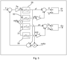
- the exemplified component extractor 23 includes two resonant controllers 29, 31, tuned to a respective one of the first frequency ⁇ l and the second frequency ⁇ u .
- the sum of the outputs of the resonant controllers 29 and 31 y l + nofrz ⁇ y u is subtracted from the vibration-related signal y measured by the sensors 7 and output by the resonant dynamical system 21, i.e., the motor assembly.
- the effect of this closed-loop system is that the resonant controllers 29 and 31 outputs y l and y u , respectively, will extract the first frequency ⁇ l and the second frequency ⁇ u in the vibration-related signal y.
- the transfer function H u ( s ) from y to y u has the opposite properties.
- the component extractor 23 has two resonators 33 and 35 which are not placed in the closed loop. Since these resonators 33, 35 have ⁇ l,u in their numerators in the place of s, they create the quadrature components to the outputs y l,u , i.e., sinusoids that lag the outputs y l,u by 90°.
- the first gain G l and the second gain G u are used to e.g., determine the gain ratio in equation (2).
- the estimated gain G 0 ⁇ of the resonant dynamical system is the modulus of the first gain G l because after a transient, the first gain G l converges to a constant value, whose modulus is the estimated gain G 0 ⁇ .
- the method may comprise a step h) of determining the time delay T of the resonant dynamical system 21 based on an argument of the resonant dynamical system at the resonance frequency ⁇ 0 , i.e., arg ( G l ).
- ⁇ l ⁇ argG l
- argG l ⁇ argG l
- T ⁇ ⁇ ⁇ l ⁇ l .
- the method may comprise a step i) of determining the damping ⁇ of the resonant dynamical system based on the gain ratio, the first frozen frequency value, and the second frozen frequency value.
- the gain ratio is here determined by the first gain ( G l ) at the estimated resonance frequency ( ⁇ 0 ⁇ ), and the second gain ( G u ) at the second frozen frequency value.
- the estimate ⁇ of the damping ⁇ may be obtained by letting ⁇ 0 ⁇ ⁇ l ,
- , giving the estimate ⁇ ⁇ ⁇ ⁇ u 2 ⁇ ⁇ l 2 2 ⁇ u ⁇ l G l G u 2 ⁇ 1
Landscapes
- Engineering & Computer Science (AREA)
- Power Engineering (AREA)
- Control Of Electric Motors In General (AREA)
Abstract
Description
- The present disclosure generally relates to parameter identification of a resonant dynamical system describing a physical system such as an electrical machine assembly.
- A physical system that can be described by a resonant dynamical system is a system that can be set to self-oscillate when stimulated with a frequency close to or at the resonance, or natural, frequency of the system.
- For electrical motors, for example, severe vibrations of the foundation of the electric motor occur when the electrical motor operates at natural frequencies of the mechanical body, i.e., of the entire motor assembly, including the stator, the rotor, motor end plates, and connected load if any, etc.
- Identification of parameters of the resonant dynamical system helps understanding at what frequency or frequencies severe vibrations may occur, which in turn may facilitate avoiding these vibrations.
- Thus, in view of the above an object of the present disclosure is to provide a method which solves or at least mitigates the problems of the prior art.
- There is hence according to a first aspect of the present disclosure provided a method of identifying one or more parameters of a resonant dynamical system describing a physical system, the method comprising: a) simultaneously stimulating the physical system by means of a first frequency below an expected resonance frequency of the resonant dynamical system and a second frequency above the expected resonance frequency, b) increasing the first frequency and decreasing the second frequency, wherein one of the first frequency and the second frequency is set before the other one of the first frequency and the second frequency and is based on a difference between 1 and a gain ratio of a first gain of the resonant dynamical system at the first frequency, and a second gain of the resonant dynamical system at the second frequency, and performing steps a)-b) until a difference between the second frequency and the first frequency is equal to a threshold value, c) freezing the one of the first frequency and the second frequency that in step b) is set after the other frequency when the difference has reached the threshold value, to obtain a first frozen frequency value, d) adjusting the one of the first frequency and the second frequency which is not frozen in step c) to move closer to the first frozen frequency value, and repeating step d) until the gain ratio is within a predetermined acceptable range, or until a predetermined amount of time from the start of the first iteration of step a) has passed, and setting the adjusted first frequency or second frequency in the last iteration in step d) to a second frozen frequency value, and e) estimating a resonance frequency of the resonant dynamical system based on the first frozen frequency value and the second frozen frequency value.
- A quick and accurate method may thus be provided for finding an estimate of the resonance frequency of the resonant dynamical system, and thus for the underlying physical system.
- The resonance frequency may be used for tuning a control system configured to control the physical system and/or for condition monitoring of the physical system.
- The first frequency may be a first angular frequency. The second frequency may be a second angular frequency.
- According to one embodiment step e) involves taking the square root of the product of the first frozen frequency value and the second frozen frequency value to obtain the estimated resonance frequency. Thus, the first frozen frequency value and the second frozen frequency value form the geometric average of the resonance frequency. This follows from the method striving to set to gain ratio to 1. The resonance frequency is thus estimated based on the first frozen frequency value and the second frozen frequency value, invariant of the damping and the time delay of the resonant dynamical system.
- One embodiment comprises f) stimulating the physical system by means of the resonance frequency, and g) determining a gain of the resonant dynamical system at the estimated resonance frequency.
- One embodiment comprises h) determining a time delay of the resonant dynamical system based on an argument of the resonant dynamical system at the estimated resonance frequency.
- One embodiment comprises i) determining a damping of the resonant dynamical system based on the gain ratio, the first frozen frequency value, and the second frozen frequency value, wherein the gain ratio when determining the damping (ζ̂) is determined by the first gain (Gl ) at the estimated resonance frequency

- According to one embodiment the predetermined acceptable range has a lower boundary of at least 0.99 and an upper boundary of at most 1.01.
- According to one embodiment the threshold value is at least one order smaller than the resonance frequency.
- One embodiment comprises determining the first gain and the second gain based on vibration-related measurements of the physical system when stimulated by the first frequency and the second frequency.
- According to one embodiment the physical system is an electrical machine.
- The electrical machine may be motor or a generator.
- According to one embodiment the stimulating involves injecting oscillating incremental torque into the electrical machine.
- According to one embodiment prior to step a) the method comprises simultaneously stimulating the physical system by means of the first frequency and the second frequency below the expected resonance frequency, and adjusting the second frequency until the second frequency is above the expected resonance frequency.
- There is according to a second aspect of the present disclosure provided a control system for identifying parameters of a resonant dynamical system describing a physical system, the control system comprising: processing circuitry, and a storage medium comprising computer code which when executed by the processing circuitry is configured to cause the control system to perform the method of the first aspect.
- There is according to a third aspect provided a system comprising: a physical system, a control system of the second aspect, and an actuator configured to stimulate the physical system, wherein the control system is configured to control the actuator.
- According to one embodiment the physical system is an electrical machine, and the actuator is a power converter. The power converter may be a frequency converter.
- Generally, all terms used in the claims are to be interpreted according to their ordinary meaning in the technical field, unless explicitly defined otherwise herein. All references to "a/an/the element, apparatus, component, means", etc. are to be interpreted openly as referring to at least one instance of the element, apparatus, component, means, etc., unless explicitly stated otherwise.
- Exemplifying embodiments will now be described, with reference to the accompanying drawings, in which:
-
Fig. 1 schematically shows a motor assembly; -
Fig. 2 schematically shows an example of a control system of the motor assembly inFig. 1 ; -
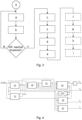
Fig. 3 is a flowchart of a method of reducing vibrations in the motor assembly; and -
Fig. 4 shows functional blocks of the control system; and -
Fig. 5 shows an example of the component extractor of the functional blocks. - The inventive concept will now be described more fully hereinafter with reference to the accompanying drawings, in which exemplifying embodiments are shown. The inventive concept may, however, be embodied in many different forms and should not be construed as limited to the embodiments set forth herein; rather, these embodiments are provided by way of example so that this disclosure will be thorough and complete, and will fully convey the scope of the inventive concept to those skilled in the art. Like numbers refer to like elements throughout the description.
- The method disclosed herein may be used in physical systems that are electrical, mechanical, or electromechanical and which can be modelled by a resonant dynamical system. Such physical systems can be stimulated by an actuator, such as an electrical actuator, e.g., a frequency converter, or a mechanical actuator, to set the physical system in resonance.
- In the following, the method will be exemplified in the context of an electrical machine, in particular a motor system. The electrical machine could alternatively be a generator system.
-
Fig. 1 shows an example of amotor system 1. Themotor system 1 comprises a motor assembly including anelectric motor 3, the foundation on which theelectric motor 3 stands, and the outer cover of theelectric motor 3. Theelectric motor 3 comprises a stator, and a rotor arranged inside the stator and arranged to rotate relative to the stator. - The
motor system 1 also comprises acontrol system 5, apower converter 6, such as a drive, configured to drive theelectric motor 3, and configured to be controlled by thecontrol system 5, and a plurality ofsensors 7. - The motor assembly may also include a load which the
electric motor 3 is configured to drive. - The
sensors 7 are configured to make measurements of a vibration-related parameter such as acceleration, vibrational velocity, displacement, or sound, of themotor system 1. Thesensors 7 may thus for example be accelerometers, displacement sensors, or microphones. Thesensors 7 may for example be arranged to measure horizontal vibration, such as horizontal acceleration, i.e., acceleration in the horizontal plane. -
Fig. 2 schematically depicts a block diagram of an example of thecontrol system 5. Thecontrol system 5 is configured to identify one or more parameters of a resonant dynamical system describing the motor assembly. - The
control system 5 comprises aninput unit 9 configured to receive a vibration-related signal based on measurements from thesensors 7. - According to one example, the
control system 5 may comprise a signal conditioner which converts the measurements to the vibration-related signal. For example, thesensors 7 may be accelerometers, and the signal conditioner may be configured to convert the acceleration to vibrational velocity, which according to an example may be the vibration-related signal. - The
control system 5 comprisesprocessing circuitry 11. Theprocessing circuitry 11 may for example use any combination of one or more of a suitable central processing unit (CPU), multiprocessor, microcontroller, digital signal processor (DSP), application specific integrated circuit (ASIC), field programmable gate arrays (FPGA) etc., capable of executing any herein disclosed operations concerning parameter identification of the resonant dynamical system describing the motor assembly. - The
control system 5 may comprise astorage medium 13. Thestorage medium 13 may comprise a computer program including computer code which when executed by theprocessing circuitry 13 causes thecontrol system 5 to perform a method as disclosed herein. - The
storage medium 13 may for example be embodied as a memory, such as a random access memory (RAM), a read-only memory (ROM), an erasable programmable read-only memory (EPROM), or an electrically erasable programmable read-only memory (EEPROM) and more particularly as a non-volatile storage medium of a device in an external memory such as a USB (Universal Serial Bus) memory or a Flash memory, such as a compact Flash memory. - With reference to
Figs 3-5 , a method of identifying one or more parameters of a resonant dynamical system describing the motor assembly will now be described. - The resonant dynamical system may for example be expressed in the form of a bandpass filter with gain G 0 and time delay e -sT as shown in equation (1) below,

- The input signal u to the resonant dynamical system, and thus to the
electric motor 3, is determined by thecontrol system 5. The input signal u is an oscillating incremental torque reference, which thepower converter 6 uses to generate an oscillating incremental torque. - The method involves simultaneously injecting two frequency components, i.e., a first frequency ωl and a second frequency ωu, into the
electric motor 3 in a step a). - The first frequency ωl is injected below the expected resonance frequency of the resonant dynamical system, and the second frequency ωu is injected above the expected resonance frequency.
- The method may however according to one example initially start with both the first frequency ωl and the second frequency ωu below the expected resonance frequency before the second frequency ωu jumps over the expected resonance frequency to reach step a).
- If the estimated resonance frequency ω0 is set to


- This follows from equation (1). Hereto, invariant of the damping ζ and T in the time delay, the first frequency ωl and the second frequency ωu form the geometric average of the resonance frequency ω0 of the resonant dynamical system. An estimate of the resonance frequency ω0 can thus be obtained immediately as the geometric average once the first gain Gl and the second gain Gu have been determined as soon as the gain ratio is 1 or has converged to be within a predetermined acceptable range, for example having a lower boundary of at least 0.99 and an upper boundary of at most 1.01. Alternatively, because of the presence of noise, it may be better to instead of determining the proximity of the gain ratio to 1, let the gain ratio converge towards 1 for a predetermined amount of time from the start of the first iteration of step a) has passed to determine the resonance frequency ω 0.
- Step a) may involve injecting the first frequency ωl and the second frequency ωu as follows. Based on the first frequency ωl and the second frequency ωu, two rotating complex vectors may be formed as Tl = Atrejθ
l , where θl = ∫ ωldt and Tu = Atrejθu , where θu = ∫ ωudt. The oscillating incremental torque reference u is set as the real part of the sum of these two vectors,
- As shown in
Fig. 4 , thecontrol system 5 comprises a plurality of functional blocks, such as an ωl controller 15 which is configured to generate the first frequency ωl , an ωu controller 17 which is configured to generate the second frequency ωu, asignal injector 19 which injects the oscillating incremental torque reference to the resonant dynamical system represented byblock 21, acomponent extractor 23 arranged to determine the first gain Gl and the second gain Gu, adelay estimator 25, and a dampingestimator 27. - In a step b) the first frequency ωl is increased and the second frequency ωu is decreased. One of the first frequency ωl and the second frequency ωu is set before the other one of the first frequency ωl and the second frequency ωl. The frequency, which is set first, is based on a difference between 1 and the gain ratio of equation (2).
- Step b) is performed by the ωl controller 15 and the ωu controller 17. According to the present example, the ωu controller 17 takes the lead when setting the second frequency ωu, and then the ωl controller 15 follows with setting the first frequency ωl . It could alternatively be the other way around. Thus, according to the present example, the purpose of the ωu controller 17 is to adjust the second frequency ωu such that equation (1) holds. The second frequency ωu can for example be obtained by


Fig. 5 . The ωu controller 17 is enabled when enable=1 and frozen when nofrz=0. The gain component before the integral is set proportional to the difference ωu - ωl between the second frequency ωu and the first frequency ωl in order to have a higher gain initially, when the difference is large. - Steps a)-b) are performed until a difference between the second frequency ωu and the first frequency ωl is equal to or smaller than a threshold value Δω, i.e., ωu - ωl = Δω. This leads to step c) in which the one of the first frequency ωl and the second frequency ωu that in step b) is set after the other frequency is frozen, to obtain a first frozen frequency value. In the present example, the first frequency ωl is thus frozen, resulting in the first frozen frequency value at the frozen frequency.
- The threshold value Δω is according to one example not smaller than 20 rad/s. This prevents the first frequency ωl and the second frequency ωu from being inseparable by the
component extractor 23. - In a step d) the one of the first frequency ωl and the second frequency ωu which is not frozen in step c) is adjusted to move closer to the first frozen frequency value. Step d) is repeated until the gain ratio in equation (1) is within the predetermined acceptable range, or until a predetermined amount of time from the start of the first iteration of step a) has passed. Further the adjusted first frequency or second frequency in the last iteration in step d) is set to a second frozen frequency value. In the present example the adjusting, repeating, and setting in step d) is for the second frequency ωu.
- The flag nofrz is changed from 1 to 0 when the ωu controller 17 has converged, i.e., when the gain ratio in equation (1) is within the predetermined acceptable range or the predetermined amount of time from the start of the first iteration of step a) has passed, at which time it is expected that the ωu controller 17 has converged.
- The ωl controller 15 is configured to adjust the first frequency ωl so that it tends towards the second frequency ωu, which according to the present example is set first. The ωl controller 15 is frozen when the control error eω = ωu - ωl < Δω, resulting in the first frozen frequency value. The freezing can for example be implemented by applying a dead-zone (DZ) [-Δω, Δω] to the control error e ω, giving


- Thus, when the flag nofrz drops to zero, the first frequency ωl is set as the geometric average of the outputs of the ωl controller 15 and the ωu controller 17, which are both frozen at this stage.
- Hereto, in a step e) the resonance frequency

resonant dynamical system 21 is estimated based on the first frozen frequency value and the second frozen frequency value. - When the estimated resonance frequency

power converter 6 injects the oscillating incremental torque reference u, based on the estimated resonance frequency. Theelectric motor 3 is thus stimulated by the resonance frequency. Further, a step g) may involve determining a gain of theresonant dynamical system 21 at the resonance frequency. This is done by thecomponent extractor 23, an example of which is shown in more detail inFig. 5 . - The exemplified
component extractor 23 includes tworesonant controllers resonant controllers 29 and 31 yl + nofrz · yu is subtracted from the vibration-related signal y measured by thesensors 7 and output by theresonant dynamical system 21, i.e., the motor assembly. The effect of this closed-loop system is that theresonant controllers - In addition, the
component extractor 23 has tworesonators resonators - The multiplication by nofrz in the input to the
resonant controller 31 and theresonator 35, as well as in the feedback of the output yu, freezes Yu to a static complex sinusoid when nofrz=0. It has been found empirically that a suitable selection of the constant αe is in the range of 10% of the resonance frequency ω 0 but not larger than 30 rad/s. - With Yl and Yu as the outputs of the
component extractor 23, division respectively by Tl and Tu is made to cancel the oscillations at respectively the first frequency ωl and the second frequency ωl , leaving the corresponding resonant dynamical system frequency responses, i.e., the first gain Gl and the second gain Gu
- The first gain Gl and the second gain Gu are used to e.g., determine the gain ratio in equation (2). The estimated gain


- According to one example, the method may comprise a step h) of determining the time delay T of the
resonant dynamical system 21 based on an argument of the resonant dynamical system at the resonance frequency ω 0, i.e., arg (Gl ). Here, one may set

- According to one example, the method may comprise a step i) of determining the damping ζ of the resonant dynamical system based on the gain ratio, the first frozen frequency value, and the second frozen frequency value. The gain ratio is here determined by the first gain (Gl ) at the estimated resonance frequency (


- The inventive concept has mainly been described above with reference to a few examples. However, as is readily appreciated by a person skilled in the art, other embodiments than the ones disclosed above are equally possible within the scope of the inventive concept, as defined by the appended claims.
Claims (14)
- Method of identifying one or more parameters of a resonant dynamical system describing a physical system, the method comprising:a) simultaneously stimulating the physical system by means of a first frequency (ωl ) below an expected resonance frequency (ω 0) of the resonant dynamical system and a second frequency (ω u) above the expected resonance frequency (ω 0),b) increasing the first frequency (ωl ) and decreasing the second frequency (ω u), wherein one of the first frequency (ωl ) and the second frequency (ω u) is set before the other one of the first frequency (ωl ) and the second frequency (ωu ) and is based on a difference between 1 and a gain ratio of a first gain (Gl ) of the resonant dynamical system at the first frequency (ωl ), and a second gain (Gu ) of the resonant dynamical system at the second frequency (ωu ), and performing steps a)-b) until a difference between the second frequency (ω u) and the first frequency (ωl ) is equal to a threshold value,c) freezing the one of the first frequency (ωl ) and the second frequency (ωu ) that in step b) is set after the other frequency when the difference has reached the threshold value, to obtain a first frozen frequency value,d) adjusting the one of the first frequency (ωl ) and the second frequency (ωu ) which is not frozen in step c) to move closer to the first frozen frequency value, and repeating step d) until the gain ratio is within a predetermined acceptable range, or until a predetermined amount of time from the start of the first iteration of step a) has passed, and setting the adjusted first frequency (ωl ) or the second frequency (ωu ) in the last iteration in step d) to a second frozen frequency value, ande) estimating a resonance frequency (

- Method as claimed in claim 1, wherein step e) involves taking the square root of the product of the first frozen frequency value and the second frozen frequency value to obtain the estimated resonance frequency (

- Method as claimed in claim 1 or 2, comprising f) stimulating the physical system by means of the resonance frequency (ω 0), and g) determining a gain (


- Method as claimed in claim 3, comprising h) determining a time delay (T̂) of the resonant dynamical system based on an argument of the resonant dynamical system at the estimated resonance frequency (

- Method as claimed in claim 3 or 4, comprising i) determining a damping (ζ̂) of the resonant dynamical system based on the gain ratio, the first frozen frequency value, and the second frozen frequency value, wherein the gain ratio when determining the damping (ζ̂) is determined by the first gain (Gl ) at the estimated resonance frequency (

- Method as claimed in any of the preceding claims, wherein the predetermined acceptable range has a lower boundary of at least 0.99 and an upper boundary of at most 1.01.
- Method as claimed in any of the preceding claims, wherein the threshold value is at least one order smaller than the resonance frequency.
- Method as claimed in any of the preceding claims, comprising determining the first gain (Gl ) and the second gain (Gu ) based on vibration-related measurements of the physical system when stimulated by the first frequency (ωl ) and the second frequency (ωu ).
- Method as claimed in any of the preceding claims, wherein the physical system is an electrical machine.
- Method as claimed in claim 9, wherein the stimulating involves injecting oscillating incremental torque into the electrical machine.
- Method as claimed in any of the preceding claims, wherein prior to step a) the method comprises simultaneously stimulating the physical system by means of the first frequency (ωl ) and the second frequency (ωu ) below the expected resonance frequency, and adjusting the second frequency (ω u) until the second frequency (ωu ) is above the expected resonance frequency.
- A control system (5) for identifying parameters of a resonant dynamical system describing a physical system, the control system (5) comprising:processing circuitry (11), anda storage medium (13) comprising computer code which when executed by the processing circuitry (11) is configured to cause the control system (5) to perform the method as claimed in any of the preceding claims.
- System comprising:a physical system,a control system (5) as claimed in claim 12, andan actuator configured to stimulate the physical system, wherein the control system (5) is configured to control the actuator.
- System as claimed in claim 13, wherein the physical system is an electrical machine, and the actuator is a power converter (6).
Priority Applications (1)
| Application Number | Priority Date | Filing Date | Title |
|---|---|---|---|
| EP23181621.6A EP4485793A1 (en) | 2023-06-27 | 2023-06-27 | Method of identifying parameters of a resonant dynamical system |
Applications Claiming Priority (1)
| Application Number | Priority Date | Filing Date | Title |
|---|---|---|---|
| EP23181621.6A EP4485793A1 (en) | 2023-06-27 | 2023-06-27 | Method of identifying parameters of a resonant dynamical system |
Publications (1)
| Publication Number | Publication Date |
|---|---|
| EP4485793A1 true EP4485793A1 (en) | 2025-01-01 |
Family
ID=87003134
Family Applications (1)
| Application Number | Title | Priority Date | Filing Date |
|---|---|---|---|
| EP23181621.6A Pending EP4485793A1 (en) | 2023-06-27 | 2023-06-27 | Method of identifying parameters of a resonant dynamical system |
Country Status (1)
| Country | Link |
|---|---|
| EP (1) | EP4485793A1 (en) |
Citations (3)
| Publication number | Priority date | Publication date | Assignee | Title |
|---|---|---|---|---|
| CA2253586A1 (en) * | 1996-07-01 | 1998-01-08 | Richard K. Karlquist | Bridge-stabilized oscillator circuit and method |
| JP2000028624A (en) * | 1998-05-04 | 2000-01-28 | Internatl Business Mach Corp <Ibm> | Scanning force microscope and control of movement for probe tip thereof |
| EP2510891A1 (en) * | 2011-04-15 | 2012-10-17 | Covidien AG | Battery-powered hand-held ultrasonic surgical cautery cutting device |
-
2023
- 2023-06-27 EP EP23181621.6A patent/EP4485793A1/en active Pending
Patent Citations (3)
| Publication number | Priority date | Publication date | Assignee | Title |
|---|---|---|---|---|
| CA2253586A1 (en) * | 1996-07-01 | 1998-01-08 | Richard K. Karlquist | Bridge-stabilized oscillator circuit and method |
| JP2000028624A (en) * | 1998-05-04 | 2000-01-28 | Internatl Business Mach Corp <Ibm> | Scanning force microscope and control of movement for probe tip thereof |
| EP2510891A1 (en) * | 2011-04-15 | 2012-10-17 | Covidien AG | Battery-powered hand-held ultrasonic surgical cautery cutting device |
Similar Documents
| Publication | Publication Date | Title |
|---|---|---|
| KR101841134B1 (en) | Dynamometer control device and method for estimating moment of inertia using same | |
| US9423782B2 (en) | Motor drive device | |
| CN101207359B (en) | Method of operating a wind power plant during sudden voltage changes in a power grid | |
| JP2021508059A (en) | Test benches and methods for performing a dynamic test course for test structures | |
| US10579038B2 (en) | Control apparatus of an electric motor | |
| CN107387382B (en) | Compressor amplitude control method, compressor system and refrigeration equipment | |
| US10734933B2 (en) | Motor control apparatus | |
| CN106574605A (en) | Active promotion of wind turbine tower oscillations | |
| WO2018090782A1 (en) | Online identification method and apparatus for motor stator resistance, and motor control system | |
| CN106323449B (en) | A kind of rotating machinery shafting torsional oscillation fault monitoring method under frequency control driving | |
| EP4485793A1 (en) | Method of identifying parameters of a resonant dynamical system | |
| WO2018090783A1 (en) | Method for online identification of motor stator resistance, apparatus, and motor control system | |
| CN101536305A (en) | Motor control device, and its control method | |
| US12068607B2 (en) | System and method for automated tuning/configuring of a power system stabilizer (PSS) in a digital excitation control system | |
| Zhang et al. | Analysis of frequency characteristics of MEMS piezoelectric cantilever beam based energy harvester | |
| CN104007317A (en) | Method and device for obtaining frequency characteristic of servo system | |
| EP3875661B1 (en) | Method to estimate a load behavior in a laundry treatment machine | |
| EP4439968A1 (en) | Method of identifying parameters of a motor system | |
| Simakov et al. | Dynamic modes of electromechanical unbalance vibration exciter with induction motor under vector control | |
| Willie et al. | Structural and torsional vibration analysis of a dry screw compressor | |
| CN107425761A (en) | Permagnetic synchronous motor low frequency control method, device, compressor and air conditioner | |
| CN113008359A (en) | Method, system and apparatus for determining a resonant frequency of a mechanical system | |
| CN120628271A (en) | Torsional resonance frequency measurement method of electric drive system based on active torque injection | |
| EP4148977B1 (en) | System and method for obtaining an estimated output power of an electric motor | |
| CN114070158A (en) | Control method of motor based on torque information, motor and storage medium |
Legal Events
| Date | Code | Title | Description |
|---|---|---|---|
| PUAI | Public reference made under article 153(3) epc to a published international application that has entered the european phase |
Free format text: ORIGINAL CODE: 0009012 |
|
| STAA | Information on the status of an ep patent application or granted ep patent |
Free format text: STATUS: THE APPLICATION HAS BEEN PUBLISHED |
|
| AK | Designated contracting states |
Kind code of ref document: A1 Designated state(s): AL AT BE BG CH CY CZ DE DK EE ES FI FR GB GR HR HU IE IS IT LI LT LU LV MC ME MK MT NL NO PL PT RO RS SE SI SK SM TR |
|
| STAA | Information on the status of an ep patent application or granted ep patent |
Free format text: STATUS: REQUEST FOR EXAMINATION WAS MADE |
|
| 17P | Request for examination filed |
Effective date: 20250625 |
|
| RIN1 | Information on inventor provided before grant (corrected) |
Inventor name: HARNEFORS, LENNART Inventor name: IKRAM UL HAQ, OMER Inventor name: BOSGA, SJOERD Inventor name: SAARINEN, KARI |
|
| GRAP | Despatch of communication of intention to grant a patent |
Free format text: ORIGINAL CODE: EPIDOSNIGR1 |
|
| STAA | Information on the status of an ep patent application or granted ep patent |
Free format text: STATUS: GRANT OF PATENT IS INTENDED |
|
| INTG | Intention to grant announced |
Effective date: 20251009 |
|
| RIN1 | Information on inventor provided before grant (corrected) |
Inventor name: HARNEFORS, LENNART Inventor name: IKRAM UL HAQ, OMER Inventor name: BOSGA, SJOERD Inventor name: SAARINEN, KARI |
|
| GRAJ | Information related to disapproval of communication of intention to grant by the applicant or resumption of examination proceedings by the epo deleted |
Free format text: ORIGINAL CODE: EPIDOSDIGR1 |
|
| STAA | Information on the status of an ep patent application or granted ep patent |
Free format text: STATUS: REQUEST FOR EXAMINATION WAS MADE |
|
| GRAP | Despatch of communication of intention to grant a patent |
Free format text: ORIGINAL CODE: EPIDOSNIGR1 |
|
| STAA | Information on the status of an ep patent application or granted ep patent |
Free format text: STATUS: GRANT OF PATENT IS INTENDED |
|
| INTC | Intention to grant announced (deleted) | ||
| INTG | Intention to grant announced |
Effective date: 20260304 |