EP4485791A1 - Motor control device - Google Patents
Motor control device Download PDFInfo
- Publication number
- EP4485791A1 EP4485791A1 EP23182621.5A EP23182621A EP4485791A1 EP 4485791 A1 EP4485791 A1 EP 4485791A1 EP 23182621 A EP23182621 A EP 23182621A EP 4485791 A1 EP4485791 A1 EP 4485791A1
- Authority
- EP
- European Patent Office
- Prior art keywords
- motor
- electronic circuit
- control device
- control
- motor control
- Prior art date
- Legal status (The legal status is an assumption and is not a legal conclusion. Google has not performed a legal analysis and makes no representation as to the accuracy of the status listed.)
- Pending
Links
Images

Classifications
-
- H—ELECTRICITY
- H02—GENERATION; CONVERSION OR DISTRIBUTION OF ELECTRIC POWER
- H02P—CONTROL OR REGULATION OF ELECTRIC MOTORS, ELECTRIC GENERATORS OR DYNAMO-ELECTRIC CONVERTERS; CONTROLLING TRANSFORMERS, REACTORS OR CHOKE COILS
- H02P7/00—Arrangements for regulating or controlling the speed or torque of electric DC motors
- H02P7/06—Arrangements for regulating or controlling the speed or torque of electric DC motors for regulating or controlling an individual DC dynamo-electric motor by varying field or armature current
- H02P7/18—Arrangements for regulating or controlling the speed or torque of electric DC motors for regulating or controlling an individual DC dynamo-electric motor by varying field or armature current by master control with auxiliary power
- H02P7/24—Arrangements for regulating or controlling the speed or torque of electric DC motors for regulating or controlling an individual DC dynamo-electric motor by varying field or armature current by master control with auxiliary power using discharge tubes or semiconductor devices
- H02P7/28—Arrangements for regulating or controlling the speed or torque of electric DC motors for regulating or controlling an individual DC dynamo-electric motor by varying field or armature current by master control with auxiliary power using discharge tubes or semiconductor devices using semiconductor devices
- H02P7/285—Arrangements for regulating or controlling the speed or torque of electric DC motors for regulating or controlling an individual DC dynamo-electric motor by varying field or armature current by master control with auxiliary power using discharge tubes or semiconductor devices using semiconductor devices controlling armature supply only
- H02P7/292—Arrangements for regulating or controlling the speed or torque of electric DC motors for regulating or controlling an individual DC dynamo-electric motor by varying field or armature current by master control with auxiliary power using discharge tubes or semiconductor devices using semiconductor devices controlling armature supply only using static converters, e.g. AC to DC
-
- H—ELECTRICITY
- H02—GENERATION; CONVERSION OR DISTRIBUTION OF ELECTRIC POWER
- H02P—CONTROL OR REGULATION OF ELECTRIC MOTORS, ELECTRIC GENERATORS OR DYNAMO-ELECTRIC CONVERTERS; CONTROLLING TRANSFORMERS, REACTORS OR CHOKE COILS
- H02P5/00—Arrangements specially adapted for regulating or controlling the speed or torque of two or more electric motors
- H02P5/68—Arrangements specially adapted for regulating or controlling the speed or torque of two or more electric motors controlling two or more DC dynamo-electric motors
-
- B—PERFORMING OPERATIONS; TRANSPORTING
- B60—VEHICLES IN GENERAL
- B60R—VEHICLES, VEHICLE FITTINGS, OR VEHICLE PARTS, NOT OTHERWISE PROVIDED FOR
- B60R16/00—Electric or fluid circuits specially adapted for vehicles and not otherwise provided for; Arrangement of elements of electric or fluid circuits specially adapted for vehicles and not otherwise provided for
- B60R16/02—Electric or fluid circuits specially adapted for vehicles and not otherwise provided for; Arrangement of elements of electric or fluid circuits specially adapted for vehicles and not otherwise provided for electric constitutive elements
- B60R16/023—Electric or fluid circuits specially adapted for vehicles and not otherwise provided for; Arrangement of elements of electric or fluid circuits specially adapted for vehicles and not otherwise provided for electric constitutive elements for transmission of signals between vehicle parts or subsystems
- B60R16/0231—Circuits relating to the driving or the functioning of the vehicle
-
- H—ELECTRICITY
- H02—GENERATION; CONVERSION OR DISTRIBUTION OF ELECTRIC POWER
- H02K—DYNAMO-ELECTRIC MACHINES
- H02K11/00—Structural association of dynamo-electric machines with electric components or with devices for shielding, monitoring or protection
- H02K11/20—Structural association of dynamo-electric machines with electric components or with devices for shielding, monitoring or protection for measuring, monitoring, testing, protecting or switching
- H02K11/21—Devices for sensing speed or position, or actuated thereby
- H02K11/215—Magnetic effect devices, e.g. Hall-effect or magneto-resistive elements
-
- H—ELECTRICITY
- H02—GENERATION; CONVERSION OR DISTRIBUTION OF ELECTRIC POWER
- H02P—CONTROL OR REGULATION OF ELECTRIC MOTORS, ELECTRIC GENERATORS OR DYNAMO-ELECTRIC CONVERTERS; CONTROLLING TRANSFORMERS, REACTORS OR CHOKE COILS
- H02P6/00—Arrangements for controlling synchronous motors or other dynamo-electric motors using electronic commutation dependent on the rotor position; Electronic commutators therefor
- H02P6/08—Arrangements for controlling the speed or torque of a single motor
- H02P6/085—Arrangements for controlling the speed or torque of a single motor in a bridge configuration
-
- H—ELECTRICITY
- H02—GENERATION; CONVERSION OR DISTRIBUTION OF ELECTRIC POWER
- H02P—CONTROL OR REGULATION OF ELECTRIC MOTORS, ELECTRIC GENERATORS OR DYNAMO-ELECTRIC CONVERTERS; CONTROLLING TRANSFORMERS, REACTORS OR CHOKE COILS
- H02P7/00—Arrangements for regulating or controlling the speed or torque of electric DC motors
- H02P7/03—Arrangements for regulating or controlling the speed or torque of electric DC motors for controlling the direction of rotation of DC motors
- H02P7/04—Arrangements for regulating or controlling the speed or torque of electric DC motors for controlling the direction of rotation of DC motors by means of a H-bridge circuit
-
- H—ELECTRICITY
- H02—GENERATION; CONVERSION OR DISTRIBUTION OF ELECTRIC POWER
- H02P—CONTROL OR REGULATION OF ELECTRIC MOTORS, ELECTRIC GENERATORS OR DYNAMO-ELECTRIC CONVERTERS; CONTROLLING TRANSFORMERS, REACTORS OR CHOKE COILS
- H02P7/00—Arrangements for regulating or controlling the speed or torque of electric DC motors
- H02P7/06—Arrangements for regulating or controlling the speed or torque of electric DC motors for regulating or controlling an individual DC dynamo-electric motor by varying field or armature current
- H02P7/18—Arrangements for regulating or controlling the speed or torque of electric DC motors for regulating or controlling an individual DC dynamo-electric motor by varying field or armature current by master control with auxiliary power
- H02P7/24—Arrangements for regulating or controlling the speed or torque of electric DC motors for regulating or controlling an individual DC dynamo-electric motor by varying field or armature current by master control with auxiliary power using discharge tubes or semiconductor devices
- H02P7/28—Arrangements for regulating or controlling the speed or torque of electric DC motors for regulating or controlling an individual DC dynamo-electric motor by varying field or armature current by master control with auxiliary power using discharge tubes or semiconductor devices using semiconductor devices
- H02P7/285—Arrangements for regulating or controlling the speed or torque of electric DC motors for regulating or controlling an individual DC dynamo-electric motor by varying field or armature current by master control with auxiliary power using discharge tubes or semiconductor devices using semiconductor devices controlling armature supply only
- H02P7/29—Arrangements for regulating or controlling the speed or torque of electric DC motors for regulating or controlling an individual DC dynamo-electric motor by varying field or armature current by master control with auxiliary power using discharge tubes or semiconductor devices using semiconductor devices controlling armature supply only using pulse modulation
- H02P7/2913—Arrangements for regulating or controlling the speed or torque of electric DC motors for regulating or controlling an individual DC dynamo-electric motor by varying field or armature current by master control with auxiliary power using discharge tubes or semiconductor devices using semiconductor devices controlling armature supply only using pulse modulation whereby the speed is regulated by measuring the motor speed and comparing it with a given physical value
-
- H—ELECTRICITY
- H04—ELECTRIC COMMUNICATION TECHNIQUE
- H04L—TRANSMISSION OF DIGITAL INFORMATION, e.g. TELEGRAPHIC COMMUNICATION
- H04L12/00—Data switching networks
- H04L12/02—Details
- H04L12/10—Current supply arrangements
-
- H—ELECTRICITY
- H04—ELECTRIC COMMUNICATION TECHNIQUE
- H04L—TRANSMISSION OF DIGITAL INFORMATION, e.g. TELEGRAPHIC COMMUNICATION
- H04L12/00—Data switching networks
- H04L12/28—Data switching networks characterised by path configuration, e.g. LAN [Local Area Networks] or WAN [Wide Area Networks]
- H04L12/40—Bus networks
- H04L2012/40208—Bus networks characterized by the use of a particular bus standard
- H04L2012/40215—Controller Area Network CAN
Definitions
- the present disclosure relates generally to a motor control device, e.g. used in automotive or industrial environment.
- E/E Electronic/Electronic
- ECU Electronic Control Unit
- a steering column position control of a car requires at least one separate and dedicated ECU to control a first DC motor in X-direction (to adjust the height of the mechanical part of the column) and a second DC motor in Z-direction (to adjust the inclination of the mechanical part of the column).
- the control of these two DC motors is handled asynchrony (e.g. first along the X-axis and after along the Z-axis) as the control data sent from a main ECU to the dedicated ECU are transmitted using a LIN (Local Interconnect Network) bus protocol, which is limited to around 20 kBaud.
- LIN Local Interconnect Network
- car's light level control (light position adjustment) which requires a separate and dedicated ECU to control the lights position.
- the communication between this dedicated ECU and a main ECU is done via a CAN (Controller Area Network) or CAN FD (Controller Area Network Flexible Data-Rate) bus which is limited to around 1 MBaud.
- CAN Controller Area Network
- CAN FD Controller Area Network Flexible Data-Rate
- the motor driver electronic circuit comprises a H-bridge circuit.
- the H-bridge circuit comprises four MOSFETs
- the motor driver electronic circuit comprises a gate driver circuit electrically coupled to gates of the four MOSFETs.
- the motor control device further comprises a support to which the motor driver electronic circuit and the control electronic circuit are mechanically secured, and the motor control device further comprises the motor position sensor which is mechanically secured to the support.
- the motor position sensor comprises at least one Hall sensor.
- control electronic circuit is configured to send, to the motor driver electronic circuit, at least one motor control signal defining at least one position of the motor according to at least one signal sent by the motor position sensor to the control electronic circuit.
- control electronic circuit further comprises a Serial Peripheral Interface type communication port configured to be coupled to the main ECU.
- control electronic circuit comprises control logic elements forming a state machine configured to implement at least one of the following functions:
- Another particular embodiment proposes a motor assembly comprising at least one motor and at least one motor control device as previously described, wherein the motor comprises at least one control input electrically coupled to at least one output of the motor driver electronic circuit of the motor control device.
- the motor is a DC brushed motor.
- the motor assembly further comprises at least one of the following elements configured to control the position of the motor: magnetic disk, optical encoder, closed loop control.
- Another particular embodiment proposes a vehicle network system comprising at least several main ECUs, at least one gateway through which the several main ECUs are electrically interconnected, and several motor assemblies as previously disclosed, wherein the CAN type transceivers of the motor assemblies are electrically and directly coupled to the main ECUs.
- the several main ECUs, the at least one gateway and the several motor assemblies are arranged and electrically coupled according to a domain or zonal architecture.
- the vehicle network system forms an Electrical/Electronic car network.
- a direct communication or a direct electrical connection or coupling between a CAN type transceiver and a main ECU may be understand as corresponding to communication or connection or coupling implemented without an intermediate ECU between the CAN type transceiver and the main ECU.
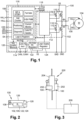
- the motor control device 100 comprises at least a motor driver electronic circuit 102 configured to be electrically coupled to at least one motor 104 and to drive it.
- the motor 104 corresponds to a DC brushed motor.
- the motor 104 may comprise, as in the configuration shown in Figure 1 , two electrical inputs connected to outputs of the motor driver electronic circuit 102 (labeled "M+" and "M-" in Figure 1 ).
- the motor control device 100 also comprises a control electronic circuit 106 electrically coupled to the motor driver electronic circuit 102, and configured to control the motor driver electronic circuit 102 and to be electrically coupled to a motor position sensor 108.
- a control electronic circuit 106 electrically coupled to the motor driver electronic circuit 102, and configured to control the motor driver electronic circuit 102 and to be electrically coupled to a motor position sensor 108.
- the electrical coupling between the control electronic circuit 106 and the motor position sensor 108 is obtained between the inputs/outputs labeled "HALL+" and "HALL-" of the control electronic circuit 106 and terminals of the motor position sensor 108.
- the motor position sensor 108 comprises at least one Hall sensor. More generally, the motor position sensor 108 may comprise any other component or circuit able to determine the position of the motor 104, i.e. the position of the rotor of the motor 104 in the case of a DC motor.
- control electronic circuit 106 may be configured to send, to the motor driver electronic circuit 102, at least one motor control signal defining at least one position of the motor 104 according to at least one signal sent by the motor position sensor 108 to the control electronic circuit 106.
- the motor driver electronic circuit 102 may comprise a H-bridge circuit intended to send motor control signals to the motor 104.
- the H-bridge circuit may comprise four MOSFETs 110.1 - 110.4, the gates of which being electrically coupled to a gate driver circuit 112 belonging to the motor driver electronic circuit 102.
- the motor driver electronic circuit 102 may control the motor 104 in both directions.
- This H-bridge circuit may be fully integrated with the other elements of the motor control device 100.
- the gate driver circuit 112 may comprise several electronic and logic components to control the H-bridge circuit and to communicate with the control electronic circuit 106.
- the motor driver electronic circuit 102 may implement several functions related to the motor positioning or motor parameter sensing: positioning in an absolute or relative or stored position, set soft stop or soft start position, reference run, get voltage, current and temperature, etc. These different functions correspond to classical known functions to control a DC motor and are thus not described in details here. In the example embodiment shown in Figure 1 , these functions may be implemented by the gate driver circuit 112.
- the motor driver electronic circuit 102 may comprise components / circuits different than those above described.
- the control electronic circuit 106 comprises a CAN type transceiver 114 configured to directly communicate with at least one main ECU (not shown in Figure 1 ) which is external to the motor control device 100.
- This communication between the control electronic circuit 106 and the main ECU is implemented using a commander and responder (also known as "master/slave") CAN type communication protocol, the control electronic circuit 106 being configured to act as a responder node during a communication with the main ECU.
- the commander and responder CAN type communication protocol may be implemented according to the "CAN FD Light" specification published by the CAN in Automation (CiA) group under the reference "CiA 604-1".
- the CAN FD Light link between the main ECU and the CAN type transceiver 114 is formed by two wires connected to the inputs/outputs labeled "CANL" and "CANH" of the control electronic circuit 106 on one side, and to the main ECU on the other side.
- control electronic circuit 106 may further comprise a Serial Peripheral Interface (SPI) type communication port configured to be coupled to the main ECU.
- SPI Serial Peripheral Interface
- the SPI communication port of the control electronic circuit 106 corresponds to the four inputs/outputs labeled "CSN" (Chip Select Node), "SDI” (Serial Data Input), "SDO” (Serial Data Output) and "SCK” (Serial Clock).
- CSN Chip Select Node
- SDI Serial Data Input
- SDO Serial Data Output
- SCK Serial Clock
- the control electronic circuit 106 may comprise control logic elements 116 forming a state machine dedicated to the management of the different functions fulfilled by the motor control device 100.
- these control logic elements 116 are configured to implement several functions:
- control logic elements 116 may be programmable (PWM duty cycle, number of Hall pulses per rotation, etc.).
- control logic elements 116 may implement only a part of the above-mentioned functions, or function(s) different as those above described.
- control logic elements 116 may also comprise different registers suitable for the different functions fulfilled by the control logic elements 116.
- the control electronic circuit 106 may also comprise an Analog-Digital Converter 118, e.g. used for the motor current sensor function.
- the control electronic circuit 106 may also comprise a Non-Volatile Memory 120 which may be used by the control logic elements 116, e.g. to store values of position(s) of the motor 104 (position left / right) or driving parameters of the motor 104 (e.g. soft start, soft stop of the motor).
- a Non-Volatile Memory 120 may be used by the control logic elements 116, e.g. to store values of position(s) of the motor 104 (position left / right) or driving parameters of the motor 104 (e.g. soft start, soft stop of the motor).
- the motor control device 100 also comprises voltage regulators 122, 124 configured to select / adapt the supply voltage applied as input on the motor control device 100 to voltage(s) adapted to the motor driver electronic circuit 102 and the control electronic circuit 106 (e.g. 5 V and 12 V).
- voltage regulators 122, 124 configured to select / adapt the supply voltage applied as input on the motor control device 100 to voltage(s) adapted to the motor driver electronic circuit 102 and the control electronic circuit 106 (e.g. 5 V and 12 V).
- the motor control device 100 may comprise an "enable” input (labeled “EN” in Figure 1 ) in order to activate or not the motor control device 100 according to the value of the signal applied on this input.
- This input may be used to handle wake-up and standby modes of the motor control device 100. If this function is not used, it is possible to directly connect this EN input to the power supply.
- the power supply provided to the motor control device 100 on the VS pin may be between 4 V and 40 V (absolute maximum ratings), or between 6 V and 28 V (operating range), depending on the voltage required for the power driving of the motor 104.
- the motor control device 100 may support DC-motor currents up to 15A.
- the motor control device 100 may correspond to a combination of a motor control state machine with an H-Bridge power stage, with a certain programmability of the motor control via a CAN FD Light interface.
- the motor control device 100 may thus form a smart motor controller with a CAN FD Light interface, which may be directly controlled by at least one main ECU, e.g. zonal or domain ECU, and which may directly communicate with the main ECU, in a decentralized manner.
- the previously described elements of the motor control device 100 may be integrated in a single electronic chip, e.g. as a silicon-based integrated circuit.
- the motor control device 100 may further comprise a support 126, e.g. a PCB (Printed Circuit Board), to which the previously described elements of the motor control device 100 (motor driver electronic circuit 102, control electronic circuit 106, voltage regulators 122, 124) are mechanically secured.
- a support 126 e.g. a PCB (Printed Circuit Board)
- the one or several electronic chips e.g. silicon electronic chips, including these elements may be electrically and mechanically coupled to the support 126.
- Circuitries 102, 106, 122, 124 are thus embedded inside one package formed by the motor control device 100.
- the motor position sensor 108 may also be mechanically secured to the support 126.
- the support 126 may include the electrical connections between the motor position sensor 108 and the control electronic circuit 106.
- the motor control device 100 may also comprises an electrical connector 128 mechanically secured to the support 126 and configured to be electrically coupled to the motor 104 (thus including the outputs "M+" and "M-" shown in Figure 1 ).
- Figure 3 schematically illustrates an example of a motor assembly 200 comprising two motor control devices 100 according to one particular embodiment.
- the motor assembly 200 is used to mechanically control the position of a steering column of a car.
- the motor assembly 200 may comprise two motors 202 which, in this particular configuration, correspond to DS brushed motors.
- Each of the two motors 202 comprises at least one control input electrically coupled to at least one output of the motor driver electronic circuit 102 of one of the motor control devices 100 (corresponding to the outputs "M+" and "M-" previously described in relation with Figure 1 ).
- one of the two motors 202 may be configured to control the position of a mechanical part 204 of the steering column according to an X-axis (height adjustment of the mechanical part 204), and the other of the two motors 202 may be configured to control the position of the mechanical part 204 of the steering column according to the Z-axis (inclination adjustment of the mechanical part 204) .
- Each of the motor control devices 100 of the motor assembly 200 is coupled to a main ECU 206.
- the electrical coupling between the main ECU 206 and the motor control devices 100 are symbolically shown with dotted lines. This coupling may correspond to several wires, e.g. at least four wires: supply voltage (e.g. equal to 12V), ground, CANL, CANH. However, these connections may comprise more wires, e.g. if the motor control devices 100 are also coupled to the main ECU 206 with LIN connections, or if the "enable" function of the motor control devices 100 is used.
- each of the motor control devices 100 are similar as that previously described in relation with Figure 2 , the support 126 of each motor control device 100 may be integrated inside the plastic housing of the associated motor 202.
- the motor control device 100 may thus be combined with the motor controlled by the motor control device 100 as part of the connector of the motor.
- the motor assembly 200 may comprise at least one of the following elements configured to more precisely control the position of the motor(s): magnetic disk, optical encoder, closed loop control for servo functionality.
- a first example of a vehicle network system 300 is schematically shown in Figure 4 .
- the vehicle network system 300 corresponds to an E/E car network with a domain architecture.
- the vehicle network system 300 comprises several main ECUs 206 interconnected through a gateway 302.
- the vehicle network system 300 also comprises several sensors, actuators and motors symbolically represented as small rectangles designated by the reference 304.
- each main ECU 206 is dedicated to the control of sensors, actuators and motors used for the same domain or application (connectivity, driving, comfort, etc.).
- Sensors, actuators and motors are coupled to the main ECUs 206.
- the sensors, actuators and motors belonging to a same domain may be coupled to the same main ECU 206.
- one or several of the motors are each controlled by a motor control device 100.
- the CAN type transceivers 114 of these motor control devices 100 are electrically and directly coupled to the main ECUs 206.
- FIG. 5 A second example of a vehicle network system 400 according to a particular embodiment is schematically shown in Figure 5 .
- the vehicle network system 400 corresponds to an E/E car network having a zonal architecture.
- the vehicle network system 400 comprises several main ECUs (not individually referenced in Figure 5 ), each of main ECUs being dedicated to one zone of the vehicle network system 400.
- the vehicle network system 400 also comprises several sensors, actuators and motors symbolically represented as small rectangles designated by the reference 406.
- the sensors, actuators, motors and ECU(s) belonging to the same zone and dedicating to sensing and actuation in this zone are electrically interconnected one to the other through a zone gateway 402 (four zone gateways 402 are shown in Figure 5 ).
- the different zone gateways 402 of the vehicle network system 400 are electrically interconnected one to the other either directly or through a central gateway 404.
- the motor control device 100 thanks to the use of a commander and responder CAN type communication protocol between the motor control device 100 and the main ECU (e.g. CAN FD Light protocol), several motors may be controlled synchronously (e.g. two at the same time).
- the commander and responder CAN type communication protocol enables fast reaction times which improve time depending safety mechanism (reaction and position time).
- the cost of the E/E car network may be reduced thanks to the less numbers of ECUs needed in the network.
- the proposed motor control device 100 may have the capability to directly support zonal car architecture (as a "Smart Sensor"). With the proposed motor control device 100, no supplemental software is needed as the motor control features are embedded inside the electronic control circuit 106.
- the proposed motor control device 100 may involve wire harness reduction, and some inputs/outputs as well as optional "enable" connection (motor needed yes/no input, e.g. for options activation) may be not required, reducing the space constrain for the whole car series.
- the reduction of the number of ECUs in the E/E car network may also reduce the construction space required for these ECUs.
- the previously described motor control device 100 may be used to create smart actuators by using only one device in combination with the motor controlling directly low-end applications by a main ECU.
- the previously described motor control device may be used to control different types of motors used in automotive environment, e.g. motors used for steering column adjustment, light leveling control, seat adjustment, trunk lift, trunk cover, sun roof control, etc., and also in industrial environment, e.g. used for door and window opening, closing and positioning, window blinds, general mechanical positioning, etc.
Landscapes
- Engineering & Computer Science (AREA)
- Power Engineering (AREA)
- Automation & Control Theory (AREA)
- Mechanical Engineering (AREA)
- Microelectronics & Electronic Packaging (AREA)
- Computer Networks & Wireless Communication (AREA)
- Signal Processing (AREA)
- Control Of Electric Motors In General (AREA)
Abstract
The present disclosure relates to a motor control device (100) comprising at least:
- a motor driver electronic circuit (102) configured to be electrically coupled to at least one motor (104, 202) and to drive said at least one motor;
- a control electronic circuit (106) electrically coupled to the motor driver electronic circuit, and configured to control the motor driver electronic circuit and to be electrically coupled to a motor position sensor (108);
wherein the control electronic circuit further comprises a CAN type transceiver (114) configured to directly communicate with at least one main ECU (206), which is external to the motor control device, using a commander and responder CAN type communication protocol, the control electronic circuit being configured to act as a responder node during a communication with the main ECU.
Description
- The present disclosure relates generally to a motor control device, e.g. used in automotive or industrial environment.
- Recent cars require complex E/E (Electrical/Electronic) car network with many sensors, actuators and ECUs (Electronic Control Unit) inside each car.
- For example, a steering column position control of a car requires at least one separate and dedicated ECU to control a first DC motor in X-direction (to adjust the height of the mechanical part of the column) and a second DC motor in Z-direction (to adjust the inclination of the mechanical part of the column). The control of these two DC motors is handled asynchrony (e.g. first along the X-axis and after along the Z-axis) as the control data sent from a main ECU to the dedicated ECU are transmitted using a LIN (Local Interconnect Network) bus protocol, which is limited to around 20 kBaud. If the steering column position control corresponds to an optional car feature, additional wire harness, ECU and dedicated software inside the ECU are required. Dedicated software used to drive the motor is usually small in terms of memory footprint but needs to follow full automotive rules.
- Another example is car's light level control (light position adjustment) which requires a separate and dedicated ECU to control the lights position. The communication between this dedicated ECU and a main ECU is done via a CAN (Controller Area Network) or CAN FD (Controller Area Network Flexible Data-Rate) bus which is limited to around 1 MBaud. If the light level control is an optional car feature, additional wire harness, ECU and dedicated software in the ECU are also required.
- There is a need to propose an alternative solution in order to control motors in a network environment comprising one or several main ECUs, without the drawbacks of the previously described control solutions.
- One embodiment addresses all or some of these drawbacks and proposes a motor control device comprising at least:
- a motor driver electronic circuit configured to be electrically coupled to at least one motor and to drive said at least one motor;
- a control electronic circuit electrically coupled to the motor driver electronic circuit, and configured to control the motor driver electronic circuit and to be electrically coupled to a motor position sensor;
- In one particular embodiment, the motor driver electronic circuit comprises a H-bridge circuit.
- In one particular embodiment, the H-bridge circuit comprises four MOSFETs, and the motor driver electronic circuit comprises a gate driver circuit electrically coupled to gates of the four MOSFETs.
- In a particular embodiment, the motor control device further comprises a support to which the motor driver electronic circuit and the control electronic circuit are mechanically secured, and the motor control device further comprises the motor position sensor which is mechanically secured to the support.
- In a particular embodiment, the motor position sensor comprises at least one Hall sensor.
- In a particular embodiment, the control electronic circuit is configured to send, to the motor driver electronic circuit, at least one motor control signal defining at least one position of the motor according to at least one signal sent by the motor position sensor to the control electronic circuit.
- In a particular embodiment, the control electronic circuit further comprises a Serial Peripheral Interface type communication port configured to be coupled to the main ECU.
- In a particular embodiment, the control electronic circuit comprises control logic elements forming a state machine configured to implement at least one of the following functions:
- Hall pulses counter, when the motor control device comprises the at least one Hall sensor;
- PWM modulator / demodulator;
- motor current sensor;
- motor failure identification;
- fail-safe functionalities;
- watchdog and standby modes.
- Another particular embodiment proposes a motor assembly comprising at least one motor and at least one motor control device as previously described, wherein the motor comprises at least one control input electrically coupled to at least one output of the motor driver electronic circuit of the motor control device.
- In a particular embodiment, the motor is a DC brushed motor.
- In a particular embodiment, the motor assembly further comprises at least one of the following elements configured to control the position of the motor: magnetic disk, optical encoder, closed loop control.
- Another particular embodiment proposes a vehicle network system comprising at least several main ECUs, at least one gateway through which the several main ECUs are electrically interconnected, and several motor assemblies as previously disclosed, wherein the CAN type transceivers of the motor assemblies are electrically and directly coupled to the main ECUs.
- In a particular embodiment, the several main ECUs, the at least one gateway and the several motor assemblies are arranged and electrically coupled according to a domain or zonal architecture.
- In a particular embodiment, the vehicle network system forms an Electrical/Electronic car network.
- The foregoing features and advantages, as well as others, will be described in detail in the following description of specific embodiments given by way of illustration and not limitation with reference to the accompanying drawings, in which:
- -
Figure 1 schematically illustrates a motor control device according to one particular embodiment; - -
Figure 2 schematically illustrates a particular configuration of a motor control device; - -
Figure 3 schematically illustrates an example of a motor assembly comprising motor control devices according to one particular embodiment, used in an example of steering column position control architecture; - -
Figure 4 schematically illustrates a first example of a vehicle network system according to a particular embodiment; - -
Figure 5 schematically illustrates a second example of a vehicle network system according to a particular embodiment. - Like features have been designated by like references in the various figures. In particular, the structural and/or functional features that are common among the various embodiments may have the same references and may dispose identical structural, dimensional and material properties.
- For the sake of clarity, only the operations and elements that are useful for an understanding of the embodiments described herein have been illustrated and described in detail. In particular, different elements (motor driver electronic circuit, control electronic circuit, CAN type transceiver, etc.) of the described motor control devices have not been detailed. Detailed implementation of these elements is within the capabilities of those skilled in the art based on the functional description provided hereinabove.
- Unless indicated otherwise, when reference is made to two elements connected together, this signifies a direct connection without any intermediate elements other than conductors, and when reference is made to two elements coupled together, this signifies that these two elements can be connected or they can be coupled via one or more other elements.
- Unless specified otherwise, the expressions "around", "approximately", "substantially" and "in the order of" signify within 10 %, and preferably within 5 %.
- In all the document, a direct communication or a direct electrical connection or coupling between a CAN type transceiver and a main ECU may be understand as corresponding to communication or connection or coupling implemented without an intermediate ECU between the CAN type transceiver and the main ECU.
- An example embodiment of a
motor control device 100 is described below in relation withFigure 1 . - The
motor control device 100 comprises at least a motor driverelectronic circuit 102 configured to be electrically coupled to at least onemotor 104 and to drive it. In an example embodiment, themotor 104 corresponds to a DC brushed motor. Themotor 104 may comprise, as in the configuration shown inFigure 1 , two electrical inputs connected to outputs of the motor driver electronic circuit 102 (labeled "M+" and "M-" inFigure 1 ). - The
motor control device 100 also comprises a controlelectronic circuit 106 electrically coupled to the motor driverelectronic circuit 102, and configured to control the motor driverelectronic circuit 102 and to be electrically coupled to amotor position sensor 108. In the example shown inFigure 1 , the electrical coupling between the controlelectronic circuit 106 and themotor position sensor 108 is obtained between the inputs/outputs labeled "HALL+" and "HALL-" of the controlelectronic circuit 106 and terminals of themotor position sensor 108. - In the example embodiment shown in
Figure 1 , themotor position sensor 108 comprises at least one Hall sensor. More generally, themotor position sensor 108 may comprise any other component or circuit able to determine the position of themotor 104, i.e. the position of the rotor of themotor 104 in the case of a DC motor. - In the embodiment shown in
Figure 1 , the controlelectronic circuit 106 may be configured to send, to the motor driverelectronic circuit 102, at least one motor control signal defining at least one position of themotor 104 according to at least one signal sent by themotor position sensor 108 to the controlelectronic circuit 106. - In a particular embodiment, the motor driver
electronic circuit 102 may comprise a H-bridge circuit intended to send motor control signals to themotor 104. In the configuration shown inFigure 1 , the H-bridge circuit may comprise four MOSFETs 110.1 - 110.4, the gates of which being electrically coupled to agate driver circuit 112 belonging to the motor driverelectronic circuit 102. In this configuration, the motor driverelectronic circuit 102 may control themotor 104 in both directions. This H-bridge circuit may be fully integrated with the other elements of themotor control device 100. - The
gate driver circuit 112 may comprise several electronic and logic components to control the H-bridge circuit and to communicate with the controlelectronic circuit 106. - The motor driver
electronic circuit 102 may implement several functions related to the motor positioning or motor parameter sensing: positioning in an absolute or relative or stored position, set soft stop or soft start position, reference run, get voltage, current and temperature, etc. These different functions correspond to classical known functions to control a DC motor and are thus not described in details here. In the example embodiment shown inFigure 1 , these functions may be implemented by thegate driver circuit 112. - Alternately to the configuration shown in
Figure 1 , the motor driverelectronic circuit 102 may comprise components / circuits different than those above described. - The control
electronic circuit 106 comprises aCAN type transceiver 114 configured to directly communicate with at least one main ECU (not shown inFigure 1 ) which is external to themotor control device 100. This communication between the controlelectronic circuit 106 and the main ECU is implemented using a commander and responder (also known as "master/slave") CAN type communication protocol, the controlelectronic circuit 106 being configured to act as a responder node during a communication with the main ECU. For example, the commander and responder CAN type communication protocol may be implemented according to the "CAN FD Light" specification published by the CAN in Automation (CiA) group under the reference "CiA 604-1". In the example embodiment shown inFigure 1 , the CAN FD Light link between the main ECU and theCAN type transceiver 114 is formed by two wires connected to the inputs/outputs labeled "CANL" and "CANH" of the controlelectronic circuit 106 on one side, and to the main ECU on the other side. - Optionally, and in addition to the above described CAN FD Light link, the control
electronic circuit 106 may further comprise a Serial Peripheral Interface (SPI) type communication port configured to be coupled to the main ECU. In the example configuration shown inFigure 1 , the SPI communication port of the controlelectronic circuit 106 corresponds to the four inputs/outputs labeled "CSN" (Chip Select Node), "SDI" (Serial Data Input), "SDO" (Serial Data Output) and "SCK" (Serial Clock). - The control
electronic circuit 106 may comprisecontrol logic elements 116 forming a state machine dedicated to the management of the different functions fulfilled by themotor control device 100. In the example embodiment shown inFigure 1 , thesecontrol logic elements 116 are configured to implement several functions: - Hall pulses counter (symbolically shown as a box labeled "Hall Counter" in
Figure 1 ), which enables to count pulses sent by theHall sensor 108 to the controlelectronic circuit 106, in order to determine the position of themotor 104; - PWM (Pulse Width Modulation) modulator / demodulator (symbolically shown as a box labeled "8-Bit PWM" in
Figure 1 ) in order to modulate/demodulate information transmitted from/to the controlelectronic circuit 106. For example, the resolution of the modulation may be equal to 8 bits, and the duty cycle used for the PWM may be equal to 20 kHz; - motor current sensor (symbolically shown as a box labeled "Current Monitor" in
Figure 1 ), e.g. to check the motor current threshold which may vary according to the aging of themotor 104; - failure identification (symbolically shown as a box labeled "Diagnostic" in
Figure 1 ); - Fail-Safe functionalities (symbolically shown as a box labeled "Fail Safe" in
Figure 1 ); - watchdog and standby modes (symbolically shown as a box labeled "WD & STBY" in
Figure 1 ). - One or several parameters of the different functions fulfilled by the
control logic elements 116 may be programmable (PWM duty cycle, number of Hall pulses per rotation, etc.). - These different functions correspond to known functions and are thus not described in details here.
- As a variant, the
control logic elements 116 may implement only a part of the above-mentioned functions, or function(s) different as those above described. - The
control logic elements 116 may also comprise different registers suitable for the different functions fulfilled by thecontrol logic elements 116. - The control
electronic circuit 106 may also comprise an Analog-Digital Converter 118, e.g. used for the motor current sensor function. - The control
electronic circuit 106 may also comprise aNon-Volatile Memory 120 which may be used by thecontrol logic elements 116, e.g. to store values of position(s) of the motor 104 (position left / right) or driving parameters of the motor 104 (e.g. soft start, soft stop of the motor). - In the example embodiment shown in
Figure 1 , themotor control device 100 also comprisesvoltage regulators motor control device 100 to voltage(s) adapted to the motor driverelectronic circuit 102 and the control electronic circuit 106 (e.g. 5 V and 12 V). - In a particular configuration, the
motor control device 100 may comprise an "enable" input (labeled "EN" inFigure 1 ) in order to activate or not themotor control device 100 according to the value of the signal applied on this input. This input may be used to handle wake-up and standby modes of themotor control device 100. If this function is not used, it is possible to directly connect this EN input to the power supply. - The power supply provided to the
motor control device 100 on the VS pin (as shown inFigure 1 ) may be between 4 V and 40 V (absolute maximum ratings), or between 6 V and 28 V (operating range), depending on the voltage required for the power driving of themotor 104. - The
motor control device 100 may support DC-motor currents up to 15A. - In the previously described example, the
motor control device 100 may correspond to a combination of a motor control state machine with an H-Bridge power stage, with a certain programmability of the motor control via a CAN FD Light interface. Themotor control device 100 may thus form a smart motor controller with a CAN FD Light interface, which may be directly controlled by at least one main ECU, e.g. zonal or domain ECU, and which may directly communicate with the main ECU, in a decentralized manner. - The previously described elements of the
motor control device 100 may be integrated in a single electronic chip, e.g. as a silicon-based integrated circuit. - In a particular configuration shown in
Figure 2 , themotor control device 100 may further comprise asupport 126, e.g. a PCB (Printed Circuit Board), to which the previously described elements of the motor control device 100 (motor driverelectronic circuit 102, controlelectronic circuit 106,voltage regulators 122, 124) are mechanically secured. For example, the one or several electronic chips, e.g. silicon electronic chips, including these elements may be electrically and mechanically coupled to thesupport 126.Circuitries motor control device 100. - The
motor position sensor 108 may also be mechanically secured to thesupport 126. Thesupport 126 may include the electrical connections between themotor position sensor 108 and the controlelectronic circuit 106. Themotor control device 100 may also comprises anelectrical connector 128 mechanically secured to thesupport 126 and configured to be electrically coupled to the motor 104 (thus including the outputs "M+" and "M-" shown inFigure 1 ). -
Figure 3 schematically illustrates an example of amotor assembly 200 comprising twomotor control devices 100 according to one particular embodiment. In this example, themotor assembly 200 is used to mechanically control the position of a steering column of a car. - In this particular embodiment, the
motor assembly 200 may comprise twomotors 202 which, in this particular configuration, correspond to DS brushed motors. Each of the twomotors 202 comprises at least one control input electrically coupled to at least one output of the motor driverelectronic circuit 102 of one of the motor control devices 100 (corresponding to the outputs "M+" and "M-" previously described in relation withFigure 1 ). - In this particular embodiment, one of the two
motors 202 may be configured to control the position of amechanical part 204 of the steering column according to an X-axis (height adjustment of the mechanical part 204), and the other of the twomotors 202 may be configured to control the position of themechanical part 204 of the steering column according to the Z-axis (inclination adjustment of the mechanical part 204) . - Each of the
motor control devices 100 of themotor assembly 200 is coupled to amain ECU 206. InFigure 3 , the electrical coupling between themain ECU 206 and themotor control devices 100 are symbolically shown with dotted lines. This coupling may correspond to several wires, e.g. at least four wires: supply voltage (e.g. equal to 12V), ground, CANL, CANH. However, these connections may comprise more wires, e.g. if themotor control devices 100 are also coupled to themain ECU 206 with LIN connections, or if the "enable" function of themotor control devices 100 is used. - When each of the
motor control devices 100 are similar as that previously described in relation withFigure 2 , thesupport 126 of eachmotor control device 100 may be integrated inside the plastic housing of the associatedmotor 202. - The
motor control device 100 may thus be combined with the motor controlled by themotor control device 100 as part of the connector of the motor. - In a particular configuration, the
motor assembly 200 may comprise at least one of the following elements configured to more precisely control the position of the motor(s): magnetic disk, optical encoder, closed loop control for servo functionality. - A first example of a
vehicle network system 300 according to a particular embodiment is schematically shown inFigure 4 . In this first example, thevehicle network system 300 corresponds to an E/E car network with a domain architecture. - In this first example, the
vehicle network system 300 comprises severalmain ECUs 206 interconnected through agateway 302. Thevehicle network system 300 also comprises several sensors, actuators and motors symbolically represented as small rectangles designated by thereference 304. With the domain architecture of thevehicle network system 300, eachmain ECU 206 is dedicated to the control of sensors, actuators and motors used for the same domain or application (connectivity, driving, comfort, etc.). Sensors, actuators and motors are coupled to themain ECUs 206. The sensors, actuators and motors belonging to a same domain may be coupled to the samemain ECU 206. - In the
vehicle network system 300, one or several of the motors are each controlled by amotor control device 100. TheCAN type transceivers 114 of thesemotor control devices 100 are electrically and directly coupled to themain ECUs 206. - A second example of a
vehicle network system 400 according to a particular embodiment is schematically shown inFigure 5 . In this second example, thevehicle network system 400 corresponds to an E/E car network having a zonal architecture. - In this second example, the
vehicle network system 400 comprises several main ECUs (not individually referenced inFigure 5 ), each of main ECUs being dedicated to one zone of thevehicle network system 400. Thevehicle network system 400 also comprises several sensors, actuators and motors symbolically represented as small rectangles designated by thereference 406. The sensors, actuators, motors and ECU(s) belonging to the same zone and dedicating to sensing and actuation in this zone are electrically interconnected one to the other through a zone gateway 402 (fourzone gateways 402 are shown inFigure 5 ). Thedifferent zone gateways 402 of thevehicle network system 400 are electrically interconnected one to the other either directly or through acentral gateway 404. - In the previously described
motor control device 100, thanks to the use of a commander and responder CAN type communication protocol between themotor control device 100 and the main ECU (e.g. CAN FD Light protocol), several motors may be controlled synchronously (e.g. two at the same time). In addition, the commander and responder CAN type communication protocol enables fast reaction times which improve time depending safety mechanism (reaction and position time). - With the previously explained
motor control device 100, the cost of the E/E car network may be reduced thanks to the less numbers of ECUs needed in the network. - In addition, the proposed
motor control device 100 may have the capability to directly support zonal car architecture (as a "Smart Sensor"). With the proposedmotor control device 100, no supplemental software is needed as the motor control features are embedded inside theelectronic control circuit 106. - Moreover, the proposed
motor control device 100 may involve wire harness reduction, and some inputs/outputs as well as optional "enable" connection (motor needed yes/no input, e.g. for options activation) may be not required, reducing the space constrain for the whole car series. - The reduction of the number of ECUs in the E/E car network may also reduce the construction space required for these ECUs.
- With the integration of the commander and responder CAN type communication interface inside the motor control device, it may be possible to connect the motor control device directly to a main ECU like domain or zonal ones.
- The previously described
motor control device 100 may be used to create smart actuators by using only one device in combination with the motor controlling directly low-end applications by a main ECU. - The previously described motor control device may be used to control different types of motors used in automotive environment, e.g. motors used for steering column adjustment, light leveling control, seat adjustment, trunk lift, trunk cover, sun roof control, etc., and also in industrial environment, e.g. used for door and window opening, closing and positioning, window blinds, general mechanical positioning, etc.
- Various embodiments and variants have been described. Those skilled in the art will understand that certain features of these embodiments can be combined and other variants will readily occur to those skilled in the art.
Claims (14)
- A motor control device (100) comprising at least:- a motor driver electronic circuit (102) configured to be electrically coupled to at least one motor (104, 202) and to drive said at least one motor (104, 202);- a control electronic circuit (106) electrically coupled to the motor driver electronic circuit (102), and configured to control the motor driver electronic circuit (102) and to be electrically coupled to a motor position sensor (108);wherein the control electronic circuit (106) further comprises a CAN type transceiver (114) configured to directly communicate with at least one main ECU (206), which is external to the motor control device (100), using a commander and responder CAN type communication protocol, the control electronic circuit (106) being configured to act as a responder node during a communication with the main ECU (206).
- The motor control device (100) according to claim 1, wherein the motor driver electronic circuit (102) comprises a H-bridge circuit.
- The motor control device (100) according to claim 2, wherein the H-bridge circuit comprises four MOSFETs (110.1- 110.4), and wherein the motor driver electronic circuit (102) comprises a gate driver circuit (112) electrically coupled to gates of the four MOSFETs (110.1 - 110.4).
- The motor control device (100) according to one of previous claims, further comprising a support (126) to which the motor driver electronic circuit (102) and the control electronic circuit (106) are mechanically secured, and wherein the motor control device (100) further comprises the motor position sensor (108) which is mechanically secured to the support (126).
- The motor control device (100) according to claim 4, wherein the motor position sensor (108) comprises at least one Hall sensor.
- The motor control device (100) according to one of previous claims, wherein the control electronic circuit (106) is configured to send, to the motor driver electronic circuit (102), at least one motor control signal defining at least one position of the motor (104, 202) according to at least one signal sent by the motor position sensor (108) to the control electronic circuit (106).
- The motor control device (100) according to one of previous claims, wherein the control electronic circuit (106) further comprises a Serial Peripheral Interface type communication port configured to be coupled to the main ECU (206) .
- The motor control device (100) according to one of previous claims, wherein the control electronic circuit (106) comprises control logic elements (116) forming a state machine configured to implement at least one of the following functions:- Hall pulses counter, when the motor control device (100) comprises the at least one Hall sensor;- PWM modulator / demodulator;- motor current sensor;- motor failure identification;- fail-safe functionalities;- watchdog and standby modes.
- A motor assembly (200) comprising at least one motor (202) and at least one motor control device (100) according to one of previous claims, wherein the motor (202) comprises at least one control input electrically coupled to at least one output of the motor driver electronic circuit (102) of the motor control device (100).
- The motor assembly (200) according to claim 9, wherein the motor (202) is a DC brushed motor.
- The motor assembly (200) according to one of claims 9 or 10, further comprising at least one of the following elements configured to control the position of the motor (202): magnetic disk, optical encoder, closed loop control.
- A vehicle network system (300, 400) comprising at least several main ECUs (206), at least one gateway (302, 402) through which the several main ECUs (206) are electrically interconnected, and several motor assemblies (200) according to one of claims 9 to 11, wherein the CAN type transceivers (114) of the motor assemblies (200) are electrically and directly coupled to the main ECUs (206).
- The vehicle network system (300, 400) according to claim 12, wherein the several main ECUs (206), the at least one gateway (302, 402) and the several motor assemblies (200) are arranged and electrically coupled according to a domain or zonal architecture.
- The vehicle network system (300, 400) according to one of claims 12 or 13, wherein the vehicle network system (300, 400) forms an Electrical/Electronic car network.
Priority Applications (3)
| Application Number | Priority Date | Filing Date | Title |
|---|---|---|---|
| EP23182621.5A EP4485791A1 (en) | 2023-06-30 | 2023-06-30 | Motor control device |
| US18/745,528 US20250007430A1 (en) | 2023-06-30 | 2024-06-17 | Motor control device |
| CN202410817865.0A CN119231975A (en) | 2023-06-30 | 2024-06-24 | Motor control equipment |
Applications Claiming Priority (1)
| Application Number | Priority Date | Filing Date | Title |
|---|---|---|---|
| EP23182621.5A EP4485791A1 (en) | 2023-06-30 | 2023-06-30 | Motor control device |
Publications (1)
| Publication Number | Publication Date |
|---|---|
| EP4485791A1 true EP4485791A1 (en) | 2025-01-01 |
Family
ID=87060628
Family Applications (1)
| Application Number | Title | Priority Date | Filing Date |
|---|---|---|---|
| EP23182621.5A Pending EP4485791A1 (en) | 2023-06-30 | 2023-06-30 | Motor control device |
Country Status (2)
| Country | Link |
|---|---|
| US (1) | US20250007430A1 (en) |
| EP (1) | EP4485791A1 (en) |
Citations (9)
| Publication number | Priority date | Publication date | Assignee | Title |
|---|---|---|---|---|
| US20120140861A1 (en) * | 2010-12-01 | 2012-06-07 | GM Global Technology Operations LLC | Data Sensor Coordination Using Time Synchronization in a Multi-Bus Controller Area Network System |
| CN103481798A (en) * | 2012-06-08 | 2014-01-01 | 镇江恒驰科技有限公司 | CAN (controller area network) bus-based driving-driven distribution type control system of electric vehicle driven by hub motors |
| CN103558784A (en) * | 2013-10-28 | 2014-02-05 | 北京自动化控制设备研究所 | A High Power Density Intelligent Driver for DC Brushed Servo Motors |
| CN106476631B (en) * | 2016-11-18 | 2019-02-26 | 四川城市职业学院 | A kind of the EMB control system and its control method of electric car |
| US10230317B2 (en) * | 2016-06-01 | 2019-03-12 | Johnson Electric International AG | Motor and fan having motor |
| US20190173862A1 (en) * | 2016-08-03 | 2019-06-06 | Lg Electronics Inc. | Vehicle and method for controlling same |
| CN210038482U (en) * | 2019-05-01 | 2020-02-07 | 上海相石智能科技有限公司 | Small-sized digital low-voltage direct-current servo system based on CAN bus |
| CN110971153A (en) * | 2019-12-12 | 2020-04-07 | 深圳勇艺达机器人有限公司 | Series-parallel steering engine control equipment based on multiple protocols |
| CN113268257A (en) * | 2020-02-14 | 2021-08-17 | 上海艾拉比智能科技有限公司 | Vehicle-mounted application upgrading system, method and computer storage medium |
Family Cites Families (4)
| Publication number | Priority date | Publication date | Assignee | Title |
|---|---|---|---|---|
| AU2006306523B2 (en) * | 2005-10-21 | 2011-05-19 | Deere & Company | Systems and methods for switching between autonomous and manual operation of a vehicle |
| US20160369855A1 (en) * | 2014-11-07 | 2016-12-22 | Means Industries, Inc. | Electromechanical system for controlling the operating mode of a selectable clutch assembly and an overrunning coupling and electromechanical control assembly using the system |
| US10774571B2 (en) * | 2017-05-30 | 2020-09-15 | Magna Closures Inc. | Integrated controller with sensors for electromechanical biasing member |
| CN217374401U (en) * | 2021-07-28 | 2022-09-06 | 比亚迪股份有限公司 | A controller and vehicle |
-
2023
- 2023-06-30 EP EP23182621.5A patent/EP4485791A1/en active Pending
-
2024
- 2024-06-17 US US18/745,528 patent/US20250007430A1/en active Pending
Patent Citations (9)
| Publication number | Priority date | Publication date | Assignee | Title |
|---|---|---|---|---|
| US20120140861A1 (en) * | 2010-12-01 | 2012-06-07 | GM Global Technology Operations LLC | Data Sensor Coordination Using Time Synchronization in a Multi-Bus Controller Area Network System |
| CN103481798A (en) * | 2012-06-08 | 2014-01-01 | 镇江恒驰科技有限公司 | CAN (controller area network) bus-based driving-driven distribution type control system of electric vehicle driven by hub motors |
| CN103558784A (en) * | 2013-10-28 | 2014-02-05 | 北京自动化控制设备研究所 | A High Power Density Intelligent Driver for DC Brushed Servo Motors |
| US10230317B2 (en) * | 2016-06-01 | 2019-03-12 | Johnson Electric International AG | Motor and fan having motor |
| US20190173862A1 (en) * | 2016-08-03 | 2019-06-06 | Lg Electronics Inc. | Vehicle and method for controlling same |
| CN106476631B (en) * | 2016-11-18 | 2019-02-26 | 四川城市职业学院 | A kind of the EMB control system and its control method of electric car |
| CN210038482U (en) * | 2019-05-01 | 2020-02-07 | 上海相石智能科技有限公司 | Small-sized digital low-voltage direct-current servo system based on CAN bus |
| CN110971153A (en) * | 2019-12-12 | 2020-04-07 | 深圳勇艺达机器人有限公司 | Series-parallel steering engine control equipment based on multiple protocols |
| CN113268257A (en) * | 2020-02-14 | 2021-08-17 | 上海艾拉比智能科技有限公司 | Vehicle-mounted application upgrading system, method and computer storage medium |
Also Published As
| Publication number | Publication date |
|---|---|
| US20250007430A1 (en) | 2025-01-02 |
Similar Documents
| Publication | Publication Date | Title |
|---|---|---|
| US7184871B2 (en) | Distributed control unit | |
| AU768418B2 (en) | System and method for carrying out an electronic control or regulation | |
| US8304928B2 (en) | Electronic door system with a lin-subbus | |
| US6754565B2 (en) | Device for implementing control or regulating functions and a method of controlling or regulating in a vehicle | |
| CN116114226A (en) | Signal transmission device, electronic equipment and vehicle | |
| EP4485791A1 (en) | Motor control device | |
| JP2008529458A (en) | Managing the function of an automobile alternator and starter | |
| CN119231975A (en) | Motor control equipment | |
| CN112681927B (en) | Automobile window control system based on platformization | |
| US7612512B2 (en) | Electronic control unit for controlling external half-bridge power output stages and an electric motor operated drive with electronic control unit | |
| US11130454B2 (en) | On-vehicle controller | |
| US20240227703A1 (en) | Centralized controller for automotive use | |
| CN116073731A (en) | Motor control device, motor control system for electric power steering, and steering actuator system | |
| EP4376388A1 (en) | Vehicle communication network | |
| JP7715756B2 (en) | Electrical equipment connection device | |
| US20250350053A1 (en) | Connector for on-board device | |
| JP2001287605A (en) | Optional LAN connection wire harness | |
| CN112639757B (en) | Interface circuit, device, vehicle and control method of vehicle-mounted control unit | |
| KR100666370B1 (en) | Smart module for in-vehicle network | |
| KR20080005532A (en) | Chips with microprocessors and modules for automotive specific functions | |
| JP2025070578A (en) | Semiconductor device, motor system, in-vehicle device, and vehicle | |
| CN121291296A (en) | Electrical control systems for vehicles | |
| KR20020078275A (en) | Driver door control module for vehicle | |
| JP2003002133A (en) | Electronic control device for vehicle | |
| JP2021128986A (en) | Electronic control device |
Legal Events
| Date | Code | Title | Description |
|---|---|---|---|
| PUAI | Public reference made under article 153(3) epc to a published international application that has entered the european phase |
Free format text: ORIGINAL CODE: 0009012 |
|
| STAA | Information on the status of an ep patent application or granted ep patent |
Free format text: STATUS: THE APPLICATION HAS BEEN PUBLISHED |
|
| AK | Designated contracting states |
Kind code of ref document: A1 Designated state(s): AL AT BE BG CH CY CZ DE DK EE ES FI FR GB GR HR HU IE IS IT LI LT LU LV MC ME MK MT NL NO PL PT RO RS SE SI SK SM TR |
|
| STAA | Information on the status of an ep patent application or granted ep patent |
Free format text: STATUS: REQUEST FOR EXAMINATION WAS MADE |
|
| 17P | Request for examination filed |
Effective date: 20250402 |