EP4485750A1 - Battery system and method of controlling same - Google Patents
Battery system and method of controlling same Download PDFInfo
- Publication number
- EP4485750A1 EP4485750A1 EP22927608.4A EP22927608A EP4485750A1 EP 4485750 A1 EP4485750 A1 EP 4485750A1 EP 22927608 A EP22927608 A EP 22927608A EP 4485750 A1 EP4485750 A1 EP 4485750A1
- Authority
- EP
- European Patent Office
- Prior art keywords
- temperature
- charge rate
- battery
- power storage
- threshold
- Prior art date
- Legal status (The legal status is an assumption and is not a legal conclusion. Google has not performed a legal analysis and makes no representation as to the accuracy of the status listed.)
- Pending
Links
Images


Classifications
-
- H—ELECTRICITY
- H02—GENERATION; CONVERSION OR DISTRIBUTION OF ELECTRIC POWER
- H02J—ELECTRIC POWER NETWORKS; CIRCUIT ARRANGEMENTS OR SYSTEMS FOR SUPPLYING OR DISTRIBUTING ELECTRIC POWER; SYSTEMS FOR STORING ELECTRIC ENERGY
- H02J7/00—Circuit arrangements for charging or discharging batteries or for supplying loads from batteries
- H02J7/90—Regulation of charging or discharging current or voltage
- H02J7/971—Regulation of charging or discharging current or voltage the charge cycle being controlled or terminated in response to non-electric parameters
- H02J7/975—Regulation of charging or discharging current or voltage the charge cycle being controlled or terminated in response to non-electric parameters in response to temperature
- H02J7/977—Regulation of charging or discharging current or voltage the charge cycle being controlled or terminated in response to non-electric parameters in response to temperature of the battery
-
- H—ELECTRICITY
- H01—ELECTRIC ELEMENTS
- H01M—PROCESSES OR MEANS, e.g. BATTERIES, FOR THE DIRECT CONVERSION OF CHEMICAL ENERGY INTO ELECTRICAL ENERGY
- H01M10/00—Secondary cells; Manufacture thereof
- H01M10/42—Methods or arrangements for servicing or maintenance of secondary cells or secondary half-cells
- H01M10/425—Structural combination with electronic components, e.g. electronic circuits integrated to the outside of the casing
-
- H—ELECTRICITY
- H01—ELECTRIC ELEMENTS
- H01M—PROCESSES OR MEANS, e.g. BATTERIES, FOR THE DIRECT CONVERSION OF CHEMICAL ENERGY INTO ELECTRICAL ENERGY
- H01M10/00—Secondary cells; Manufacture thereof
- H01M10/42—Methods or arrangements for servicing or maintenance of secondary cells or secondary half-cells
- H01M10/44—Methods for charging or discharging
- H01M10/443—Methods for charging or discharging in response to temperature
-
- H—ELECTRICITY
- H01—ELECTRIC ELEMENTS
- H01M—PROCESSES OR MEANS, e.g. BATTERIES, FOR THE DIRECT CONVERSION OF CHEMICAL ENERGY INTO ELECTRICAL ENERGY
- H01M10/00—Secondary cells; Manufacture thereof
- H01M10/42—Methods or arrangements for servicing or maintenance of secondary cells or secondary half-cells
- H01M10/48—Accumulators combined with arrangements for measuring, testing or indicating the condition of cells, e.g. the level or density of the electrolyte
- H01M10/486—Accumulators combined with arrangements for measuring, testing or indicating the condition of cells, e.g. the level or density of the electrolyte for measuring temperature
-
- H—ELECTRICITY
- H01—ELECTRIC ELEMENTS
- H01M—PROCESSES OR MEANS, e.g. BATTERIES, FOR THE DIRECT CONVERSION OF CHEMICAL ENERGY INTO ELECTRICAL ENERGY
- H01M4/00—Electrodes
- H01M4/02—Electrodes composed of, or comprising, active material
- H01M4/13—Electrodes for accumulators with non-aqueous electrolyte, e.g. for lithium-accumulators; Processes of manufacture thereof
- H01M4/131—Electrodes based on mixed oxides or hydroxides, or on mixtures of oxides or hydroxides, e.g. LiCoOx
-
- H—ELECTRICITY
- H01—ELECTRIC ELEMENTS
- H01M—PROCESSES OR MEANS, e.g. BATTERIES, FOR THE DIRECT CONVERSION OF CHEMICAL ENERGY INTO ELECTRICAL ENERGY
- H01M4/00—Electrodes
- H01M4/02—Electrodes composed of, or comprising, active material
- H01M4/36—Selection of substances as active materials, active masses, active liquids
- H01M4/48—Selection of substances as active materials, active masses, active liquids of inorganic oxides or hydroxides
- H01M4/50—Selection of substances as active materials, active masses, active liquids of inorganic oxides or hydroxides of manganese
- H01M4/505—Selection of substances as active materials, active masses, active liquids of inorganic oxides or hydroxides of manganese of mixed oxides or hydroxides containing manganese for inserting or intercalating light metals, e.g. LiMn2O4 or LiMn2OxFy
-
- H—ELECTRICITY
- H01—ELECTRIC ELEMENTS
- H01M—PROCESSES OR MEANS, e.g. BATTERIES, FOR THE DIRECT CONVERSION OF CHEMICAL ENERGY INTO ELECTRICAL ENERGY
- H01M50/00—Constructional details or processes of manufacture of the non-active parts of electrochemical cells other than fuel cells, e.g. hybrid cells
- H01M50/20—Mountings; Secondary casings or frames; Racks, modules or packs; Suspension devices; Shock absorbers; Transport or carrying devices; Holders
- H01M50/204—Racks, modules or packs for multiple batteries or multiple cells
-
- H—ELECTRICITY
- H01—ELECTRIC ELEMENTS
- H01M—PROCESSES OR MEANS, e.g. BATTERIES, FOR THE DIRECT CONVERSION OF CHEMICAL ENERGY INTO ELECTRICAL ENERGY
- H01M50/00—Constructional details or processes of manufacture of the non-active parts of electrochemical cells other than fuel cells, e.g. hybrid cells
- H01M50/20—Mountings; Secondary casings or frames; Racks, modules or packs; Suspension devices; Shock absorbers; Transport or carrying devices; Holders
- H01M50/249—Mountings; Secondary casings or frames; Racks, modules or packs; Suspension devices; Shock absorbers; Transport or carrying devices; Holders specially adapted for aircraft or vehicles, e.g. cars or trains
-
- H—ELECTRICITY
- H02—GENERATION; CONVERSION OR DISTRIBUTION OF ELECTRIC POWER
- H02J—ELECTRIC POWER NETWORKS; CIRCUIT ARRANGEMENTS OR SYSTEMS FOR SUPPLYING OR DISTRIBUTING ELECTRIC POWER; SYSTEMS FOR STORING ELECTRIC ENERGY
- H02J7/00—Circuit arrangements for charging or discharging batteries or for supplying loads from batteries
- H02J7/90—Regulation of charging or discharging current or voltage
- H02J7/927—Regulation of charging or discharging current or voltage with introduction of pulses during the charging process
-
- H—ELECTRICITY
- H02—GENERATION; CONVERSION OR DISTRIBUTION OF ELECTRIC POWER
- H02J—ELECTRIC POWER NETWORKS; CIRCUIT ARRANGEMENTS OR SYSTEMS FOR SUPPLYING OR DISTRIBUTING ELECTRIC POWER; SYSTEMS FOR STORING ELECTRIC ENERGY
- H02J7/00—Circuit arrangements for charging or discharging batteries or for supplying loads from batteries
- H02J7/90—Regulation of charging or discharging current or voltage
- H02J7/94—Regulation of charging or discharging current or voltage in response to battery current
-
- H—ELECTRICITY
- H01—ELECTRIC ELEMENTS
- H01M—PROCESSES OR MEANS, e.g. BATTERIES, FOR THE DIRECT CONVERSION OF CHEMICAL ENERGY INTO ELECTRICAL ENERGY
- H01M4/00—Electrodes
- H01M4/02—Electrodes composed of, or comprising, active material
- H01M2004/026—Electrodes composed of, or comprising, active material characterised by the polarity
- H01M2004/028—Positive electrodes
-
- H—ELECTRICITY
- H01—ELECTRIC ELEMENTS
- H01M—PROCESSES OR MEANS, e.g. BATTERIES, FOR THE DIRECT CONVERSION OF CHEMICAL ENERGY INTO ELECTRICAL ENERGY
- H01M10/00—Secondary cells; Manufacture thereof
- H01M10/42—Methods or arrangements for servicing or maintenance of secondary cells or secondary half-cells
- H01M10/425—Structural combination with electronic components, e.g. electronic circuits integrated to the outside of the casing
- H01M2010/4271—Battery management systems including electronic circuits, e.g. control of current or voltage to keep battery in healthy state, cell balancing
-
- H—ELECTRICITY
- H01—ELECTRIC ELEMENTS
- H01M—PROCESSES OR MEANS, e.g. BATTERIES, FOR THE DIRECT CONVERSION OF CHEMICAL ENERGY INTO ELECTRICAL ENERGY
- H01M2220/00—Batteries for particular applications
- H01M2220/20—Batteries in motive systems, e.g. vehicle, ship, plane
Definitions
- the present invention relates to a battery system and a method of controlling the same.
- Patent Literature 1 With respect to a power storage system including a secondary battery, controlling with appropriate temperature and charge rate (SOC: State of Charge) is important for stably securing the output characteristic of the secondary battery and suppressing battery deterioration of the secondary battery.
- SOC State of Charge
- Patent Literature 1 there is disclosed a storage battery controller acquiring temperature information and charge rate information of a secondary battery, and switching the secondary battery to a discharge state when the charge rate of the secondary battery is a specific threshold or above and the second battery temperature is a specific threshold temperature or below based on the information.
- Patent Literature 1 Japanese Unexamined Patent Application Publication No. 2019-4565
- Patent Literature 1 since such event can be suppressed that the secondary battery under a low temperature environment is cooled and the second battery temperature drops, there is an effect of suppressing deterioration of the output characteristic of the secondary battery.
- Patent Literature 1 there is no mention on a controlling technology on the charge rate of the secondary battery and a service method under a high temperature environment from the viewpoint of suppressing deterioration.
- the present invention has been achieved in view of the problem described above, and its object is to provide a battery system enabling stable long-term utilization of a secondary battery by properly controlling SOC of the secondary battery according to the external air temperature and thereby enabling to secure mobility of a mobile body.
- the present invention solving the problem described above is a battery system including: a power storage system that has a plurality of battery cells, and is mounted on a mobile body; and a charge rate control unit that controls the charge rate of the power storage system, in which the charge rate control unit controls, on the basis of the temperature of the power storage system and the charge rate of the power storage system, charging of the power storage system from charging equipment when the operation of the mobile body is ended, and sets charging control conditions such that the charge rate of the power storage system is greater than a first charge rate threshold in a state in which the temperature of the power storage system is greater than a first temperature threshold, and the charge rate of the power storage system is lower than a second charge rate threshold, which is equal to or lower than the first charge rate threshold, in a state in which the temperature of the power storage system is lower than a second temperature threshold which is equal to or lower than the first temperature threshold.
- the present invention it is possible to provide a battery system enabling stable long-term utilization of a secondary battery by properly controlling SOC of the secondary battery according to the external air temperature and thereby enabling to secure mobility of a mobile body.
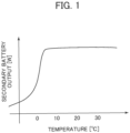
- FIG. 1 is a graph illustrating a temperature characteristic of a secondary battery output, the horizontal axis expresses the temperature [°C], and the vertical axis expresses the secondary battery output [W].
- the temperature characteristic that the secondary battery output sharply drops in the temperature lower than 10°C.
- most of lithium ion batteries used in the present battery systems 3, 6 correspond although there is slightly a difference according to the kind of the secondary battery.
- FIG. 2 is a graph illustrating a rectangular wave applied to a warm-up process, the horizontal axis expresses the time [sec], and the vertical axis expresses the charge and discharge current.
- the charge current is expressed in the positive direction
- the discharge current is expressed in the negative direction.
- the secondary battery is repeatedly charged and discharged by a rectangular wave, and the secondary battery is heated by Joule heat generated by the charge and discharge current and the internal resistance (battery resistance R).
- the warm-up process other than the above will be described later.
- FIG. 3 is a functional block diagram illustrating a summary of the battery system (the present battery system) 3 related to an embodiment of the present invention.
- a control flow for a power storage system 40 that is a control object of the present battery system 3.
- a railway vehicle mounting the power storage system 40 can also travel on a non-electrified section also by stored power of the power storage system 40.
- the power storage system 40 is configured to include plural secondary batteries (battery cells) series-parallel connected, and a control function for equalizing these respective voltage and charge and discharge current.
- a charge rate control unit (will be hereinafter referred to also as “control unit”) 61 has a function of controlling the timing and the charge rate (SOC) for charging electric power to the power storage system 40, and is configured to include the control unit 61, target charge rate data 62 of the battery, a temperature threshold 63 used for setting the target charge rate, and information of the clock time when the service of the railway vehicle mounting the power storage system 40 ends (service end information 64) .
- the service end information 64 is registered beforehand in the control unit 61 based on the train schedule and the like.
- a data table is formed in a memory included in the control unit 61. In the data table, there is stored at least information of the service end clock time of the railway vehicle and a charging equipment where the railway vehicle stops at the service end clock time or in advance by a predetermined time earlier.
- the control unit 61 is a control circuit formed of a computer and a hardware device executing software for example.
- the control unit 61 performs predetermined calculation based on information inputted from the outside (a charge rate detector 70, a temperature detector 71, and a time measuring instrument 80) and information retained in the inside (the target charge rate 62, the temperature threshold 63).
- the control unit 61 effects control so as to determine the charge rate of the power storage system 40 based on a result of the calculation described above.
- a cell controller and the like appropriately delivers information to the control unit 61 while measuring the battery cell constantly or periodically at a level subordinate to the control unit 61.
- the control unit 61 determines the charge rate with the first or the second value being employed for the target charge rate and the temperature threshold respectively based on the charge rate information acquired by the charge rate detector 70 and the temperature information acquired by the temperature detector 71. The detail of this control process will be described later. Also, with respect to the target charge rate 62 and the temperature threshold 63, at least either of a value registered in the control unit 61 beforehand and a value inputted to the control unit 61 from time to time only has to be applied, and it is also possible to combine the both.
- the setting value of the target charge rate 62 and the temperature threshold 63 employed for the control unit 61 can be selected for each period. As an example, it is possible that a value registered in an internal memory of the control unit 61 beforehand is used during a certain period, and that a value inputted from the outside of the control unit 61 is used in a period other than the said period.
- the target charge rate 62 two target charge rates of the first target charge rate and the second target charge rate are set.
- the first target charge rate is specified to be a threshold of the SOC value with which deterioration of the secondary battery hardly progresses.
- the second target charge rate the upper limit value of SOC with which a warm-up process at an assumed current value can be executed is set.
- the SOC value set for the second target charge rate is lower than an SOC value (SOC*) with which the remaining capacity of the battery possibly becomes zero during traveling of the railway vehicle
- SOC* is adopted for the value of the second target charge rate.
- the first target charge rate and the second target charge rate may be set to be a same value.
- two temperature thresholds of the first temperature threshold and the second temperature threshold are set. According to the circumstances, again, the first temperature threshold and the second temperature threshold may be set to be a same value.
- the service end information 64 at least includes a clock time when the railway vehicle ends the service, information on a charging equipment where the railway vehicle stops at a time point immediately before the end, and a clock time when the railway vehicle stops at the charging equipment.
- the charge rate detector 70 acquires information of the charging state of the power storage system 40 from the power storage system 40.
- the temperature detector 71 acquires temperature information of at least one of the temperature of the storage battery of one set or more provided within the power storage system 40 and the external air temperature. When plural temperature information have been measured, both of the maximum value and the minimum value out of them are applied.
- Temperature information of the power storage system 40 is referred to as "temperature information of the power storage system 40".
- the control unit 61 adopts the conveniently summarized temperature information for charge rate controlling so as to substitute the true temperature.
- a process for controlling the charge rate of the power storage system 40 by the control unit 61 will be hereinafter explained with exemplification and listing for respective concrete cases.
- the control unit 61 starts the control process in a charging equipment where the railway vehicle stops at a time point immediately before the service ends based on the service end information 64 of the railway vehicle.
- the control unit 61 acquires temperature information of the power storage system 40 from the temperature detector 71.
- the control unit 61 compares the temperature value acquired and the temperature threshold 63, and acquires charge rate information of the power storage system 40 of the charge rate detector 70. Based on the magnitude relation of the temperatures and the charge rate information obtained, the control unit 61 controls the charge rate of the power storage system 40 as described below.
- the control unit 61 controls the charge rate of the power storage system 40 as described below.
- the temperature value acquired from the temperature detector 71 has been measured by plural numbers, only the maximum value of them may be made the temperature information.
- the control unit 61 executes charging until the charge rate of the power storage system 40 reaches the target charge rate.
- the control unit 61 When the temperature value acquired from the temperature detector 71 (when plural values have been measured, the maximum value of them) is greater than the first temperature threshold and the charge rate acquired from the charge rate detector 71 is greater than the first target charge rate, the control unit 61 does not execute control of the power storage system 40.
- the control unit 61 executes charging until the charge rate of the power storage system 40 reaches the second target charge rate.
- the control unit 61 executes discharging until the charge rate of the power storage system 40 reaches the second target charge rate. Also, when the temperature and the charge rate of the power storage system 40 are not applicable to any of the above, the control unit 61 does not execute a control process for the power storage system 40.
- a secondary battery using spinel type lithium manganate (LiMn 2 O 4 ) for a positive electrode exemplifies the above.
- the first temperature threshold and the second temperature threshold are preferable to be 30°C or above and 30°C or below respectively, and are more preferable to be 35°C or above and 25°C or below respectively.
- the first target charge rate and the second target charge rate are preferable to be 70% or above and 70% or below respectively, and are more preferable to be 75% or above and 60% or below respectively. The reason for them will be given using FIG. 4 .
- FIG. 4 is a graph illustrating a temperature characteristic of battery deterioration used for setting the temperature threshold, the horizontal axis expresses the temperature [°C], and the vertical axis expresses the deterioration rate.
- the solid line of FIG. 4 expresses the temperature characteristic of the deterioration rate of the secondary battery, and such state can be confirmed that the deterioration rate of the secondary battery sharply increases as the temperature rises.
- the deterioration rate gradually increases around the point exceeding 20°C, and some measures come to be required when the temperature exceeds 40°C to 50°C.
- the single dot chain line of FIG. 4 is a tangent line on the higher temperature side of 40°C or above in the temperature characteristic illustrated by the solid line, and a tangent line on the lower temperature side of 10°C or below in the temperature characteristic illustrated by the solid line.
- the first temperature threshold is preferable to be equal to or greater than a value (30°C) where increase of the deterioration rate occurs, and the second temperature threshold is preferable to be equal to or lower than such value (30°C).
- the surface temperature of the secondary battery was measured as the information of the temperature, when the ambient temperature has been measured, it is preferable to use a value lower than the first and second temperature thresholds described above by approximately 5 to 10°C. The reason of it is that the surface temperature of the secondary battery becomes higher than the ambient temperature by approximately 5 to 10°C by emission of Joule heat in using the secondary battery.
- first target charge rate and second target charge rate are preferable to be 70% or above and 70% or below respectively, and are more preferable to be 75% or above and 60% or below respectively. The reason of it will be given using FIG. 5 .
- FIG. 5 is a graph illustrating charge rate dependability of battery deterioration used for setting the charge rate threshold, the horizontal axis expresses SOC [%], and the vertical axis expresses the deterioration rate.
- the solid line of FIG. 5 illustrates a result at 40°C (the first temperature threshold or above), and the broken line expresses a result at 10°C (the second temperature threshold or below).
- the charge rate of the secondary battery is too low, energy required for traveling of the railway vehicle cannot be supplemented, and therefore explanation of the object will be hereinafter a region where the charge rate is 50% or above.
- the secondary battery has very low charging rate dependability of the deterioration rate in the first temperature threshold or below.
- the charging rate dependability of the deterioration rate of the secondary battery increases in the first temperature threshold or above, and the deterioration rate changes largely in particular with approximately 30% and 70% of the charge rate as a boundary. Therefore, with respect to the secondary battery, it is preferable that the first target charge rate is made a range of SOC with a lower deterioration rate (70% or above of SOC), and the second target charge rate is also made a range of SOC with a lower deterioration rate (30% or below of SOC) in the first temperature threshold or above.
- the control unit 61 controls charging of the present battery system 3 so that the SOC of the secondary battery in the power storage system 40 becomes 70% or above.
- the present battery system 3 prevents the secondary battery in the power storage system 40 from being retained for a long time in a middle SOC band (the range of 40% to 70% of SOC, refer to the solid line of FIG. 5 ) under such high temperature as 40°C.
- the present battery system 3 can suppress accelerative progress of deterioration of the secondary battery.
- the temperature value acquired by the temperature detector 71 is 10°C and the SOC acquired by the charge rate detector 71 is 60%.
- the present battery system 3 does not control charging and discharging of the secondary battery.
- SOC dependability of the deterioration rate of the secondary battery is extremely low in such low temperature of lower than 10°C, as illustrated by the broken line of FIG. 5 , an effect of such control on deterioration of the secondary battery is extremely small.
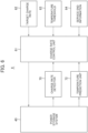
- FIG. 6 is a functional block diagram illustrating a summary of a battery system (this is also the present battery system) 6 related to a modification of the present battery system.
- the present battery system 6 of FIG. 6 is different in terms of employing a temperature prediction unit 72 instead of the temperature detector 71 in the present battery system 3 of FIG. 3 .
- a temperature pre-estimation unit 73 it is preferable, at timing when the service of a railway vehicle mounting the power storage system 40 ends, to have a function of acquiring a predicted value of the external air temperature of a time point when the railway vehicle is put in service next referring to meteorological forecast information and the like. For example, when the service of a railway vehicle ends in the evening of a certain date and time, the service is restarted next morning, a predicted value of the external air temperature of the next morning is acquired by the temperature pre-estimation unit 73.
- the control unit 61 starts a control process for charging the power storage system 40 in a charging equipment where the railway vehicle stops.
- the temperature prediction unit 72 has a function of predicting, in an instant before the service end of the railway vehicle, the external air temperature of a clock time of the next first train or slightly before the clock time.
- the control unit 61 acquires the predicted value from the temperature prediction unit 72.
- control unit 61 compares the temperature value acquired from the temperature prediction unit 72 and the temperature threshold 63, and acquires charge rate information of the power storage system 40 from the charge rate detector 70. Based on the magnitude relation and the charge rate information acquired, the control unit 61 controls the charge rate of the storage battery system as described below.
- the control unit 61 executes charging until the charge rate of the power storage system 40 reaches the target charge rate.
- the control unit 61 executes charging until the charge rate of the power storage system 40 reaches the second target charge rate.
- the control unit 61 executes discharging until the charge rate of the power storage system 40 reaches the second target charge rate.
- the control unit 61 does not execute a control process for the power storage system 40.
- the present battery system 6 controls the charge rate of the battery and can suppress deterioration by executing a series of calculation described above by the control unit 61. To the contrary, when it is predicted that the ambient temperature lowers, the present battery system 6 controls the power storage system 40 to a charge rate capable of executing a warm-up process efficiently, and can thereby suppress disruption of the train schedule of the railway vehicle.
- the mobility of a mobile body also can be secured by means of a secondary battery that is controlled by an appropriate SOC according to the external air temperature so as to achieve a long life and stabilization. That is to say, the present battery systems 3, 6 allow to utilize a secondary battery stably for a long time by controlling the charge rate of the secondary battery to a predetermined value according to the secondary battery temperature or the external air temperature and suppressing deterioration of the secondary battery under a high temperature environment. Also, the present battery systems 3, 6 can prevent delay of the train schedule of a railway vehicle even under a low temperature environment.
- the present invention is not to be limited to the embodiments described above, and various modifications are to be included.
- the present battery systems 3, 6 described above are those explained in detail for easy understanding of the invention, and are not necessarily to be limited to one including all configurations explained.
- a part of a configuration of an embodiment can be substituted by a configuration of other embodiments, and a configuration of an embodiment can be added with a configuration of other embodiments. Also, with respect to a part of a configuration of each embodiment, it is possible to effect addition, deletion, and substitution of other configurations.
- each configuration, function, processing unit, processing means, and the like expressed in each embodiment a part or all of them may be achieved by hardware by designing them and so on by an integrated circuit for example.
- each configuration, function, and the like described above may be achieved by software by that a CPU (Central Processing Unit) of a computer interprets and executes a program achieving each function.
- a CPU Central Processing Unit
- Information of a program, table, file, and the like achieving each function can be placed in a recording device such as a hard disk and an SSD (Solid State Drive) which are memories, or in a recording medium such as an IC card, SD card, and DVD.
- a recording device such as a hard disk and an SSD (Solid State Drive) which are memories, or in a recording medium such as an IC card, SD card, and DVD.
- control line and the information line those considered to be required for explanation are illustrated, and all control lines and information lines of a product are not necessarily shown. In practice, almost all configurations can be considered to be connected to each other.
- the power storage system 40 of high voltage and large capacity has become popular.
- This power storage system 40 has been widely used in order to save energy in a railway vehicle field also.
- a battery electric vehicle mounting the power storage system 40 of high voltage and large capacity has started to become popular.
- the battery electric vehicle not only travels using overhead contact line power obtained in an electrified section with an overhead contact line as a power source, but also can travel in a non-electrified section without an overhead contact line using the power storage system 40 as a power source. Therefore, the large power storage system 40 applied to a power source for power supply to the battery electric vehicle is required to be with high voltage and high power.
- Such power storage system 40 for high voltage and high power use is configured to connect plural battery cells in series and in parallel.
- An output of a secondary battery represented by a lithium ion battery has a temperature characteristic strongly depending on the external air temperature. With respect to the point, as described above using FIG. 1 , the temperature characteristic of causing sharp output drop particularly in a low temperature region from 10°C or below to 0°C becomes a usage problem.
- a cause of this temperature characteristic is considered to be a fact that the resistance of the secondary battery increases under a low temperature environment as an example.
- the power storage system 40 activates a self defensive control function, and thereby electrification of the secondary battery is stopped.
- electrification stop of the power storage system 40 not only discharging for driving a railway vehicle cannot be effected, but also charging of the power storage system 40 cannot be effected.
- a process of heating the secondary battery beforehand so that the secondary battery temperature becomes 0°C or above, preferably 10°C or above (warm-up process).
- the warm-up process in addition to a method of heating by a heater mounted on the power storage system 40 in advance, there can be cited a method that the secondary battery is repeatedly charged and discharged by a rectangular wave and the secondary battery is heated by Joule heat generated by the charge and discharge current and the internal resistance as described above using FIG. 2 , and so on.
- the ambient temperature in using a secondary battery also affects the deterioration characteristic of the secondary battery in addition to the output characteristic described above.
- a secondary battery has such characteristic that deterioration is liable to progress when it is used at a high temperature of 30°C or above or 45°C or above.
- the charge rate (SOC) can be cited.
- the charge rate SOC is also called a charge state, and is generally expressed as 0% for the fully discharged state on the specification and 100% for the fully charged state, but there is also an expression by an inverse number of it.
- SOC SOC
- the secondary battery there is specified in the specification a range of SOC where operation is assured as a safe product. To operate the secondary battery exceeding the upper and lower limits of this SOC range by the specification should be avoided since it becomes a cause of damaging the power storage system 40 and also becomes a cause for shortening the service life of the power storage system 40.
- a secondary battery using spinel type lithium manganate for a positive electrode active material has such characteristic that deterioration is liable to progress in a middle SOC band of approximately 30% to 60% under a high temperature environment. Therefore, in order to use a secondary battery stably for a long time, usage under a high temperature environment and in the middle SOC band should be avoided.
- V_OCV Open Circuit Voltage
- I expresses the charge current value.
- an upper and lower limit voltage allowing safe usage is set in the secondary battery, and it is common to limit the electrification amount when the secondary battery voltage deviates from this value. In such case, in order to efficiently execute warming up under a low temperature, it is required to increase the charge current value to increase emission of Joule heat.
- the present battery systems 3, 6 controls charging and discharging as described below.
- the control unit 61 controls charging and discharging based on a control rule described below.
- charging is executed so that the charge rate of the battery cell becomes higher than a predetermined value.
- charging is executed so that the charge rate of the battery becomes lower than the predetermined value.
- information of at least any one of the surface temperature of the battery cell and the ambient temperature which are easily measured as well as the estimate battery temperature by predetermine information and calculation formula may be used.
- the control unit 61 can acquire information of at least the ambient temperature, battery temperature, and charge rate, and has a function of appropriately controlling the charge rate based on the information to adapt the ambient temperature.
- an actual measured value or a predicted value is employed.
- a calculated value or a numerical value different for each season may be set.
- the temperature detector 71 acquires the actual measured value.
- the temperature prediction unit 72 forms the prediction value based on meteorological information and the like.
- the battery temperature may be acquired or calculated through a self-controller and the like from any one or more of the battery cells included in the power storage system 40.
- the charge rate also may be measured actually by the self-controller and the like from any one or more of the battery cells included in the power storage system 40.
- the control unit 61 applies a condition based on information acquired at timing described below, and controls charging.
- the timing is a time when a mobile body is immediately before the end of the service or the mobile body ends the service within an actual managing period. For example, in a railway where the service is managed by a train schedule, the timing can be considered to be immediately before the end of the service or the time of the end of the service of the last train in a managing period on a day-to-day basis.
- the end of the service is made an event that the battery electric vehicle stops at a charging equipment immediately before the end of service of the last train to execute charging and reaches a train depot and the like apart from the charging equipment.
- a charging equipment is attached to a train depot.
- the battery electric vehicle executes charging by power received from an overhead contact line without using a charging equipment. To all of these cases, the present battery systems 3, 6 can be applied.
- control unit 61 executes charging in accordance with a condition of charging control based on information acquired at the timing described above.
- the control unit 61 concretely sets a condition for charging control as described below to adapt to the ambient temperature.
- the present battery systems 3, 6 allow the secondary battery to be utilized stably for a long time by appropriately controlling the charge rate and the charge timing so as to adapt the ambient temperature. That is to say, when the control unit 61 executes charging in accordance with the condition of the charging control described above, the present battery systems 3, 6 are adapted to the ambient temperature, and therefore the life time of the plural battery cells configuring the power storage system 40 is extended and the resources energy efficiency can be improved.
- the mobility of a mobile body can be also ensured by means of a secondary battery that is controlled by an appropriate SOC according to the external air temperature.
- the temperature of the power storage system 40 is a temperature of at least one storage battery out of plural storage batteries, or a measured value of the same, or a predicted value of the same, and may be converted from the ambient temperature.
- the charge rate is a measured value or a calculated value of at least one storage battery out of plural storage batteries.
- Such present battery systems 3, 6 can be achieved easily by a simple configuration.
- the temperature characteristic of the battery is considered to be dependent on the temperature of the electrode, since it is hard to actually measure the temperature of the vicinity of the electrode in a non-destructive state, the temperature is estimated practically by a convenient alternative means.
- the charge rate control unit 61 can achieve an object of the present invention to enable both of extension of the service life of the battery and effective utilization of the battery output when the charge rate is controlled using the current temperature of a position where measurement is easy and the predicted air temperature by meteorological data.
- the present battery system 3, 6 instead of the internal temperature of the battery cell, the surface temperature of the battery cell and the ambient temperature may be substituted conveniently. To be more precise, an estimated temperature combiningly using various kind of correcting means may be employed. Also, by setting a condition of charging control described below based on the battery characteristic illustrated in FIG. 4 and FIG. 5 , the present battery system 3, 6 obtained a good result. It is preferable that the electric characteristic is applied based on a specification of the battery stored in a memory included in the control unit 61.
- the present battery system 3, 6 include a computer, and various kind of hardware devices and sensor groups configuring an electric circuit. Also, a major portion of functions of the control unit 61 is achieved by that the CPU of the computer executes a program stored in the memory.
- the computer may be one-chip microcomputer or a personal computer, and a part of a computer in use for another usage may be shared.
- the control unit 61 forms a data table in a memory included in the control unit 61.
- the data table there is stored at least information of a service end clock time of a mobile body and a charging equipment where the mobile body stops at the service end clock time or in advance by a predetermined time earlier.
- the control unit 61 allows the power storage system 40 to start charging.
- the mobile body is a railway vehicle, a battery electric vehicle is suitable, and a hybrid electric vehicle is also applicable.
- the control unit 61 allows the power storage system 40 to start charging at a charging equipment where the railway vehicle stops at a service end clock time or in advance by a predetermined time earlier and with the charge rate adapted to the ambient temperature.
- the railway vehicle can travel a section without an overhead contact line with a high energy efficiency since it is charged excellently at the time of starting the first service.
- a battery cell secures a good result when spinel type lithium manganate is used for a positive electrode active material.
Landscapes
- Chemical & Material Sciences (AREA)
- Engineering & Computer Science (AREA)
- Chemical Kinetics & Catalysis (AREA)
- Electrochemistry (AREA)
- General Chemical & Material Sciences (AREA)
- Manufacturing & Machinery (AREA)
- Power Engineering (AREA)
- Materials Engineering (AREA)
- Aviation & Aerospace Engineering (AREA)
- Microelectronics & Electronic Packaging (AREA)
- Inorganic Chemistry (AREA)
- Charge And Discharge Circuits For Batteries Or The Like (AREA)
- Secondary Cells (AREA)
Abstract
Description
- The present invention relates to a battery system and a method of controlling the same.
- With respect to a power storage system including a secondary battery, controlling with appropriate temperature and charge rate (SOC: State of Charge) is important for stably securing the output characteristic of the secondary battery and suppressing battery deterioration of the secondary battery. For example, in Patent Literature 1, there is disclosed a storage battery controller acquiring temperature information and charge rate information of a secondary battery, and switching the secondary battery to a discharge state when the charge rate of the secondary battery is a specific threshold or above and the second battery temperature is a specific threshold temperature or below based on the information.
- Patent Literature 1:
Japanese Unexamined Patent Application Publication No. 2019-4565 - According to the storage battery controller of Patent Literature 1, since such event can be suppressed that the secondary battery under a low temperature environment is cooled and the second battery temperature drops, there is an effect of suppressing deterioration of the output characteristic of the secondary battery. However, in Patent Literature 1, there is no mention on a controlling technology on the charge rate of the secondary battery and a service method under a high temperature environment from the viewpoint of suppressing deterioration.
- The present invention has been achieved in view of the problem described above, and its object is to provide a battery system enabling stable long-term utilization of a secondary battery by properly controlling SOC of the secondary battery according to the external air temperature and thereby enabling to secure mobility of a mobile body. Solution to Problem
- The present invention solving the problem described above is a battery system including: a power storage system that has a plurality of battery cells, and is mounted on a mobile body; and a charge rate control unit that controls the charge rate of the power storage system, in which the charge rate control unit controls, on the basis of the temperature of the power storage system and the charge rate of the power storage system, charging of the power storage system from charging equipment when the operation of the mobile body is ended, and sets charging control conditions such that the charge rate of the power storage system is greater than a first charge rate threshold in a state in which the temperature of the power storage system is greater than a first temperature threshold, and the charge rate of the power storage system is lower than a second charge rate threshold, which is equal to or lower than the first charge rate threshold, in a state in which the temperature of the power storage system is lower than a second temperature threshold which is equal to or lower than the first temperature threshold.
- According to the present invention, it is possible to provide a battery system enabling stable long-term utilization of a secondary battery by properly controlling SOC of the secondary battery according to the external air temperature and thereby enabling to secure mobility of a mobile body.
-
- [
FIG. 1] FIG. 1 is a graph illustrating a temperature characteristic of a secondary battery output. - [
FIG. 2] FIG. 2 is a graph illustrating a rectangular wave applied to a warm-up process. - [
FIG. 3] FIG. 3 is a functional block diagram illustrating a summary of a battery system related to an embodiment of the present invention (will be hereinafter referred to as "the present battery system"). - [
FIG. 4] FIG. 4 is a graph illustrating a temperature characteristic (temperature dependability) of battery deterioration used for setting the temperature threshold. - [
FIG. 5] FIG. 5 is a graph illustrating charge rate dependability of battery deterioration used for setting the charge rate threshold. - [
FIG. 6] FIG. 6 is a functional block diagram illustrating a summary of a battery system related to a modification of the present invention (this also will be referred to as "the present battery system"). - Embodiments of the present invention will be hereinafter described in detail using the drawings and the like. Explanations described hereinafter express concrete examples of the content of the present invention, the present invention is not to be limited to these explanations, and various alterations and modifications by a person with an ordinal skill in the art are possible within a range of the technical thought disclosed in the present description. Further, in all drawings for explaining the present invention, those having a same function will be marked with a same reference sign, and repeated explanation for the same will be omitted. Furthermore, a second battery (storage battery) may possibly be hereinafter abbreviated simply as "battery".
-
FIG. 1 is a graph illustrating a temperature characteristic of a secondary battery output, the horizontal axis expresses the temperature [°C], and the vertical axis expresses the secondary battery output [W]. As illustrated inFIG. 1 , there is known such temperature characteristic that the secondary battery output sharply drops in the temperature lower than 10°C. To this temperature characteristic, most of lithium ion batteries used in thepresent battery systems 3, 6 (FIG. 3 ,FIG. 6 ) correspond although there is slightly a difference according to the kind of the secondary battery. -
FIG. 2 is a graph illustrating a rectangular wave applied to a warm-up process, the horizontal axis expresses the time [sec], and the vertical axis expresses the charge and discharge current. In the graph ofFIG. 2 , the charge current is expressed in the positive direction, and the discharge current is expressed in the negative direction. In the warm-up process, although power consumption of a certain degree might be inevitable, in order to efficiently effect heat emission and heat retention of the battery with the minimum power consumption, as illustrated inFIG. 2 , the secondary battery is repeatedly charged and discharged by a rectangular wave, and the secondary battery is heated by Joule heat generated by the charge and discharge current and the internal resistance (battery resistance R). A concrete example of the warm-up process other than the above will be described later. -
FIG. 3 is a functional block diagram illustrating a summary of the battery system (the present battery system) 3 related to an embodiment of the present invention. InFIG. 3 , there will also be expressed a control flow for apower storage system 40 that is a control object of thepresent battery system 3. A railway vehicle mounting thepower storage system 40 can also travel on a non-electrified section also by stored power of thepower storage system 40. Thepower storage system 40 is configured to include plural secondary batteries (battery cells) series-parallel connected, and a control function for equalizing these respective voltage and charge and discharge current. - A charge rate control unit (will be hereinafter referred to also as "control unit") 61 has a function of controlling the timing and the charge rate (SOC) for charging electric power to the
power storage system 40, and is configured to include thecontrol unit 61, targetcharge rate data 62 of the battery, atemperature threshold 63 used for setting the target charge rate, and information of the clock time when the service of the railway vehicle mounting thepower storage system 40 ends (service end information 64) . - The
service end information 64 is registered beforehand in thecontrol unit 61 based on the train schedule and the like. A data table is formed in a memory included in thecontrol unit 61. In the data table, there is stored at least information of the service end clock time of the railway vehicle and a charging equipment where the railway vehicle stops at the service end clock time or in advance by a predetermined time earlier. - The
control unit 61 is a control circuit formed of a computer and a hardware device executing software for example. Thecontrol unit 61 performs predetermined calculation based on information inputted from the outside (acharge rate detector 70, atemperature detector 71, and a time measuring instrument 80) and information retained in the inside (thetarget charge rate 62, the temperature threshold 63). Thecontrol unit 61 effects control so as to determine the charge rate of thepower storage system 40 based on a result of the calculation described above. Such mode is also possible alternatively that a cell controller and the like appropriately delivers information to thecontrol unit 61 while measuring the battery cell constantly or periodically at a level subordinate to thecontrol unit 61. - The
control unit 61 determines the charge rate with the first or the second value being employed for the target charge rate and the temperature threshold respectively based on the charge rate information acquired by thecharge rate detector 70 and the temperature information acquired by thetemperature detector 71. The detail of this control process will be described later. Also, with respect to thetarget charge rate 62 and thetemperature threshold 63, at least either of a value registered in thecontrol unit 61 beforehand and a value inputted to thecontrol unit 61 from time to time only has to be applied, and it is also possible to combine the both. - The setting value of the
target charge rate 62 and thetemperature threshold 63 employed for thecontrol unit 61 can be selected for each period. As an example, it is possible that a value registered in an internal memory of thecontrol unit 61 beforehand is used during a certain period, and that a value inputted from the outside of thecontrol unit 61 is used in a period other than the said period. - With respect to the
target charge rate 62, two target charge rates of the first target charge rate and the second target charge rate are set. The first target charge rate is specified to be a threshold of the SOC value with which deterioration of the secondary battery hardly progresses. With respect to the second target charge rate, the upper limit value of SOC with which a warm-up process at an assumed current value can be executed is set. - However, when the SOC value set for the second target charge rate is lower than an SOC value (SOC*) with which the remaining capacity of the battery possibly becomes zero during traveling of the railway vehicle, SOC* is adopted for the value of the second target charge rate. According to the circumstances, the first target charge rate and the second target charge rate may be set to be a same value. In a similar manner, with respect to the
temperature threshold 63 also, two temperature thresholds of the first temperature threshold and the second temperature threshold are set. According to the circumstances, again, the first temperature threshold and the second temperature threshold may be set to be a same value. - The
service end information 64 at least includes a clock time when the railway vehicle ends the service, information on a charging equipment where the railway vehicle stops at a time point immediately before the end, and a clock time when the railway vehicle stops at the charging equipment. Thecharge rate detector 70 acquires information of the charging state of thepower storage system 40 from thepower storage system 40. - As the temperature information of the
power storage system 40, thetemperature detector 71 acquires temperature information of at least one of the temperature of the storage battery of one set or more provided within thepower storage system 40 and the external air temperature. When plural temperature information have been measured, both of the maximum value and the minimum value out of them are applied. - Temperature information obtained by summarizing easily-acquired numerical values with an appropriate standard in an easy-to-use and convenient manner as described above is referred to as "temperature information of the
power storage system 40". Although the temperature characteristic of thepower storage system 40 is determined by the temperature of the internal electrode positioned in a deeper portion of the built-in battery cell, since it is hard to measure a true temperature, thecontrol unit 61 adopts the conveniently summarized temperature information for charge rate controlling so as to substitute the true temperature. - A process for controlling the charge rate of the
power storage system 40 by thecontrol unit 61 will be hereinafter explained with exemplification and listing for respective concrete cases. Thecontrol unit 61 starts the control process in a charging equipment where the railway vehicle stops at a time point immediately before the service ends based on theservice end information 64 of the railway vehicle. First, thecontrol unit 61 acquires temperature information of thepower storage system 40 from thetemperature detector 71. - At this time, the
control unit 61 compares the temperature value acquired and thetemperature threshold 63, and acquires charge rate information of thepower storage system 40 of thecharge rate detector 70. Based on the magnitude relation of the temperatures and the charge rate information obtained, thecontrol unit 61 controls the charge rate of thepower storage system 40 as described below. Here, when the temperature value acquired from thetemperature detector 71 has been measured by plural numbers, only the maximum value of them may be made the temperature information. - When the temperature value acquired from the temperature detector 71 (when plural values have been measured, the maximum value of them) is greater than the first temperature threshold and the charge rate acquired from the
charge rate detector 71 is lower than the first target charge rate, thecontrol unit 61 executes charging until the charge rate of thepower storage system 40 reaches the target charge rate. - When the temperature value acquired from the temperature detector 71 (when plural values have been measured, the maximum value of them) is greater than the first temperature threshold and the charge rate acquired from the
charge rate detector 71 is greater than the first target charge rate, thecontrol unit 61 does not execute control of thepower storage system 40. - When the temperature value acquired from the temperature detector 71 (when plural values have been measured, the minimum value of them) is lower than the second temperature threshold and the charge rate acquired from the
charge rate detector 71 is lower than the second target charge rate, thecontrol unit 61 executes charging until the charge rate of thepower storage system 40 reaches the second target charge rate. - When the temperature value acquired from the temperature detector 71 (when plural values have been measured, the minimum value of them) is lower than the second temperature threshold and the charge rate acquired from the
charge rate detector 71 is greater than the second target charge rate, thecontrol unit 61 executes discharging until the charge rate of thepower storage system 40 reaches the second target charge rate. Also, when the temperature and the charge rate of thepower storage system 40 are not applicable to any of the above, thecontrol unit 61 does not execute a control process for thepower storage system 40. - By executing the charge rate control described above, both of suppression of deterioration of the storage battery under a high temperature environment and high efficiency of the warm-up process under a low temperature environment can be achieved. A secondary battery using spinel type lithium manganate (LiMn2O4) for a positive electrode exemplifies the above.
- Also, a case where the surface temperature and the charge rate of a secondary battery have been measured will be hereinafter studied. In this case, the first temperature threshold and the second temperature threshold are preferable to be 30°C or above and 30°C or below respectively, and are more preferable to be 35°C or above and 25°C or below respectively. Also, the first target charge rate and the second target charge rate are preferable to be 70% or above and 70% or below respectively, and are more preferable to be 75% or above and 60% or below respectively. The reason for them will be given using
FIG. 4 . -
FIG. 4 is a graph illustrating a temperature characteristic of battery deterioration used for setting the temperature threshold, the horizontal axis expresses the temperature [°C], and the vertical axis expresses the deterioration rate. The solid line ofFIG. 4 expresses the temperature characteristic of the deterioration rate of the secondary battery, and such state can be confirmed that the deterioration rate of the secondary battery sharply increases as the temperature rises. As illustrated inFIG. 4 , the deterioration rate gradually increases around the point exceeding 20°C, and some measures come to be required when the temperature exceeds 40°C to 50°C. - Also, the single dot chain line of
FIG. 4 is a tangent line on the higher temperature side of 40°C or above in the temperature characteristic illustrated by the solid line, and a tangent line on the lower temperature side of 10°C or below in the temperature characteristic illustrated by the solid line. Thus, around 30°C where the intersection point of the tangent line on the lower temperature side and the tangent line on the higher temperature side is located, the deterioration rate sharply increases. Therefore, the first temperature threshold is preferable to be equal to or greater than a value (30°C) where increase of the deterioration rate occurs, and the second temperature threshold is preferable to be equal to or lower than such value (30°C). - Further, although such case was exemplified here that the surface temperature of the secondary battery was measured as the information of the temperature, when the ambient temperature has been measured, it is preferable to use a value lower than the first and second temperature thresholds described above by approximately 5 to 10°C. The reason of it is that the surface temperature of the secondary battery becomes higher than the ambient temperature by approximately 5 to 10°C by emission of Joule heat in using the secondary battery.
- Next, a method for determining the value of the first and second target charge rates will be shown. These first target charge rate and second target charge rate are preferable to be 70% or above and 70% or below respectively, and are more preferable to be 75% or above and 60% or below respectively. The reason of it will be given using
FIG. 5 . -
FIG. 5 is a graph illustrating charge rate dependability of battery deterioration used for setting the charge rate threshold, the horizontal axis expresses SOC [%], and the vertical axis expresses the deterioration rate. The solid line ofFIG. 5 illustrates a result at 40°C (the first temperature threshold or above), and the broken line expresses a result at 10°C (the second temperature threshold or below). Also, when the charge rate of the secondary battery is too low, energy required for traveling of the railway vehicle cannot be supplemented, and therefore explanation of the object will be hereinafter a region where the charge rate is 50% or above. - As illustrated by the broken line of
FIG. 5 , the secondary battery has very low charging rate dependability of the deterioration rate in the first temperature threshold or below. However, as illustrated by the solid line ofFIG. 5 , the charging rate dependability of the deterioration rate of the secondary battery increases in the first temperature threshold or above, and the deterioration rate changes largely in particular with approximately 30% and 70% of the charge rate as a boundary. Therefore, with respect to the secondary battery, it is preferable that the first target charge rate is made a range of SOC with a lower deterioration rate (70% or above of SOC), and the second target charge rate is also made a range of SOC with a lower deterioration rate (30% or below of SOC) in the first temperature threshold or above. - With respect to the
present battery system 3, explanation will be made how deterioration of the secondary battery is suppressed when the first and second temperature thresholds and the first and second charge rates set as described above are used. As an example, first, such case is studied that the temperature value acquired by thetemperature detector 71 is 40°C, and SOC acquired from thecharge rate detector 71 is 60%. - Since the temperature values described above are the first temperature threshold or below and the SOC are the first target charge rate or below, the
control unit 61 controls charging of thepresent battery system 3 so that the SOC of the secondary battery in thepower storage system 40 becomes 70% or above. Thus, thepresent battery system 3 prevents the secondary battery in thepower storage system 40 from being retained for a long time in a middle SOC band (the range of 40% to 70% of SOC, refer to the solid line ofFIG. 5 ) under such high temperature as 40°C. As a result, thepresent battery system 3 can suppress accelerative progress of deterioration of the secondary battery. - As another example, such case is explained that the temperature value acquired by the
temperature detector 71 is 10°C and the SOC acquired by thecharge rate detector 71 is 60%. At this time, since the temperature value is the second temperature threshold or below and the SOC is the second target charge rate or below, thepresent battery system 3 does not control charging and discharging of the secondary battery. The reason of it is that, since SOC dependability of the deterioration rate of the secondary battery is extremely low in such low temperature of lower than 10°C, as illustrated by the broken line ofFIG. 5 , an effect of such control on deterioration of the secondary battery is extremely small. - On the other hand, under such low temperature as 10°C, it is desirable to execute a warm-up process for the secondary battery before using the secondary battery for traveling of a railway vehicle. At this time, according to the
present battery system 3, since sooner warm-up process can be started for thepower storage system 40 when the SOC value is one enabling a warm-up process (the range of 50% to 70% of SOC), the time required for the warm-up process before the start of the vehicle service can be minimized. -
FIG. 6 is a functional block diagram illustrating a summary of a battery system (this is also the present battery system) 6 related to a modification of the present battery system. Thepresent battery system 6 ofFIG. 6 is different in terms of employing atemperature prediction unit 72 instead of thetemperature detector 71 in thepresent battery system 3 ofFIG. 3 . - In a temperature pre-estimation unit 73, it is preferable, at timing when the service of a railway vehicle mounting the
power storage system 40 ends, to have a function of acquiring a predicted value of the external air temperature of a time point when the railway vehicle is put in service next referring to meteorological forecast information and the like. For example, when the service of a railway vehicle ends in the evening of a certain date and time, the service is restarted next morning, a predicted value of the external air temperature of the next morning is acquired by the temperature pre-estimation unit 73. - An operation of the
control unit 61 in thepresent battery system 6 with respect to the information acquired by thetemperature prediction unit 72 will be hereinafter explained. It is common that a railway vehicle stops at a charging equipment at a time point immediately before the end of the service based on theservice end information 64 namely a train schedule. Thecontrol unit 61 starts a control process for charging thepower storage system 40 in a charging equipment where the railway vehicle stops. It is preferable that thetemperature prediction unit 72 has a function of predicting, in an instant before the service end of the railway vehicle, the external air temperature of a clock time of the next first train or slightly before the clock time. Thecontrol unit 61 acquires the predicted value from thetemperature prediction unit 72. - At this time, the
control unit 61 compares the temperature value acquired from thetemperature prediction unit 72 and thetemperature threshold 63, and acquires charge rate information of thepower storage system 40 from thecharge rate detector 70. Based on the magnitude relation and the charge rate information acquired, thecontrol unit 61 controls the charge rate of the storage battery system as described below. - When the temperature value acquired from the
temperature prediction unit 72 is higher than the first temperature threshold and the charge rate acquired from thecharge rate detector 71 is lower than the first target charge rate, thecontrol unit 61 executes charging until the charge rate of thepower storage system 40 reaches the target charge rate. - When the temperature value acquired from the
temperature prediction unit 72 is lower than the second temperature threshold and the charge rate acquired from thecharge rate detector 71 is lower than the second target charge rate, thecontrol unit 61 executes charging until the charge rate of thepower storage system 40 reaches the second target charge rate. - When the temperature value acquired from the
temperature prediction unit 72 is lower than the second temperature threshold and the charge rate acquired from thecharge rate detector 71 is higher than the second target charge rate, thecontrol unit 61 executes discharging until the charge rate of thepower storage system 40 reaches the second target charge rate. When the temperature and the charge rate of thepower storage system 40 are not applicable to any of the above, thecontrol unit 61 does not execute a control process for thepower storage system 40. - When it is predicted that the ambient temperature rises, the
present battery system 6 controls the charge rate of the battery and can suppress deterioration by executing a series of calculation described above by thecontrol unit 61. To the contrary, when it is predicted that the ambient temperature lowers, thepresent battery system 6 controls thepower storage system 40 to a charge rate capable of executing a warm-up process efficiently, and can thereby suppress disruption of the train schedule of the railway vehicle. - From the above, according to the
present battery systems present battery systems present battery systems - Also, the present invention is not to be limited to the embodiments described above, and various modifications are to be included. For example, the
present battery systems - Also, a part of a configuration of an embodiment can be substituted by a configuration of other embodiments, and a configuration of an embodiment can be added with a configuration of other embodiments. Also, with respect to a part of a configuration of each embodiment, it is possible to effect addition, deletion, and substitution of other configurations.
- Also, with respect to the configuration, function, processing unit, processing means, and the like expressed in each embodiment, a part or all of them may be achieved by hardware by designing them and so on by an integrated circuit for example. Also, each configuration, function, and the like described above may be achieved by software by that a CPU (Central Processing Unit) of a computer interprets and executes a program achieving each function.
- Information of a program, table, file, and the like achieving each function can be placed in a recording device such as a hard disk and an SSD (Solid State Drive) which are memories, or in a recording medium such as an IC card, SD card, and DVD. Also, with respect to the control line and the information line, those considered to be required for explanation are illustrated, and all control lines and information lines of a product are not necessarily shown. In practice, almost all configurations can be considered to be connected to each other.
- In recent years, reduction of the exhaust amount of carbon dioxide has been demanded in order to prevent global warming. For example, with respect to an automobile using a gasoline engine which is one of a large discharge source of carbon dioxide, substitution to a hybrid electric car, an electric car, and the like is proceeding. As a storage battery (secondary battery) suitable to the above and capable of charging and discharging, there exist a lithium ion secondary battery, nickel-hydrogen battery, lead battery, electric double layer capacitor, and the like. Among them, the
power storage system 40 including plural battery cells with high output density represented by a lithium ion battery is employed widely for industrial use. - In recent years, the
power storage system 40 of high voltage and large capacity has become popular. Thispower storage system 40 has been widely used in order to save energy in a railway vehicle field also. Particularly, with an object of reducing the environmental load of a railway vehicle traveling a non-electrified section without an overhead contact line, a battery electric vehicle mounting thepower storage system 40 of high voltage and large capacity has started to become popular. - The battery electric vehicle not only travels using overhead contact line power obtained in an electrified section with an overhead contact line as a power source, but also can travel in a non-electrified section without an overhead contact line using the
power storage system 40 as a power source. Therefore, the largepower storage system 40 applied to a power source for power supply to the battery electric vehicle is required to be with high voltage and high power. Suchpower storage system 40 for high voltage and high power use is configured to connect plural battery cells in series and in parallel. - For each battery cell configured as described above, standardized lithium ion batteries are heavily used. An output of a secondary battery represented by a lithium ion battery has a temperature characteristic strongly depending on the external air temperature. With respect to the point, as described above using
FIG. 1 , the temperature characteristic of causing sharp output drop particularly in a low temperature region from 10°C or below to 0°C becomes a usage problem. - A cause of this temperature characteristic is considered to be a fact that the resistance of the secondary battery increases under a low temperature environment as an example. As a phenomenon that the voltage of the secondary battery deviates an upper and lower limit range set in a specification by this temperature characteristic, overvoltage at the time of electrification rises. To cope with this phenomenon, the
power storage system 40 activates a self defensive control function, and thereby electrification of the secondary battery is stopped. By electrification stop of thepower storage system 40, not only discharging for driving a railway vehicle cannot be effected, but also charging of thepower storage system 40 cannot be effected. - Therefore, when a secondary battery is to be used under a low temperature environment, there is required a process of heating the secondary battery beforehand so that the secondary battery temperature becomes 0°C or above, preferably 10°C or above (warm-up process). As such the warm-up process, in addition to a method of heating by a heater mounted on the
power storage system 40 in advance, there can be cited a method that the secondary battery is repeatedly charged and discharged by a rectangular wave and the secondary battery is heated by Joule heat generated by the charge and discharge current and the internal resistance as described above usingFIG. 2 , and so on. - The ambient temperature in using a secondary battery also affects the deterioration characteristic of the secondary battery in addition to the output characteristic described above. In general, a secondary battery has such characteristic that deterioration is liable to progress when it is used at a high temperature of 30°C or above or 45°C or above. Other than the temperature, as one of the factors affecting deterioration of the secondary battery, the charge rate (SOC) can be cited.
- The charge rate SOC is also called a charge state, and is generally expressed as 0% for the fully discharged state on the specification and 100% for the fully charged state, but there is also an expression by an inverse number of it. In general, with respect to the secondary battery, there is specified in the specification a range of SOC where operation is assured as a safe product. To operate the secondary battery exceeding the upper and lower limits of this SOC range by the specification should be avoided since it becomes a cause of damaging the
power storage system 40 and also becomes a cause for shortening the service life of thepower storage system 40. - Also, it is widely known that deterioration acceleratedly progresses in a specific SOC band even when the charge rate is within the specification SOC range, as the battery capacity reduces, the internal resistance increases, and an output fluctuates exceeding an allowable range. It is known that the SCO band where deterioration of a secondary battery is liable to progress depends on active material used for an electrode.
- For example, a secondary battery using spinel type lithium manganate for a positive electrode active material has such characteristic that deterioration is liable to progress in a middle SOC band of approximately 30% to 60% under a high temperature environment. Therefore, in order to use a secondary battery stably for a long time, usage under a high temperature environment and in the middle SOC band should be avoided.
- When deterioration of a secondary battery progresses, drop of the battery capacity and increase of the internal resistance occur. Therefore, accompanying deterioration of a battery, a power amount and an output of the
power storage system 40 gradually drop, and thepower storage system 40 eventually becomes unusable. In addition, when an output of thepower storage system 40 drops during traveling of a railway vehicle, stoppage of the vehicle is incurred. - In order to prevent such problem, it is required to appropriately replace the
power storage system 40 where deterioration of a secondary battery progressed. However, a large amount of secondary batteries is used by thepower storage system 40 for a battery electric vehicle to adapt traveling of the vehicle, and the proportion of the cost of the secondary battery in the overall vehicle system is high. Therefore, the control technology for suppressing deterioration of the secondary battery is emphasized also from a viewpoint of suppressing the running cost of the vehicle system. - As an example of the measures for suppressing progress of deterioration, it is considered to be effective to maintain the charge rate of the secondary battery to a low SOC or a high SOC avoiding a middle SOC band. However, when the
power storage system 40 is to be used in a low SOC (low charge rate), depending on a traveling section of the railway vehicle, there is a risk that the capacity of the secondary battery is consumed entirely during the travel. Also, when thepower storage system 40 is to be used in a high SOC keeping the train schedule appropriately, there is a case that the warm-up process of the secondary battery under a low temperature becomes hard. The reason of it will be described below. Since the battery resistance R increases under a low temperature environment as described above, the battery voltage V at the time of charging is approximatively expressed as described below.
- Here, V_OCV (Open Circuit Voltage) is an open circuit voltage (battery voltage at the time of non-electrification), and I expresses the charge current value. In general, an upper and lower limit voltage allowing safe usage is set in the secondary battery, and it is common to limit the electrification amount when the secondary battery voltage deviates from this value. In such case, in order to efficiently execute warming up under a low temperature, it is required to increase the charge current value to increase emission of Joule heat.
- Therefore, in order that the secondary battery voltage does not deviate from the upper limit value of the voltage while increasing the charge current value, it is required to reduce the open circuit voltage V_OCV in the expression (1) described above. If this fact corresponds to an operation for maintaining the charge rate (SOC) of the secondary battery to be low, the warm-up process possibly becomes hard when the
power storage system 40 is used at a high SOC. - When a current value capable to be applied to a secondary battery becomes small, the time required for warming up also becomes long which becomes a cause for delaying the train schedule of the railway vehicle. Further, although it is also possible to warm-up a secondary battery by discharging, in this case, such process is required to execute discharging to warm-up the secondary battery and to charge the secondary battery thereafter in preparation for vehicle travel, a long time is required until completion of a series of processes, and there is therefore a risk of incurring delay of the train schedule also in this case.
- Therefore, with respect to the
power storage system 40 mounted on a railway vehicle, thepresent battery systems power storage system 40, the charge rate of any one or more battery cell out of plural battery cells included in thepower storage system 40 and the temperature of any battery cell in a similar manner are measured constantly or periodically by a self-controller and the like. Also, the ambient temperature of thepower storage system 40 is also measured constantly or periodically to be acquirable by thecontrol unit 61. - Next, when the service of the vehicle ends, the
control unit 61 controls charging and discharging based on a control rule described below. When the measured temperature is higher than a predetermined temperature, charging is executed so that the charge rate of the battery cell becomes higher than a predetermined value. To the contrary, when the measured temperature is lower than the predetermined temperature, charging is executed so that the charge rate of the battery becomes lower than the predetermined value. Also, with respect to the temperature information applied as this control rule, information of at least any one of the surface temperature of the battery cell and the ambient temperature which are easily measured as well as the estimate battery temperature by predetermine information and calculation formula may be used. - With respect to the
present battery systems - [1] The
present battery systems FIG. 3 andFIG. 6 include thepower storage system 40 that has plural battery cells and thecontrol unit 61 that can control at least a charge rate and timing for charging with respect to thepower storage system 40, and are applied to a mobile body. Thepower storage system 40 has a self-controller that manages a state of each of the plural battery cells or a function similar to that of the self-controller. - The
control unit 61 can acquire information of at least the ambient temperature, battery temperature, and charge rate, and has a function of appropriately controlling the charge rate based on the information to adapt the ambient temperature. With respect to the ambient temperature, an actual measured value or a predicted value is employed. With respect to the predicted value, a calculated value or a numerical value different for each season may be set. With respect to thepresent battery system 3 ofFIG. 3 , thetemperature detector 71 acquires the actual measured value. With respect to thepresent battery system 6 ofFIG. 6 , thetemperature prediction unit 72 forms the prediction value based on meteorological information and the like. The battery temperature may be acquired or calculated through a self-controller and the like from any one or more of the battery cells included in thepower storage system 40. The charge rate also may be measured actually by the self-controller and the like from any one or more of the battery cells included in thepower storage system 40. - The
control unit 61 applies a condition based on information acquired at timing described below, and controls charging. The timing is a time when a mobile body is immediately before the end of the service or the mobile body ends the service within an actual managing period. For example, in a railway where the service is managed by a train schedule, the timing can be considered to be immediately before the end of the service or the time of the end of the service of the last train in a managing period on a day-to-day basis. - Also, with respect to the railway vehicle namely the battery electric vehicle, there is a case that the end of the service is made an event that the battery electric vehicle stops at a charging equipment immediately before the end of service of the last train to execute charging and reaches a train depot and the like apart from the charging equipment. On the other hand, there is also a case that a charging equipment is attached to a train depot. There is also a case that the battery electric vehicle executes charging by power received from an overhead contact line without using a charging equipment. To all of these cases, the
present battery systems - With respect to the
present battery systems control unit 61 executes charging in accordance with a condition of charging control based on information acquired at the timing described above. Thecontrol unit 61 concretely sets a condition for charging control as described below to adapt to the ambient temperature. - When the battery temperature is higher than the predetermined first temperature threshold, charging is executed so that the charge rate becomes higher than the first charge rate threshold.
- When the ambient temperature is lower than the predetermined second temperature threshold, charging is executed so that the charge rate becomes lower than the second charge rate threshold.
- The
present battery systems control unit 61 executes charging in accordance with the condition of the charging control described above, thepresent battery systems power storage system 40 is extended and the resources energy efficiency can be improved. In addition, according to thepresent battery systems - [2] In [1] described above, the temperature of the
power storage system 40 is a temperature of at least one storage battery out of plural storage batteries, or a measured value of the same, or a predicted value of the same, and may be converted from the ambient temperature. Also, the charge rate is a measured value or a calculated value of at least one storage battery out of plural storage batteries. Suchpresent battery systems rate control unit 61 can achieve an object of the present invention to enable both of extension of the service life of the battery and effective utilization of the battery output when the charge rate is controlled using the current temperature of a position where measurement is easy and the predicted air temperature by meteorological data. - [3] In [1] described above, with respect to the
present battery system FIG. 4 and FIG. 5 , thepresent battery system control unit 61. - When the battery temperature is to be applied to information of the temperature, the first temperature threshold is set to 30°C or above, and the second temperature threshold is set to 30°C or below.
- When the ambient temperature is to be applied to information of the temperature, the first temperature threshold is set to 25°C or above, and the second temperature threshold is set to 25°C or below.
- [4] In the
present battery system control unit 61 obtained a good result adapting to the ambient temperature. The condition of charging control described below also may be applied based on the specification of the battery stored in a memory included in thecontrol unit 61. That is to say, the above is setting based on the battery characteristic illustrated inFIG. 4 and FIG. 5 . - The first charge rate threshold is set to 70% or above of the charge rate, and the second charge rate threshold is set to 70% or below of the charge rate.
- [5] In the
present battery system control unit 61 obtained a good result adapting to the ambient temperature. The condition setting of charging control described below also may be applied based on the specification of the battery stored in a memory included in thecontrol unit 61. That is to say, the above is setting based on the battery characteristic illustrated inFIG. 4 and FIG. 5 . - When the battery temperature is to be applied to information of the temperature, the first temperature threshold is set to 35°C or above, and the second temperature threshold is set to 20°C or below.
- When the ambient temperature is to be applied to information of the temperature, the first temperature threshold is set to 30°C or above, and the second temperature threshold is set to 10°C or below.
- [6] In the
present battery system control unit 61 obtained a good result adapting to the ambient temperature. The condition setting of charging control described below also may be applied based on the specification of the battery stored in a memory included in thecontrol unit 61. That is to say, the above is setting based on the battery characteristic illustrated inFIG. 4 and FIG. 5 . - A threshold 1 of the charge rate is set to 75% to 85% of the charge rate, and a threshold 2 of the charge rate is set to 50% to 60% of the charge rate.
- [7] In the
present battery system present battery system control unit 61 is achieved by that the CPU of the computer executes a program stored in the memory. The computer may be one-chip microcomputer or a personal computer, and a part of a computer in use for another usage may be shared. - The
control unit 61 forms a data table in a memory included in thecontrol unit 61. In the data table, there is stored at least information of a service end clock time of a mobile body and a charging equipment where the mobile body stops at the service end clock time or in advance by a predetermined time earlier. When it is the service end clock time or in advance by a predetermined time earlier, thecontrol unit 61 allows thepower storage system 40 to start charging. - [8] In [7] described above, the mobile body is a railway vehicle, a battery electric vehicle is suitable, and a hybrid electric vehicle is also applicable. With respect to these railway vehicles, in the manner described above, the
control unit 61 allows thepower storage system 40 to start charging at a charging equipment where the railway vehicle stops at a service end clock time or in advance by a predetermined time earlier and with the charge rate adapted to the ambient temperature. The railway vehicle can travel a section without an overhead contact line with a high energy efficiency since it is charged excellently at the time of starting the first service. Also, a battery cell secures a good result when spinel type lithium manganate is used for a positive electrode active material. -
- 3, 6
- battery system
- 40
- power storage system
- 61
- charge rate control unit (Specification)
- 62
- target charge rate
- 63
- temperature threshold
- 64
- service end information
- 70
- charge rate detector
- 71
- temperature detector
- 72
- temperature prediction unit
Claims (15)
- A battery system comprising:a power storage system that includes a plurality of battery cells and is mounted on a mobile body; anda charge rate control unit that controls the charge rate of the power storage system, whereinthe charge rate control unit controls,on the basis of the temperature of the power storage system and the charge rate of the power storage system,charging of the power storage system from charging equipment when the operation of the mobile body is ended, andthe charge rate control unit sets charging control conditions such that:the charge rate of the power storage system is greater than a first charge rate threshold in a state in which the temperature of the power storage system is higher than a first temperature threshold, andthe charge rate of the power storage system is lower than a second charge rate threshold, which is equal to or lower than the first charge rate threshold, in a state in which the temperature of the power storage system is lower than a second temperature threshold which is equal to or lower than the first temperature threshold.
- The battery system according to claim 1, whereinthe temperature of the power storage system is the temperature of at least one storage battery out of the plural storage batteries, a measured value of the temperature of at least one storage battery out of the plural storage batteries, or a predicted value of the temperature of at least one storage battery out of the plural storage batteries, and may be converted from an ambient temperature, andthe charge rate is a measured value of at least one storage battery out of the plural storage batteries.
- The battery system according to claim 1 or 2, wherein,as the charging control condition,when the battery temperature is to be applied to information of the temperature, the first temperature threshold is set to equal to or higher than 30°C, and the second temperature threshold is set to equal to or lower than 30°C, andwhen ambient temperature is to be applied to information of temperature, the first temperature threshold is set to equal to or higher than 25°C, and the second temperature threshold is set to equal to or lower than 25°C.
- The battery system according to claim 1 or 2, wherein,as the charging control condition,the first charge rate threshold is set to equal to or higher than 70% of the charge rate, and the second charge rate threshold is set to equal to or lower than 70% of the charge rate.
- The battery system according to claim 1 or 2, wherein,as the charging control condition,when the battery temperature is to be applied to information of the temperature, the first temperature threshold is set to equal to or higher than 35°C, and the second temperature threshold is set to equal to or lower than 20°C, andwhen the ambient temperature is to be applied to information of the temperature, the first temperature threshold is set to equal to or higher than 30°C, and the second temperature threshold is set to equal to or lower than 10°C.
- The battery system according to claim 1 or 2, wherein,as the charging control condition,the first charge rate threshold is set to 75% to 85% charge rate, and the second charge rate threshold is set to 50% to 60% charge rate.
- The battery system according to any one of claims 1 to 6, wherein
the charge rate control unit stores information of:a service end clock time of the mobile body;a charging equipment where the mobile body stops immediately before end of service; anda clock time when the mobile body stops at the charging equipment,in a memory included in the charge rate control unit, andthe charge rate control unit starts charging at the service end clock time or in advance by a predetermined time earlier. - The battery system according to claim 7,
wherein the mobile body is a railway vehicle, and the battery cell uses spinel type lithium manganate for a positive electrode active material. - A method of controlling a battery, comprising a step of using:a power storage system that includes a plurality of battery cells and is mounted on a mobile body; anda charge rate control unit that controls the charge rate of the power storage system, whereinthe charge rate control unit controls,on the basis of the temperature of the power storage system and the charge rate of the power storage system,charging of the power storage system from charging equipment when the operation of the mobile body is ended, andthe charge rate control unit sets charging control conditions such that:the charge rate of the power storage system is greater than a first charge rate threshold in a state in which the temperature of the power storage system is higher than a first temperature threshold; andthe charge rate of the power storage system is lower than a second charge rate threshold, which is equal to or lower than the first charge rate threshold, in a state in which the temperature of the power storage system is lower than a second temperature threshold which is equal to or lower than the first temperature threshold.
- The method of controlling a battery according to claim 9, whereinthe temperature of the power storage system is the temperature of at least one storage battery out of the plural storage batteries, a measured value of the temperature of at least one storage battery out of the plural storage batteries, or a predicted value of the temperature of at least one storage battery out of the plural storage batteries, and may be converted from an ambient temperature, andthe charge rate is a measured value of at least one storage battery out of the plural storage batteries.
- The method of controlling a battery according to claim 9 or 10, wherein,as the charging control condition,when the battery temperature is to be applied to information of the temperature, the first temperature threshold is set to equal to or higher than 30°C, and the second temperature threshold is set to equal to or lower than 30°C, andwhen ambient temperature is to be applied to information of temperature, the first temperature threshold is set to equal to or higher than 25°C, and the second temperature threshold is set to equal to or lower than 25°C.
- The method of controlling a battery according to claim 9 or 10, wherein,as the charging control condition,the first charge rate threshold is set to equal to or higher than 70% charge rate, and the second charge rate threshold is set to equal to or lower than 70% charge rate.
- The method of controlling a battery according to claim 9 or 10, whereinwhen the battery temperature is to be applied to information of the temperature, the first temperature threshold is set to equal to or higher than 35°C, and the second temperature threshold is set to equal to or lower than 20°C, andwhen the ambient temperature is to be applied to information of the temperature, the first temperature threshold is set to equal to or higher than 30°C, and the second temperature threshold is set to equal to or lower than 10°C.
- The method of controlling a battery according to claim 9 or 10, whereinin the charging control condition,the first charge rate threshold is set to 75% to 85% of the charge rate, and the second charge rate threshold is set to 50% to 60% of the charge rate.
- The method of controlling a battery according to any one of claims 9 to 14, wherein
the charge rate control unit stores information of:a service end clock time of the mobile body;a charging equipment where the mobile body stops immediately before end of service; anda clock time when the mobile body stops at the charging equipment,in a memory included in the charge rate control unit, andthe charge rate control unit starts charging at the service end clock time or in advance by a predetermined time earlier.
Applications Claiming Priority (2)
| Application Number | Priority Date | Filing Date | Title |
|---|---|---|---|
| JP2022028499A JP7711015B2 (en) | 2022-02-25 | 2022-02-25 | Battery system and control method thereof |
| PCT/JP2022/048652 WO2023162473A1 (en) | 2022-02-25 | 2022-12-28 | Battery system and method of controlling same |
Publications (2)
| Publication Number | Publication Date |
|---|---|
| EP4485750A1 true EP4485750A1 (en) | 2025-01-01 |
| EP4485750A4 EP4485750A4 (en) | 2026-03-04 |
Family
ID=87765334
Family Applications (1)
| Application Number | Title | Priority Date | Filing Date |
|---|---|---|---|
| EP22927608.4A Pending EP4485750A4 (en) | 2022-02-25 | 2022-12-28 | BATTERY SYSTEM AND ITS CONTROL METHOD |
Country Status (3)
| Country | Link |
|---|---|
| EP (1) | EP4485750A4 (en) |
| JP (1) | JP7711015B2 (en) |
| WO (1) | WO2023162473A1 (en) |
Family Cites Families (4)
| Publication number | Priority date | Publication date | Assignee | Title |
|---|---|---|---|---|
| WO2016157524A1 (en) * | 2015-04-03 | 2016-10-06 | 三菱電機株式会社 | Device and method for estimating charging rate of cell |
| JP2019004565A (en) | 2017-06-13 | 2019-01-10 | 株式会社東芝 | Storage battery control device |
| WO2020250342A1 (en) * | 2019-06-12 | 2020-12-17 | 三菱電機株式会社 | Charging/discharging control device, and method for controlling charging and discharging |
| JP2021129439A (en) * | 2020-02-14 | 2021-09-02 | 株式会社豊田自動織機 | Battery monitoring device |
-
2022
- 2022-02-25 JP JP2022028499A patent/JP7711015B2/en active Active
- 2022-12-28 WO PCT/JP2022/048652 patent/WO2023162473A1/en not_active Ceased
- 2022-12-28 EP EP22927608.4A patent/EP4485750A4/en active Pending
Also Published As
| Publication number | Publication date |
|---|---|
| WO2023162473A1 (en) | 2023-08-31 |
| EP4485750A4 (en) | 2026-03-04 |
| JP2023124623A (en) | 2023-09-06 |
| JP7711015B2 (en) | 2025-07-22 |
Similar Documents
| Publication | Publication Date | Title |
|---|---|---|
| US8536825B2 (en) | State of charge range | |
| US10093198B2 (en) | Maintaining a vehicle battery | |
| US10081268B2 (en) | Management device for secondary battery | |
| US8629657B2 (en) | State of charge range | |
| EP3916886B1 (en) | Method and apparatus for controlling temperature of battery pack, and battery management system and storage medium | |
| KR102160272B1 (en) | Battery management apparatus and method for protecting a lithium iron phosphate cell from over-voltage using the same | |
| EP2879898B1 (en) | Control of rechargeable electric battery system for a vehicle | |
| US20130127399A1 (en) | Cell balancing system and method | |
| US20230335822A1 (en) | Method for charging power battery and battery management system | |
| US11084385B2 (en) | Battery control device, battery system, and vehicle | |
| US10011185B2 (en) | Method for battery management and battery management system | |
| CN106471698A (en) | Device and method for regulating the state of charge of an electrical energy store | |
| US12381405B2 (en) | Method for charging power battery and battery management system | |
| EP3992650B1 (en) | Apparatus and method for calculating battery power | |
| EP4269158A1 (en) | Power storage system and power storage method | |
| CN110970670B (en) | Power battery management method and device and computer readable storage medium | |
| CN115642327A (en) | A kind of electric vehicle high temperature fast charge control method and vehicle | |
| WO2019230131A1 (en) | Charge control device, transport device, and program | |
| CN104335411A (en) | Systems and methods for controlling precipitation and dissolution of reaction-related species in secondary batteries | |
| CN116569053A (en) | Apparatus and method for estimating battery cell capacity | |
| CN116424160B (en) | Electric vehicle battery heating control method, device, computer equipment and storage medium | |
| CN112068014A (en) | Peak power prediction method and device of power battery pack and battery management system | |
| US20230318054A1 (en) | Electrochemical apparatus and control method thereof, electronic device, and storage medium | |
| JP7711015B2 (en) | Battery system and control method thereof | |
| KR20230050028A (en) | Battery management system and method for battery monitoring thereof |
Legal Events
| Date | Code | Title | Description |
|---|---|---|---|
| STAA | Information on the status of an ep patent application or granted ep patent |
Free format text: STATUS: THE INTERNATIONAL PUBLICATION HAS BEEN MADE |
|
| PUAI | Public reference made under article 153(3) epc to a published international application that has entered the european phase |
Free format text: ORIGINAL CODE: 0009012 |
|
| STAA | Information on the status of an ep patent application or granted ep patent |
Free format text: STATUS: REQUEST FOR EXAMINATION WAS MADE |
|
| 17P | Request for examination filed |
Effective date: 20240925 |
|
| AK | Designated contracting states |
Kind code of ref document: A1 Designated state(s): AL AT BE BG CH CY CZ DE DK EE ES FI FR GB GR HR HU IE IS IT LI LT LU LV MC ME MK MT NL NO PL PT RO RS SE SI SK SM TR |
|
| DAV | Request for validation of the european patent (deleted) | ||
| DAX | Request for extension of the european patent (deleted) | ||
| A4 | Supplementary search report drawn up and despatched |
Effective date: 20260204 |
|
| RIC1 | Information provided on ipc code assigned before grant |
Ipc: H02J 7/04 20060101AFI20260129BHEP Ipc: G01R 31/374 20190101ALI20260129BHEP Ipc: G01R 31/385 20190101ALI20260129BHEP Ipc: H01M 10/48 20060101ALI20260129BHEP Ipc: H02J 7/00 20060101ALI20260129BHEP |