EP4485708A1 - Electrical power connector with locking cpa and method for using it in a connection - Google Patents
Electrical power connector with locking cpa and method for using it in a connection Download PDFInfo
- Publication number
- EP4485708A1 EP4485708A1 EP23181432.8A EP23181432A EP4485708A1 EP 4485708 A1 EP4485708 A1 EP 4485708A1 EP 23181432 A EP23181432 A EP 23181432A EP 4485708 A1 EP4485708 A1 EP 4485708A1
- Authority
- EP
- European Patent Office
- Prior art keywords
- connector
- locking
- button
- mate assist
- actuating
- Prior art date
- Legal status (The legal status is an assumption and is not a legal conclusion. Google has not performed a legal analysis and makes no representation as to the accuracy of the status listed.)
- Pending
Links
Images


Classifications
-
- H—ELECTRICITY
- H01—ELECTRIC ELEMENTS
- H01R—ELECTRICALLY-CONDUCTIVE CONNECTIONS; STRUCTURAL ASSOCIATIONS OF A PLURALITY OF MUTUALLY-INSULATED ELECTRICAL CONNECTING ELEMENTS; COUPLING DEVICES; CURRENT COLLECTORS
- H01R13/00—Details of coupling devices of the kinds covered by groups H01R12/70 or H01R24/00 - H01R33/00
- H01R13/62—Means for facilitating engagement or disengagement of coupling parts or for holding them in engagement
- H01R13/629—Additional means for facilitating engagement or disengagement of coupling parts, e.g. aligning or guiding means, levers, gas pressure electrical locking indicators, manufacturing tolerances
- H01R13/62905—Additional means for facilitating engagement or disengagement of coupling parts, e.g. aligning or guiding means, levers, gas pressure electrical locking indicators, manufacturing tolerances comprising a camming member
- H01R13/62911—U-shaped sliding element
-
- H—ELECTRICITY
- H01—ELECTRIC ELEMENTS
- H01R—ELECTRICALLY-CONDUCTIVE CONNECTIONS; STRUCTURAL ASSOCIATIONS OF A PLURALITY OF MUTUALLY-INSULATED ELECTRICAL CONNECTING ELEMENTS; COUPLING DEVICES; CURRENT COLLECTORS
- H01R13/00—Details of coupling devices of the kinds covered by groups H01R12/70 or H01R24/00 - H01R33/00
- H01R13/62—Means for facilitating engagement or disengagement of coupling parts or for holding them in engagement
- H01R13/629—Additional means for facilitating engagement or disengagement of coupling parts, e.g. aligning or guiding means, levers, gas pressure electrical locking indicators, manufacturing tolerances
- H01R13/62905—Additional means for facilitating engagement or disengagement of coupling parts, e.g. aligning or guiding means, levers, gas pressure electrical locking indicators, manufacturing tolerances comprising a camming member
- H01R13/62927—Comprising supplementary or additional locking means
-
- H—ELECTRICITY
- H01—ELECTRIC ELEMENTS
- H01R—ELECTRICALLY-CONDUCTIVE CONNECTIONS; STRUCTURAL ASSOCIATIONS OF A PLURALITY OF MUTUALLY-INSULATED ELECTRICAL CONNECTING ELEMENTS; COUPLING DEVICES; CURRENT COLLECTORS
- H01R13/00—Details of coupling devices of the kinds covered by groups H01R12/70 or H01R24/00 - H01R33/00
- H01R13/62—Means for facilitating engagement or disengagement of coupling parts or for holding them in engagement
- H01R13/639—Additional means for holding or locking coupling parts together, after engagement, e.g. separate keylock, retainer strap
- H01R13/6397—Additional means for holding or locking coupling parts together, after engagement, e.g. separate keylock, retainer strap with means for preventing unauthorised use
-
- H—ELECTRICITY
- H01—ELECTRIC ELEMENTS
- H01R—ELECTRICALLY-CONDUCTIVE CONNECTIONS; STRUCTURAL ASSOCIATIONS OF A PLURALITY OF MUTUALLY-INSULATED ELECTRICAL CONNECTING ELEMENTS; COUPLING DEVICES; CURRENT COLLECTORS
- H01R13/00—Details of coupling devices of the kinds covered by groups H01R12/70 or H01R24/00 - H01R33/00
- H01R13/64—Means for preventing incorrect coupling
- H01R13/641—Means for preventing incorrect coupling by indicating incorrect coupling; by indicating correct or full engagement
Definitions
- the disclosure relates to the field of power connection systems for motor vehicles.
- the disclosure can find an application in power connectors, such as those used to charge a rechargeable electric or hybrid vehicle battery or as those used in interconnect power circuits connecting batteries, converters, electrical motors, and any other power device of a vehicle.
- An electrical connector assembly usually comprises a first connector and a second complementary connector, also called counter-connector. In assembled condition, electrical power or signals are transmitted between two appliances through the connector assembly.
- the two connectors need to be firmly locked to one another.
- a common way of locking together such two connectors is by providing a locking piece which is rigid and movable on one of the housings, for example under a separate actuation by the user. In such case, it is important to make sure that the lock is actuated after the connectors have been assembled. It is also important that the lock be not actuated before the connectors have been assembled, because such actuation may prevent connection of the connectors, and/or damage the lock during this connection.
- power connector often comprise large contact terminals and need substantive effort for mating a connector (for example a female connector) with a counter-connector (for example a male connector)
- a mate assist system that helps mating the connector and the counter-connector with each other.
- a known manner to provide such security is to provide a supplementary actuator, that has to be actuated first before the lock can be undone and/or the connector be disengaged.
- Such supplementary actuator may also interrupt into the connector a low current/tension line, called interlock line, thus signalling to the connected devices that supply to the power terminals should be interrupted.
- Fig.1 illustrates a prior art, similar to this document, where the mate assist system comprises a slider 911 that is movable between an unengaged position and an engaged position.
- the connector 92 and counter-connector 93 are brought together and progressively mated with each other.
- the connector and counter-connector are progressively separated from each other and unmated.
- the slider 911 is locked by a visible lock 912, known as a "connection position assurance" (CPA) system.
- CPA connection position assurance
- slider 911 is retained in its engaged position by a self-locking clips that can be unlocked by a pushbutton 930.
- This clip comprises a first locking element 918 integral with the housing 95 and a second locking element 919 integral with the slider 911.
- the first locking element 918 is a flexible lance and the second locking element 919 is an abutment surface 925.
- the flexible lance 918 is temporally retracted by the engaging movement of the slider 911, and its extremity comes back toward the abutment surface 925 once the slider is in its engaged position.
- the slider 911 is thus locked on the housing 95 by cooperation of the lance 918 with the stop 925.
- the button 930 pushes the flexible lance 918 away from the abutment surface 925 thus allowing the slider 911 to be unengaged and the connector to be unmated.
- an operator in order to disassemble the connector assembly 91, an operator will first actuate the lock 915 from its lock condition to its release condition. Then, the operator will actuate the actuation button 930 so as to move the lance 918 out of engagement with the stop 919, and move the slider 911 with respect to the housing 95 so as to unmate the connector 92 from its counter connector 93.
- One aim of the invention is to overcome some or all of the disadvantages of the prior art.
- it is intended to make the connector and its use more robust, more reliable and more easy to use, especially in some or all of the steps between its manufacture and its connection to its counter-connector, while providing a certain level of security in the use or maintenance of a system comprising such connector assembly.
- a connector according to claim 1 This device may also optionally include at least one of the features of any one of claims 2 to 5.
- the disclosure also relates to a method as defined in claim 6 for using such a connector device with a counter connector together several cables or other elements together.
- disclosure relates to an electrical power connector and connector assembly, preferably including a sliding mate assist member.
- Connector comprises a "connection position assurance", or “CPA”, which locks a mate assist member.
- CPA lock can be locked only when mating is completed, then preventing any unmating.
- Unlocked position of CPA lock extends out of a masking fixed part, accessible there for pushing by human finger until hidden by said masking part in locked position. There, CPA is only accessible with a thin tool for driving it out toward unlocked position.
- CPA locking member may thus be locked with finger only, while it cannot be unlocked without a tool; thus same is true for mate assist member movement and hence for connection and disconnection.
- Method for using connector is also disclosed, where connector is supplied unconnected in engaged position before being opened then mated without a tool.
- Connector can easily and quickly be mated, in particular during assembling of a vehicle or a subassembly of it, while being difficult and unnatural to unmate by untrained persons, and cannot be involuntarily unmated.
- An enhanced security is then obtained with limited or no supplementary assembling operations. This is obtained as a potential alternative to implementing an interlock line or using an existing one. Also, this obtained with full compatibility of the disclosed connector with existing counter-connectors of several previous types, with or without an interlock line.
- unassembled connector may easily be stored and handled in an engaged state, thus being less cumbersome; while moving them into unengaged position, at assembling station, may be done directly without needing to use a tool nor to push a supplementary button.
- FIG.1 An example of a connector assembly 1 according to the present disclosure is shown in Fig.1 .
- This connector assembly 1 comprises a connector 2 and a counter-connector 3.
- the connector 2 is a right-angle connector.
- the connector 2 is a female connector.
- the connector 2 comprises an inner housing 4, an outer housing 5, shielding elements 6 inserted between the inner 4 and outer 5 housings.
- the inner housing 4 has two cavities, each one of which accommodating a female power terminal 7, as well as sealing means 8 and retaining means 9 (that in particular retains the sealing means 8 in their respective cavity).
- Each female power terminal 7 is for example crimped at a free end of a power cable 10.
- Each female power terminal 7 has a mating portion extending longitudinally in a mating direction MD and a crimping portion extending longitudinally essentially perpendicular to the mating direction.
- a mate assist slider 11 is slidably mounted on the outer housing 5.
- the slider 11 is mounted on the outer housing 5 in a way identical or similar to the one disclosed in the prior art document WO2012/156486 A1 which is hereby incorporated by reference.
- the slider 11 is slidably mounted on the outer housing 5 so as to slide in a sliding direction SD, between an unlocking position (or unengaged) and a locking position or engaged), and vice-versa.
- the sliding direction SD corresponds to the longitudinal direction of the cavities accommodating the crimping portion female power terminals 7.
- a locking button 12 is slidably mounted on the outer housing 5.
- the function of this locking button is to be a "connection position assurance” (or CPA), similarly to the one disclosed in the prior art document WO2012/156486 A1 .
- the inner housing 4, the outer housing 5, the retainer means 9, the slider 11, and the locking button 12 are molded parts made of dielectric materials.
- the shielding elements 6 and the terminals 7 are made of electrically conductive materials.
- a shielding braid is maintained on the connector 2 with a strap.
- the counter-connector 3 is identical or similar to the one disclosed in the prior art document WO2012/156486 A1 .
- the slider 11 comprises a top wall 13, a front wall 14 and two lateral walls 15.
- the top wall 13 essentially faces a mating face through which the female power terminals 7 are mated to male power terminals of the counter-connector 3.
- the top wall 13 extends essentially perpendicularly to the mating direction MD.
- the front wall 14 is essentially parallel to the mating direction MD and perpendicular to a sliding direction SD.
- the lateral walls 15 are essentially perpendicular to both the top wall 13 and the front wall 14. In other words, the lateral walls 15 extend respectively in a plane which is essentially parallel to the sliding direction SD.
- Each lateral wall 15 has an inner surface onto which are formed at least one groove, as disclosed in the prior art document WO2012/156486 A1 .
- Each groove is inclined with respect to the sliding direction SD and is configured to engage a peg protruding from the counter-connector 3 so as to draw the connector 2 and counter-connector 3 toward each other(along direction MD) and progressively mate them with each other, when the slider 11 is moved along the sliding direction SD, from its unlocking position to its locking position.
- Each lateral wall 15 has an outer surface 23.
- the outer surfaces 23 are configured so as to form gripping surfaces for an operator to move the slider 11 along the sliding direction SD, from its unlocking position to its locking position.
- the top wall 13, front wall 14 and lateral walls 15 form a protecting wall.
- Fig.1 shows the connector 2 with its slider 11 in open position, i.e. unengaged/unlocked position. While not accessible in its configuration, the CPA lock button 12 is in its unlocked stable position, in this example on the right side of its sliding path.
- the top wall 13 has an opening 120, which is partially covered by a shelter 121.
- the connector is in condition for making the connection, for example for connecting the wires 10 a battery or a motor device.
- the connector 2 is first positioned on the counter connector 3, then the slider 11 is moved M1 according to the arrow on the right for mating the terminals with their respective counter terminals.
- the CPA button 12 is then pushed M2 , as shown by the left oriented arrow toward its locked stable position, here on the left side of its sliding path ( Fig.5 ).
- the unlocked position of the CPA button 12 extends enough out of the shelter 121 so that it may be pushed by an human finger, until it is hidden by the shelter which correspond to its locked position.
- the CPA being clearly hidden under the shelter, and not anymore available for pushing it, means that the electrical connection is completed, which actually fulfils the role of a CPA system.
- the shelter 121 leaves an open slit 1210 on the front face of the CPA button 120. This slit give a thin access, not enough for inserting a finger, to a small recess 122 in this front face.
- a thin tool such as a small screwdriver 29 may be inserted into the slit 1210 and into the recess 122 of the CPA locking button 12 and used for driving said button 12 out of the shelter and toward its unlocked position as shown by the arrow M3.
- the locking button 12 is protected from shocks, and also from involuntary actuating or from any tool-less action.
- the locking button 12 is thus accessible for actuating toward its unlocking position with a tool but not by a human finger, so that the mate assist member 11 can be manually actuated toward its engaged position, while it cannot be disengaged without a tool.
- the disclosure provides a connector that can be opened for mating without a tool, using it for assembling a vehicle or a subassembly may be done quickly and easily, even if delivered to the assembly station in a closed slider configuration. This is obtained while preventing an untrained person to disconnect such electrical power without some preparation: it may be assumed that a person that knows how to use a tool for unlocking the CPA button 12 should be sufficiently informed or trained to also have the knowledge of the necessary previous operations, such as shutting down the power before disconnecting the connector assembly 1.
- the locking member (12) used as a "connection when in its locking position, is accessible for actuating toward its unlocking position with a tool but not by a human finger, so that the mate assist member (11) can be manually actuated toward its engaged position, while it cannot be disengaged without a tool.
Landscapes
- Engineering & Computer Science (AREA)
- Computer Security & Cryptography (AREA)
- Details Of Connecting Devices For Male And Female Coupling (AREA)
Abstract
Disclosure relates to an electrical power connector (2) and connector assembly(1), preferably including a sliding mate assist member (11). Connector comprises a "connection position assurance", or "CPA", which locks a mate assist member. CPA lock (12) can be locked only when mating is completed, then preventing any unmating.
Unlocked position of CPA lock extends out of a masking fixed part (121), accessible there for pushing by human finger until hidden by said masking part in locked position. There, CPA is only accessible with a thin tool (129) for driving it out toward unlocked position.
CPA locking member may thus be locked with finger only, while it cannot be unlocked without a tool; thus same is true for mate assist member movement and hence for connection and disconnection.
Method for using connector is also disclosed, where connector is supplied unconnected in engaged position before being opened then mated without a tool.
Description
- The disclosure relates to the field of power connection systems for motor vehicles. For example, the disclosure can find an application in power connectors, such as those used to charge a rechargeable electric or hybrid vehicle battery or as those used in interconnect power circuits connecting batteries, converters, electrical motors, and any other power device of a vehicle.
- An electrical connector assembly usually comprises a first connector and a second complementary connector, also called counter-connector. In assembled condition, electrical power or signals are transmitted between two appliances through the connector assembly.
- In the field of power connection systems for motor vehicles, the two connectors need to be firmly locked to one another. A common way of locking together such two connectors is by providing a locking piece which is rigid and movable on one of the housings, for example under a separate actuation by the user. In such case, it is important to make sure that the lock is actuated after the connectors have been assembled. It is also important that the lock be not actuated before the connectors have been assembled, because such actuation may prevent connection of the connectors, and/or damage the lock during this connection.
- Also, as power connector often comprise large contact terminals and need substantive effort for mating a connector (for example a female connector) with a counter-connector (for example a male connector), it is often provided a mate assist system that helps mating the connector and the counter-connector with each other.
- Should such a connector be able to transmit a large amount of energy, either through a high intensity or under a quite high voltage, such as more than 48V, it is needed to provide specific security features for avoiding causing electric arc and/or electrocution when disconnecting it.
- A known manner to provide such security is to provide a supplementary actuator, that has to be actuated first before the lock can be undone and/or the connector be disengaged.
- Such supplementary actuator may also interrupt into the connector a low current/tension line, called interlock line, thus signalling to the connected devices that supply to the power terminals should be interrupted.
- Document
WO2012/156486 A1 discloses such a connector, where the supplementary actuator comprises a push button besides the lock. -
Fig.1 illustrates a prior art, similar to this document, where the mate assist system comprises aslider 911 that is movable between an unengaged position and an engaged position. When the slider is moved from the unengaged position to the engaged position, theconnector 92 andcounter-connector 93 are brought together and progressively mated with each other. When the slider is moved from the engaged position to the unengaged position, the connector and counter-connector are progressively separated from each other and unmated. However, in the engaged position, theslider 911 is locked by avisible lock 912, known as a "connection position assurance" (CPA) system. ThisCPA lock 912 can be locked only when mating is completed, and is configured so as to prevent the connector and counter-connector from being separated and unmated. - In this prior
art connector assembly 91,slider 911 is retained in its engaged position by a self-locking clips that can be unlocked by apushbutton 930. This clip comprises afirst locking element 918 integral with thehousing 95 and asecond locking element 919 integral with theslider 911. In this example thefirst locking element 918 is a flexible lance and thesecond locking element 919 is anabutment surface 925. - The
flexible lance 918 is temporally retracted by the engaging movement of theslider 911, and its extremity comes back toward theabutment surface 925 once the slider is in its engaged position. - At this stage, the
slider 911 is thus locked on thehousing 95 by cooperation of thelance 918 with thestop 925. When pressed by a user, thebutton 930 pushes theflexible lance 918 away from theabutment surface 925 thus allowing theslider 911 to be unengaged and the connector to be unmated. - Thus, in order to disassemble the
connector assembly 91, an operator will first actuate the lock 915 from its lock condition to its release condition. Then, the operator will actuate theactuation button 930 so as to move thelance 918 out of engagement with thestop 919, and move theslider 911 with respect to thehousing 95 so as to unmate theconnector 92 from itscounter connector 93. - Such a prior art configuration presents several drawbacks. For instance, an unauthorized user may easily press the button while the connector assembly is still under high voltage. Another drawback is that the button, which is not protected, can be broken or unintentionally pressed.
- One aim of the invention is to overcome some or all of the disadvantages of the prior art. In particular, it is intended to make the connector and its use more robust, more reliable and more easy to use, especially in some or all of the steps between its manufacture and its connection to its counter-connector, while providing a certain level of security in the use or maintenance of a system comprising such connector assembly.
- These objectives are achieved partially or wholly, according to the disclosure, by a method and device having the features set forth in the claims. The below disclosure provides a solution for at least partially mitigate these drawbacks.
- The claims form an integral part of the technical description provided herein in connection with the disclosure.
- In this context it is disclosed a connector according to
claim 1. This device may also optionally include at least one of the features of any one ofclaims 2 to 5. The disclosure also relates to a method as defined inclaim 6 for using such a connector device with a counter connector together several cables or other elements together. - Thus, disclosure relates to an electrical power connector and connector assembly, preferably including a sliding mate assist member. Connector comprises a "connection position assurance", or "CPA", which locks a mate assist member. CPA lock can be locked only when mating is completed, then preventing any unmating.
- Unlocked position of CPA lock extends out of a masking fixed part, accessible there for pushing by human finger until hidden by said masking part in locked position. There, CPA is only accessible with a thin tool for driving it out toward unlocked position.
- CPA locking member may thus be locked with finger only, while it cannot be unlocked without a tool; thus same is true for mate assist member movement and hence for connection and disconnection.
- Method for using connector is also disclosed, where connector is supplied unconnected in engaged position before being opened then mated without a tool.
- Connector can easily and quickly be mated, in particular during assembling of a vehicle or a subassembly of it, while being difficult and unnatural to unmate by untrained persons, and cannot be involuntarily unmated. An enhanced security is then obtained with limited or no supplementary assembling operations. This is obtained as a potential alternative to implementing an interlock line or using an existing one. Also, this obtained with full compatibility of the disclosed connector with existing counter-connectors of several previous types, with or without an interlock line.
- It may be noted too that, unassembled connector may easily be stored and handled in an engaged state, thus being less cumbersome; while moving them into unengaged position, at assembling station, may be done directly without needing to use a tool nor to push a supplementary button.
- Other advantages and features will become apparent on examination of the detailed description of three examples that are in no way limitative, and the attached drawings, in which:
-
Fig.1 shows a perspective view of a connector assembly according to an example of prior art, including a detail of the self-locking clips and its push button, -
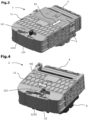
Fig.2 represents, schematically and in perspective, an exploded view of the main parts of an exemplary embodiment of a connector assembly according to the disclosure, -
Fig.3 to Fig.7 represent various steps of mating and unmating a connector according to the disclosure :- ∘ in
Fig.3 , the mating movement of the connector's slider, - ∘ in
Fig.4 , the locking operation of the connector's CPA, - ∘ in
Fig.5 , the connector in its mated position, - ∘ in
Fig.6 , a detail of the connector's CPA in mated position, - ∘ in
Fig.7 , the unlocking of the connector's CPA so as to allow unmating of the connector.
- ∘ in
- In the various figures, similar or identical elements have the same references.
- An example of a
connector assembly 1 according to the present disclosure is shown inFig.1 . Thisconnector assembly 1 comprises aconnector 2 and acounter-connector 3. For example, theconnector 2 is a right-angle connector. For example, theconnector 2 is a female connector. For example, theconnector 2 comprises aninner housing 4, anouter housing 5, shieldingelements 6 inserted between the inner 4 and outer 5 housings. For example, theinner housing 4 has two cavities, each one of which accommodating afemale power terminal 7, as well as sealing means 8 and retaining means 9 (that in particular retains the sealing means 8 in their respective cavity). Eachfemale power terminal 7 is for example crimped at a free end of apower cable 10. Eachfemale power terminal 7 has a mating portion extending longitudinally in a mating direction MD and a crimping portion extending longitudinally essentially perpendicular to the mating direction. - Further, a
mate assist slider 11, is slidably mounted on theouter housing 5. For example, theslider 11 is mounted on theouter housing 5 in a way identical or similar to the one disclosed in the prior art documentWO2012/156486 A1 which is hereby incorporated by reference. Theslider 11 is slidably mounted on theouter housing 5 so as to slide in a sliding direction SD, between an unlocking position (or unengaged) and a locking position or engaged), and vice-versa. For example, the sliding direction SD corresponds to the longitudinal direction of the cavities accommodating the crimping portionfemale power terminals 7. - A
locking button 12 is slidably mounted on theouter housing 5. The function of this locking button is to be a "connection position assurance" (or CPA), similarly to the one disclosed in the prior art documentWO2012/156486 A1 . - The
inner housing 4, theouter housing 5, the retainer means 9, theslider 11, and thelocking button 12 are molded parts made of dielectric materials. Theshielding elements 6 and theterminals 7 are made of electrically conductive materials. A shielding braid is maintained on theconnector 2 with a strap. - The
counter-connector 3 is identical or similar to the one disclosed in the prior art documentWO2012/156486 A1 . - As shown, in particular, in
Fig.1 , theslider 11 comprises atop wall 13, afront wall 14 and twolateral walls 15. Thetop wall 13 essentially faces a mating face through which thefemale power terminals 7 are mated to male power terminals of thecounter-connector 3. In other words, thetop wall 13 extends essentially perpendicularly to the mating direction MD. Thefront wall 14 is essentially parallel to the mating direction MD and perpendicular to a sliding direction SD. Thelateral walls 15 are essentially perpendicular to both thetop wall 13 and thefront wall 14. In other words, thelateral walls 15 extend respectively in a plane which is essentially parallel to the sliding direction SD. - Each
lateral wall 15 has an inner surface onto which are formed at least one groove, as disclosed in the prior art documentWO2012/156486 A1 . Each groove is inclined with respect to the sliding direction SD and is configured to engage a peg protruding from the counter-connector 3 so as to draw theconnector 2 and counter-connector 3 toward each other(along direction MD) and progressively mate them with each other, when theslider 11 is moved along the sliding direction SD, from its unlocking position to its locking position. - Each
lateral wall 15 has anouter surface 23. Theouter surfaces 23 are configured so as to form gripping surfaces for an operator to move theslider 11 along the sliding direction SD, from its unlocking position to its locking position. Thetop wall 13,front wall 14 andlateral walls 15 form a protecting wall. -
Fig.1 shows theconnector 2 with itsslider 11 in open position, i.e. unengaged/unlocked position. While not accessible in its configuration, theCPA lock button 12 is in its unlocked stable position, in this example on the right side of its sliding path. Thetop wall 13 has anopening 120, which is partially covered by ashelter 121. The connector is in condition for making the connection, for example for connecting the wires 10 a battery or a motor device. - For the mating operation, the
connector 2 is first positioned on thecounter connector 3, then theslider 11 is moved M1 according to the arrow on the right for mating the terminals with their respective counter terminals. - As shown in
Fig.4 , once the mating is done, theslider 11 is in engaged position and theunlocked CPA button 12 is now visible and accessible through the right side of theopening 120. - For locking the connection, the
CPA button 12 is then pushed M2 , as shown by the left oriented arrow toward its locked stable position, here on the left side of its sliding path (Fig.5 ). - The unlocked position of the CPA button 12 (
Fig.4 ) extends enough out of theshelter 121 so that it may be pushed by an human finger, until it is hidden by the shelter which correspond to its locked position. - Then, as illustrated in
Fig.5 and Fig.6 , the CPA being clearly hidden under the shelter, and not anymore available for pushing it, means that the electrical connection is completed, which actually fulfils the role of a CPA system. As can be seen in details inFig.6 , theshelter 121 leaves anopen slit 1210 on the front face of theCPA button 120. This slit give a thin access, not enough for inserting a finger, to asmall recess 122 in this front face. - As illustrated in
Fig.7 , when disconnecting is needed, a thin tool such as a small screwdriver 29 may be inserted into theslit 1210 and into therecess 122 of theCPA locking button 12 and used for driving saidbutton 12 out of the shelter and toward its unlocked position as shown by the arrow M3. - Thanks to the masking
shelter 121, and to the smallness of theslit 1210 and/or therecess 122, thelocking button 12 is protected from shocks, and also from involuntary actuating or from any tool-less action. Thelocking button 12 is thus accessible for actuating toward its unlocking position with a tool but not by a human finger, so that the mate assistmember 11 can be manually actuated toward its engaged position, while it cannot be disengaged without a tool. - As the disclosure provides a connector that can be opened for mating without a tool, using it for assembling a vehicle or a subassembly may be done quickly and easily, even if delivered to the assembly station in a closed slider configuration. This is obtained while preventing an untrained person to disconnect such electrical power without some preparation: it may be assumed that a person that knows how to use a tool for unlocking the
CPA button 12 should be sufficiently informed or trained to also have the knowledge of the necessary previous operations, such as shutting down the power before disconnecting theconnector assembly 1. - According to the present disclosure, the locking member (12) used as a "connection , when in its locking position, is accessible for actuating toward its unlocking position with a tool but not by a human finger, so that the mate assist member (11) can be manually actuated toward its engaged position, while it cannot be disengaged without a tool.
- Of course, the disclosure is not limited to the examples just described, and many adjustments can be made to these examples without departing from the scope of the disclosure.
Claims (6)
- Electrical connector (2) comprising,- a housing (4, 5) made of isolating material and accommodating one or several electrical power terminals (7), each power terminal having a mating portion extending longitudinally in a mating direction (MD),- a mate assist member (11), mounted on the housing so as to be movable between at least∘ an unengaged position, where each electric power terminal is in a condition making it possible to start to engage or disengage a counter terminal accommodated within a counter connector (3) adapted to be mated with said electrical connector,∘ and an engaged position where, once said counter connector (3) is mated with said electrical connector (2), each electric power terminal (7) is in a position providing full electrical contact with its respective counter terminal;- a locking member (12), mounted on the connector housing (5) or on the mate assist member (11) so as to be movable upon actuating between at leastcharacterized in that the locking member (12), when in its locking position, is accessible for actuating toward its unlocking position with a tool (129) but not by a human finger, so that the mate assist member (11) can be manually actuated toward its engaged position, while said locking member (12) cannot be disengaged without a tool.∘ a unlocking position, where the mate assist member (2) can be movable toward its engaged position, and∘ a locking position, where the mate assist member (2) cannot be moved out of its engaged position,
- Device according to the preceding claim, characterized in that the locking member comprises a locking button (12) with a first actuating surface that, when said button is in its unlocking position, can be manually pushed for actuating (M2) said button toward its locking position,
and in that the connector (2) comprises a fixed part (121) that, when said button (12) is in its unlocking position, covers at least partially the locking button (12) so that the only surface that can be used for actuating said button toward its unlocking position is accessible by a tool thinner than a human finger but not by a human finger. - Device according to the preceding claim, characterized in that the mate assist member comprises a slider (11) which is movable in relation to the housing (5),
- Device according to the preceding claim, characterized in that the locking button (12) is slidably mounted on or through the slider (11), and
in that the locking position of said locking button is retracted under a fixed part (121) of said slider that covers and deny access to all the surfaces of said locking button that are facing oppositely, or more than 90°, to its first actuating surface and that are large enough for being finger-pushed toward its unlocking position. - Device according to any one of claims 2 to 4, characterized in that the fixed part (121) that covers the locking position of the locking button (12) leaves, along the moving path of said locking button, a slit (1210) through which a tool (129) thinner than a human finger may actuate it by a slot (122) provided in a lateral surface of said locking button (12).
- Method of electrically connecting together a first device comprising an electrical connector (2) according to any one of claims 1 to 5, with a second device comprising a counter connector (3) compatible with said connector, said method comprising the following steps:- providing said first device to an assembling place, with its mate assist member (11) in its engaged position and its locking member (12) in its unlocking position, the mate assist member thus being in a condition similar to its intended mated position,- manually actuating said mate assist member (11) to its disengaged position, preferably without using a tool,- mating said connector (2) with said counter connector (3) with actuating (M1) said mate assist member (11) to its engaged position,- manually actuating (M2) said locking member (12) to its locking position, thus achieving a connected state that cannot be undone by a manual voluntary or manual involuntary operation.
Priority Applications (1)
| Application Number | Priority Date | Filing Date | Title |
|---|---|---|---|
| EP23181432.8A EP4485708A1 (en) | 2023-06-26 | 2023-06-26 | Electrical power connector with locking cpa and method for using it in a connection |
Applications Claiming Priority (1)
| Application Number | Priority Date | Filing Date | Title |
|---|---|---|---|
| EP23181432.8A EP4485708A1 (en) | 2023-06-26 | 2023-06-26 | Electrical power connector with locking cpa and method for using it in a connection |
Publications (1)
| Publication Number | Publication Date |
|---|---|
| EP4485708A1 true EP4485708A1 (en) | 2025-01-01 |
Family
ID=87047821
Family Applications (1)
| Application Number | Title | Priority Date | Filing Date |
|---|---|---|---|
| EP23181432.8A Pending EP4485708A1 (en) | 2023-06-26 | 2023-06-26 | Electrical power connector with locking cpa and method for using it in a connection |
Country Status (1)
| Country | Link |
|---|---|
| EP (1) | EP4485708A1 (en) |
Citations (4)
| Publication number | Priority date | Publication date | Assignee | Title |
|---|---|---|---|---|
| WO2012156486A1 (en) | 2011-05-18 | 2012-11-22 | Fci Automotive Holding | Electrical connector assembly, and connector for such assembly |
| EP2690720A1 (en) * | 2012-07-26 | 2014-01-29 | Amphenol Air LB | Cable connector with quick assembly |
| KR20140064289A (en) * | 2012-11-20 | 2014-05-28 | 한국단자공업 주식회사 | Lever type connector |
| DE102017215516A1 (en) * | 2017-09-05 | 2019-03-07 | Te Connectivity Germany Gmbh | Electrical connector with finger release protection |
-
2023
- 2023-06-26 EP EP23181432.8A patent/EP4485708A1/en active Pending
Patent Citations (4)
| Publication number | Priority date | Publication date | Assignee | Title |
|---|---|---|---|---|
| WO2012156486A1 (en) | 2011-05-18 | 2012-11-22 | Fci Automotive Holding | Electrical connector assembly, and connector for such assembly |
| EP2690720A1 (en) * | 2012-07-26 | 2014-01-29 | Amphenol Air LB | Cable connector with quick assembly |
| KR20140064289A (en) * | 2012-11-20 | 2014-05-28 | 한국단자공업 주식회사 | Lever type connector |
| DE102017215516A1 (en) * | 2017-09-05 | 2019-03-07 | Te Connectivity Germany Gmbh | Electrical connector with finger release protection |
Similar Documents
| Publication | Publication Date | Title |
|---|---|---|
| US8628344B2 (en) | Connector and terminal positioning mechanism | |
| US8192212B2 (en) | Electrical connector system with temporarily blocking during unmating of two connectors | |
| KR102556351B1 (en) | Right angle connector with terminal contact protection | |
| US9455523B1 (en) | Right angle connection assembly | |
| US6648669B1 (en) | Electrical connection with sequential disconnect | |
| EP0622869B1 (en) | Connector device | |
| CN103004031B (en) | Plug-type connector having a radially acting latching device | |
| US8241052B2 (en) | Electrical connector system with power and command connectors | |
| CN112534651B (en) | Electrical connector with terminal position assurance device | |
| CN110690625B (en) | connector device | |
| CN110571567B (en) | Staged release electrical connector assembly | |
| CN107453125B (en) | Locking device for an electrical connector and electrical connector provided with such a device | |
| JP2007149420A (en) | Lever fitting type connector | |
| JP2020080300A (en) | Coupling connector with slider section | |
| US5913691A (en) | Dual power/control connector | |
| EP3769377B1 (en) | Connector position assurance member | |
| CN112673531A (en) | Electrical connector, plug connector, high-voltage system and method for locking an electrical plug connector | |
| CN113826287B (en) | Plug-in connector part capable of being separated safely | |
| CN112714984A (en) | Electrical plug-in connection, vehicle and method for locking an electrical plug-in connection | |
| US20120302084A1 (en) | Bi-directional cpa member to prevent unmating of multiple connectors | |
| US20030186579A1 (en) | Connector and a connector assembly | |
| EP4618320A1 (en) | Fastener position assurance device and connector assembly | |
| EP4462610A1 (en) | Electrical power connector and method for unmating the same | |
| WO2020183255A1 (en) | Connector position assurance member | |
| KR101632708B1 (en) | Connector assembly |
Legal Events
| Date | Code | Title | Description |
|---|---|---|---|
| STAA | Information on the status of an ep patent application or granted ep patent |
Free format text: STATUS: UNKNOWN |
|
| PUAI | Public reference made under article 153(3) epc to a published international application that has entered the european phase |
Free format text: ORIGINAL CODE: 0009012 |
|
| STAA | Information on the status of an ep patent application or granted ep patent |
Free format text: STATUS: THE APPLICATION HAS BEEN PUBLISHED |
|
| AK | Designated contracting states |
Kind code of ref document: A1 Designated state(s): AL AT BE BG CH CY CZ DE DK EE ES FI FR GB GR HR HU IE IS IT LI LT LU LV MC ME MK MT NL NO PL PT RO RS SE SI SK SM TR |
|
| STAA | Information on the status of an ep patent application or granted ep patent |
Free format text: STATUS: REQUEST FOR EXAMINATION WAS MADE |
|
| 17P | Request for examination filed |
Effective date: 20250623 |