EP4485702A1 - Connector assembly - Google Patents
Connector assembly Download PDFInfo
- Publication number
- EP4485702A1 EP4485702A1 EP24175737.6A EP24175737A EP4485702A1 EP 4485702 A1 EP4485702 A1 EP 4485702A1 EP 24175737 A EP24175737 A EP 24175737A EP 4485702 A1 EP4485702 A1 EP 4485702A1
- Authority
- EP
- European Patent Office
- Prior art keywords
- connector
- contact
- retention member
- retention
- fitting
- Prior art date
- Legal status (The legal status is an assumption and is not a legal conclusion. Google has not performed a legal analysis and makes no representation as to the accuracy of the status listed.)
- Granted
Links
Images






Classifications
-
- H—ELECTRICITY
- H01—ELECTRIC ELEMENTS
- H01R—ELECTRICALLY-CONDUCTIVE CONNECTIONS; STRUCTURAL ASSOCIATIONS OF A PLURALITY OF MUTUALLY-INSULATED ELECTRICAL CONNECTING ELEMENTS; COUPLING DEVICES; CURRENT COLLECTORS
- H01R13/00—Details of coupling devices of the kinds covered by groups H01R12/70 or H01R24/00 - H01R33/00
- H01R13/62—Means for facilitating engagement or disengagement of coupling parts or for holding them in engagement
- H01R13/639—Additional means for holding or locking coupling parts together, after engagement, e.g. separate keylock, retainer strap
-
- H—ELECTRICITY
- H01—ELECTRIC ELEMENTS
- H01R—ELECTRICALLY-CONDUCTIVE CONNECTIONS; STRUCTURAL ASSOCIATIONS OF A PLURALITY OF MUTUALLY-INSULATED ELECTRICAL CONNECTING ELEMENTS; COUPLING DEVICES; CURRENT COLLECTORS
- H01R13/00—Details of coupling devices of the kinds covered by groups H01R12/70 or H01R24/00 - H01R33/00
- H01R13/02—Contact members
- H01R13/10—Sockets for co-operation with pins or blades
- H01R13/11—Resilient sockets
- H01R13/111—Resilient sockets co-operating with pins having a circular transverse section
-
- H—ELECTRICITY
- H01—ELECTRIC ELEMENTS
- H01R—ELECTRICALLY-CONDUCTIVE CONNECTIONS; STRUCTURAL ASSOCIATIONS OF A PLURALITY OF MUTUALLY-INSULATED ELECTRICAL CONNECTING ELEMENTS; COUPLING DEVICES; CURRENT COLLECTORS
- H01R13/00—Details of coupling devices of the kinds covered by groups H01R12/70 or H01R24/00 - H01R33/00
- H01R13/02—Contact members
- H01R13/22—Contacts for co-operating by abutting
- H01R13/24—Contacts for co-operating by abutting resilient; resiliently-mounted
- H01R13/2464—Contacts for co-operating by abutting resilient; resiliently-mounted characterized by the contact point
- H01R13/2471—Contacts for co-operating by abutting resilient; resiliently-mounted characterized by the contact point pin shaped
-
- H—ELECTRICITY
- H01—ELECTRIC ELEMENTS
- H01R—ELECTRICALLY-CONDUCTIVE CONNECTIONS; STRUCTURAL ASSOCIATIONS OF A PLURALITY OF MUTUALLY-INSULATED ELECTRICAL CONNECTING ELEMENTS; COUPLING DEVICES; CURRENT COLLECTORS
- H01R13/00—Details of coupling devices of the kinds covered by groups H01R12/70 or H01R24/00 - H01R33/00
- H01R13/62—Means for facilitating engagement or disengagement of coupling parts or for holding them in engagement
- H01R13/6205—Two-part coupling devices held in engagement by a magnet
-
- H—ELECTRICITY
- H01—ELECTRIC ELEMENTS
- H01R—ELECTRICALLY-CONDUCTIVE CONNECTIONS; STRUCTURAL ASSOCIATIONS OF A PLURALITY OF MUTUALLY-INSULATED ELECTRICAL CONNECTING ELEMENTS; COUPLING DEVICES; CURRENT COLLECTORS
- H01R11/00—Individual connecting elements providing two or more spaced connecting locations for conductive members which are, or may be, thereby interconnected, e.g. end pieces for wires or cables supported by the wire or cable and having means for facilitating electrical connection to some other wire, terminal, or conductive member, blocks of binding posts
- H01R11/11—End pieces or tapping pieces for wires, supported by the wire and for facilitating electrical connection to some other wire, terminal or conductive member
- H01R11/30—End pieces held in contact by a magnet
-
- H—ELECTRICITY
- H01—ELECTRIC ELEMENTS
- H01R—ELECTRICALLY-CONDUCTIVE CONNECTIONS; STRUCTURAL ASSOCIATIONS OF A PLURALITY OF MUTUALLY-INSULATED ELECTRICAL CONNECTING ELEMENTS; COUPLING DEVICES; CURRENT COLLECTORS
- H01R12/00—Structural associations of a plurality of mutually-insulated electrical connecting elements, specially adapted for printed circuits, e.g. printed circuit boards [PCB], flat or ribbon cables, or like generally planar structures, e.g. terminal strips, terminal blocks; Coupling devices specially adapted for printed circuits, flat or ribbon cables, or like generally planar structures; Terminals specially adapted for contact with, or insertion into, printed circuits, flat or ribbon cables, or like generally planar structures
- H01R12/70—Coupling devices
- H01R12/77—Coupling devices for flexible printed circuits, flat or ribbon cables or like structures
- H01R12/79—Coupling devices for flexible printed circuits, flat or ribbon cables or like structures connecting to rigid printed circuits or like structures
-
- H—ELECTRICITY
- H01—ELECTRIC ELEMENTS
- H01R—ELECTRICALLY-CONDUCTIVE CONNECTIONS; STRUCTURAL ASSOCIATIONS OF A PLURALITY OF MUTUALLY-INSULATED ELECTRICAL CONNECTING ELEMENTS; COUPLING DEVICES; CURRENT COLLECTORS
- H01R13/00—Details of coupling devices of the kinds covered by groups H01R12/70 or H01R24/00 - H01R33/00
- H01R13/62—Means for facilitating engagement or disengagement of coupling parts or for holding them in engagement
- H01R13/627—Snap or like fastening
- H01R13/6271—Latching means integral with the housing
Definitions
- the present invention relates to a connector assembly, particularly to a connector assembly in which a first connector and a second connector are fitted together by use of a magnetic force.
- a connector assembly serving to maintain a fitted state using the magnetic force is disclosed in, for instance, JP 2020-30906 A .
- the connector assembly includes a first connector 1 sewn and fixed to clothes or the like and a second connector 2 to be fitted to the first connector 1 as shown in FIG. 35 .
- the second connector 2 includes: a plurality of second contacts 3 disposed on a surface, facing the first connector 1, of the second connector 2 and each constituted of a so-called pogo pin; and two yokes 4 of plate shape attached to a magnet installed inside the second connector 2 and partially exposed on the surface, facing the first connector 1, of the second connector 2.
- the first connector 1 includes a plate-shaped housing 5, and the housing 5 is provided, on its surface facing the second connector 2, with a plurality of first contacts 6 and a plurality of retention members 7 made of magnetic metal or magnet as shown in FIG. 36 .
- the retention members 7 of the first connector 1 are attracted to the two yokes 4 of the second connector 2 by the magnetic force, and the second contacts 3 of the second connector 2 elastically make contact with the first contacts 6 of the first connector 1, whereby the first contacts 6 are electrically connected to the second contacts 3.
- the present invention has been made to solve the foregoing conventional problems and aims at providing a connector assembly capable of improving the reliability of electric connection while easily establishing the fitted state between a first connector and a second connector.
- a connector assembly according to the present invention is one in which a first connector and a second connector are fitted together along a fitting direction
- FIG. 1 shows a connector assembly according to Embodiment 1.
- the connector assembly includes a first connector 11 and a second connector 21 to be fitted to the first connector 11 along a fitting direction.
- the first connector 11 is used as, for example, a garment-side connector for connecting a wearable device and includes six first contacts 12 protruding toward the second connector 21.
- the six first contacts 12 are aligned in two rows and attached to a sheet type conductive member 14 via a reinforcement sheet 13.
- the reinforcement sheet 13 and the sheet type conductive member 14 are defined as extending along an XY plane, the direction in which the first contacts 12 are aligned in two rows is referred to as "Y direction,” and the direction from the first connector 11 toward the second connector 21 is referred to as "+Z direction.”
- the Z direction is the fitting direction in which the first connector 11 and the second connector 21 are fitted together.
- FIG. 2 shows an assembly view of the first connector 11.
- Six first retention members 15 are disposed on the -Z direction side of the six first contacts 12, the reinforcement sheet 13 and the sheet type conductive member 14 are sequentially disposed on the -Z direction side of the six first retention members 15, and six first insulators 16 are disposed on the -Z direction side of the sheet type conductive member 14.
- the sheet type conductive member 14 includes an insulating sheet body 14A, six through-holes 14B formed in the sheet body 14A and corresponding to the six first contacts 12, and six flexible conductors 14C exposed around the corresponding through-holes 14B at least on the surface of the sheet body 14A on the +Z direction side.
- the sheet body 14A for example, cloth or knitted fabric of a garment may be used, and the flexible conductors 14C can be formed by embroidering the sheet body 14A with an embroidery thread constituted of a conductive thread.
- the reinforcement sheet 13 is used to reinforce the sheet body 14A of the sheet type conductive member 14 on which the first connector 11 is mounted.
- the reinforcement sheet 13 is made of an insulating material and has six through-holes 13A corresponding to the six first contacts 12.
- the sheet type conductive member 14 and the reinforcement sheet 13 have flexibility.
- the first contact 12 is formed of an electrically conductive material such as metal, has a tubular shape, specifically a cylindrical shape, extending in the Z direction, and is provided in its inside with a recess portion 12A opening in the -Z direction.
- the first contact 12 is provided at its upper portion with a first contact portion 12B having a circular flat shape extending along an XY plane and facing in the +Z direction.
- the first retention member 15 is formed of a magnetic body and includes a tubular portion 15A extending in the Z direction and a flange 15B extending out of the tubular portion 15A from the -Z directional end of the tubular portion 15A along an XY plane.
- the tubular portion 15A is provided with a through-hole 15C penetrating the first retention member 15 in the Z direction.
- the through-hole 15C has an inner diameter substantially the same as the inner diameter of the recess portion 12A of the first contact 12.
- the -Z directional end of the tubular portion 15A in contact with the flange 15B is provided with an annular groove 15D along the outer periphery of the tubular portion 15A.
- the first insulator 16 is formed of, for instance, insulating resin and includes a base portion 16A of disc shape extending in an XY plane and a projection 16B projecting in the +Z direction from the center of the base portion 16A.
- the projection 16B is provided with a plurality of ribs 16C radially protruding and extending in the Z direction.
- the projection 16B is sized to be able to compress the sheet type conductive member 14 in the thickness direction of the sheet type conductive member 14 when being inserted into the through-hole 15C of the tubular portion 15A of the first retention member 15 and the recess portion 12A of the first contact 12 while pushing the sheet type conductive member 14 thereinto.
- FIG. 6 shows a cross-sectional view corresponding to one first contact 12 of the first connector 11 that is assembled using the thus configured first contacts 12, first retention members 15, reinforcement sheet 13, sheet type conductive member 14, and first insulators 16.
- the reinforcement sheet 13 is stacked on the sheet type conductive member 14 with the through-holes 14B and 13A being aligned, and the first retention member 15 and the first contact 12 are sequentially disposed in a coaxial manner on the reinforcement sheet 13 to be aligned with the through-hole 13A; in this state, the projection 16B of the first insulator 16 is pushed in the +Z direction from the -Z direction of the sheet type conductive member 14 through the through-hole 14B of the sheet type conductive member 14. The projection 16B is sequentially inserted into the through-hole 15C of the first retention member 15 and the recess portion 12A of the first contact 12 while pushing a part of the sheet type conductive member 14 situated around the through-hole 14B thereinto.
- the sheet type conductive member 14 is sandwiched between the rib 16C of the projection 16B and the inner surface of the through-hole 15C of the first retention member 15 and between the rib 16C of the projection 16B and the inner surface of the recess portion 12A of the first contact 12 and compressed in a direction along an XY plane.
- the flexible conductor 14C exposed on the surface of the sheet type conductive member 14 makes contact with the inner surface of the recess portion 12A at a predetermined contact pressure, whereby the first contact 12 is electrically connected to the flexible conductor 14C.
- first retention member 15 and the first contact 12 are joined together in the Z direction via the projection 16B of the first insulator 16 and the sheet type conductive member 14.
- the base portion 16A of the first insulator 16 comes into contact with the rear surface, on the -Z direction side, of the sheet type conductive member 14.
- the six first contacts 12 of the first connector 11 are all electrically connected to the corresponding flexible conductors 14C and also joined to the corresponding first retention members 15 by the connection structure illustrated in FIG. 6 .
- FIG. 7 shows an assembly view of the second connector 21.
- Six second contacts 23 are disposed on the -Z direction side of a substrate 22, six second insulators 24 are disposed on the -Z direction side of the six second contacts 23, six magnets 25 are disposed on the -Z direction side of the six second insulators 24, and six retention plates 26 are disposed on the -Z direction side of the six magnets 25.
- the six second contacts 23 are arranged to correspond in position to the six first contacts 12 of the first connector 11.
- the second contact 23 is constituted of a so-called pogo pin and includes a barrel 23A extending in the Z direction and a plunger 23B disposed to be elastically movable forward and backward in the Z direction within the barrel 23A. More specifically, a spring member (not shown) is disposed inside the barrel 23A and imparts an elastic force acting in the -Z direction to the plunger 23B.
- the plunger 23B is provided at its -Z directional end with a second contact portion 23C of pin shape that faces in the -Z direction.
- the magnet 25 has the shape of a curved plate being curved in an XY plane and extending in the Z direction and is magnetized such that magnetic field lines act mainly in the +Y direction.
- the curved shape of the magnet 25 in an XY plane has a curvature that allows the curved shape to follow an outer peripheral portion of the tubular portion 15A of the first retention member 15 of the first connector 11.
- the retention plate 26 is formed of a magnetic body and includes a curved portion 26A being curved in an XY plane and extending in the Z direction and a pair of flat portions 26B extending in the Z direction at the opposite ends of the curved shape of the curved portion 26A.
- the curved portion 26A is curved to follow an outer peripheral portion of the magnet 25, and the retention plate 26 has such a shape as to cover the curved surface facing in the -Y direction and the +X and -X directional lateral surfaces of the magnet 25.
- the retention plate 26 formed of a magnetic body is attracted by and attached to the magnet 25 by the magnetic force.
- the magnet 25 and the retention plate 26 as above together form a second retention member 27.
- the -Z directional end of the magnet 25 protrudes in the - Z direction out of the -Z directional end of the retention plate 26.
- the pair of flat portions 26B of the retention plate 26 are separately provided at their -Z directional ends with a pair of protrusion portions 26C protruding along the surfaces of the flat portions 26B on the +Y direction side.
- the pair of protrusion portions 26C each protrude in a direction toward the center of the curved shape of the curved portion 26A.
- Each protrusion portion 26C has a height dimension in the Z direction slightly smaller than the width in the Z direction of the annular groove 15D of the first retention member 15 shown in FIG. 4 and therefore can be fitted in the annular groove 15D of the first retention member 15.
- a lock receiving portion of the first connector 11 is formed by the annular groove 15D of the first retention member 15 shown in FIG. 4
- a lock portion of the second connector 21 is formed by the pair of protrusion portions 26C of the second retention member 27 shown in FIG. 11 .
- the pair of protrusion portions 26C of the second retention member 27 are fitted in the annular groove 15D of the first retention member 15 along the Y direction (predetermined direction), thereby locking the fitting between the first connector 11 and the second connector 21.
- FIGS. 12 and 13 show a perspective view and a cross-sectional view corresponding to one second contact 23 of the second connector 21.
- the second insulator 24 is disposed on the -Z direction side of the substrate 22.
- the second insulator 24 has a cylindrical outer shape and is provided in its inside with a first contact accommodating portion 24A of recess shape that opens in the -Z direction and a second retention member accommodating portion 24B of recess shape that opens in the -Z direction.
- the first contact accommodating portion 24A and the second retention member accommodating portion 24B are disposed to be adjacent to each other and communicate with each other within the second insulator 24.
- the first contact accommodating portion 24A has an elliptical shape elongated in the Y direction (predetermined direction) when viewed from the -Z direction
- the second retention member accommodating portion 24B is disposed to be adjacent to the -Y directional end of the first contact accommodating portion 24A. Since the first contact accommodating portion 24A has an elliptical shape elongated in the Y direction, the second connector 21 is slidable in the Y direction (predetermined direction) with respect to the first connector 11 with the first contact 12 of the first connector 11 being accommodated in the first contact accommodating portion 24A from the -Z direction.
- the bottom of the first contact accommodating portion 24A is provided with a second contact accommodating hole 24C that is situated on the central axis, which extends in the Z direction, of the second insulator 24 having a cylindrical outer shape and that penetrates the second insulator 24 in the Z direction.
- a wiring portion 22A is formed on the rear surface of the substrate 22 on the -Z direction side as shown in FIG. 12 .
- the second contact 23 is mounted on the substrate 22 so as to be connected to the wiring portion 22A and accommodated in the second contact accommodating hole 24C of the second insulator 24.
- the plunger 23B of the second contact 23 protrudes within the first contact accommodating portion 24A of the second insulator 24 through the second contact accommodating hole 24C, and the second contact portion 23C formed at the -Z directional end of the plunger 23B is exposed within the first contact accommodating portion 24A.
- Each of the six second insulators 24 of the second connector 21 is disposed on the -Z direction side of the substrate 22, the second contact 23 is accommodated in the second contact accommodating hole 24C of the corresponding second insulator 24, and the second retention member 27 is accommodated in the second retention member accommodating portion 24B of the corresponding second insulator 24, as shown in FIG. 13 .
- the retention plate 26 is bonded and fixed to the inner peripheral surface of the second retention member accommodating portion 24B of the second insulator 24 and the +Z directional end of the magnet 25 is bonded and fixed to the bottom, on the +Z direction side, of the second retention member accommodating portion 24B of the second insulator 24, the retention plate 26 formed of a magnetic body is attracted by and attached to the magnet 25 by the magnetic force.
- the orientations of the six second insulators 24 in an XY plane are uniform; specifically, in each second insulator 24, the first contact accommodating portion 24A has an elliptical shape elongated in the Y direction, and the second retention member accommodating portion 24B is disposed to be adjacent to the - Y directional end of the first contact accommodating portion 24A.
- the second connector 21 is placed on the +Z direction side of the first connector 11, and the first connector 11 and the second connector 21 are positioned with respect to each other such that the +Y directional end of the first contact accommodating portion 24A of elliptical shape elongated in the Y direction of the second insulator 24 is aligned with the +Z direction side of the +Y directional end of the first contact 12.
- the second connector 21 is relatively moved in the -Z direction toward the first connector 11, whereby the first contact 12 of the first connector 11 is accommodated into the first contact accommodating portion 24A of the second insulator 24 of the second connector 21 as shown in FIG. 15 .
- the second contact portion 23C formed on the plunger 23B of the second contact 23 of the second connector 21 makes contact with the first contact portion 12B in a flat shape of the first contact 12 of the first connector 11, so that a part of the plunger 23B is elastically retracted into the barrel 23A.
- the first contact portion 12B thus contacts the second contact portion 23C in the Z direction at a predetermined contact pressure, so that the first contact 12 and the second contact 23 are electrically connected together.
- the magnet 25 of the second retention member 27 abuts on the flange 15B of the first retention member 15 formed of a magnetic body, the magnet 25 is attracted by and attached to the flange 15B by the magnetic force, thus maintaining the contacting state between the first contact portion 12B and the second contact portion 23C in the Z direction.
- the position of the second connector 21 with respect to the first connector 11 at this time is called a fitting start position P1.
- the first contact 12 is accommodated in a position offset to the +Y direction side within the first contact accommodating portion 24A of elliptical shape elongated in the Y direction, as shown in FIG. 16 .
- the plunger 23B of the second contact 23 is situated in an eccentric position with respect to the circular first contact portion 12B of the first contact 12.
- a gap is formed between the -Y directional end of the first contact 12 and the second retention member 27, so that the second connector 21 can be relatively moved in the -Z direction to the fitting start position P1 with no interference between the protrusion portion 26C, which protrudes on the +Y direction side from the - Z directional end of the retention plate 26 of the second retention member 27, and the first contact 12 or the tubular portion 15A of the first retention member 15, as shown in FIG. 17 .
- the second connector 21 When the second connector 21 is in the fitting start position P1 as shown in FIGS. 15 to 17 , the first contact 12 and the second contact 23 are electrically connected together because the first contact portion 12B contacts the second contact portion 23C in the Z direction at a predetermined contact pressure, and the second connector 21 is in the fitting start position P1 with respect to the first connector 11 only with the magnetic force acting between the magnet 25 of the second retention member 27 and the flange 15B of the first retention member 15.
- first contact 12 and the second contact 23 are connected together with the plunger 23B of the second contact 23 being elastically retracted, a force acting in the direction of separating the first connector 11 and the second connector 21 from each other in the Z direction is exerted from the second contact 23.
- the second connector 21 is relatively slid in the +Y direction with respect to the first connector 11 until the second retention member 27 of the second connector 21 makes contact with or closely approaches the tubular portion 15A of the first retention member 15 of the first connector 11, as shown in FIG. 18 .
- the second connector 21 is slid with respect to the first connector 11 until the magnet 25 of the second retention member 27 makes contact with or closely approaches the -Y directional end of the tubular portion 15A of the first retention member 15.
- the second contact portion 23C of the second contact 23 slides in the +Y direction with respect to the first contact portion 12B while maintaining contact with the first contact portion 12B of the first contact 12.
- the electric connection between the first contact 12 and the second contact 23 is maintained.
- the first contact 12 is positioned on the -Y direction side within the first contact accommodating portion 24A of elliptical shape elongated in the Y direction, so that the plunger 23B of the second contact 23 is situated in the center of the circular first contact portion 12B of the first contact 12.
- the pair of protrusion portions 26C protruding on the +Y direction side from the -Z directional ends of the pair of flat portions 26B of the retention plate 26 of the second retention member 27 are fitted into the annular groove 15D formed in the tubular portion 15A of the first retention member 15, as shown in FIG. 20 .
- the lock portion formed by the pair of protrusion portions 26C is fitted in the lock receiving portion formed by the annular groove 15D, whereby the second connector 21 is prevented from moving in the +Z direction with respect to the first connector 11, thus maintaining the electrically connected state between the first contact 12 and the second contact 23 through the contact between the first contact portion 12B and the second contact portion 23C.
- the second connector 21 is thus fitted to the first connector 11.
- the position of the second connector 21 with respect to the first connector 11 at this time is called a fitting completed position P2.
- the magnetic force acts between the magnet 25 and the tubular portion 15A formed of a magnetic body to attract them to each other in the Y direction, and this keeps the second connector 21 in the fitting completed position P2 with respect to the first connector 11.
- the second contact 23 of the second connector 21 is electrically connected to the corresponding flexible conductor 14C of the sheet type conductive member 14 via the first contact 12 of the first connector 11.
- the six second insulators 24 of the second connector 21 are disposed on the -Z direction side of the substrate 22 with their orientations being uniform in an XY plane, when the substrate 22 is relatively moved in the -Z direction toward the first connector 11, the state where the second connector 21 is in the fitting start position P1 with respect to the first connector 11 is formed in each of the six second insulators 24, and further, when the substrate 22 is relatively slid in the +Y direction with respect to the first connector 11, the state where the second connector 21 is in the fitting completed position P2 with respect to the first connector 11 is formed in each of the six second insulators 24.
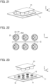
- the fitted state is established between the first connector 11 and the second connector 21 as shown in FIG. 21 .
- the six second insulators 24 of the second connector 21 need to be uniformly oriented in an XY plane, for instance, the six second insulators 24 may be formed by resin molding to be joined together via a joint member C as shown in FIG. 22 .
- the six second insulators 24 are molded to be joined while keeping their positional relation that is required when disposed on the substrate 22, and the six second contacts 23 mounted on the substrate 22 are accommodated into the six second insulators 24 that are still joined, whereby the six second insulators 24 are disposed on the substrate 22.
- the second retention members 27 are accommodated into the corresponding second insulators 24.
- the joint member C is cut and removed from the six second insulators 24.
- the second connector 21 can be fabricated with the second insulators 24 being in a uniform orientation.
- FIG. 23 shows a connector assembly according to Embodiment 2.
- the connector assembly is configured such that in the connector assembly according to Embodiment 1, a first connector 11 is fitted to a second connector 31 in place of the second connector 21, and the first connector 11 is the same as that used in Embodiment 1.
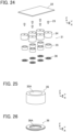
- FIG. 24 shows an assembly view of the second connector 31.
- Six second contacts 23 are disposed on the -Z direction side of a substrate 22, six second insulators 34 are disposed on the -Z direction side of the six second contacts 23, six magnets 35 are disposed on the -Z direction side of the six second insulators 34, and six retention plates 36 are disposed on the -Z direction side of the six magnets 35.
- the substrate 22 and the six second contacts 23 are the same as those used in Embodiment 1.
- the magnet 35 has a cylindrical shape extending in the Z direction and is provided in its inside with a through-hole 35A that penetrates the magnet 35 in the Z direction.
- the magnet 35 is magnetized such that magnetic field lines act mainly in the +Y direction.
- the retention plate 36 is formed of a magnetic body and constituted of a ring member extending in a flat plate form along an XY plane.
- the retention plate 36 is provided with a through-hole 36A that penetrates the retention plate 36 in the Z direction.
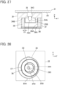
- FIG. 27 shows a cross-sectional view corresponding to one second contact 23 of the second connector 31.
- the second insulator 34 is disposed on the -Z direction side of the substrate 22.
- the second insulator 34 has a cylindrical outer shape and is provided in its inside with a first contact accommodating portion 34A of recess shape that opens in the -Z direction and a second retention member accommodating portion 34B of recess shape that opens in the -Z direction.
- the second retention member accommodating portion 34B is situated outside the first contact accommodating portion 34A to surround the first contact accommodating portion 34A and communicates with the first contact accommodating portion 34A.
- the bottom of the first contact accommodating portion 34A is provided with a second contact accommodating hole 34C that is situated on the central axis, which extends in the Z direction, of the second insulator 34 having a cylindrical outer shape and that penetrates the second insulator 34 in the Z direction.
- the second contact 23 mounted on the substrate 22 is accommodated in the second contact accommodating hole 34C of the second insulator 34, the plunger 23B of the second contact 23 protrudes within the first contact accommodating portion 34A of the second insulator 34 through the second contact accommodating hole 34C, and the second contact portion 23C formed at the -Z directional end of the plunger 23B is exposed within the first contact accommodating portion 34A.
- the cylindrical magnet 35 is accommodated in the second retention member accommodating portion 34B of the second insulator 34.
- the retention plate 36 constituted of a ring member formed of a magnetic body is press-fitted or bonded and thereby fixed to the -Z directional open end of the second retention member accommodating portion 34B of the second insulator 34, and attracted by and attached to the -Z directional end of the magnet 35 by the magnetic force.
- the magnet 35 and the retention plate 36 as above together form a second retention member 37.
- the retention plate 36 constituted of a ring member has the same outer diameter as the outer diameter of the cylindrical magnet 35, and the through-hole 36A of the retention plate 36 has an inner diameter smaller than the inner diameter of the through-hole 35A of the magnet 35, so that a step D1 is formed between the inner surface of the through-hole 36A of the retention plate 36 and the inner surface of the through-hole 35A of the magnet 35, and an edge portion of the through-hole 36A of the retention plate 36 protrudes inside the through-hole 35A of the magnet 35, as shown in FIG. 27 .
- the retention plate 36 has a thickness in the Z direction slightly smaller than the width in the Z direction of the annular groove 15D of the first retention member 15 shown in FIG. 4 , so that the edge portion of the through-hole 36A of the retention plate 36 that protrudes inside the through-hole 35A of the magnet 35 can be fitted in the annular groove 15D of the first retention member 15.
- the through-hole 36A of the retention plate 36 is sized to allow the first contact 12 and the tubular portion 15A of the first retention member 15 to pass therethrough in the Z direction.
- the first contact accommodating portion 34A has an elliptical shape elongated in the Y direction (predetermined direction) when viewed from the -Z direction. Accordingly, the second connector 31 is slidable in the Y direction (predetermined direction) with respect to the first connector 11 with the first contact 12 of the first connector 11 being accommodated in the first contact accommodating portion 34A from the -Z direction.
- the second retention member 37 is situated in an eccentric position in the +Y direction with respect to the second insulator 34 having a cylindrical outer shape.
- Each of the six second insulators 34 of the second connector 31 is disposed on the -Z direction side of the substrate 22, the second contact 23 is accommodated in the second contact accommodating hole 34C of the corresponding second insulator 34, and the second retention member 37 is accommodated in the second retention member accommodating portion 34B of the corresponding second insulator 34, as shown in FIG. 27 .
- the orientations of the six second insulators 34 in an XY plane are uniform, and in each second insulator 34, the first contact accommodating portion 34A has an elliptical shape elongated in the Y direction as shown in FIG. 28 .
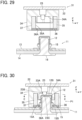
- the second connector 31 is placed on the +Z direction side of the first connector 11, and the first connector 11 and the second connector 31 are positioned with respect to each other such that the +Y directional end of the first contact accommodating portion 34A of elliptical shape elongated in the Y direction of the second insulator 34 is aligned with the +Z direction side of the +Y directional end of the first contact 12.
- the second connector 31 is relatively moved in the -Z direction toward the first connector 11, whereby the first contact 12 of the first connector 11 is accommodated into the first contact accommodating portion 34A of the second insulator 34 of the second connector 31 as shown in FIG. 30 .
- the second contact portion 23C formed on the plunger 23B of the second contact 23 of the second connector 31 makes contact with the first contact portion 12B in a flat shape of the first contact 12 of the first connector 11, so that a part of the plunger 23B is elastically retracted into the barrel 23A.
- the first contact portion 12B thus contacts the second contact portion 23C in the Z direction at a predetermined contact pressure, so that the first contact 12 and the second contact 23 are electrically connected together.
- the magnet 35 is attracted by and attached to the flange 15B by the magnetic force via the retention plate 36, thus maintaining the contacting state between the first contact portion 12B and the second contact portion 23C in the Z direction.
- the position of the second connector 31 with respect to the first connector 11 at this time is called a fitting start position P1.
- the first contact 12 is accommodated in a position offset to the +Y direction side within the first contact accommodating portion 34A of elliptical shape elongated in the Y direction as shown in FIG. 31 .
- a gap is formed between the -Y directional end of the first contact 12 and the -Y directional end of the interior of the first contact accommodating portion 34A, so that the second connector 31 can be relatively moved in the -Z direction to the fitting start position P1 with no interference between the edge portion of the through-hole 36A of the retention plate 36 of the second retention member 37 and the first contact 12 or the tubular portion 15A of the first retention member 15 as shown in FIG. 30 .
- the second connector 31 When the second connector 31 is in the fitting start position P1 as shown in FIG. 30 , the first contact 12 and the second contact 23 are electrically connected together because the first contact portion 12B contacts the second contact portion 23C in the Z direction at a predetermined contact pressure, and the second connector 31 is in the fitting start position P1 with respect to the first connector 11 only with the magnetic force acting between the magnet 35 of the second retention member 37 and the flange 15B of the first retention member 15.
- first contact 12 and the second contact 23 are connected together with the plunger 23B of the second contact 23 being elastically retracted, a force acting in the direction of separating the first connector 11 and the second connector 31 from each other in the Z direction is exerted from the second contact 23.
- the second connector 31 is relatively slid in the +Y direction with respect to the first connector 11 until the second retention member 37 of the second connector 31 makes contact with or closely approaches the tubular portion 15A of the first retention member 15 of the first connector 11, as shown in FIG. 32 .
- the second connector 31 is slid with respect to the first connector 11 until the inner surface of the magnet 35 of the second retention member 37 makes contact with or closely approaches the -Y directional end of the tubular portion 15A of the first retention member 15.
- the second contact portion 23C of the second contact 23 slides in the +Y direction with respect to the first contact portion 12B while maintaining contact with the first contact portion 12B of the first contact 12.
- the electric connection between the first contact 12 and the second contact 23 is maintained.
- a wiping effect is generated also in Embodiment 2 due to sliding of the second contact portion 23C in the +Y direction with respect to the first contact portion 12B; therefore, even when dirt or foreign matter is attached to a surface of at least one of the first contact portion 12B of the first contact 12 or the second contact portion 23C of the second contact 23, such dirt or foreign matter is effectively removed, thus improving contact stability between the first contact portion 12B and the second contact portion 23C.
- the first contact 12 is positioned on the -Y direction side within the first contact accommodating portion 34A of elliptical shape elongated in the Y direction as shown in FIG. 33 , and an edge portion 36B at the -Y directional end of the through-hole 36A of the retention plate 36 that protrudes inside the through-hole 35A of the magnet 35 of the second retention member 37 is fitted into the annular groove 15D formed in the tubular portion 15A of the first retention member 15 as shown in FIG. 32 .
- the edge portion 36B at the -Y directional end of the through-hole 36A of the retention plate 36 forms a lock portion in the second connector 31.
- this lock portion is fitted in the lock receiving portion, which is formed by the annular groove 15D, of the first connector 11 along the Y direction (predetermined direction)
- the second connector 31 is prevented from moving in the +Z direction with respect to the first connector 11, thus maintaining the electrically connected state between the first contact 12 and the second contact 23 through the contact between the first contact portion 12B and the second contact portion 23C.
- the second connector 31 is thus fitted to the first connector 11.
- the position of the second connector 31 with respect to the first connector 11 at this time is called a fitting completed position P2.
- the magnetic force acts between the magnet 35 and the tubular portion 15A formed of a magnetic body to attract them to each other in the Y direction, and this keeps the second connector 31 in the fitting completed position P2 with respect to the first connector 11.
- the six second insulators 34 of the second connector 31 are disposed on the -Z direction side of the substrate 22 with their orientations being uniform in an XY plane, when the substrate 22 is relatively moved in the -Z direction toward the first connector 11, the state where the second connector 31 is in the fitting start position P1 with respect to the first connector 11 is formed in each of the six second insulators 34, and further, when the substrate 22 is relatively slid in the +Y direction with respect to the first connector 11, the state where the second connector 31 is in the fitting completed position P2 with respect to the first connector 11 is formed in each of the six second insulators 34.
- the fitted state is established between the first connector 11 and the second connector 31.
- the six second insulators 34 of the second connector 31 need to be uniformly oriented in an XY plane, for instance, the six second insulators 34 may be formed by resin molding to be joined together via a joint member C as shown in FIG. 34 .
- the six second insulators 34 are molded to be joined while keeping their positional relation that is required when disposed on the substrate 22, and the six second contacts 23 mounted on the substrate 22 are accommodated into the six second insulators 34 that are still joined, whereby the six second insulators 34 are disposed on the substrate 22.
- the second retention members 37 are accommodated into the corresponding second insulators 34.
- the joint member C is cut and removed from the six second insulators 34.
- the second connector 31 can be fabricated with the second insulators 34 being in a uniform orientation.
- the first contact 12 of the first connector 11 used in Embodiments 1 and 2 has a cylindrical shape extending in the Z direction, is connected to the flexible conductor 14C of the sheet type conductive member 14 inside the recess portion 12A formed therein, and is coaxially stacked on the first retention member 15 in the Z direction, the first retention member 15 being provided with the annular groove 15D serving as the lock receiving portion.
- This configuration makes it possible to arrange each first contact 12 in a small space in an XY plane while forming the lock receiving portion for each first contact 12.
- the present invention is not configured such that the connection state between the plurality of first contacts 12 and the plurality of second contacts 23 is maintained by one set of the lock portion and the lock receiving portion, but configured such that the first retention member 15 having the lock receiving portion and the second retention member 27 or 37 having the lock portion are provided for each set of the first contact 12 and the second contact 23 connected together.
- This configuration can prevent such defects as locking the fitting between the first connector 11 and the second connector 21 or 31 in the state where foreign matter is stuck between, of a plurality of the first contacts 12 and a plurality of the second contacts 23, a part of the first and second contacts 12 and 23; thus, the plurality of the first contacts 12 and the plurality of the second contacts 23 can be reliably connected together.
- the six first contacts 12 of the first connector 11 are attached to the sheet type conductive member 14 via the reinforcement sheet 13, and the six first insulators 16 corresponding to the six first contacts 12 are separate from one another. Accordingly, the first connector 11 has flexibility, and when cloth or knitted fabric of a garment is used as the sheet body 14A for instance, the first connector 11 can be attached to the garment without a decrease in wearing comfort.
- a circuit board having rigidity can be used as the substrate 22 in the second connector 21 or 31, a so-called flexible printed circuit (FPC) having an insulating film can also be used as the substrate 22.
- FPC flexible printed circuit
- the connector assembly that is bendable even after fitting can be formed, and this is suitable as a connector assembly for connecting a wearable device to so-called smart clothes that can acquire user's biological data such as the heart rate and the body temperature only by being worn by the user.
- the first contact portion 12B of the first contact 12 has a flat shape extending along an XY plane
- the second contact portion 23C of the second contact 23 has a pin shape; however, even when the first contact portion 12B of the first contact 12 has a pin shape and the second contact portion 23C of the second contact 23 has a flat shape extending along an XY plane in an opposite fashion, the same effect can be obtained.
- the first retention member 15 of the first connector 11 has the lock receiving portion (the annular groove 15D), and the second retention member 27, 37 of the second connector 21, 31 has the lock portion (the protrusion portion 26C, the edge portion 36B of the through-hole 36A of the retention plate 36) protruding in the Y direction; however, even when the first retention member 15 of the first connector 11 has the lock portion and the second retention member 27, 37 of the second connector 21, 31 has the lock receiving portion in an opposite fashion, the same effect can be obtained.
- the first connector 11 has the six first contacts 12, and the second connector 21, 31 has the six second contacts 23; however, the numbers of the first contacts 12 and the second contacts 23 are each not limited to six, and it is sufficient that at least one first contact 12 and at least one second contact 23 are disposed in the first connector 11 and the second connector 21, 31, respectively.
Landscapes
- Details Of Connecting Devices For Male And Female Coupling (AREA)
Abstract
Description
- The present invention relates to a connector assembly, particularly to a connector assembly in which a first connector and a second connector are fitted together by use of a magnetic force.
- A connector assembly serving to maintain a fitted state using the magnetic force is disclosed in, for instance,
JP 2020-30906 A first connector 1 sewn and fixed to clothes or the like and asecond connector 2 to be fitted to thefirst connector 1 as shown inFIG. 35 . - The
second connector 2 includes: a plurality ofsecond contacts 3 disposed on a surface, facing thefirst connector 1, of thesecond connector 2 and each constituted of a so-called pogo pin; and twoyokes 4 of plate shape attached to a magnet installed inside thesecond connector 2 and partially exposed on the surface, facing thefirst connector 1, of thesecond connector 2. - The
first connector 1 includes a plate-shaped housing 5, and thehousing 5 is provided, on its surface facing thesecond connector 2, with a plurality offirst contacts 6 and a plurality ofretention members 7 made of magnetic metal or magnet as shown inFIG. 36 . - When the
second connector 2 is fitted to thefirst connector 1, theretention members 7 of thefirst connector 1 are attracted to the twoyokes 4 of thesecond connector 2 by the magnetic force, and thesecond contacts 3 of thesecond connector 2 elastically make contact with thefirst contacts 6 of thefirst connector 1, whereby thefirst contacts 6 are electrically connected to thesecond contacts 3. - In the connector assembly of
JP 2020-30906 A first connector 1 and thesecond connector 2 can be easily brought into a fitted state by use of the magnetic force, an elastic force acting from thesecond contacts 3 to thefirst contacts 6 is directed so as to separate thesecond connector 2 from thefirst connector 1. Accordingly, when a gap is generated between theretention members 7 and theyokes 4 due to an external force such as impact or other reasons, the contact between thefirst contacts 6 and thesecond contacts 3 may be destabilized, and this may lower the reliability of electric connection or impair the fitted state between thefirst connector 1 and thesecond connector 2. - Besides, in the case where dirt or foreign matter is attached to a surface of at least one of the
first contacts 6 or thesecond contacts 3, when thesecond contacts 3 elastically make contact with thefirst contacts 6 at fitting, the dirt or foreign matter is pressed between the relevant first andsecond contacts - The present invention has been made to solve the foregoing conventional problems and aims at providing a connector assembly capable of improving the reliability of electric connection while easily establishing the fitted state between a first connector and a second connector.
- A connector assembly according to the present invention is one in which a first connector and a second connector are fitted together along a fitting direction,
- the first connector includes:
- a first contact having electrical conductivity and having a first contact portion; and
- a first retention member joined to the first contact, and
- the second connector includes:
- a second insulator;
- a second contact having electrical conductivity, retained by the second insulator, and having a second contact portion that faces the first contact portion of the first contact along the fitting direction; and
- a second retention member retained by the second insulator, the second retention member attracting and being attracted to the first retention member by a magnetic force,
- wherein one of the first contact portion and the second contact portion has a flat shape extending in a predetermined direction perpendicular to the fitting direction,
- one of the first retention member and the second retention member has a lock portion, and the other thereof has a lock receiving portion into which the lock portion is fitted from the predetermined direction,
- when the second connector is relatively moved to a predetermined fitting start position with respect to the first connector along the fitting direction, the second retention member is attracted to the first retention member along the fitting direction, and the second contact portion makes contact with the first contact portion, whereby the second contact is electrically connected to the first contact, and
- when the second connector is relatively slid from the predetermined fitting start position to a predetermined fitting completed position with respect to the first connector along the predetermined direction, the second contact portion is relatively slid with respect to the first contact portion in the predetermined direction while maintaining contact with the first contact portion, and the lock portion is fitted into the lock receiving portion, whereby the second connector is fitted to the first connector.
-
-
FIG. 1 is a perspective view showing a non-fitted state between a first connector and a second connector of a connector assembly according toEmbodiment 1. -
FIG. 2 is an assembly view of the first connector inEmbodiment 1. -
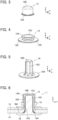
FIG. 3 is a perspective view showing a first contact used in the first connector inEmbodiment 1. -
FIG. 4 is a perspective view showing a first retention member used in the first connector inEmbodiment 1. -
FIG. 5 is a perspective view showing a first insulator used in the first connector inEmbodiment 1. -
FIG. 6 is a partial cross-sectional view showing the first connector inEmbodiment 1. -
FIG. 7 is an assembly view of the second connector inEmbodiment 1. -
FIG. 8 is a perspective view showing a second contact used in the second connector inEmbodiment 1. -
FIG. 9 is a perspective view showing a magnet of a second retention member used in the second connector inEmbodiment 1. -
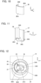
FIG. 10 is a perspective view showing a retention plate of the second retention member used in the second connector inEmbodiment 1. -
FIG. 11 is a perspective view showing the second retention member used in the second connector inEmbodiment 1. -
FIG. 12 is a perspective view showing the second connector inEmbodiment 1 when viewed from an obliquely lower position. -
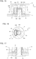
FIG. 13 is a partial cross-sectional view showing the second connector inEmbodiment 1. -
FIG. 14 is a partial cross-sectional view showing the first connector and the second connector that are aligned with respect to each other in the connector assembly according toEmbodiment 1. -
FIG. 15 is a partial cross-sectional view showing the second connector being in a fitting start position with respect to the first connector in the connector assembly according toEmbodiment 1. -
FIG. 16 is a cross-sectional view taken along line A-A inFIG. 15 . -
FIG. 17 is a partial cross-sectional view taken along line B-B inFIG. 16 . -
FIG. 18 is a partial cross-sectional view showing the second connector being in a fitting completed position with respect to the first connector in the connector assembly according toEmbodiment 1. -
FIG. 19 is a cross-sectional view taken along line C-C inFIG. 18 . -
FIG. 20 is a partial cross-sectional view taken along line D-D inFIG. 19 . -
FIG. 21 is a perspective view showing a fitted state between the first connector and the second connector of the connector assembly according toEmbodiment 1. -
FIG. 22 is a bottom view of the second connector in the process of production of the connector assembly according toEmbodiment 1. -
FIG. 23 is a perspective view showing a non-fitted state between a first connector and a second connector of a connector assembly according toEmbodiment 2. -
FIG. 24 is an assembly view of the second connector inEmbodiment 2. -
FIG. 25 is a perspective view showing a magnet of a second retention member used in the second connector inEmbodiment 2. -
FIG. 26 is a perspective view showing a retention plate of the second retention member used in the second connector inEmbodiment 2. -
FIG. 27 is a partial cross-sectional view showing the second connector inEmbodiment 2. -
FIG. 28 is a partial bottom view showing the second connector inEmbodiment 2. -
FIG. 29 is a partial cross-sectional view showing the first connector and the second connector that are aligned with respect to each other in the connector assembly according toEmbodiment 2. -
FIG. 30 is a partial cross-sectional view showing the second connector being in a fitting start position with respect to the first connector in the connector assembly according toEmbodiment 2. -
FIG. 31 is a cross-sectional view taken along line E-E inFIG. 30 . -
FIG. 32 is a partial cross-sectional view showing the second connector being in a fitting completed position with respect to the first connector in the connector assembly according toEmbodiment 2. -
FIG. 33 is a cross-sectional view taken along line F-F inFIG. 32 . -
FIG. 34 is a bottom view of the second connector in the process of production of the connector assembly according toEmbodiment 2. -
FIG. 35 is a perspective view showing a non-fitted state between a first connector and a second connector in a conventional connector. -
FIG. 36 is a perspective view of the first connector in the conventional connector when viewed from an obliquely lower position. - Embodiments of the present invention are described below based on the accompanying drawings.
-
FIG. 1 shows a connector assembly according toEmbodiment 1. The connector assembly includes afirst connector 11 and asecond connector 21 to be fitted to thefirst connector 11 along a fitting direction. - The
first connector 11 is used as, for example, a garment-side connector for connecting a wearable device and includes sixfirst contacts 12 protruding toward thesecond connector 21. The sixfirst contacts 12 are aligned in two rows and attached to a sheet typeconductive member 14 via areinforcement sheet 13. - For convenience, the
reinforcement sheet 13 and the sheet typeconductive member 14 are defined as extending along an XY plane, the direction in which thefirst contacts 12 are aligned in two rows is referred to as "Y direction," and the direction from thefirst connector 11 toward thesecond connector 21 is referred to as "+Z direction." The Z direction is the fitting direction in which thefirst connector 11 and thesecond connector 21 are fitted together. -
FIG. 2 shows an assembly view of thefirst connector 11. Sixfirst retention members 15 are disposed on the -Z direction side of the sixfirst contacts 12, thereinforcement sheet 13 and the sheet typeconductive member 14 are sequentially disposed on the -Z direction side of the sixfirst retention members 15, and sixfirst insulators 16 are disposed on the -Z direction side of the sheet typeconductive member 14. - The sheet type
conductive member 14 includes an insulatingsheet body 14A, six through-holes 14B formed in thesheet body 14A and corresponding to the sixfirst contacts 12, and sixflexible conductors 14C exposed around the corresponding through-holes 14B at least on the surface of thesheet body 14A on the +Z direction side. As thesheet body 14A, for example, cloth or knitted fabric of a garment may be used, and theflexible conductors 14C can be formed by embroidering thesheet body 14A with an embroidery thread constituted of a conductive thread. - The
reinforcement sheet 13 is used to reinforce thesheet body 14A of the sheet typeconductive member 14 on which thefirst connector 11 is mounted. Thereinforcement sheet 13 is made of an insulating material and has six through-holes 13A corresponding to the sixfirst contacts 12. - The sheet type
conductive member 14 and thereinforcement sheet 13 have flexibility. - As shown in
FIG. 3 , thefirst contact 12 is formed of an electrically conductive material such as metal, has a tubular shape, specifically a cylindrical shape, extending in the Z direction, and is provided in its inside with arecess portion 12A opening in the -Z direction. Thefirst contact 12 is provided at its upper portion with afirst contact portion 12B having a circular flat shape extending along an XY plane and facing in the +Z direction. - As shown in
FIG. 4 , thefirst retention member 15 is formed of a magnetic body and includes atubular portion 15A extending in the Z direction and aflange 15B extending out of thetubular portion 15A from the -Z directional end of thetubular portion 15A along an XY plane. Thetubular portion 15A is provided with a through-hole 15C penetrating thefirst retention member 15 in the Z direction. The through-hole 15C has an inner diameter substantially the same as the inner diameter of therecess portion 12A of thefirst contact 12. - The -Z directional end of the
tubular portion 15A in contact with theflange 15B is provided with anannular groove 15D along the outer periphery of thetubular portion 15A. - As shown in
FIG. 5 , thefirst insulator 16 is formed of, for instance, insulating resin and includes abase portion 16A of disc shape extending in an XY plane and aprojection 16B projecting in the +Z direction from the center of thebase portion 16A. Theprojection 16B is provided with a plurality ofribs 16C radially protruding and extending in the Z direction. Theprojection 16B is sized to be able to compress the sheet typeconductive member 14 in the thickness direction of the sheet typeconductive member 14 when being inserted into the through-hole 15C of thetubular portion 15A of thefirst retention member 15 and therecess portion 12A of thefirst contact 12 while pushing the sheet typeconductive member 14 thereinto. -
FIG. 6 shows a cross-sectional view corresponding to onefirst contact 12 of thefirst connector 11 that is assembled using the thus configuredfirst contacts 12,first retention members 15,reinforcement sheet 13, sheet typeconductive member 14, andfirst insulators 16. - The
reinforcement sheet 13 is stacked on the sheet typeconductive member 14 with the through-holes first retention member 15 and thefirst contact 12 are sequentially disposed in a coaxial manner on thereinforcement sheet 13 to be aligned with the through-hole 13A; in this state, theprojection 16B of thefirst insulator 16 is pushed in the +Z direction from the -Z direction of the sheet typeconductive member 14 through the through-hole 14B of the sheet typeconductive member 14. Theprojection 16B is sequentially inserted into the through-hole 15C of thefirst retention member 15 and therecess portion 12A of thefirst contact 12 while pushing a part of the sheet typeconductive member 14 situated around the through-hole 14B thereinto. - Consequently, the sheet type
conductive member 14 is sandwiched between therib 16C of theprojection 16B and the inner surface of the through-hole 15C of thefirst retention member 15 and between therib 16C of theprojection 16B and the inner surface of therecess portion 12A of thefirst contact 12 and compressed in a direction along an XY plane. As a result, theflexible conductor 14C exposed on the surface of the sheet typeconductive member 14 makes contact with the inner surface of therecess portion 12A at a predetermined contact pressure, whereby thefirst contact 12 is electrically connected to theflexible conductor 14C. - In addition, the
first retention member 15 and thefirst contact 12 are joined together in the Z direction via theprojection 16B of thefirst insulator 16 and the sheet typeconductive member 14. - The
base portion 16A of thefirst insulator 16 comes into contact with the rear surface, on the -Z direction side, of the sheet typeconductive member 14. - The six
first contacts 12 of thefirst connector 11 are all electrically connected to the correspondingflexible conductors 14C and also joined to the correspondingfirst retention members 15 by the connection structure illustrated inFIG. 6 . -
FIG. 7 shows an assembly view of thesecond connector 21. Sixsecond contacts 23 are disposed on the -Z direction side of asubstrate 22, sixsecond insulators 24 are disposed on the -Z direction side of the sixsecond contacts 23, sixmagnets 25 are disposed on the -Z direction side of the sixsecond insulators 24, and sixretention plates 26 are disposed on the -Z direction side of the sixmagnets 25. The sixsecond contacts 23 are arranged to correspond in position to the sixfirst contacts 12 of thefirst connector 11. - As shown in
FIG. 8 , thesecond contact 23 is constituted of a so-called pogo pin and includes abarrel 23A extending in the Z direction and aplunger 23B disposed to be elastically movable forward and backward in the Z direction within thebarrel 23A. More specifically, a spring member (not shown) is disposed inside thebarrel 23A and imparts an elastic force acting in the -Z direction to theplunger 23B. Theplunger 23B is provided at its -Z directional end with asecond contact portion 23C of pin shape that faces in the -Z direction. - As shown in
FIG. 9 , themagnet 25 has the shape of a curved plate being curved in an XY plane and extending in the Z direction and is magnetized such that magnetic field lines act mainly in the +Y direction. The curved shape of themagnet 25 in an XY plane has a curvature that allows the curved shape to follow an outer peripheral portion of thetubular portion 15A of thefirst retention member 15 of thefirst connector 11. - As shown in
FIG. 10 , theretention plate 26 is formed of a magnetic body and includes acurved portion 26A being curved in an XY plane and extending in the Z direction and a pair offlat portions 26B extending in the Z direction at the opposite ends of the curved shape of thecurved portion 26A. Thecurved portion 26A is curved to follow an outer peripheral portion of themagnet 25, and theretention plate 26 has such a shape as to cover the curved surface facing in the -Y direction and the +X and -X directional lateral surfaces of themagnet 25. - As shown in
FIG. 11 , in the state where themagnet 25 is disposed on the inner side of theretention plate 26 and the curved surface facing in the -Y direction and the +X and -X directional lateral surfaces of themagnet 25 are covered with theretention plate 26, theretention plate 26 formed of a magnetic body is attracted by and attached to themagnet 25 by the magnetic force. Themagnet 25 and theretention plate 26 as above together form asecond retention member 27. - It should be noted that the -Z directional end of the
magnet 25 protrudes in the - Z direction out of the -Z directional end of theretention plate 26. - The pair of
flat portions 26B of theretention plate 26 are separately provided at their -Z directional ends with a pair ofprotrusion portions 26C protruding along the surfaces of theflat portions 26B on the +Y direction side. Specifically, the pair ofprotrusion portions 26C each protrude in a direction toward the center of the curved shape of thecurved portion 26A. Eachprotrusion portion 26C has a height dimension in the Z direction slightly smaller than the width in the Z direction of theannular groove 15D of thefirst retention member 15 shown inFIG. 4 and therefore can be fitted in theannular groove 15D of thefirst retention member 15. - A lock receiving portion of the
first connector 11 is formed by theannular groove 15D of thefirst retention member 15 shown inFIG. 4 , and a lock portion of thesecond connector 21 is formed by the pair ofprotrusion portions 26C of thesecond retention member 27 shown inFIG. 11 . The pair ofprotrusion portions 26C of thesecond retention member 27 are fitted in theannular groove 15D of thefirst retention member 15 along the Y direction (predetermined direction), thereby locking the fitting between thefirst connector 11 and thesecond connector 21. -
FIGS. 12 and13 show a perspective view and a cross-sectional view corresponding to onesecond contact 23 of thesecond connector 21. Thesecond insulator 24 is disposed on the -Z direction side of thesubstrate 22. Thesecond insulator 24 has a cylindrical outer shape and is provided in its inside with a firstcontact accommodating portion 24A of recess shape that opens in the -Z direction and a second retentionmember accommodating portion 24B of recess shape that opens in the -Z direction. The firstcontact accommodating portion 24A and the second retentionmember accommodating portion 24B are disposed to be adjacent to each other and communicate with each other within thesecond insulator 24. - Specifically, the first contact accommodating portion 24Ahas an elliptical shape elongated in the Y direction (predetermined direction) when viewed from the -Z direction, and the second retention
member accommodating portion 24B is disposed to be adjacent to the -Y directional end of the firstcontact accommodating portion 24A. Since the firstcontact accommodating portion 24A has an elliptical shape elongated in the Y direction, thesecond connector 21 is slidable in the Y direction (predetermined direction) with respect to thefirst connector 11 with thefirst contact 12 of thefirst connector 11 being accommodated in the firstcontact accommodating portion 24A from the -Z direction. - In addition, the bottom of the first
contact accommodating portion 24A is provided with a secondcontact accommodating hole 24C that is situated on the central axis, which extends in the Z direction, of thesecond insulator 24 having a cylindrical outer shape and that penetrates thesecond insulator 24 in the Z direction. - A
wiring portion 22A is formed on the rear surface of thesubstrate 22 on the -Z direction side as shown inFIG. 12 . Thesecond contact 23 is mounted on thesubstrate 22 so as to be connected to thewiring portion 22A and accommodated in the secondcontact accommodating hole 24C of thesecond insulator 24. As shown inFIGS. 12 and13 , theplunger 23B of thesecond contact 23 protrudes within the firstcontact accommodating portion 24A of thesecond insulator 24 through the secondcontact accommodating hole 24C, and thesecond contact portion 23C formed at the -Z directional end of theplunger 23B is exposed within the firstcontact accommodating portion 24A. - Each of the six
second insulators 24 of thesecond connector 21 is disposed on the -Z direction side of thesubstrate 22, thesecond contact 23 is accommodated in the secondcontact accommodating hole 24C of the correspondingsecond insulator 24, and thesecond retention member 27 is accommodated in the second retentionmember accommodating portion 24B of the correspondingsecond insulator 24, as shown inFIG. 13 . In the state where theretention plate 26 is bonded and fixed to the inner peripheral surface of the second retentionmember accommodating portion 24B of thesecond insulator 24 and the +Z directional end of themagnet 25 is bonded and fixed to the bottom, on the +Z direction side, of the second retentionmember accommodating portion 24B of thesecond insulator 24, theretention plate 26 formed of a magnetic body is attracted by and attached to themagnet 25 by the magnetic force. - It should be noted that the orientations of the six
second insulators 24 in an XY plane are uniform; specifically, in eachsecond insulator 24, the firstcontact accommodating portion 24A has an elliptical shape elongated in the Y direction, and the second retentionmember accommodating portion 24B is disposed to be adjacent to the - Y directional end of the firstcontact accommodating portion 24A. - To fit the
second connector 21 to thefirst connector 11, as shown inFIG. 14 , thesecond connector 21 is placed on the +Z direction side of thefirst connector 11, and thefirst connector 11 and thesecond connector 21 are positioned with respect to each other such that the +Y directional end of the firstcontact accommodating portion 24A of elliptical shape elongated in the Y direction of thesecond insulator 24 is aligned with the +Z direction side of the +Y directional end of thefirst contact 12. - In this state, the
second connector 21 is relatively moved in the -Z direction toward thefirst connector 11, whereby thefirst contact 12 of thefirst connector 11 is accommodated into the firstcontact accommodating portion 24A of thesecond insulator 24 of thesecond connector 21 as shown inFIG. 15 . - When the
second connector 21 is relatively moved in the -Z direction until the - Z directional end of themagnet 25 of thesecond retention member 27 of thesecond connector 21 abuts on theflange 15B of thefirst retention member 15 of thefirst connector 11, thesecond contact portion 23C formed on theplunger 23B of thesecond contact 23 of thesecond connector 21 makes contact with thefirst contact portion 12B in a flat shape of thefirst contact 12 of thefirst connector 11, so that a part of theplunger 23B is elastically retracted into thebarrel 23A. Thefirst contact portion 12B thus contacts thesecond contact portion 23C in the Z direction at a predetermined contact pressure, so that thefirst contact 12 and thesecond contact 23 are electrically connected together. - In addition, since the -Z directional end of the
magnet 25 of thesecond retention member 27 abuts on theflange 15B of thefirst retention member 15 formed of a magnetic body, themagnet 25 is attracted by and attached to theflange 15B by the magnetic force, thus maintaining the contacting state between thefirst contact portion 12B and thesecond contact portion 23C in the Z direction. - The position of the
second connector 21 with respect to thefirst connector 11 at this time is called a fitting start position P1. - Since the
second connector 21 is relatively moved in the -Z direction with the +Y directional end of the firstcontact accommodating portion 24A of thesecond insulator 24 being aligned with the +Y directional end of thefirst contact 12 in the Z direction, thefirst contact 12 is accommodated in a position offset to the +Y direction side within the firstcontact accommodating portion 24A of elliptical shape elongated in the Y direction, as shown inFIG. 16 . Thus, theplunger 23B of thesecond contact 23 is situated in an eccentric position with respect to the circularfirst contact portion 12B of thefirst contact 12. - Accordingly, a gap is formed between the -Y directional end of the
first contact 12 and thesecond retention member 27, so that thesecond connector 21 can be relatively moved in the -Z direction to the fitting start position P1 with no interference between theprotrusion portion 26C, which protrudes on the +Y direction side from the - Z directional end of theretention plate 26 of thesecond retention member 27, and thefirst contact 12 or thetubular portion 15A of thefirst retention member 15, as shown inFIG. 17 . - When the
second connector 21 is in the fitting start position P1 as shown inFIGS. 15 to 17 , thefirst contact 12 and thesecond contact 23 are electrically connected together because thefirst contact portion 12B contacts thesecond contact portion 23C in the Z direction at a predetermined contact pressure, and thesecond connector 21 is in the fitting start position P1 with respect to thefirst connector 11 only with the magnetic force acting between themagnet 25 of thesecond retention member 27 and theflange 15B of thefirst retention member 15. - Further, since the
first contact 12 and thesecond contact 23 are connected together with theplunger 23B of thesecond contact 23 being elastically retracted, a force acting in the direction of separating thefirst connector 11 and thesecond connector 21 from each other in the Z direction is exerted from thesecond contact 23. - Therefore, if an external force due to, for instance, impact acts between the
first connector 11 and thesecond connector 21 to move thesecond connector 21 in the +Z direction with respect to thefirst connector 11, the contact between thefirst contact 12 and thesecond contact 23 is destabilized, and this may lead to lower reliability of the electric connection. - To cope with it, the
second connector 21 is relatively slid in the +Y direction with respect to thefirst connector 11 until thesecond retention member 27 of thesecond connector 21 makes contact with or closely approaches thetubular portion 15A of thefirst retention member 15 of thefirst connector 11, as shown inFIG. 18 . Specifically, thesecond connector 21 is slid with respect to thefirst connector 11 until themagnet 25 of thesecond retention member 27 makes contact with or closely approaches the -Y directional end of thetubular portion 15A of thefirst retention member 15. - At this time, since the
first contact portion 12B of thefirst contact 12 of thefirst connector 11 has a flat shape extending along an XY plane, thesecond contact portion 23C of thesecond contact 23 slides in the +Y direction with respect to thefirst contact portion 12B while maintaining contact with thefirst contact portion 12B of thefirst contact 12. Thus, the electric connection between thefirst contact 12 and thesecond contact 23 is maintained. - Besides, even when dirt or foreign matter is attached to a surface of at least one of the
first contact portion 12B of thefirst contact 12 or thesecond contact portion 23C of thesecond contact 23, sliding of thesecond contact portion 23C in the +Y direction with respect to thefirst contact portion 12B generates a wiping effect, and this effectively removes such dirt or foreign matter, thus improving contact stability between thefirst contact portion 12B and thesecond contact portion 23C. - When the
second connector 21 is slid in the +Y direction with respect to thefirst connector 11, as shown inFIG. 19 , thefirst contact 12 is positioned on the -Y direction side within the firstcontact accommodating portion 24A of elliptical shape elongated in the Y direction, so that theplunger 23B of thesecond contact 23 is situated in the center of the circularfirst contact portion 12B of thefirst contact 12. - In addition, the pair of
protrusion portions 26C protruding on the +Y direction side from the -Z directional ends of the pair offlat portions 26B of theretention plate 26 of thesecond retention member 27 are fitted into theannular groove 15D formed in thetubular portion 15A of thefirst retention member 15, as shown inFIG. 20 . - In other words, the lock portion formed by the pair of
protrusion portions 26C is fitted in the lock receiving portion formed by theannular groove 15D, whereby thesecond connector 21 is prevented from moving in the +Z direction with respect to thefirst connector 11, thus maintaining the electrically connected state between thefirst contact 12 and thesecond contact 23 through the contact between thefirst contact portion 12B and thesecond contact portion 23C. - The
second connector 21 is thus fitted to thefirst connector 11. - The position of the
second connector 21 with respect to thefirst connector 11 at this time is called a fitting completed position P2. - Since the
magnet 25 of thesecond retention member 27 makes contact with or closely approaches the -Y directional end of thetubular portion 15A of thefirst retention member 15, the magnetic force acts between themagnet 25 and thetubular portion 15A formed of a magnetic body to attract them to each other in the Y direction, and this keeps thesecond connector 21 in the fitting completed position P2 with respect to thefirst connector 11. - Owing to the
second connector 21 being in the fitting completed position P2, thesecond contact 23 of thesecond connector 21 is electrically connected to the correspondingflexible conductor 14C of the sheet typeconductive member 14 via thefirst contact 12 of thefirst connector 11. - Since the six
second insulators 24 of thesecond connector 21 are disposed on the -Z direction side of thesubstrate 22 with their orientations being uniform in an XY plane, when thesubstrate 22 is relatively moved in the -Z direction toward thefirst connector 11, the state where thesecond connector 21 is in the fitting start position P1 with respect to thefirst connector 11 is formed in each of the sixsecond insulators 24, and further, when thesubstrate 22 is relatively slid in the +Y direction with respect to thefirst connector 11, the state where thesecond connector 21 is in the fitting completed position P2 with respect to thefirst connector 11 is formed in each of the sixsecond insulators 24. - Thus, the fitted state is established between the
first connector 11 and thesecond connector 21 as shown inFIG. 21 . - Since the six
second insulators 24 of thesecond connector 21 need to be uniformly oriented in an XY plane, for instance, the sixsecond insulators 24 may be formed by resin molding to be joined together via a joint member C as shown inFIG. 22 . The sixsecond insulators 24 are molded to be joined while keeping their positional relation that is required when disposed on thesubstrate 22, and the sixsecond contacts 23 mounted on thesubstrate 22 are accommodated into the sixsecond insulators 24 that are still joined, whereby the sixsecond insulators 24 are disposed on thesubstrate 22. Subsequently, thesecond retention members 27 are accommodated into the correspondingsecond insulators 24. - Thereafter, the joint member C is cut and removed from the six
second insulators 24. Thus, thesecond connector 21 can be fabricated with thesecond insulators 24 being in a uniform orientation. -
FIG. 23 shows a connector assembly according toEmbodiment 2. The connector assembly is configured such that in the connector assembly according toEmbodiment 1, afirst connector 11 is fitted to asecond connector 31 in place of thesecond connector 21, and thefirst connector 11 is the same as that used inEmbodiment 1. -
FIG. 24 shows an assembly view of thesecond connector 31. Sixsecond contacts 23 are disposed on the -Z direction side of asubstrate 22, sixsecond insulators 34 are disposed on the -Z direction side of the sixsecond contacts 23, sixmagnets 35 are disposed on the -Z direction side of the sixsecond insulators 34, and sixretention plates 36 are disposed on the -Z direction side of the sixmagnets 35. - The
substrate 22 and the sixsecond contacts 23 are the same as those used inEmbodiment 1. - As shown in
FIG. 25 , themagnet 35 has a cylindrical shape extending in the Z direction and is provided in its inside with a through-hole 35A that penetrates themagnet 35 in the Z direction. Themagnet 35 is magnetized such that magnetic field lines act mainly in the +Y direction. - As shown in
FIG. 26 , theretention plate 36 is formed of a magnetic body and constituted of a ring member extending in a flat plate form along an XY plane. Theretention plate 36 is provided with a through-hole 36A that penetrates theretention plate 36 in the Z direction. -
FIG. 27 shows a cross-sectional view corresponding to onesecond contact 23 of thesecond connector 31. Thesecond insulator 34 is disposed on the -Z direction side of thesubstrate 22. Thesecond insulator 34 has a cylindrical outer shape and is provided in its inside with a firstcontact accommodating portion 34A of recess shape that opens in the -Z direction and a second retentionmember accommodating portion 34B of recess shape that opens in the -Z direction. The second retentionmember accommodating portion 34B is situated outside the firstcontact accommodating portion 34A to surround the firstcontact accommodating portion 34A and communicates with the firstcontact accommodating portion 34A. - The bottom of the first
contact accommodating portion 34A is provided with a secondcontact accommodating hole 34C that is situated on the central axis, which extends in the Z direction, of thesecond insulator 34 having a cylindrical outer shape and that penetrates thesecond insulator 34 in the Z direction. - The
second contact 23 mounted on thesubstrate 22 is accommodated in the secondcontact accommodating hole 34C of thesecond insulator 34, theplunger 23B of thesecond contact 23 protrudes within the firstcontact accommodating portion 34A of thesecond insulator 34 through the secondcontact accommodating hole 34C, and thesecond contact portion 23C formed at the -Z directional end of theplunger 23B is exposed within the firstcontact accommodating portion 34A. - The
cylindrical magnet 35 is accommodated in the second retentionmember accommodating portion 34B of thesecond insulator 34. In addition, theretention plate 36 constituted of a ring member formed of a magnetic body is press-fitted or bonded and thereby fixed to the -Z directional open end of the second retentionmember accommodating portion 34B of thesecond insulator 34, and attracted by and attached to the -Z directional end of themagnet 35 by the magnetic force. Themagnet 35 and theretention plate 36 as above together form asecond retention member 37. - The
retention plate 36 constituted of a ring member has the same outer diameter as the outer diameter of thecylindrical magnet 35, and the through-hole 36A of theretention plate 36 has an inner diameter smaller than the inner diameter of the through-hole 35A of themagnet 35, so that a step D1 is formed between the inner surface of the through-hole 36A of theretention plate 36 and the inner surface of the through-hole 35A of themagnet 35, and an edge portion of the through-hole 36A of theretention plate 36 protrudes inside the through-hole 35A of themagnet 35, as shown inFIG. 27 . Theretention plate 36 has a thickness in the Z direction slightly smaller than the width in the Z direction of theannular groove 15D of thefirst retention member 15 shown inFIG. 4 , so that the edge portion of the through-hole 36A of theretention plate 36 that protrudes inside the through-hole 35A of themagnet 35 can be fitted in theannular groove 15D of thefirst retention member 15. - The through-
hole 36A of theretention plate 36 is sized to allow thefirst contact 12 and thetubular portion 15A of thefirst retention member 15 to pass therethrough in the Z direction. - As shown in
FIG. 28 , the first contact accommodating portion 34Ahas an elliptical shape elongated in the Y direction (predetermined direction) when viewed from the -Z direction. Accordingly, thesecond connector 31 is slidable in the Y direction (predetermined direction) with respect to thefirst connector 11 with thefirst contact 12 of thefirst connector 11 being accommodated in the firstcontact accommodating portion 34A from the -Z direction. - The
second retention member 37 is situated in an eccentric position in the +Y direction with respect to thesecond insulator 34 having a cylindrical outer shape. - Each of the six
second insulators 34 of thesecond connector 31 is disposed on the -Z direction side of thesubstrate 22, thesecond contact 23 is accommodated in the secondcontact accommodating hole 34C of the correspondingsecond insulator 34, and thesecond retention member 37 is accommodated in the second retentionmember accommodating portion 34B of the correspondingsecond insulator 34, as shown inFIG. 27 . - It should be noted that the orientations of the six
second insulators 34 in an XY plane are uniform, and in eachsecond insulator 34, the firstcontact accommodating portion 34A has an elliptical shape elongated in the Y direction as shown inFIG. 28 . - To fit the
second connector 31 to thefirst connector 11, as shown inFIG. 29 , thesecond connector 31 is placed on the +Z direction side of thefirst connector 11, and thefirst connector 11 and thesecond connector 31 are positioned with respect to each other such that the +Y directional end of the firstcontact accommodating portion 34A of elliptical shape elongated in the Y direction of thesecond insulator 34 is aligned with the +Z direction side of the +Y directional end of thefirst contact 12. - In this state, the
second connector 31 is relatively moved in the -Z direction toward thefirst connector 11, whereby thefirst contact 12 of thefirst connector 11 is accommodated into the firstcontact accommodating portion 34A of thesecond insulator 34 of thesecond connector 31 as shown inFIG. 30 . - When the
second connector 31 is relatively moved in the -Z direction until theretention plate 36 of thesecond retention member 37 of thesecond connector 31 abuts on theflange 15B of thefirst retention member 15 of thefirst connector 11, thesecond contact portion 23C formed on theplunger 23B of thesecond contact 23 of thesecond connector 31 makes contact with thefirst contact portion 12B in a flat shape of thefirst contact 12 of thefirst connector 11, so that a part of theplunger 23B is elastically retracted into thebarrel 23A. Thefirst contact portion 12B thus contacts thesecond contact portion 23C in the Z direction at a predetermined contact pressure, so that thefirst contact 12 and thesecond contact 23 are electrically connected together. - In addition, since the
retention plate 36 disposed on the -Z directional end of themagnet 35 of thesecond retention member 37 abuts on theflange 15B of thefirst retention member 15 formed of a magnetic body, themagnet 35 is attracted by and attached to theflange 15B by the magnetic force via theretention plate 36, thus maintaining the contacting state between thefirst contact portion 12B and thesecond contact portion 23C in the Z direction. - The position of the
second connector 31 with respect to thefirst connector 11 at this time is called a fitting start position P1. - Since the
second connector 31 is relatively moved in the -Z direction with the +Y directional end of the firstcontact accommodating portion 34A of thesecond insulator 34 being aligned with the +Y directional end of thefirst contact 12 in the Z direction, thefirst contact 12 is accommodated in a position offset to the +Y direction side within the firstcontact accommodating portion 34A of elliptical shape elongated in the Y direction as shown inFIG. 31 . - Accordingly, a gap is formed between the -Y directional end of the
first contact 12 and the -Y directional end of the interior of the firstcontact accommodating portion 34A, so that thesecond connector 31 can be relatively moved in the -Z direction to the fitting start position P1 with no interference between the edge portion of the through-hole 36A of theretention plate 36 of thesecond retention member 37 and thefirst contact 12 or thetubular portion 15A of thefirst retention member 15 as shown inFIG. 30 . - When the
second connector 31 is in the fitting start position P1 as shown inFIG. 30 , thefirst contact 12 and thesecond contact 23 are electrically connected together because thefirst contact portion 12B contacts thesecond contact portion 23C in the Z direction at a predetermined contact pressure, and thesecond connector 31 is in the fitting start position P1 with respect to thefirst connector 11 only with the magnetic force acting between themagnet 35 of thesecond retention member 37 and theflange 15B of thefirst retention member 15. - Further, since the
first contact 12 and thesecond contact 23 are connected together with theplunger 23B of thesecond contact 23 being elastically retracted, a force acting in the direction of separating thefirst connector 11 and thesecond connector 31 from each other in the Z direction is exerted from thesecond contact 23. - Therefore, if an external force due to, for instance, impact acts between the
first connector 11 and thesecond connector 31 to move thesecond connector 31 in the +Z direction with respect to thefirst connector 11, the contact between thefirst contact 12 and thesecond contact 23 is destabilized, and this may lead to lower reliability of the electric connection. - To cope with it, the
second connector 31 is relatively slid in the +Y direction with respect to thefirst connector 11 until thesecond retention member 37 of thesecond connector 31 makes contact with or closely approaches thetubular portion 15A of thefirst retention member 15 of thefirst connector 11, as shown inFIG. 32 . Specifically, thesecond connector 31 is slid with respect to thefirst connector 11 until the inner surface of themagnet 35 of thesecond retention member 37 makes contact with or closely approaches the -Y directional end of thetubular portion 15A of thefirst retention member 15. - At this time, since the
first contact portion 12B of thefirst contact 12 of thefirst connector 11 has a flat shape extending along an XY plane, thesecond contact portion 23C of thesecond contact 23 slides in the +Y direction with respect to thefirst contact portion 12B while maintaining contact with thefirst contact portion 12B of thefirst contact 12. Thus, the electric connection between thefirst contact 12 and thesecond contact 23 is maintained. - In addition, a wiping effect is generated also in
Embodiment 2 due to sliding of thesecond contact portion 23C in the +Y direction with respect to thefirst contact portion 12B; therefore, even when dirt or foreign matter is attached to a surface of at least one of thefirst contact portion 12B of thefirst contact 12 or thesecond contact portion 23C of thesecond contact 23, such dirt or foreign matter is effectively removed, thus improving contact stability between thefirst contact portion 12B and thesecond contact portion 23C. - When the
second connector 31 is slid in the +Y direction with respect to thefirst connector 11, thefirst contact 12 is positioned on the -Y direction side within the firstcontact accommodating portion 34A of elliptical shape elongated in the Y direction as shown inFIG. 33 , and anedge portion 36B at the -Y directional end of the through-hole 36A of theretention plate 36 that protrudes inside the through-hole 35A of themagnet 35 of thesecond retention member 37 is fitted into theannular groove 15D formed in thetubular portion 15A of thefirst retention member 15 as shown inFIG. 32 . - The
edge portion 36B at the -Y directional end of the through-hole 36A of theretention plate 36 forms a lock portion in thesecond connector 31. When this lock portion is fitted in the lock receiving portion, which is formed by theannular groove 15D, of thefirst connector 11 along the Y direction (predetermined direction), thesecond connector 31 is prevented from moving in the +Z direction with respect to thefirst connector 11, thus maintaining the electrically connected state between thefirst contact 12 and thesecond contact 23 through the contact between thefirst contact portion 12B and thesecond contact portion 23C. - The
second connector 31 is thus fitted to thefirst connector 11. - The position of the
second connector 31 with respect to thefirst connector 11 at this time is called a fitting completed position P2. - In addition, since the inner surface of the
magnet 35 of thesecond retention member 37 makes contact with or closely approaches the -Y directional end of thetubular portion 15A of thefirst retention member 15, the magnetic force acts between themagnet 35 and thetubular portion 15A formed of a magnetic body to attract them to each other in the Y direction, and this keeps thesecond connector 31 in the fitting completed position P2 with respect to thefirst connector 11. - Since the six
second insulators 34 of thesecond connector 31 are disposed on the -Z direction side of thesubstrate 22 with their orientations being uniform in an XY plane, when thesubstrate 22 is relatively moved in the -Z direction toward thefirst connector 11, the state where thesecond connector 31 is in the fitting start position P1 with respect to thefirst connector 11 is formed in each of the sixsecond insulators 34, and further, when thesubstrate 22 is relatively slid in the +Y direction with respect to thefirst connector 11, the state where thesecond connector 31 is in the fitting completed position P2 with respect to thefirst connector 11 is formed in each of the sixsecond insulators 34. - Thus, the fitted state is established between the
first connector 11 and thesecond connector 31. - Since the six
second insulators 34 of thesecond connector 31 need to be uniformly oriented in an XY plane, for instance, the sixsecond insulators 34 may be formed by resin molding to be joined together via a joint member C as shown inFIG. 34 . The sixsecond insulators 34 are molded to be joined while keeping their positional relation that is required when disposed on thesubstrate 22, and the sixsecond contacts 23 mounted on thesubstrate 22 are accommodated into the sixsecond insulators 34 that are still joined, whereby the sixsecond insulators 34 are disposed on thesubstrate 22. Subsequently, thesecond retention members 37 are accommodated into the correspondingsecond insulators 34. - Thereafter, the joint member C is cut and removed from the six
second insulators 34. Thus, thesecond connector 31 can be fabricated with thesecond insulators 34 being in a uniform orientation. - The
first contact 12 of thefirst connector 11 used inEmbodiments flexible conductor 14C of the sheet typeconductive member 14 inside therecess portion 12A formed therein, and is coaxially stacked on thefirst retention member 15 in the Z direction, thefirst retention member 15 being provided with theannular groove 15D serving as the lock receiving portion. This configuration makes it possible to arrange eachfirst contact 12 in a small space in an XY plane while forming the lock receiving portion for eachfirst contact 12. - The present invention is not configured such that the connection state between the plurality of
first contacts 12 and the plurality ofsecond contacts 23 is maintained by one set of the lock portion and the lock receiving portion, but configured such that thefirst retention member 15 having the lock receiving portion and thesecond retention member first contact 12 and thesecond contact 23 connected together. This configuration can prevent such defects as locking the fitting between thefirst connector 11 and thesecond connector first contacts 12 and a plurality of thesecond contacts 23, a part of the first andsecond contacts first contacts 12 and the plurality of thesecond contacts 23 can be reliably connected together. - It should be noted that the six
first contacts 12 of thefirst connector 11 are attached to the sheet typeconductive member 14 via thereinforcement sheet 13, and the sixfirst insulators 16 corresponding to the sixfirst contacts 12 are separate from one another. Accordingly, thefirst connector 11 has flexibility, and when cloth or knitted fabric of a garment is used as thesheet body 14A for instance, thefirst connector 11 can be attached to the garment without a decrease in wearing comfort. - Besides, while a circuit board having rigidity can be used as the
substrate 22 in thesecond connector substrate 22. In thesecond connector second insulators substrate 22 in the state of being separate from one another, the use of an FPC as thesubstrate 22 allows thesecond connector second connector first connector 11, the connector assembly that is bendable even after fitting can be formed, and this is suitable as a connector assembly for connecting a wearable device to so-called smart clothes that can acquire user's biological data such as the heart rate and the body temperature only by being worn by the user. - In
Embodiments first contact portion 12B of thefirst contact 12 has a flat shape extending along an XY plane, and thesecond contact portion 23C of thesecond contact 23 has a pin shape; however, even when thefirst contact portion 12B of thefirst contact 12 has a pin shape and thesecond contact portion 23C of thesecond contact 23 has a flat shape extending along an XY plane in an opposite fashion, the same effect can be obtained. - In
Embodiments first retention member 15 of thefirst connector 11 has the lock receiving portion (theannular groove 15D), and thesecond retention member second connector protrusion portion 26C, theedge portion 36B of the through-hole 36A of the retention plate 36) protruding in the Y direction; however, even when thefirst retention member 15 of thefirst connector 11 has the lock portion and thesecond retention member second connector - In
Embodiments first connector 11 has the sixfirst contacts 12, and thesecond connector second contacts 23; however, the numbers of thefirst contacts 12 and thesecond contacts 23 are each not limited to six, and it is sufficient that at least onefirst contact 12 and at least onesecond contact 23 are disposed in thefirst connector 11 and thesecond connector
Claims (12)
- A connector assembly in which a first connector (11) and a second connector (21, 31) are fitted together along a fitting direction,the first connector (11) including:a first contact (12) having electrical (12B) conductivity and having a first contact portion; anda first retention member (15) joined to the first contact, andthe second connector (21, 31) including:a second insulator (24, 34);a second contact (23) having electrical conductivity, retained by the second insulator, and having a second contact portion (23C) that faces the first contact portion of the first contact along the fitting direction; anda second retention member (27, 37) retained by the second insulator, the second retention member attracting and being attracted to the first retention member by a magnetic force,wherein one of the first contact portion (12B) and the second contact portion (23C) has a flat shape extending in a predetermined direction perpendicular to the fitting direction,one of the first retention member (15) and the second retention member (27, 37) has a lock portion (26C, 36B), and the other thereof has a lock receiving portion (15D) into which the lock portion is fitted from the predetermined direction,when the second connector is relatively moved to a predetermined fitting start position (P 1) with respect to the first connector along the fitting direction, the second retention member is attracted to the first retention member along the fitting direction, and the second contact portion makes contact with the first contact portion, whereby the second contact (23) is electrically connected to the first contact (12), andwhen the second connector is relatively slid from the predetermined fitting start position to a predetermined fitting completed position (P2) with respect to the first connector along the predetermined direction, the second contact portion is relatively slid with respect to the first contact portion in the predetermined direction while maintaining contact with the first contact portion, and the lock portion is fitted into the lock receiving portion, whereby the second connector (21, 31) is fitted to the first connector (11).
- The connector assembly according to claim 1,wherein the first connector includes a first insulator (16) having a projection (16B) projecting in the fitting direction,the first contact (12) has a tubular shape extending along the fitting direction and having a recess portion (12A) in its inside, and is provided with the first contact portion (12B) having the flat shape at one end of the first contact on a side closer to the second contact along the fitting direction,the first retention member (15) is disposed on a side of the other end of the first contact along the fitting direction and has a through-hole (15C) penetrating the first retention member in the fitting direction, andthe projection of the first insulator is sequentially inserted into the through-hole of the first retention member and the recess portion of the first contact while pushing, into the through-hole and the recess portion, a sheet type connection object (14) having a flexible conductor (14C) exposed at least on a surface of the sheet type connection object, whereby the first contact is electrically connected to the flexible conductor, and also the first retention member is joined to the first contact.
- The connector assembly according to claim 1 or 2,wherein the first retention member (15) is formed of a magnetic body and includes: a tubular portion (15A) extending along the fitting direction and provided with the through-hole; and a flange (15B) extending in the predetermined direction from an end of the tubular portion on an opposite side from the first contact, andwhen the second connector (21, 31) is in the predetermined fitting start position (P1), the second retention member (27, 37) is attracted to the flange of the first retention member along the fitting direction.
- The connector assembly according to claim 3,
wherein when the second connector is relatively slid from the predetermined fitting start position to the predetermined fitting completed position (P2) with respect to the first connector along the predetermined direction, the second retention member (27, 37) is attracted to an outer lateral surface of the tubular portion of the first retention member along the predetermined direction. - The connector assembly according to claim 3 or 4,wherein the first retention member (15) includes an annular groove (15D) formed along an outer periphery of the tubular portion (15A), andthe annular groove forms the lock receiving portion.
- The connector assembly according to any one of claims 3-5,
wherein the second retention member (27, 37) includes a magnet (25, 35) and a retention plate (26, 36) that is formed of a magnetic body and that is attracted by and attached to the magnet. - The connector assembly according to claim 6,wherein the magnet (25) has a shape of a curved plate that is curved to follow an outer peripheral portion of the tubular portion of the first retention member and that extends in the fitting direction,the retention plate (26) includes a curved portion (26A) that is curved to follow an outer peripheral portion of the magnet, a pair of flat portions (26B) extending in the fitting direction separately at opposite ends of a curved shape of the curved portion, and a pair of protrusion portions (26C) protruding in the predetermined direction separately from one ends of the pair of flat portions on a side closer to the first connector along the fitting direction, andthe pair of protrusion portions form the lock portion.
- The connector assembly according to claim 6,wherein the magnet (35) has a cylindrical shape which extends in the fitting direction and in which the tubular portion of the first retention member is inserted,the retention plate (36) is constituted of a ring member disposed at one end of the magnet on a side closer to the first connector along the fitting direction and having an inner diameter smaller than an inner diameter of the magnet, and includes an overhanging portion (36B) protruding in the predetermined direction toward a central axis of the magnet of the cylindrical shape, andthe overhanging portion forms the lock portion.
- The connector assembly according to any one of claim 1-8,the second insulator (24, 34) including:a second retention member accommodating portion (24B, 34B) of recess shape in which the second retention member is accommodated; anda first contact accommodating portion (24A, 34A) of recess shape in which at least a part of the first contact is accommodated,wherein the second retention member accommodating portion and the first contact accommodating portion communicate with each other and open in the fitting direction toward the first connector, andthe second contact (23) is retained by the second insulator such that at least a part of the second contact protrudes in the first contact accommodating portion.
- The connector assembly according to claim 9,
wherein the second contact (23) has a plunger (23B) disposed to be elastically movable forward and backward along the fitting direction, and the second contact portion (23C) disposed at a tip of the plunger protrudes in the first contact accommodating portion (24A, 34A). - The connector assembly according to claim 9 or 10,wherein the first contact accommodating portion (24A, 34A) has an elliptical shape elongated in the predetermined direction as viewed from the fitting direction, andwhen the second connector is in the predetermined fitting start position, the first contact is situated at one end of the first contact accommodating portion in the predetermined direction, and when the second connector is in the predetermined fitting completed position, the first contact is situated at the other end of the first contact accommodating portion in the predetermined direction.
- The connector assembly according to any one of claims 1-11,wherein the first connector (11) includes a plurality of the first contacts (12) and a plurality of the first retention members (15) corresponding to the plurality of the first contacts,the second connector (21,31) includes a plurality of the second insulators (24, 34), a plurality of the second contacts (23) retained separately by the plurality of the second insulators, and a plurality of the second retention members (27, 37) retained separately by the plurality of the second insulators and corresponding to the plurality of the second contacts,one of either the plurality of the first retention members (15) or the plurality of the second retention members (27, 37) has a plurality of the lock portions, and the other of either the plurality of the first retention members or the plurality of the second retention members has a plurality of the lock receiving portions, andwhen the second connector (21, 31) is in the predetermined fitting completed position and fitted to the first connector (11), the plurality of the second contacts are separately electrically connected to the plurality of the first contacts, and the plurality of the lock portions are separately fitted into the plurality of the lock receiving portions.
Applications Claiming Priority (1)
| Application Number | Priority Date | Filing Date | Title |
|---|---|---|---|
| JP2023105825A JP2025005598A (en) | 2023-06-28 | 2023-06-28 | Connector Assembly |
Publications (2)
| Publication Number | Publication Date |
|---|---|
| EP4485702A1 true EP4485702A1 (en) | 2025-01-01 |
| EP4485702B1 EP4485702B1 (en) | 2025-09-03 |
Family
ID=91193311
Family Applications (1)
| Application Number | Title | Priority Date | Filing Date |
|---|---|---|---|
| EP24175737.6A Active EP4485702B1 (en) | 2023-06-28 | 2024-05-14 | Connector assembly |
Country Status (4)
| Country | Link |
|---|---|
| US (1) | US20250007209A1 (en) |
| EP (1) | EP4485702B1 (en) |
| JP (1) | JP2025005598A (en) |
| CN (1) | CN119231248A (en) |
Families Citing this family (1)
| Publication number | Priority date | Publication date | Assignee | Title |
|---|---|---|---|---|
| TWI897736B (en) * | 2024-11-28 | 2025-09-11 | 寶成工業股份有限公司 | Quick-release installation module for shoemaking machines |
Citations (6)
| Publication number | Priority date | Publication date | Assignee | Title |
|---|---|---|---|---|
| US20160181728A1 (en) * | 2014-12-18 | 2016-06-23 | Japan Aviation Electronics Industry, Limited | Connector pair |
| US9437968B2 (en) * | 2013-12-27 | 2016-09-06 | Japan Aviation Electronics Industry, Limited | Magnet connector |
| US20180269606A1 (en) * | 2017-03-17 | 2018-09-20 | Japan Aviation Electronics Industry, Limited | Connector |
| JP2020030906A (en) | 2018-08-21 | 2020-02-27 | Smk株式会社 | Connector and connector assembly |
| EP3767753B1 (en) * | 2019-07-19 | 2021-10-27 | Japan Aviation Electronics Industry, Ltd. | Connector |
| CN114171975A (en) * | 2021-12-27 | 2022-03-11 | 优奈柯恩(北京)科技有限公司 | Socket, plug, connector component, data line and intelligent glasses |
-
2023
- 2023-06-28 JP JP2023105825A patent/JP2025005598A/en active Pending
-
2024
- 2024-04-25 CN CN202410508251.4A patent/CN119231248A/en active Pending
- 2024-05-14 EP EP24175737.6A patent/EP4485702B1/en active Active
- 2024-05-24 US US18/673,745 patent/US20250007209A1/en active Pending
Patent Citations (6)
| Publication number | Priority date | Publication date | Assignee | Title |
|---|---|---|---|---|
| US9437968B2 (en) * | 2013-12-27 | 2016-09-06 | Japan Aviation Electronics Industry, Limited | Magnet connector |
| US20160181728A1 (en) * | 2014-12-18 | 2016-06-23 | Japan Aviation Electronics Industry, Limited | Connector pair |
| US20180269606A1 (en) * | 2017-03-17 | 2018-09-20 | Japan Aviation Electronics Industry, Limited | Connector |
| JP2020030906A (en) | 2018-08-21 | 2020-02-27 | Smk株式会社 | Connector and connector assembly |
| EP3767753B1 (en) * | 2019-07-19 | 2021-10-27 | Japan Aviation Electronics Industry, Ltd. | Connector |
| CN114171975A (en) * | 2021-12-27 | 2022-03-11 | 优奈柯恩(北京)科技有限公司 | Socket, plug, connector component, data line and intelligent glasses |
Also Published As
| Publication number | Publication date |
|---|---|
| US20250007209A1 (en) | 2025-01-02 |
| JP2025005598A (en) | 2025-01-17 |
| CN119231248A (en) | 2024-12-31 |
| EP4485702B1 (en) | 2025-09-03 |
Similar Documents
| Publication | Publication Date | Title |
|---|---|---|
| US12027802B2 (en) | Connector | |
| US11658433B2 (en) | Connector | |
| US10199770B2 (en) | Connector | |
| US20220302617A1 (en) | Connector and connecting method | |
| EP3065226B1 (en) | Connector | |
| KR20200022352A (en) | Connector | |
| EP3226362A1 (en) | Slide connector | |
| CN107534234A (en) | Multipolar connector | |
| US9236695B2 (en) | Coaxial connector | |
| US11710922B2 (en) | Connector | |
| US20210057838A1 (en) | Connector and connecting method | |
| US12424774B2 (en) | Connector | |
| EP4485702B1 (en) | Connector assembly | |
| US20220149551A1 (en) | Electric connector for flat conductor | |
| US9859642B2 (en) | Connector and method for using connector | |
| US11183781B2 (en) | Connector | |
| US12230907B2 (en) | Electrical connector for connecting an electric wire to a flat flexible conductor and an electrical connector assembly therefor | |
| US10622744B2 (en) | Multipole connector | |
| US10122104B2 (en) | Connector for a flexible printed circuit | |
| US12068559B2 (en) | Connector for holding flexible printed circuit | |
| US10147993B2 (en) | Connecting device | |
| US12155139B2 (en) | Electrical connector | |
| JP2021114397A (en) | connector | |
| CN214379061U (en) | Electric connector and electric connector assembly | |
| CN117767046A (en) | Connector |
Legal Events
| Date | Code | Title | Description |
|---|---|---|---|
| PUAI | Public reference made under article 153(3) epc to a published international application that has entered the european phase |
Free format text: ORIGINAL CODE: 0009012 |
|
| STAA | Information on the status of an ep patent application or granted ep patent |
Free format text: STATUS: REQUEST FOR EXAMINATION WAS MADE |
|
| 17P | Request for examination filed |
Effective date: 20240514 |
|
| AK | Designated contracting states |
Kind code of ref document: A1 Designated state(s): AL AT BE BG CH CY CZ DE DK EE ES FI FR GB GR HR HU IE IS IT LI LT LU LV MC ME MK MT NL NO PL PT RO RS SE SI SK SM TR |
|
| GRAP | Despatch of communication of intention to grant a patent |
Free format text: ORIGINAL CODE: EPIDOSNIGR1 |
|
| STAA | Information on the status of an ep patent application or granted ep patent |
Free format text: STATUS: GRANT OF PATENT IS INTENDED |
|
| RIC1 | Information provided on ipc code assigned before grant |
Ipc: H01R 11/30 20060101ALN20250512BHEP Ipc: H01R 12/79 20110101ALN20250512BHEP Ipc: H01R 13/627 20060101ALN20250512BHEP Ipc: H01R 13/62 20060101ALI20250512BHEP Ipc: H01R 13/24 20060101AFI20250512BHEP |
|
| INTG | Intention to grant announced |
Effective date: 20250522 |
|
| RIN1 | Information on inventor provided before grant (corrected) |
Inventor name: KIMURA, AKIRA |
|
| GRAS | Grant fee paid |
Free format text: ORIGINAL CODE: EPIDOSNIGR3 |
|
| GRAA | (expected) grant |
Free format text: ORIGINAL CODE: 0009210 |
|
| STAA | Information on the status of an ep patent application or granted ep patent |
Free format text: STATUS: THE PATENT HAS BEEN GRANTED |
|
| AK | Designated contracting states |
Kind code of ref document: B1 Designated state(s): AL AT BE BG CH CY CZ DE DK EE ES FI FR GB GR HR HU IE IS IT LI LT LU LV MC ME MK MT NL NO PL PT RO RS SE SI SK SM TR |
|
| REG | Reference to a national code |
Ref country code: CH Ref legal event code: EP |
|
| REG | Reference to a national code |
Ref country code: DE Ref legal event code: R096 Ref document number: 602024000579 Country of ref document: DE |
|
| REG | Reference to a national code |
Ref country code: IE Ref legal event code: FG4D |
|
| REG | Reference to a national code |
Ref country code: NL Ref legal event code: MP Effective date: 20250903 |
|
| PG25 | Lapsed in a contracting state [announced via postgrant information from national office to epo] |
Ref country code: NO Free format text: LAPSE BECAUSE OF FAILURE TO SUBMIT A TRANSLATION OF THE DESCRIPTION OR TO PAY THE FEE WITHIN THE PRESCRIBED TIME-LIMIT Effective date: 20251203 |
|
| REG | Reference to a national code |
Ref country code: LT Ref legal event code: MG9D |
|
| PG25 | Lapsed in a contracting state [announced via postgrant information from national office to epo] |
Ref country code: FI Free format text: LAPSE BECAUSE OF FAILURE TO SUBMIT A TRANSLATION OF THE DESCRIPTION OR TO PAY THE FEE WITHIN THE PRESCRIBED TIME-LIMIT Effective date: 20250903 |
|
| PG25 | Lapsed in a contracting state [announced via postgrant information from national office to epo] |
Ref country code: HR Free format text: LAPSE BECAUSE OF FAILURE TO SUBMIT A TRANSLATION OF THE DESCRIPTION OR TO PAY THE FEE WITHIN THE PRESCRIBED TIME-LIMIT Effective date: 20250903 |
|
| PG25 | Lapsed in a contracting state [announced via postgrant information from national office to epo] |
Ref country code: GR Free format text: LAPSE BECAUSE OF FAILURE TO SUBMIT A TRANSLATION OF THE DESCRIPTION OR TO PAY THE FEE WITHIN THE PRESCRIBED TIME-LIMIT Effective date: 20251204 |
|
| PG25 | Lapsed in a contracting state [announced via postgrant information from national office to epo] |
Ref country code: SE Free format text: LAPSE BECAUSE OF FAILURE TO SUBMIT A TRANSLATION OF THE DESCRIPTION OR TO PAY THE FEE WITHIN THE PRESCRIBED TIME-LIMIT Effective date: 20250903 |
|
| PG25 | Lapsed in a contracting state [announced via postgrant information from national office to epo] |
Ref country code: LV Free format text: LAPSE BECAUSE OF FAILURE TO SUBMIT A TRANSLATION OF THE DESCRIPTION OR TO PAY THE FEE WITHIN THE PRESCRIBED TIME-LIMIT Effective date: 20250903 |
|
| PG25 | Lapsed in a contracting state [announced via postgrant information from national office to epo] |
Ref country code: PL Free format text: LAPSE BECAUSE OF FAILURE TO SUBMIT A TRANSLATION OF THE DESCRIPTION OR TO PAY THE FEE WITHIN THE PRESCRIBED TIME-LIMIT Effective date: 20250903 Ref country code: BG Free format text: LAPSE BECAUSE OF FAILURE TO SUBMIT A TRANSLATION OF THE DESCRIPTION OR TO PAY THE FEE WITHIN THE PRESCRIBED TIME-LIMIT Effective date: 20250903 |
|
| PG25 | Lapsed in a contracting state [announced via postgrant information from national office to epo] |
Ref country code: RS Free format text: LAPSE BECAUSE OF FAILURE TO SUBMIT A TRANSLATION OF THE DESCRIPTION OR TO PAY THE FEE WITHIN THE PRESCRIBED TIME-LIMIT Effective date: 20251203 |
|
| PG25 | Lapsed in a contracting state [announced via postgrant information from national office to epo] |
Ref country code: ES Free format text: LAPSE BECAUSE OF FAILURE TO SUBMIT A TRANSLATION OF THE DESCRIPTION OR TO PAY THE FEE WITHIN THE PRESCRIBED TIME-LIMIT Effective date: 20250903 |
|
| REG | Reference to a national code |
Ref country code: AT Ref legal event code: MK05 Ref document number: 1834309 Country of ref document: AT Kind code of ref document: T Effective date: 20250903 |
|
| PG25 | Lapsed in a contracting state [announced via postgrant information from national office to epo] |
Ref country code: NL Free format text: LAPSE BECAUSE OF FAILURE TO SUBMIT A TRANSLATION OF THE DESCRIPTION OR TO PAY THE FEE WITHIN THE PRESCRIBED TIME-LIMIT Effective date: 20250903 |
|
| PG25 | Lapsed in a contracting state [announced via postgrant information from national office to epo] |
Ref country code: SM Free format text: LAPSE BECAUSE OF FAILURE TO SUBMIT A TRANSLATION OF THE DESCRIPTION OR TO PAY THE FEE WITHIN THE PRESCRIBED TIME-LIMIT Effective date: 20250903 |
|
| PG25 | Lapsed in a contracting state [announced via postgrant information from national office to epo] |
Ref country code: AT Free format text: LAPSE BECAUSE OF FAILURE TO SUBMIT A TRANSLATION OF THE DESCRIPTION OR TO PAY THE FEE WITHIN THE PRESCRIBED TIME-LIMIT Effective date: 20250903 |
|
| PG25 | Lapsed in a contracting state [announced via postgrant information from national office to epo] |
Ref country code: IT Free format text: LAPSE BECAUSE OF FAILURE TO SUBMIT A TRANSLATION OF THE DESCRIPTION OR TO PAY THE FEE WITHIN THE PRESCRIBED TIME-LIMIT Effective date: 20250903 |
|
| PG25 | Lapsed in a contracting state [announced via postgrant information from national office to epo] |
Ref country code: IS Free format text: LAPSE BECAUSE OF FAILURE TO SUBMIT A TRANSLATION OF THE DESCRIPTION OR TO PAY THE FEE WITHIN THE PRESCRIBED TIME-LIMIT Effective date: 20260103 |
|
| PG25 | Lapsed in a contracting state [announced via postgrant information from national office to epo] |
Ref country code: PT Free format text: LAPSE BECAUSE OF FAILURE TO SUBMIT A TRANSLATION OF THE DESCRIPTION OR TO PAY THE FEE WITHIN THE PRESCRIBED TIME-LIMIT Effective date: 20260105 Ref country code: CZ Free format text: LAPSE BECAUSE OF FAILURE TO SUBMIT A TRANSLATION OF THE DESCRIPTION OR TO PAY THE FEE WITHIN THE PRESCRIBED TIME-LIMIT Effective date: 20250903 |
|
| PG25 | Lapsed in a contracting state [announced via postgrant information from national office to epo] |
Ref country code: EE Free format text: LAPSE BECAUSE OF FAILURE TO SUBMIT A TRANSLATION OF THE DESCRIPTION OR TO PAY THE FEE WITHIN THE PRESCRIBED TIME-LIMIT Effective date: 20250903 Ref country code: SK Free format text: LAPSE BECAUSE OF FAILURE TO SUBMIT A TRANSLATION OF THE DESCRIPTION OR TO PAY THE FEE WITHIN THE PRESCRIBED TIME-LIMIT Effective date: 20250903 |
|
| REG | Reference to a national code |
Ref country code: DE Ref legal event code: R097 Ref document number: 602024000579 Country of ref document: DE |
|
| PG25 | Lapsed in a contracting state [announced via postgrant information from national office to epo] |
Ref country code: LT Free format text: LAPSE BECAUSE OF FAILURE TO SUBMIT A TRANSLATION OF THE DESCRIPTION OR TO PAY THE FEE WITHIN THE PRESCRIBED TIME-LIMIT Effective date: 20250903 |
|
| PG25 | Lapsed in a contracting state [announced via postgrant information from national office to epo] |
Ref country code: DK Free format text: LAPSE BECAUSE OF FAILURE TO SUBMIT A TRANSLATION OF THE DESCRIPTION OR TO PAY THE FEE WITHIN THE PRESCRIBED TIME-LIMIT Effective date: 20250903 |
|
| PLBE | No opposition filed within time limit |
Free format text: ORIGINAL CODE: 0009261 |
|
| STAA | Information on the status of an ep patent application or granted ep patent |
Free format text: STATUS: NO OPPOSITION FILED WITHIN TIME LIMIT |
|
| PGFP | Annual fee paid to national office [announced via postgrant information from national office to epo] |
Ref country code: DE Payment date: 20260512 Year of fee payment: 3 |
|
| REG | Reference to a national code |
Ref country code: CH Ref legal event code: L10 Free format text: ST27 STATUS EVENT CODE: U-0-0-L10-L00 (AS PROVIDED BY THE NATIONAL OFFICE) Effective date: 20260715 |
|
| PGFP | Annual fee paid to national office [announced via postgrant information from national office to epo] |
Ref country code: FR Payment date: 20260526 Year of fee payment: 3 |
|
| 26N | No opposition filed |
Effective date: 20260604 |