EP4485701A1 - Connector and connector assembly - Google Patents
Connector and connector assembly Download PDFInfo
- Publication number
- EP4485701A1 EP4485701A1 EP24184254.1A EP24184254A EP4485701A1 EP 4485701 A1 EP4485701 A1 EP 4485701A1 EP 24184254 A EP24184254 A EP 24184254A EP 4485701 A1 EP4485701 A1 EP 4485701A1
- Authority
- EP
- European Patent Office
- Prior art keywords
- insulator
- outer conductor
- connector
- mating
- main body
- Prior art date
- Legal status (The legal status is an assumption and is not a legal conclusion. Google has not performed a legal analysis and makes no representation as to the accuracy of the status listed.)
- Pending
Links
Images








Classifications
-
- H—ELECTRICITY
- H01—ELECTRIC ELEMENTS
- H01R—ELECTRICALLY-CONDUCTIVE CONNECTIONS; STRUCTURAL ASSOCIATIONS OF A PLURALITY OF MUTUALLY-INSULATED ELECTRICAL CONNECTING ELEMENTS; COUPLING DEVICES; CURRENT COLLECTORS
- H01R12/00—Structural associations of a plurality of mutually-insulated electrical connecting elements, specially adapted for printed circuits, e.g. printed circuit boards [PCB], flat or ribbon cables, or like generally planar structures, e.g. terminal strips, terminal blocks; Coupling devices specially adapted for printed circuits, flat or ribbon cables, or like generally planar structures; Terminals specially adapted for contact with, or insertion into, printed circuits, flat or ribbon cables, or like generally planar structures
- H01R12/70—Coupling devices
- H01R12/91—Coupling devices allowing relative movement between coupling parts, e.g. floating or self aligning
-
- H—ELECTRICITY
- H01—ELECTRIC ELEMENTS
- H01R—ELECTRICALLY-CONDUCTIVE CONNECTIONS; STRUCTURAL ASSOCIATIONS OF A PLURALITY OF MUTUALLY-INSULATED ELECTRICAL CONNECTING ELEMENTS; COUPLING DEVICES; CURRENT COLLECTORS
- H01R13/00—Details of coupling devices of the kinds covered by groups H01R12/70 or H01R24/00 - H01R33/00
- H01R13/62—Means for facilitating engagement or disengagement of coupling parts or for holding them in engagement
- H01R13/627—Snap or like fastening
-
- H—ELECTRICITY
- H01—ELECTRIC ELEMENTS
- H01R—ELECTRICALLY-CONDUCTIVE CONNECTIONS; STRUCTURAL ASSOCIATIONS OF A PLURALITY OF MUTUALLY-INSULATED ELECTRICAL CONNECTING ELEMENTS; COUPLING DEVICES; CURRENT COLLECTORS
- H01R13/00—Details of coupling devices of the kinds covered by groups H01R12/70 or H01R24/00 - H01R33/00
- H01R13/46—Bases; Cases
- H01R13/502—Bases; Cases composed of different pieces
- H01R13/506—Bases; Cases composed of different pieces assembled by snap action of the parts
-
- H—ELECTRICITY
- H01—ELECTRIC ELEMENTS
- H01R—ELECTRICALLY-CONDUCTIVE CONNECTIONS; STRUCTURAL ASSOCIATIONS OF A PLURALITY OF MUTUALLY-INSULATED ELECTRICAL CONNECTING ELEMENTS; COUPLING DEVICES; CURRENT COLLECTORS
- H01R13/00—Details of coupling devices of the kinds covered by groups H01R12/70 or H01R24/00 - H01R33/00
- H01R13/40—Securing contact members in or to a base or case; Insulating of contact members
-
- H—ELECTRICITY
- H01—ELECTRIC ELEMENTS
- H01R—ELECTRICALLY-CONDUCTIVE CONNECTIONS; STRUCTURAL ASSOCIATIONS OF A PLURALITY OF MUTUALLY-INSULATED ELECTRICAL CONNECTING ELEMENTS; COUPLING DEVICES; CURRENT COLLECTORS
- H01R13/00—Details of coupling devices of the kinds covered by groups H01R12/70 or H01R24/00 - H01R33/00
- H01R13/02—Contact members
- H01R13/22—Contacts for co-operating by abutting
- H01R13/24—Contacts for co-operating by abutting resilient; resiliently-mounted
-
- H—ELECTRICITY
- H01—ELECTRIC ELEMENTS
- H01R—ELECTRICALLY-CONDUCTIVE CONNECTIONS; STRUCTURAL ASSOCIATIONS OF A PLURALITY OF MUTUALLY-INSULATED ELECTRICAL CONNECTING ELEMENTS; COUPLING DEVICES; CURRENT COLLECTORS
- H01R13/00—Details of coupling devices of the kinds covered by groups H01R12/70 or H01R24/00 - H01R33/00
- H01R13/02—Contact members
- H01R13/22—Contacts for co-operating by abutting
- H01R13/24—Contacts for co-operating by abutting resilient; resiliently-mounted
- H01R13/2407—Contacts for co-operating by abutting resilient; resiliently-mounted characterized by the resilient means
-
- H—ELECTRICITY
- H01—ELECTRIC ELEMENTS
- H01R—ELECTRICALLY-CONDUCTIVE CONNECTIONS; STRUCTURAL ASSOCIATIONS OF A PLURALITY OF MUTUALLY-INSULATED ELECTRICAL CONNECTING ELEMENTS; COUPLING DEVICES; CURRENT COLLECTORS
- H01R13/00—Details of coupling devices of the kinds covered by groups H01R12/70 or H01R24/00 - H01R33/00
- H01R13/62—Means for facilitating engagement or disengagement of coupling parts or for holding them in engagement
- H01R13/629—Additional means for facilitating engagement or disengagement of coupling parts, e.g. aligning or guiding means, levers, gas pressure electrical locking indicators, manufacturing tolerances
-
- H—ELECTRICITY
- H01—ELECTRIC ELEMENTS
- H01R—ELECTRICALLY-CONDUCTIVE CONNECTIONS; STRUCTURAL ASSOCIATIONS OF A PLURALITY OF MUTUALLY-INSULATED ELECTRICAL CONNECTING ELEMENTS; COUPLING DEVICES; CURRENT COLLECTORS
- H01R13/00—Details of coupling devices of the kinds covered by groups H01R12/70 or H01R24/00 - H01R33/00
- H01R13/62—Means for facilitating engagement or disengagement of coupling parts or for holding them in engagement
- H01R13/629—Additional means for facilitating engagement or disengagement of coupling parts, e.g. aligning or guiding means, levers, gas pressure electrical locking indicators, manufacturing tolerances
- H01R13/631—Additional means for facilitating engagement or disengagement of coupling parts, e.g. aligning or guiding means, levers, gas pressure electrical locking indicators, manufacturing tolerances for engagement only
-
- H—ELECTRICITY
- H01—ELECTRIC ELEMENTS
- H01R—ELECTRICALLY-CONDUCTIVE CONNECTIONS; STRUCTURAL ASSOCIATIONS OF A PLURALITY OF MUTUALLY-INSULATED ELECTRICAL CONNECTING ELEMENTS; COUPLING DEVICES; CURRENT COLLECTORS
- H01R24/00—Two-part coupling devices, or either of their cooperating parts, characterised by their overall structure
- H01R24/38—Two-part coupling devices, or either of their cooperating parts, characterised by their overall structure having concentrically or coaxially arranged contacts
-
- H—ELECTRICITY
- H01—ELECTRIC ELEMENTS
- H01R—ELECTRICALLY-CONDUCTIVE CONNECTIONS; STRUCTURAL ASSOCIATIONS OF A PLURALITY OF MUTUALLY-INSULATED ELECTRICAL CONNECTING ELEMENTS; COUPLING DEVICES; CURRENT COLLECTORS
- H01R24/00—Two-part coupling devices, or either of their cooperating parts, characterised by their overall structure
- H01R24/38—Two-part coupling devices, or either of their cooperating parts, characterised by their overall structure having concentrically or coaxially arranged contacts
- H01R24/40—Two-part coupling devices, or either of their cooperating parts, characterised by their overall structure having concentrically or coaxially arranged contacts specially adapted for high frequency
- H01R24/50—Two-part coupling devices, or either of their cooperating parts, characterised by their overall structure having concentrically or coaxially arranged contacts specially adapted for high frequency mounted on a PCB [Printed Circuit Board]
-
- H—ELECTRICITY
- H01—ELECTRIC ELEMENTS
- H01R—ELECTRICALLY-CONDUCTIVE CONNECTIONS; STRUCTURAL ASSOCIATIONS OF A PLURALITY OF MUTUALLY-INSULATED ELECTRICAL CONNECTING ELEMENTS; COUPLING DEVICES; CURRENT COLLECTORS
- H01R2103/00—Two poles
-
- H—ELECTRICITY
- H01—ELECTRIC ELEMENTS
- H01R—ELECTRICALLY-CONDUCTIVE CONNECTIONS; STRUCTURAL ASSOCIATIONS OF A PLURALITY OF MUTUALLY-INSULATED ELECTRICAL CONNECTING ELEMENTS; COUPLING DEVICES; CURRENT COLLECTORS
- H01R35/00—Flexible or turnable line connectors, i.e. the rotation angle being limited
- H01R35/04—Turnable line connectors with limited rotation angle with frictional contact members
Definitions
- the present invention relates to a connector and a connector assembly comprising the connector.
- a coaxial connector typically includes an outer conductor, an insulator placed in the outer conductor, and a central terminal placed in the insulator. Multiple elastic cantilevers are formed on the outer conductor, which are used for electrical contact with the inner wall of the outer conductor of the mating connector.
- the central terminal has an elastic contact part, which is used for electrical contact with the mating terminal of the mating connector.
- the present invention has been made to overcome or alleviate at least one aspect of the above mentioned disadvantages.
- a connector comprising: an outer conductor including an upper outer conductor and a lower outer conductor; an insulator which is provided in the outer conductor and includes an upper insulator and a lower insulator; and a central terminal which is provided in the insulator.
- the upper insulator and the lower insulator are assembled together in a sliding fit, allowing the upper insulator to move relative to the lower insulator.
- the upper outer conductor and the lower outer conductor are movably engaged together, allowing the upper outer conductor to move together with the upper insulator.
- the upper insulator and the lower insulator are assembled together in a spherical fit, so that the upper insulator can rotate around a sphere center relative to the lower insulator; the upper outer conductor can rotate around the same sphere center together with the upper insulator.
- the upper insulator has a lower port
- the lower insulator has an upper end
- the upper end of the lower insulator is inserted into the lower port of the upper insulator
- the lower port of the upper insulator has a spherical inner surface
- the upper end of the lower insulator has a spherical outer surface
- the spherical inner surface is fitted with the spherical outer surface.
- the upper outer conductor comprises: a cylinder body portion which has an upper end and a lower end axially opposite to each other; and multiple elastic arms which are connected to the upper end of the cylinder body portion and evenly spaced around the cylinder body portion.
- the lower end of the cylinder body portion is movably engaged with the lower outer conductor, and the elastic arms are used for electrical contact with a mating outer conductor of a mating connector.
- the upper outer conductor and the upper insulator are kept together to ensure that they can rotate around the same sphere center together.
- the cylinder body portion has a neck located at its upper end, and the roots of the multiple elastic arms are connected to the upper periphery of the neck; a first snap slot is formed on the neck, and a first protrusion is formed on the upper insulator, the first protrusion is engaged in the first snap slot.
- a second protrusion is formed on the upper insulator, which is clamped between the roots of adjacent elastic arms and pressed against the upper periphery of the neck.
- the lower outer conductor comprises: a cylindrical portion which has an upper end and a lower end axially opposite to each other; a flange portion connected to the upper end of the cylindrical portion; and a welding portion which is connected to the lower end of the cylindrical portion and is used for welding to a circuit board.
- the flange portion is annular and protrudes outward relative to the outer circumference of the cylindrical portion, the flange portion is inserted into the lower end of the cylinder body portion; the outer peripheral surface of the flange portion is in interference fit with the inner wall surface of the lower end of the cylinder body portion to ensure that the cylinder body portion is always in electrical contact with the flange portion when the upper outer conductor is rotated.
- a flipped edge portion is formed at the lower end of the cylinder body portion, the flipped edge portion is inward curled and suitable to rest against the bottom of the flange portion to prevent the cylinder body portion from being detached from the flange portion when the upper outer conductor is rotated.
- multiple dividing slits axially extending are formed on the flange portion, and the multiple dividing slits are arranged at intervals in the circumferential direction of the flange portion, so that the flange portion is divided into multiple cantilevers; a conical guide slope is formed on the flange portion for guiding the flange portion into the lower end of the cylinder body portion.
- the lower insulator has a cylindrical base, and the outer peripheral surface of the cylindrical base is in interference fit with the inner peripheral surface of the cylindrical portion of the lower outer conductor to keep the lower outer conductor and the lower insulator together.
- a positioning slot is formed on the lower periphery of the cylindrical portion of the lower outer conductor, and a positioning protrusion is formed on the cylindrical base of the lower insulator, the positioning protrusion is matched with the positioning slot.
- the central terminal comprises: a main body which is cylindrical and has an upper end and a lower end axially opposite to each other; an elastic contact part which is connected to the upper end of the main body for electrical contact with the mating terminal of the mating connector; and an elastic connection part, one end of which is connected to the lower periphery of the main body, and the other end is used for soldering to a circuit board, the upper part of the main body is kept in the upper insulator, so that the central terminal can rotate around the sphere center together with the upper insulator.
- an upper accommodating hole is formed in the upper insulator, and the elastic contact part and the upper part of the main body of the central terminal are accommodated in the upper accommodating hole; the outer diameter of the main body is equal to or slightly smaller than the inner diameter of the upper accommodating hole, so that there is no gap or a gap smaller than a predetermined value between the outer peripheral surface of the main body and the inner peripheral surface of the upper accommodating hole.
- a lower accommodating hole is formed in the lower insulator, and the elastic connection part and the lower part of the main body of the central terminal are accommodated in the lower accommodating hole; the inner diameter of the lower accommodating hole is greater than the outer diameter of the main body to allow the lower part of the main body to swing radially in the lower accommodating hole, thereby allowing the central terminal to rotate together with the upper insulator.
- the elastic connection part has at least one bending segment located between its two ends, enabling the elastic connection part to deform from an initial state to another state different from the initial state when the central terminal is rotated together with the upper insulator.
- a protrusion is formed on the main body of the central terminal, and a slot is formed on the upper insulator, the protrusion is engaged with the slot to keep the main body in the upper insulator.
- the elastic contact part of the central terminal comprises: a trumpet shaped end portion; and a conical connection portion which is connected between the trumpet shaped end portion and the main body.
- the trumpet shaped end portion is used to guide the insertion of the mating terminal and electrical contact with the inserted mating terminal; the diameter of the conical connection portion gradually increases from the trumpet shaped end portion towards the main body.
- multiple axial dividing slits are formed on the elastic contact part of the central terminal, and the multiple axial dividing slits are arranged at intervals in the circumferential direction of the elastic contact part, so that the elastic contact part is divided into multiple elastic cantilevers.
- a trumpet shaped guide inlet is formed on the upper end face of the upper insulator and is splayed outward, the minimum inner diameter of the trumpet shaped guide inlet is equal to the maximum inner diameter of the trumpet shaped end portion; the inner diameter of the trumpet shaped guide inlet gradually increases upwards from the trumpet shaped end portion to guide the mating terminal into the elastic contact part of the center terminal.
- a positioning step is formed in the upper insulator, and the trumpet shaped end portion is axially against the positioning step to axially position the center terminal.
- a connector assembly comprising: the above connector; and a mating connector mated with the connector.
- the mating connector comprises: a mating outer conductor mated with the upper outer conductor of the connector; and a mating terminal provided in the mating outer conductor for mating with the center terminal of the connector.
- the upper outer conductor is inserted into the mating outer conductor, and the elastic arm of the upper outer conductor is in electrical contact with the inner wall surface of the mating outer conductor; the mating terminal is inserted into the elastic contact portion of the center terminal, and the elastic contact portion of the center terminal is in electrical contact with the mating terminal.
- the upper outer conductor can be moved together with the upper insulator, thereby reducing the bias pressure on the elastic arm of the upper outer conductor and effectively preventing plastic deformation of the elastic arm of the outer conductor.
- the upper outer conductor can be rotated around the sphere center together with the upper insulator, thereby reducing the bias pressure on the elastic arm of the upper outer conductor and effectively preventing plastic deformation of the elastic arm of the outer conductor.
- the central terminal can be rotated around the sphere center together with the upper insulator. Therefore, the gap between the central terminal and the upper insulator can be zero or very small, which can reduce the volume of the insulator and facilitate the miniaturization of the connector.
- a connector comprising: an outer conductor including an upper outer conductor and a lower outer conductor; an insulator which is provided in the outer conductor and includes an upper insulator and a lower insulator; and a central terminal which is provided in the insulator.
- the upper insulator and the lower insulator are assembled together in a sliding fit, allowing the upper insulator to move relative to the lower insulator.
- the upper outer conductor and the lower outer conductor are movably engaged together, allowing the upper outer conductor to move together with the upper insulator.
- a connector assembly comprising: the above connector; and a mating connector mated with the connector.
- the mating connector comprises: a mating outer conductor mated with the upper outer conductor of the connector; and a mating terminal provided in the mating outer conductor for mating with the center terminal of the connector.
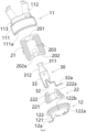
- Figure 1 shows an illustrative perspective view of connector 1 according to an exemplary embodiment of the present invention
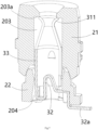
- Figure 2 shows an illustrative axial sectional view of connector 1 according to an exemplary embodiment of the present invention
- Figure 3 shows an illustrative exploded view of connector 1 according to an exemplary embodiment of the present invention
- Figure 4 shows an illustrative exploded sectional view of connector 1 according to an exemplary embodiment of the present invention
- Figure 5 shows an illustrative axial sectional view of the insulator 20 of connector 1 according to an exemplary embodiment of the present invention
- Figure 6 shows an illustrative exploded sectional view of the insulator 20 of a connector according to an exemplary embodiment of the present invention.
- a connector 1 is disclosed.
- the connector 1 mainly includes an outer conductor 10, an insulator 20, and a central terminal 30.
- the outer conductor 10 includes an upper outer conductor 11 and a lower outer conductor 12.
- the insulator 20 is arranged in the outer conductor 10 and includes an upper insulator 21 and a lower insulator 22.
- the central terminal 30 is set in the insulator 20.
- Figure 12 shows an illustrative axial sectional view of a connector assembly according to an exemplary embodiment of the present invention, where there is no radial deviation between connector 1 and mating connector 1';
- Figure 13 shows an illustrative axial sectional view of a connector assembly according to an exemplary embodiment of the present invention, where there is a significant radial deviation between connector 1 and mating connector 1'.
- the upper insulator 21 and the lower insulator 22 are assembled together in a sliding fit, allowing the upper insulator 21 to move relative to the lower insulator 22.
- the upper insulator 21 and the lower insulator 22 are assembled together in a spherical fit, allowing the upper insulator 21 to rotate around a sphere center relative to the lower insulator 22.
- the present invention is not limited to the illustrated embodiments.
- the upper insulator 21 and the lower insulator 22 can also be assembled together in an arc-shaped fit, allowing the upper insulator 21 to slide relative to the lower insulator 22.
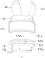
- Figure 10 shows an illustrative exploded sectional view of the outer conductor 10 of connector 1 according to an exemplary embodiment of the present invention
- Figure 11 shows an illustrative section view of the assembly of the outer conductor 10 of connector 1 according to an exemplary embodiment of the present invention.
- the upper outer conductor 11 and the lower outer conductor 12 are movably engaged together, allowing the upper outer conductor 11 to rotate around the same sphere center together with the upper insulator 21.
- the upper insulator 21 has a lower port 202
- the lower insulator 22 has an upper end 222
- the upper end 222 of the lower insulator 22 is inserted into the lower port 202 of the upper insulator 21.
- the lower port 202 of the upper insulator 21 has a spherical inner surface 202a
- the upper end 222 of the lower insulator 22 has a spherical outer surface 222a
- the spherical inner surface 202a is fitted with the spherical outer surface 222a.
- the upper insulator 21 can rotate relative to the lower insulator 22 around the center of the spherical inner surface 202a and the spherical outer surface 222a.
- the upper outer conductor 11 comprises a cylinder body portion 111 and multiple elastic arms 112.
- the cylinder body portion 111 has an upper end and a lower end that are axially opposite to each other.
- Multiple elastic arms 112 are connected to the upper end of the cylinder body portion 111 and evenly spaced around the cylinder body portion 111.
- the lower end of the cylinder body portion 111 is movably engaged to the lower outer conductor 12, and the elastic arm 112 is used for electrical contact with a mating outer conductor 10' of a mating connector 1'.
- the upper outer conductor 11 and the upper insulator 21 are kept together to ensure that they can rotate around the same sphere center together.
- the cylinder body portion 111 has a neck 113 located at its upper end, and the roots of multiple elastic arms 112 are connected to the upper periphery of the neck 113.
- a first snap slot 11a is formed on the neck 113, and a first protrusion 21a is formed on the upper insulator 21, which is engaged in the first snap slot 11a.
- a second protrusion 21b is also formed on the upper insulator 21, the second protrusion 21b is clamped between the roots of adj acent elastic arms 112 and pressed against the upper periphery of the neck 113.
- the lower outer conductor 12 comprises a cylindrical portion 121, a flange portion 122, and a welding portion 12a.
- the cylindrical portion 121 has upper and lower ends opposite to each other in its axial direction.
- the flange portion 122 is connected to the upper end of the cylindrical portion 121.
- the welding portion 12a is connected to the lower end of the cylindrical portion 121 for welding to a circuit board (not shown).
- the flange portion 122 is annular and protrudes outward relative to the outer circumference of the cylindrical portion 121.
- the flange portion 122 is inserted into the lower end of the cylinder body portion 111.
- the outer surface of the flange portion 122 is in interference fit with the inner wall surface of the lower end of the cylinder body portion 111 to ensure that the cylinder body portion 111 can always maintain electrical contact with the flange portion 122 when the upper outer conductor 11 is rotated.
- a flipped edge portion 111a is formed at the lower end of the cylinder body portion 111.
- the flipped edge portion 111a is curled inward and suitable for pressing against the bottom 122a of the flange portion 122 to prevent the cylinder body portion 111 from being detached from the flange portion 122 when the upper outer conductor 11 is rotated.
- multiple longitudinally extending dividing slits 122b are formed on the flange portion 122, and the multiple dividing slits 122b are spaced around the flange portion 122, so that the flange portion 122 is divided into multiple cantilevers.
- a conical guide slope 122c is formed on the flange portion 122, which is used to guide the flange portion 122 into the lower end of the cylinder body portion 111.
- Figure 7 shows an illustrative axial sectional view of the insulator 20 and central terminal 30 of a connector according to an exemplary embodiment of the present invention
- Figure 8 shows an illustrative perspective view of the central terminal 30 of a connector according to an exemplary embodiment of the present invention
- Figure 9 shows an illustrative axial sectional view of the central terminal 30 of a connector according to an exemplary embodiment of the present invention.
- the lower insulator 22 has a cylindrical base 221, and the outer peripheral surface of the cylindrical base 221 is in interference fit with the inner peripheral surface of the cylindrical portion 121 of the lower outer conductor 12 to keep the lower outer conductor 12 and the lower insulator 22 together.
- a positioning slot 121a is formed on the lower periphery of the cylindrical portion 121 of the lower outer conductor 12, and a positioning protrusion 221a is formed on the cylindrical base 221 of the lower insulator 22.
- the positioning protrusion 221a is matched with the positioning slot 121a.
- the central terminal 30 comprises a main body 33, an elastic contact portion 31, and an elastic connection part 32.
- the main body 33 is cylindrical and has upper and lower ends opposite to each other in its axial direction.
- the elastic contact portion 31 is connected to the upper end of the main body 33 for electrical contact with the mating terminal 30' of the mating connector 1'.
- One end of the elastic connection part 32 is connected to the lower periphery of the main body 33, and the other end 32a is used for soldering to the circuit board.
- the upper part of the main body 33 is retained in the upper insulator 21, allowing the central terminal 30 to rotate around the sphere center together with the upper insulator 21.
- an upper accommodating hole 203 is formed in the upper insulator 21.
- the elastic contact part 31 and the upper part of the main body 33 of the center terminal 30 are accommodated in the upper accommodating hole 203.
- the outer diameter of the main body 33 is equal to or slightly smaller than the inner diameter of the upper accommodating hole 203, so that there is no gap or a gap smaller than a predetermined value between the outer peripheral surface of the main body 33 and the inner peripheral surface of the upper accommodating hole 203. In this way, the volume of the upper insulator 21 and the entire connector 1 can be reduced, especially the radial size of the entire connector 1 can be reduced.
- a lower accommodating hole 204 is formed in the lower insulator 22.
- the elastic connection part 32 and the lower part of the main body 33 of the center terminal 30 are accommodated in the lower accommodating hole 204.
- the inner diameter of the lower accommodating hole 204 is greater than the outer diameter of the main body 33 to allow the lower part of the main body 33 to swing radially in the lower accommodating hole 204, thereby allowing the central terminal 30 to rotate together with the upper insulator 21.
- the elastic connection part 32 has at least one bending segment located between its two ends, allowing the elastic connection part 32 to deform from an initial state (as shown in Figure 12 ) to another state different from the initial state (such as the state shown in Figure 13 ) when the center terminal 30 is rotated together with the upper insulator 21.
- a protrusion 33c is formed on the main body 33 of the central terminal 30, and a slot 21c is formed on the upper insulator 21.
- the protrusion 33c is engaged with the slot 21c to maintain the main body 33 in the upper insulator 21.
- the elastic contact portion 31 of the center terminal 30 comprises a trumpet shaped end portion 311 and a conical connection portion 312.
- the conical connection portion 312 is connected between the trumpet shaped end portion 311 and the main body 33.
- the trumpet shaped end portion 311 is used to guide the insertion of the mating terminal 30' and to make electrical contact with the inserted mating terminal 30'.
- the diameter of the conical connection portion 312 gradually increases from the trumpet shaped end portion 311 towards the main body 33.
- multiple axial dividing slits 31a are formed on the elastic contact portion 31 of the center terminal 30.
- the multiple axial dividing slits 31a are spaced in the circumferential direction of the elastic contact portion 31, causing the elastic contact portion 31 to be divided into multiple elastic cantilevers.
- a trumpet shaped guide inlet 201 is formed on the upper end face of the upper insulator 21 and splayed outward.
- the minimum inner diameter of the trumpet shaped guide inlet 201 is equal to the maximum inner diameter of the trumpet shaped end portion 311.
- the inner diameter of the trumpet shaped guide inlet 201 gradually increases from the trumpet shaped end portion 311 upwards to guide the mating terminal 30' into the elastic contact part 31 of the center terminal 30.
- a positioning step 203a is formed in the upper insulator 21, and the trumpet shaped end portion 311 is axially pressed against the positioning step 203a to position the center terminal 30 axially.
- a connector assembly is also disclosed.
- the connector assembly mainly includes a connector 1 and a mating connector 1'.
- the mating connector 1' is mated with the connector 1.
- the mating connector 1' includes: a mating outer conductor 10' and a mating terminal 30'.
- the mating outer conductor 10' is mated with the upper outer conductor 11 of the connector 1.
- the mating terminal 30' is provided in the mating outer conductor 10' and is used for mating with the center terminal 30 of the connector 1.
- the upper outer conductor 11 is inserted into the mating outer conductor 10', and the elastic arm 112 of the upper outer conductor 11 is in electrical contact with the inner wall surface of the mating outer conductor 10'.
- the mating terminal 30' is into the elastic contact part 31 of the center terminal 30, and the elastic contact part 31 of the center terminal 30 is in electrical contact with the mating terminal 30'.
Landscapes
- Coupling Device And Connection With Printed Circuit (AREA)
Abstract
The present invention discloses a connector and a connector assembly. The connector comprises: an outer conductor (10) including an upper outer conductor (11) and a lower outer conductor (12); an insulator (20) which is provided in the outer conductor (10) and includes an upper insulator (21) and a lower insulator (22); and a central terminal (30) which is provided in the insulator (20). The upper insulator (21) and the lower insulator (22) are assembled together in a sliding fit, allowing the upper insulator (21) to move relative to the lower insulator (22), the upper outer conductor (11) and the lower outer conductor (12) are movably engaged together, allowing the upper outer conductor (11) to move together with the upper insulator (21). Therefore, the present invention can reduce the bias pressure on the elastic arm of the upper outer conductor, thereby effectively preventing plastic deformation of the elastic arm of the outer conductor. In addition, the present invention can also reduce the volume of the insulator, which is conducive to achieving miniaturization of the connector.
Description
- This application claims the benefit of Chinese Patent Application No.
CN202310763581.3 filed on June 27, 2023 - The present invention relates to a connector and a connector assembly comprising the connector.
- In the prior art, a coaxial connector typically includes an outer conductor, an insulator placed in the outer conductor, and a central terminal placed in the insulator. Multiple elastic cantilevers are formed on the outer conductor, which are used for electrical contact with the inner wall of the outer conductor of the mating connector. The central terminal has an elastic contact part, which is used for electrical contact with the mating terminal of the mating connector.
- In the prior art, when there is a significant radial deviation between the coaxial connector and the mating connector, the central terminal and the elastic cantilever of the outer conductor of the connector will be offset to one side under the pushing of the mating connector to absorb the radial deviation between the coaxial connector and the mating connector, ensuring reliable electrical contact between the two.
- However, in the prior art, when there is a significant radial deviation between the coaxial connector and the mating connector, the elastic cantilever of the outer conductor of the connector will be subjected to significant bias pressure, which will cause plastic deformation of the elastic cantilever of the outer conductor. In addition, in order to ensure that the central terminal can be offset in the insulator, it is necessary to form a larger inner cavity in the insulator, which will increase the volume of the insulator, leading to an increase in the volume of the entire connector, which is not conducive to the miniaturization of the connector.
- The present invention has been made to overcome or alleviate at least one aspect of the above mentioned disadvantages.
- According to an aspect of the present invention, there is provided a connector. The connector comprises: an outer conductor including an upper outer conductor and a lower outer conductor; an insulator which is provided in the outer conductor and includes an upper insulator and a lower insulator; and a central terminal which is provided in the insulator. The upper insulator and the lower insulator are assembled together in a sliding fit, allowing the upper insulator to move relative to the lower insulator. The upper outer conductor and the lower outer conductor are movably engaged together, allowing the upper outer conductor to move together with the upper insulator.
- According to an exemplary embodiment of the present invention, the upper insulator and the lower insulator are assembled together in a spherical fit, so that the upper insulator can rotate around a sphere center relative to the lower insulator; the upper outer conductor can rotate around the same sphere center together with the upper insulator.
- According to another exemplary embodiment of the present invention, the upper insulator has a lower port, the lower insulator has an upper end, and the upper end of the lower insulator is inserted into the lower port of the upper insulator; the lower port of the upper insulator has a spherical inner surface, the upper end of the lower insulator has a spherical outer surface, and the spherical inner surface is fitted with the spherical outer surface.
- According to another exemplary embodiment of the present invention, the upper outer conductor comprises: a cylinder body portion which has an upper end and a lower end axially opposite to each other; and multiple elastic arms which are connected to the upper end of the cylinder body portion and evenly spaced around the cylinder body portion. The lower end of the cylinder body portion is movably engaged with the lower outer conductor, and the elastic arms are used for electrical contact with a mating outer conductor of a mating connector.
- According to another exemplary embodiment of the present invention, the upper outer conductor and the upper insulator are kept together to ensure that they can rotate around the same sphere center together.
- According to another exemplary embodiment of the present invention, the cylinder body portion has a neck located at its upper end, and the roots of the multiple elastic arms are connected to the upper periphery of the neck; a first snap slot is formed on the neck, and a first protrusion is formed on the upper insulator, the first protrusion is engaged in the first snap slot.
- According to another exemplary embodiment of the present invention, a second protrusion is formed on the upper insulator, which is clamped between the roots of adjacent elastic arms and pressed against the upper periphery of the neck.
- According to another exemplary embodiment of the present invention, the lower outer conductor comprises: a cylindrical portion which has an upper end and a lower end axially opposite to each other; a flange portion connected to the upper end of the cylindrical portion; and a welding portion which is connected to the lower end of the cylindrical portion and is used for welding to a circuit board. The flange portion is annular and protrudes outward relative to the outer circumference of the cylindrical portion, the flange portion is inserted into the lower end of the cylinder body portion; the outer peripheral surface of the flange portion is in interference fit with the inner wall surface of the lower end of the cylinder body portion to ensure that the cylinder body portion is always in electrical contact with the flange portion when the upper outer conductor is rotated.
- According to another exemplary embodiment of the present invention, a flipped edge portion is formed at the lower end of the cylinder body portion, the flipped edge portion is inward curled and suitable to rest against the bottom of the flange portion to prevent the cylinder body portion from being detached from the flange portion when the upper outer conductor is rotated.
- According to another exemplary embodiment of the present invention, multiple dividing slits axially extending are formed on the flange portion, and the multiple dividing slits are arranged at intervals in the circumferential direction of the flange portion, so that the flange portion is divided into multiple cantilevers; a conical guide slope is formed on the flange portion for guiding the flange portion into the lower end of the cylinder body portion.
- According to another exemplary embodiment of the present invention, the lower insulator has a cylindrical base, and the outer peripheral surface of the cylindrical base is in interference fit with the inner peripheral surface of the cylindrical portion of the lower outer conductor to keep the lower outer conductor and the lower insulator together.
- According to another exemplary embodiment of the present invention, a positioning slot is formed on the lower periphery of the cylindrical portion of the lower outer conductor, and a positioning protrusion is formed on the cylindrical base of the lower insulator, the positioning protrusion is matched with the positioning slot.
- According to another exemplary embodiment of the present invention, the central terminal comprises: a main body which is cylindrical and has an upper end and a lower end axially opposite to each other; an elastic contact part which is connected to the upper end of the main body for electrical contact with the mating terminal of the mating connector; and an elastic connection part, one end of which is connected to the lower periphery of the main body, and the other end is used for soldering to a circuit board, the upper part of the main body is kept in the upper insulator, so that the central terminal can rotate around the sphere center together with the upper insulator.
- According to another exemplary embodiment of the present invention, an upper accommodating hole is formed in the upper insulator, and the elastic contact part and the upper part of the main body of the central terminal are accommodated in the upper accommodating hole; the outer diameter of the main body is equal to or slightly smaller than the inner diameter of the upper accommodating hole, so that there is no gap or a gap smaller than a predetermined value between the outer peripheral surface of the main body and the inner peripheral surface of the upper accommodating hole.
- According to another exemplary embodiment of the present invention, a lower accommodating hole is formed in the lower insulator, and the elastic connection part and the lower part of the main body of the central terminal are accommodated in the lower accommodating hole; the inner diameter of the lower accommodating hole is greater than the outer diameter of the main body to allow the lower part of the main body to swing radially in the lower accommodating hole, thereby allowing the central terminal to rotate together with the upper insulator.
- According to another exemplary embodiment of the present invention, the elastic connection part has at least one bending segment located between its two ends, enabling the elastic connection part to deform from an initial state to another state different from the initial state when the central terminal is rotated together with the upper insulator.
- According to another exemplary embodiment of the present invention, a protrusion is formed on the main body of the central terminal, and a slot is formed on the upper insulator, the protrusion is engaged with the slot to keep the main body in the upper insulator.
- According to another exemplary embodiment of the present invention, the elastic contact part of the central terminal comprises: a trumpet shaped end portion; and a conical connection portion which is connected between the trumpet shaped end portion and the main body. The trumpet shaped end portion is used to guide the insertion of the mating terminal and electrical contact with the inserted mating terminal; the diameter of the conical connection portion gradually increases from the trumpet shaped end portion towards the main body.
- According to another exemplary embodiment of the present invention, multiple axial dividing slits are formed on the elastic contact part of the central terminal, and the multiple axial dividing slits are arranged at intervals in the circumferential direction of the elastic contact part, so that the elastic contact part is divided into multiple elastic cantilevers.
- According to another exemplary embodiment of the present invention, a trumpet shaped guide inlet is formed on the upper end face of the upper insulator and is splayed outward, the minimum inner diameter of the trumpet shaped guide inlet is equal to the maximum inner diameter of the trumpet shaped end portion; the inner diameter of the trumpet shaped guide inlet gradually increases upwards from the trumpet shaped end portion to guide the mating terminal into the elastic contact part of the center terminal.
- According to another exemplary embodiment of the present invention, a positioning step is formed in the upper insulator, and the trumpet shaped end portion is axially against the positioning step to axially position the center terminal.
- According to another aspect of the present invention, there is provided a connector assembly. The connector assembly comprises: the above connector; and a mating connector mated with the connector. The mating connector comprises: a mating outer conductor mated with the upper outer conductor of the connector; and a mating terminal provided in the mating outer conductor for mating with the center terminal of the connector.
- According to an exemplary embodiment of the present invention, the upper outer conductor is inserted into the mating outer conductor, and the elastic arm of the upper outer conductor is in electrical contact with the inner wall surface of the mating outer conductor; the mating terminal is inserted into the elastic contact portion of the center terminal, and the elastic contact portion of the center terminal is in electrical contact with the mating terminal.
- In the aforementioned exemplary embodiments of the present invention, the upper outer conductor can be moved together with the upper insulator, thereby reducing the bias pressure on the elastic arm of the upper outer conductor and effectively preventing plastic deformation of the elastic arm of the outer conductor.
- In some exemplary embodiments of the present invention, the upper outer conductor can be rotated around the sphere center together with the upper insulator, thereby reducing the bias pressure on the elastic arm of the upper outer conductor and effectively preventing plastic deformation of the elastic arm of the outer conductor.
- In addition, in some exemplary embodiments according to the present invention, the central terminal can be rotated around the sphere center together with the upper insulator. Therefore, the gap between the central terminal and the upper insulator can be zero or very small, which can reduce the volume of the insulator and facilitate the miniaturization of the connector.
- The above and other features of the present invention will become more apparent by describing in detail exemplary embodiments thereof with reference to the accompanying drawings, in which:
-
Figure 1 shows an illustrative perspective view of a connector according to an exemplary embodiment of the present invention; -
Figure 2 shows an illustrative axial sectional view of a connector according to an exemplary embodiment of the present invention; -
Figure 3 shows an illustrative exploded view of a connector according to an exemplary embodiment of the present invention; -
Figure 4 shows an illustrative exploded sectional view of a connector according to an exemplary embodiment of the present invention; -
Figure 5 shows an illustrative axial sectional view of the insulator of a connector according to an exemplary embodiment of the present invention; -
Figure 6 shows an illustrative exploded sectional view of the insulator of a connector according to an exemplary embodiment of the present invention; -
Figure 7 shows an illustrative axial sectional view of the insulator and central terminal of a connector according to an exemplary embodiment of the present invention; -
Figure 8 shows an illustrative perspective view of the central terminal of a connector according to an exemplary embodiment of the present invention; -
Figure 9 shows an illustrative axial sectional view of the central terminal of a connector according to an exemplary embodiment of the present invention; -
Figure 10 shows an illustrative exploded sectional view of the outer conductor of a connector according to an exemplary embodiment of the present invention; -
Figure 11 shows an illustrative section view of the assembly of the outer conductor of a connector according to an exemplary embodiment of the present invention; -
Figure 12 shows an illustrative axial sectional view of a connector assembly according to an exemplary embodiment of the present invention, where there is no radial deviation between the connector and the mating connector; and -
Figure 13 shows an illustrative axial sectional view of a connector assembly according to an exemplary embodiment of the present invention, where there is a significant radial deviation between the connector and the mating connector. - Exemplary embodiments of the present disclosure will be described hereinafter in detail with reference to the attached drawings, wherein the like reference numerals refer to the like elements. The present disclosure may, however, be embodied in many different forms and should not be construed as being limited to the embodiment set forth herein; rather, these embodiments are provided so that the present disclosure will be thorough and complete, and will fully convey the concept of the disclosure to those skilled in the art.
- In the following detailed description, for purposes of explanation, numerous specific details are set forth in order to provide a thorough understanding of the disclosed embodiments. It will be apparent, however, that one or more embodiments may be practiced without these specific details. In other instances, well-known structures and devices are schematically shown in order to simplify the drawing.
- According to a general concept of the present invention, there is provided a connector. The connector comprises: an outer conductor including an upper outer conductor and a lower outer conductor; an insulator which is provided in the outer conductor and includes an upper insulator and a lower insulator; and a central terminal which is provided in the insulator. The upper insulator and the lower insulator are assembled together in a sliding fit, allowing the upper insulator to move relative to the lower insulator. The upper outer conductor and the lower outer conductor are movably engaged together, allowing the upper outer conductor to move together with the upper insulator.
- According to another general concept of the present invention, there is provided a connector assembly. The connector assembly comprises: the above connector; and a mating connector mated with the connector. The mating connector comprises: a mating outer conductor mated with the upper outer conductor of the connector; and a mating terminal provided in the mating outer conductor for mating with the center terminal of the connector.
-
Figure 1 shows an illustrative perspective view ofconnector 1 according to an exemplary embodiment of the present invention;Figure 2 shows an illustrative axial sectional view ofconnector 1 according to an exemplary embodiment of the present invention;Figure 3 shows an illustrative exploded view ofconnector 1 according to an exemplary embodiment of the present invention;Figure 4 shows an illustrative exploded sectional view ofconnector 1 according to an exemplary embodiment of the present invention;Figure 5 shows an illustrative axial sectional view of theinsulator 20 ofconnector 1 according to an exemplary embodiment of the present invention;Figure 6 shows an illustrative exploded sectional view of theinsulator 20 of a connector according to an exemplary embodiment of the present invention. - As shown in
Figures 1 to 6 , in an exemplary embodiment of the present invention, aconnector 1 is disclosed. Theconnector 1 mainly includes anouter conductor 10, aninsulator 20, and acentral terminal 30. Theouter conductor 10 includes an upperouter conductor 11 and a lowerouter conductor 12. Theinsulator 20 is arranged in theouter conductor 10 and includes anupper insulator 21 and alower insulator 22. Thecentral terminal 30 is set in theinsulator 20. -
Figure 12 shows an illustrative axial sectional view of a connector assembly according to an exemplary embodiment of the present invention, where there is no radial deviation betweenconnector 1 and mating connector 1';Figure 13 shows an illustrative axial sectional view of a connector assembly according to an exemplary embodiment of the present invention, where there is a significant radial deviation betweenconnector 1 and mating connector 1'. - As shown in
Figures 1-6 and12-13 , in the illustrated embodiments, theupper insulator 21 and thelower insulator 22 are assembled together in a sliding fit, allowing theupper insulator 21 to move relative to thelower insulator 22. In the illustrated embodiment, theupper insulator 21 and thelower insulator 22 are assembled together in a spherical fit, allowing theupper insulator 21 to rotate around a sphere center relative to thelower insulator 22. However, the present invention is not limited to the illustrated embodiments. For example, theupper insulator 21 and thelower insulator 22 can also be assembled together in an arc-shaped fit, allowing theupper insulator 21 to slide relative to thelower insulator 22. -
Figure 10 shows an illustrative exploded sectional view of theouter conductor 10 ofconnector 1 according to an exemplary embodiment of the present invention;Figure 11 shows an illustrative section view of the assembly of theouter conductor 10 ofconnector 1 according to an exemplary embodiment of the present invention. - As shown in
Figures 1-6 and10-13 , in the illustrated embodiments, the upperouter conductor 11 and the lowerouter conductor 12 are movably engaged together, allowing the upperouter conductor 11 to rotate around the same sphere center together with theupper insulator 21. - As shown in
Figures 1-6 and10-13 , in the illustrated embodiments, theupper insulator 21 has alower port 202, thelower insulator 22 has anupper end 222, and theupper end 222 of thelower insulator 22 is inserted into thelower port 202 of theupper insulator 21. Thelower port 202 of theupper insulator 21 has a sphericalinner surface 202a, theupper end 222 of thelower insulator 22 has a sphericalouter surface 222a, and the sphericalinner surface 202a is fitted with the sphericalouter surface 222a. In this way, theupper insulator 21 can rotate relative to thelower insulator 22 around the center of the sphericalinner surface 202a and the sphericalouter surface 222a. - As shown in
Figures 1-6 and10-13 , in the illustrated embodiment, the upperouter conductor 11 comprises acylinder body portion 111 and multipleelastic arms 112. Thecylinder body portion 111 has an upper end and a lower end that are axially opposite to each other. Multipleelastic arms 112 are connected to the upper end of thecylinder body portion 111 and evenly spaced around thecylinder body portion 111. The lower end of thecylinder body portion 111 is movably engaged to the lowerouter conductor 12, and theelastic arm 112 is used for electrical contact with a mating outer conductor 10' of a mating connector 1'. - As shown in
Figures 1-6 and10-13 , in the illustrated embodiment, the upperouter conductor 11 and theupper insulator 21 are kept together to ensure that they can rotate around the same sphere center together. - As shown in
Figures 1-6 and10-13 , in the illustrated embodiments, thecylinder body portion 111 has aneck 113 located at its upper end, and the roots of multipleelastic arms 112 are connected to the upper periphery of theneck 113. Afirst snap slot 11a is formed on theneck 113, and afirst protrusion 21a is formed on theupper insulator 21, which is engaged in thefirst snap slot 11a. - As shown in
Figures 1-6 and10-13 , in the illustrated embodiments, asecond protrusion 21b is also formed on theupper insulator 21, thesecond protrusion 21b is clamped between the roots of adj acentelastic arms 112 and pressed against the upper periphery of theneck 113. - As shown in
Figures 1-6 and10-13 , in the illustrated embodiment, the lowerouter conductor 12 comprises acylindrical portion 121, aflange portion 122, and awelding portion 12a. Thecylindrical portion 121 has upper and lower ends opposite to each other in its axial direction. Theflange portion 122 is connected to the upper end of thecylindrical portion 121. Thewelding portion 12a is connected to the lower end of thecylindrical portion 121 for welding to a circuit board (not shown). - As shown in
Figures 1-6 and10-13 , in the illustrated embodiments, theflange portion 122 is annular and protrudes outward relative to the outer circumference of thecylindrical portion 121. Theflange portion 122 is inserted into the lower end of thecylinder body portion 111. The outer surface of theflange portion 122 is in interference fit with the inner wall surface of the lower end of thecylinder body portion 111 to ensure that thecylinder body portion 111 can always maintain electrical contact with theflange portion 122 when the upperouter conductor 11 is rotated. - As shown in
Figures 1-6 and10-13 , in the illustrated embodiments, a flippededge portion 111a is formed at the lower end of thecylinder body portion 111. The flippededge portion 111a is curled inward and suitable for pressing against the bottom 122a of theflange portion 122 to prevent thecylinder body portion 111 from being detached from theflange portion 122 when the upperouter conductor 11 is rotated. - As shown in
Figures 1-6 and10-13 , in the illustrated embodiments, multiple longitudinally extending dividingslits 122b are formed on theflange portion 122, and the multiple dividingslits 122b are spaced around theflange portion 122, so that theflange portion 122 is divided into multiple cantilevers. Aconical guide slope 122c is formed on theflange portion 122, which is used to guide theflange portion 122 into the lower end of thecylinder body portion 111. -
Figure 7 shows an illustrative axial sectional view of theinsulator 20 andcentral terminal 30 of a connector according to an exemplary embodiment of the present invention;Figure 8 shows an illustrative perspective view of thecentral terminal 30 of a connector according to an exemplary embodiment of the present invention;Figure 9 shows an illustrative axial sectional view of thecentral terminal 30 of a connector according to an exemplary embodiment of the present invention. - As shown in
Figures 1 to 13 , in the illustrated embodiments, thelower insulator 22 has acylindrical base 221, and the outer peripheral surface of thecylindrical base 221 is in interference fit with the inner peripheral surface of thecylindrical portion 121 of the lowerouter conductor 12 to keep the lowerouter conductor 12 and thelower insulator 22 together. - As shown in
Figures 1 to 13 , in the illustrated embodiments, apositioning slot 121a is formed on the lower periphery of thecylindrical portion 121 of the lowerouter conductor 12, and apositioning protrusion 221a is formed on thecylindrical base 221 of thelower insulator 22. Thepositioning protrusion 221a is matched with thepositioning slot 121a. - As shown in
Figures 1 to 13 , in the illustrated embodiments, thecentral terminal 30 comprises amain body 33, anelastic contact portion 31, and anelastic connection part 32. Themain body 33 is cylindrical and has upper and lower ends opposite to each other in its axial direction. Theelastic contact portion 31 is connected to the upper end of themain body 33 for electrical contact with the mating terminal 30' of the mating connector 1'. One end of theelastic connection part 32 is connected to the lower periphery of themain body 33, and theother end 32a is used for soldering to the circuit board. The upper part of themain body 33 is retained in theupper insulator 21, allowing thecentral terminal 30 to rotate around the sphere center together with theupper insulator 21. - As shown in
Figures 1 to 13 , in the illustrated embodiments, an upperaccommodating hole 203 is formed in theupper insulator 21. Theelastic contact part 31 and the upper part of themain body 33 of thecenter terminal 30 are accommodated in the upperaccommodating hole 203. The outer diameter of themain body 33 is equal to or slightly smaller than the inner diameter of the upperaccommodating hole 203, so that there is no gap or a gap smaller than a predetermined value between the outer peripheral surface of themain body 33 and the inner peripheral surface of the upperaccommodating hole 203. In this way, the volume of theupper insulator 21 and theentire connector 1 can be reduced, especially the radial size of theentire connector 1 can be reduced. - As shown in
Figures 1 to 13 , in the illustrated embodiments, a loweraccommodating hole 204 is formed in thelower insulator 22. Theelastic connection part 32 and the lower part of themain body 33 of thecenter terminal 30 are accommodated in the loweraccommodating hole 204. The inner diameter of the loweraccommodating hole 204 is greater than the outer diameter of themain body 33 to allow the lower part of themain body 33 to swing radially in the loweraccommodating hole 204, thereby allowing thecentral terminal 30 to rotate together with theupper insulator 21. - As shown in
Figures 1 to 13 , in the illustrated embodiments, theelastic connection part 32 has at least one bending segment located between its two ends, allowing theelastic connection part 32 to deform from an initial state (as shown inFigure 12 ) to another state different from the initial state (such as the state shown inFigure 13 ) when thecenter terminal 30 is rotated together with theupper insulator 21. - As shown in
Figures 1 to 13 , in the illustrated embodiments, aprotrusion 33c is formed on themain body 33 of thecentral terminal 30, and aslot 21c is formed on theupper insulator 21. Theprotrusion 33c is engaged with theslot 21c to maintain themain body 33 in theupper insulator 21. - As shown in
Figures 1 to 13 , in the illustrated embodiments, theelastic contact portion 31 of thecenter terminal 30 comprises a trumpet shapedend portion 311 and aconical connection portion 312. Theconical connection portion 312 is connected between the trumpet shapedend portion 311 and themain body 33. The trumpet shapedend portion 311 is used to guide the insertion of the mating terminal 30' and to make electrical contact with the inserted mating terminal 30'. The diameter of theconical connection portion 312 gradually increases from the trumpet shapedend portion 311 towards themain body 33. - As shown in
Figures 1 to 13 , in the illustrated embodiments, multiple axial dividing slits 31a are formed on theelastic contact portion 31 of thecenter terminal 30. The multiple axial dividing slits 31a are spaced in the circumferential direction of theelastic contact portion 31, causing theelastic contact portion 31 to be divided into multiple elastic cantilevers. - As shown in
Figures 1 to 13 , in the illustrated embodiments, a trumpet shapedguide inlet 201 is formed on the upper end face of theupper insulator 21 and splayed outward. The minimum inner diameter of the trumpet shapedguide inlet 201 is equal to the maximum inner diameter of the trumpet shapedend portion 311. The inner diameter of the trumpet shapedguide inlet 201 gradually increases from the trumpet shapedend portion 311 upwards to guide the mating terminal 30' into theelastic contact part 31 of thecenter terminal 30. - As shown in
Figures 1 to 13 , in the illustrated embodiments, apositioning step 203a is formed in theupper insulator 21, and the trumpet shapedend portion 311 is axially pressed against thepositioning step 203a to position thecenter terminal 30 axially. - As shown in
Figures 1 to 13 , in another exemplary embodiment of the present invention, a connector assembly is also disclosed. The connector assembly mainly includes aconnector 1 and a mating connector 1'. The mating connector 1' is mated with theconnector 1. The mating connector 1' includes: a mating outer conductor 10' and a mating terminal 30'. The mating outer conductor 10' is mated with the upperouter conductor 11 of theconnector 1. The mating terminal 30' is provided in the mating outer conductor 10' and is used for mating with thecenter terminal 30 of theconnector 1. - As shown in
Figures 1 to 13 , in the illustrated embodiments, the upperouter conductor 11 is inserted into the mating outer conductor 10', and theelastic arm 112 of the upperouter conductor 11 is in electrical contact with the inner wall surface of the mating outer conductor 10'. The mating terminal 30' is into theelastic contact part 31 of thecenter terminal 30, and theelastic contact part 31 of thecenter terminal 30 is in electrical contact with the mating terminal 30'. - As shown in
Figure 12 , in the illustrated embodiment, there is no radial deviation between theconnector 1 and the mating connector 1', that is, the central axis of theconnector 1 coincides with the central axis of the mating connector 1'. At this time, during the mating process between the mating connector 1' and theconnector 1, the upperouter conductor 11,upper insulator 21, andcentral terminal 30 ofconnector 1 will not rotate around the sphere center. - As shown in
Figure 13 , in the illustrated embodiment, there is a significant radial deviation between theconnector 1 and the mating connector 1'. At this time, during the mating process between the mating connector 1' and theconnector 1, the upperouter conductor 11,upper insulator 21, andcentral terminal 30 ofconnector 1 will rotate around the sphere center to absorb the radial deviation between theconnector 1 and the mating connector 1'. - It should be appreciated for those skilled in this art that the above embodiments are intended to be illustrated, and not restrictive. For example, many modifications may be made to the above embodiments by those skilled in this art, and various features described in different embodiments may be freely combined with each other without conflicting in configuration or principle.
- Although several exemplary embodiments have been shown and described, it would be appreciated by those skilled in the art that various changes or modifications may be made in these embodiments without departing from the principles and spirit of the disclosure, the scope of which is defined in the claims and their equivalents.
- As used herein, an element recited in the singular and proceeded with the word "a" or "an" should be understood as not excluding plural of said elements or steps, unless such exclusion is explicitly stated. Furthermore, references to "one embodiment" of the present invention are not intended to be interpreted as excluding the existence of additional embodiments that also incorporate the recited features. Moreover, unless explicitly stated to the contrary, embodiments "comprising" or "having" an element or a plurality of elements having a particular property may include additional such elements not having that property.
Claims (15)
- A connector, comprising:an outer conductor (10) including an upper outer conductor (11) and a lower outer conductor (12);an insulator (20) which is provided in the outer conductor (10) and includes an upper insulator (21) and a lower insulator (22); anda central terminal (30) which is provided in the insulator (20),wherein the upper insulator (21) and the lower insulator (22) are assembled together in a sliding fit, allowing the upper insulator (21) to move relative to the lower insulator (22),wherein the upper outer conductor (11) and the lower outer conductor (12) are movably engaged together, allowing the upper outer conductor (11) to move together with the upper insulator (21).
- The connector according to claim 1,wherein the upper insulator (21) and the lower insulator (22) are assembled together in a spherical fit, so that the upper insulator (21) can rotate around a sphere center relative to the lower insulator (22);wherein the upper outer conductor (11) can rotate around the same sphere center together with the upper insulator (21).
- The connector according to claim 2,wherein the upper insulator (21) has a lower port (202), the lower insulator (22) has an upper end (222), and the upper end (222) of the lower insulator (22) is inserted into the lower port (202) of the upper insulator (21);wherein the lower port (202) of the upper insulator (21) has a spherical inner surface (202a), the upper end (222) of the lower insulator (22) has a spherical outer surface (222a), and the spherical inner surface (202a) is fitted with the spherical outer surface (222a).
- The connector according to claim 2,wherein the upper outer conductor (11) comprises:a cylinder body portion (111) which has an upper end and a lower end axially opposite to each other; andmultiple elastic arms (112) which are connected to the upper end of the cylinder body portion (111) and evenly spaced around the cylinder body portion (111),wherein the lower end of the cylinder body portion (111) is movably engaged with the lower outer conductor (12), and the elastic arms (112) are used for electrical contact with a mating outer conductor (10') of a mating connector (1').
- The connector according to claim 4,wherein the upper outer conductor (11) and the upper insulator (21) are kept together to ensure that they can rotate around the same sphere center together;wherein the cylinder body portion (111) has a neck (113) located at its upper end, and the roots of the multiple elastic arms (112) are connected to the upper periphery of the neck (113);wherein a first snap slot (11a) is formed on the neck (113), and a first protrusion (21a) is formed on the upper insulator (21), the first protrusion (21a) is engaged in the first snap slot (111a);wherein a second protrusion (21b) is formed on the upper insulator (21), which is clamped between the roots of adjacent elastic arms (112) and pressed against the upper periphery of the neck (113).
- The connector according to claim 4,wherein the lower outer conductor (12) comprises:a cylindrical portion (121) which has an upper end and a lower end axially opposite to each other;a flange portion (122) connected to the upper end of the cylindrical portion (121); anda welding portion (12a) which is connected to the lower end of the cylindrical portion (121) and is used for welding to a circuit board,wherein the flange portion (122) is annular and protrudes outward relative to the outer circumference of the cylindrical portion (121), the flange portion (122) is inserted into the lower end of the cylinder body portion (111),wherein the outer peripheral surface of the flange portion (122) is in interference fit with the inner wall surface of the lower end of the cylinder body portion (111) to ensure that the cylinder body portion (111) is always in electrical contact with the flange portion (122) when the upper outer conductor (11) is rotated.
- The connector according to claim 6,
wherein a flipped edge portion (111a) is formed at the lower end of the cylinder body portion (111), the flipped edge portion (111a) is inward curled and suitable to rest against the bottom (122a) of the flange portion (122) to prevent the cylinder body portion (111) from being detached from the flange portion (122) when the upper outer conductor (11) is rotated. - The connector according to claim 6,wherein the lower insulator (22) has a cylindrical base (221), and the outer peripheral surface of the cylindrical base (221) is in interference fit with the inner peripheral surface of the cylindrical portion (121) of the lower outer conductor (12) to keep the lower outer conductor (12) and the lower insulator (22) together;wherein a positioning slot (121a) is formed on the lower periphery of the cylindrical portion (121) of the lower outer conductor (12), and a positioning protrusion (221a) is formed on the cylindrical base (221) of the lower insulator (22), the positioning protrusion (221a) is matched with the positioning slot (121a).
- The connector according to any one of claims 2-8,wherein the central terminal (30) comprises:a main body (33) which is cylindrical and has an upper end and a lower end axially opposite to each other;an elastic contact part (31) which is connected to the upper end of the main body (33) for electrical contact with the mating terminal (30') of the mating connector (1'); andan elastic connection part (32), one end of which is connected to the lower periphery of the main body (33), and the other end (32a) is used for soldering to a circuit board,wherein the upper part of the main body (33) is kept in the upper insulator (21), so that the central terminal (30) can rotate around the sphere center together with the upper insulator (21).
- The connector according to claim 9,wherein an upper accommodating hole (203) is formed in the upper insulator (21), and the elastic contact part (31) and the upper part of the main body (33) of the central terminal (30) are accommodated in the upper accommodating hole (203);wherein the outer diameter of the main body (33) is equal to or slightly smaller than the inner diameter of the upper accommodating hole (203), so that there is no gap or a gap smaller than a predetermined value between the outer peripheral surface of the main body (33) and the inner peripheral surface of the upper accommodating hole (203).
- The connector according to claim 9,wherein a lower accommodating hole (204) is formed in the lower insulator (22), and the elastic connection part (32) and the lower part of the main body (33) of the central terminal (30) are accommodated in the lower accommodating hole (204);wherein the inner diameter of the lower accommodating hole (204) is greater than the outer diameter of the main body (33) to allow the lower part of the main body (33) to swing radially in the lower accommodating hole (204), thereby allowing the central terminal (30) to rotate together with the upper insulator (21).
- The connector according to claim 9,
wherein the elastic connection part (32) has at least one bending segment located between its two ends, enabling the elastic connection part (32) to deform from an initial state to another state different from the initial state when the central terminal (30) is rotated together with the upper insulator (21). - The connector according to claim 9,
wherein a protrusion (33c) is formed on the main body (33) of the central terminal (30), and a slot (21c) is formed on the upper insulator (21), the protrusion (33c) is engaged with the slot (21c) to keep the main body (33) in the upper insulator (21). - The connector according to claim 9,wherein the elastic contact part (31) of the central terminal (30) comprises:a trumpet shaped end portion (311); anda conical connection portion (312) which is connected between the trumpet shaped end portion (311) and the main body (33),wherein the trumpet shaped end portion (311) is used to guide the insertion of the mating terminal (30') and electrical contact with the inserted mating terminal (30'),wherein the diameter of the conical connection portion (312) gradually increases from the trumpet shaped end portion (311) towards the main body (33).
- A connector assembly, comprising:the connector (1) as claimed in any one of claims 1-14; anda mating connector (1') mated with the connector (1),wherein the mating connector (1') comprises:a mating outer conductor (10') mated with the upper outer conductor (11) of the connector (1); anda mating terminal (30') provided in the mating outer conductor (10') for mating with the center terminal (30) of the connector (1).
Applications Claiming Priority (1)
| Application Number | Priority Date | Filing Date | Title |
|---|---|---|---|
| CN202310763581.3A CN119209064A (en) | 2023-06-27 | 2023-06-27 | Connector and connector assembly |
Publications (1)
| Publication Number | Publication Date |
|---|---|
| EP4485701A1 true EP4485701A1 (en) | 2025-01-01 |
Family
ID=91665144
Family Applications (1)
| Application Number | Title | Priority Date | Filing Date |
|---|---|---|---|
| EP24184254.1A Pending EP4485701A1 (en) | 2023-06-27 | 2024-06-25 | Connector and connector assembly |
Country Status (5)
| Country | Link |
|---|---|
| US (1) | US20250007210A1 (en) |
| EP (1) | EP4485701A1 (en) |
| JP (1) | JP2025005421A (en) |
| KR (1) | KR20250000898A (en) |
| CN (1) | CN119209064A (en) |
Citations (3)
| Publication number | Priority date | Publication date | Assignee | Title |
|---|---|---|---|---|
| US2404564A (en) * | 1944-01-27 | 1946-07-23 | William F Boehlke | Electric swivel connector |
| JP5816384B2 (en) * | 2012-02-27 | 2015-11-18 | テルコン カンパニー リミテッド | RF connector for board connection |
| CN111370953A (en) * | 2020-04-01 | 2020-07-03 | 上海航天科工电器研究院有限公司 | Board-to-board floating radio frequency connector of fuzz button floating structure |
-
2023
- 2023-06-27 CN CN202310763581.3A patent/CN119209064A/en active Pending
-
2024
- 2024-06-24 JP JP2024100935A patent/JP2025005421A/en active Pending
- 2024-06-25 EP EP24184254.1A patent/EP4485701A1/en active Pending
- 2024-06-26 KR KR1020240083782A patent/KR20250000898A/en active Pending
- 2024-06-27 US US18/756,796 patent/US20250007210A1/en active Pending
Patent Citations (3)
| Publication number | Priority date | Publication date | Assignee | Title |
|---|---|---|---|---|
| US2404564A (en) * | 1944-01-27 | 1946-07-23 | William F Boehlke | Electric swivel connector |
| JP5816384B2 (en) * | 2012-02-27 | 2015-11-18 | テルコン カンパニー リミテッド | RF connector for board connection |
| CN111370953A (en) * | 2020-04-01 | 2020-07-03 | 上海航天科工电器研究院有限公司 | Board-to-board floating radio frequency connector of fuzz button floating structure |
Also Published As
| Publication number | Publication date |
|---|---|
| JP2025005421A (en) | 2025-01-16 |
| US20250007210A1 (en) | 2025-01-02 |
| KR20250000898A (en) | 2025-01-03 |
| CN119209064A (en) | 2024-12-27 |
Similar Documents
| Publication | Publication Date | Title |
|---|---|---|
| US4743205A (en) | Female coaxial connector and method of making the same | |
| US11411347B2 (en) | Coaxial connector and board-to-board connector assembly | |
| US20170110844A1 (en) | Float adapter for electrical connector and method for making the same | |
| US20220376415A1 (en) | Coaxial connector and board-to-board connector assembly | |
| EP3671968A2 (en) | Electrical connector housing, electrical connector and electrical connector assembly | |
| US11664617B2 (en) | Electrical terminal, method for manufacturing elastic terminal, electrical connector and electronic device | |
| US4869686A (en) | Right angle electrical connector | |
| EP4283794A1 (en) | Elastic terminal ferrule, terminal assembly, and charging seat | |
| EP4485701A1 (en) | Connector and connector assembly | |
| EP3208894B1 (en) | Float adapter for electrical connector and method for making the same | |
| US6299491B1 (en) | RF connector clip ring | |
| CN210866559U (en) | Coaxial Connectors and Board-to-Board Connector Assemblies | |
| CN108511937A (en) | A kind of plate is to plate RF coaxial connector jack | |
| IL324132A (en) | Reliable and adaptable electrical connector with high current capacity | |
| CN210489873U (en) | Coaxial connector and board-to-board connector assembly | |
| CN107565250A (en) | Connector | |
| KR920010678B1 (en) | Manufacturing method of spring contact socket | |
| CN220189926U (en) | Connector and connector assembly | |
| CN206022693U (en) | Adapter | |
| CN217903523U (en) | Connector housing assembly, connector and connector assembly | |
| CN111916941A (en) | Connector | |
| CN223156307U (en) | Connector Terminals | |
| US12424805B2 (en) | Connector assembly | |
| US4138180A (en) | Plug | |
| JP2024084997A (en) | Female terminal fittings |
Legal Events
| Date | Code | Title | Description |
|---|---|---|---|
| PUAI | Public reference made under article 153(3) epc to a published international application that has entered the european phase |
Free format text: ORIGINAL CODE: 0009012 |
|
| STAA | Information on the status of an ep patent application or granted ep patent |
Free format text: STATUS: THE APPLICATION HAS BEEN PUBLISHED |
|
| AK | Designated contracting states |
Kind code of ref document: A1 Designated state(s): AL AT BE BG CH CY CZ DE DK EE ES FI FR GB GR HR HU IE IS IT LI LT LU LV MC ME MK MT NL NO PL PT RO RS SE SI SK SM TR |
|
| STAA | Information on the status of an ep patent application or granted ep patent |
Free format text: STATUS: REQUEST FOR EXAMINATION WAS MADE |
|
| 17P | Request for examination filed |
Effective date: 20250627 |