EP4485635A1 - Secondary battery - Google Patents
Secondary battery Download PDFInfo
- Publication number
- EP4485635A1 EP4485635A1 EP24177711.9A EP24177711A EP4485635A1 EP 4485635 A1 EP4485635 A1 EP 4485635A1 EP 24177711 A EP24177711 A EP 24177711A EP 4485635 A1 EP4485635 A1 EP 4485635A1
- Authority
- EP
- European Patent Office
- Prior art keywords
- current collector
- collector plate
- connection area
- plate
- secondary battery
- Prior art date
- Legal status (The legal status is an assumption and is not a legal conclusion. Google has not performed a legal analysis and makes no representation as to the accuracy of the status listed.)
- Pending
Links
Images


Classifications
-
- H—ELECTRICITY
- H01—ELECTRIC ELEMENTS
- H01M—PROCESSES OR MEANS, e.g. BATTERIES, FOR THE DIRECT CONVERSION OF CHEMICAL ENERGY INTO ELECTRICAL ENERGY
- H01M50/00—Constructional details or processes of manufacture of the non-active parts of electrochemical cells other than fuel cells, e.g. hybrid cells
- H01M50/50—Current conducting connections for cells or batteries
- H01M50/531—Electrode connections inside a battery casing
- H01M50/533—Electrode connections inside a battery casing characterised by the shape of the leads or tabs
-
- H—ELECTRICITY
- H01—ELECTRIC ELEMENTS
- H01M—PROCESSES OR MEANS, e.g. BATTERIES, FOR THE DIRECT CONVERSION OF CHEMICAL ENERGY INTO ELECTRICAL ENERGY
- H01M50/00—Constructional details or processes of manufacture of the non-active parts of electrochemical cells other than fuel cells, e.g. hybrid cells
- H01M50/10—Primary casings; Jackets or wrappings
- H01M50/102—Primary casings; Jackets or wrappings characterised by their shape or physical structure
- H01M50/107—Primary casings; Jackets or wrappings characterised by their shape or physical structure having curved cross-section, e.g. round or elliptic
-
- H—ELECTRICITY
- H01—ELECTRIC ELEMENTS
- H01M—PROCESSES OR MEANS, e.g. BATTERIES, FOR THE DIRECT CONVERSION OF CHEMICAL ENERGY INTO ELECTRICAL ENERGY
- H01M50/00—Constructional details or processes of manufacture of the non-active parts of electrochemical cells other than fuel cells, e.g. hybrid cells
- H01M50/10—Primary casings; Jackets or wrappings
- H01M50/172—Arrangements of electric connectors penetrating the casing
- H01M50/174—Arrangements of electric connectors penetrating the casing adapted for the shape of the cells
- H01M50/179—Arrangements of electric connectors penetrating the casing adapted for the shape of the cells for cells having curved cross-section, e.g. round or elliptic
-
- H—ELECTRICITY
- H01—ELECTRIC ELEMENTS
- H01M—PROCESSES OR MEANS, e.g. BATTERIES, FOR THE DIRECT CONVERSION OF CHEMICAL ENERGY INTO ELECTRICAL ENERGY
- H01M50/00—Constructional details or processes of manufacture of the non-active parts of electrochemical cells other than fuel cells, e.g. hybrid cells
- H01M50/30—Arrangements for facilitating escape of gases
- H01M50/342—Non-re-sealable arrangements
- H01M50/3425—Non-re-sealable arrangements in the form of rupturable membranes or weakened parts, e.g. pierced with the aid of a sharp member
-
- H—ELECTRICITY
- H01—ELECTRIC ELEMENTS
- H01M—PROCESSES OR MEANS, e.g. BATTERIES, FOR THE DIRECT CONVERSION OF CHEMICAL ENERGY INTO ELECTRICAL ENERGY
- H01M50/00—Constructional details or processes of manufacture of the non-active parts of electrochemical cells other than fuel cells, e.g. hybrid cells
- H01M50/50—Current conducting connections for cells or batteries
-
- H—ELECTRICITY
- H01—ELECTRIC ELEMENTS
- H01M—PROCESSES OR MEANS, e.g. BATTERIES, FOR THE DIRECT CONVERSION OF CHEMICAL ENERGY INTO ELECTRICAL ENERGY
- H01M50/00—Constructional details or processes of manufacture of the non-active parts of electrochemical cells other than fuel cells, e.g. hybrid cells
- H01M50/50—Current conducting connections for cells or batteries
- H01M50/528—Fixed electrical connections, i.e. not intended for disconnection
-
- H—ELECTRICITY
- H01—ELECTRIC ELEMENTS
- H01M—PROCESSES OR MEANS, e.g. BATTERIES, FOR THE DIRECT CONVERSION OF CHEMICAL ENERGY INTO ELECTRICAL ENERGY
- H01M50/00—Constructional details or processes of manufacture of the non-active parts of electrochemical cells other than fuel cells, e.g. hybrid cells
- H01M50/50—Current conducting connections for cells or batteries
- H01M50/531—Electrode connections inside a battery casing
- H01M50/538—Connection of several leads or tabs of wound or folded electrode stacks
-
- H—ELECTRICITY
- H01—ELECTRIC ELEMENTS
- H01M—PROCESSES OR MEANS, e.g. BATTERIES, FOR THE DIRECT CONVERSION OF CHEMICAL ENERGY INTO ELECTRICAL ENERGY
- H01M50/00—Constructional details or processes of manufacture of the non-active parts of electrochemical cells other than fuel cells, e.g. hybrid cells
- H01M50/50—Current conducting connections for cells or batteries
- H01M50/543—Terminals
-
- H—ELECTRICITY
- H01—ELECTRIC ELEMENTS
- H01M—PROCESSES OR MEANS, e.g. BATTERIES, FOR THE DIRECT CONVERSION OF CHEMICAL ENERGY INTO ELECTRICAL ENERGY
- H01M50/00—Constructional details or processes of manufacture of the non-active parts of electrochemical cells other than fuel cells, e.g. hybrid cells
- H01M50/50—Current conducting connections for cells or batteries
- H01M50/543—Terminals
- H01M50/545—Terminals formed by the casing of the cells
-
- H—ELECTRICITY
- H01—ELECTRIC ELEMENTS
- H01M—PROCESSES OR MEANS, e.g. BATTERIES, FOR THE DIRECT CONVERSION OF CHEMICAL ENERGY INTO ELECTRICAL ENERGY
- H01M50/00—Constructional details or processes of manufacture of the non-active parts of electrochemical cells other than fuel cells, e.g. hybrid cells
- H01M50/50—Current conducting connections for cells or batteries
- H01M50/543—Terminals
- H01M50/547—Terminals characterised by the disposition of the terminals on the cells
- H01M50/55—Terminals characterised by the disposition of the terminals on the cells on the same side of the cell
-
- H—ELECTRICITY
- H01—ELECTRIC ELEMENTS
- H01M—PROCESSES OR MEANS, e.g. BATTERIES, FOR THE DIRECT CONVERSION OF CHEMICAL ENERGY INTO ELECTRICAL ENERGY
- H01M50/00—Constructional details or processes of manufacture of the non-active parts of electrochemical cells other than fuel cells, e.g. hybrid cells
- H01M50/50—Current conducting connections for cells or batteries
- H01M50/543—Terminals
- H01M50/552—Terminals characterised by their shape
- H01M50/559—Terminals adapted for cells having curved cross-section, e.g. round, elliptic or button cells
-
- H—ELECTRICITY
- H01—ELECTRIC ELEMENTS
- H01M—PROCESSES OR MEANS, e.g. BATTERIES, FOR THE DIRECT CONVERSION OF CHEMICAL ENERGY INTO ELECTRICAL ENERGY
- H01M50/00—Constructional details or processes of manufacture of the non-active parts of electrochemical cells other than fuel cells, e.g. hybrid cells
- H01M50/50—Current conducting connections for cells or batteries
- H01M50/543—Terminals
- H01M50/564—Terminals characterised by their manufacturing process
- H01M50/567—Terminals characterised by their manufacturing process by fixing means, e.g. screws, rivets or bolts
-
- H—ELECTRICITY
- H01—ELECTRIC ELEMENTS
- H01M—PROCESSES OR MEANS, e.g. BATTERIES, FOR THE DIRECT CONVERSION OF CHEMICAL ENERGY INTO ELECTRICAL ENERGY
- H01M4/00—Electrodes
- H01M4/02—Electrodes composed of, or comprising, active material
- H01M4/64—Carriers or collectors
- H01M4/70—Carriers or collectors characterised by shape or form
-
- Y—GENERAL TAGGING OF NEW TECHNOLOGICAL DEVELOPMENTS; GENERAL TAGGING OF CROSS-SECTIONAL TECHNOLOGIES SPANNING OVER SEVERAL SECTIONS OF THE IPC; TECHNICAL SUBJECTS COVERED BY FORMER USPC CROSS-REFERENCE ART COLLECTIONS [XRACs] AND DIGESTS
- Y02—TECHNOLOGIES OR APPLICATIONS FOR MITIGATION OR ADAPTATION AGAINST CLIMATE CHANGE
- Y02E—REDUCTION OF GREENHOUSE GAS [GHG] EMISSIONS, RELATED TO ENERGY GENERATION, TRANSMISSION OR DISTRIBUTION
- Y02E60/00—Enabling technologies; Technologies with a potential or indirect contribution to GHG emissions mitigation
- Y02E60/10—Energy storage using batteries
Definitions
- Embodiments relate to a secondary battery.
- Secondary batteries are rechargeable, unlike primary batteries.
- a low capacity battery including a battery cell in the form of a pack may be used in portable small electronic devices, such as smartphones and digital cameras, and a high capacity battery module including tens to hundreds of battery packs connected to each other, may be used as a power source for driving motors (e.g., motors of hybrid vehicles, electric vehicles, and/or the like).
- a rechargeable secondary battery includes an electrode assembly, in which a separator is interposed between a positive electrode plate and a negative electrode plate, a current collector plate electrically connected to the electrode assembly, a terminal electrically connected to the current collector plate, and a case that accommodates the electrode assembly and the current collector plate and through which the terminal passes to be coupled thereto.
- a first tab e.g., positive electrode tab
- a second tab e.g., negative electrode tab
- first terminal e.g., rivet terminal
- second terminal e.g., case
- a secondary battery in which a conductive ring plate is provided on a second terminal (e.g., case) to realize excellent flatness between a first terminal (e.g., rivet terminal) and the second terminal.
- a first terminal e.g., rivet terminal
- a secondary battery includes: a case (e.g. a cylindrical case); an electrode assembly in (e.g. accommodated in) the case, and with (e.g. provided with) a plurality of first tabs that protrude in a first direction, and a plurality of second tabs that protrude in the first direction; a first current collector plate in the case and electrically connected to the plurality of first tabs; a second current collector plate configured to electrically connect the plurality of second tabs to the case; and a rivet terminal electrically connected to the first current collector plate and passing through the case.
- a case e.g. a cylindrical case
- an electrode assembly in (e.g. accommodated in) the case, and with (e.g. provided with) a plurality of first tabs that protrude in a first direction, and a plurality of second tabs that protrude in the first direction
- a first current collector plate in the case and electrically connected to the plurality of first tabs
- a second current collector plate configured
- the plurality of first tabs may have a planar circular sector having a center, an outer arc, and an inner arc, or may have a planar rectangular shape.
- a central angle of the first tabs may be less than about 180 degrees.
- a central angle of the second tabs may be less than about 180 degrees.
- the first current collector plate may include a first current collector plate first connection area electrically connected to the first tabs, a first current collector plate connection area bent and extending from the first current collector plate first connection area, and a first current collector plate second connection area bent and extending from the first current collector plate connection area, and electrically connected to the rivet terminal.
- the first current collector plate first connection area may have a planar circular sector having a center, an outer arc, and an inner arc, wherein the first current collector plate second connection area has a disk shape with a center.
- the second current collector plate may include a second current collector plate first connection area electrically connected to the second tabs, a second current collector plate connection area bent and extending from the second current collector plate first connection area, and a second current collector plate second connection area bent and extending from the second current collector plate connection area, and electrically connected to the case.
- the second current collector plate first connection area may have a planar circular sector having a center, an outer arc, and an inner arc, wherein the second current collector plate second connection area has a circular ring plate shape with a center.
- the secondary battery may further include an insulating plate between the first current collector plate and the second current collector plate, and having a partial area in a gap between the second current collector plate and the electrode assembly.
- the secondary battery may further include a conductive ring plate coupled to a partial area of the case around the rivet terminal.
- the first current collector plate may include a first current collector plate first connection area electrically connected to the first tabs, a first current collector plate connection area bent and extending from the first current collector plate first connection area in the first direction, and a first current collector plate second connection area bent and extending from the first current collector plate connection area, and electrically connected to the rivet terminal, wherein the second current collector plate includes a second current collector plate first connection area electrically connected to the second tabs, a second current collector plate connection area bent and extending from the second current collector plate first connection area in the first direction, and a second current collector plate second connection area bent and extending from the second current collector plate connection area, and electrically connected to the case.
- the first current collector plate first connection area and the second current collector plate first connection area may be on a same plane, wherein the first current collector plate second connection area is closer to the electrode assembly than the second current collector plate second connection area.
- a partial area of the second current collector plate second connection area may overlap the first current collector plate first connection area.
- the case may include a rivet plate coupled to the rivet terminal, a sidewall extending integrally from the rivet plate in a second direction that is opposite to the first direction, and a finish plate configured to block an end of the sidewall.
- the finish plate may include a safety vent.
- the finish plate may be fixed to the sidewall by a beading part and a crimping part provided on the sidewall.
- the finish plate may be fixed to the sidewall by welding.
- the case may include a rivet plate coupled to the rivet terminal, a sidewall welded to the rivet plate and extending in a second direction that is opposite to the first direction, and a finish plate extending integrally from the sidewall.
- the finish plate may include a safety vent.
- first As used herein, terms such as “first,” “second,” etc. are used to describe various members, components, areas, layers, and/or portions. However, it is obvious that the members, components, areas, layers, and/or portions should not be defined by these terms. The terms do not mean a particular order, up and down, or superiority, and are used only for distinguishing one member, component, region, layer, or portion from another member, component, region, layer, or portion. Thus, a first member, component, region, layer, or portion which will be described may also refer to a second member, component, region, layer, or portion, without departing from the teaching of the present disclosure.
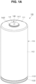
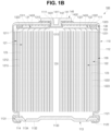
- FIGS. 1A and 1B respectively illustrate perspective and cross-sectional views of a secondary battery 100 according to embodiments.
- the secondary battery 100 may include a case 110, an electrode assembly 120, a current collector plate assembly 130, and a terminal (e.g., rivet terminal 140).
- the case 110 may be provided in a substantially cylindrical shape.
- the case 110 may include a rivet plate 111 having a substantially disk shape with a terminal hole 1111 at a center thereof, a sidewall 112 extending downwardly from the rivet plate 111, and a finish plate 113 that blocks a lower end of the sidewall 112.
- the case 110 may include, or may be referred to as, a can, a housing, or an exterior.
- the case 110 may include steel, a steel alloy, nickel-plated steel, aluminum, an aluminum alloy, copper, or a copper alloy.
- the case 110 may be manufactured through a deep drawing process in which a metal plate is placed on a die having an opening, and is pressed by a punch to manufacture a cylindrical case, an extrusion process in which molten metal is put into an extrusion die and extruded into a pipe-shape case, or a bending and welding process in which a thin metal plate is rolled to be bent and welded so as to manufacture a case.
- the case 110 may accommodate the electrode assembly 120, the current collector plate assembly 130, and an electrolyte, which may be optional, to isolate the components from external environments.
- the rivet plate 111 and the sidewall 112 may be provided in one body. In some embodiments, the rivet plate 111 and the sidewall 112 may be provided separately and then coupled and welded to each other. In some embodiments, the sidewall 112 and the finish plate 113 may be provided in one body. In some embodiments, the sidewall 112 and the finish plate 113 may be provided separately and then welded and coupled to each other (e.g., a beadless design).
- an inwardly recessed beading part 1121 and an inwardly bent crimping part 1122 may be optionally provided in a lower end of the sidewall 112.
- the finish plate 113 may be coupled between the beading part 1121 and the crimping part 1122.
- an insulating gasket 114 may be disposed (e.g. located) on the beading part 1121 and the crimping part 1122, and the finish plate 113 may be coupled in the state in which the insulating gasket 114 is interposed between the beading part 1121 and the crimping part 1122.
- the finish plate 113 may be directly welded and coupled to the sidewall 112, or the finish plate 113 may be coupled to the sidewall 112 in a curling or seaming manner.
- the finish plate 113 may include a relatively thin vent notch 1134 in an upper surface thereof.
- the finish plate 113 may include a peripheral area 1131 that is sandwiched between the beading part 1121 and the crimping part 1122, an inner area 1132 connected to the peripheral area 1131 and lower than the peripheral area 1131, and a central area 1133 connected to the inner area 1132 and higher than the inner area 1132.
- the vent notch 1134 may be provided in the inner area 1132.
- the central area 1133 may be closer to the electrode assembly 120 than the peripheral area 1131 and the inner area 1132.
- the vent notch 1134 may include, or may be referred to as, a safety vent. This vent notch 1134 may be broken if an internal pressure of the secondary battery is higher than a reference pressure to release an internal gas.
- the electrode assembly 120 may be provided in a substantially cylindrical shape.
- the electrode assembly 120 may be wound into a cylindrical shape and then coupled to the case 110.
- the electrode assembly 120 may include, or may be referred to as, an electrode group or a jelly roll.
- the electrode assembly 120 may include a first electrode plate 121 (e.g., a positive electrode plate), a second electrode plate 122 (e.g., a negative electrode plate), and a separator 123.
- the first electrode plate 121 e.g., the positive electrode plate
- the separator 123, and the second electrode plate 122 e.g., the negative electrode plate
- the first electrode plate 121 may include a plurality of first tabs 1211 extending upwardly.
- the second electrode plate 122 may include a plurality of second tabs 1221 extending upwardly.
- the upward direction may be defined as a first direction
- the downward direction, which is opposite to the upward direction may be defined as a second direction.
- the first electrode plate 121 may be provided by applying a first active material 1213, such as transition metal oxide, to a first current collector 1212 made of metal foil, such as aluminum, and may include a first tab 1211 (e.g., an area that is not coated with the first active material 1213) extending and protruding toward an upper side of the first current collector 1212.
- the first tab 1211 extending and protruding as described above may be referred to as a first non-coating portion tab or a first base material tab, and the first tab 1211 may be aligned at the same or similar position through a winding process, a base material punching process, or a base material notching process to constitute a multi-tab.
- the first tab 1211 may include a lead tab that is separately provided and welded to the first current collector 1212.
- a compound capable of reversible intercalation and deintercalation of lithium may be used as the first active material.
- one or more types of complex oxides of lithium and a metal selected from cobalt, manganese, nickel, iron, or combinations thereof may be used.
- the complex oxides may be lithium transition metal complex oxide, and examples may include lithium nickel-based oxide, lithium cobalt-based oxide, lithium manganese-based oxide, lithium iron phosphate-based compound, cobalt-free nickel-manganese-based oxide, or a combination thereof.
- a compound represented by any one of the following chemical formulas may be used: LiaA1-bXbO2-cDc(0.90 ⁇ a ⁇ 1.8, 0 ⁇ b ⁇ 0.5, 0 ⁇ c ⁇ 0.05); LiaMn2-bXbO4-cDc(0.90 ⁇ a ⁇ 1.8, 0 ⁇ b ⁇ 0.5, 0 ⁇ c ⁇ 0.05); LiaNi1-b-cCobXcO2- ⁇ D ⁇ (0.90 ⁇ a ⁇ 1.8, 0 ⁇ b ⁇ 0.5, 0 ⁇ c ⁇ 0.5, 0 ⁇ 2); LiaNi1-b-cMnbXcO2- ⁇ D ⁇ (0.90 ⁇ a ⁇ 1.8, 0 ⁇ b ⁇ 0.5, 0 ⁇ c ⁇ 0.5, 0 ⁇ 2); LiaNibCocL1dGeO2(0.90 ⁇ a ⁇ 1.8, 0 ⁇ b ⁇ 0.9, 0 ⁇ c ⁇ 0.5, 0 ⁇ d ⁇ 0.5, 0 ⁇ e ⁇ 0.1); LiaNiGbO2(0.90 ⁇ a ⁇ 1.8, 0.001 ⁇ b ⁇ 0.1
- A may be Ni, Co, Mn, or a combination thereof
- X may be Al, Ni, Co, Mn, Cr, Fe, Mg, Sr, V, a rare earth element, or a combination thereof
- D may be O, F, S, P, or a combination thereof
- G may be Al, Cr, Mn, Fe, Mg, La, Ce, Sr, V, or a combination thereof
- L1 may be Mn, Al, or a combination thereof.
- a positive electrode for a lithium secondary battery may include a current collector (e.g., a first current collector) and a positive electrode active material layer (e.g., a first active material layer) disposed (e.g. located) on the current collector.
- the positive electrode active material layer may include a positive electrode active material, and may further include a binder and/or a conductive material.
- a content of the positive electrode active material may be about 90% to about 99.5% by weight based on 100% by weight of the positive electrode active material layer, and a content of each of the binder and the conductive material may be about 0.5% to 5% or about 5% by weight based on 100% by weight of the positive electrode active material layer.
- the first tab 1211 may be electrically connected to the first current collector plate 131 and to the terminal (e.g., the rivet terminal 140) to provide a path for a current flow between the first electrode plate 121 and the rivet terminal 140.
- the second electrode plate 122 may be provided by applying a second active material 1223, such as graphite or carbon, to a second current collector 1222 made of metal foil, such as copper or nickel, and may include a second tab 1221 (e.g., an area that is not coated with the second active material 1223) that extends and protrudes toward an upper side of the second current collector 1222.
- the second tab 1221 extending and protruding as described above may be referred to as a second non-coating portion tab or a second base material tab, and the second tab 1221 may be aligned at the same or similar position through a winding process, a base material punching process, or a base material notching process to constitute a multi-tab.
- the second tab 1221 may include a lead tab that is separately provided and welded to the second current collector 1222.
- the second tab 1221 may be electrically connected to the second terminal (e.g., the case 110) to provide a path for current flow between the second electrode plate 122 and the case 110.
- the second active material may include a material capable of reversibly intercalating/deintercalating lithium ions, a lithium metal, an alloy of the lithium metal, a material capable of doping and dedoping lithium, or transition metal oxide.
- the material capable of reversibly intercalating/deintercalating lithium ions may be a carbon-based negative electrode active material, and may include, for example, crystalline carbon, amorphous carbon, or a combination thereof.
- the crystalline carbon may include graphite, such as natural graphite or artificial graphite
- examples of the amorphous carbon may include soft carbon, hard carbon, mesophase pitch carbide, calcined coke, etc.
- a Si-based negative electrode active material or an Sn-based negative electrode active material may be used as the material capable of doping and dedoping lithium.
- the Si-based negative electrode active material may be silicon, silicon-carbon composite, SiOx (0 ⁇ x ⁇ 2), an Si-based alloy, or a combination thereof.
- the silicon-carbon composite may be a composite of silicon and amorphous carbon. According to some embodiments, the silicon-carbon composite may be in the form of silicon particles and amorphous carbon coated on a surface of each silicon particle.
- the silicon-carbon composite may further include crystalline carbon.
- the silicon-carbon composite may include a core containing crystalline carbon and silicon particles, and an amorphous carbon coating layer disposed (e.g. located) on a surface of the core.
- a negative electrode for the lithium secondary battery may include a current collector (e.g., a second current collector) and a negative electrode active material layer (e.g., a second active material layer) disposed (e.g. located) on the current collector.
- the negative electrode active material layer includes a negative electrode active material, and may further include a binder and/or a conductive material.
- the negative electrode active material layer may include about 90% to about 99% by weight of the negative electrode active material, about 0.5% to about 5% by weight of the binder, and about 0% to about 5% by weight of the conductive material.
- the binder may be a non-aqueous binder, an aqueous binder, a dry binder, or a combination thereof. If the aqueous binder is used as the negative electrode binder, the negative electrode binder may further include a cellulose-based compound capable of imparting viscosity.
- the separator 123 may be interposed between the first electrode plate 121 and the second electrode plate 122 to reduce or prevent the likelihood of a short circuit between the first electrode plate 121 and the second electrode plate 122, and to enable movement of lithium ions.
- the separator 123 may be slightly wider than the surface area of each of the first electrode plate 121 and the second electrode plate 122 to further protrude in upward, downward, left, and/or right directions than each of the first electrode plate 121 and the second electrode plate 122.
- the separator 123 may reduce or prevent the likelihood of the first electrode plate 121 and the second electrode plate 122 being in direct contact with the case 110 in the upward, downward, left, and/or right directions of the electrode assembly 120.
- the separator 123 may protrude and extend by a corresponding length in the upward and/or downward directions of the electrode assembly 120 without the first tab 1211 and the second tab 1221.
- the electrode assembly 120 may be approximately hollow in the central area, which may also be referred to as the core 124.
- the core 124 may serve as a passage through which a pressure is discharged if an internal pressure of the secondary battery becomes greater than a reference pressure.
- the internal pressure may be applied to the finish plate 113 through the core 124 to break the vent notch 1134 of the finish plate 113, thereby reducing the internal pressure.
- the electrode assembly 120 may be accommodated in the case 110 together with the electrolyte.
- the electrolyte may include an organic solvent, such as ethylene carbonate (EC), propylene carbonate (PC), diethyl carbonate (DEC), ethylmethyl carbonate (EMC), and/or dimethyl carbonate (DMC), and lithium salt, such as LiPF6 or LiBF4.
- the electrolyte may be liquid, solid, or gel.
- the current collector plate assembly 130 may include a first current collector plate 131 and a second current collector plate 132.
- the current collector plate assembly 130 may further include an insulating plate 133.
- the first current collector plate 131 may electrically connect the first electrode plate 121 of the electrode assembly 120 to the rivet terminal 140.
- the first current collector plate 131 may include, or may be referred to as, a current collector, a conductor, or a conductive lead.
- the first current collector plate 131 may be made of aluminum or an aluminum alloy.
- the first current collector plate 131 may be manufactured by punching a metal plate using a die and a punch, or by casting a molten metal.
- the first current collector plate 131 may include a first current collector plate first connection area 1311, a first current collector plate connection area 1312, and a first current collector plate second connection area 1313.
- the first current collector plate first connection area 1311 may be electrically connected to the plurality of first tabs 1211 described above through a method such as laser welding.
- the first current collector plate connection area 1312 may be bent and may extend upwardly from the first current collector plate first connection area 1311.
- the first current collector plate second connection area 1313 may be bent and may extend from the first current collector plate connection area 1312, and may be electrically connected to the rivet terminal 140 through a method such as laser welding.
- the first current collector plate 131 may become a current flow path between the electrode assembly 120 and the rivet terminal 140.
- the second current collector plate 132 may electrically connect the second electrode plate 122 of the electrode assembly 120 to the case 110 (for example, the rivet plate 111).
- the second current collector plate 132 may include, or may be referred to as, a current collector, a conductor, or a conductive lead.
- the second current collector plate 132 may be made of copper, a copper alloy, nickel, or a nickel alloy.
- the second current collector plate 132 may be manufactured by punching a metal plate using a die and a punch, or by casting a molten metal.
- the second current collector plate 132 may include a second current collector plate first connection area 1321, a second current collector plate connection area 1322, and a second current collector plate second connection area 1323.
- the second current collector plate first connection area 1321 may be electrically connected to the plurality of second tabs 1221 described above through a method, such as laser welding.
- the second current collector plate connection area 1322 may be bent, and may extend upwardly from the second current collector plate first connection area 1321.
- the second current collector plate second connection area 1323 may be bent, and may extend from the second current collector plate connection area 1322 and may be electrically connected to the case 110 (e.g., to the rivet plate 111) through a method, such as laser welding.
- the second current collector plate 132 may become a current flow path between the electrode assembly 120 and the case 110.
- the insulating plate 133 may be interposed between the first and second current collector plates 131 and 132. In some embodiments, a portion of the insulating plate 133 may be interposed between the first current collector plate first connection area 1311 and the second current collector plate second connection area 1323 to reduce or prevent the likelihood of the first current collector plate 131 and the second current collector plate 132 being electrically short-circuited with each other. In some embodiments, a portion of the insulating plate 133 may be interposed between the second current collector plate second connection area 1323 and the electrode assembly 120.
- the insulating plate 133 may include, or may be referred to as, an insulator, an insulating block, or an insulating facer.
- the insulating plate 133 may be made of polypropylene, polyethylene, double synthetic rubber (EPDM), or nylon that does not react with the electrolyte.
- the first current collector plate 131, the second current collector plate 132, and the insulating plate 133 may be manufactured through a double injection method.
- the rivet terminal 140 may pass through the case 110. In some embodiments, the rivet terminal 140 may pass through a terminal hole 1111 provided in the rivet plate 111. In some embodiments, an insulating gasket 1431 may be interposed between the rivet terminal 140 and the terminal hole 1111. In some embodiments, the rivet terminal 140 may include a relatively wide head part 141 and a relatively narrow body part 142 extending downwardly from the head part 141 to pass through the terminal hole 1111. In some embodiments, the rivet terminal 140 may further include a recess 1411 receding at a corresponding depth from an upper surface of the head part 141 toward the body part 142.
- a thickness between a bottom surface of the body part 142 and a corresponding lowest surface may become relatively thin due to the recess 1411, and energy of a laser beam may be smoothly transmitted to the first current collector plate 131 (e.g., the first current collector plate second connection area 1313) so that the rivet terminal 140 and the first current collector plate 131 are welded to each other through laser welding.
- an upper insulator 1432 may be further interposed between the head part 141 and the rivet plate 111.
- a lower insulator 1433 may be further interposed around the body part 142 passing through the rivet plate 111.
- the lower insulator 1433 may be interposed between the current collector plate assembly 130 and rivet plate 111.
- the recess 1411 may be finished with a generally flat member (e.g., metal) after the welding process.
- a metal member may be coupled to the recess 1411, or may close an upper end of the recess 1411.
- the present disclosure may provide the secondary battery 100 in which the first tab 1211 (e.g., the positive electrode tab) and the second tab 1221 (e.g., the negative electrode tab) of the electrode assembly 120 are provided in the same direction (e.g., the upward direction) so as to be electrically connected to the first terminal (e.g., the rivet terminal 140) and the second terminal (e.g., the case 110) so that the electrical resistance is low, and so that the current path is short.
- the first tab 1211 e.g., the positive electrode tab
- the second tab 1221 e.g., the negative electrode tab
- the present disclosure may provide the secondary battery 100 in which the first tab 1211 (e.g., the positive electrode tab) and the second tab 1221 (e.g., the negative electrode tab) of the electrode assembly 120 are provided in the same direction (e.g., the upward direction) so as to be electrically connected to the first terminal (e.g., the rivet terminal 140) and the second terminal (e.g., the case 110
- the present disclosure may provide the secondary battery 100 in which the first current collector plate 131 (e.g., the positive electrode current collector plate) and the second current collector plate 132 (e.g., the negative electrode current collector plate) are three-dimensionally coupled and provided on the same area to occupy a relatively small volume in the internal space of the case 110 so that the relatively large electrode assembly 120 is accommodated in the case 110.
- the first current collector plate 131 e.g., the positive electrode current collector plate
- the second current collector plate 132 e.g., the negative electrode current collector plate
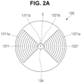
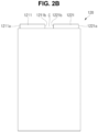
- FIGS. 2A and 2B respectively illustrate plan and side views of the electrode assembly 120 in the secondary battery 100 according to embodiments.
- the electrode assembly 120 may include a plurality of first tabs 1211 and a plurality of second tabs 1221, which protrude and extend upwardly.
- the plurality of first tabs 1211 and the plurality of second tabs 1221 may be provided in shapes that are symmetrical to each other about the central core 124 (e.g., an empty space).
- the plurality of first tabs 1211 may have a planar circular sector shape or planar fan shape with a center C, an outer arc 1211a, and an inner arc 1211b.
- a length of the outer arc 1211a may be longer than that of the inner arc 1211b.
- a central angle of the number of first tabs 1211 may be in a range of about 10 degrees to about 180 degrees, in a range of about 40 degrees to about 160 degrees, or in a range of about 80 degrees to about 120 degrees.
- the first tabs 1211 may be in contact with the second tabs 1221, and if the central angle of the plurality of first tabs 1211 is less than about 10 degrees, a contact area or welding area with the first current collector plate 131 may be relatively small.
- the plurality of first tabs 1211 may have a substantially rectangular planar shape. In some embodiments, the plurality of first tabs 1211 may have a rectangular shape with a center C, an outer arc 1211a, and an inner arc 1211b.
- the plurality of second tabs 1221 may be provided at opposing positions that are spaced apart from the plurality of first tabs 1211, and the plane may have a circular sector or a fan shape with a center C, an outer arc 1221a, and an inner arc 1221b.
- a length of the outer arc 1221a may be longer than that of the inner arc 1221b.
- a central angle of the number of second tabs 1221 may be in a range of about 10 degrees to about 180 degrees, in a range of about 40 degrees to about 160 degrees, or in a range of about 80 degrees to about 120 degrees.
- the second tabs 1221 may be in contact with the first tabs 1211, and if the central angle of the plurality of second tabs 1221 is less than about 10 degrees, a contact area or welding area with the second current collector plate 132 may be relatively small.
- the plurality of second tabs 1221 may have a substantially rectangular planar shape.
- the plurality of second tabs 1221 may have a rectangular shape with a center C, an outer arc 1221a, and an inner arc 1221b.
- FIGS. 3A and 3b respectively illustrate cross-sectional and plan views of the current collector plate assembly 130 in the secondary battery 100 according to embodiments
- FIGS. 3C and 3D respectively illustrate plan views of the first current collector plate 131 and the second current collector plate 132 in the current collector plate assembly 130 according to embodiments.
- the current collector plate assembly 130 may include a first current collector plate 131, a second current collector plate 132, and an insulating plate 133 (optional).
- the first current collector plate 131 may include a first current collector plate first connection area 1311, a first current collector plate connection area 1312, and a first current collector plate second connection area 1313.
- the first current collector plate first connection area 1311 may be a planar circular sector shape or a planar fan shape with a center C, an outer arc 1311a, and an inner arc 1311b. A length of the outer arc 1311a may be longer than that of the inner arc 1311b.
- the first current collector plate second connection area 1313 may have a disk shape with a center.
- a plurality of welding lines WL may be provided in a straight line on the first current collector plate first connection area 1311, and the first tab 1211 and the first current collector plate first connection area 1311 may be electrically connected to each other by the welding lines WL.
- the first tab 1211 may be compacted or bent in an inward or outward direction, and may be welded to the first current collector plate first connection area 1311.
- the plurality of welding lines WL may be provided in a ring shape on the first current collector plate second connection area 1313, and the rivet terminal 140 and the first current collector plate second connection area 1313 may be electrically connected to each other by the welding lines WL.
- the planar shape of the first current collector plate first connection area 1311 may be the same as or similar to that of the first tab 1211. In some embodiments, the first current collector plate first connection area 1311 may overlap the first tab 1211.
- the second current collector plate 132 may include a second current collector plate first connection area 1321, a second current collector plate connection area 1322, and a second current collector plate second connection area 1323.
- the second current collector plate first connection area 1321 may be a planar circular sector shape or planar fan shape with a center C, an outer arc 1321a, and an inner arc 1321b. In some embodiments, the second current collector plate first connection area 1321 may be symmetrical to the first current collector plate first connection area 1311 with respect to the core 124 of the electrode assembly 120 or with respect to the first current collector plate second connection area 1313. In some embodiments, the second current collector plate second connection area 1323 may be in the form of a circular ring plate having a center. In some embodiments, the center C of the second current collector plate second connection area 1323 may coincide with the center C of the core of the electrode assembly 120 or with the center C of the first current collector plate second connection area 1313.
- a partial area of the second current collector plate second connection area 1323 may overlap a partial area of the first current collector plate first connection area 1311 in a vertical direction.
- a partial area of the insulating plate 133 may be interposed between the overlapping areas, such as between the partial area of the first current collector plate first connection area 1311 and the partial area of the second current collector plate second connection area 1323.
- a partial area of the insulating plate 133 may also be provided between the second current collector plate second connection area 1323 and the electrode assembly 120.
- a plurality of welding lines WL may be provided in a straight line on the second current collector plate first connection area 1321, and the second tab 1221 and the second current collector plate first connection area 1321 may be electrically connected to each other by the welding lines WL.
- the second tab 1221 may be compacted or bent in an inward or outward direction, and may be welded to the second current collector plate first connection area 1321.
- the plurality of welding lines WL may be provided in the form of a circular dotted line in the second current collector plate second connection area 1323, and the case 110 (e.g., the rivet plate 111) and the second current collector plate second connection area 1323 may be electrically connected to each other by the welding lines WL.
- the planar shape of the second current collector plate first connection area 1321 may be the same as or similar to that of the second tab 1211. In some embodiments, the second current collector plate first connection area 1321 may overlap the second tab 1211.
- the first current collector plate first connection area 1311 and the second current collector plate first connection area 1321 may be disposed (e.g. located) on the same or similar plane, and the first current collector plate second connection area 1313 may be closer (e.g. disposed closer) to the electrode assembly 120 than the second current collector plate second connection area 1323.
- the current collector plate assembly 130 may be provided to have a relatively compact thickness to occupy a relatively small volume inside the secondary battery 100.
- a relatively large electrode assembly 120 may be provided inside the secondary battery 100.
- FIG. 4 illustrates a schematic view of a laser welding method in a secondary battery 100 according to embodiments.
- laser beam may be provided to a recess 1411 of a rivet terminal 140 so that a body part 142 of the rivet terminal 140 is electrically connected to a first current collector plate first connection area 1311.
- the laser beam may be provided in the form of an approximately circular dotted line along a circumference of the case 110 (e.g., the rivet plate 111) so that the rivet plate 111 is electrically connected to a second current collector plate second connection area 1323.
- a first current path may be provided through the first terminal (e.g., the rivet terminal 140), a first current collector plate 131, and a first electrode plate 121.
- a second current path may be provided through a second terminal (e.g., the case 110 or the rivet plate 111), a second current collector plate 132, and a second electrode plate 122.
- the first current path and the second current path which are relatively short, may be provided to reduce internal electrical resistance of the secondary battery 100.
- FIG. 5 illustrates a cross-sectional view of a secondary battery according to embodiments.
- a secondary battery 200 illustrated in FIG. 5 may be similar to the secondary battery 100 illustrated in FIGS. 1A and 1B , except that a liquid injection port 1134 and a plug 210 are provided in a finish plate 113.
- the liquid injection port 1134 may be provided in the finish plate 113, for example, in a central area 1133, and the liquid injection port 1134 may be closed due to the plug 210.
- an electrolyte may be injected through the liquid injection port 1134, and the liquid injection port 1134 may be blocked by the plug 210 to reduce or prevent the likelihood of the electrolyte leaking.
- the liquid injection port and the plug may be provided on the rivet plate 111.
- FIG. 6 illustrates a cross-sectional view of the secondary battery 300 according to embodiments.
- a secondary battery 300 illustrated in FIG. 6 may be similar to the secondary battery 100 illustrated in FIGS. 1A and 1B , except that a conductive ring plate 310 is further provided.
- the conductive ring plate 310 may be mechanically/electrically attached to a partial area of a case 110 surrounding a rivet terminal 140 (e.g., to a rivet plate 111).
- the conductive ring plate 310 may be welded to the rivet plate 111 by laser beam.
- the conductive ring plate 310 may be made of a material similar to or the same as the rivet plate 111.
- a top surface of the conductive ring plate 310 may be similar to or may form the same plane as a top surface of the rivet terminal 140.
- busbars connected to the rivet terminal 140 and the conductive ring plate 310 may have the same height.
- the top surface of the conductive ring plate 310 may be lower than the top surface of the rivet terminal 140.
- the busbars connected to the rivet terminal 140 and the conductive ring plate 310 may have different heights.
- the present disclosure may provide the conductive ring plate 310 on a second terminal (e.g., the rivet plate 111 of the case 110) to provide the secondary battery 300 having excellent flatness between the first terminal (e.g., the rivet terminal 140) and the second terminal (e.g. case 110).
- a second terminal e.g., the rivet plate 111 of the case 110
- the present disclosure may provide the conductive ring plate 310 on a second terminal (e.g., the rivet plate 111 of the case 110) to provide the secondary battery 300 having excellent flatness between the first terminal (e.g., the rivet terminal 140) and the second terminal (e.g. case 110).
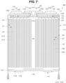
- FIG. 7 illustrates a cross-sectional view of the secondary battery according to embodiments.
- a secondary battery 400 illustrated in FIG. 7 may be similar to the secondary battery 100 illustrated in FIGS. 1A and 1B , except that a finish plate 113 is welded and fixed to a sidewall 112 of a case 110.
- the finish plate 113 may be fixed to the sidewall 112 of the case 110 by laser welding.
- the laser beam may be irradiated onto a portion at which a circumference of the finish plate 113 and the sidewall 112 are in contact with each other.
- a beadless secondary battery 400 may be provided to remove a space that is occupied by a beading part and a crimping part.
- the present disclosure may accommodate the relatively larger electrode assembly 120 in the case 110 to provide the secondary battery 400 having relatively high capacity.
- a first tab e.g., positive electrode tab
- a second tab e.g., negative electrode tab
- first terminal e.g., rivet terminal
- second terminal e.g., the case 110
- the present disclosure may provide the secondary battery in which the first current collector plate (e.g., positive electrode current collector plate) and the second current collector plate (e.g., negative electrode current collector plate) are three-dimensionally coupled and provided at the same general area to occupy the relatively small volume in the internal space of the case so that the relatively large electrode assembly is accommodated in the case.
- first current collector plate e.g., positive electrode current collector plate
- second current collector plate e.g., negative electrode current collector plate
- the present disclosure may provide the secondary battery in which the conductive ring plate is provided on the second terminal (e.g., the case 110) to realize the excellent flatness between the first terminal (e.g., rivet terminal) and the second terminal.
- the conductive ring plate is provided on the second terminal (e.g., the case 110) to realize the excellent flatness between the first terminal (e.g., rivet terminal) and the second terminal.
Landscapes
- Chemical & Material Sciences (AREA)
- Chemical Kinetics & Catalysis (AREA)
- Electrochemistry (AREA)
- General Chemical & Material Sciences (AREA)
- Engineering & Computer Science (AREA)
- Manufacturing & Machinery (AREA)
- Connection Of Batteries Or Terminals (AREA)
Abstract
A secondary battery (100) includes a case, an electrode assembly (120) in the case, and including first tabs (1211) protruding in a first direction, and second tabs (1221) protruding in the first direction, a first current collector plate (131) electrically connected to the first tabs, a second current collector plate (132) electrically connecting the second tabs to the case, and a rivet terminal (140) electrically connected to the first current collector plate and passing through the case.
Description
- Embodiments relate to a secondary battery.
- Secondary batteries are rechargeable, unlike primary batteries. In these secondary batteries, a low capacity battery including a battery cell in the form of a pack may be used in portable small electronic devices, such as smartphones and digital cameras, and a high capacity battery module including tens to hundreds of battery packs connected to each other, may be used as a power source for driving motors (e.g., motors of hybrid vehicles, electric vehicles, and/or the like).
- A rechargeable secondary battery includes an electrode assembly, in which a separator is interposed between a positive electrode plate and a negative electrode plate, a current collector plate electrically connected to the electrode assembly, a terminal electrically connected to the current collector plate, and a case that accommodates the electrode assembly and the current collector plate and through which the terminal passes to be coupled thereto.
- The above-described information serves as the background of the present disclosure, and is only for improving understanding of the background of the present disclosure, and thus may include information that does not constitute the related art.
- Aspects of some embodiments of the present disclosure provide a secondary battery in which a first tab (e.g., positive electrode tab) and a second tab (e.g., negative electrode tab) of an electrode assembly are provided in the same direction so as to be electrically connected to a first terminal (e.g., rivet terminal) and a second terminal (e.g., case) so that electrical resistance is low, and so that a current path is short.
- Other aspects of some embodiments of the present disclosure provide a secondary battery in which a first current collector plate (e.g., positive electrode current collector plate) and a second current collector plate (e.g., negative electrode current collector plate) are three-dimensionally coupled and provided on the same area to occupy a relatively small volume in an internal space of a case, so that a relatively large electrode assembly is accommodated in the case.
- Other aspects of some embodiments of the present disclosure provide a secondary battery in which a conductive ring plate is provided on a second terminal (e.g., case) to realize excellent flatness between a first terminal (e.g., rivet terminal) and the second terminal.
- According to some embodiments, a secondary battery includes: a case (e.g. a cylindrical case); an electrode assembly in (e.g. accommodated in) the case, and with (e.g. provided with) a plurality of first tabs that protrude in a first direction, and a plurality of second tabs that protrude in the first direction; a first current collector plate in the case and electrically connected to the plurality of first tabs; a second current collector plate configured to electrically connect the plurality of second tabs to the case; and a rivet terminal electrically connected to the first current collector plate and passing through the case.
- The plurality of first tabs may have a planar circular sector having a center, an outer arc, and an inner arc, or may have a planar rectangular shape.
- A central angle of the first tabs may be less than about 180 degrees.
- The second tabs may be spaced apart from the first tabs, and may have a planar circular sector having a center, an outer arc, and an inner arc, or may have a planar rectangular shape.
- A central angle of the second tabs may be less than about 180 degrees.
- The first current collector plate may include a first current collector plate first connection area electrically connected to the first tabs, a first current collector plate connection area bent and extending from the first current collector plate first connection area, and a first current collector plate second connection area bent and extending from the first current collector plate connection area, and electrically connected to the rivet terminal.
- The first current collector plate first connection area may have a planar circular sector having a center, an outer arc, and an inner arc, wherein the first current collector plate second connection area has a disk shape with a center.
- The second current collector plate may include a second current collector plate first connection area electrically connected to the second tabs, a second current collector plate connection area bent and extending from the second current collector plate first connection area, and a second current collector plate second connection area bent and extending from the second current collector plate connection area, and electrically connected to the case.
- The second current collector plate first connection area may have a planar circular sector having a center, an outer arc, and an inner arc, wherein the second current collector plate second connection area has a circular ring plate shape with a center.
- The secondary battery may further include an insulating plate between the first current collector plate and the second current collector plate, and having a partial area in a gap between the second current collector plate and the electrode assembly.
- The secondary battery may further include a conductive ring plate coupled to a partial area of the case around the rivet terminal.
- The first current collector plate may include a first current collector plate first connection area electrically connected to the first tabs, a first current collector plate connection area bent and extending from the first current collector plate first connection area in the first direction, and a first current collector plate second connection area bent and extending from the first current collector plate connection area, and electrically connected to the rivet terminal, wherein the second current collector plate includes a second current collector plate first connection area electrically connected to the second tabs, a second current collector plate connection area bent and extending from the second current collector plate first connection area in the first direction, and a second current collector plate second connection area bent and extending from the second current collector plate connection area, and electrically connected to the case.
- The first current collector plate first connection area and the second current collector plate first connection area may be on a same plane, wherein the first current collector plate second connection area is closer to the electrode assembly than the second current collector plate second connection area.
- A partial area of the second current collector plate second connection area may overlap the first current collector plate first connection area.
- The case may include a rivet plate coupled to the rivet terminal, a sidewall extending integrally from the rivet plate in a second direction that is opposite to the first direction, and a finish plate configured to block an end of the sidewall.
- The finish plate may include a safety vent.
- The finish plate may be fixed to the sidewall by a beading part and a crimping part provided on the sidewall.
- The finish plate may be fixed to the sidewall by welding.
- The case may include a rivet plate coupled to the rivet terminal, a sidewall welded to the rivet plate and extending in a second direction that is opposite to the first direction, and a finish plate extending integrally from the sidewall.
- The finish plate may include a safety vent.
- At least some of the above and other features of the invention are set out in the claims.
- The accompanying drawings are included to provide a further understanding of the present disclosure, and are incorporated in and constitute a part of this specification. The drawings illustrate embodiments of the present disclosure and, together with the description, serve to explain aspects of the present disclosure. In the drawings:
-
FIGS. 1A and1B respectively illustrate perspective and cross-sectional views of a secondary battery according to embodiments; -
FIGS. 2A and2B respectively illustrate plan and side views of an electrode assembly in the secondary battery according to embodiments; -
FIGS. 3A and 3b respectively illustrate cross-sectional and plan views of a current collector plate assembly in the secondary battery according to embodiments; -
FIGS. 3C and 3D respectively illustrate plan views of a first current collector plate and a second current collector plate in the current collector plate assembly according to embodiments; -
FIG. 4 illustrates a schematic view of a laser welding method in a secondary battery according to embodiments; -
FIG. 5 illustrates a cross-sectional view of a secondary battery according to embodiments; -
FIG. 6 illustrates a cross-sectional view of the secondary battery according to embodiments; and -
FIG. 7 illustrates a cross-sectional view of the secondary battery according to embodiments. - Hereinafter, embodiments will be described in detail with reference to the accompanying drawings.
- The present disclosures may, however, be embodied in many different forms and should not be construed as being limited to the embodiments set forth herein; rather, these embodiments are provided so that those skilled in the art thoroughly understand the present disclosure. Rather, these embodiments are provided so that this disclosure will be thorough and complete, and will fully convey the scope of the present disclosure to those skilled in the art.
- In addition, in the following drawings, the thickness or size of each layer is exaggerated for convenience and clarity of description, and the same reference numerals in the drawings refer to the same elements. As used herein, the term "and/or" includes any and all combinations of one or more of the associated listed items. In this specification, it will also be understood that if a member A is referred to as being connected to a member B, the member A can be directly connected to the member B or indirectly connected to the member B with a member B therebetween.
- The terms used in this specification are for illustrative purposes of the present disclosure only and should not be construed to limit the meaning or the scope of the present disclosure. As used in this specification, a singular form may, unless definitely indicating a particular case in terms of the context, include a plural form. Also, the expressions "comprise/include" and/or "comprising/including" used in this specification neither define the mentioned shapes, numbers, steps, operations, members, elements, and/or groups of these, nor exclude the presence or addition of one or more other different shapes, numbers, steps, operations, members, elements, and/or groups of these, or addition of these. The term "and/or" used herein includes any and all combinations of one or more of the associated listed items.
- As used herein, terms such as "first," "second," etc. are used to describe various members, components, areas, layers, and/or portions. However, it is obvious that the members, components, areas, layers, and/or portions should not be defined by these terms. The terms do not mean a particular order, up and down, or superiority, and are used only for distinguishing one member, component, region, layer, or portion from another member, component, region, layer, or portion. Thus, a first member, component, region, layer, or portion which will be described may also refer to a second member, component, region, layer, or portion, without departing from the teaching of the present disclosure.
- Spatially relative terms, such as "bottom", "beneath", "below", "lower", "above", "upper" and the like, may be used herein for ease of description to describe one element or feature's relationship to another element(s) or feature(s) as illustrated in the drawings. These spatially relative terms are intended for easy comprehension of the prevent invention according to various process states or usage states of the prevent invention, and thus, the present disclosure is not limited thereto. For example, an element or feature shown in the drawings is turned inside out, the element or feature described as "bottom", "beneath", or "below" may change into "above" or "upper". Thus, the terms "bottom" and "beneath" may encompass the term "above" or "below".
-
FIGS. 1A and1B respectively illustrate perspective and cross-sectional views of asecondary battery 100 according to embodiments. As illustrated inFIGS. 1A and1B , thesecondary battery 100 according to embodiments may include acase 110, anelectrode assembly 120, a currentcollector plate assembly 130, and a terminal (e.g., rivet terminal 140). - The
case 110 may be provided in a substantially cylindrical shape. Thecase 110 may include arivet plate 111 having a substantially disk shape with aterminal hole 1111 at a center thereof, asidewall 112 extending downwardly from therivet plate 111, and afinish plate 113 that blocks a lower end of thesidewall 112. Thecase 110 may include, or may be referred to as, a can, a housing, or an exterior. Thecase 110 may include steel, a steel alloy, nickel-plated steel, aluminum, an aluminum alloy, copper, or a copper alloy. Thecase 110 may be manufactured through a deep drawing process in which a metal plate is placed on a die having an opening, and is pressed by a punch to manufacture a cylindrical case, an extrusion process in which molten metal is put into an extrusion die and extruded into a pipe-shape case, or a bending and welding process in which a thin metal plate is rolled to be bent and welded so as to manufacture a case. Thecase 110 may accommodate theelectrode assembly 120, the currentcollector plate assembly 130, and an electrolyte, which may be optional, to isolate the components from external environments. - In some embodiments, the
rivet plate 111 and thesidewall 112 may be provided in one body. In some embodiments, therivet plate 111 and thesidewall 112 may be provided separately and then coupled and welded to each other. In some embodiments, thesidewall 112 and thefinish plate 113 may be provided in one body. In some embodiments, thesidewall 112 and thefinish plate 113 may be provided separately and then welded and coupled to each other (e.g., a beadless design). - In some embodiments, an inwardly recessed
beading part 1121 and an inwardly bent crimpingpart 1122 may be optionally provided in a lower end of thesidewall 112. In some embodiments, thefinish plate 113 may be coupled between thebeading part 1121 and the crimpingpart 1122. In some embodiments, an insulatinggasket 114 may be disposed (e.g. located) on thebeading part 1121 and the crimpingpart 1122, and thefinish plate 113 may be coupled in the state in which the insulatinggasket 114 is interposed between thebeading part 1121 and the crimpingpart 1122. As described above, instead of providing thebeading part 1121 and the crimpingpart 1122, thefinish plate 113 may be directly welded and coupled to thesidewall 112, or thefinish plate 113 may be coupled to thesidewall 112 in a curling or seaming manner. - In some embodiments, the
finish plate 113 may include a relativelythin vent notch 1134 in an upper surface thereof. In some embodiments, thefinish plate 113 may include aperipheral area 1131 that is sandwiched between thebeading part 1121 and the crimpingpart 1122, aninner area 1132 connected to theperipheral area 1131 and lower than theperipheral area 1131, and acentral area 1133 connected to theinner area 1132 and higher than theinner area 1132. Thevent notch 1134 may be provided in theinner area 1132. In some embodiments, thecentral area 1133 may be closer to theelectrode assembly 120 than theperipheral area 1131 and theinner area 1132. Thevent notch 1134 may include, or may be referred to as, a safety vent. Thisvent notch 1134 may be broken if an internal pressure of the secondary battery is higher than a reference pressure to release an internal gas. - The
electrode assembly 120 may be provided in a substantially cylindrical shape. Theelectrode assembly 120 may be wound into a cylindrical shape and then coupled to thecase 110. Theelectrode assembly 120 may include, or may be referred to as, an electrode group or a jelly roll. Theelectrode assembly 120 may include a first electrode plate 121 (e.g., a positive electrode plate), a second electrode plate 122 (e.g., a negative electrode plate), and aseparator 123. In some embodiments, the first electrode plate 121 (e.g., the positive electrode plate), theseparator 123, and the second electrode plate 122 (e.g., the negative electrode plate) may be stacked and wound into a substantially cylindrical shape. Thefirst electrode plate 121 may include a plurality offirst tabs 1211 extending upwardly. Thesecond electrode plate 122 may include a plurality ofsecond tabs 1221 extending upwardly. Here, the upward direction may be defined as a first direction, and the downward direction, which is opposite to the upward direction, may be defined as a second direction. - In some embodiments, the
first electrode plate 121 may be provided by applying a firstactive material 1213, such as transition metal oxide, to a firstcurrent collector 1212 made of metal foil, such as aluminum, and may include a first tab 1211 (e.g., an area that is not coated with the first active material 1213) extending and protruding toward an upper side of the firstcurrent collector 1212. Thefirst tab 1211 extending and protruding as described above may be referred to as a first non-coating portion tab or a first base material tab, and thefirst tab 1211 may be aligned at the same or similar position through a winding process, a base material punching process, or a base material notching process to constitute a multi-tab. In some embodiments, thefirst tab 1211 may include a lead tab that is separately provided and welded to the firstcurrent collector 1212. - In some embodiments, a compound capable of reversible intercalation and deintercalation of lithium (lithiated intercalation compound) may be used as the first active material. In some embodiments, one or more types of complex oxides of lithium and a metal selected from cobalt, manganese, nickel, iron, or combinations thereof may be used.
- The complex oxides may be lithium transition metal complex oxide, and examples may include lithium nickel-based oxide, lithium cobalt-based oxide, lithium manganese-based oxide, lithium iron phosphate-based compound, cobalt-free nickel-manganese-based oxide, or a combination thereof.
- For example, a compound represented by any one of the following chemical formulas may be used: LiaA1-bXbO2-cDc(0.90≤a≤1.8, 0≤b≤0.5, 0≤c≤0.05); LiaMn2-bXbO4-cDc(0.90≤a≤1.8, 0≤b≤0.5, 0≤c≤0.05); LiaNi1-b-cCobXcO2-αDα(0.90≤a≤1.8, 0≤b≤0.5, 0≤c≤0.5, 0<α<2); LiaNi1-b-cMnbXcO2-αDα(0.90≤a≤1.8, 0≤b≤0.5, 0≤c≤0.5, 0<α<2); LiaNibCocL1dGeO2(0.90≤a≤1.8, 0≤b≤0.9, 0≤c≤0.5, 0≤d≤0.5, 0≤e≤0.1); LiaNiGbO2(0.90≤a≤1.8, 0.001≤b≤0.1); LiaCoGbO2(0.90≤a≤1.8, 0.001≤b≤0.1); LiaMn1-bGbO2(0.90≤a≤1.8, 0.001≤b≤0.1); LiaMn2GbO4(0.90≤a≤1.8, 0.001≤b≤0.1); LiaMn1-gGgPO4(0.90≤a≤1.8, 0≤g≤0.5); Li(3-f)Fe2(PO4)3(0≤f≤2); LiaFePO4(0.90≤a≤1.8).
- In the above-described chemical formulas: A may be Ni, Co, Mn, or a combination thereof; X may be Al, Ni, Co, Mn, Cr, Fe, Mg, Sr, V, a rare earth element, or a combination thereof; D may be O, F, S, P, or a combination thereof; G may be Al, Cr, Mn, Fe, Mg, La, Ce, Sr, V, or a combination thereof; and L1 may be Mn, Al, or a combination thereof.
- In some embodiments, a positive electrode for a lithium secondary battery may include a current collector (e.g., a first current collector) and a positive electrode active material layer (e.g., a first active material layer) disposed (e.g. located) on the current collector. The positive electrode active material layer may include a positive electrode active material, and may further include a binder and/or a conductive material.
- A content of the positive electrode active material may be about 90% to about 99.5% by weight based on 100% by weight of the positive electrode active material layer, and a content of each of the binder and the conductive material may be about 0.5% to 5% or about 5% by weight based on 100% by weight of the positive electrode active material layer.
- The
first tab 1211 may be electrically connected to the firstcurrent collector plate 131 and to the terminal (e.g., the rivet terminal 140) to provide a path for a current flow between thefirst electrode plate 121 and therivet terminal 140. - In some embodiments, the
second electrode plate 122 may be provided by applying a secondactive material 1223, such as graphite or carbon, to a secondcurrent collector 1222 made of metal foil, such as copper or nickel, and may include a second tab 1221 (e.g., an area that is not coated with the second active material 1223) that extends and protrudes toward an upper side of the secondcurrent collector 1222. Thesecond tab 1221 extending and protruding as described above may be referred to as a second non-coating portion tab or a second base material tab, and thesecond tab 1221 may be aligned at the same or similar position through a winding process, a base material punching process, or a base material notching process to constitute a multi-tab. In some embodiments, thesecond tab 1221 may include a lead tab that is separately provided and welded to the secondcurrent collector 1222. Thesecond tab 1221 may be electrically connected to the second terminal (e.g., the case 110) to provide a path for current flow between thesecond electrode plate 122 and thecase 110. - In some embodiments, the second active material may include a material capable of reversibly intercalating/deintercalating lithium ions, a lithium metal, an alloy of the lithium metal, a material capable of doping and dedoping lithium, or transition metal oxide.
- The material capable of reversibly intercalating/deintercalating lithium ions may be a carbon-based negative electrode active material, and may include, for example, crystalline carbon, amorphous carbon, or a combination thereof. Examples of the crystalline carbon may include graphite, such as natural graphite or artificial graphite, and examples of the amorphous carbon may include soft carbon, hard carbon, mesophase pitch carbide, calcined coke, etc.
- A Si-based negative electrode active material or an Sn-based negative electrode active material may be used as the material capable of doping and dedoping lithium. The Si-based negative electrode active material may be silicon, silicon-carbon composite, SiOx (0 < x < 2), an Si-based alloy, or a combination thereof.
- The silicon-carbon composite may be a composite of silicon and amorphous carbon. According to some embodiments, the silicon-carbon composite may be in the form of silicon particles and amorphous carbon coated on a surface of each silicon particle.
- The silicon-carbon composite may further include crystalline carbon. For example, the silicon-carbon composite may include a core containing crystalline carbon and silicon particles, and an amorphous carbon coating layer disposed (e.g. located) on a surface of the core.
- A negative electrode for the lithium secondary battery may include a current collector (e.g., a second current collector) and a negative electrode active material layer (e.g., a second active material layer) disposed (e.g. located) on the current collector. The negative electrode active material layer includes a negative electrode active material, and may further include a binder and/or a conductive material.
- For example, the negative electrode active material layer may include about 90% to about 99% by weight of the negative electrode active material, about 0.5% to about 5% by weight of the binder, and about 0% to about 5% by weight of the conductive material. The binder may be a non-aqueous binder, an aqueous binder, a dry binder, or a combination thereof. If the aqueous binder is used as the negative electrode binder, the negative electrode binder may further include a cellulose-based compound capable of imparting viscosity.
- The
separator 123 may be interposed between thefirst electrode plate 121 and thesecond electrode plate 122 to reduce or prevent the likelihood of a short circuit between thefirst electrode plate 121 and thesecond electrode plate 122, and to enable movement of lithium ions. Theseparator 123 may be slightly wider than the surface area of each of thefirst electrode plate 121 and thesecond electrode plate 122 to further protrude in upward, downward, left, and/or right directions than each of thefirst electrode plate 121 and thesecond electrode plate 122. In some embodiments, theseparator 123 may reduce or prevent the likelihood of thefirst electrode plate 121 and thesecond electrode plate 122 being in direct contact with thecase 110 in the upward, downward, left, and/or right directions of theelectrode assembly 120. In some embodiments, theseparator 123 may protrude and extend by a corresponding length in the upward and/or downward directions of theelectrode assembly 120 without thefirst tab 1211 and thesecond tab 1221. - In some embodiments, the
electrode assembly 120 may be approximately hollow in the central area, which may also be referred to as thecore 124. Thecore 124 may serve as a passage through which a pressure is discharged if an internal pressure of the secondary battery becomes greater than a reference pressure. In some embodiments, the internal pressure may be applied to thefinish plate 113 through thecore 124 to break thevent notch 1134 of thefinish plate 113, thereby reducing the internal pressure. - In some embodiments, the
electrode assembly 120 may be accommodated in thecase 110 together with the electrolyte. In some embodiments, the electrolyte may include an organic solvent, such as ethylene carbonate (EC), propylene carbonate (PC), diethyl carbonate (DEC), ethylmethyl carbonate (EMC), and/or dimethyl carbonate (DMC), and lithium salt, such as LiPF6 or LiBF4. In some embodiments, the electrolyte may be liquid, solid, or gel. - The current
collector plate assembly 130 may include a firstcurrent collector plate 131 and a secondcurrent collector plate 132. The currentcollector plate assembly 130 may further include an insulatingplate 133. - The first
current collector plate 131 may electrically connect thefirst electrode plate 121 of theelectrode assembly 120 to therivet terminal 140. The firstcurrent collector plate 131 may include, or may be referred to as, a current collector, a conductor, or a conductive lead. The firstcurrent collector plate 131 may be made of aluminum or an aluminum alloy. The firstcurrent collector plate 131 may be manufactured by punching a metal plate using a die and a punch, or by casting a molten metal. In some embodiments, the firstcurrent collector plate 131 may include a first current collector platefirst connection area 1311, a first current collectorplate connection area 1312, and a first current collector platesecond connection area 1313. The first current collector platefirst connection area 1311 may be electrically connected to the plurality offirst tabs 1211 described above through a method such as laser welding. The first current collectorplate connection area 1312 may be bent and may extend upwardly from the first current collector platefirst connection area 1311. The first current collector platesecond connection area 1313 may be bent and may extend from the first current collectorplate connection area 1312, and may be electrically connected to therivet terminal 140 through a method such as laser welding. In some embodiments, the firstcurrent collector plate 131 may become a current flow path between theelectrode assembly 120 and therivet terminal 140. - The second
current collector plate 132 may electrically connect thesecond electrode plate 122 of theelectrode assembly 120 to the case 110 (for example, the rivet plate 111). The secondcurrent collector plate 132 may include, or may be referred to as, a current collector, a conductor, or a conductive lead. The secondcurrent collector plate 132 may be made of copper, a copper alloy, nickel, or a nickel alloy. The secondcurrent collector plate 132 may be manufactured by punching a metal plate using a die and a punch, or by casting a molten metal. In some embodiments, the secondcurrent collector plate 132 may include a second current collector platefirst connection area 1321, a second current collectorplate connection area 1322, and a second current collector platesecond connection area 1323. The second current collector platefirst connection area 1321 may be electrically connected to the plurality ofsecond tabs 1221 described above through a method, such as laser welding. The second current collectorplate connection area 1322 may be bent, and may extend upwardly from the second current collector platefirst connection area 1321. The second current collector platesecond connection area 1323 may be bent, and may extend from the second current collectorplate connection area 1322 and may be electrically connected to the case 110 (e.g., to the rivet plate 111) through a method, such as laser welding. In some embodiments, the secondcurrent collector plate 132 may become a current flow path between theelectrode assembly 120 and thecase 110. - The insulating
plate 133 may be interposed between the first and secondcurrent collector plates plate 133 may be interposed between the first current collector platefirst connection area 1311 and the second current collector platesecond connection area 1323 to reduce or prevent the likelihood of the firstcurrent collector plate 131 and the secondcurrent collector plate 132 being electrically short-circuited with each other. In some embodiments, a portion of the insulatingplate 133 may be interposed between the second current collector platesecond connection area 1323 and theelectrode assembly 120. The insulatingplate 133 may include, or may be referred to as, an insulator, an insulating block, or an insulating facer. The insulatingplate 133 may be made of polypropylene, polyethylene, double synthetic rubber (EPDM), or nylon that does not react with the electrolyte. In some embodiments, the firstcurrent collector plate 131, the secondcurrent collector plate 132, and the insulatingplate 133 may be manufactured through a double injection method. - The
rivet terminal 140 may pass through thecase 110. In some embodiments, therivet terminal 140 may pass through aterminal hole 1111 provided in therivet plate 111. In some embodiments, an insulatinggasket 1431 may be interposed between therivet terminal 140 and theterminal hole 1111. In some embodiments, therivet terminal 140 may include a relatively widehead part 141 and a relativelynarrow body part 142 extending downwardly from thehead part 141 to pass through theterminal hole 1111. In some embodiments, therivet terminal 140 may further include arecess 1411 receding at a corresponding depth from an upper surface of thehead part 141 toward thebody part 142. A thickness between a bottom surface of thebody part 142 and a corresponding lowest surface may become relatively thin due to therecess 1411, and energy of a laser beam may be smoothly transmitted to the first current collector plate 131 (e.g., the first current collector plate second connection area 1313) so that therivet terminal 140 and the firstcurrent collector plate 131 are welded to each other through laser welding. In some embodiments, anupper insulator 1432 may be further interposed between thehead part 141 and therivet plate 111. In some embodiments, alower insulator 1433 may be further interposed around thebody part 142 passing through therivet plate 111. In some embodiments, thelower insulator 1433 may be interposed between the currentcollector plate assembly 130 andrivet plate 111. In some embodiments, therecess 1411 may be finished with a generally flat member (e.g., metal) after the welding process. In some embodiments, after the welding process, a metal member may be coupled to therecess 1411, or may close an upper end of therecess 1411. - In some embodiments, the present disclosure may provide the
secondary battery 100 in which the first tab 1211 (e.g., the positive electrode tab) and the second tab 1221 (e.g., the negative electrode tab) of theelectrode assembly 120 are provided in the same direction (e.g., the upward direction) so as to be electrically connected to the first terminal (e.g., the rivet terminal 140) and the second terminal (e.g., the case 110) so that the electrical resistance is low, and so that the current path is short. In some embodiments, the present disclosure may provide thesecondary battery 100 in which the first current collector plate 131 (e.g., the positive electrode current collector plate) and the second current collector plate 132 (e.g., the negative electrode current collector plate) are three-dimensionally coupled and provided on the same area to occupy a relatively small volume in the internal space of thecase 110 so that the relativelylarge electrode assembly 120 is accommodated in thecase 110. -
FIGS. 2A and2B respectively illustrate plan and side views of theelectrode assembly 120 in thesecondary battery 100 according to embodiments. As illustrated inFIGS. 2A and2B , theelectrode assembly 120 according to embodiments may include a plurality offirst tabs 1211 and a plurality ofsecond tabs 1221, which protrude and extend upwardly. In some embodiments, the plurality offirst tabs 1211 and the plurality ofsecond tabs 1221 may be provided in shapes that are symmetrical to each other about the central core 124 (e.g., an empty space). - In some embodiments, the plurality of
first tabs 1211 may have a planar circular sector shape or planar fan shape with a center C, anouter arc 1211a, and aninner arc 1211b. A length of theouter arc 1211a may be longer than that of theinner arc 1211b. In some embodiments, a central angle of the number offirst tabs 1211 may be in a range of about 10 degrees to about 180 degrees, in a range of about 40 degrees to about 160 degrees, or in a range of about 80 degrees to about 120 degrees. If the central angle of the plurality offirst tabs 1211 is greater than about 180 degrees, thefirst tabs 1211 may be in contact with thesecond tabs 1221, and if the central angle of the plurality offirst tabs 1211 is less than about 10 degrees, a contact area or welding area with the firstcurrent collector plate 131 may be relatively small. In some embodiments, the plurality offirst tabs 1211 may have a substantially rectangular planar shape. In some embodiments, the plurality offirst tabs 1211 may have a rectangular shape with a center C, anouter arc 1211a, and aninner arc 1211b. - In some embodiments, the plurality of
second tabs 1221 may be provided at opposing positions that are spaced apart from the plurality offirst tabs 1211, and the plane may have a circular sector or a fan shape with a center C, anouter arc 1221a, and aninner arc 1221b. A length of theouter arc 1221a may be longer than that of theinner arc 1221b. In some embodiments, a central angle of the number ofsecond tabs 1221 may be in a range of about 10 degrees to about 180 degrees, in a range of about 40 degrees to about 160 degrees, or in a range of about 80 degrees to about 120 degrees. If the central angle of the plurality ofsecond tabs 1221 is greater than about 180 degrees, thesecond tabs 1221 may be in contact with thefirst tabs 1211, and if the central angle of the plurality ofsecond tabs 1221 is less than about 10 degrees, a contact area or welding area with the secondcurrent collector plate 132 may be relatively small. In some embodiments, the plurality ofsecond tabs 1221 may have a substantially rectangular planar shape. In some embodiments, the plurality ofsecond tabs 1221 may have a rectangular shape with a center C, anouter arc 1221a, and aninner arc 1221b. -
FIGS. 3A and 3b respectively illustrate cross-sectional and plan views of the currentcollector plate assembly 130 in thesecondary battery 100 according to embodiments, andFIGS. 3C and 3D respectively illustrate plan views of the firstcurrent collector plate 131 and the secondcurrent collector plate 132 in the currentcollector plate assembly 130 according to embodiments. - As described above, the current
collector plate assembly 130 may include a firstcurrent collector plate 131, a secondcurrent collector plate 132, and an insulating plate 133 (optional). In some embodiments, as described above, the firstcurrent collector plate 131 may include a first current collector platefirst connection area 1311, a first current collectorplate connection area 1312, and a first current collector platesecond connection area 1313. - In some embodiments, the first current collector plate
first connection area 1311 may be a planar circular sector shape or a planar fan shape with a center C, anouter arc 1311a, and aninner arc 1311b. A length of theouter arc 1311a may be longer than that of theinner arc 1311b. In some embodiments, the first current collector platesecond connection area 1313 may have a disk shape with a center. In some embodiments, a plurality of welding lines WL may be provided in a straight line on the first current collector platefirst connection area 1311, and thefirst tab 1211 and the first current collector platefirst connection area 1311 may be electrically connected to each other by the welding lines WL. In some embodiments, thefirst tab 1211 may be compacted or bent in an inward or outward direction, and may be welded to the first current collector platefirst connection area 1311. In some embodiments, the plurality of welding lines WL may be provided in a ring shape on the first current collector platesecond connection area 1313, and therivet terminal 140 and the first current collector platesecond connection area 1313 may be electrically connected to each other by the welding lines WL. In some embodiments, the planar shape of the first current collector platefirst connection area 1311 may be the same as or similar to that of thefirst tab 1211. In some embodiments, the first current collector platefirst connection area 1311 may overlap thefirst tab 1211. - As described above, the second
current collector plate 132 may include a second current collector platefirst connection area 1321, a second current collectorplate connection area 1322, and a second current collector platesecond connection area 1323. - In some embodiments, the second current collector plate
first connection area 1321 may be a planar circular sector shape or planar fan shape with a center C, anouter arc 1321a, and aninner arc 1321b. In some embodiments, the second current collector platefirst connection area 1321 may be symmetrical to the first current collector platefirst connection area 1311 with respect to thecore 124 of theelectrode assembly 120 or with respect to the first current collector platesecond connection area 1313. In some embodiments, the second current collector platesecond connection area 1323 may be in the form of a circular ring plate having a center. In some embodiments, the center C of the second current collector platesecond connection area 1323 may coincide with the center C of the core of theelectrode assembly 120 or with the center C of the first current collector platesecond connection area 1313. In some embodiments, a partial area of the second current collector platesecond connection area 1323 may overlap a partial area of the first current collector platefirst connection area 1311 in a vertical direction. A partial area of the insulatingplate 133 may be interposed between the overlapping areas, such as between the partial area of the first current collector platefirst connection area 1311 and the partial area of the second current collector platesecond connection area 1323. As described above, a partial area of the insulatingplate 133 may also be provided between the second current collector platesecond connection area 1323 and theelectrode assembly 120. In some embodiments, a plurality of welding lines WL may be provided in a straight line on the second current collector platefirst connection area 1321, and thesecond tab 1221 and the second current collector platefirst connection area 1321 may be electrically connected to each other by the welding lines WL. In some embodiments, thesecond tab 1221 may be compacted or bent in an inward or outward direction, and may be welded to the second current collector platefirst connection area 1321. In some embodiments, the plurality of welding lines WL may be provided in the form of a circular dotted line in the second current collector platesecond connection area 1323, and the case 110 (e.g., the rivet plate 111) and the second current collector platesecond connection area 1323 may be electrically connected to each other by the welding lines WL. In some embodiments, the planar shape of the second current collector platefirst connection area 1321 may be the same as or similar to that of thesecond tab 1211. In some embodiments, the second current collector platefirst connection area 1321 may overlap thesecond tab 1211. - In some embodiments, the first current collector plate
first connection area 1311 and the second current collector platefirst connection area 1321 may be disposed (e.g. located) on the same or similar plane, and the first current collector platesecond connection area 1313 may be closer (e.g. disposed closer) to theelectrode assembly 120 than the second current collector platesecond connection area 1323. In some embodiments, the currentcollector plate assembly 130 may be provided to have a relatively compact thickness to occupy a relatively small volume inside thesecondary battery 100. In some embodiments, a relativelylarge electrode assembly 120 may be provided inside thesecondary battery 100. -
FIG. 4 illustrates a schematic view of a laser welding method in asecondary battery 100 according to embodiments. As illustrated inFIG. 4 , laser beam may be provided to arecess 1411 of arivet terminal 140 so that abody part 142 of therivet terminal 140 is electrically connected to a first current collector platefirst connection area 1311. In some embodiments, as illustrated inFIG. 4 , the laser beam may be provided in the form of an approximately circular dotted line along a circumference of the case 110 (e.g., the rivet plate 111) so that therivet plate 111 is electrically connected to a second current collector platesecond connection area 1323. - In some embodiments, a first current path may be provided through the first terminal (e.g., the rivet terminal 140), a first
current collector plate 131, and afirst electrode plate 121. A second current path may be provided through a second terminal (e.g., thecase 110 or the rivet plate 111), a secondcurrent collector plate 132, and asecond electrode plate 122. In some embodiments, the first current path and the second current path, which are relatively short, may be provided to reduce internal electrical resistance of thesecondary battery 100. -
FIG. 5 illustrates a cross-sectional view of a secondary battery according to embodiments. Asecondary battery 200 illustrated inFIG. 5 may be similar to thesecondary battery 100 illustrated inFIGS. 1A and1B , except that aliquid injection port 1134 and aplug 210 are provided in afinish plate 113. As illustrated inFIG. 5 , theliquid injection port 1134 may be provided in thefinish plate 113, for example, in acentral area 1133, and theliquid injection port 1134 may be closed due to theplug 210. In some embodiments, an electrolyte may be injected through theliquid injection port 1134, and theliquid injection port 1134 may be blocked by theplug 210 to reduce or prevent the likelihood of the electrolyte leaking. In some embodiments, the liquid injection port and the plug may be provided on therivet plate 111. -
FIG. 6 illustrates a cross-sectional view of thesecondary battery 300 according to embodiments. Asecondary battery 300 illustrated inFIG. 6 may be similar to thesecondary battery 100 illustrated inFIGS. 1A and1B , except that aconductive ring plate 310 is further provided. As illustrated inFIG. 6 , theconductive ring plate 310 may be mechanically/electrically attached to a partial area of acase 110 surrounding a rivet terminal 140 (e.g., to a rivet plate 111). In some embodiments, theconductive ring plate 310 may be welded to therivet plate 111 by laser beam. Theconductive ring plate 310 may be made of a material similar to or the same as therivet plate 111. In some embodiments, a top surface of theconductive ring plate 310 may be similar to or may form the same plane as a top surface of therivet terminal 140. In some embodiments, busbars connected to therivet terminal 140 and theconductive ring plate 310 may have the same height. In some embodiments, the top surface of theconductive ring plate 310 may be lower than the top surface of therivet terminal 140. In some embodiments, the busbars connected to therivet terminal 140 and theconductive ring plate 310 may have different heights. - In some embodiments, the present disclosure may provide the
conductive ring plate 310 on a second terminal (e.g., therivet plate 111 of the case 110) to provide thesecondary battery 300 having excellent flatness between the first terminal (e.g., the rivet terminal 140) and the second terminal (e.g. case 110). -
FIG. 7 illustrates a cross-sectional view of the secondary battery according to embodiments. Asecondary battery 400 illustrated inFIG. 7 may be similar to thesecondary battery 100 illustrated inFIGS. 1A and1B , except that afinish plate 113 is welded and fixed to asidewall 112 of acase 110. As illustrated inFIG. 7 , thefinish plate 113 may be fixed to thesidewall 112 of thecase 110 by laser welding. In some embodiments, after thefinish plate 113 is coupled to thesidewall 112 of thecase 110, the laser beam may be irradiated onto a portion at which a circumference of thefinish plate 113 and thesidewall 112 are in contact with each other. In some embodiments, the circumference of thefinish plate 113 and a partial area of thesidewall 112 may be melted and cooled, so that thefinish plate 113 is eventually coupled to thesidewall 112 of thecase 110. In some embodiments, a beadlesssecondary battery 400 may be provided to remove a space that is occupied by a beading part and a crimping part. In some embodiments, the present disclosure may accommodate the relativelylarger electrode assembly 120 in thecase 110 to provide thesecondary battery 400 having relatively high capacity. - Aspects of some embodiments of the present disclosure provide a secondary battery in which a first tab (e.g., positive electrode tab) and a second tab (e.g., negative electrode tab) of an electrode assembly are provided in the same direction so as to be electrically connected to a first terminal (e.g., rivet terminal) and a second terminal (e.g., the case 110) so that the electrical resistance is low, and the current path is short.
- The present disclosure may provide the secondary battery in which the first current collector plate (e.g., positive electrode current collector plate) and the second current collector plate (e.g., negative electrode current collector plate) are three-dimensionally coupled and provided at the same general area to occupy the relatively small volume in the internal space of the case so that the relatively large electrode assembly is accommodated in the case.
- The present disclosure may provide the secondary battery in which the conductive ring plate is provided on the second terminal (e.g., the case 110) to realize the excellent flatness between the first terminal (e.g., rivet terminal) and the second terminal.
- Embodiments are set out in the following clauses:
- Clause 1. A secondary battery comprising: a cylindrical case; an electrode assembly accommodated in the case and provided with a plurality of first tabs that protrude in a first direction and a plurality of second tabs that protrude in the first direction; a first current collector plate accommodated in the case and connected to the plurality of first tabs; a second current collector plate configured to connect the plurality of second tabs to the case; and a rivet terminal connected to the first current collector plate to pass through the case.
- Clause 2. The secondary battery of Clause 1, wherein the plurality of first tabs are provided in a planar circular sector which has a center, an outer arc, and an inner arc, or a planar rectangular shape.
- Clause 3. The secondary battery of Clause 2, wherein a central angle of the plurality of first tabs is less than an angle of about 180 degrees.
- Clause 4. The secondary battery of Clause 1, wherein the plurality of second tabs are provided at positions that are spaced apart from the plurality of first tabs to face the plurality of first tabs, and the plurality of second tabs are provided in a planar circular sector which has a center, an outer arc, and an inner arc, or a planar rectangular shape.
- Clause 5. The secondary battery of Clause 4, wherein a central angle of the plurality of second tabs is less than an angle of about 180 degrees.
- Clause 6. The secondary battery of Clause 1, wherein the first current collector plate comprises: a first current collector plate first connection area connected to the plurality of first tabs; a first current collector plate connection area bent and extending from the first current collector plate first connection area; and a first current collector plate second connection area bent and extending from the first current collector connection area and connected to the rivet terminal.
- Clause 7. The secondary battery of Clause 6, wherein the first current collector plate first connection area is provided in a planar circular sector which has a center, an outer arc, and an inner arc, and the first current collector plate second connection area has a disk shape with a center.
- Clause 8. The secondary battery of Clause 1, wherein the second current collector plate comprises: a second current collector plate first connection area connected to the plurality of second tabs; a second current collector plate connection area bent and extending from the second current collector plate first connection area; and a second current collector plate second connection area bent and extending from the second current collector connection area and connected to the case.
- Clause 9. The secondary battery of Clause 8, wherein the second current collector plate first connection area is provided in a planar circular sector which has a center, an outer arc, and an inner arc, and the second current collector plate second connection area has a circular ring plate shape with a center.
- Clause 10. The secondary battery of Clause 1, further comprising an insulating plate interposed between the first current collector plate and the second current collector plate, wherein a partial area of the insulating plate is disposed in a gap between the second current collector plate and the electrode assembly.
- Clause 11. The secondary battery of Clause 1, further comprising a conductive ring plate attached to a partial area of the case around the rivet terminal.
- Clause 12. The secondary battery of Clause 1, wherein the first current collector plate comprises: a first current collector plate first connection area connected to the plurality of first tabs; a first current collector plate connection area bent and extending from the first current collector plate first connection area in the first direction; and a first current collector plate second connection area bent and extending from the first current collector plate connection area and connected to the rivet terminal, and the second current collector plate comprises: a second current collector plate first connection area connected to the plurality of second tabs; a second current collector plate connection area bent and extending from the second current collector plate first connection area in the first direction; and a second current collector plate second connection area bent and extending from the second current collector plate connection area and connected to the case.
- Clause 13. The secondary battery of Clause 12, wherein the first current collector plate first connection area and the second current collector plate first connection area are disposed on the same plane, and the first current collector plate second connection area is disposed closer to the electrode assembly than the second current collector plate second connection area.
- Clause 14. The secondary battery of Clause 12, wherein a partial area of the second current collector plate second connection area is disposed to overlap the first current collector plate first connection area.
- Clause 15. The secondary battery of Clause 1, wherein the case comprises: a rivet plate coupled to pass through the rivet terminal; a sidewall extending integrally from the rivet plate in a second direction that is opposite to the first direction; and a finish plate configured to block an end of the sidewall.
- Clause 16. The secondary battery of Clause 15, wherein the finish plate comprises a safety vent.
- Clause 17. The secondary battery of Clause 15, wherein the finish plate is fixed to the sidewall by a beading part and a crimping part, which are provided on the sidewall.
- Clause 18. The secondary battery of Clause 15, wherein the finish plate is fixed to the sidewall by welding.
- Clause 19. The secondary battery of Clause 1, wherein the case comprises: a rivet plate coupled to pass through the rivet terminal; a sidewall welded to the rivet plate to extending in a second direction that is opposite to the first direction; and a finish plate extending integrally from the sidewall.
- Clause 20. The secondary battery of Clause 19, wherein the finish plate comprises a safety vent.
- The present disclosure is not limited to the foregoing embodiments, and also it will be understood by those of ordinary skill in the art that various changes may be made therein without departing from the scope of the present disclosure as defined by the following claims.
Claims (15)
- A secondary battery comprising:a case;an electrode assembly in the case, with the electrode assembly comprising a plurality of first tabs that protrude in a first direction, and a plurality of second tabs that protrude in the first direction;a first current collector plate in the case and electrically connected to the first tabs;a second current collector plate configured to electrically connect the plurality of second tabs to the case; anda rivet terminal electrically connected to the first current collector plate and passing through the case.
- The secondary battery as claimed in claim 1, wherein the first tabs have a planar circular sector having a center, an outer arc, and an inner arc, or have a planar rectangular shape.
- The secondary battery as claimed in claim 2, wherein a central angle of the first tabs is less than about 180 degrees.
- The secondary battery as claimed in claim 1, 2 or 3, wherein the second tabs are spaced apart from the first tabs, and have a planar circular sector having a center, an outer arc, and an inner arc, or have a planar rectangular shape.
- The secondary battery as claimed in claim 4, wherein an internal angle of the second tabs is less than about 180 degrees.
- The secondary battery as claimed in any preceding claim, wherein the first current collector plate comprises:a first current collector plate first connection area electrically connected to the first tabs;a first current collector plate connection area bent and extending from the first current collector plate first connection area; anda first current collector plate second connection area bent and extending from the first current collector plate connection area, and electrically connected to the rivet terminal.
- The secondary battery as claimed in claim 6, wherein the first current collector plate first connection area has a planar circular sector having a center, an outer arc, and an inner arc, and
wherein the first current collector plate second connection area has a disk shape with a center. - The secondary battery as claimed in any preceding claim, wherein the second current collector plate comprises:a second current collector plate first connection area electrically connected to the second tabs;a second current collector plate connection area bent and extending from the second current collector plate first connection area; anda second current collector plate second connection area bent and extending from the second current collector plate connection area, and electrically connected to the case.
- The secondary battery as claimed in claim 8, wherein the second current collector plate first connection area has a planar circular sector having a center, an outer arc, and an inner arc, and
wherein the second current collector plate second connection area has a circular ring plate shape with a center. - The secondary battery as claimed in any preceding claim, further comprising an insulating plate between the first current collector plate and the second current collector plate, and having a partial area in a gap between the second current collector plate and the electrode assembly.
- The secondary battery as claimed in any preceding claim, further comprising a conductive ring plate attached to a partial area of the case around the rivet terminal.
- The secondary battery as claimed in any preceding claim, wherein the first current collector plate comprises:a first current collector plate first connection area electrically connected to the plurality of first tabs;a first current collector plate connection area bent and extending from the first current collector plate first connection area in the first direction; anda first current collector plate second connection area bent and extending from the first current collector plate connection area, and electrically connected to the rivet terminal, andwherein the second current collector plate comprises:a second current collector plate first connection area electrically connected to the plurality of second tabs;a second current collector plate connection area bent and extending from the second current collector plate first connection area in the first direction; anda second current collector plate second connection area bent and extending from the second current collector plate connection area, and electrically connected to the case.
- The secondary battery as claimed in claim 12, wherein at least one of:the first current collector plate first connection area and the second current collector plate first connection area are on the same plane, andwherein the first current collector plate second connection area is closer to the electrode assembly than the second current collector plate second connection area; anda partial area of the second current collector plate second connection area overlaps the first current collector plate first connection area.
- The secondary battery as claimed in any preceding claim, wherein the case comprises:a rivet plate coupled to the rivet terminal;a sidewall extending integrally from the rivet plate in a second direction that is opposite to the first direction; anda finish plate configured to block an end of the sidewall,and wherein optionally at least one of:the finish plate comprises a safety vent;the finish plate is fixed to the sidewall by a beading part and a crimping part provided on the sidewall.the finish plate is fixed to the sidewall by a weld.
- The secondary battery as claimed in any one of claim 1 to 13, wherein the case comprises:a rivet plate coupled to the rivet terminal;a sidewall welded to the rivet plate and extending in a second direction that is opposite to the first direction; anda finish plate extending integrally from the sidewall,and wherein optionally the finish plate comprises a safety vent.
Applications Claiming Priority (2)
| Application Number | Priority Date | Filing Date | Title |
|---|---|---|---|
| KR20230082635 | 2023-06-27 | ||
| KR1020230172087A KR20250000840A (en) | 2023-06-27 | 2023-12-01 | Secondary battery |
Publications (1)
| Publication Number | Publication Date |
|---|---|
| EP4485635A1 true EP4485635A1 (en) | 2025-01-01 |
Family
ID=91247792
Family Applications (1)
| Application Number | Title | Priority Date | Filing Date |
|---|---|---|---|
| EP24177711.9A Pending EP4485635A1 (en) | 2023-06-27 | 2024-05-23 | Secondary battery |
Country Status (3)
| Country | Link |
|---|---|
| US (1) | US20250007113A1 (en) |
| EP (1) | EP4485635A1 (en) |
| CN (1) | CN119208852A (en) |
Citations (3)
| Publication number | Priority date | Publication date | Assignee | Title |
|---|---|---|---|---|
| CN115051084A (en) * | 2022-06-16 | 2022-09-13 | 东莞正力新能电池技术有限公司 | Cylindrical battery and battery module |
| CN218887468U (en) * | 2022-10-17 | 2023-04-18 | 宁德时代新能源科技股份有限公司 | Battery cells, batteries and electrical devices |
| CN219180726U (en) * | 2022-09-20 | 2023-06-13 | 江苏正力新能电池技术有限公司 | Current collecting component and cylindrical battery |
-
2024
- 2024-03-25 US US18/615,791 patent/US20250007113A1/en active Pending
- 2024-05-23 EP EP24177711.9A patent/EP4485635A1/en active Pending
- 2024-05-28 CN CN202410671288.9A patent/CN119208852A/en active Pending
Patent Citations (3)
| Publication number | Priority date | Publication date | Assignee | Title |
|---|---|---|---|---|
| CN115051084A (en) * | 2022-06-16 | 2022-09-13 | 东莞正力新能电池技术有限公司 | Cylindrical battery and battery module |
| CN219180726U (en) * | 2022-09-20 | 2023-06-13 | 江苏正力新能电池技术有限公司 | Current collecting component and cylindrical battery |
| CN218887468U (en) * | 2022-10-17 | 2023-04-18 | 宁德时代新能源科技股份有限公司 | Battery cells, batteries and electrical devices |
Also Published As
| Publication number | Publication date |
|---|---|
| CN119208852A (en) | 2024-12-27 |
| US20250007113A1 (en) | 2025-01-02 |
Similar Documents
| Publication | Publication Date | Title |
|---|---|---|
| CN107710459B (en) | Batteries and battery packs | |
| US20240313364A1 (en) | Cylindrical secondary battery comprising improved current collector plate, battery pack and vehicle including the same | |
| WO2019186850A1 (en) | Battery, battery pack, power storage device, vehicle, and flying object | |
| EP4485677B1 (en) | Secondary battery | |
| EP4485635A1 (en) | Secondary battery | |
| EP4485596A1 (en) | Secondary battery | |
| KR102795258B1 (en) | Secondary battery | |
| KR102895362B1 (en) | Secondary battery | |
| KR20250000840A (en) | Secondary battery | |
| EP4687198A1 (en) | Electrode and secondary battery | |
| EP4513637A1 (en) | Secondary battery | |
| US20260094947A1 (en) | Battery pack | |
| US20250300335A1 (en) | Secondary battery | |
| US20250323389A1 (en) | Secondary battery | |
| KR20250174293A (en) | Secondary battery | |
| KR20250158278A (en) | Secondary battery | |
| KR20250152459A (en) | Secondary battery and battery packs having them | |
| KR20250152270A (en) | Secondary battery and battery packs having them | |
| KR20250136466A (en) | Secondary battery | |
| KR20250136526A (en) | Secondary battery | |
| KR20250144560A (en) | Rechargeable battery and manufacturing method thereof | |
| KR20250161767A (en) | Secondary battery manufacturing apparatus and manufacturing method, secondary battery manufactured thereby | |
| KR20250139519A (en) | Secondary battery | |
| KR20260026351A (en) | Secondary battery adopting improved tab-to-current collector welding and manufacturing method thereof | |
| KR20250165915A (en) | Secondary battery with modular terminal assembled and manufacturing method thereof |
Legal Events
| Date | Code | Title | Description |
|---|---|---|---|
| PUAI | Public reference made under article 153(3) epc to a published international application that has entered the european phase |
Free format text: ORIGINAL CODE: 0009012 |
|
| STAA | Information on the status of an ep patent application or granted ep patent |
Free format text: STATUS: REQUEST FOR EXAMINATION WAS MADE |
|
| 17P | Request for examination filed |
Effective date: 20240523 |
|
| AK | Designated contracting states |
Kind code of ref document: A1 Designated state(s): AL AT BE BG CH CY CZ DE DK EE ES FI FR GB GR HR HU IE IS IT LI LT LU LV MC ME MK MT NL NO PL PT RO RS SE SI SK SM TR |