EP4485632A1 - Energy-storage apparatus, energy-storage module, and electricity-consumption device - Google Patents
Energy-storage apparatus, energy-storage module, and electricity-consumption device Download PDFInfo
- Publication number
- EP4485632A1 EP4485632A1 EP24168503.1A EP24168503A EP4485632A1 EP 4485632 A1 EP4485632 A1 EP 4485632A1 EP 24168503 A EP24168503 A EP 24168503A EP 4485632 A1 EP4485632 A1 EP 4485632A1
- Authority
- EP
- European Patent Office
- Prior art keywords
- cavity
- energy
- partition member
- accommodating
- sub
- Prior art date
- Legal status (The legal status is an assumption and is not a legal conclusion. Google has not performed a legal analysis and makes no representation as to the accuracy of the status listed.)
- Granted
Links
Images





Classifications
-
- H—ELECTRICITY
- H01—ELECTRIC ELEMENTS
- H01M—PROCESSES OR MEANS, e.g. BATTERIES, FOR THE DIRECT CONVERSION OF CHEMICAL ENERGY INTO ELECTRICAL ENERGY
- H01M50/00—Constructional details or processes of manufacture of the non-active parts of electrochemical cells other than fuel cells, e.g. hybrid cells
- H01M50/10—Primary casings; Jackets or wrappings
- H01M50/147—Lids or covers
- H01M50/148—Lids or covers characterised by their shape
- H01M50/15—Lids or covers characterised by their shape for prismatic or rectangular cells
-
- H—ELECTRICITY
- H01—ELECTRIC ELEMENTS
- H01M—PROCESSES OR MEANS, e.g. BATTERIES, FOR THE DIRECT CONVERSION OF CHEMICAL ENERGY INTO ELECTRICAL ENERGY
- H01M50/00—Constructional details or processes of manufacture of the non-active parts of electrochemical cells other than fuel cells, e.g. hybrid cells
- H01M50/60—Arrangements or processes for filling or topping-up with liquids; Arrangements or processes for draining liquids from casings
- H01M50/609—Arrangements or processes for filling with liquid, e.g. electrolytes
- H01M50/618—Pressure control
-
- H—ELECTRICITY
- H01—ELECTRIC ELEMENTS
- H01M—PROCESSES OR MEANS, e.g. BATTERIES, FOR THE DIRECT CONVERSION OF CHEMICAL ENERGY INTO ELECTRICAL ENERGY
- H01M10/00—Secondary cells; Manufacture thereof
- H01M10/05—Accumulators with non-aqueous electrolyte
- H01M10/058—Construction or manufacture
- H01M10/0587—Construction or manufacture of accumulators having only wound construction elements, i.e. wound positive electrodes, wound negative electrodes and wound separators
-
- H—ELECTRICITY
- H01—ELECTRIC ELEMENTS
- H01M—PROCESSES OR MEANS, e.g. BATTERIES, FOR THE DIRECT CONVERSION OF CHEMICAL ENERGY INTO ELECTRICAL ENERGY
- H01M50/00—Constructional details or processes of manufacture of the non-active parts of electrochemical cells other than fuel cells, e.g. hybrid cells
- H01M50/10—Primary casings; Jackets or wrappings
- H01M50/102—Primary casings; Jackets or wrappings characterised by their shape or physical structure
- H01M50/103—Primary casings; Jackets or wrappings characterised by their shape or physical structure prismatic or rectangular
-
- H—ELECTRICITY
- H01—ELECTRIC ELEMENTS
- H01M—PROCESSES OR MEANS, e.g. BATTERIES, FOR THE DIRECT CONVERSION OF CHEMICAL ENERGY INTO ELECTRICAL ENERGY
- H01M50/00—Constructional details or processes of manufacture of the non-active parts of electrochemical cells other than fuel cells, e.g. hybrid cells
- H01M50/10—Primary casings; Jackets or wrappings
- H01M50/102—Primary casings; Jackets or wrappings characterised by their shape or physical structure
- H01M50/112—Monobloc comprising multiple compartments
-
- H—ELECTRICITY
- H01—ELECTRIC ELEMENTS
- H01M—PROCESSES OR MEANS, e.g. BATTERIES, FOR THE DIRECT CONVERSION OF CHEMICAL ENERGY INTO ELECTRICAL ENERGY
- H01M50/00—Constructional details or processes of manufacture of the non-active parts of electrochemical cells other than fuel cells, e.g. hybrid cells
- H01M50/40—Separators; Membranes; Diaphragms; Spacing elements inside cells
- H01M50/471—Spacing elements inside cells other than separators, membranes or diaphragms; Manufacturing processes thereof
- H01M50/474—Spacing elements inside cells other than separators, membranes or diaphragms; Manufacturing processes thereof characterised by their position inside the cells
-
- H—ELECTRICITY
- H01—ELECTRIC ELEMENTS
- H01M—PROCESSES OR MEANS, e.g. BATTERIES, FOR THE DIRECT CONVERSION OF CHEMICAL ENERGY INTO ELECTRICAL ENERGY
- H01M50/00—Constructional details or processes of manufacture of the non-active parts of electrochemical cells other than fuel cells, e.g. hybrid cells
- H01M50/40—Separators; Membranes; Diaphragms; Spacing elements inside cells
- H01M50/471—Spacing elements inside cells other than separators, membranes or diaphragms; Manufacturing processes thereof
- H01M50/477—Spacing elements inside cells other than separators, membranes or diaphragms; Manufacturing processes thereof characterised by their shape
-
- H—ELECTRICITY
- H01—ELECTRIC ELEMENTS
- H01M—PROCESSES OR MEANS, e.g. BATTERIES, FOR THE DIRECT CONVERSION OF CHEMICAL ENERGY INTO ELECTRICAL ENERGY
- H01M50/00—Constructional details or processes of manufacture of the non-active parts of electrochemical cells other than fuel cells, e.g. hybrid cells
- H01M50/40—Separators; Membranes; Diaphragms; Spacing elements inside cells
- H01M50/471—Spacing elements inside cells other than separators, membranes or diaphragms; Manufacturing processes thereof
- H01M50/48—Spacing elements inside cells other than separators, membranes or diaphragms; Manufacturing processes thereof characterised by the material
- H01M50/486—Organic material
-
- H—ELECTRICITY
- H01—ELECTRIC ELEMENTS
- H01M—PROCESSES OR MEANS, e.g. BATTERIES, FOR THE DIRECT CONVERSION OF CHEMICAL ENERGY INTO ELECTRICAL ENERGY
- H01M50/00—Constructional details or processes of manufacture of the non-active parts of electrochemical cells other than fuel cells, e.g. hybrid cells
- H01M50/50—Current conducting connections for cells or batteries
- H01M50/572—Means for preventing undesired use or discharge
- H01M50/584—Means for preventing undesired use or discharge for preventing incorrect connections inside or outside the batteries
- H01M50/586—Means for preventing undesired use or discharge for preventing incorrect connections inside or outside the batteries inside the batteries, e.g. incorrect connections of electrodes
-
- H—ELECTRICITY
- H01—ELECTRIC ELEMENTS
- H01M—PROCESSES OR MEANS, e.g. BATTERIES, FOR THE DIRECT CONVERSION OF CHEMICAL ENERGY INTO ELECTRICAL ENERGY
- H01M50/00—Constructional details or processes of manufacture of the non-active parts of electrochemical cells other than fuel cells, e.g. hybrid cells
- H01M50/60—Arrangements or processes for filling or topping-up with liquids; Arrangements or processes for draining liquids from casings
- H01M50/609—Arrangements or processes for filling with liquid, e.g. electrolytes
- H01M50/627—Filling ports
-
- Y—GENERAL TAGGING OF NEW TECHNOLOGICAL DEVELOPMENTS; GENERAL TAGGING OF CROSS-SECTIONAL TECHNOLOGIES SPANNING OVER SEVERAL SECTIONS OF THE IPC; TECHNICAL SUBJECTS COVERED BY FORMER USPC CROSS-REFERENCE ART COLLECTIONS [XRACs] AND DIGESTS
- Y02—TECHNOLOGIES OR APPLICATIONS FOR MITIGATION OR ADAPTATION AGAINST CLIMATE CHANGE
- Y02E—REDUCTION OF GREENHOUSE GAS [GHG] EMISSIONS, RELATED TO ENERGY GENERATION, TRANSMISSION OR DISTRIBUTION
- Y02E60/00—Enabling technologies; Technologies with a potential or indirect contribution to GHG emissions mitigation
- Y02E60/10—Energy storage using batteries
Definitions
- This disclosure relates to the field of energy-storage technology, and in particular, to an energy-storage apparatus, an energy-storage module, and an electricity-consumption device.
- an energy-storage apparatus in the disclosure.
- the energy-storage apparatus includes an end cover assembly, an electrode assembly, a partition member, a protection member, and a housing.
- the partition member defines a through-recess and a through-hole, both the through-recess and the through-hole penetrate through the partition member in a thickness direction of the partition member, and the through-recess and the through-hole are spaced apart from each other.
- the protection member defines a first accommodating cavity, and the first accommodating cavity defines a first opening. Both the partition member and the electrode assembly are accommodated in the first accommodating cavity.
- the electrode assembly passes through the through-recess, and the electrode assembly is in sealing connection to a recess wall of the through-recess.
- the partition member is in sealing connection to a cavity wall of the first accommodating cavity, and separates the first accommodating cavity into a first accommodating sub-cavity and a second accommodating sub-cavity.
- the first accommodating sub-cavity is in communication with the first opening
- the first accommodating sub-cavity is in communication with the second accommodating sub-cavity through the through-hole.
- the electrode assembly, the partition member, and the protection member are all accommodated in the housing.
- the end cover assembly is mounted at one end of the housing, and the end cover assembly seals the housing.
- the end cover assembly is opposite to the first opening and is connected to the protection member.
- An electrolyte of the energy-storage apparatus is accommodated in the housing and the first accommodating cavity.
- the through-hole is configured to make the electrolyte in the first accommodating sub-cavity flow to the second accommodating sub-cavity when a difference between the gas pressure in the first accommodating sub-cavity and the gas pressure in the second accommodating sub-cavity is generated during operation of the energy-storage apparatus.
- an energy-storage module in the disclosure.
- the energy-storage module includes multiple energy-storage apparatuses, where the multiple energy-storage apparatuses are electrically connected.
- Each energy-storage apparatus includes an end cover assembly, an electrode assembly, a partition member, a protection member, and a housing.
- the partition member defines a through-recess and a through-hole, both the through-recess and the through-hole penetrate through the partition member in a thickness direction of the partition member, and the through-recess and the through-hole are spaced apart from each other.
- the protection member defines a first accommodating cavity, and the first accommodating cavity defines a first opening. Both the partition member and the electrode assembly are accommodated in the first accommodating cavity.
- the electrode assembly passes through the through-recess, and the electrode assembly is in sealing connection to a recess wall of the through-recess.
- the partition member is in sealing connection to a cavity wall of the first accommodating cavity, and separates the first accommodating cavity into a first accommodating sub-cavity and a second accommodating sub-cavity.
- the first accommodating sub-cavity is in communication with the first opening
- the first accommodating sub-cavity is in communication with the second accommodating sub-cavity through the through-hole.
- the electrode assembly, the partition member, and the protection member are all accommodated in the housing.
- the end cover assembly is mounted at one end of the housing, and the end cover assembly seals the housing.
- the end cover assembly is opposite to the first opening and is connected to the protection member.
- An electrolyte of the energy-storage apparatus is accommodated in the housing and the first accommodating cavity.
- the through-hole is configured to make the electrolyte in the first accommodating sub-cavity flow to the second accommodating sub-cavity when a difference between the gas pressure in the first accommodating sub-cavity and the gas pressure in the second accommodating sub-cavity is generated during operation of the energy-storage apparatus.
- an electricity-consumption device in the disclosure.
- the electricity-consumption device includes an energy-storage module, where the energy-storage module is configured to supply power to the electricity-consumption device.
- the energy-storage module includes multiple energy-storage apparatuses, where the multiple energy-storage apparatuses are electrically connected.
- Each energy-storage apparatus includes an end cover assembly, an electrode assembly, a partition member, a protection member, and a housing.
- the partition member defines a through-recess and a through-hole, both the through-recess and the through-hole penetrate through the partition member in a thickness direction of the partition member, and the through-recess and the through-hole are spaced apart from each other.
- the protection member defines a first accommodating cavity, and the first accommodating cavity defines a first opening. Both the partition member and the electrode assembly are accommodated in the first accommodating cavity.
- the electrode assembly passes through the through-recess, and the electrode assembly is in sealing connection to a recess wall of the through-recess.
- the partition member is in sealing connection to a cavity wall of the first accommodating cavity, and separates the first accommodating cavity into a first accommodating sub-cavity and a second accommodating sub-cavity.
- the first accommodating sub-cavity is in communication with the first opening, and the first accommodating sub-cavity is in communication with the second accommodating sub-cavity through the through-hole.
- the electrode assembly, the partition member, and the protection member are all accommodated in the housing.
- the end cover assembly is mounted at one end of the housing, and the end cover assembly seals the housing.
- the end cover assembly is opposite to the first opening and is connected to the protection member.
- An electrolyte of the energy-storage apparatus is accommodated in the housing and the first accommodating cavity.
- the through-hole is configured to make the electrolyte in the first accommodating sub-cavity flow to the second accommodating sub-cavity when a difference between the gas pressure in the first accommodating sub-cavity and the gas pressure in the second accommodating sub-cavity is generated during operation of the energy-storage apparatus.
- the partition member is disposed to separate the first accommodating cavity into the first accommodating sub-cavity and the second accommodating sub-cavity that have different sizes.
- a difference between the gas pressure in the first accommodating sub-cavity and the gas pressure in the second accommodating sub-cavity results in a difference between the liquid-level height of the electrolyte in the first accommodating sub-cavity and the liquid-level height of the electrolyte in the second accommodating sub-cavity.
- a relatively high liquid level can be maintained in the smaller second accommodating sub-cavity, so as to realize continuous infiltration and replenishment for the second electrode assembly. Therefore, even if the liquid level of the electrolyte decreases, infiltration of the electrolyte into the electrode assembly away from the bottom surface remains unaffected, which significantly improves service life of the energy-storage apparatus.
- FIG. 1 household energy-storage system 1000; energy-storage apparatus 100; electrical-energy conversion apparatus 200; customer load 300; end cover assembly 10; electrode assembly 20; partition member 30; protection member 40; housing 50; positive pole 11; negative pole 12; explosion-proof valve 13; main body 21; positive-electrode tab 22; negative-electrode tab 23; first end 24; second end 25; side portion 27; first electrode assembly 20A; second electrode assembly 20B; concave portion 26; first concave portion 26A; second concave portion 26B; bottom plate 31; top plate 32; side plate 33; through-recess 37; first sub-side-plate 33A; second sub-side-plate 33B; through-hole 34; first protrusion 35; first contact surface 351; second contact surface 352; second protrusion 36; third contact surface 361; fourth contact surface 362; first accommodating cavity 41; first opening 42; bottom wall 43; top wall 44; first side wall 46; second side wall 45; first sub-side-wall 45A; second sub-side-wall 45B;
- FIG. 1 is an application scenario view of a household energy-storage system 1000 provided in an embodiment of the disclosure.
- FIG. 1 illustrates a household energy-storage system.
- the household energy-storage system includes an energy-storage apparatus 100, an electrical-energy conversion apparatus 200 (for example, a photovoltaic panel), and a customer load 300 (for example, a road lamp, a household appliance, and the like).
- the energy-storage apparatus 100 is a small energy-storage container, and can be installed on an outdoor wall by means of hanging.
- the electrical-energy conversion apparatus 200 can convert solar energy into electrical energy during a period of a valley electricity price and store the electrical energy with the energy-storage apparatus 100.
- the electrical-energy conversion apparatus 200 can supply the electrical energy to the customer load 300 for use during a period of a peak electricity price, or supply the electrical energy to the customer load 300 for use during power outage/failure of a power grid.
- the energy-storage apparatus 100 includes at least one group of chemical batteries.
- Chemical elements in the chemical batteries can be used as an energy-storage medium to implement a charging/discharging process through chemical reaction or change of the energy-storage medium.
- electrical energy generated by light energy and wind energy is stored in the at least one group of chemical batteries through chemical reaction or change of the energy-storage medium.
- the power stored in the at least one group of chemical batteries is released for use through chemical reaction or change of the energy-storage medium, or is transferred to a place where the power is scarce for reuse.
- FIG. 2 is a schematic structural view of an energy-storage apparatus 100 provided in an embodiment of the disclosure.
- the disclosure provides an energy-storage apparatus 100, an energy-storage module (illustrated in FIG. 10 ) including multiple energy-storage apparatuses 100, and an electricity-consumption device (illustrated in FIG. 11 ) with the energy-storage module.
- the energy-storage apparatus 100 is a battery.
- the energy-storage apparatus 100 may be a square battery.
- the energy-storage module may include, but is not limited to, a battery module, a battery pack, a battery system, or the like.
- the electricity-consumption device may include, but is not limited to, a large-sized energy-storage container applied in a grid-side energy-storage scenario, a small and medium-sized energy-storage cabinet applied in a user-side industrial and commercial energy-storage scenario (a bank, a mall, and the like), and a small-sized household energy-storage container applied in a user-side household energy-storage scenario.
- a length direction of the energy-storage apparatus 100 illustrated in FIG. 2 is defined as an X-axis direction
- a width direction of the energy-storage apparatus 100 is defined as a Y-axis direction
- a thickness direction of the energy-storage apparatus 100 is defined as a Z-axis direction, where every two of the X-axis direction, the Y-axis direction, and the Z-axis direction are perpendicular to each other.
- “same” referred to in the disclosure means that some allowable error may exist.
- Directional terms such as “on”, “under”, “in”, “out”, and the like referred to in description of embodiments of the disclosure are described according to locations illustrated in FIG. 2 .
- a direction towards a positive direction of Z-axis is "on”, a direction towards a negative direction of Z-axis is “under”, a direction towards the inside of the energy-storage apparatus 100 is “in”, and a direction towards the outside of the energy-storage apparatus 100 is “out”, which do not constitute limitation to the energy-storage apparatus 100 in a practical application scenario.
- FIG. 3 is an exploded structural view of the energy-storage apparatus 100 illustrated in FIG. 2 .
- the energy-storage apparatus 100 includes an end cover assembly 10, an electrode assembly 20, a partition member 30, a protection member 40, and a housing 50.
- One end of the electrode assembly 20 is connected to the end cover assembly 10.
- the partition member 30 is fixedly connected in the protection member 40, and the protection member 40 and the partition member 30 are both sleeved on a periphery of the electrode assembly 20.
- the electrode assembly 20, the partition member 30, and the protection member 40 are all accommodated in the housing 50.
- the end cover assembly 10 is mounted at one end of the housing 50 and seals the housing 50.
- the end cover assembly 10 includes a positive pole 11, a negative pole 12, and an explosion-proof valve 13.
- the positive pole 11 and the negative pole 12 are located at two opposite ends of the end cover assembly 10 respectively and are spaced apart from each other.
- Both the positive pole 11 and the negative pole 12 are made of metal materials.
- the positive pole 11 serves as a positive terminal, when the energy-storage apparatus 100 is externally connected to another device.
- the negative pole 12 serves as a negative terminal, when the energy-storage apparatus 100 is externally connected to another device.
- the explosion-proof valve 13 is located between the positive pole 11 and the negative pole 12, and is spaced apart from the positive pole 11 and the negative pole 12. When the pressure inside the energy-storage apparatus 100 is too high, the explosion-proof valve 13 can automatically open to release the pressure, so as to prevent the energy-storage apparatus 100 from explosion.
- FIG. 4 is a schematic structural view of an electrode assembly 20 illustrated in FIG. 3 .
- the electrode assembly 20 is substantially in a plate shape and is configured to store or release electrical energy through electrochemical reaction with an electrolyte. As illustrated in FIG. 4 , the electrode assembly 20 includes a main body 21, a positive-electrode tab 22, and a negative-electrode tab 23.
- the electrode assembly 20 is formed by winding a positive electrode and a negative electrode, and a separator is generally disposed between the positive electrode and the negative electrode.
- portions having active materials constitute the main body 21 of the electrode assembly 20.
- the remaining portion of the positive electrode constitutes the positive-electrode tab 22, and the remaining portion of the negative electrode constitutes the negative-electrode tab 23.
- the main body 21 has a first end 24, a second end 25, and two side portions 27.
- the first end 24 and the second end 25 are positioned facing away from each other in a length direction of the main body 21 (X-axis direction).
- the two side portions 27 are connected between the first end 24 and the second end 25, and the two side portions 27 are positioned facing away from each other in a width direction of the main body 21 (Y-axis direction).
- the two side portions are both in a semi-cylinder shape, and each of the two side portions protrudes in a direction away from the other side portion.
- the positive-electrode tab 22 and the negative-electrode tab 23 both are disposed at the first end 24 of the main body 21, and the positive-electrode tab 22 and the negative-electrode tab 23 are positioned facing towards and spaced apart from each other in the width direction of the main body 21 (Y-axis direction). In other embodiments, the positive-electrode tab 22 and the negative-electrode tab 23 can also be disposed at the first end 24 and the second end 25 of the main body 21, respectively.
- the electrode assembly 20 is connected to the end cover assembly 10. The first end 24 is disposed facing towards the end cover assembly 10, and the second end 25 is disposed facing away from the end cover assembly 10.
- the positive-electrode tab 22 is welded with the positive pole 11 and can be conductive with the positive pole 11; and the negative-electrode tab 23 is welded with the negative pole 12 and can be conductive with the negative pole 12.
- the electrode assembly 20 is implemented as two electrode assemblies, and the two electrode assemblies 20 are respectively a first electrode assembly 20A and a second electrode assembly 20B.
- the first electrode assembly 20A and the second electrode assembly 20B are stacked in a thickness direction of the electrode assembly 20 (Z-axis direction).
- Two concave portions 26 are defined between the side portions 27 of the first electrode assembly 20A and the side portions 27 of the second electrode assembly 20B, and the two concave portions 26 each extend in a length direction of the electrode assembly 20 (X-axis direction).
- the two concave portions 26 are respectively a first concave portion 26A and a second concave portion 26B, and the first concave portion 26A and the second concave portion 26B are positioned facing away from each other in a width direction of the electrode assembly 20 (Y-axis direction).
- An opening of the first concave portion 26A is positioned facing away from the second concave portion 26B, and an opening of the second concave portion 26B is positioned facing away from the first concave portion 26A.
- the electrode assembly 20 may be implemented as one or more than two electrode assemblies, and the specific quantity is not limited.
- multiple electrode assemblies 20 are stacked in the thickness direction of the electrode assembly 20.
- the multiple electrode assemblies 20 define multiple first concave portions 26A and multiple second concave portions 26B.
- the multiple first concave portions 26A are positioned at intervals in the thickness direction of the electrode assembly 20, and the multiple second concave portions 26B are positioned at intervals in the thickness direction of the electrode assembly 20.
- Each of the multiple first concave portions 26A is positioned facing away from one of the multiple second concave portions 26B in the width direction of the electrode assembly 20.
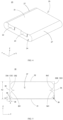
- FIG. 5 is a schematic structural view of a partition member 30 illustrated in FIG. 3 .
- the partition member 30 is substantially a rectangular frame.
- the partition member 30 is sleeved on the periphery of the electrode assembly 20, and is in interference fit with the electrode assembly 20.
- the partition member 30 is made of an elastic insulating material.
- the partition member 30 is made of polypropylene (PP).
- the partition member 30 includes a bottom plate 31, a top plate 32, and two side plates 33.
- the top plate 32 is positioned facing towards the bottom plate 31 in a height direction of the partition member 30 (Z-axis direction).
- the through-hole 34 is positioned closer to the bottom plate 31 than to the top plate 32.
- the two side plates 33 are positioned facing towards each other in a length direction of the partition member 30 (Y-axis direction), and are both connected between the top plate 32 and the bottom plate 31 to cooperatively define a through-recess 37.
- Ajoint between an inner wall surface of each of the two side plates 33 and an inner wall surface of the top plate 32 is an arc surface
- a joint between the inner wall surface of each of the two side plates 33 and an inner wall surface of the bottom plate 31 is an arc surface.
- inner wall surfaces at the four-corner joints of the partition member 30 are all arc surfaces, so as to be tightly attached to an outer peripheral surface of the electrode assembly 20.
- the two side plates 33 are respectively a first sub-side-plate 33A and a second sub-side-plate 33B.
- the partition member 30 defines a through-hole 34.
- the through-hole 34 is defined in the side plate 33, and penetrates through the side plate 33 in a thickness direction of the partition member 30 (X-axis direction).
- the through-hole 34 is a circular hole.
- a shape of the through-hole 34 may further be a rectangle, a triangle, a diamond, or the like, and the specific shape is not limited.
- a ratio of a height h1 of the through-hole 34 to a height h2 of the partition member 30 ranges from 0.05 to 0.1, and a ratio of a diameter d of the through-hole 34 to the height h2 of the partition member 30 ranges from 0.03 to 0.05.
- the height h1 of the through-hole 34 refers to a distance between a geometric center (i.e., a center of a circle in this embodiment) of the through-hole 34 and an outer wall surface of the bottom plate 31.
- the diameter d of the through-hole 34 refers to the diameter of the through-hole 34 when the through-hole 34 is a circular hole.
- the height h2 of the partition member 30 refers to a distance between an outer wall surface of the top plate 32 and the outer wall surface of the bottom plate 31.
- the through-hole 34 is implemented as two through-holes. Two through-holes 34 is positioned on the two side plates 33, respectively.
- the two through-holes 34 are positioned facing towards each other in the length direction of the partition member 30, so that the electrolyte can flow more evenly.
- the through-hole 34 includes two sets of through sub-holes. The two sets of through sub-holes are positioned on the two side plates 33, respectively, and the two sets of through sub-holes are positioned facing towards each other in the length direction of the partition member 30.
- the partition member 30 is further provided with a one-way valve 38.
- the one-way valve 38 may be disposed on a hole wall of the through-hole 34, and may also be disposed on a surface of the partition member 30 in the thickness direction. In the thickness direction of the partition member 30, an orthographic projection of the one-way valve 38 completely covers an orthographic projection of the through-hole 34.
- the one-way valve 38 is configured to make fluid flow in a single direction.
- the partition member 30 is further provided with a first protrusion 35 and a second protrusion 36.
- the first protrusion 35 and the second protrusion 36 are both positioned facing towards the through-recess 37. In the length direction of the partition member 30, the first protrusion 35 and the second protrusion 36 are positioned facing towards each other.
- the first protrusion 35 is positioned protruding from an inner wall surface of the first sub-side-plate 33A.
- the first protrusion 35 has a first contact surface 351 and a second contact surface 352 positioned facing away from the first contact surface 351, where both the first contact surface 351 and the second contact surface 352 are arc-shaped surfaces.
- first contact surface 351 is connected to the first sub-side-plate 33A, the other end of the first contact surface 351 is connected to one end of the second contact surface 352, and the other end of the second contact surface 352 is connected to the first sub-side-plate 33A.
- the first protrusion 35 is inserted into the first concave portion 26A.
- the first contact surface 351 and the second contact surface 352 are, respectively, attached to part of outer surfaces of two adjacent electrode assemblies 20 between which the first concave portion 26A is defined.
- the second protrusion 36 is positioned protruding from an inner wall surface of the second sub-side-plate 33B.
- the second protrusion 36 has a third contact surface 361 and a fourth contact surface 362 positioned facing away from the third contact surface 361, where both the third contact surface 361 and the fourth contact surface 362 are arc-shaped surfaces.
- One end of the third contact surface 361 is connected to the second sub-side-plate 33B, the other end of the third contact surface 361 is connected to one end of the fourth contact surface 362, and the other end of the fourth contact surface 362 is connected to the second sub-side-plate 33B.
- the second protrusion 36 is inserted into the second concave portion 26B.
- the third contact surface 361 and the fourth contact surface 362 are, respectively, attached to part of outer surfaces of two adjacent electrode assemblies 20 between which the second concave portion 26B is defined.
- one first protrusion 35 and one second protrusion 36 are provided, and the first protrusion 35 and the second protrusion 36 each are integrally formed with the partition member 30, so as to simplify a process and reduce processing cost.
- multiple first protrusions 35 and multiple second protrusions 36 may be provided, and the quantity of the first protrusions 35 may be the same as the quantity of the second protrusions 36.
- the multiple first protrusions 35 face towards the multiple second protrusions 36 in a one-to-one correspondence.
- the multiple first protrusions 35 are disposed at intervals and the multiple second protrusions 36 are disposed at intervals.
- Each first protrusion 35 is inserted into one first concave portion 26A, and each second protrusions 36 is inserted into one second concave portions 26B, so as to tightly abut against outer surfaces of the electrode assemblies 20, thereby achieving an interference fit between the partition member 30 and the electrode assembly 20.
- the first protrusion 35 and the second protrusion 36 each have a tip, that is, a joint between the first contact surface 351 and the second contact surface 352 is a sharp angle.
- the tip is inserted into the concave portion 26 and is configured to seal a gap between the electrode assemblies 20, when the partition member 30 is sleeved on the periphery of the electrode assembly 20, thereby achieving better sealing between the partition member 30 and the electrode assembly 20.
- FIG. 6 is a schematic structural view of a protection member 40 illustrated in FIG. 3 .
- the protection member 40 is substantially a rectangular hollow body and is made of an insulating material.
- the protection member 40 is sleeved on the outer surface of the electrode assembly 20, and is connected to the end cover assembly 10.
- the protection member 40 is configured to protect the electrode assembly 20 from being scratched by the housing 50 when the electrode assembly 20 is placed in the housing 50, and at the same time, is configured to insulate the electrode assembly 20 from the housing 50.
- the protection member 40 is mylar, i.e., a polyester film.
- the protection member 40 can be adhered through a hot-melt process to the end cover assembly 10 at one side of the end cover assembly 10 facing the electrode assembly 20.
- the protection member 40 defines a first accommodating cavity 41 and a first opening 42. In a length direction of the protection member 40 (X-axis direction), the first opening 42 is in communication with the first accommodating cavity 41.
- the first accommodating cavity 41 is configured to accommodate the electrode assembly 20 and the partition member 30. When the protection member 40 is sleeved on the electrode assembly 20, the electrode assembly 20 enters the first accommodating cavity 41 through the first opening 42.
- the protection member 40 has a bottom wall 43, a top wall 44, a first side wall 46, and two second side walls 45.
- the top wall 44 and the bottom wall 43 are positioned facing towards each other in a height direction of the protection member 40 (Z-axis direction).
- the two second side walls 45 are positioned facing towards each other in a width direction of the protection member 40 (Y-axis direction), and are both connected between the top wall 44 and the bottom wall 43.
- the first side wall 46 is positioned at one end of the protection member 40 in a length direction of the protection member 40 (X-axis direction), is connected between the top wall 44 and the bottom wall 43, and is connected between the two second side walls 45.
- the bottom wall 43, the top wall 44, the two second side walls 45, and the first side wall 46 are connected together to cooperatively define the first accommodating cavity 41.
- the first opening 42 is positioned at one end of the protection member 40 in the length direction of the protection member 40, and is positioned facing away from the first side wall 46.
- the two second side walls 45 are a first sub-side-wall 45A and a second sub-side-wall 45B.
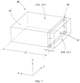
- FIG. 7 is a schematic structural view illustrating fixed connection between a partition member 30 and a protection member 40.
- the partition member 30 is fixedly connected in the first accommodating cavity 41 of the protection member 40.
- the bottom plate 31 is connected to and fixed to the bottom wall 43
- the top plate 32 is connected to and fixed to the top wall 44
- the first sub-side-plate 33A is connected to and fixed to the first sub-side-wall 45A
- the second sub-side-plate 33B is connected to and fixed to the second sub-side-wall 45B.
- the partition member 30 separates the first accommodating cavity 41 into a first accommodating sub-cavity 41A and a second accommodating sub-cavity 41B.
- a ratio of a distance L1 between the partition member 30 and the first side wall 46 to a length L2 of the protection member 40 ranges from 0.1 to 0.15.
- L1 refers to a distance between a surface of the partition member 30 facing the first side wall 46 and an outer wall surface of the first side wall 46.
- L2 refers to a dimension of the second side wall 45 in the length direction (X-axis direction).
- the volume of the first accommodating sub-cavity 41A is much greater than the volume of the second accommodating sub-cavity 41B.
- the partition member 30 may be adhered to the protection member 40, may also be fixedly connected to the protection member 40 through a hot-melt process, and may also be integrally formed with the protection member 40.
- FIG. 8 is a schematic structural view of a housing 50 illustrated in FIG. 3 .
- the housing 50 is substantially rectangular and is made of a metal material.
- the housing 50 defines a second accommodating cavity 51 and a second opening 52.
- the second opening 52 is in communication with the second accommodating cavity 51 in a length direction of the housing 50.
- the electrode assembly 20 and the protection member 40 are accommodated in the second accommodating cavity 51 through the second opening 52.
- the end cover assembly 10 is mounted in the second opening 52 and seals the housing 50.
- the energy-storage apparatus 100 further includes a holding plate 60.
- the holding plate 60 is configured to support the electrode assembly 20.
- the holding plate 60 is substantially in a rectangular sheet shape and is made of an insulating material.
- the holding plate 60 is accommodated in the second accommodating cavity 51 of the housing 50, is disposed between the first side wall 46 of the protection member 40 and the housing 50, and is fixedly connected to the first side wall 46.
- the holding plate 60 may be integrally formed with the protection member 40.
- FIG. 9 is a perspective structural view illustrating part of the energy-storage apparatus 100 illustrated in FIG. 2 .
- an electrolyte is injected into the protection member 40 through an electrolyte injection hole on the end cover assembly 10.
- the electrolyte is stored in the first accommodating cavity 41 and infiltrates the electrode assembly 20.
- the energy-storage apparatus 100 in an operating state is in a lying state, the first electrode assembly 20A and the second electrode assembly 20B are stacked in a direction perpendicular to the ground, and the second electrode assembly 20B is disposed away from the ground.
- the partition member 30 separates the first accommodating cavity 41 into the first accommodating sub-cavity 41A and the second accommodating sub-cavity 41B, and the volume of the first accommodating sub-cavity 41A is much greater than the volume of the second accommodating sub-cavity 41B, most of the electrode assembly 20 is located inside the first accommodating sub-cavity 41A, and a large amount of gas generated through reaction of the electrode assembly 20 with the electrolyte is also concentrated in the first accommodating sub-cavity 41A.
- a large amount of gas trapped in the first accommodating sub-cavity 41A will press the electrolyte, so as to facilitate the electrolyte to flow through the through-hole 34 on the partition member 30 from the first accommodating sub-cavity 41A to the second accommodating sub-cavity 41B, thereby raising the liquid level in the second accommodating sub-cavity 41B.
- a difference between the gas pressure in the first accommodating sub-cavity 41A and the gas pressure in the second accommodating sub-cavity 41B may increase gradually, and a difference between the liquid-level height of the electrolyte in the second accommodating sub-cavity 41B and the liquid-level height of the electrolyte in the first accommodating sub-cavity 41A may also increase gradually.
- the liquid level of the electrolyte in the first accommodating sub-cavity 41A is lower than the surface of the second electrode assembly 20B facing the ground, the liquid level of the electrolyte in the second accommodating sub-cavity 41B still continues to be higher than the surface of the second electrode assembly 20B facing the ground. Therefore, the electrolyte in the second accommodating sub-cavity 41B can continue to be in contact with the second end 25 of the second electrode assembly 20B, and is attracted by the separator of the second electrode assembly 20B through capillary action and transported to the entire second electrode assembly 20B. In this way, the electrolyte can circulate and simultaneously infiltrate multiple electrode assemblies 20.
- the first protrusion 35 and the second protrusion 36 of the partition member 30 each have a tip. After the electrode assembly 20 passes through the through-recess 37, the tip is inserted into the concave portion 26 and is configured to fill the gap between the electrode assemblies, thereby ensuring better sealing between the partition member 30 and the electrode assemblies 20.
- the gas generated in the first accommodating sub-cavity 41A can be prevented from flowing through the gap between the partition member 30 and the electrode assemblies 20 into the second accommodating sub-cavity 41B. Therefore, a difference between the gas pressure in the first accommodating sub-cavity 41A and the gas pressure in the second accommodating sub-cavity 41B cannot be reduced, and circulation and infiltration of the electrolyte into the multiple electrode assemblies 20 cannot be affected.
- one electrode assembly 20 is provided.
- the electrode assembly 20 When the energy-storage apparatus 100 is in a lying state, the electrode assembly 20 is disposed perpendicular to the ground.
- the electrolyte in the energy-storage apparatus 100 reacts with the electrode assembly 20 and is continuously consumed, and a liquid level of the electrolyte decreases continuously, a part of the electrode assembly 20 away from the ground is unable to be infiltrated with the electrolyte, which affects service life of the energy-storage apparatus 100.
- the partition member 30 is disposed to separate the first accommodating cavity 41 into the first accommodating sub-cavity 41A and the second accommodating sub-cavity 41B.
- the partition member 30 is further provided with a one-way valve 38, and in the thickness direction of the partition member 30, an orthographic projection of the one-way valve 38 completely covers an orthographic projection of the through-hole 34.
- the one-way valve 38 is configured so that the electrolyte can only flow from the first accommodating sub-cavity 41Ato the second accommodating sub-cavity 41B and cannot flow in an opposite direction, which is conducive to maintaining the difference between the liquid-level of the first accommodating sub-cavity 41A and the liquid-level of the second accommodating sub-cavity 41B. Therefore, the electrolyte can circulate and simultaneously infiltrate the multiple electrode assemblies 20.
- the partition member 30 is disposed to separate the first accommodating cavity 41 into the first accommodating sub-cavity 41A and the second accommodating sub-cavity 41B that have different sizes.
- the difference between the gas pressure in the first accommodating sub-cavity 41A and the gas pressure in the second accommodating sub-cavity 41B results in the difference between the liquid-level height of the electrolyte in the first accommodating sub-cavity 41A and the liquid-level height of the electrolyte in the second accommodating sub-cavity 41B.
- a relatively high liquid level can be maintained in the smaller second accommodating sub-cavity 41B, so as to realize continuous infiltration and replenishment for the second electrode assembly 20B. Therefore, even if the liquid level of the electrolyte decreases, infiltration of the electrolyte into the electrode assembly 20 away from the ground remains unaffected, which significantly improves service life of the energy-storage apparatus 100.
- the ratio of the height h1 of the through-hole 34 to the height h2 of the partition member 30 may be less than or equal to 0.1, so that the through-hole 34 may be not too high. This is because when the liquid level of the electrolyte decreases to the height of the through-hole 34, the gas will also flow through the through-hole 34. In this case, differences between the gas pressure in the first accommodating sub-cavity 41A and the gas pressure in the second accommodating sub-cavity 41B and between the liquid-level height of the electrolyte in the first accommodating sub-cavity 41A and the liquid-level height of the electrolyte in the second accommodating sub-cavity 41B cannot be maintained.
- the ratio of the height h1 of the through-hole 34 to the height h2 of the partition member 30 may be greater than or equal to 0.05, so that the through-hole 34 may be not too low and close to an edge of the partition member 30, thereby avoiding insufficient structural strength of the partition member 30 at the through-hole 34.
- the ratio of the diameter d of the through-hole 34 to the height h2 of the partition member 30 may be greater than or equal to 0.03, so that the through-hole 34 may be not too small to make the electrolyte flow between the first accommodating sub-cavity 41A and the second accommodating sub-cavity 41B.
- the ratio of the diameter d of the through-hole 34 to the height h2 of the partition member 30 may be less than or equal to 0.05, so that the through-hole 34 may be not too large and the structural strength of the partition member 30 at the through-hole 34 may be sufficient.
- the ratio of the distance L1 between the partition member 30 and the first side wall 46 to the length L2 of the protection member 40 may be greater than or equal to 0.1, so that the second accommodating sub-cavity 41B may be not too small in volume to store sufficient electrolyte to infiltrate the second electrode assembly 20B.
- the ratio of the distance L1 between the partition member 30 and the first side wall 46 to the length L2 of the protection member 40 may be less than or equal to 0.15, so that the second accommodating sub-cavity 41B may be not too large in volume and the first accommodating sub-cavity 41A may be not too small in volume, thereby forming sufficient differences between the gas pressure in the first accommodating sub-cavity 41A and the gas pressure in the second accommodating sub-cavity 41B and between the liquid-level height of the electrolyte in the first accommodating sub-cavity 41A and the liquid-level height of the electrolyte in the second accommodating sub-cavity 41B.
Landscapes
- Chemical & Material Sciences (AREA)
- Chemical Kinetics & Catalysis (AREA)
- Electrochemistry (AREA)
- General Chemical & Material Sciences (AREA)
- Engineering & Computer Science (AREA)
- Manufacturing & Machinery (AREA)
- Secondary Cells (AREA)
- Sealing Battery Cases Or Jackets (AREA)
Abstract
Description
- This disclosure relates to the field of energy-storage technology, and in particular, to an energy-storage apparatus, an energy-storage module, and an electricity-consumption device.
- Based on the design requirement of an energy-storage apparatus, some energy-storage apparatuses need to be laid flat while operating. When the energy-storage apparatus is laid flat, electrode assemblies inside the energy-storage apparatus are stacked. After an electrolyte in the energy-storage apparatus is consumed, a liquid level of the electrolyte may decrease. As a result, an electrode assembly located on an upper layer is unable to be infiltrated with the electrolyte, which affects usage performance of the energy-storage apparatus.
- In a first aspect, an energy-storage apparatus is provided in the disclosure. The energy-storage apparatus includes an end cover assembly, an electrode assembly, a partition member, a protection member, and a housing. The partition member defines a through-recess and a through-hole, both the through-recess and the through-hole penetrate through the partition member in a thickness direction of the partition member, and the through-recess and the through-hole are spaced apart from each other. The protection member defines a first accommodating cavity, and the first accommodating cavity defines a first opening. Both the partition member and the electrode assembly are accommodated in the first accommodating cavity. The electrode assembly passes through the through-recess, and the electrode assembly is in sealing connection to a recess wall of the through-recess. The partition member is in sealing connection to a cavity wall of the first accommodating cavity, and separates the first accommodating cavity into a first accommodating sub-cavity and a second accommodating sub-cavity. The first accommodating sub-cavity is in communication with the first opening, and the first accommodating sub-cavity is in communication with the second accommodating sub-cavity through the through-hole. The electrode assembly, the partition member, and the protection member are all accommodated in the housing. The end cover assembly is mounted at one end of the housing, and the end cover assembly seals the housing. The end cover assembly is opposite to the first opening and is connected to the protection member. An electrolyte of the energy-storage apparatus is accommodated in the housing and the first accommodating cavity. The through-hole is configured to make the electrolyte in the first accommodating sub-cavity flow to the second accommodating sub-cavity when a difference between the gas pressure in the first accommodating sub-cavity and the gas pressure in the second accommodating sub-cavity is generated during operation of the energy-storage apparatus.
- In a second aspect, an energy-storage module is provided in the disclosure. The energy-storage module includes multiple energy-storage apparatuses, where the multiple energy-storage apparatuses are electrically connected. Each energy-storage apparatus includes an end cover assembly, an electrode assembly, a partition member, a protection member, and a housing. The partition member defines a through-recess and a through-hole, both the through-recess and the through-hole penetrate through the partition member in a thickness direction of the partition member, and the through-recess and the through-hole are spaced apart from each other. The protection member defines a first accommodating cavity, and the first accommodating cavity defines a first opening. Both the partition member and the electrode assembly are accommodated in the first accommodating cavity. The electrode assembly passes through the through-recess, and the electrode assembly is in sealing connection to a recess wall of the through-recess. The partition member is in sealing connection to a cavity wall of the first accommodating cavity, and separates the first accommodating cavity into a first accommodating sub-cavity and a second accommodating sub-cavity. The first accommodating sub-cavity is in communication with the first opening, and the first accommodating sub-cavity is in communication with the second accommodating sub-cavity through the through-hole. The electrode assembly, the partition member, and the protection member are all accommodated in the housing. The end cover assembly is mounted at one end of the housing, and the end cover assembly seals the housing. The end cover assembly is opposite to the first opening and is connected to the protection member. An electrolyte of the energy-storage apparatus is accommodated in the housing and the first accommodating cavity. The through-hole is configured to make the electrolyte in the first accommodating sub-cavity flow to the second accommodating sub-cavity when a difference between the gas pressure in the first accommodating sub-cavity and the gas pressure in the second accommodating sub-cavity is generated during operation of the energy-storage apparatus.
- In a third aspect, an electricity-consumption device is provided in the disclosure. The electricity-consumption device includes an energy-storage module, where the energy-storage module is configured to supply power to the electricity-consumption device. The energy-storage module includes multiple energy-storage apparatuses, where the multiple energy-storage apparatuses are electrically connected. Each energy-storage apparatus includes an end cover assembly, an electrode assembly, a partition member, a protection member, and a housing. The partition member defines a through-recess and a through-hole, both the through-recess and the through-hole penetrate through the partition member in a thickness direction of the partition member, and the through-recess and the through-hole are spaced apart from each other. The protection member defines a first accommodating cavity, and the first accommodating cavity defines a first opening. Both the partition member and the electrode assembly are accommodated in the first accommodating cavity. The electrode assembly passes through the through-recess, and the electrode assembly is in sealing connection to a recess wall of the through-recess. The partition member is in sealing connection to a cavity wall of the first accommodating cavity, and separates the first accommodating cavity into a first accommodating sub-cavity and a second accommodating sub-cavity. The first accommodating sub-cavity is in communication with the first opening, and the first accommodating sub-cavity is in communication with the second accommodating sub-cavity through the through-hole. The electrode assembly, the partition member, and the protection member are all accommodated in the housing. The end cover assembly is mounted at one end of the housing, and the end cover assembly seals the housing. The end cover assembly is opposite to the first opening and is connected to the protection member. An electrolyte of the energy-storage apparatus is accommodated in the housing and the first accommodating cavity. The through-hole is configured to make the electrolyte in the first accommodating sub-cavity flow to the second accommodating sub-cavity when a difference between the gas pressure in the first accommodating sub-cavity and the gas pressure in the second accommodating sub-cavity is generated during operation of the energy-storage apparatus.
- As above mentioned, in embodiments of the disclosure, the partition member is disposed to separate the first accommodating cavity into the first accommodating sub-cavity and the second accommodating sub-cavity that have different sizes. A difference between the gas pressure in the first accommodating sub-cavity and the gas pressure in the second accommodating sub-cavity results in a difference between the liquid-level height of the electrolyte in the first accommodating sub-cavity and the liquid-level height of the electrolyte in the second accommodating sub-cavity. In this way, a relatively high liquid level can be maintained in the smaller second accommodating sub-cavity, so as to realize continuous infiltration and replenishment for the second electrode assembly. Therefore, even if the liquid level of the electrolyte decreases, infiltration of the electrolyte into the electrode assembly away from the bottom surface remains unaffected, which significantly improves service life of the energy-storage apparatus.
- In order to illustrate technical solutions in the disclosure more clearly, the following will give a brief introduction to the accompanying drawings required for describing implementations. Apparently, the accompanying drawings described below are merely some implementations of the disclosure. Based on these drawings, those of ordinary skilled in the art can also obtain other drawings without creative effort.
-
FIG. 1 is an application scenario view of a household energy-storage system provided in an embodiment of the disclosure. -
FIG. 2 is a schematic structural view of an energy-storage apparatus provided in an embodiment of the disclosure. -
FIG. 3 is an exploded structural view of the energy-storage apparatus illustrated inFIG. 2 . -
FIG. 4 is a schematic structural view of an electrode assembly illustrated inFIG. 3 . -
FIG. 5 is a schematic structural view of a partition member illustrated inFIG. 3 . -
FIG. 6 is a schematic structural view of a protection member illustrated inFIG. 3 . -
FIG. 7 is a schematic structural view illustrating fixed connection between a partition member and a protection member. -
FIG. 8 is a schematic structural view of a housing illustrated inFIG. 3 . -
FIG. 9 is a perspective structural view illustrating part of the energy-storage apparatus illustrated inFIG. 2 . -
FIG. 10 is a schematic block diagram of an energy-storage module. -
FIG. 11 is a schematic block diagram of an electricity-consumption device. - Reference signs: household energy-storage system 1000; energy-storage apparatus 100; electrical-energy conversion apparatus 200; customer load 300; end cover assembly 10; electrode assembly 20; partition member 30; protection member 40; housing 50; positive pole 11; negative pole 12; explosion-proof valve 13; main body 21; positive-electrode tab 22; negative-electrode tab 23; first end 24; second end 25; side portion 27; first electrode assembly 20A; second electrode assembly 20B; concave portion 26; first concave portion 26A; second concave portion 26B; bottom plate 31; top plate 32; side plate 33; through-recess 37; first sub-side-plate 33A; second sub-side-plate 33B; through-hole 34; first protrusion 35; first contact surface 351; second contact surface 352; second protrusion 36; third contact surface 361; fourth contact surface 362; first accommodating cavity 41; first opening 42; bottom wall 43; top wall 44; first side wall 46; second side wall 45; first sub-side-wall 45A; second sub-side-wall 45B; second accommodating cavity 51; second opening 52; holding plate 60; first accommodating sub-cavity 41A; second accommodating sub-cavity 41B; one-way valve 38; energy-storage module 500; electricity-consumption device 600.
- The following will describe technical solutions of embodiments of the disclosure clearly and completely with reference to the accompanying drawings in embodiments of the disclosure. Apparently, embodiments described herein are merely some embodiments, rather than all embodiments, of the disclosure. Based on the embodiments of the disclosure, all other embodiments obtained by those of ordinary skill in the art without creative effort shall fall within the protection scope of the disclosure.
- Since energy required by people has strong temporal and spatial characteristics, in order to use energy in a reasonable manner and improve energy utilization, a medium or a device is required to store energy in the same energy form or in another energy form converted and then to release energy in a specific energy form based on requirements of future applications. As is well-known, in order to achieve the big goal for carbon neutrality, the main way of generating green electrical energy is currently to develop green energy such as photovoltaics and wind power to replace fossil energy.
- At present, generation of green electrical energy is generally dependent on photovoltaics, wind power, water potential, and the like. However, in general, wind energy, solar energy, and the like are strongly intermittent and volatile, resulting in an unstable power grid, insufficient power supply at a power consumption peak, and overmuch power supply at a power consumption valley. In addition, an unstable voltage may further damage electric power. Therefore, "abandoned wind and abandoned light" may occur due to insufficient power demand or insufficient power-grid admitting ability, and energy storage is required to solve these problems. That is, electrical energy is stored by converting it into other forms of energy by physical or chemical means, and energy is released by converting it into electrical energy when needed. In brief, energy storage is similar to a large "power bank", which stores electrical energy when photovoltaics and wind energy are sufficient and releases stored electric power when needed.
-
FIG. 1 is an application scenario view of a household energy-storage system 1000 provided in an embodiment of the disclosure. - Taking a household energy-storage scenario for user-side energy storage as an example for illustration,
FIG. 1 illustrates a household energy-storage system. As illustrated inFIG. 1 , the household energy-storage system includes an energy-storage apparatus 100, an electrical-energy conversion apparatus 200 (for example, a photovoltaic panel), and a customer load 300 (for example, a road lamp, a household appliance, and the like). The energy-storage apparatus 100 is a small energy-storage container, and can be installed on an outdoor wall by means of hanging. In an embodiment, the electrical-energy conversion apparatus 200 can convert solar energy into electrical energy during a period of a valley electricity price and store the electrical energy with the energy-storage apparatus 100. Further, the electrical-energy conversion apparatus 200 can supply the electrical energy to thecustomer load 300 for use during a period of a peak electricity price, or supply the electrical energy to thecustomer load 300 for use during power outage/failure of a power grid. - In case where energy is stored by physical or electrochemical means as above described, taking electrochemical energy storage as an example, the energy-
storage apparatus 100 includes at least one group of chemical batteries. Chemical elements in the chemical batteries can be used as an energy-storage medium to implement a charging/discharging process through chemical reaction or change of the energy-storage medium. In brief, electrical energy generated by light energy and wind energy is stored in the at least one group of chemical batteries through chemical reaction or change of the energy-storage medium. When the usage of external electrical energy reaches a peak, the power stored in the at least one group of chemical batteries is released for use through chemical reaction or change of the energy-storage medium, or is transferred to a place where the power is scarce for reuse. -
FIG. 2 is a schematic structural view of an energy-storage apparatus 100 provided in an embodiment of the disclosure. - The disclosure provides an energy-
storage apparatus 100, an energy-storage module (illustrated inFIG. 10 ) including multiple energy-storage apparatuses 100, and an electricity-consumption device (illustrated inFIG. 11 ) with the energy-storage module. In this embodiment, for example, the energy-storage apparatus 100 is a battery. When the energy-storage apparatus 100 is a battery cell, the energy-storage apparatus 100 may be a square battery. The energy-storage module may include, but is not limited to, a battery module, a battery pack, a battery system, or the like. The electricity-consumption device may include, but is not limited to, a large-sized energy-storage container applied in a grid-side energy-storage scenario, a small and medium-sized energy-storage cabinet applied in a user-side industrial and commercial energy-storage scenario (a bank, a mall, and the like), and a small-sized household energy-storage container applied in a user-side household energy-storage scenario. - For ease of illustration, a length direction of the energy-
storage apparatus 100 illustrated inFIG. 2 is defined as an X-axis direction, a width direction of the energy-storage apparatus 100 is defined as a Y-axis direction, and a thickness direction of the energy-storage apparatus 100 is defined as a Z-axis direction, where every two of the X-axis direction, the Y-axis direction, and the Z-axis direction are perpendicular to each other. It may be noted that, "same" referred to in the disclosure means that some allowable error may exist. Directional terms such as "on", "under", "in", "out", and the like referred to in description of embodiments of the disclosure are described according to locations illustrated inFIG. 2 . A direction towards a positive direction of Z-axis is "on", a direction towards a negative direction of Z-axis is "under", a direction towards the inside of the energy-storage apparatus 100 is "in", and a direction towards the outside of the energy-storage apparatus 100 is "out", which do not constitute limitation to the energy-storage apparatus 100 in a practical application scenario. -
FIG. 3 is an exploded structural view of the energy-storage apparatus 100 illustrated inFIG. 2 . - As illustrated in
FIG. 3 , the energy-storage apparatus 100 includes anend cover assembly 10, anelectrode assembly 20, apartition member 30, aprotection member 40, and ahousing 50. One end of theelectrode assembly 20 is connected to theend cover assembly 10. Thepartition member 30 is fixedly connected in theprotection member 40, and theprotection member 40 and thepartition member 30 are both sleeved on a periphery of theelectrode assembly 20. Theelectrode assembly 20, thepartition member 30, and theprotection member 40 are all accommodated in thehousing 50. Theend cover assembly 10 is mounted at one end of thehousing 50 and seals thehousing 50. - As illustrated in
FIG. 2 , theend cover assembly 10 includes apositive pole 11, anegative pole 12, and an explosion-proof valve 13. In this embodiment, in a length direction of the end cover assembly 10 (Y-axis direction), thepositive pole 11 and thenegative pole 12 are located at two opposite ends of theend cover assembly 10 respectively and are spaced apart from each other. Both thepositive pole 11 and thenegative pole 12 are made of metal materials. Thepositive pole 11 serves as a positive terminal, when the energy-storage apparatus 100 is externally connected to another device. Thenegative pole 12 serves as a negative terminal, when the energy-storage apparatus 100 is externally connected to another device. The explosion-proof valve 13 is located between thepositive pole 11 and thenegative pole 12, and is spaced apart from thepositive pole 11 and thenegative pole 12. When the pressure inside the energy-storage apparatus 100 is too high, the explosion-proof valve 13 can automatically open to release the pressure, so as to prevent the energy-storage apparatus 100 from explosion. -
FIG. 4 is a schematic structural view of anelectrode assembly 20 illustrated inFIG. 3 . - The
electrode assembly 20 is substantially in a plate shape and is configured to store or release electrical energy through electrochemical reaction with an electrolyte. As illustrated inFIG. 4 , theelectrode assembly 20 includes amain body 21, a positive-electrode tab 22, and a negative-electrode tab 23. Theelectrode assembly 20 is formed by winding a positive electrode and a negative electrode, and a separator is generally disposed between the positive electrode and the negative electrode. Of the positive electrode and the negative electrode, portions having active materials constitute themain body 21 of theelectrode assembly 20. The remaining portion of the positive electrode constitutes the positive-electrode tab 22, and the remaining portion of the negative electrode constitutes the negative-electrode tab 23. Themain body 21 has afirst end 24, asecond end 25, and twoside portions 27. Thefirst end 24 and thesecond end 25 are positioned facing away from each other in a length direction of the main body 21 (X-axis direction). The twoside portions 27 are connected between thefirst end 24 and thesecond end 25, and the twoside portions 27 are positioned facing away from each other in a width direction of the main body 21 (Y-axis direction). In this embodiment, the two side portions are both in a semi-cylinder shape, and each of the two side portions protrudes in a direction away from the other side portion. In embodiments of the disclosure, the positive-electrode tab 22 and the negative-electrode tab 23 both are disposed at thefirst end 24 of themain body 21, and the positive-electrode tab 22 and the negative-electrode tab 23 are positioned facing towards and spaced apart from each other in the width direction of the main body 21 (Y-axis direction). In other embodiments, the positive-electrode tab 22 and the negative-electrode tab 23 can also be disposed at thefirst end 24 and thesecond end 25 of themain body 21, respectively. Theelectrode assembly 20 is connected to theend cover assembly 10. Thefirst end 24 is disposed facing towards theend cover assembly 10, and thesecond end 25 is disposed facing away from theend cover assembly 10. The positive-electrode tab 22 is welded with thepositive pole 11 and can be conductive with thepositive pole 11; and the negative-electrode tab 23 is welded with thenegative pole 12 and can be conductive with thenegative pole 12. - As illustrated in
FIG. 3 , in this embodiment, theelectrode assembly 20 is implemented as two electrode assemblies, and the twoelectrode assemblies 20 are respectively afirst electrode assembly 20A and asecond electrode assembly 20B. Thefirst electrode assembly 20A and thesecond electrode assembly 20B are stacked in a thickness direction of the electrode assembly 20 (Z-axis direction). Twoconcave portions 26 are defined between theside portions 27 of thefirst electrode assembly 20A and theside portions 27 of thesecond electrode assembly 20B, and the twoconcave portions 26 each extend in a length direction of the electrode assembly 20 (X-axis direction). The twoconcave portions 26 are respectively a firstconcave portion 26A and a secondconcave portion 26B, and the firstconcave portion 26A and the secondconcave portion 26B are positioned facing away from each other in a width direction of the electrode assembly 20 (Y-axis direction). An opening of the firstconcave portion 26A is positioned facing away from the secondconcave portion 26B, and an opening of the secondconcave portion 26B is positioned facing away from the firstconcave portion 26A. - In other embodiments, the
electrode assembly 20 may be implemented as one or more than two electrode assemblies, and the specific quantity is not limited. When theelectrode assembly 20 is implemented as more than two electrode assemblies,multiple electrode assemblies 20 are stacked in the thickness direction of theelectrode assembly 20. Themultiple electrode assemblies 20 define multiple firstconcave portions 26A and multiple secondconcave portions 26B. The multiple firstconcave portions 26A are positioned at intervals in the thickness direction of theelectrode assembly 20, and the multiple secondconcave portions 26B are positioned at intervals in the thickness direction of theelectrode assembly 20. Each of the multiple firstconcave portions 26A is positioned facing away from one of the multiple secondconcave portions 26B in the width direction of theelectrode assembly 20. -
FIG. 5 is a schematic structural view of apartition member 30 illustrated inFIG. 3 . - The
partition member 30 is substantially a rectangular frame. Thepartition member 30 is sleeved on the periphery of theelectrode assembly 20, and is in interference fit with theelectrode assembly 20. Thepartition member 30 is made of an elastic insulating material. In this embodiment, thepartition member 30 is made of polypropylene (PP). - As illustrated in
FIG. 5 , thepartition member 30 includes abottom plate 31, atop plate 32, and twoside plates 33. Thetop plate 32 is positioned facing towards thebottom plate 31 in a height direction of the partition member 30 (Z-axis direction). The through-hole 34 is positioned closer to thebottom plate 31 than to thetop plate 32. The twoside plates 33 are positioned facing towards each other in a length direction of the partition member 30 (Y-axis direction), and are both connected between thetop plate 32 and thebottom plate 31 to cooperatively define a through-recess 37. Ajoint between an inner wall surface of each of the twoside plates 33 and an inner wall surface of thetop plate 32 is an arc surface, and a joint between the inner wall surface of each of the twoside plates 33 and an inner wall surface of thebottom plate 31 is an arc surface. It may be understood that, inner wall surfaces at the four-corner joints of thepartition member 30 are all arc surfaces, so as to be tightly attached to an outer peripheral surface of theelectrode assembly 20. The twoside plates 33 are respectively a first sub-side-plate 33A and a second sub-side-plate 33B. - The
partition member 30 defines a through-hole 34. The through-hole 34 is defined in theside plate 33, and penetrates through theside plate 33 in a thickness direction of the partition member 30 (X-axis direction). In this embodiment, the through-hole 34 is a circular hole. In other embodiments, a shape of the through-hole 34 may further be a rectangle, a triangle, a diamond, or the like, and the specific shape is not limited. A ratio of a height h1 of the through-hole 34 to a height h2 of thepartition member 30 ranges from 0.05 to 0.1, and a ratio of a diameter d of the through-hole 34 to the height h2 of thepartition member 30 ranges from 0.03 to 0.05. The height h1 of the through-hole 34 refers to a distance between a geometric center (i.e., a center of a circle in this embodiment) of the through-hole 34 and an outer wall surface of thebottom plate 31. The diameter d of the through-hole 34 refers to the diameter of the through-hole 34 when the through-hole 34 is a circular hole. The height h2 of thepartition member 30 refers to a distance between an outer wall surface of thetop plate 32 and the outer wall surface of thebottom plate 31. In this embodiment, the through-hole 34 is implemented as two through-holes. Two through-holes 34 is positioned on the twoside plates 33, respectively. The two through-holes 34 are positioned facing towards each other in the length direction of thepartition member 30, so that the electrolyte can flow more evenly. In other embodiments, the through-hole 34 includes two sets of through sub-holes. The two sets of through sub-holes are positioned on the twoside plates 33, respectively, and the two sets of through sub-holes are positioned facing towards each other in the length direction of thepartition member 30. - In an embodiment, the
partition member 30 is further provided with a one-way valve 38. The one-way valve 38 may be disposed on a hole wall of the through-hole 34, and may also be disposed on a surface of thepartition member 30 in the thickness direction. In the thickness direction of thepartition member 30, an orthographic projection of the one-way valve 38 completely covers an orthographic projection of the through-hole 34. The one-way valve 38 is configured to make fluid flow in a single direction. - The
partition member 30 is further provided with afirst protrusion 35 and asecond protrusion 36. Thefirst protrusion 35 and thesecond protrusion 36 are both positioned facing towards the through-recess 37. In the length direction of thepartition member 30, thefirst protrusion 35 and thesecond protrusion 36 are positioned facing towards each other. Thefirst protrusion 35 is positioned protruding from an inner wall surface of the first sub-side-plate 33A. Thefirst protrusion 35 has afirst contact surface 351 and asecond contact surface 352 positioned facing away from thefirst contact surface 351, where both thefirst contact surface 351 and thesecond contact surface 352 are arc-shaped surfaces. One end of thefirst contact surface 351 is connected to the first sub-side-plate 33A, the other end of thefirst contact surface 351 is connected to one end of thesecond contact surface 352, and the other end of thesecond contact surface 352 is connected to the first sub-side-plate 33A. Thefirst protrusion 35 is inserted into the firstconcave portion 26A. Thefirst contact surface 351 and thesecond contact surface 352 are, respectively, attached to part of outer surfaces of twoadjacent electrode assemblies 20 between which the firstconcave portion 26A is defined. Thesecond protrusion 36 is positioned protruding from an inner wall surface of the second sub-side-plate 33B. Thesecond protrusion 36 has athird contact surface 361 and afourth contact surface 362 positioned facing away from thethird contact surface 361, where both thethird contact surface 361 and thefourth contact surface 362 are arc-shaped surfaces. One end of thethird contact surface 361 is connected to the second sub-side-plate 33B, the other end of thethird contact surface 361 is connected to one end of thefourth contact surface 362, and the other end of thefourth contact surface 362 is connected to the second sub-side-plate 33B. Thesecond protrusion 36 is inserted into the secondconcave portion 26B. Thethird contact surface 361 and thefourth contact surface 362 are, respectively, attached to part of outer surfaces of twoadjacent electrode assemblies 20 between which the secondconcave portion 26B is defined. - In this embodiment, one
first protrusion 35 and onesecond protrusion 36 are provided, and thefirst protrusion 35 and thesecond protrusion 36 each are integrally formed with thepartition member 30, so as to simplify a process and reduce processing cost. In other embodiments, multiplefirst protrusions 35 and multiplesecond protrusions 36 may be provided, and the quantity of thefirst protrusions 35 may be the same as the quantity of thesecond protrusions 36. In the length direction of thepartition member 30, the multiplefirst protrusions 35 face towards the multiplesecond protrusions 36 in a one-to-one correspondence. In the width direction of thepartition member 30, the multiplefirst protrusions 35 are disposed at intervals and the multiplesecond protrusions 36 are disposed at intervals. Eachfirst protrusion 35 is inserted into one firstconcave portion 26A, and eachsecond protrusions 36 is inserted into one secondconcave portions 26B, so as to tightly abut against outer surfaces of theelectrode assemblies 20, thereby achieving an interference fit between thepartition member 30 and theelectrode assembly 20. - In an embodiment, the
first protrusion 35 and thesecond protrusion 36 each have a tip, that is, a joint between thefirst contact surface 351 and thesecond contact surface 352 is a sharp angle. The tip is inserted into theconcave portion 26 and is configured to seal a gap between theelectrode assemblies 20, when thepartition member 30 is sleeved on the periphery of theelectrode assembly 20, thereby achieving better sealing between thepartition member 30 and theelectrode assembly 20. -
FIG. 6 is a schematic structural view of aprotection member 40 illustrated inFIG. 3 . - The
protection member 40 is substantially a rectangular hollow body and is made of an insulating material. Theprotection member 40 is sleeved on the outer surface of theelectrode assembly 20, and is connected to theend cover assembly 10. Theprotection member 40 is configured to protect theelectrode assembly 20 from being scratched by thehousing 50 when theelectrode assembly 20 is placed in thehousing 50, and at the same time, is configured to insulate theelectrode assembly 20 from thehousing 50. In this embodiment, theprotection member 40 is mylar, i.e., a polyester film. Theprotection member 40 can be adhered through a hot-melt process to theend cover assembly 10 at one side of theend cover assembly 10 facing theelectrode assembly 20. - The
protection member 40 defines a firstaccommodating cavity 41 and afirst opening 42. In a length direction of the protection member 40 (X-axis direction), thefirst opening 42 is in communication with the first accommodatingcavity 41. The firstaccommodating cavity 41 is configured to accommodate theelectrode assembly 20 and thepartition member 30. When theprotection member 40 is sleeved on theelectrode assembly 20, theelectrode assembly 20 enters the first accommodatingcavity 41 through thefirst opening 42. - As illustrated in
FIG. 6 , theprotection member 40 has abottom wall 43, atop wall 44, afirst side wall 46, and twosecond side walls 45. Thetop wall 44 and thebottom wall 43 are positioned facing towards each other in a height direction of the protection member 40 (Z-axis direction). The twosecond side walls 45 are positioned facing towards each other in a width direction of the protection member 40 (Y-axis direction), and are both connected between thetop wall 44 and thebottom wall 43. Thefirst side wall 46 is positioned at one end of theprotection member 40 in a length direction of the protection member 40 (X-axis direction), is connected between thetop wall 44 and thebottom wall 43, and is connected between the twosecond side walls 45. Thebottom wall 43, thetop wall 44, the twosecond side walls 45, and thefirst side wall 46 are connected together to cooperatively define the first accommodatingcavity 41. Thefirst opening 42 is positioned at one end of theprotection member 40 in the length direction of theprotection member 40, and is positioned facing away from thefirst side wall 46. The twosecond side walls 45 are a first sub-side-wall 45A and a second sub-side-wall 45B. -
FIG. 7 is a schematic structural view illustrating fixed connection between apartition member 30 and aprotection member 40. - As illustrated in
FIG. 5 to FIG. 7 , thepartition member 30 is fixedly connected in the first accommodatingcavity 41 of theprotection member 40. Thebottom plate 31 is connected to and fixed to thebottom wall 43, thetop plate 32 is connected to and fixed to thetop wall 44, the first sub-side-plate 33A is connected to and fixed to the first sub-side-wall 45A, and the second sub-side-plate 33B is connected to and fixed to the second sub-side-wall 45B. Thepartition member 30 separates the first accommodatingcavity 41 into a firstaccommodating sub-cavity 41A and a secondaccommodating sub-cavity 41B. In the length direction of theprotection member 40, thefirst opening 42, the first accommodatingsub-cavity 41A, and the second accommodating sub-cavity 41B are in communication, and the through-recess 37 is in communication with the first accommodatingsub-cavity 41A and the second accommodatingsub-cavity 41B. A ratio of a distance L1 between thepartition member 30 and thefirst side wall 46 to a length L2 of theprotection member 40 ranges from 0.1 to 0.15. L1 refers to a distance between a surface of thepartition member 30 facing thefirst side wall 46 and an outer wall surface of thefirst side wall 46. L2 refers to a dimension of thesecond side wall 45 in the length direction (X-axis direction). It may be understood that, the volume of the first accommodatingsub-cavity 41A is much greater than the volume of the second accommodatingsub-cavity 41B. Thepartition member 30 may be adhered to theprotection member 40, may also be fixedly connected to theprotection member 40 through a hot-melt process, and may also be integrally formed with theprotection member 40. -
FIG. 8 is a schematic structural view of ahousing 50 illustrated inFIG. 3 . - As illustrated in
FIG. 8 , thehousing 50 is substantially rectangular and is made of a metal material. Thehousing 50 defines a secondaccommodating cavity 51 and asecond opening 52. Thesecond opening 52 is in communication with the secondaccommodating cavity 51 in a length direction of thehousing 50. Theelectrode assembly 20 and theprotection member 40 are accommodated in the secondaccommodating cavity 51 through thesecond opening 52. Theend cover assembly 10 is mounted in thesecond opening 52 and seals thehousing 50. - As illustrated in
FIG. 3 , in this embodiment, the energy-storage apparatus 100 further includes a holdingplate 60. The holdingplate 60 is configured to support theelectrode assembly 20. The holdingplate 60 is substantially in a rectangular sheet shape and is made of an insulating material. The holdingplate 60 is accommodated in the secondaccommodating cavity 51 of thehousing 50, is disposed between thefirst side wall 46 of theprotection member 40 and thehousing 50, and is fixedly connected to thefirst side wall 46. In some embodiments, the holdingplate 60 may be integrally formed with theprotection member 40. -
FIG. 9 is a perspective structural view illustrating part of the energy-storage apparatus 100 illustrated inFIG. 2 . - After the energy-
storage apparatus 100 is assembled, an electrolyte is injected into theprotection member 40 through an electrolyte injection hole on theend cover assembly 10. The electrolyte is stored in the first accommodatingcavity 41 and infiltrates theelectrode assembly 20. In this embodiment, the energy-storage apparatus 100 in an operating state is in a lying state, thefirst electrode assembly 20A and thesecond electrode assembly 20B are stacked in a direction perpendicular to the ground, and thesecond electrode assembly 20B is disposed away from the ground. - In the operating state, as the electrolyte in the energy-
storage apparatus 100 reacts with theelectrode assembly 20 and is continuously consumed, a liquid level of the electrolyte also decreases continuously. In addition, when the electrolyte in the energy-storage apparatus 100 reacts with theelectrode assembly 20, gas can be generated. Since thepartition member 30 separates the first accommodatingcavity 41 into the first accommodatingsub-cavity 41A and the second accommodatingsub-cavity 41B, and the volume of the first accommodatingsub-cavity 41A is much greater than the volume of the second accommodatingsub-cavity 41B, most of theelectrode assembly 20 is located inside the first accommodatingsub-cavity 41A, and a large amount of gas generated through reaction of theelectrode assembly 20 with the electrolyte is also concentrated in the first accommodatingsub-cavity 41A. A large amount of gas trapped in the first accommodatingsub-cavity 41A will press the electrolyte, so as to facilitate the electrolyte to flow through the through-hole 34 on thepartition member 30 from the first accommodating sub-cavity 41A to the second accommodatingsub-cavity 41B, thereby raising the liquid level in the second accommodatingsub-cavity 41B. As the energy-storage apparatus 100 continues to operate and the electrolyte continues to be consumed to generate gas, a difference between the gas pressure in the first accommodatingsub-cavity 41A and the gas pressure in the second accommodatingsub-cavity 41B may increase gradually, and a difference between the liquid-level height of the electrolyte in the second accommodatingsub-cavity 41B and the liquid-level height of the electrolyte in the first accommodatingsub-cavity 41A may also increase gradually. Therefore, when the liquid level of the electrolyte in the first accommodatingsub-cavity 41A is lower than the surface of thesecond electrode assembly 20B facing the ground, the liquid level of the electrolyte in the second accommodatingsub-cavity 41B still continues to be higher than the surface of thesecond electrode assembly 20B facing the ground. Therefore, the electrolyte in the second accommodatingsub-cavity 41B can continue to be in contact with thesecond end 25 of thesecond electrode assembly 20B, and is attracted by the separator of thesecond electrode assembly 20B through capillary action and transported to the entiresecond electrode assembly 20B. In this way, the electrolyte can circulate and simultaneously infiltratemultiple electrode assemblies 20. - In this embodiment, since the
first protrusion 35 and thesecond protrusion 36 of thepartition member 30 each have a tip. After theelectrode assembly 20 passes through the through-recess 37, the tip is inserted into theconcave portion 26 and is configured to fill the gap between the electrode assemblies, thereby ensuring better sealing between thepartition member 30 and theelectrode assemblies 20. In this way, the gas generated in the first accommodatingsub-cavity 41A can be prevented from flowing through the gap between thepartition member 30 and theelectrode assemblies 20 into the second accommodatingsub-cavity 41B. Therefore, a difference between the gas pressure in the first accommodatingsub-cavity 41A and the gas pressure in the second accommodatingsub-cavity 41B cannot be reduced, and circulation and infiltration of the electrolyte into themultiple electrode assemblies 20 cannot be affected. - In an embodiment, one
electrode assembly 20 is provided. When the energy-storage apparatus 100 is in a lying state, theelectrode assembly 20 is disposed perpendicular to the ground. When the electrolyte in the energy-storage apparatus 100 reacts with theelectrode assembly 20 and is continuously consumed, and a liquid level of the electrolyte decreases continuously, a part of theelectrode assembly 20 away from the ground is unable to be infiltrated with the electrolyte, which affects service life of the energy-storage apparatus 100. Thepartition member 30 is disposed to separate the first accommodatingcavity 41 into the first accommodatingsub-cavity 41A and the second accommodatingsub-cavity 41B. In this way, a difference between the gas pressure in the first accommodatingsub-cavity 41A and the gas pressure in the second accommodatingsub-cavity 41B can be utilized to maintain a relatively high liquid level in the second accommodatingsub-cavity 41B, thereby continuously infiltrating and replenishing the part of theelectrode assembly 20 away from the ground. - In an embodiment, the
partition member 30 is further provided with a one-way valve 38, and in the thickness direction of thepartition member 30, an orthographic projection of the one-way valve 38 completely covers an orthographic projection of the through-hole 34. The one-way valve 38 is configured so that the electrolyte can only flow from the first accommodating sub-cavity 41Ato the second accommodatingsub-cavity 41B and cannot flow in an opposite direction, which is conducive to maintaining the difference between the liquid-level of the first accommodatingsub-cavity 41A and the liquid-level of the second accommodatingsub-cavity 41B. Therefore, the electrolyte can circulate and simultaneously infiltrate themultiple electrode assemblies 20. - As above mentioned, in embodiments of the disclosure, the
partition member 30 is disposed to separate the first accommodatingcavity 41 into the first accommodatingsub-cavity 41A and the second accommodatingsub-cavity 41B that have different sizes. The difference between the gas pressure in the first accommodatingsub-cavity 41A and the gas pressure in the second accommodating sub-cavity 41B results in the difference between the liquid-level height of the electrolyte in the first accommodatingsub-cavity 41A and the liquid-level height of the electrolyte in the second accommodatingsub-cavity 41B. In this way, a relatively high liquid level can be maintained in the smaller second accommodatingsub-cavity 41B, so as to realize continuous infiltration and replenishment for thesecond electrode assembly 20B. Therefore, even if the liquid level of the electrolyte decreases, infiltration of the electrolyte into theelectrode assembly 20 away from the ground remains unaffected, which significantly improves service life of the energy-storage apparatus 100. - As illustrated in
FIG. 5 , in embodiments of the disclosure, the ratio of the height h1 of the through-hole 34 to the height h2 of thepartition member 30 may be less than or equal to 0.1, so that the through-hole 34 may be not too high. This is because when the liquid level of the electrolyte decreases to the height of the through-hole 34, the gas will also flow through the through-hole 34. In this case, differences between the gas pressure in the first accommodatingsub-cavity 41A and the gas pressure in the second accommodatingsub-cavity 41B and between the liquid-level height of the electrolyte in the first accommodatingsub-cavity 41A and the liquid-level height of the electrolyte in the second accommodatingsub-cavity 41B cannot be maintained. Therefore, thesecond electrode assembly 20B cannot be continuously infiltrated. The ratio of the height h1 of the through-hole 34 to the height h2 of thepartition member 30 may be greater than or equal to 0.05, so that the through-hole 34 may be not too low and close to an edge of thepartition member 30, thereby avoiding insufficient structural strength of thepartition member 30 at the through-hole 34. - In embodiments of the disclosure, the ratio of the diameter d of the through-
hole 34 to the height h2 of thepartition member 30 may be greater than or equal to 0.03, so that the through-hole 34 may be not too small to make the electrolyte flow between the first accommodatingsub-cavity 41A and the second accommodatingsub-cavity 41B. The ratio of the diameter d of the through-hole 34 to the height h2 of thepartition member 30 may be less than or equal to 0.05, so that the through-hole 34 may be not too large and the structural strength of thepartition member 30 at the through-hole 34 may be sufficient. - As illustrated in
FIG. 7 , in embodiments of the disclosure, the ratio of the distance L1 between thepartition member 30 and thefirst side wall 46 to the length L2 of theprotection member 40 may be greater than or equal to 0.1, so that the second accommodatingsub-cavity 41B may be not too small in volume to store sufficient electrolyte to infiltrate thesecond electrode assembly 20B. The ratio of the distance L1 between thepartition member 30 and thefirst side wall 46 to the length L2 of theprotection member 40 may be less than or equal to 0.15, so that the second accommodatingsub-cavity 41B may be not too large in volume and the first accommodatingsub-cavity 41A may be not too small in volume, thereby forming sufficient differences between the gas pressure in the first accommodatingsub-cavity 41A and the gas pressure in the second accommodatingsub-cavity 41B and between the liquid-level height of the electrolyte in the first accommodatingsub-cavity 41A and the liquid-level height of the electrolyte in the second accommodatingsub-cavity 41B. - Embodiments of the disclosure are described in detail in the above. Principles and implementation manners of the disclosure are elaborated with specific embodiments herein. The illustration of embodiments above is only used to help understanding of methods and core ideas of the disclosure. Additionally, for those of ordinary skill in the art, according to ideas of the disclosure, there will be changes in the specific implementation manners and application scopes. In summary, contents of this specification may not be understood as limitation on the disclosure.
Claims (11)
- An energy-storage apparatus (100), comprising an end cover assembly (10), an electrode assembly (20), a partition member (30), a protection member (40), and a housing (50), whereinthe partition member (30) defines a through-recess (37) and a through-hole (34), both the through-recess (37) and the through-hole (34) penetrate through the partition member (30) in a thickness direction of the partition member (30), and the through-recess (37) and the through-hole (34) are spaced apart from each other;the protection member (40) defines a first accommodating cavity (41), the first accommodating cavity (41) defines a first opening (42), both the partition member (30) and the electrode assembly (20) are accommodated in the first accommodating cavity (41), the electrode assembly (20) passes through the through-recess (37), and the electrode assembly (20) is in sealing connection to a recess wall of the through-recess (37); the partition member (30) is in sealing connection to a cavity wall of the first accommodating cavity (41) and separates the first accommodating cavity (41) into a first accommodating sub-cavity (41A) and a second accommodating sub-cavity (41B), the first accommodating sub-cavity (41A) is in communication with the first opening (42), and the first accommodating sub-cavity (41A) is in communication with the second accommodating sub-cavity (41B) through the through-hole (34);the housing (50) defines a second opening (52), the protection member (40) is accommodated in the housing (50) through the second opening (52), the end cover assembly (10) is mounted in the second opening (52) and seals the second opening (52), the end cover assembly (10) is opposite to the first opening (42) and the end cover assembly (10) is connected to the protection member (40), and an electrolyte of the energy-storage apparatus (100) is accommodated in the housing (50) and the first accommodating cavity (41); andthe through-hole is configured to make the electrolyte in the first accommodating sub-cavity (41A) flow to the second accommodating sub-cavity (41B) when a difference between a gas pressure in the first accommodating sub-cavity (41A) and a gas pressure in the second accommodating sub-cavity (41B) is generated during operation of the energy-storage apparatus (100).
- The energy-storage apparatus (100) of claim 1, wherein the partition member (30) comprises a bottom plate (31), a top plate (32), and two side plates (33), the top plate (32) is positioned facing towards the bottom plate (31) in a height direction of the partition member (30), the two side plates (33) are positioned facing towards each other in a length direction of the partition member (30), and the through-hole (34) is positioned closer to the bottom plate (31) than to the top plate (32); a distance between a geometric center of the through-hole (34) and an outer wall surface of the bottom plate (31) is h1, and a distance between an outer wall surface of the top plate (32) and the outer wall surface of the bottom plate (31) is h2; and a ratio of h1 to h2 ranges from 0.05 to 0.1.
- The energy-storage apparatus (100) of claim 1, wherein the protection member (40) has a first side wall (46), the first side wall (46) is disposed at one end of the protection member (40) away from the end cover assembly (10), and a ratio of a distance between the partition member (30) and the first side wall (46) to a dimension of the protection member (40) in a length direction of the partition member (30) ranges from 0.1 to 0.15.
- The energy-storage apparatus (100) of claim 1, wherein the partition member (30) comprises a bottom plate (31), a top plate (32), and two side plates (33), the top plate (32) is positioned facing towards the bottom plate (31) in a height direction of the partition member (30), the two side plates (33) are positioned facing towards each other in a length direction of the partition member (30), and the through-hole (34) is positioned closer to the bottom plate (31) than to the top plate (32); and the through-hole (34) is a circular hole, and a ratio of a diameter of the through-hole (34) to a distance between an outer wall surface of the top plate (32) and the outer wall surface of the bottom plate (31) ranges from 0.03 to 0.05.
- The energy-storage apparatus (100) of claim 1, wherein the partition member (30) comprises two side plates (33), the two side plates (33) are positioned facing towards each other in a length direction of the partition member (30), the through-hole (34) comprises two sets of through sub-holes, each of the two sets of through sub-holes penetrates through one of the two side plates (33), and the two sets of through sub-holes are positioned facing towards each other in the length direction of the partition member (30).
- The energy-storage apparatus (100) of any one of claims 1 to 4, wherein the partition member (30) comprises two side plates (33), and the two side plates (33) are positioned facing towards each other in a length direction of the partition member (30); the partition member (30) is provided with a first protrusion (35) and a second protrusion (36), the first protrusion (35) and the second protrusion (36) are positioned protruding from the two side plates (33) respectively and towards the through-recess (37), and in the length direction of the partition member (30), the first protrusion (35) and the second protrusion (36) are positioned facing towards each other;the electrode assembly (20) is implemented as two electrode assemblies, the two electrode assemblies (20) are stacked in a thickness direction of the electrode assembly (20), a first concave portion (26A) and a second concave portion (26B) are defined between the two electrode assemblies (20), and the first concave portion (26A) and the second concave portion (26B) are positioned facing away from each other in a width direction of the electrode assembly (20);the first protrusion (35) is inserted into the first concave portion (26A) and is configured to seal a gap between the two electrode assemblies (20), and surfaces of the first protrusion (35) abuts against part of outer surfaces of the two electrode assemblies (20) between which the first concave portion (26A) is defined; andthe second protrusion (36) is inserted into the second concave portion (26B) and is configured to seal the gap between the two electrode assemblies (20), and surfaces of the second protrusion (36) abuts against part of outer surfaces of the two electrode assemblies (20) between which the second concave portion (26B) is defined.
- The energy-storage apparatus (100) of claim 6, wherein the first protrusion (35) and the second protrusion (36) are integrally formed with the two side plates (33) respectively.
- The energy-storage apparatus (100) of any one of claims 1 to 4, wherein the partition member (30) and the protection member (40) are integrally formed.
- The energy-storage apparatus (100) of claim 1, wherein the partition member (30) is further provided with a one-way valve, and in the thickness direction of the partition member (30), an orthographic projection of the one-way valve completely covers an orthographic projection of the through-hole (34); the one-way valve is configured to only allow fluid to flow from the first accommodating sub-cavity (41A) to the second accommodating sub-cavity (41B).
- An energy-storage module, comprising a plurality of energy-storage apparatuses (100) of any one of claims 1 to 9, the plurality of energy-storage apparatuses (100) being electrically connected.
- A electricity-consumption device, comprising the energy-storage module of claim 10, the energy-storage module being configured to supply power to the power-consuming device.
Applications Claiming Priority (1)
| Application Number | Priority Date | Filing Date | Title |
|---|---|---|---|
| CN202310791439.XA CN116706439A (en) | 2023-06-29 | 2023-06-29 | Energy storage device, energy storage module and electrical equipment |
Publications (2)
| Publication Number | Publication Date |
|---|---|
| EP4485632A1 true EP4485632A1 (en) | 2025-01-01 |
| EP4485632B1 EP4485632B1 (en) | 2025-12-17 |
Family
ID=87837347
Family Applications (1)
| Application Number | Title | Priority Date | Filing Date |
|---|---|---|---|
| EP24168503.1A Active EP4485632B1 (en) | 2023-06-29 | 2024-04-04 | Energy-storage apparatus, energy-storage module, and electricity-consumption device |
Country Status (5)
| Country | Link |
|---|---|
| US (1) | US20250007135A1 (en) |
| EP (1) | EP4485632B1 (en) |
| CN (1) | CN116706439A (en) |
| ES (1) | ES3063925T3 (en) |
| WO (1) | WO2025001166A1 (en) |
Families Citing this family (1)
| Publication number | Priority date | Publication date | Assignee | Title |
|---|---|---|---|---|
| CN116706439A (en) * | 2023-06-29 | 2023-09-05 | 厦门海辰储能科技股份有限公司 | Energy storage device, energy storage module and electrical equipment |
Citations (1)
| Publication number | Priority date | Publication date | Assignee | Title |
|---|---|---|---|---|
| US20170331090A1 (en) * | 2016-05-16 | 2017-11-16 | Contemporary Amperex Technology Co., Limited | Secondary Battery |
Family Cites Families (5)
| Publication number | Priority date | Publication date | Assignee | Title |
|---|---|---|---|---|
| JP2011054539A (en) * | 2009-09-04 | 2011-03-17 | Toyota Motor Corp | Method of manufacturing battery |
| JP2015232941A (en) * | 2014-06-09 | 2015-12-24 | 株式会社Gsユアサ | Power storage device, and method for manufacturing power storage device |
| CN112542605A (en) * | 2020-12-24 | 2021-03-23 | 深圳新源柔性科技有限公司 | Flexible reserve battery |
| CN114824681B (en) * | 2022-06-27 | 2022-09-09 | 宁德新能源科技有限公司 | Electrochemical devices and electronic devices |
| CN116706439A (en) * | 2023-06-29 | 2023-09-05 | 厦门海辰储能科技股份有限公司 | Energy storage device, energy storage module and electrical equipment |
-
2023
- 2023-06-29 CN CN202310791439.XA patent/CN116706439A/en active Pending
-
2024
- 2024-02-06 WO PCT/CN2024/076292 patent/WO2025001166A1/en not_active Ceased
- 2024-04-03 US US18/626,078 patent/US20250007135A1/en active Pending
- 2024-04-04 EP EP24168503.1A patent/EP4485632B1/en active Active
- 2024-04-04 ES ES24168503T patent/ES3063925T3/en active Active
Patent Citations (1)
| Publication number | Priority date | Publication date | Assignee | Title |
|---|---|---|---|---|
| US20170331090A1 (en) * | 2016-05-16 | 2017-11-16 | Contemporary Amperex Technology Co., Limited | Secondary Battery |
Also Published As
| Publication number | Publication date |
|---|---|
| WO2025001166A1 (en) | 2025-01-02 |
| US20250007135A1 (en) | 2025-01-02 |
| EP4485632B1 (en) | 2025-12-17 |
| ES3063925T3 (en) | 2026-04-21 |
| CN116706439A (en) | 2023-09-05 |
Similar Documents
| Publication | Publication Date | Title |
|---|---|---|
| CN116470240B (en) | End cover assembly, energy storage device and electric equipment | |
| CN116207432B (en) | End cover assembly, energy storage device and electrical equipment | |
| CN116544627B (en) | End cover unit, energy storage device and electrical equipment | |
| CN117059979B (en) | End cover assembly, energy storage device and electric equipment | |
| CN116345029A (en) | End cover assembly, energy storage device and electric equipment | |
| EP4485632A1 (en) | Energy-storage apparatus, energy-storage module, and electricity-consumption device | |
| CN116914327B (en) | Liquid cooling modules, energy storage devices and energy storage systems | |
| CN116742226B (en) | End cover assembly, energy storage device and electric equipment | |
| CN222953222U (en) | End cover assembly, energy storage device and electrical equipment | |
| CN116344834B (en) | Energy storage device and electric equipment | |
| CN116315481A (en) | Energy storage device and electric equipment | |
| CN116154426A (en) | End cover assembly, energy storage device and electric equipment | |
| CN116565477A (en) | End cover assembly, energy storage device and electric equipment | |
| EP4485641B1 (en) | Energy-storage device and electricity-consumption apparatus | |
| CN116565413B (en) | Energy storage devices and electrical equipment | |
| CN223309003U (en) | Current collecting disc, energy storage device and electric equipment | |
| CN222883679U (en) | End cover assembly, energy storage device and electric equipment | |
| CN222851534U (en) | End cover assembly, energy storage device and electrical equipment | |
| CN118263635B (en) | Sealing device, energy storage device and electric equipment | |
| CN222867749U (en) | Energy storage devices and electrical equipment | |
| CN222233746U (en) | Energy storage devices and electrical equipment | |
| CN223218361U (en) | Energy storage device and electric equipment | |
| CN223911674U (en) | Energy storage device and electric equipment | |
| CN116632426A (en) | End cap assembly, energy storage device and electrical equipment | |
| CN120073235A (en) | Energy storage device and electric equipment |
Legal Events
| Date | Code | Title | Description |
|---|---|---|---|
| PUAI | Public reference made under article 153(3) epc to a published international application that has entered the european phase |
Free format text: ORIGINAL CODE: 0009012 |
|
| STAA | Information on the status of an ep patent application or granted ep patent |
Free format text: STATUS: THE APPLICATION HAS BEEN PUBLISHED |
|
| AK | Designated contracting states |
Kind code of ref document: A1 Designated state(s): AL AT BE BG CH CY CZ DE DK EE ES FI FR GB GR HR HU IE IS IT LI LT LU LV MC ME MK MT NL NO PL PT RO RS SE SI SK SM TR |
|
| RAP1 | Party data changed (applicant data changed or rights of an application transferred) |
Owner name: HITHIUM TECH HK LIMITED |
|
| STAA | Information on the status of an ep patent application or granted ep patent |
Free format text: STATUS: REQUEST FOR EXAMINATION WAS MADE |
|
| 17P | Request for examination filed |
Effective date: 20250415 |
|
| GRAP | Despatch of communication of intention to grant a patent |
Free format text: ORIGINAL CODE: EPIDOSNIGR1 |
|
| STAA | Information on the status of an ep patent application or granted ep patent |
Free format text: STATUS: GRANT OF PATENT IS INTENDED |
|
| INTG | Intention to grant announced |
Effective date: 20250915 |
|
| GRAS | Grant fee paid |
Free format text: ORIGINAL CODE: EPIDOSNIGR3 |
|
| GRAA | (expected) grant |
Free format text: ORIGINAL CODE: 0009210 |
|
| STAA | Information on the status of an ep patent application or granted ep patent |
Free format text: STATUS: THE PATENT HAS BEEN GRANTED |
|
| AK | Designated contracting states |
Kind code of ref document: B1 Designated state(s): AL AT BE BG CH CY CZ DE DK EE ES FI FR GB GR HR HU IE IS IT LI LT LU LV MC ME MK MT NL NO PL PT RO RS SE SI SK SM TR |
|
| REG | Reference to a national code |
Ref country code: CH Ref legal event code: F10 Free format text: ST27 STATUS EVENT CODE: U-0-0-F10-F00 (AS PROVIDED BY THE NATIONAL OFFICE) Effective date: 20251217 Ref country code: GB Ref legal event code: FG4D |
|
| REG | Reference to a national code |
Ref country code: DE Ref legal event code: R096 Ref document number: 602024001694 Country of ref document: DE |
|
| REG | Reference to a national code |
Ref country code: NL Ref legal event code: FP |
|
| REG | Reference to a national code |
Ref country code: LT Ref legal event code: MG9D |
|
| PG25 | Lapsed in a contracting state [announced via postgrant information from national office to epo] |
Ref country code: NO Free format text: LAPSE BECAUSE OF FAILURE TO SUBMIT A TRANSLATION OF THE DESCRIPTION OR TO PAY THE FEE WITHIN THE PRESCRIBED TIME-LIMIT Effective date: 20260317 |
|
| PG25 | Lapsed in a contracting state [announced via postgrant information from national office to epo] |
Ref country code: FI Free format text: LAPSE BECAUSE OF FAILURE TO SUBMIT A TRANSLATION OF THE DESCRIPTION OR TO PAY THE FEE WITHIN THE PRESCRIBED TIME-LIMIT Effective date: 20251217 Ref country code: HR Free format text: LAPSE BECAUSE OF FAILURE TO SUBMIT A TRANSLATION OF THE DESCRIPTION OR TO PAY THE FEE WITHIN THE PRESCRIBED TIME-LIMIT Effective date: 20251217 |
|
| PG25 | Lapsed in a contracting state [announced via postgrant information from national office to epo] |
Ref country code: RS Free format text: LAPSE BECAUSE OF FAILURE TO SUBMIT A TRANSLATION OF THE DESCRIPTION OR TO PAY THE FEE WITHIN THE PRESCRIBED TIME-LIMIT Effective date: 20260317 |
|
| REG | Reference to a national code |
Ref country code: ES Ref legal event code: FG2A Ref document number: 3063925 Country of ref document: ES Kind code of ref document: T3 Effective date: 20260421 |
|
| PG25 | Lapsed in a contracting state [announced via postgrant information from national office to epo] |
Ref country code: LV Free format text: LAPSE BECAUSE OF FAILURE TO SUBMIT A TRANSLATION OF THE DESCRIPTION OR TO PAY THE FEE WITHIN THE PRESCRIBED TIME-LIMIT Effective date: 20251217 |