EP4485621A1 - Energy storage device - Google Patents
Energy storage device Download PDFInfo
- Publication number
- EP4485621A1 EP4485621A1 EP24174551.2A EP24174551A EP4485621A1 EP 4485621 A1 EP4485621 A1 EP 4485621A1 EP 24174551 A EP24174551 A EP 24174551A EP 4485621 A1 EP4485621 A1 EP 4485621A1
- Authority
- EP
- European Patent Office
- Prior art keywords
- electrical
- liquid cooling
- connector
- energy storage
- storage device
- Prior art date
- Legal status (The legal status is an assumption and is not a legal conclusion. Google has not performed a legal analysis and makes no representation as to the accuracy of the status listed.)
- Granted
Links
Images



Classifications
-
- H—ELECTRICITY
- H01—ELECTRIC ELEMENTS
- H01M—PROCESSES OR MEANS, e.g. BATTERIES, FOR THE DIRECT CONVERSION OF CHEMICAL ENERGY INTO ELECTRICAL ENERGY
- H01M50/00—Constructional details or processes of manufacture of the non-active parts of electrochemical cells other than fuel cells, e.g. hybrid cells
- H01M50/20—Mountings; Secondary casings or frames; Racks, modules or packs; Suspension devices; Shock absorbers; Transport or carrying devices; Holders
- H01M50/233—Mountings; Secondary casings or frames; Racks, modules or packs; Suspension devices; Shock absorbers; Transport or carrying devices; Holders characterised by physical properties of casings or racks, e.g. dimensions
- H01M50/24—Mountings; Secondary casings or frames; Racks, modules or packs; Suspension devices; Shock absorbers; Transport or carrying devices; Holders characterised by physical properties of casings or racks, e.g. dimensions adapted for protecting batteries from their environment, e.g. from corrosion
-
- H—ELECTRICITY
- H01—ELECTRIC ELEMENTS
- H01M—PROCESSES OR MEANS, e.g. BATTERIES, FOR THE DIRECT CONVERSION OF CHEMICAL ENERGY INTO ELECTRICAL ENERGY
- H01M10/00—Secondary cells; Manufacture thereof
- H01M10/42—Methods or arrangements for servicing or maintenance of secondary cells or secondary half-cells
- H01M10/425—Structural combination with electronic components, e.g. electronic circuits integrated to the outside of the casing
- H01M10/4257—Smart batteries, e.g. electronic circuits inside the housing of the cells or batteries
-
- H—ELECTRICITY
- H01—ELECTRIC ELEMENTS
- H01M—PROCESSES OR MEANS, e.g. BATTERIES, FOR THE DIRECT CONVERSION OF CHEMICAL ENERGY INTO ELECTRICAL ENERGY
- H01M10/00—Secondary cells; Manufacture thereof
- H01M10/60—Heating or cooling; Temperature control
- H01M10/61—Types of temperature control
- H01M10/613—Cooling or keeping cold
-
- H—ELECTRICITY
- H01—ELECTRIC ELEMENTS
- H01M—PROCESSES OR MEANS, e.g. BATTERIES, FOR THE DIRECT CONVERSION OF CHEMICAL ENERGY INTO ELECTRICAL ENERGY
- H01M10/00—Secondary cells; Manufacture thereof
- H01M10/60—Heating or cooling; Temperature control
- H01M10/65—Means for temperature control structurally associated with the cells
- H01M10/655—Solid structures for heat exchange or heat conduction
- H01M10/6554—Rods or plates
-
- H—ELECTRICITY
- H01—ELECTRIC ELEMENTS
- H01M—PROCESSES OR MEANS, e.g. BATTERIES, FOR THE DIRECT CONVERSION OF CHEMICAL ENERGY INTO ELECTRICAL ENERGY
- H01M10/00—Secondary cells; Manufacture thereof
- H01M10/60—Heating or cooling; Temperature control
- H01M10/65—Means for temperature control structurally associated with the cells
- H01M10/655—Solid structures for heat exchange or heat conduction
- H01M10/6556—Solid parts with flow channel passages or pipes for heat exchange
-
- H—ELECTRICITY
- H01—ELECTRIC ELEMENTS
- H01M—PROCESSES OR MEANS, e.g. BATTERIES, FOR THE DIRECT CONVERSION OF CHEMICAL ENERGY INTO ELECTRICAL ENERGY
- H01M10/00—Secondary cells; Manufacture thereof
- H01M10/60—Heating or cooling; Temperature control
- H01M10/65—Means for temperature control structurally associated with the cells
- H01M10/656—Means for temperature control structurally associated with the cells characterised by the type of heat-exchange fluid
- H01M10/6567—Liquids
-
- H—ELECTRICITY
- H01—ELECTRIC ELEMENTS
- H01M—PROCESSES OR MEANS, e.g. BATTERIES, FOR THE DIRECT CONVERSION OF CHEMICAL ENERGY INTO ELECTRICAL ENERGY
- H01M10/00—Secondary cells; Manufacture thereof
- H01M10/60—Heating or cooling; Temperature control
- H01M10/65—Means for temperature control structurally associated with the cells
- H01M10/656—Means for temperature control structurally associated with the cells characterised by the type of heat-exchange fluid
- H01M10/6567—Liquids
- H01M10/6568—Liquids characterised by flow circuits, e.g. loops, located externally to the cells or cell casings
-
- H—ELECTRICITY
- H01—ELECTRIC ELEMENTS
- H01M—PROCESSES OR MEANS, e.g. BATTERIES, FOR THE DIRECT CONVERSION OF CHEMICAL ENERGY INTO ELECTRICAL ENERGY
- H01M50/00—Constructional details or processes of manufacture of the non-active parts of electrochemical cells other than fuel cells, e.g. hybrid cells
- H01M50/20—Mountings; Secondary casings or frames; Racks, modules or packs; Suspension devices; Shock absorbers; Transport or carrying devices; Holders
- H01M50/204—Racks, modules or packs for multiple batteries or multiple cells
- H01M50/207—Racks, modules or packs for multiple batteries or multiple cells characterised by their shape
- H01M50/209—Racks, modules or packs for multiple batteries or multiple cells characterised by their shape adapted for prismatic or rectangular cells
-
- H—ELECTRICITY
- H01—ELECTRIC ELEMENTS
- H01M—PROCESSES OR MEANS, e.g. BATTERIES, FOR THE DIRECT CONVERSION OF CHEMICAL ENERGY INTO ELECTRICAL ENERGY
- H01M50/00—Constructional details or processes of manufacture of the non-active parts of electrochemical cells other than fuel cells, e.g. hybrid cells
- H01M50/20—Mountings; Secondary casings or frames; Racks, modules or packs; Suspension devices; Shock absorbers; Transport or carrying devices; Holders
- H01M50/244—Secondary casings; Racks; Suspension devices; Carrying devices; Holders characterised by their mounting method
-
- H—ELECTRICITY
- H01—ELECTRIC ELEMENTS
- H01M—PROCESSES OR MEANS, e.g. BATTERIES, FOR THE DIRECT CONVERSION OF CHEMICAL ENERGY INTO ELECTRICAL ENERGY
- H01M50/00—Constructional details or processes of manufacture of the non-active parts of electrochemical cells other than fuel cells, e.g. hybrid cells
- H01M50/20—Mountings; Secondary casings or frames; Racks, modules or packs; Suspension devices; Shock absorbers; Transport or carrying devices; Holders
- H01M50/258—Modular batteries; Casings provided with means for assembling
-
- H—ELECTRICITY
- H01—ELECTRIC ELEMENTS
- H01M—PROCESSES OR MEANS, e.g. BATTERIES, FOR THE DIRECT CONVERSION OF CHEMICAL ENERGY INTO ELECTRICAL ENERGY
- H01M50/00—Constructional details or processes of manufacture of the non-active parts of electrochemical cells other than fuel cells, e.g. hybrid cells
- H01M50/20—Mountings; Secondary casings or frames; Racks, modules or packs; Suspension devices; Shock absorbers; Transport or carrying devices; Holders
- H01M50/262—Mountings; Secondary casings or frames; Racks, modules or packs; Suspension devices; Shock absorbers; Transport or carrying devices; Holders with fastening means, e.g. locks
-
- H—ELECTRICITY
- H01—ELECTRIC ELEMENTS
- H01M—PROCESSES OR MEANS, e.g. BATTERIES, FOR THE DIRECT CONVERSION OF CHEMICAL ENERGY INTO ELECTRICAL ENERGY
- H01M50/00—Constructional details or processes of manufacture of the non-active parts of electrochemical cells other than fuel cells, e.g. hybrid cells
- H01M50/20—Mountings; Secondary casings or frames; Racks, modules or packs; Suspension devices; Shock absorbers; Transport or carrying devices; Holders
- H01M50/271—Lids or covers for the racks or secondary casings
-
- H—ELECTRICITY
- H01—ELECTRIC ELEMENTS
- H01M—PROCESSES OR MEANS, e.g. BATTERIES, FOR THE DIRECT CONVERSION OF CHEMICAL ENERGY INTO ELECTRICAL ENERGY
- H01M50/00—Constructional details or processes of manufacture of the non-active parts of electrochemical cells other than fuel cells, e.g. hybrid cells
- H01M50/20—Mountings; Secondary casings or frames; Racks, modules or packs; Suspension devices; Shock absorbers; Transport or carrying devices; Holders
- H01M50/296—Mountings; Secondary casings or frames; Racks, modules or packs; Suspension devices; Shock absorbers; Transport or carrying devices; Holders characterised by terminals of battery packs
-
- H—ELECTRICITY
- H01—ELECTRIC ELEMENTS
- H01M—PROCESSES OR MEANS, e.g. BATTERIES, FOR THE DIRECT CONVERSION OF CHEMICAL ENERGY INTO ELECTRICAL ENERGY
- H01M10/00—Secondary cells; Manufacture thereof
- H01M10/42—Methods or arrangements for servicing or maintenance of secondary cells or secondary half-cells
- H01M10/425—Structural combination with electronic components, e.g. electronic circuits integrated to the outside of the casing
- H01M2010/4271—Battery management systems including electronic circuits, e.g. control of current or voltage to keep battery in healthy state, cell balancing
-
- Y—GENERAL TAGGING OF NEW TECHNOLOGICAL DEVELOPMENTS; GENERAL TAGGING OF CROSS-SECTIONAL TECHNOLOGIES SPANNING OVER SEVERAL SECTIONS OF THE IPC; TECHNICAL SUBJECTS COVERED BY FORMER USPC CROSS-REFERENCE ART COLLECTIONS [XRACs] AND DIGESTS
- Y02—TECHNOLOGIES OR APPLICATIONS FOR MITIGATION OR ADAPTATION AGAINST CLIMATE CHANGE
- Y02E—REDUCTION OF GREENHOUSE GAS [GHG] EMISSIONS, RELATED TO ENERGY GENERATION, TRANSMISSION OR DISTRIBUTION
- Y02E60/00—Enabling technologies; Technologies with a potential or indirect contribution to GHG emissions mitigation
- Y02E60/10—Energy storage using batteries
Definitions
- the present application relates to the field of energy storage technology, and in particular, to an energy storage device.
- Energy storage devices are widely used in the field of new energy.
- the energy storage device usually needs to be sealed to prevent droplets and dust from invading the interior of the energy storage device and causing short circuit or damage.
- An energy storage device includes:
- orientations or positional relationships indicated by these terms are based on the orientations or positional relationships shown in the drawings, which is only for the convenience of describing the present application and simplifying the description, rather than indicating or implying that the device or element referred to must have a specific orientation, be constructed and operate in a specific orientation, and therefore these terms cannot be construed as a limitation on the present application.
- first and second are used for descriptive purposes only and cannot be understood as indicating or implying the relative importance or implicitly indicating the quantity of the indicated technical features. Therefore, features defined as “first” and “second” may explicitly or implicitly include at least one of these features.
- the meaning of “a plurality of” or “multiple” is at least two, such as two, three, etc., unless otherwise expressly and specifically limited.
- first feature is “on” or “below” a second feature or similar descriptions
- the meaning may be that the first and second features are in direct contact, or the first and second features are in indirect contact through an intermediary.
- first feature "on”, “above” and “over” the second feature may mean that the first feature is directly above or diagonally above the second feature, or simply means that the first feature has a greater horizontal height than the second feature.
- the first feature "under”, “below” and “beneath” the second feature may mean that the first feature is directly below or diagonally below the second feature, or simply means that the first feature has a smaller horizontal height than the second feature.
- the sealing treatment will lead to a complex structure of the energy storage device, thereby increasing the manufacturing cost of the energy storage device.
- One technical problem solved by the present application is how to reduce the manufacturing cost of the energy storage device after sealing treatment.
- an energy storage device 10 provided in an embodiment of the present application includes an electrical module 100, a battery module 200 and a first sealing member 300.
- the battery module 200 can be disposed on the electrical module 100 in a stacked manner, and the first sealing member 300 is pressed between the electrical module 100 and the battery module 200.
- the electrical module 100 includes an electrical cabinet 110.
- the electrical cabinet 110 is provided with a receiving cavity 111.
- the receiving cavity 111 is used to accommodate other component(s) of the electrical module 100.
- the electrical cabinet 110 is also provided with a limiting groove 112.
- the limiting groove 112 may be formed by recessing the surface of the electrical cabinet 110 to a set depth.
- the limiting groove 112 is arranged around the opening of the receiving cavity 111.
- the first sealing member 300 may be a sealing ring.
- the first sealing member 300 cooperates with the limiting groove 112.
- the limiting groove 112 plays a good positioning role for the first sealing member 300 and improves the assembly efficiency and accuracy of the first sealing member 300.
- the limiting groove 112 may also be provided on the battery module 200.
- the battery module 200 When the battery module 200 is stacked on the electrical module 100, the battery module 200 may cover the receiving cavity 111, so that the first sealing member 300 is pressed between the electrical module 100 and the battery module 200, and then the first sealing member 300 plays a good sealing role on the receiving cavity 111.
- the cabinet is separated by a partition to form an electrical compartment and a battery compartment.
- the electrical module is housed in the electrical compartment
- the battery module is housed in the battery compartment.
- An electrical cabinet door is used to cap the battery compartment
- a battery cabinet door is used to cap the battery compartment. Therefore, it is necessary to fill a gap between the electrical cabinet door and the cabinet to seal the electrical compartment. It is also necessary to fill a gap between the battery cabinet door and the cabinet to seal the battery compartment. It is also necessary to provide a sealing member on the partition to seal and isolate the electrical compartment and the battery compartment. This will make the sealing structure of the entire energy storage device more complex, thereby increasing the manufacturing cost of the energy storage device after sealing treatment.
- the battery module 200 directly seals the receiving cavity 111 of the electrical module 100 through the first sealing member 300, so that the battery module 200 can serve as a cabinet door for sealing the receiving cavity 111 of the electrical module 100, thereby eliminating the need to provide an additional cabinet door on the electrical cabinet 110 for sealing the receiving cavity 111.
- This will simplify the sealing structure of the energy storage device 10, thereby reducing the manufacturing cost of the energy storage device 10 after the sealing treatment. It can be understood that by sealing the receiving cavity 111, external dust and liquid droplets can be effectively prevented from entering the receiving cavity 111, thereby avoiding corrosion of component(s) in the receiving cavity 111 or causing short circuit.
- the battery module 200 and the electrical module 100 may have substantially the same structure. For example, both may be substantially rectangular, and the coverage areas of the two may be substantially the same.
- the outer lateral surfaces of the electrical module 100 and the battery module 200 may be flush with each other, which can improve the overall consistency of the appearance of the entire energy storage device 10, and also facilitates the installation and transportation of the energy storage device 10.
- the battery module 200 and the electrical module 100 may be connected through a fastener such as a bolt 180 (as shown in FIG. 7 ), so that the battery module 200 and the electrical module 100 form a detachable connection relationship.
- the receiving cavity 111 of the electrical cabinet 110 has two openings, and the two openings are spaced apart along the thickness direction of the electrical cabinet 110.
- two battery modules 200 need to be provided, and the two battery modules 200 are positioned on opposite sides of the electrical cabinet 110 in the thickness direction, thereby sealing the two openings of the receiving cavity 111. Therefore, the energy storage device 10 includes one electrical module 100 and two battery modules 200.
- the receiving cavity 111 of the electrical cabinet 110 has one opening. In this case, only one battery module 200 is needed. The opening of the receiving cavity 111 is sealed by the battery module 200. Therefore, the energy storage device 10 includes one electrical module 100 and one battery module 200.
- the battery module 200 includes a box 210, a cover plate 220, a cell 230 and a second sealing member 240.
- An accommodation cavity 211 is provided in the box 210.
- the number of the cell 230 may be multiple, and the multiple cells 230 may be arranged in a matrix and disposed in the accommodation cavity 211, and all the cells 230 are placed bare in the accommodation cavity 211.
- a positioning groove may be provided on the box 210.
- the positioning groove may be formed by recessing the surface of the box 210 toward the cover plate 220 to a set depth.
- the positioning groove is provided around the opening of the accommodation cavity 211.
- the second sealing member 240 may be a sealing ring.
- the second sealing member 240 cooperates with the positioning groove.
- the positioning groove plays a good positioning role for the second sealing member 240 and improves the assembly efficiency and accuracy of the second sealing member 240.
- the positioning groove may also be provided on the surface of the cover plate 220 facing the box 210.
- the receiving cavity 111 of the electrical module 100 and the accommodation cavity 211 of the battery module 200 can be sealed and isolated, thereby eliminating the need for additional sealing members for isolating and sealing the receiving cavity 111 and the accommodation cavity 211 from each other, thus further simplifying the sealing structure of the energy storage device 10 and reducing the manufacturing cost of the energy storage device 10 after the sealing treatment.
- external dust and liquid droplets can be effectively prevented from entering the accommodation cavity 211, thereby avoiding corrosion of the cells 230 and other component(s) in the accommodation cavity 211 or causing a short circuit.
- the first sealing member 300 may be pressed between the cover plate 220 of the battery module 200 and the electrical cabinet 110 of the electrical module 100.
- the battery module of the energy storage device adopts a mode including a plurality of battery units, that is, a plurality of battery units are stacked each other to form a battery module.
- Each battery unit includes a casing, a cover, cells and a sealing member.
- the number of cells can be multiple.
- the multiple battery cells are contained in the inner cavity of the casing.
- the cover is used to cap the inner cavity of the casing.
- the sealing member is located between the casing and the cover, so that the sealing member seals the inner cavity of the casing. This will cause the battery module to have multiple casings, covers and sealing members, thereby making the structure of the energy storage device 10 more complex and increasing the manufacturing cost of the energy storage device.
- the battery module 200 in the above embodiment only one box 210, one cover plate 220 and one second sealing member 240 are provided, and all cells 230 are placed naked in the accommodation cavity 211 of the box 210. There is no need to package the cell 230 through the casing, the cover and the sealing member to form multiple battery units. It can be understood that all cells 230 share one box 210, cover plate 220 and second sealing member 240, so that the provision of multiple casings, covers and sealing members for forming the battery units is eliminated. This will simplify the structure of the energy storage device 10 and reduce the manufacturing cost of the energy storage device 10.
- the battery module 200 may also include a fixing member 250, a first liquid cooling connector 260, a first electrical connector 270, a copper bar 280, a liquid cooling plate 290 and a third sealing member.
- the fixing member 250 may be arranged in the accommodation cavity 211, the liquid cooling plate 290 is connected to the box 210, a heat exchange channel is provided in the liquid cooling plate 290, two ends of the heat exchange channel are respectively an inlet and an outlet, and the liquid flows in from the inlet and out from the outlet.
- the heat generated by the operation of the cell 230 can be conducted to the liquid cooling plate 290.
- the liquid When a liquid with lower temperature is introduced into the heat exchange channel, the liquid will absorb the heat conducted to the liquid cooling plate 290 in the heat exchange channel, and the liquid absorbing the heat will be discharged from the outlet, so that the liquid can dissipate and cool down the liquid cooling plate 290 and the accommodation cavity 211, ensuring that the cell 230 works in a reasonable temperature environment and preventing the cell 230 from being damaged due to excessive temperature.
- the fixing member 250 may be a plate-like structure, and the first liquid cooling connector 260 and the first electrical connector 270 are both arranged on the fixing member 250, so that the fixing member 250 serves as a carrier for the first liquid cooling connector 260 and the first electrical connector 270.
- the first liquid cooling connector 260 may include a liquid inlet pipe and a liquid outlet pipe. Liquid with a lower temperature enters the heat exchange channel through the liquid inlet pipe and the inlet. After absorbing heat, liquid with a higher temperature will flow into the liquid outlet pipe from the heat exchange channel through the outlet. Referring to FIG. 6 , the number of copper bars 280 may be two.
- the positive interface of the first electrical connector 270 can be electrically connected to the positive terminal 201 of the battery module 200 through one of the copper bars 280.
- the negative interface of the first electrical connector 270 can be electrically connected to the negative terminal 202 of the battery module 200 through the other copper bar 280.
- the positive terminal 201 and the negative terminal 202 extend in different directions.
- the positive terminal 201 may extend along the width direction of the battery module 200, while the negative terminal 202 may extend along the thickness direction of the battery module 200. This will facilitate the layout of the two copper bars 280, thereby simplifying the structure of the battery module 200.
- the first liquid cooling connector 260 and the first electrical connector 270 can both be fixed on a fixing plate through a snap connection, so that the first liquid cooling connector 260 and the first electrical connector 270 form a quick-plug and quick-change structure, to prevent the first liquid cooling connector 260 and the first electrical connector 270 from being installed on the fixing member 250 through fasteners such as bolts.
- the first liquid cooling connector 260 and the first electrical connector 270 can be assembled by a robot, so that the automated assembly of the battery module 200 can be realized, thereby improving the assembly efficiency of the battery module 200 and the entire energy storage device 10 to reduce the manufacturing cost.
- the casing of each battery unit needs to have an input port and an output port for liquid inflow and outflow to dissipate and cool down the cells in the battery unit, this will require the installation of connecting pipes at the input and output ports of each battery unit, thereby increasing the number of connecting pipes used and increasing the manufacturing cost of the energy storage device.
- the energy storage device 10 in the above embodiment since all the cells 230 in the battery module 200 share one liquid cooling plate 290, only one inlet and outlet are provided on the liquid cooling plate 290, thereby reducing the number of connecting pipes used, reducing the probability of failure of the energy storage device 10 during manufacturing and operation, thereby reducing the manufacturing cost of the energy storage device 10 and improving the stability and reliability of the operation of the energy storage device 10.
- all cells 230 are placed naked in the accommodation cavity 211, which eliminates the need for providing the high-voltage connection line and the low-voltage connection line between two adjacent cells, thereby further reducing the manufacturing cost of the energy storage device 10.
- the cover plate 220 is provided with a mounting hole 221.
- the mounting hole 221 is a through hole that runs through the entire cover plate 220 along the thickness direction of the cover plate 220.
- the first liquid cooling connector 260 is inserted into one of the mounting holes 221, and the first electrical connector 270 is inserted into the other mounting hole 221.
- the third sealing member may be a sealing ring, and the third sealing member is pressed between the cover plate 220 and the fixing member 250 to seal the mounting hole 221.
- the number of the third sealing members is two, and one third sealing member is arranged around the first liquid cooling connector 260 to seal the mounting hole 221 for the first liquid cooling connector 260 to pass through, and the other third sealing member is disposed around the first electrical connector 270 to seal the mounting hole 221 for the first electrical connector 270 to pass through.
- the electrical module 100 further includes a liquid cooling unit 120, a controller 130, a second liquid cooling connector 160 and a second electrical connector 170.
- the liquid cooling unit 120 and the controller 130 may both be located in the receiving cavity 111.
- the liquid cooling unit 120 is connected to the second liquid cooling connector 160, and the second liquid cooling connector 160 is connected to the first liquid cooling connector 260, so that the second liquid cooling connector 160 is connected between the liquid cooling unit 120 and the first liquid cooling connector 260.
- the liquid with a lower temperature is output through the liquid cooling unit 120, and enters the heat exchange channel of the liquid cooling plate 290 from the inlet sequentially through the second liquid cooling connector 160 and the first liquid cooling connector 260.
- the second electrical connector 170 is connected between the controller 130 and the first electrical connector 270. Since the first electrical connector 270 is electrically connected to the positive and to the negative electrodes of the battery module 200 respectively, this allows the controller 130 to control the voltage of the battery module 200 through the second electrical connector 170 and the first electrical connector 270, so that the battery module 200 forms high-voltage and low-voltage electrical connections through the controller 130.
- the second liquid cooling connector 160 and the second electrical connector 170 may both be fixed on the electrical cabinet 110 through a snap connection, such that the second liquid cooling connector 160 and the second electrical connector 170 forms a quick-plug and quick-change structure to prevent the second liquid cooling connector 160 and the second electrical connector 170 from being installed on the electrical cabinet 110 through fasteners such as bolts.
- the second liquid cooling connector 160 and the second electrical connector 170 can be assembled by a robot, so that the automated assembly of the electrical module 100 can be realized, thereby improving the assembly efficiency of the electrical module 100 and the entire energy storage device 10 to reduce the manufacturing cost.
- one of the first liquid cooling connector 260 and the second liquid cooling connector 160 is a connecting plug and the other is a connecting socket.
- the assembly efficiency between the first liquid cooling connector 260 and the second liquid cooling connector 160 can be improved, and it also enables the first liquid cooling connector 260 and the second liquid cooling connector 160 to form a detachable connection relationship.
- one of the first electrical connector 270 and the second electrical connector 170 is a connecting plug and the other is a connecting socket.
- the assembly efficiency between the first electrical connector 270 and the second electrical connector 170 can be improved, and it also enables the first electrical connector 270 and the second electrical connector 170 to form a detachable connection relationship.
- the assembly efficiency of the energy storage device 10 can also be improved so as to reduce the manufacturing cost.
- one of the electrical cabinet 110 and the box 210 may be provided with a positioning hole 420 and the other one may be provided with a positioning pin 410.
- the electrical cabinet 110 may be provided with a positioning hole 420, and the box 210 may be provided with a positioning pin 410.
- the electrical cabinet 110 may be provided with a positioning pin 410, and the box 210 may be provided with a positioning hole 420.
- Each of the battery modules further includes a third sealing member.
- the cover plate is provided with a mounting hole for insertion of the first liquid cooling connector and the first electrical connector.
- the third sealing member is pressed between the cover plate and the fixing member to seal the mounting hole.
- the first liquid cooling connector and the first electrical connector are both snap-connected to the fixing member.
- Each of the battery modules further includes a connecting copper bar.
- the first electrical connector is electrically connected respectively to a positive terminal and to a negative terminal of the battery module through the connecting copper bar.
- the positive terminal extends along a width direction of the battery module.
- the negative terminal extends along a thickness direction of the battery module.
- the electrical module further includes a liquid cooling unit, a controller, a second liquid cooling connector and a second electrical connector.
- the liquid cooling unit and the controller are located in the receiving cavity.
- the second liquid cooling connector and the second electrical connector are both arranged on the electrical cabinet through a snap connection, the second liquid cooling connector is connected between the liquid cooling unit and the first liquid cooling connector, and the second electrical connector is connected between the controller and the first electrical connector.
- One of the first liquid cooling connector and the second liquid cooling connector is a connecting plug and the other is a connecting socket; one of the first electrical connector and the second electrical connector is a connecting plug and the other is a connecting socket.
- the first sealing member is pressed between the cover plate and the electrical cabinet.
- Outer lateral surfaces of the electrical module and the battery modules are flush with each other.
- the electrical cabinet is recessed and provided with a limiting groove arranged around the receiving cavity, and the first sealing member cooperates with the limiting groove.
- the battery module is disposed on the electrical module and covers the receiving cavity, and the first sealing member is pressed between the battery module and the electrical module to seal the receiving cavity, that is, the battery module directly seals the receiving cavity of the electrical module through the first sealing member, so that the battery module can serve as a cabinet door for sealing the receiving cavity of the electrical module, thereby eliminating the need for providing an additional cabinet door on the electrical cabinet for sealing the receiving cavity, which simplifies the sealing structure of the energy storage device, thereby reducing the manufacturing cost of the energy storage device after sealing treatment.
- All cells are placed bare in the accommodation cavity and share the liquid cooling plate, thus reducing the number of connecting pipes used and reducing the probability of failure of the energy storage device during manufacturing and operation, thereby reducing the manufacturing cost of the energy storage device and improving the stability and reliability of the operation of the device energy storage.
Landscapes
- Chemical & Material Sciences (AREA)
- Chemical Kinetics & Catalysis (AREA)
- Electrochemistry (AREA)
- General Chemical & Material Sciences (AREA)
- Engineering & Computer Science (AREA)
- Manufacturing & Machinery (AREA)
- Microelectronics & Electronic Packaging (AREA)
- Battery Mounting, Suspending (AREA)
- Secondary Cells (AREA)
Abstract
Description
- The present application relates to the field of energy storage technology, and in particular, to an energy storage device.
- Energy storage devices are widely used in the field of new energy. The energy storage device usually needs to be sealed to prevent droplets and dust from invading the interior of the energy storage device and causing short circuit or damage.
- An energy storage device includes:
- an electrical module, where the electrical module includes an electrical cabinet provided with a receiving cavity;
- battery modules, where a number of the battery modules is two, the electrical module is sandwiched between the two battery modules, and the two battery modules respectively cover both ends of the receiving cavity; and
- first sealing members, where the first sealing members are arranged around the receiving cavity, and the first sealing members are respectively pressed between the battery modules and the electrical module to seal the receiving cavity;
- where each of the battery modules includes a box, a cover plate, a cell and a second sealing member, the box is provided with an accommodation cavity, the cell is accommodated in the accommodation cavity, the cover plate is provided on the box and caps the accommodation cavity, the second sealing member is arranged around the accommodation cavity, and the second sealing member is pressed between the cover plate and the box to seal the accommodation cavity;
- each of the battery modules further includes a liquid cooling plate connected to the box and used to cool down the cell, and the cell is placed naked in the accommodation cavity and share the liquid cooling plate;
- each of the battery modules further includes a fixing member, a first liquid cooling connector and a first electrical connector, the fixing member is connected to the box and is located in the accommodation cavity, the first liquid cooling connector and the first electrical connector are both arranged on the fixing member, the first liquid cooling connector is connected to the liquid cooling plate and the electrical module, and the first electrical connector is electrically connected to an electrode of the battery module and to the electrical module.
-
-
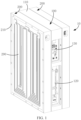
FIG. 1 is a schematic three-dimensional structural view of an energy storage device according to an embodiment. -
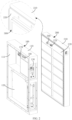
FIG. 2 is a schematic view of an exploded structure of the energy storage device shown inFIG. 1 with one battery module removed. -
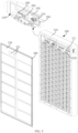
FIG. 3 is a schematic structural view ofFIG. 2 from another perspective. -
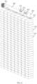
FIG. 4 is a schematic three-dimensional cross-sectional structural view of the energy storage device shown inFIG. 1 with one battery module removed. -
FIG. 5 is an exploded structural view of the battery module in the energy storage device shown inFIG. 1 . -
FIG. 6 is a partial structural view of the battery module shown inFIG. 5 with the box and the cover plate removed. -
FIG. 7 is a first partial plan cross-sectional structural view of the energy storage device shown inFIG. 1 . -
FIG. 8 is a second partial plan cross-sectional structural view of the energy storage device shown inFIG. 1 . - Reference signs:
energy storage device 10,electrical module 100,electrical cabinet 110,receiving cavity 111,limiting groove 112,liquid cooling unit 120,controller 130, secondliquid cooling connector 160, secondelectrical connector 170,bolt 180,battery module 200,box 210,accommodation cavity 211,cover plate 220,mounting hole 221,cell 230,second sealing member 240,fixing member 250, firstliquid cooling connector 260, firstelectrical connector 270,copper bar 280,liquid cooling plate 290,positive terminal 201,negative terminal 202,first sealing member 300,positioning pin 410,positioning hole 420. - In order to make the above objects, features and advantages of the present application more obvious and understandable, the specific implementations of the present application will be described in detail below with reference to the accompanying drawings. In the following description, numerous specific details are set forth in order to provide a thorough understanding of the present application. However, the present application can be implemented in many other ways different from those described here. Those skilled in the art can make similar improvements without violating the connotation of the present application. Therefore, the present application is not limited by the specific embodiments disclosed below.
- In the description of the present application, it should be understood that if the terms "center", "longitudinal", "transverse", "length", "width", "thickness", "upper", "lower", "front", "back", "left", "right", "vertical", "horizontal", "top", "bottom", "inside", "outside", "clockwise", "counterclockwise", "axial", "radial", "circumferential", etc. appear, the orientations or positional relationships indicated by these terms are based on the orientations or positional relationships shown in the drawings, which is only for the convenience of describing the present application and simplifying the description, rather than indicating or implying that the device or element referred to must have a specific orientation, be constructed and operate in a specific orientation, and therefore these terms cannot be construed as a limitation on the present application.
- In addition, if the terms "first" and "second" appear, these terms are used for descriptive purposes only and cannot be understood as indicating or implying the relative importance or implicitly indicating the quantity of the indicated technical features. Therefore, features defined as "first" and "second" may explicitly or implicitly include at least one of these features. In the description of the present application, if the term "a plurality of" or "multiple" appears, the meaning of "a plurality of" or "multiple" is at least two, such as two, three, etc., unless otherwise expressly and specifically limited.
- In the present application, unless otherwise expressly stated and limited, if the terms "mount", "connect", "couple", "fix", etc. appear, these terms should be understood in a broad sense. For example, it can be a fixed connection or a detachable connection, or it can be integrated; it can be a mechanical connection or an electrical connection; it can be a direct connection or an indirect connection through an intermediate medium; it can be an internal connection between two elements or the interaction between two elements, unless otherwise expressly limited. For those of ordinary skill in the art, the specific meanings of the above terms in the present application can be understood according to specific circumstances.
- In the present application, unless otherwise explicitly stated and limited, if a first feature is "on" or "below" a second feature or similar descriptions, the meaning may be that the first and second features are in direct contact, or the first and second features are in indirect contact through an intermediary. Furthermore, the first feature "on", "above" and "over" the second feature may mean that the first feature is directly above or diagonally above the second feature, or simply means that the first feature has a greater horizontal height than the second feature. The first feature "under", "below" and "beneath" the second feature may mean that the first feature is directly below or diagonally below the second feature, or simply means that the first feature has a smaller horizontal height than the second feature.
- It should be noted that if an element is referred to as being "fixed to" or "disposed on" another element, it can be directly on another element or an intervening element may also be present. If an element is said to be "connected" to another element, it can be directly connected to another element or there may also be an intervening element. If present, the terms "vertical", "horizontal", "upper", "lower", "left", "right" and similar expressions used in the present application are for illustrative purposes only and are not meant to be exclusive implementation.
- For the traditional energy storage devices, the sealing treatment will lead to a complex structure of the energy storage device, thereby increasing the manufacturing cost of the energy storage device.
- One technical problem solved by the present application is how to reduce the manufacturing cost of the energy storage device after sealing treatment.
- Referring to
FIG. 1 ,FIG. 2 andFIG. 3 , anenergy storage device 10 provided in an embodiment of the present application includes anelectrical module 100, abattery module 200 and afirst sealing member 300. Thebattery module 200 can be disposed on theelectrical module 100 in a stacked manner, and thefirst sealing member 300 is pressed between theelectrical module 100 and thebattery module 200. - Referring to
FIG. 2 ,FIG. 3 andFIG. 4 , theelectrical module 100 includes anelectrical cabinet 110. Theelectrical cabinet 110 is provided with areceiving cavity 111. Thereceiving cavity 111 is used to accommodate other component(s) of theelectrical module 100. Theelectrical cabinet 110 is also provided with alimiting groove 112. The limitinggroove 112 may be formed by recessing the surface of theelectrical cabinet 110 to a set depth. Thelimiting groove 112 is arranged around the opening of thereceiving cavity 111. The first sealingmember 300 may be a sealing ring. The first sealingmember 300 cooperates with thelimiting groove 112. The limitinggroove 112 plays a good positioning role for thefirst sealing member 300 and improves the assembly efficiency and accuracy of thefirst sealing member 300. Thelimiting groove 112 may also be provided on thebattery module 200. When thebattery module 200 is stacked on theelectrical module 100, thebattery module 200 may cover thereceiving cavity 111, so that thefirst sealing member 300 is pressed between theelectrical module 100 and thebattery module 200, and then thefirst sealing member 300 plays a good sealing role on thereceiving cavity 111. - If the electrical module and the battery module share one cabinet, the cabinet is separated by a partition to form an electrical compartment and a battery compartment. The electrical module is housed in the electrical compartment, and the battery module is housed in the battery compartment. An electrical cabinet door is used to cap the battery compartment, and a battery cabinet door is used to cap the battery compartment. Therefore, it is necessary to fill a gap between the electrical cabinet door and the cabinet to seal the electrical compartment. It is also necessary to fill a gap between the battery cabinet door and the cabinet to seal the battery compartment. It is also necessary to provide a sealing member on the partition to seal and isolate the electrical compartment and the battery compartment. This will make the sealing structure of the entire energy storage device more complex, thereby increasing the manufacturing cost of the energy storage device after sealing treatment.
- For the
energy storage device 10 in the above embodiment, thebattery module 200 directly seals thereceiving cavity 111 of theelectrical module 100 through thefirst sealing member 300, so that thebattery module 200 can serve as a cabinet door for sealing thereceiving cavity 111 of theelectrical module 100, thereby eliminating the need to provide an additional cabinet door on theelectrical cabinet 110 for sealing thereceiving cavity 111. This will simplify the sealing structure of theenergy storage device 10, thereby reducing the manufacturing cost of theenergy storage device 10 after the sealing treatment. It can be understood that by sealing the receivingcavity 111, external dust and liquid droplets can be effectively prevented from entering the receivingcavity 111, thereby avoiding corrosion of component(s) in the receivingcavity 111 or causing short circuit. - Referring to
FIG. 1 , in some embodiments, thebattery module 200 and theelectrical module 100 may have substantially the same structure. For example, both may be substantially rectangular, and the coverage areas of the two may be substantially the same. When thebattery module 200 and theelectrical module 100 are stacked on each other, the outer lateral surfaces of theelectrical module 100 and thebattery module 200 may be flush with each other, which can improve the overall consistency of the appearance of the entireenergy storage device 10, and also facilitates the installation and transportation of theenergy storage device 10. After thebattery module 200 and theelectrical module 100 are stacked on each other, thebattery module 200 and theelectrical module 100 may be connected through a fastener such as a bolt 180 (as shown inFIG. 7 ), so that thebattery module 200 and theelectrical module 100 form a detachable connection relationship. - Referring to
FIG. 1 , in some embodiments, for example, the receivingcavity 111 of theelectrical cabinet 110 has two openings, and the two openings are spaced apart along the thickness direction of theelectrical cabinet 110. In this case, twobattery modules 200 need to be provided, and the twobattery modules 200 are positioned on opposite sides of theelectrical cabinet 110 in the thickness direction, thereby sealing the two openings of the receivingcavity 111. Therefore, theenergy storage device 10 includes oneelectrical module 100 and twobattery modules 200. For another example, the receivingcavity 111 of theelectrical cabinet 110 has one opening. In this case, only onebattery module 200 is needed. The opening of the receivingcavity 111 is sealed by thebattery module 200. Therefore, theenergy storage device 10 includes oneelectrical module 100 and onebattery module 200. - Referring to
FIG. 4 ,FIG. 5 andFIG. 6 , in some embodiments, thebattery module 200 includes abox 210, acover plate 220, acell 230 and asecond sealing member 240. Anaccommodation cavity 211 is provided in thebox 210. The number of thecell 230 may be multiple, and themultiple cells 230 may be arranged in a matrix and disposed in theaccommodation cavity 211, and all thecells 230 are placed bare in theaccommodation cavity 211. A positioning groove may be provided on thebox 210. The positioning groove may be formed by recessing the surface of thebox 210 toward thecover plate 220 to a set depth. The positioning groove is provided around the opening of theaccommodation cavity 211. Thesecond sealing member 240 may be a sealing ring. Thesecond sealing member 240 cooperates with the positioning groove. The positioning groove plays a good positioning role for thesecond sealing member 240 and improves the assembly efficiency and accuracy of thesecond sealing member 240. The positioning groove may also be provided on the surface of thecover plate 220 facing thebox 210. When thebattery module 200 is placed on thebox 210, thecover plate 220 covers theaccommodation cavity 211, so that thesecond sealing member 240 is pressed between thecover plate 220 and thebox 210, and then thesecond sealing member 240 has a good sealing effect on theaccommodation cavity 211. Through the joint action of thefirst sealing member 300 and thesecond sealing member 240, the receivingcavity 111 of theelectrical module 100 and theaccommodation cavity 211 of thebattery module 200 can be sealed and isolated, thereby eliminating the need for additional sealing members for isolating and sealing the receivingcavity 111 and theaccommodation cavity 211 from each other, thus further simplifying the sealing structure of theenergy storage device 10 and reducing the manufacturing cost of theenergy storage device 10 after the sealing treatment. It can be understood that by sealing theaccommodation cavity 211, external dust and liquid droplets can be effectively prevented from entering theaccommodation cavity 211, thereby avoiding corrosion of thecells 230 and other component(s) in theaccommodation cavity 211 or causing a short circuit. When thebattery module 200 is stacked on theelectrical module 100, thefirst sealing member 300 may be pressed between thecover plate 220 of thebattery module 200 and theelectrical cabinet 110 of theelectrical module 100. - It is assumed that the battery module of the energy storage device adopts a mode including a plurality of battery units, that is, a plurality of battery units are stacked each other to form a battery module. Each battery unit includes a casing, a cover, cells and a sealing member. The number of cells can be multiple. The multiple battery cells are contained in the inner cavity of the casing. The cover is used to cap the inner cavity of the casing. The sealing member is located between the casing and the cover, so that the sealing member seals the inner cavity of the casing. This will cause the battery module to have multiple casings, covers and sealing members, thereby making the structure of the
energy storage device 10 more complex and increasing the manufacturing cost of the energy storage device. - For the
battery module 200 in the above embodiment, only onebox 210, onecover plate 220 and onesecond sealing member 240 are provided, and allcells 230 are placed naked in theaccommodation cavity 211 of thebox 210. There is no need to package thecell 230 through the casing, the cover and the sealing member to form multiple battery units. It can be understood that allcells 230 share onebox 210,cover plate 220 and second sealingmember 240, so that the provision of multiple casings, covers and sealing members for forming the battery units is eliminated. This will simplify the structure of theenergy storage device 10 and reduce the manufacturing cost of theenergy storage device 10. - Referring to
FIG. 4 ,FIG. 5 andFIG. 6 , in some embodiments, thebattery module 200 may also include a fixingmember 250, a firstliquid cooling connector 260, a firstelectrical connector 270, acopper bar 280, aliquid cooling plate 290 and a third sealing member. The fixingmember 250 may be arranged in theaccommodation cavity 211, theliquid cooling plate 290 is connected to thebox 210, a heat exchange channel is provided in theliquid cooling plate 290, two ends of the heat exchange channel are respectively an inlet and an outlet, and the liquid flows in from the inlet and out from the outlet. The heat generated by the operation of thecell 230 can be conducted to theliquid cooling plate 290. When a liquid with lower temperature is introduced into the heat exchange channel, the liquid will absorb the heat conducted to theliquid cooling plate 290 in the heat exchange channel, and the liquid absorbing the heat will be discharged from the outlet, so that the liquid can dissipate and cool down theliquid cooling plate 290 and theaccommodation cavity 211, ensuring that thecell 230 works in a reasonable temperature environment and preventing thecell 230 from being damaged due to excessive temperature. - The fixing
member 250 may be a plate-like structure, and the firstliquid cooling connector 260 and the firstelectrical connector 270 are both arranged on the fixingmember 250, so that the fixingmember 250 serves as a carrier for the firstliquid cooling connector 260 and the firstelectrical connector 270. The firstliquid cooling connector 260 may include a liquid inlet pipe and a liquid outlet pipe. Liquid with a lower temperature enters the heat exchange channel through the liquid inlet pipe and the inlet. After absorbing heat, liquid with a higher temperature will flow into the liquid outlet pipe from the heat exchange channel through the outlet. Referring toFIG. 6 , the number ofcopper bars 280 may be two. The positive interface of the firstelectrical connector 270 can be electrically connected to thepositive terminal 201 of thebattery module 200 through one of the copper bars 280. The negative interface of the firstelectrical connector 270 can be electrically connected to thenegative terminal 202 of thebattery module 200 through theother copper bar 280. Thepositive terminal 201 and thenegative terminal 202 extend in different directions. For example, thepositive terminal 201 may extend along the width direction of thebattery module 200, while thenegative terminal 202 may extend along the thickness direction of thebattery module 200. This will facilitate the layout of the twocopper bars 280, thereby simplifying the structure of thebattery module 200. - The first
liquid cooling connector 260 and the firstelectrical connector 270 can both be fixed on a fixing plate through a snap connection, so that the firstliquid cooling connector 260 and the firstelectrical connector 270 form a quick-plug and quick-change structure, to prevent the firstliquid cooling connector 260 and the firstelectrical connector 270 from being installed on the fixingmember 250 through fasteners such as bolts. During the assembly process, the firstliquid cooling connector 260 and the firstelectrical connector 270 can be assembled by a robot, so that the automated assembly of thebattery module 200 can be realized, thereby improving the assembly efficiency of thebattery module 200 and the entireenergy storage device 10 to reduce the manufacturing cost. - If the battery module still uses a mode in which a plurality of battery units are included, the casing of each battery unit needs to have an input port and an output port for liquid inflow and outflow to dissipate and cool down the cells in the battery unit, this will require the installation of connecting pipes at the input and output ports of each battery unit, thereby increasing the number of connecting pipes used and increasing the manufacturing cost of the energy storage device. Moreover, there are a high-voltage connection line and a low-voltage connection line between two adjacent battery units. The high-voltage connection line and low-voltage connection line are used to electrically connect the two battery units. In view of the large number of high-voltage connection lines and low-voltage connection lines, the manufacturing cost of the energy storage device will be further increased.
- For the
energy storage device 10 in the above embodiment, since all thecells 230 in thebattery module 200 share oneliquid cooling plate 290, only one inlet and outlet are provided on theliquid cooling plate 290, thereby reducing the number of connecting pipes used, reducing the probability of failure of theenergy storage device 10 during manufacturing and operation, thereby reducing the manufacturing cost of theenergy storage device 10 and improving the stability and reliability of the operation of theenergy storage device 10. In addition, allcells 230 are placed naked in theaccommodation cavity 211, which eliminates the need for providing the high-voltage connection line and the low-voltage connection line between two adjacent cells, thereby further reducing the manufacturing cost of theenergy storage device 10. - Referring to
FIG. 4 ,FIG. 5 andFIG. 6 , in some embodiments, thecover plate 220 is provided with a mountinghole 221. The mountinghole 221 is a through hole that runs through theentire cover plate 220 along the thickness direction of thecover plate 220. The firstliquid cooling connector 260 is inserted into one of the mountingholes 221, and the firstelectrical connector 270 is inserted into the other mountinghole 221. The third sealing member may be a sealing ring, and the third sealing member is pressed between thecover plate 220 and the fixingmember 250 to seal the mountinghole 221. For example, the number of the third sealing members is two, and one third sealing member is arranged around the firstliquid cooling connector 260 to seal the mountinghole 221 for the firstliquid cooling connector 260 to pass through, and the other third sealing member is disposed around the firstelectrical connector 270 to seal the mountinghole 221 for the firstelectrical connector 270 to pass through. - Referring to
FIGS. 2 ,3 and4 , in some embodiments, theelectrical module 100 further includes aliquid cooling unit 120, acontroller 130, a secondliquid cooling connector 160 and a secondelectrical connector 170. Theliquid cooling unit 120 and thecontroller 130 may both be located in the receivingcavity 111. Theliquid cooling unit 120 is connected to the secondliquid cooling connector 160, and the secondliquid cooling connector 160 is connected to the firstliquid cooling connector 260, so that the secondliquid cooling connector 160 is connected between theliquid cooling unit 120 and the firstliquid cooling connector 260. The liquid with a lower temperature is output through theliquid cooling unit 120, and enters the heat exchange channel of theliquid cooling plate 290 from the inlet sequentially through the secondliquid cooling connector 160 and the firstliquid cooling connector 260. After absorbing heat, the liquid with a higher temperature returns to theliquid cooling unit 120 from the outlet of the heat exchange channel sequentially through the firstliquid cooling connector 260 and the secondliquid cooling connector 160, thus realizing the heat dissipation of thecell 230 by theliquid cooling unit 120. The secondelectrical connector 170 is connected between thecontroller 130 and the firstelectrical connector 270. Since the firstelectrical connector 270 is electrically connected to the positive and to the negative electrodes of thebattery module 200 respectively, this allows thecontroller 130 to control the voltage of thebattery module 200 through the secondelectrical connector 170 and the firstelectrical connector 270, so that thebattery module 200 forms high-voltage and low-voltage electrical connections through thecontroller 130. - In some embodiments, the second
liquid cooling connector 160 and the secondelectrical connector 170 may both be fixed on theelectrical cabinet 110 through a snap connection, such that the secondliquid cooling connector 160 and the secondelectrical connector 170 forms a quick-plug and quick-change structure to prevent the secondliquid cooling connector 160 and the secondelectrical connector 170 from being installed on theelectrical cabinet 110 through fasteners such as bolts. During the assembly process, the secondliquid cooling connector 160 and the secondelectrical connector 170 can be assembled by a robot, so that the automated assembly of theelectrical module 100 can be realized, thereby improving the assembly efficiency of theelectrical module 100 and the entireenergy storage device 10 to reduce the manufacturing cost. - In some embodiments, one of the first
liquid cooling connector 260 and the secondliquid cooling connector 160 is a connecting plug and the other is a connecting socket. Through the assembly manner of the connecting plug and the connecting socket, the assembly efficiency between the firstliquid cooling connector 260 and the secondliquid cooling connector 160 can be improved, and it also enables the firstliquid cooling connector 260 and the secondliquid cooling connector 160 to form a detachable connection relationship. Similarly, one of the firstelectrical connector 270 and the secondelectrical connector 170 is a connecting plug and the other is a connecting socket. Through the assembly manner of the connecting plug and the connecting socket, the assembly efficiency between the firstelectrical connector 270 and the secondelectrical connector 170 can be improved, and it also enables the firstelectrical connector 270 and the secondelectrical connector 170 to form a detachable connection relationship. In view of the improved assembly efficiency between the firstliquid cooling connector 260 and the secondliquid cooling connector 160 and between the firstelectrical connector 270 and the secondelectrical connector 170, the assembly efficiency of theenergy storage device 10 can also be improved so as to reduce the manufacturing cost. - Referring to
FIG. 8 , in some embodiments, for theelectrical cabinet 110 on theelectrical module 100 and thebox 210 on thebattery module 200, one of theelectrical cabinet 110 and thebox 210 may be provided with apositioning hole 420 and the other one may be provided with apositioning pin 410. For example, theelectrical cabinet 110 may be provided with apositioning hole 420, and thebox 210 may be provided with apositioning pin 410. For another example, theelectrical cabinet 110 may be provided with apositioning pin 410, and thebox 210 may be provided with apositioning hole 420. During the assembly process of theelectrical module 100 and thebattery module 200, through the cooperation between thepositioning hole 420 and thepositioning pin 410, the assembly efficiency and assembly accuracy of theelectrical module 100 and thebattery module 200 can be improved. - Each of the battery modules further includes a third sealing member. The cover plate is provided with a mounting hole for insertion of the first liquid cooling connector and the first electrical connector. The third sealing member is pressed between the cover plate and the fixing member to seal the mounting hole.
- The first liquid cooling connector and the first electrical connector are both snap-connected to the fixing member.
- Each of the battery modules further includes a connecting copper bar. The first electrical connector is electrically connected respectively to a positive terminal and to a negative terminal of the battery module through the connecting copper bar. The positive terminal extends along a width direction of the battery module. The negative terminal extends along a thickness direction of the battery module.
- The electrical module further includes a liquid cooling unit, a controller, a second liquid cooling connector and a second electrical connector. The liquid cooling unit and the controller are located in the receiving cavity. The second liquid cooling connector and the second electrical connector are both arranged on the electrical cabinet through a snap connection, the second liquid cooling connector is connected between the liquid cooling unit and the first liquid cooling connector, and the second electrical connector is connected between the controller and the first electrical connector.
- One of the first liquid cooling connector and the second liquid cooling connector is a connecting plug and the other is a connecting socket; one of the first electrical connector and the second electrical connector is a connecting plug and the other is a connecting socket.
- The first sealing member is pressed between the cover plate and the electrical cabinet.
- Outer lateral surfaces of the electrical module and the battery modules are flush with each other.
- The electrical cabinet is recessed and provided with a limiting groove arranged around the receiving cavity, and the first sealing member cooperates with the limiting groove.
- At least one of following solutions are also included:
- the electrical module and the battery modules are bolted together;
- one of the electrical module and the battery modules includes a positioning pin and the other is provided with a positioning hole, and the positioning pin cooperates with the positioning hole.
- One technical effect of the present application is: the battery module is disposed on the electrical module and covers the receiving cavity, and the first sealing member is pressed between the battery module and the electrical module to seal the receiving cavity, that is, the battery module directly seals the receiving cavity of the electrical module through the first sealing member, so that the battery module can serve as a cabinet door for sealing the receiving cavity of the electrical module, thereby eliminating the need for providing an additional cabinet door on the electrical cabinet for sealing the receiving cavity, which simplifies the sealing structure of the energy storage device, thereby reducing the manufacturing cost of the energy storage device after sealing treatment.
- All cells are placed bare in the accommodation cavity and share the liquid cooling plate, thus reducing the number of connecting pipes used and reducing the probability of failure of the energy storage device during manufacturing and operation, thereby reducing the manufacturing cost of the energy storage device and improving the stability and reliability of the operation of the device energy storage. In addition, it is possible to eliminate the need for providing the high-voltage connection line and the low-voltage connection line between two adjacent cells, thereby further reducing the manufacturing cost of the energy storage device.
- The technical features of the above-described embodiments can be combined in any way. To simplify the description, not all possible combinations of the technical features in the above-described embodiments are described. However, as long as there is no contradiction in the combinations of these technical features, all the combinations should be considered to be within the scope of the present specification.
- The above-described embodiments only express several implementations of the present application, and their descriptions are relatively specific and detailed, but they should not be construed as limiting the scope of the patent application. It should be noted that, for those of ordinary skill in the art, several modifications and improvements can be made without departing from the concept of the present application, and these all fall within the protection scope of the present application. Therefore, the protection scope of this patent application should be determined by the appended claims.
Claims (10)
- An energy storage device (10), comprising:an electrical module (100), wherein the electrical module (100) comprises an electrical cabinet (110) provided with a receiving cavity (111);battery modules (200), wherein a number of the battery modules (200) is two, the electrical module (100) is sandwiched between the two battery modules (200), and the two battery modules (200) respectively cover both ends of the receiving cavity (111); andfirst sealing members (300), wherein the first sealing members (300) are arranged around the receiving cavity (111), and the first sealing members (300) are respectively pressed between the battery modules (200) and the electrical module (100) to seal the receiving cavity (111);wherein each of the battery modules (200) comprises a box (210), a cover plate (220), a cell (230) and a second sealing member (240), the box (210) is provided with an accommodation cavity (211), the cell (230) is accommodated in the accommodation cavity (211), the cover plate (220) is provided on the box (210) and caps the accommodation cavity (211), the second sealing member (240) is arranged around the accommodation cavity (211), and the second sealing member (240) is pressed between the cover plate (220) and the box (210) to seal the accommodation cavity (211);each of the battery modules (200) further comprises a liquid cooling plate (290) connected to the box (210) and used to cool down the cells (230), and the cell (230) is placed naked in the accommodation cavity (211) and share the liquid cooling plate (290);each of the battery modules (200) further comprises a fixing member (250), a first liquid cooling connector (260) and a first electrical connector (270), the fixing member (250) is connected to the box (210) and is located in the accommodation cavity (211), the first liquid cooling connector (260) and the first electrical connector (270) are both arranged on the fixing member (250), the first liquid cooling connector (260) is connected to the liquid cooling plate (290) and the electrical module (100), and the first electrical connector (270) is electrically connected to an electrode of the battery module (200) and to the electrical module (100).
- The energy storage device (10) according to claim 1, wherein each of the battery modules (200) further comprises a third sealing member, the cover plate (220) is provided with a mounting hole (221) for insertion of the first liquid cooling connector (260) and the first electrical connector (270), and the third sealing member is pressed between the cover plate (220) and the fixing member (250) to seal the mounting hole (221).
- The energy storage device (10) according to claim 1, wherein the first liquid cooling connector (260) and the first electrical connector (270) are both snap-connected to the fixing member (250).
- The energy storage device (10) according to claim 1, wherein each of the battery modules (200) further comprises a connecting copper bar, and the first electrical connector (270) is respectively connected to a positive terminal (201) and a negative terminal (202) of the battery module (200) through the connecting copper bar, the positive terminal (201) extends along a width direction of the battery module (200), and the negative terminal (202) extends along a thickness direction of the battery module (200).
- The energy storage device (10) according to claim 1, wherein the electrical module (100) further comprises a liquid cooling unit (120), a controller (130), a second liquid cooling connector (160) and a second electrical connector (170), the liquid cooling unit (120) and the controller (130) are located in the receiving cavity (111), the second liquid cooling connector (160) and the second electrical connector (170) are both arranged on the electrical cabinet (110) through a snap connection, the second liquid cooling connector (160) is connected between the liquid cooling unit (120) and the first liquid cooling connector (260), and the second electrical connector (170) is connected between the controller (130) and the first electrical connector (270).
- The energy storage device (10) according to claim 5, wherein one of the first liquid cooling connector (260) and the second liquid cooling connector (160) is a connecting plug and the other is a connecting socket; one of the first electrical connector (270) and the second electrical connector (170) is a connecting plug and the other is a connecting socket.
- The energy storage device (10) according to claim 1, wherein the first sealing member (300) is pressed between the cover plate (220) and the electrical cabinet (110).
- The energy storage device (10) according to claim 1, wherein outer lateral surfaces of the electrical module (100) and the battery modules (200) are flush with each other.
- The energy storage device (10) according to claim 1, wherein the electrical cabinet (110) is recessed and provided with a limiting groove (112) arranged around the receiving cavity (111), and the first sealing member (300) cooperates with the limiting groove (112).
- The energy storage device (10) according to claim 1, wherein
the electrical module (100) and the battery modules (200) are bolted together; and/or
one of the electrical module (100) and the battery modules (200) comprises a positioning pin (410) and the other is provided with a positioning hole (420), and the positioning pin (410) cooperates with the positioning hole (420).
Applications Claiming Priority (1)
| Application Number | Priority Date | Filing Date | Title |
|---|---|---|---|
| CN202310753913.XA CN116544575B (en) | 2023-06-26 | 2023-06-26 | energy storage device |
Publications (2)
| Publication Number | Publication Date |
|---|---|
| EP4485621A1 true EP4485621A1 (en) | 2025-01-01 |
| EP4485621B1 EP4485621B1 (en) | 2025-08-06 |
Family
ID=87445562
Family Applications (1)
| Application Number | Title | Priority Date | Filing Date |
|---|---|---|---|
| EP24174551.2A Active EP4485621B1 (en) | 2023-06-26 | 2024-05-07 | Energy storage device |
Country Status (4)
| Country | Link |
|---|---|
| US (1) | US12095109B1 (en) |
| EP (1) | EP4485621B1 (en) |
| CN (1) | CN116544575B (en) |
| WO (1) | WO2025001163A1 (en) |
Families Citing this family (2)
| Publication number | Priority date | Publication date | Assignee | Title |
|---|---|---|---|---|
| CN116544575B (en) | 2023-06-26 | 2023-09-22 | 厦门海辰储能科技股份有限公司 | energy storage device |
| CN223218406U (en) * | 2024-09-20 | 2025-08-12 | 惠州亿纬锂能股份有限公司 | Battery box and battery pack |
Citations (3)
| Publication number | Priority date | Publication date | Assignee | Title |
|---|---|---|---|---|
| CN208127275U (en) * | 2018-04-02 | 2018-11-20 | 中航锂电(洛阳)有限公司 | A kind of Battery case and the battery case using the Battery case |
| CN213782153U (en) * | 2020-12-23 | 2021-07-23 | 企客信息科技(深圳)有限公司 | Shockproof battery pack structure and electric bicycle |
| CN218456113U (en) * | 2022-09-16 | 2023-02-07 | 湖北亿纬动力有限公司 | Battery pack and power system |
Family Cites Families (15)
| Publication number | Priority date | Publication date | Assignee | Title |
|---|---|---|---|---|
| DE102018222706A1 (en) * | 2018-12-21 | 2020-06-25 | Mahle International Gmbh | accumulator |
| CN209963789U (en) * | 2019-06-11 | 2020-01-17 | 帝亚一维新能源汽车有限公司 | Safe type cabinet that charges |
| CN212648398U (en) | 2020-08-14 | 2021-03-02 | 傲普(上海)新能源有限公司 | Energy storage battery cabinet |
| CN112582721A (en) * | 2020-12-10 | 2021-03-30 | 珠海格力电器股份有限公司 | Energy storage container for improving space utilization rate |
| CN215377551U (en) | 2021-05-21 | 2021-12-31 | 阳光电源股份有限公司 | a battery cabinet |
| CN216698514U (en) * | 2021-09-26 | 2022-06-07 | 华为数字能源技术有限公司 | Energy storage system |
| CN216213779U (en) * | 2021-10-09 | 2022-04-05 | 瑞浦能源有限公司 | Containerized energy storage system |
| CN116762220A (en) * | 2021-10-14 | 2023-09-15 | 宁德时代新能源科技股份有限公司 | Housing device, battery, consumer, and device and method for producing a battery |
| CN217691353U (en) * | 2022-07-21 | 2022-10-28 | 双一力(宁波)电池有限公司 | Battery pack and energy storage system |
| CN218783086U (en) * | 2022-09-20 | 2023-03-31 | 天津市捷威动力工业有限公司 | Battery box |
| CN218385368U (en) * | 2022-09-30 | 2023-01-24 | 阿特斯储能科技有限公司 | Battery module and liquid-cooling energy storage battery pack system with same |
| CN115360460B (en) * | 2022-10-20 | 2023-02-03 | 常州博瑞电力自动化设备有限公司 | Immersed cooling energy storage system |
| CN115911674B (en) * | 2022-11-11 | 2025-11-11 | 厦门海辰储能科技股份有限公司 | Energy storage device |
| CN219697339U (en) * | 2023-05-26 | 2023-09-15 | 云储新能源科技有限公司 | Distributed battery digital energy storage container |
| CN116544575B (en) * | 2023-06-26 | 2023-09-22 | 厦门海辰储能科技股份有限公司 | energy storage device |
-
2023
- 2023-06-26 CN CN202310753913.XA patent/CN116544575B/en active Active
-
2024
- 2024-02-06 WO PCT/CN2024/076205 patent/WO2025001163A1/en not_active Ceased
- 2024-04-24 US US18/644,248 patent/US12095109B1/en active Active
- 2024-05-07 EP EP24174551.2A patent/EP4485621B1/en active Active
Patent Citations (3)
| Publication number | Priority date | Publication date | Assignee | Title |
|---|---|---|---|---|
| CN208127275U (en) * | 2018-04-02 | 2018-11-20 | 中航锂电(洛阳)有限公司 | A kind of Battery case and the battery case using the Battery case |
| CN213782153U (en) * | 2020-12-23 | 2021-07-23 | 企客信息科技(深圳)有限公司 | Shockproof battery pack structure and electric bicycle |
| CN218456113U (en) * | 2022-09-16 | 2023-02-07 | 湖北亿纬动力有限公司 | Battery pack and power system |
Also Published As
| Publication number | Publication date |
|---|---|
| CN116544575B (en) | 2023-09-22 |
| EP4485621B1 (en) | 2025-08-06 |
| CN116544575A (en) | 2023-08-04 |
| WO2025001163A1 (en) | 2025-01-02 |
| US12095109B1 (en) | 2024-09-17 |
Similar Documents
| Publication | Publication Date | Title |
|---|---|---|
| CN110140233B (en) | Battery system and vehicle comprising same | |
| EP4485621B1 (en) | Energy storage device | |
| CN107946503B (en) | Battery module carrier and battery system | |
| JP7666850B2 (en) | Battery module containing insulating oil and battery pack containing the same | |
| US12342512B2 (en) | Power electrical apparatus comprising two power electronic modules and an integrated cooling system | |
| US20250300262A1 (en) | Shunt device, cooling device, battery pack and electrical device | |
| JP7728421B2 (en) | Battery module and battery system | |
| CN111934052A (en) | Liquid cooling laminate polymer battery module, battery system and electric vehicle | |
| CN218300059U (en) | Battery box and power battery | |
| US20250219189A1 (en) | Battery Pack with Improved Cooling Structure and Device Including the Same | |
| CN214043782U (en) | Liquid-cooled battery box and battery pack | |
| CN223514148U (en) | A battery pack housing with liquid cooling function | |
| CN113782897A (en) | Battery pack and vehicle having the same | |
| CN119812564B (en) | Battery packs and electrical equipment | |
| CN222422157U (en) | Immersed battery pack and energy storage system | |
| CN219892326U (en) | Battery pack | |
| CN113782903A (en) | Battery pack and vehicle having the same | |
| CN119725874A (en) | A battery module and an electric device | |
| US20240372202A1 (en) | Battery housing | |
| JP7262496B2 (en) | Connectors and energy packs | |
| US20250385370A1 (en) | Battery module and battery pack including the same | |
| US20260045589A1 (en) | Battery cell module assembly | |
| US12206082B2 (en) | Battery module and manufacturing method thereof | |
| CN111435840A (en) | Signal transmission parts, battery modules, battery systems and electric vehicles | |
| CN121484354A (en) | Battery packs and energy storage devices |
Legal Events
| Date | Code | Title | Description |
|---|---|---|---|
| PUAI | Public reference made under article 153(3) epc to a published international application that has entered the european phase |
Free format text: ORIGINAL CODE: 0009012 |
|
| STAA | Information on the status of an ep patent application or granted ep patent |
Free format text: STATUS: THE APPLICATION HAS BEEN PUBLISHED |
|
| STAA | Information on the status of an ep patent application or granted ep patent |
Free format text: STATUS: REQUEST FOR EXAMINATION WAS MADE |
|
| AK | Designated contracting states |
Kind code of ref document: A1 Designated state(s): AL AT BE BG CH CY CZ DE DK EE ES FI FR GB GR HR HU IE IS IT LI LT LU LV MC ME MK MT NL NO PL PT RO RS SE SI SK SM TR |
|
| 17P | Request for examination filed |
Effective date: 20241129 |
|
| RBV | Designated contracting states (corrected) |
Designated state(s): AL AT BE BG CH CY CZ DE DK EE ES FI FR GB GR HR HU IE IS IT LI LT LU LV MC ME MK MT NL NO PL PT RO RS SE SI SK SM TR |
|
| GRAP | Despatch of communication of intention to grant a patent |
Free format text: ORIGINAL CODE: EPIDOSNIGR1 |
|
| STAA | Information on the status of an ep patent application or granted ep patent |
Free format text: STATUS: GRANT OF PATENT IS INTENDED |
|
| RIC1 | Information provided on ipc code assigned before grant |
Ipc: H01M 50/262 20210101ALI20250224BHEP Ipc: H01M 50/296 20210101ALI20250224BHEP Ipc: H01M 50/271 20210101ALI20250224BHEP Ipc: H01M 10/655 20140101ALI20250224BHEP Ipc: H01M 50/209 20210101ALI20250224BHEP Ipc: H01M 10/613 20140101AFI20250224BHEP |
|
| INTG | Intention to grant announced |
Effective date: 20250310 |
|
| RAP1 | Party data changed (applicant data changed or rights of an application transferred) |
Owner name: HITHIUM TECH HK LIMITED |
|
| GRAS | Grant fee paid |
Free format text: ORIGINAL CODE: EPIDOSNIGR3 |
|
| GRAA | (expected) grant |
Free format text: ORIGINAL CODE: 0009210 |
|
| STAA | Information on the status of an ep patent application or granted ep patent |
Free format text: STATUS: THE PATENT HAS BEEN GRANTED |
|
| AK | Designated contracting states |
Kind code of ref document: B1 Designated state(s): AL AT BE BG CH CY CZ DE DK EE ES FI FR GB GR HR HU IE IS IT LI LT LU LV MC ME MK MT NL NO PL PT RO RS SE SI SK SM TR |
|
| REG | Reference to a national code |
Ref country code: GB Ref legal event code: FG4D |
|
| REG | Reference to a national code |
Ref country code: CH Ref legal event code: EP |
|
| REG | Reference to a national code |
Ref country code: DE Ref legal event code: R096 Ref document number: 602024000401 Country of ref document: DE |
|
| REG | Reference to a national code |
Ref country code: IE Ref legal event code: FG4D |
|
| REG | Reference to a national code |
Ref country code: NL Ref legal event code: MP Effective date: 20250806 |
|
| PG25 | Lapsed in a contracting state [announced via postgrant information from national office to epo] |
Ref country code: IS Free format text: LAPSE BECAUSE OF FAILURE TO SUBMIT A TRANSLATION OF THE DESCRIPTION OR TO PAY THE FEE WITHIN THE PRESCRIBED TIME-LIMIT Effective date: 20251206 |
|
| PG25 | Lapsed in a contracting state [announced via postgrant information from national office to epo] |
Ref country code: NO Free format text: LAPSE BECAUSE OF FAILURE TO SUBMIT A TRANSLATION OF THE DESCRIPTION OR TO PAY THE FEE WITHIN THE PRESCRIBED TIME-LIMIT Effective date: 20251106 |
|
| REG | Reference to a national code |
Ref country code: LT Ref legal event code: MG9D |
|
| PG25 | Lapsed in a contracting state [announced via postgrant information from national office to epo] |
Ref country code: PT Free format text: LAPSE BECAUSE OF FAILURE TO SUBMIT A TRANSLATION OF THE DESCRIPTION OR TO PAY THE FEE WITHIN THE PRESCRIBED TIME-LIMIT Effective date: 20251209 |
|
| PG25 | Lapsed in a contracting state [announced via postgrant information from national office to epo] |
Ref country code: FI Free format text: LAPSE BECAUSE OF FAILURE TO SUBMIT A TRANSLATION OF THE DESCRIPTION OR TO PAY THE FEE WITHIN THE PRESCRIBED TIME-LIMIT Effective date: 20250806 |
|
| PG25 | Lapsed in a contracting state [announced via postgrant information from national office to epo] |
Ref country code: HR Free format text: LAPSE BECAUSE OF FAILURE TO SUBMIT A TRANSLATION OF THE DESCRIPTION OR TO PAY THE FEE WITHIN THE PRESCRIBED TIME-LIMIT Effective date: 20250806 Ref country code: NL Free format text: LAPSE BECAUSE OF FAILURE TO SUBMIT A TRANSLATION OF THE DESCRIPTION OR TO PAY THE FEE WITHIN THE PRESCRIBED TIME-LIMIT Effective date: 20250806 |
|
| PG25 | Lapsed in a contracting state [announced via postgrant information from national office to epo] |
Ref country code: GR Free format text: LAPSE BECAUSE OF FAILURE TO SUBMIT A TRANSLATION OF THE DESCRIPTION OR TO PAY THE FEE WITHIN THE PRESCRIBED TIME-LIMIT Effective date: 20251107 |
|
| PG25 | Lapsed in a contracting state [announced via postgrant information from national office to epo] |
Ref country code: SE Free format text: LAPSE BECAUSE OF FAILURE TO SUBMIT A TRANSLATION OF THE DESCRIPTION OR TO PAY THE FEE WITHIN THE PRESCRIBED TIME-LIMIT Effective date: 20250806 |
|
| PG25 | Lapsed in a contracting state [announced via postgrant information from national office to epo] |
Ref country code: LV Free format text: LAPSE BECAUSE OF FAILURE TO SUBMIT A TRANSLATION OF THE DESCRIPTION OR TO PAY THE FEE WITHIN THE PRESCRIBED TIME-LIMIT Effective date: 20250806 |
|
| PG25 | Lapsed in a contracting state [announced via postgrant information from national office to epo] |
Ref country code: PL Free format text: LAPSE BECAUSE OF FAILURE TO SUBMIT A TRANSLATION OF THE DESCRIPTION OR TO PAY THE FEE WITHIN THE PRESCRIBED TIME-LIMIT Effective date: 20250806 Ref country code: BG Free format text: LAPSE BECAUSE OF FAILURE TO SUBMIT A TRANSLATION OF THE DESCRIPTION OR TO PAY THE FEE WITHIN THE PRESCRIBED TIME-LIMIT Effective date: 20250806 |
|
| PG25 | Lapsed in a contracting state [announced via postgrant information from national office to epo] |
Ref country code: RS Free format text: LAPSE BECAUSE OF FAILURE TO SUBMIT A TRANSLATION OF THE DESCRIPTION OR TO PAY THE FEE WITHIN THE PRESCRIBED TIME-LIMIT Effective date: 20251106 |
|
| PG25 | Lapsed in a contracting state [announced via postgrant information from national office to epo] |
Ref country code: ES Free format text: LAPSE BECAUSE OF FAILURE TO SUBMIT A TRANSLATION OF THE DESCRIPTION OR TO PAY THE FEE WITHIN THE PRESCRIBED TIME-LIMIT Effective date: 20250806 |
|
| REG | Reference to a national code |
Ref country code: AT Ref legal event code: MK05 Ref document number: 1823033 Country of ref document: AT Kind code of ref document: T Effective date: 20250806 |
|
| PG25 | Lapsed in a contracting state [announced via postgrant information from national office to epo] |
Ref country code: SM Free format text: LAPSE BECAUSE OF FAILURE TO SUBMIT A TRANSLATION OF THE DESCRIPTION OR TO PAY THE FEE WITHIN THE PRESCRIBED TIME-LIMIT Effective date: 20250806 |
|
| PG25 | Lapsed in a contracting state [announced via postgrant information from national office to epo] |
Ref country code: DK Free format text: LAPSE BECAUSE OF FAILURE TO SUBMIT A TRANSLATION OF THE DESCRIPTION OR TO PAY THE FEE WITHIN THE PRESCRIBED TIME-LIMIT Effective date: 20250806 |
|
| PG25 | Lapsed in a contracting state [announced via postgrant information from national office to epo] |
Ref country code: AT Free format text: LAPSE BECAUSE OF FAILURE TO SUBMIT A TRANSLATION OF THE DESCRIPTION OR TO PAY THE FEE WITHIN THE PRESCRIBED TIME-LIMIT Effective date: 20250806 |
|
| PG25 | Lapsed in a contracting state [announced via postgrant information from national office to epo] |
Ref country code: IT Free format text: LAPSE BECAUSE OF FAILURE TO SUBMIT A TRANSLATION OF THE DESCRIPTION OR TO PAY THE FEE WITHIN THE PRESCRIBED TIME-LIMIT Effective date: 20250806 |
|
| PG25 | Lapsed in a contracting state [announced via postgrant information from national office to epo] |
Ref country code: CZ Free format text: LAPSE BECAUSE OF FAILURE TO SUBMIT A TRANSLATION OF THE DESCRIPTION OR TO PAY THE FEE WITHIN THE PRESCRIBED TIME-LIMIT Effective date: 20250806 |
|
| PG25 | Lapsed in a contracting state [announced via postgrant information from national office to epo] |
Ref country code: EE Free format text: LAPSE BECAUSE OF FAILURE TO SUBMIT A TRANSLATION OF THE DESCRIPTION OR TO PAY THE FEE WITHIN THE PRESCRIBED TIME-LIMIT Effective date: 20250806 Ref country code: SK Free format text: LAPSE BECAUSE OF FAILURE TO SUBMIT A TRANSLATION OF THE DESCRIPTION OR TO PAY THE FEE WITHIN THE PRESCRIBED TIME-LIMIT Effective date: 20250806 |