EP4485570A1 - Negative electrode material, and negative electrode sheet and battery comprising same - Google Patents
Negative electrode material, and negative electrode sheet and battery comprising same Download PDFInfo
- Publication number
- EP4485570A1 EP4485570A1 EP23822720.1A EP23822720A EP4485570A1 EP 4485570 A1 EP4485570 A1 EP 4485570A1 EP 23822720 A EP23822720 A EP 23822720A EP 4485570 A1 EP4485570 A1 EP 4485570A1
- Authority
- EP
- European Patent Office
- Prior art keywords
- negative electrode
- electrode material
- silicon
- carbon
- graphitizing
- Prior art date
- Legal status (The legal status is an assumption and is not a legal conclusion. Google has not performed a legal analysis and makes no representation as to the accuracy of the status listed.)
- Pending
Links
Images

Classifications
-
- H—ELECTRICITY
- H01—ELECTRIC ELEMENTS
- H01M—PROCESSES OR MEANS, e.g. BATTERIES, FOR THE DIRECT CONVERSION OF CHEMICAL ENERGY INTO ELECTRICAL ENERGY
- H01M4/00—Electrodes
- H01M4/02—Electrodes composed of, or comprising, active material
- H01M4/36—Selection of substances as active materials, active masses, active liquids
- H01M4/362—Composites
- H01M4/366—Composites as layered products
-
- C—CHEMISTRY; METALLURGY
- C01—INORGANIC CHEMISTRY
- C01B—NON-METALLIC ELEMENTS; COMPOUNDS THEREOF; METALLOIDS OR COMPOUNDS THEREOF NOT COVERED BY SUBCLASS C01C
- C01B33/00—Silicon; Compounds thereof
- C01B33/113—Silicon oxides; Hydrates thereof
- C01B33/12—Silica; Hydrates thereof, e.g. lepidoic silicic acid
-
- C—CHEMISTRY; METALLURGY
- C01—INORGANIC CHEMISTRY
- C01B—NON-METALLIC ELEMENTS; COMPOUNDS THEREOF; METALLOIDS OR COMPOUNDS THEREOF NOT COVERED BY SUBCLASS C01C
- C01B33/00—Silicon; Compounds thereof
- C01B33/20—Silicates
- C01B33/32—Alkali metal silicates
-
- H—ELECTRICITY
- H01—ELECTRIC ELEMENTS
- H01M—PROCESSES OR MEANS, e.g. BATTERIES, FOR THE DIRECT CONVERSION OF CHEMICAL ENERGY INTO ELECTRICAL ENERGY
- H01M10/00—Secondary cells; Manufacture thereof
- H01M10/05—Accumulators with non-aqueous electrolyte
- H01M10/052—Li-accumulators
- H01M10/0525—Rocking-chair batteries, i.e. batteries with lithium insertion or intercalation in both electrodes; Lithium-ion batteries
-
- H—ELECTRICITY
- H01—ELECTRIC ELEMENTS
- H01M—PROCESSES OR MEANS, e.g. BATTERIES, FOR THE DIRECT CONVERSION OF CHEMICAL ENERGY INTO ELECTRICAL ENERGY
- H01M4/00—Electrodes
- H01M4/02—Electrodes composed of, or comprising, active material
- H01M4/13—Electrodes for accumulators with non-aqueous electrolyte, e.g. for lithium-accumulators; Processes of manufacture thereof
- H01M4/134—Electrodes based on metals, Si or alloys
-
- H—ELECTRICITY
- H01—ELECTRIC ELEMENTS
- H01M—PROCESSES OR MEANS, e.g. BATTERIES, FOR THE DIRECT CONVERSION OF CHEMICAL ENERGY INTO ELECTRICAL ENERGY
- H01M4/00—Electrodes
- H01M4/02—Electrodes composed of, or comprising, active material
- H01M4/36—Selection of substances as active materials, active masses, active liquids
- H01M4/38—Selection of substances as active materials, active masses, active liquids of elements or alloys
- H01M4/386—Silicon or alloys based on silicon
-
- H—ELECTRICITY
- H01—ELECTRIC ELEMENTS
- H01M—PROCESSES OR MEANS, e.g. BATTERIES, FOR THE DIRECT CONVERSION OF CHEMICAL ENERGY INTO ELECTRICAL ENERGY
- H01M4/00—Electrodes
- H01M4/02—Electrodes composed of, or comprising, active material
- H01M4/36—Selection of substances as active materials, active masses, active liquids
- H01M4/58—Selection of substances as active materials, active masses, active liquids of inorganic compounds other than oxides or hydroxides, e.g. sulfides, selenides, tellurides, halogenides or LiCoFy; of polyanionic structures, e.g. phosphates, silicates or borates
- H01M4/5825—Oxygenated metallic salts or polyanionic structures, e.g. borates, phosphates, silicates, olivines
-
- H—ELECTRICITY
- H01—ELECTRIC ELEMENTS
- H01M—PROCESSES OR MEANS, e.g. BATTERIES, FOR THE DIRECT CONVERSION OF CHEMICAL ENERGY INTO ELECTRICAL ENERGY
- H01M4/00—Electrodes
- H01M4/02—Electrodes composed of, or comprising, active material
- H01M4/36—Selection of substances as active materials, active masses, active liquids
- H01M4/58—Selection of substances as active materials, active masses, active liquids of inorganic compounds other than oxides or hydroxides, e.g. sulfides, selenides, tellurides, halogenides or LiCoFy; of polyanionic structures, e.g. phosphates, silicates or borates
- H01M4/583—Carbonaceous material, e.g. graphite-intercalation compounds or CFx
- H01M4/587—Carbonaceous material, e.g. graphite-intercalation compounds or CFx for inserting or intercalating light metals
-
- H—ELECTRICITY
- H01—ELECTRIC ELEMENTS
- H01M—PROCESSES OR MEANS, e.g. BATTERIES, FOR THE DIRECT CONVERSION OF CHEMICAL ENERGY INTO ELECTRICAL ENERGY
- H01M4/00—Electrodes
- H01M4/02—Electrodes composed of, or comprising, active material
- H01M4/62—Selection of inactive substances as ingredients for active masses, e.g. binders, fillers
-
- H—ELECTRICITY
- H01—ELECTRIC ELEMENTS
- H01M—PROCESSES OR MEANS, e.g. BATTERIES, FOR THE DIRECT CONVERSION OF CHEMICAL ENERGY INTO ELECTRICAL ENERGY
- H01M4/00—Electrodes
- H01M4/02—Electrodes composed of, or comprising, active material
- H01M4/62—Selection of inactive substances as ingredients for active masses, e.g. binders, fillers
- H01M4/624—Electric conductive fillers
- H01M4/625—Carbon or graphite
-
- H—ELECTRICITY
- H01—ELECTRIC ELEMENTS
- H01M—PROCESSES OR MEANS, e.g. BATTERIES, FOR THE DIRECT CONVERSION OF CHEMICAL ENERGY INTO ELECTRICAL ENERGY
- H01M4/00—Electrodes
- H01M4/02—Electrodes composed of, or comprising, active material
- H01M4/62—Selection of inactive substances as ingredients for active masses, e.g. binders, fillers
- H01M4/628—Inhibitors, e.g. gassing inhibitors, corrosion inhibitors
-
- C—CHEMISTRY; METALLURGY
- C01—INORGANIC CHEMISTRY
- C01P—INDEXING SCHEME RELATING TO STRUCTURAL AND PHYSICAL ASPECTS OF SOLID INORGANIC COMPOUNDS
- C01P2002/00—Crystal-structural characteristics
- C01P2002/70—Crystal-structural characteristics defined by measured X-ray, neutron or electron diffraction data
- C01P2002/72—Crystal-structural characteristics defined by measured X-ray, neutron or electron diffraction data by d-values or two theta-values, e.g. as X-ray diagram
-
- C—CHEMISTRY; METALLURGY
- C01—INORGANIC CHEMISTRY
- C01P—INDEXING SCHEME RELATING TO STRUCTURAL AND PHYSICAL ASPECTS OF SOLID INORGANIC COMPOUNDS
- C01P2004/00—Particle morphology
- C01P2004/80—Particles consisting of a mixture of two or more inorganic phases
-
- C—CHEMISTRY; METALLURGY
- C01—INORGANIC CHEMISTRY
- C01P—INDEXING SCHEME RELATING TO STRUCTURAL AND PHYSICAL ASPECTS OF SOLID INORGANIC COMPOUNDS
- C01P2006/00—Physical properties of inorganic compounds
- C01P2006/12—Surface area
-
- C—CHEMISTRY; METALLURGY
- C01—INORGANIC CHEMISTRY
- C01P—INDEXING SCHEME RELATING TO STRUCTURAL AND PHYSICAL ASPECTS OF SOLID INORGANIC COMPOUNDS
- C01P2006/00—Physical properties of inorganic compounds
- C01P2006/14—Pore volume
-
- C—CHEMISTRY; METALLURGY
- C01—INORGANIC CHEMISTRY
- C01P—INDEXING SCHEME RELATING TO STRUCTURAL AND PHYSICAL ASPECTS OF SOLID INORGANIC COMPOUNDS
- C01P2006/00—Physical properties of inorganic compounds
- C01P2006/16—Pore diameter
-
- C—CHEMISTRY; METALLURGY
- C01—INORGANIC CHEMISTRY
- C01P—INDEXING SCHEME RELATING TO STRUCTURAL AND PHYSICAL ASPECTS OF SOLID INORGANIC COMPOUNDS
- C01P2006/00—Physical properties of inorganic compounds
- C01P2006/40—Electric properties
-
- H—ELECTRICITY
- H01—ELECTRIC ELEMENTS
- H01M—PROCESSES OR MEANS, e.g. BATTERIES, FOR THE DIRECT CONVERSION OF CHEMICAL ENERGY INTO ELECTRICAL ENERGY
- H01M4/00—Electrodes
- H01M4/02—Electrodes composed of, or comprising, active material
- H01M2004/021—Physical characteristics, e.g. porosity, surface area
-
- H—ELECTRICITY
- H01—ELECTRIC ELEMENTS
- H01M—PROCESSES OR MEANS, e.g. BATTERIES, FOR THE DIRECT CONVERSION OF CHEMICAL ENERGY INTO ELECTRICAL ENERGY
- H01M4/00—Electrodes
- H01M4/02—Electrodes composed of, or comprising, active material
- H01M2004/026—Electrodes composed of, or comprising, active material characterised by the polarity
- H01M2004/027—Negative electrodes
-
- Y—GENERAL TAGGING OF NEW TECHNOLOGICAL DEVELOPMENTS; GENERAL TAGGING OF CROSS-SECTIONAL TECHNOLOGIES SPANNING OVER SEVERAL SECTIONS OF THE IPC; TECHNICAL SUBJECTS COVERED BY FORMER USPC CROSS-REFERENCE ART COLLECTIONS [XRACs] AND DIGESTS
- Y02—TECHNOLOGIES OR APPLICATIONS FOR MITIGATION OR ADAPTATION AGAINST CLIMATE CHANGE
- Y02E—REDUCTION OF GREENHOUSE GAS [GHG] EMISSIONS, RELATED TO ENERGY GENERATION, TRANSMISSION OR DISTRIBUTION
- Y02E60/00—Enabling technologies; Technologies with a potential or indirect contribution to GHG emissions mitigation
- Y02E60/10—Energy storage using batteries
Definitions
- the present disclosure relates to the field of lithium-ion batteries, and specifically, to a negative electrode material, and a negative electrode plate and a battery including the negative electrode material.
- a silicon-carbon composite strategy is proposed in the industry to buffer volume stress of a silicon core during charging and discharging and improve overall conductivity of a composite material.
- a conventional silicon-carbon composite material is prone to problems of silicon-carbon separation or an unstable SEI film on a surface of a composite particle, thereby causing continuous attenuation of a battery capacity and increasing a battery volume.
- the present disclosure provides a negative electrode material, and a negative electrode plate and a battery including the negative electrode material.
- a silicon material in the negative electrode material is distributed on a surface and in a pore of a carbon material.
- the structure provides buffer space for volume expansion of the silicon material. Silicon-carbon separation does not occur in a cycle process.
- a protective layer of the negative electrode material can suppress a reaction between the negative electrode material and an electrolyte solution in a charging/discharging process, thereby improving stability of a SEI film on a surface of a composite particle.
- the battery assembled based on the negative electrode material has a high cycling capacity retention rate and a low cycling volume expansion rate.
- a negative electrode material has a core-shell structure.
- the core-shell structure includes a shell layer and a core.
- the shell layer includes at least one of silicon monoxide, silicon dioxide, or lithium silicate.
- the core includes a carbon material and a silicon material.
- the carbon material includes a non-graphitizing porous carbon material.
- the silicon material includes amorphous silicon.
- the carbon material is a non-graphitizing porous carbon material
- the silicon material is amorphous silicon
- a coverage rate of the shell layer on a surface of the core ranges from 33% to 100%, for example, 33%, 50%, 60%, 70%, 80%, 90%, or 100%.
- the surface of the core is partially or fully coated with the shell layer, that is, the shell layer is a partially or fully coating structure.
- the shell layer has a contrast different from the core when being observed by using a transmission electron microscope (TEM).
- a thickness of the shell layer is less than or equal to 10 nm, for example, ranging from 0.01 nm to 10 nm.
- the thickness of the shell layer is 0.01 nm, 0.05 nm, 0.1 nm, 0.2 nm, 0.5 nm, 0.8 nm, 1 nm, 2 nm, 3 nm, 4 nm, 5 nm, 6 nm, 7 nm, 8 nm, 9 nm, 10 nm, or any value in a range between any two of the foregoing values.
- the amorphous silicon is also referred to as non-crystalline silicon, and lattice networks between some atoms of the amorphous silicon are arranged in disorder.
- a volume expansion rate of the amorphous silicon is less than that of crystalline silicon.
- a non-graphitizing carbon material has a large quantity of pores that may accommodate the amorphous silicon and provide a conductive network for the amorphous silicon.
- a median particle size Dv50 of the amorphous silicon ranges from 0.5 nm to 15 ⁇ m.
- the median particle size Dv50 of the amorphous silicon is 0.5 nm, 1 nm, 2 nm, 3 nm, 4 nm, 5 nm, 6 nm, 7 nm, 8 nm, 9 nm, 10 nm, 20 nm, 30 nm, 40 nm, 50 nm, 60 nm, 70 nm, 80 nm, 90 nm, 100 nm, 200 nm, 300 nm, 400 nm, 500 nm, 600 nm, 700 nm, 800 nm, 900 nm, 1 ⁇ m, 2 ⁇ m, 3 ⁇ m, 4 ⁇ m, 5 ⁇ m, 6 ⁇ m, 7 ⁇ m, 8 ⁇ m, 9 ⁇ m, 10 ⁇ m, 11 ⁇ m, 12
- the amorphous silicon grows along the pores to form a dendritic structure whose particle size may reach a micron level.
- silicon content is low, the amorphous silicon is dispersed in the pores in a form of small particles.
- the non-graphitizing porous carbon material is preferably non-graphitizing porous hard carbon.
- the hard carbon means carbon that is difficult to graphitize at a high temperature above 2500°C.
- the non-graphitizing porous carbon material may be obtained through preparation in a method known in the art, or may be obtained through commercial purchase.
- a specific surface area BET of the non-graphitizing porous carbon material ranges from 200 m 2 /g to 2000 m 2 /g.
- the specific surface area BET of the non-graphitizing porous carbon material is 200 m 2 /g, 300 m 2 /g, 400 m 2 /g, 500 m 2 /g, 600 m 2 /g, 700 m 2 /g, 800 m/g, 900 m 2 /g, 1000 m 2 /g, 1100 m 2 /g, 1200 m 2 /g, 1300 m 2 /g, 1400 m 2 /g, 1500 m 2 /g, 1600 m 2 /g, 1700 m 2 /g, 1800 m 2 /g, 1900 m 2 /g, 2000 m 2 /g, or any value in a range between any two of the foregoing values.
- the specific surface area BET of the non-graphitizing porous carbon material ranges from 900 m 2 /g to 1300 m 2 /g.
- a pore volume of the non-graphitizing porous carbon material ranges from 0.2 cm 3 /g to 1.2 cm 3 /g.
- the pore volume of the non-graphitizing porous carbon material is 0.2 cm 3 /g, 0.25 cm 3 /g, 0.3 cm 3 /g, 0.35 cm 3 /g, 0.4 cm 3 /g, 0.45 cm 3 /g, 0.5 cm 3 /g, 0.55 cm 3 /g, 0.6 cm 3 /g, 0.65 cm 3 /g, 0.7 cm 3 /g, 0.75 cm 3 /g, 0.8 cm 3 /g, 0.85 cm 3 /g, 0.9 cm 3 /g, 0.95 cm 3 /g, 1 cm 3 /g, 1.05 cm 3 /g, 1.1 cm 3 /g, 1.15 cm 3 /g, 1.2 cm 3 /g, or any value in a range between any two of the foregoing values.
- the pore volume of the non-graphitizing porous carbon material ranges from 0.5 cm 3 /g to 0.7 cm 3 /g.
- a pore diameter of the non-graphitizing porous carbon material ranges from 0.5 nm to 100 nm.
- the pore diameter of the non-graphitizing porous carbon material is 0.5 nm, 1 nm, 2 nm, 3 nm, 4 nm, 5 nm, 6 nm, 7 nm, 8 nm, 9 nm, 10 nm, 20 nm, 30 nm, 40 nm, 50 nm, 60 nm, 70 nm, 80 nm, 90 nm, 100 nm, or any value in a range between any two of the foregoing values.
- XRD X-ray powder diffraction
- 0 ⁇ x1 ⁇ 100, and 0 ⁇ x2 ⁇ 100 are 0 ⁇ x1 ⁇ 100, and 0 ⁇ x2 ⁇ 100.
- x1 meets that 0 ⁇ x1 ⁇ 200, it indicates that the negative electrode material includes a carbon material, and the carbon material is a non-graphitizing carbon material.
- x2 meets that 0 ⁇ x2 ⁇ 500, it indicates that the negative electrode material includes a silicon material, and the silicon material is amorphous silicon.
- the negative electrode material corresponds to a binding energy peak in a range of a total spectrum of 96 eV to 105 eV in an X-ray photoelectron spectroscopy (XPS) test
- the binding energy peak in a high resolution spectrum in a range of 90 eV to 110 eV may be divided (by using common peak division software) at least into a binding energy peak 1 whose area is y1 in 97 eV to 100 eV and a binding energy peak 2 whose area is y2 in 101 eV to 104 eV.
- y1 and y2 meet that 0 ⁇ y1/y2 ⁇ 10.
- a silicon-containing compound in which a silicon valence is greater than zero exists on the surface of the negative electrode material.
- a shell layer containing at least one of silicon monoxide, silicon dioxide, or silicate is correspondingly formed on the surface of the negative electrode material.
- a mass content a of a carbon element meets that 25% ⁇ a ⁇ 100%
- a mass content b of a silicon element meets that 0 ⁇ b ⁇ 75%
- 90% ⁇ a + b ⁇ 100% Preferably, 25% ⁇ a ⁇ 95%, and 5% ⁇ b ⁇ 75%.
- a specific surface area BET of the negative electrode material ranges from 0.5 m 2 /g to 20 m 2 /g.
- the specific surface area BET of the negative electrode material is 0.5 m 2 /g, 1 m 2 /g, 2 m 2 /g, 3 m 2 /g, 4 m 2 /g, 5 m 2 /g, 6 m 2 /g, 7 m 2 /g, 8 m 2 /g, 9 m 2 /g, 10 m 2 /g, 11 m 2 /g, 12 m 2 /g, 13 m 2 /g, 14 m 2 /g, 15 m 2 /g, 16 m 2 /g, 17 m 2 /g, 18 m 2 /g, 19 m 2 /g, 20 m 2 /g, or any value in a range between any two of the foregoing values.
- a median particle size Dv50 of the negative electrode material ranges from 1 ⁇ m to 20 ⁇ m.
- the median particle size Dv50 of the negative electrode material is 1 ⁇ m, 1.2 ⁇ m, 1.5 ⁇ m, 1.8 ⁇ m, 2 ⁇ m, 3 ⁇ m, 4 ⁇ m, 5 ⁇ m, 6 ⁇ m, 7 ⁇ m, 8 ⁇ m, 9 ⁇ m, 10 ⁇ m, 11 ⁇ m, 12 ⁇ m, 13 ⁇ m, 14 ⁇ m, 15 ⁇ m, 16 ⁇ m, 17 ⁇ m, 18 ⁇ m, 19 ⁇ m, 20 ⁇ m, or any value in a range between any two of the foregoing values.
- the present disclosure further provides a method for preparing the foregoing negative electrode material.
- the method includes the following steps:
- the carbon material is a non-graphitizing porous carbon material.
- the silane gas is selected from at least one of monosilane, silicoethane, or trichlorosilane.
- the carrier gas is selected from at least one of high-purity argon or high-purity nitrogen.
- a volume ratio of the silane gas to the carrier gas is any ratio, for example, 9:1, 4:1, or 1:1.
- the silane cracking temperature ranges from 300°C to 500°C, for example, 300°C, 350°C, 400°C, 450°C, 480°C, or 500°C.
- a silane cracking time ranges from 6 h to 24 h, for example, 6 h, 7 h, 8 h, 9 h, 10 h, 11 h, 12 h, 13 h, 14 h, 15 h, 16 h, 17 h, 18 h, 19 h, 20 h, 21 h, 22 h, 23 h, or 24 h.
- the silane cracking time ranges from 6 h to 12 h.
- step (1) in the foregoing method the silane is cracked in an inert carrier gas atmosphere at 300°C to 500°C to generate ultra-fine amorphous silicon particles, the amorphous silicon particles are deposited in pores and on surfaces of the non-graphitizing porous carbon material, and the amorphous silicon on the surfaces of the non-graphitizing porous carbon material is converted into silicon monoxide or silicon dioxide in a subsequent air oxidation process.
- a mass-to-volume ratio of the carbon material to the silane ranges from 30 g/10.8 L to 30 g/108 L, for example, 30 g/10.8 L, 30 g/21.6 L, 30 g/32.4 L, 30 g/43.2 L, 30 g/54 L, 30 g/64.8 L, 30 g/75.6 L, 30 g/86.4 L, 30 g/97.2 L, or 30 g/108 L.
- the temperature at which the silicon-carbon composite material is heated and oxidized in air ranges from 50°C to 400°C, for example, 50°C, 100°C, 150°C, 200°C, 250°C, 300°C, 350°C, or 400°C; and a time in which the silicon-carbon composite material is heated and oxidized in air ranges from 0.5 h to 25 h, for example, 0.5 h, 1 h, 2 h, 3 h, 4 h, 5 h, 6 h, 7 h, 8 h, 9 h, 10 h, 11 h, 12 h, 13 h, 14 h, 15 h, 16 h, 17 h, 18 h, 19 h, 20 h, 21 h, 22 h, 23 h, 24 h, or 25 h.
- step (2) in the foregoing method after the silicon-carbon composite material is heated and oxidized in air, the amorphous silicon on the surface of the silicon-carbon composite material may generate silicon monoxide and/or silicon dioxide.
- the lithiation processing is to perform lithiation on silicon monoxide and/or silicon dioxide generated on the surface of the silicon-carbon composite material by using a lithiation reagent to form lithium silicate.
- the lithiation reagent is selected from one or more of lithium biphenyl, lithium naphthalene, or lithium pyrene.
- the lithiation reagent is preferably used in a form of a tetrahydrofuran solution.
- "used in a form of a tetrahydrofuran solution” means dissolving the lithiation reagent in tetrahydrofuran for use.
- a carbon coating layer is usually formed on a surface of a silicon particle (such as nano silicon, a silicon-carbon compound, or a silicon-oxygen compound) in a chemical vapor deposition manner or a polymer pyrolysis manner.
- a silicon particle such as nano silicon, a silicon-carbon compound, or a silicon-oxygen compound
- the carbon coating layer formed in this manner is compact at the beginning, the carbon coating layer expands with a core in an expansion process of silicon particles, and the expanded carbon coating layer becomes loose and porous.
- An electrolyte solution passes through the carbon coating layer to be in contact with the silicon particle core, so that a passivation film is formed on a surface of the silicon particle through a reduction reaction.
- the passivation layer repeatedly grows and becomes thicker as the silicon particle core continuously expands and contracts. This process consumes active lithium in a battery and generates extra gas, which leads to continuous attenuation of a capacity of the battery and a continuous increase of the thickness.
- the inventors of the present disclosure find through research that, if a porous carbon skeleton is used to accommodate an ultra-fine amorphous silicon structure, the carbon skeleton can have a low following volume change when volume expansion and contraction occur on a silicon core, thereby enhancing stability of a passivation layer on a surface of a silicon-carbon composite material.
- a protective layer for example, a silicon oxide layer (that is, silicon monoxide and/or silicon dioxide) or a lithium silicate layer
- a protective layer is disposed on the surface of the foregoing silicon-carbon composite material, which can effectively avoid contact between the electrolyte solution and the amorphous silicon of the core, thereby reducing reduction and decomposition of the electrolyte solution and further improving cycling stability of a battery including the negative electrode material.
- the present disclosure further provides a negative electrode plate.
- the negative electrode plate includes the foregoing negative electrode material.
- the negative electrode plate includes a negative electrode current collector and a negative electrode active material layer on at least one side surface of the negative electrode current collector, and the negative electrode active material layer includes the foregoing negative electrode material.
- the negative electrode active material layer further includes at least one of graphite, hard carbon, or soft carbon.
- the graphite includes artificial graphite and/or natural graphite.
- the negative electrode active material layer further includes a conductive agent.
- the conductive agent is selected from one or more of carbon black, acetylene black, Ketjen black, a carbon fiber, a single-walled carbon nanotube, and a multi-walled carbon nanotube.
- the negative electrode active material layer further includes a binder.
- the binder is selected from one or more of carboxymethyl cellulose, sodium carboxymethyl cellulose, lithium carboxymethyl cellulose, hydroxypropyl cellulose, cellulose acetate, polyethylene, poly(vinyl alcohol), polyvinyl chloride, polyvinyl fluoride, polyvinylpyrrolidone, polytetrafluoroethylene, polypropylene, styrene-butadiene rubber, and epoxy resin.
- the negative electrode current collector is selected from one or more of copper foil, copper foil coated with carbon, or perforated copper foil.
- a mass percentage of each component in the negative electrode active material layer is as follows: 0.5 wt% to 99 wt% of the negative electrode material, 0 wt% to 98.5 wt% of graphite, 0.5 wt% to 15 wt% of the conductive agent, and 0.5 wt% to 15 wt% of the binder.
- the mass percentage of each component in the negative electrode active material layer is as follows: 48 wt% to 95 wt% of graphite, 1 wt% to 50 wt% of the negative electrode material, 1 wt% to 10 wt% of the conductive agent, and 1 wt% to 10 wt% of the binder.
- the negative electrode plate may be obtained by using the following method: The foregoing negative electrode material, optional graphite, the conductive agent, and the binder are mixed in deionized water to obtain a negative electrode slurry.
- the negative electrode current collector is coated with the negative electrode slurry. Then, drying and slicing are performed. Obtained slices are put into a vacuum oven for drying. Finally, rolling and cutting are performed, to obtain the negative electrode plate.
- the negative electrode plate may be specifically obtained by using the following method:
- the foregoing negative electrode material, optional graphite, the conductive agent, and the binder are mixed in deionized water to obtain a negative electrode slurry.
- the negative electrode current collector is coated with the negative electrode slurry. Then, drying is performed at 80°C, and then slicing is performed. Obtained slices are put into a vacuum oven for drying at 100°C for 12 h. Finally, rolling and cutting are performed, to obtain the negative electrode plate.
- the present disclosure further provides a battery.
- the battery includes the foregoing negative electrode material or includes the foregoing negative electrode plate.
- the battery is a lithium-ion battery.
- the battery further includes a positive electrode plate.
- the positive electrode plate has a conventional positive electrode plate structure, and includes, for example, a positive electrode current collector and a positive electrode active material layer coated on at least one surface of the positive electrode current collector.
- the positive electrode active material layer includes a positive electrode material.
- the positive electrode current collector is a conventional positive electrode current collector.
- the positive electrode current collector is selected from one or more of aluminum foil, aluminum foil coated with carbon, or perforated aluminum foil.
- the positive electrode material is selected from conventional positive electrode materials, for example, selected from one or more of lithium iron phosphate, lithium manganese phosphate, lithium vanadium phosphate, lithium iron silicate, lithium cobalt oxide, a nickel-cobalt-manganese ternary material, a nickel-manganese/cobalt-manganese/nickel-cobalt binary material, lithium nickel cobalt manganese aluminum oxide, lithium manganese iron phosphate, lithium nickel oxide, lithium manganese oxide, or a lithium-rich manganese-based material.
- conventional positive electrode materials for example, selected from one or more of lithium iron phosphate, lithium manganese phosphate, lithium vanadium phosphate, lithium iron silicate, lithium cobalt oxide, a nickel-cobalt-manganese ternary material, a nickel-manganese/cobalt-manganese/nickel-cobalt binary material, lithium nickel cobalt manganese aluminum oxide, lithium manganese
- the battery further includes a separator.
- the separator is selected from conventional separators, for example, selected from one or more of polyethylene or polypropylene.
- the battery further includes an electrolyte solution.
- the electrolyte solution is a non-aqueous electrolyte solution.
- the non-aqueous electrolyte solution includes a conventional component that is, for example, selected from a carbonate solvent and lithium salt.
- the carbonate solvent is selected from conventional carbonate solvents, for example, selected from one or more of ethylene carbonate (EC), propylene carbonate (PC), diethyl carbonate (DEC), fluoroethylene carbonate (FEC), dimethyl carbonate (DMC), or ethyl methyl carbonate (EMC).
- the lithium salt is selected from conventional lithium salt, for example, selected from one or more of LiPF 6 , LiBF 4 , LiSbF 6 , LiClO 4 , LiCF 3 SO 3 , LiAlO 4 , LiAlCl 4 , Li(CF 3 SO 2 ) 2 N, LiBOB, and LiDFOB.
- the present disclosure provides a negative electrode material, and a negative electrode plate and a battery including the negative electrode material.
- the negative electrode material includes a silicon material and a carbon material.
- the silicon material is distributed on a surface and in a pore of the carbon material, to form a silicon-carbon composite material that serves as a core.
- a surface of the silicon-carbon composite material is coated with a thin protective layer as a shell layer.
- the carbon material in the negative electrode material has a relatively large quantity of pores that may accommodate the silicon material and provide buffer space for volume expansion of the silicon material.
- a carbon skeleton can have a low following volume change when volume expansion and contraction occur in lithium intercalation and deintercalation in amorphous silicon, to present a low cycling volume expansion rate, thereby greatly reducing a fracture of a passivation film on a surface of the negative electrode material.
- the shell layer of the negative electrode material can suppress a reaction between the negative electrode material and an electrolyte solution in a charging/discharging process, thereby further improving stability of the passivation film on the surface of the negative electrode material.
- the negative electrode material has a high capacity per gram and an initial Coulombic efficiency, so that the battery can have a high cycling capacity retention rate and a low cycling volume expansion rate.
- relative content of an element Si and an element C in a negative electrode material is tested by using an X-ray fluorescence (XRF) or energy dispersive spectroscopy (EDS) analysis method, for example, by using a Thermo Fisher X-ray fluorescence spectrometer or an Oxford energy dispersive spectrometer.
- XRF X-ray fluorescence
- EDS energy dispersive spectroscopy
- an X-ray diffraction (XRD) method is used for a 2 ⁇ characteristic diffraction peak.
- XRD X-ray diffraction
- a Shimadzu XRD-6100 X-ray diffractometer is used to conduct a test.
- a sample quantity used in the test is 0.5 g/cm 2
- a K ⁇ line of Cu is used as an incident X-ray
- a working voltage of an X-ray source is 40 kV
- a test power is 2 kW
- a horizontal coordinate is 2 ⁇ in a unit of °
- a vertical coordinate is signal strength
- a test interval is 10° to 80°
- a scanning rate is 4°/min
- a data sampling interval is 0.02°.
- TEM transmission electron microscope
- an X-ray photoelectron spectroscopy (XPS) analysis method for example, a Thermo Fisher X-ray photoelectron spectrometer, is used to present a type and a content of an element in the shell layer.
- Peak division of a binding energy peak in a high resolution spectrum of an XPS may be performed by using Origin software (Version ⁇ 8.0).
- Origin software Version ⁇ 8.0
- a conventional Gaussian function is selected as a function type.
- a laser particle size test method is used for a median particle size Dv50 of the negative electrode material.
- a Malvern particle size analyzer is used for measurement. Test steps are as follows: The negative electrode material is dispersed in deionized water containing a dispersing agent (for example, nonylphenol polyoxyethylene ether, where a content ranges from 0.02 wt% to 0.03 wt%) to form a mixture. Sonication is performed on the mixture for 2 minutes. Then, the mixture is put into the Malvern particle size analyzer for a test.
- a dispersing agent for example, nonylphenol polyoxyethylene ether, where a content ranges from 0.02 wt% to 0.03 wt%
- a Brunauer-Emmett-Teller (BET) test method is used for a specific surface area and a pore volume of porous carbon.
- BET Brunauer-Emmett-Teller
- Tri Star II specific surface analyzer is used for measurement.
- commercialized porous carbon is a non-graphitizing porous carbon material purchased from Aladdin.
- Synthesis of a negative electrode material 30g commercialized porous carbon (a BET specific surface area is 1300 m 2 /g, and a pore volume is 0.7 cm 3 /g) was placed into a vapor deposition furnace. Mixed gas of high-purity argon and silicoethane in a volume ratio of 4:1 was introduced at a flow rate of 300 sccm. Then, a temperature was raised to 500°C to crack the silicoethane, and a total cracking duration was controlled to 10 h. Afterward, a sample was taken out, then placed into a muffle furnace, and heated at 200°C for 8 h, so that amorphous silicon on a surface of a particle was oxidized into silicon dioxide.
- the silicon dioxide was lithiated into lithium silicate by using a lithium biphenyl-tetrahydrofuran solution, washing was performed by using tetrahydrofuran, and then drying was performed. In this way, the negative electrode material in Example 7 was obtained.
- Synthesis of a negative electrode material 30g commercialized porous carbon (a BET specific surface area is 1300 m 2 /g, and a pore volume is 0.7 cm 3 /g) was placed into a vapor deposition furnace. Mixed gas of high-purity argon and silicoethane in a volume ratio of 4:1 was introduced at a flow rate of 300 sccm. Then, a temperature was raised to 500°C to crack the silicoethane, and a total cracking duration was controlled to 10 h.
- Example 8 the negative electrode material in Example 8 was obtained.
- Synthesis of a negative electrode material Commercialized bitumen powder (a softening point is 200°C) was dissolved in toluene. Bitumen and nano-silicon were added in a mass ratio of 1:1 into commercialized nano-silicon (a median particle size Dv50 is 50 nm). Then, spraying and drying were performed to remove a toluene solvent, to obtain a silicon material coated with bitumen. Afterward, the silicon material coated with bitumen was placed into a tube furnace to be carbonized at a high temperature of 800°C in an argon atmosphere. In this way, a silicon-carbon composite material in Comparative Example 1 was obtained.
- Synthesis of a negative electrode material A specific quantity of artificial graphite (a BET specific surface area is 2 m 2 /g) was placed into a vapor deposition furnace. Mixed gas of high-purity argon and monosilane in a ratio of 9:1 was introduced at a flow rate of 300 sccm. Then, a temperature was raised to 475°C to crack the monosilane, and a total cracking duration was controlled to 10 h. Afterward, a sample was taken out, then placed into a muffle furnace, and heated at 120°C for 8 h, so that amorphous silicon on a surface of a particle was oxidized into silicon dioxide. In this way, the negative electrode material in Comparative Example 2 was obtained.
- Synthesis of a negative electrode material 30g commercialized porous carbon (a BET specific surface area is 900 m 2 /g, and a pore volume is 0.5 cm 3 /g) was placed into a vapor deposition furnace. Mixed gas of high-purity argon and monosilane in a volume ratio of 9:1 was introduced at a flow rate of 300 sccm. Then, a temperature was raised to 475°C to crack the monosilane, and a total cracking duration was controlled to 10 h. Afterward, a sample was taken out. In this way, the negative electrode material in Comparative Example 3 was obtained.
- Synthesis of a negative electrode material 30g commercialized porous carbon (a BET specific surface area is 900 m 2 /g, and a pore volume is 0.5 cm 3 /g) was placed into a vapor deposition furnace. Mixed gas of high-purity argon and monosilane in a volume ratio of 9:1 was introduced at a flow rate of 300 sccm. Then, a temperature was raised to 475°C to crack the monosilane, and a total cracking duration was controlled to 10 h. Afterward, a sample was taken out, placed into a tube furnace in an argon atmosphere, and heated at 700°C for 8 h. In this way, the negative electrode material in Comparative Example 4 was obtained.
- XRD X-ray powder diffraction
- the negative electrode material corresponds to a binding energy peak in a high resolution spectrum in a range of 90 eV to 110 eV in an X-ray photoelectron spectroscopy (XPS) test.
- the binding energy peak is divided into a binding energy peak 1 in 97 eV to 100 eV and a binding energy peak 2 in 101 eV to 104 eV by using peak division software.
- An area of the binding energy peak 1 is y1.
- An area of the binding energy peak 2 is y2.
- a mass content of a carbon element is a
- a mass content of a silicon element is b. Test results are shown in Table 1.
- the binding energy peak in the high resolution spectrum in a range of 90 eV to 110 eV is divided into the binding energy peak 1 in 97 eV to 100 eV and the binding energy peak 2 in 101 eV to 104 eV by using Origin software, where the area y1 of the binding energy peak 1 and the area y2 of the binding energy peak 2 meet that 0 ⁇ y1/y2 ⁇ 10.
- a core of the negative electrode material in Examples 1 to 8 includes a non-graphitizing porous carbon material and amorphous silicon, and a surface of the core includes a shell layer of a silicon-containing compound in which a silicon valence is greater than zero.
- a content a of a carbon element and a content b of a silicon element meet that 25% ⁇ a ⁇ 100%, 0 ⁇ b ⁇ 75%, and 90% ⁇ a + b ⁇ 100%, to ensure that the negative electrode material has a relatively small impurity content.
- x2 does not meet that 0 ⁇ x2 ⁇ 500, which indicates that crystallization of silicon in the negative electrode material is strong.
- x1 does not meet that 0 ⁇ x1 ⁇ 200, which indicates that the carbon material in the negative electrode material has a high degree of graphitization and a structure is regular.
- y1 and y2 do not meet that 0 ⁇ y1/y2 ⁇ 10.
- the content a of the carbon element and the content b of the silicon element in the negative electrode materials prepared in Comparative Examples 1 to 5 also meet that 25% ⁇ a ⁇ 100%, 0 ⁇ b ⁇ 75%, and 90% ⁇ a + b ⁇ 100%, which indicates that the contents of the main elements in the negative electrode material are close to those in Examples 1 to 8.
- the content a of the carbon element and the content b of the silicon element do not meet that 25% ⁇ a ⁇ 100%, 0 ⁇ b ⁇ 75%, and 90% ⁇ a + b ⁇ 100%, which indicates that a content of an impurity element in the negative electrode material is large.
- the negative electrode materials in the foregoing examples and comparative examples are assembled into button-type half batteries for a test.
- a specific manufacturing method is as follows: (1) The negative electrode material prepared above, artificial graphite, sodium carboxymethyl cellulose, styrene-butadiene rubber, and Super P were mixed in a mass ratio of 50:46.5:1.6:1.6:0.3, deionized water was added, and mixing was evenly performed by using a vacuum mixer, to obtain a negative electrode slurry.
- step (2) Copper foil was coated with the negative electrode slurry in step (1), and the negative electrode slurry on the copper foil was dried in an oven at 80°C and then transferred to a vacuum oven at 100°C for 12 h, to obtain a negative electrode plate with a surface density of about 6.0 mg/cm 2 .
- step (3) In a dry environment, the negative electrode plate in step (2) was rolled and compacted at about 1.3 g/cm 3 , and then a round negative electrode plate with a diameter of 12 mm was manufactured by using a sheet-punching machine.
- the round negative electrode plate in step (3) was used as a working electrode, a metal lithium plate was used as a counter electrode, a polyethylene separator with a thickness of 20 ⁇ m was used as a separator, and an electrolyte solution was added, to obtain a button-type half battery through assembling.
- Performance of the button-type half battery was tested by using a land (LAND) test system. A test temperature was 25°C. Details are as follows: Lithium intercalation was performed at a current of 0.1 mA to 0.005 V, and the button-type half battery was set aside for 10 min.
- Lithium intercalation was performed at a current of 0.05 mA to 0.005 V, and the button-type half battery was set aside for 10 min. Then, lithium deintercalation was performed at a current of 0.1 mA to 1.5 V. An initial lithium intercalation capacity and an initial lithium deintercalation capacity were obtained. The initial lithium deintercalation capacity was divided by a mass of the negative electrode material in the foregoing round negative electrode plate to obtain a capacity per gram of the negative electrode material. The initial lithium deintercalation capacity was divided by the initial lithium intercalation capacity to obtain an initial Coulombic efficiency of the negative electrode material. Test results are shown in Table 2.
- the capacities per gram of the button-type half batteries prepared in Examples 1 to 8 each range from 1120 mAh/g to 1210 mAh/g, and the initial Coulombic efficiencies each are above 89%. A difference is not large.
- the button-type half battery prepared in Example 9 has a relatively high capacity per gram and initial Coulombic efficiency because of a relatively high content of silicon in the button-type half battery.
- the capacities per gram and the initial Coulombic efficiencies of the button-type half batteries prepared in Comparative Examples 1 to 5 are greatly different.
- the button-type half battery prepared by using a conventional pyrolytic carbon-encapsulated silicon material in Comparative Example 1 has a relatively high capacity per gram and a relatively low initial Coulombic efficiency.
- the capacity per gram of the button-type half battery prepared in Comparative Example 2 is relatively low. This is because when a graphitizing carbon material is used as a carbon material of a core, the core does not have enough space to accommodate silicon. Consequently, a lithium storage capacity of the prepared negative electrode material is limited.
- the capacity per gram and the initial Coulombic efficiency of the button-type half battery prepared in Comparative Example 3 are similar to those of the examples.
- the capacities per gram and the initial Coulombic efficiencies of the button-type half batteries prepared in Comparative Examples 4 and 5 are relatively low. This is because silicon is crystallized in porous carbon to block pores of carbon, resulting in a large decrease in lithium intercalation kinetics of the negative electrode material and a large decrease in lithium storage performance of the negative electrode material.
- a specific manufacturing method is as follows: (1) The negative electrode material prepared above, artificial graphite, sodium carboxymethyl cellulose, styrene-butadiene rubber, and Super P were mixed in a mass ratio of 50:46.5:1.6:1.6:0.3, and deionized water was added, to obtain a negative electrode slurry by using a vacuum mixer. Copper foil with a thickness of 8 ⁇ m was evenly coated with the negative electrode slurry. A surface density of the negative electrode slurry coated on a surface of a negative electrode current collector is 11.0 mg/cm 2 . The copper foil coated with the negative electrode slurry was transferred to an oven at 80°C for drying for 12 h.
- Lithium cobalt oxide (LCO), polyvinylidene fluoride (PVDF), acetylene black, and carbon nanotubes (CNTs) were mixed in a mass ratio of 96:2:1.5:0.5, N-methylpyrrolidone was added, and stirring was performed by using a vacuum mixer until a mixture was mixed evenly, to obtain a positive electrode slurry.
- Aluminum foil with a thickness of 12 ⁇ m was evenly coated with the positive electrode slurry.
- the aluminum foil coated with the positive electrode slurry was baked in an oven, transferred to an oven at 120°C for drying for 8 h, and then rolled and cut to obtain a needed positive electrode plate.
- a size of the positive electrode plate is smaller than that of a negative electrode plate.
- a reversible capacity of a unit area of the positive electrode plate is 4% lower than that of the negative electrode plate.
- (3) A polyethylene separator with a thickness of 8 ⁇ m was selected.
- (4) The positive electrode plate prepared above, the separator, and the negative electrode plate were stacked in an order, to ensure that the separator separates the positive electrode plate from the negative electrode plate. Then, a bare cell was obtained through winding. The bare cell was placed into an aluminum-plastic film shell. An electrolyte solution was injected into the dried bare cell. Processes such as vacuum encapsulation, setting aside, forming, shaping, and sorting were executed, to obtain a needed battery.
- a land (LAND) test system was used to test performance of the batteries.
- a test temperature was 25°C. Details are as follows: (4-1) The battery was charged at a constant current of 0.7 C to 4.45 V, charged at a constant voltage to 0.05 C, and set aside for 10 minutes. The battery was discharged at 0.2 C to 3.0 V, to obtain a discharge capacity. The discharge capacity was used as a nominal capacity. The nominal capacity was multiplied by an average discharge voltage to obtain battery energy. The battery energy was divided by a battery volume to obtain a battery energy density. Test results are shown in Table 3. (4-2) The battery was charged at a constant current of 0.7 C to 3.85 V, and charged at a constant voltage to 0.01 C.
- a battery thickness was measured in this time, and was used as an initial battery thickness.
- the battery was charged at a constant current of 1.5 C to 4.45 V, charged at a constant voltage to 0.05 C, and set aside for 10 min.
- the battery was discharged at 1 C to 3.0 V and set aside for 10 min.
- the charging and discharging steps were performed as a cycle.
- a maximum value of discharge capacities in first three cycles was used as an initial battery capacity.
- a ratio of a capacity after 500 cycles to the initial capacity was a capacity retention rate of the battery.
- a thickness of the battery after 500 cycles was measured. A difference between the thickness and the initial thickness was divided by the initial thickness to obtain a volume expansion rate of the battery. Test results are shown in Table 3.
- the nominal capacities of the batteries in Examples 1 to 8 are all within a range of 3520 mAh to 3600 mAh, and energy densities are all within a range of 815 Wh/L to 835 Wh/L. A difference is not large.
- the nominal capacities and the energy densities in Comparative Examples 1 to 5 fluctuate greatly according to different structural features. Rules and reasons thereof are similar to those described in Table 2. After 500 cycles, the capacity retention rates of the batteries in Examples 1 to 8 each range from 90% to 91%, and the batteries present good cycling stability performance. However, the capacity retention rates of the batteries in Comparative Examples 1 to 5 are low, and the batteries present poor stability. In addition, after 500 cycles, the volume expansion rates of the batteries in Examples 1 to 8 each range from 8.0% to 8.5%, and the volume expansion rates of the batteries in Comparative Examples 1 to 5 each are greater than 15% that is obviously higher than an average level of the examples.
Landscapes
- Chemical & Material Sciences (AREA)
- Chemical Kinetics & Catalysis (AREA)
- Electrochemistry (AREA)
- General Chemical & Material Sciences (AREA)
- Inorganic Chemistry (AREA)
- Composite Materials (AREA)
- Engineering & Computer Science (AREA)
- Organic Chemistry (AREA)
- Materials Engineering (AREA)
- Crystallography & Structural Chemistry (AREA)
- Manufacturing & Machinery (AREA)
- Battery Electrode And Active Subsutance (AREA)
Abstract
Description
- The present disclosure relates to the field of lithium-ion batteries, and specifically, to a negative electrode material, and a negative electrode plate and a battery including the negative electrode material.
- Rapid development of new energy technologies such as portable electronic products, electric vehicles, and energy storage power stations impose a higher requirement on energy densities of batteries. However, a theoretical lithium storage capacity of an existing graphite negative electrode is low, which restricts improvement of energy densities of lithium-ion batteries. Silicon has ten times a theoretical specific capacity of graphite, and is an ideal negative electrode for a next-generation lithium-ion battery of high specific energy. However, a large volume change is involved in a charging/discharging process of a silicon negative electrode, which causes a fast attenuation of cycling performance of batteries or large thickness expansion. In addition, poor electronic conductivity and poor ionic conductivity of silicon lead to a low power density of a silicon material. These problems greatly restrict actual application of the silicon negative electrode.
- To resolve the foregoing problems, a silicon-carbon composite strategy is proposed in the industry to buffer volume stress of a silicon core during charging and discharging and improve overall conductivity of a composite material. However, in lithium intercalation and deintercalation processes, a conventional silicon-carbon composite material is prone to problems of silicon-carbon separation or an unstable SEI film on a surface of a composite particle, thereby causing continuous attenuation of a battery capacity and increasing a battery volume.
- To improve a problem of an existing silicon-carbon composite material, the present disclosure provides a negative electrode material, and a negative electrode plate and a battery including the negative electrode material. A silicon material in the negative electrode material is distributed on a surface and in a pore of a carbon material. The structure provides buffer space for volume expansion of the silicon material. Silicon-carbon separation does not occur in a cycle process. A protective layer of the negative electrode material can suppress a reaction between the negative electrode material and an electrolyte solution in a charging/discharging process, thereby improving stability of a SEI film on a surface of a composite particle. The battery assembled based on the negative electrode material has a high cycling capacity retention rate and a low cycling volume expansion rate.
- The objective of the present disclosure is implemented by using the following technical solutions:
- A negative electrode material is provided. The negative electrode material has a core-shell structure. The core-shell structure includes a shell layer and a core. The shell layer includes at least one of silicon monoxide, silicon dioxide, or lithium silicate. The core includes a carbon material and a silicon material. The carbon material includes a non-graphitizing porous carbon material. The silicon material includes amorphous silicon.
- According to an implementation of the present disclosure, the carbon material is a non-graphitizing porous carbon material, and the silicon material is amorphous silicon.
- According to an implementation of the present disclosure, a coverage rate of the shell layer on a surface of the core ranges from 33% to 100%, for example, 33%, 50%, 60%, 70%, 80%, 90%, or 100%. In other words, the surface of the core is partially or fully coated with the shell layer, that is, the shell layer is a partially or fully coating structure.
- According to an implementation of the present disclosure, the shell layer has a contrast different from the core when being observed by using a transmission electron microscope (TEM). A thickness of the shell layer is less than or equal to 10 nm, for example, ranging from 0.01 nm to 10 nm. For example, the thickness of the shell layer is 0.01 nm, 0.05 nm, 0.1 nm, 0.2 nm, 0.5 nm, 0.8 nm, 1 nm, 2 nm, 3 nm, 4 nm, 5 nm, 6 nm, 7 nm, 8 nm, 9 nm, 10 nm, or any value in a range between any two of the foregoing values.
- According to an implementation of the present disclosure, the amorphous silicon is also referred to as non-crystalline silicon, and lattice networks between some atoms of the amorphous silicon are arranged in disorder. A volume expansion rate of the amorphous silicon is less than that of crystalline silicon. A non-graphitizing carbon material has a large quantity of pores that may accommodate the amorphous silicon and provide a conductive network for the amorphous silicon.
- According to an implementation of the present disclosure, a median particle size Dv50 of the amorphous silicon ranges from 0.5 nm to 15 µm. For example, the median particle size Dv50 of the amorphous silicon is 0.5 nm, 1 nm, 2 nm, 3 nm, 4 nm, 5 nm, 6 nm, 7 nm, 8 nm, 9 nm, 10 nm, 20 nm, 30 nm, 40 nm, 50 nm, 60 nm, 70 nm, 80 nm, 90 nm, 100 nm, 200 nm, 300 nm, 400 nm, 500 nm, 600 nm, 700 nm, 800 nm, 900 nm, 1 µm, 2 µm, 3 µm, 4 µm, 5 µm, 6 µm, 7 µm, 8 µm, 9 µm, 10 µm, 11 µm, 12 µm, 13 µm, 14 µm, 15 µm, or any value in a range between any two of the foregoing values. When internal pores of the non-graphitizing porous carbon material communicate with each other, and silicon content is high, the amorphous silicon grows along the pores to form a dendritic structure whose particle size may reach a micron level. When silicon content is low, the amorphous silicon is dispersed in the pores in a form of small particles.
- According to an implementation of the present disclosure, the non-graphitizing porous carbon material is preferably non-graphitizing porous hard carbon. The hard carbon means carbon that is difficult to graphitize at a high temperature above 2500°C.
- According to an implementation of the present disclosure, the non-graphitizing porous carbon material may be obtained through preparation in a method known in the art, or may be obtained through commercial purchase.
- According to an implementation of the present disclosure, a specific surface area BET of the non-graphitizing porous carbon material ranges from 200 m2/g to 2000 m2/g. For example, the specific surface area BET of the non-graphitizing porous carbon material is 200 m2/g, 300 m2/g, 400 m2/g, 500 m2/g, 600 m2/g, 700 m2/g, 800 m/g, 900 m2/g, 1000 m2/g, 1100 m2/g, 1200 m2/g, 1300 m2/g, 1400 m2/g, 1500 m2/g, 1600 m2/g, 1700 m2/g, 1800 m2/g, 1900 m2/g, 2000 m2/g, or any value in a range between any two of the foregoing values.
- According to an implementation of the present disclosure, the specific surface area BET of the non-graphitizing porous carbon material ranges from 900 m2/g to 1300 m2/g.
- According to an implementation of the present disclosure, a pore volume of the non-graphitizing porous carbon material ranges from 0.2 cm3/g to 1.2 cm3/g. For example, the pore volume of the non-graphitizing porous carbon material is 0.2 cm3/g, 0.25 cm3/g, 0.3 cm3/g, 0.35 cm3/g, 0.4 cm3/g, 0.45 cm3/g, 0.5 cm3/g, 0.55 cm3/g, 0.6 cm3/g, 0.65 cm3/g, 0.7 cm3/g, 0.75 cm3/g, 0.8 cm3/g, 0.85 cm3/g, 0.9 cm3/g, 0.95 cm3/g, 1 cm3/g, 1.05 cm3/g, 1.1 cm3/g, 1.15 cm3/g, 1.2 cm3/g, or any value in a range between any two of the foregoing values.
- According to an implementation of the present disclosure, the pore volume of the non-graphitizing porous carbon material ranges from 0.5 cm3/g to 0.7 cm3/g.
- According to an implementation of the present disclosure, a pore diameter of the non-graphitizing porous carbon material ranges from 0.5 nm to 100 nm. For example, the pore diameter of the non-graphitizing porous carbon material is 0.5 nm, 1 nm, 2 nm, 3 nm, 4 nm, 5 nm, 6 nm, 7 nm, 8 nm, 9 nm, 10 nm, 20 nm, 30 nm, 40 nm, 50 nm, 60 nm, 70 nm, 80 nm, 90 nm, 100 nm, or any value in a range between any two of the foregoing values.
- According to an implementation of the present disclosure, the negative electrode material corresponds to a diffraction peak 1 in a range of 2θ = 23.0° ± 0.5° in an X-ray powder diffraction (XRD) test, and a ratio x1 of a peak height value (in terms of an intensity value) to a peak width value (in terms of a degree value of 2θ) of the diffraction peak 1 meets that 0 < x1 ≤ 200; and the negative electrode material corresponds to a diffraction peak 2 in a range of 2θ = 28.4° ± 0.5°, and a ratio x2 of a peak height value (in terms of an intensity value) to a peak width value (in terms of a degree value of 2θ) of the diffraction peak 2 meets that 0 < x2 ≤ 500. Preferably, 0 < x1 ≤ 100, and 0 < x2 ≤ 100. When x1 meets that 0 < x1 ≤ 200, it indicates that the negative electrode material includes a carbon material, and the carbon material is a non-graphitizing carbon material. When x2 meets that 0 < x2 ≤ 500, it indicates that the negative electrode material includes a silicon material, and the silicon material is amorphous silicon.
- According to an implementation of the present disclosure, the negative electrode material corresponds to a binding energy peak in a range of a total spectrum of 96 eV to 105 eV in an X-ray photoelectron spectroscopy (XPS) test, and the binding energy peak in a high resolution spectrum in a range of 90 eV to 110 eV may be divided (by using common peak division software) at least into a binding energy peak 1 whose area is y1 in 97 eV to 100 eV and a binding energy peak 2 whose area is y2 in 101 eV to 104 eV. Herein, y1 and y2 meet that 0 ≤ y1/y2 ≤ 10. Preferably, 0.2 ≤ y1/y2 ≤ 5. When y1 and y2 meet that 0 ≤ y1/y2 ≤ 10, it indicates that a silicon-containing compound in which a silicon valence is greater than zero exists on the surface of the negative electrode material. In other words, a shell layer containing at least one of silicon monoxide, silicon dioxide, or silicate is correspondingly formed on the surface of the negative electrode material.
- According to an implementation of the present disclosure, in the negative electrode material, a mass content a of a carbon element meets that 25% ≤ a < 100%, a mass content b of a silicon element meets that 0 < b < 75%, and 90% ≤ a + b < 100%. Preferably, 25% ≤ a ≤ 95%, and 5% < b < 75%.
- According to an implementation of the present disclosure, a specific surface area BET of the negative electrode material ranges from 0.5 m2/g to 20 m2/g. For example, the specific surface area BET of the negative electrode material is 0.5 m2/g, 1 m2/g, 2 m2/g, 3 m2/g, 4 m2/g, 5 m2/g, 6 m2/g, 7 m2/g, 8 m2/g, 9 m2/g, 10 m2/g, 11 m2/g, 12 m2/g, 13 m2/g, 14 m2/g, 15 m2/g, 16 m2/g, 17 m2/g, 18 m2/g, 19 m2/g, 20 m2/g, or any value in a range between any two of the foregoing values.
- According to an implementation of the present disclosure, a median particle size Dv50 of the negative electrode material ranges from 1 µm to 20 µm. For example, the median particle size Dv50 of the negative electrode material is 1 µm, 1.2 µm, 1.5 µm, 1.8 µm, 2 µm, 3 µm, 4 µm, 5 µm, 6 µm, 7 µm, 8 µm, 9 µm, 10 µm, 11 µm, 12 µm, 13 µm, 14 µm, 15 µm, 16 µm, 17 µm, 18 µm, 19 µm, 20 µm, or any value in a range between any two of the foregoing values.
- The present disclosure further provides a method for preparing the foregoing negative electrode material. The method includes the following steps:
- (1) Put a carbon material into a vapor deposition furnace, then introduce silane gas and carrier gas, and increase a temperature to crack silane, to obtain a silicon-carbon composite material as a core through preparation.
- (2) Heat and oxidize the silicon-carbon composite material in step (1) in air, and optionally perform lithiation processing, to obtain the negative electrode material through preparation.
- In step (1) in the foregoing method, the carbon material is a non-graphitizing porous carbon material.
- In step (1) in the foregoing method, the silane gas is selected from at least one of monosilane, silicoethane, or trichlorosilane.
- In step (1) in the foregoing method, the carrier gas is selected from at least one of high-purity argon or high-purity nitrogen.
- In step (1) in the foregoing method, a volume ratio of the silane gas to the carrier gas is any ratio, for example, 9:1, 4:1, or 1:1.
- In step (1) in the foregoing method, the silane cracking temperature ranges from 300°C to 500°C, for example, 300°C, 350°C, 400°C, 450°C, 480°C, or 500°C.
- In step (1) in the foregoing method, a silane cracking time ranges from 6 h to 24 h, for example, 6 h, 7 h, 8 h, 9 h, 10 h, 11 h, 12 h, 13 h, 14 h, 15 h, 16 h, 17 h, 18 h, 19 h, 20 h, 21 h, 22 h, 23 h, or 24 h.
- Preferably, the silane cracking time ranges from 6 h to 12 h.
- In step (1) in the foregoing method, the silane is cracked in an inert carrier gas atmosphere at 300°C to 500°C to generate ultra-fine amorphous silicon particles, the amorphous silicon particles are deposited in pores and on surfaces of the non-graphitizing porous carbon material, and the amorphous silicon on the surfaces of the non-graphitizing porous carbon material is converted into silicon monoxide or silicon dioxide in a subsequent air oxidation process.
- In step (1) in the foregoing method, a mass-to-volume ratio of the carbon material to the silane ranges from 30 g/10.8 L to 30 g/108 L, for example, 30 g/10.8 L, 30 g/21.6 L, 30 g/32.4 L, 30 g/43.2 L, 30 g/54 L, 30 g/64.8 L, 30 g/75.6 L, 30 g/86.4 L, 30 g/97.2 L, or 30 g/108 L.
- In step (2) in the foregoing method, the temperature at which the silicon-carbon composite material is heated and oxidized in air ranges from 50°C to 400°C, for example, 50°C, 100°C, 150°C, 200°C, 250°C, 300°C, 350°C, or 400°C; and a time in which the silicon-carbon composite material is heated and oxidized in air ranges from 0.5 h to 25 h, for example, 0.5 h, 1 h, 2 h, 3 h, 4 h, 5 h, 6 h, 7 h, 8 h, 9 h, 10 h, 11 h, 12 h, 13 h, 14 h, 15 h, 16 h, 17 h, 18 h, 19 h, 20 h, 21 h, 22 h, 23 h, 24 h, or 25 h.
- In step (2) in the foregoing method, after the silicon-carbon composite material is heated and oxidized in air, the amorphous silicon on the surface of the silicon-carbon composite material may generate silicon monoxide and/or silicon dioxide.
- In step (2) in the foregoing method, the lithiation processing is to perform lithiation on silicon monoxide and/or silicon dioxide generated on the surface of the silicon-carbon composite material by using a lithiation reagent to form lithium silicate. The lithiation reagent is selected from one or more of lithium biphenyl, lithium naphthalene, or lithium pyrene. The lithiation reagent is preferably used in a form of a tetrahydrofuran solution.
- In the present disclosure, "used in a form of a tetrahydrofuran solution" means dissolving the lithiation reagent in tetrahydrofuran for use.
- It is found through research that, in an existing process of preparing a silicon-carbon composite material, a carbon coating layer is usually formed on a surface of a silicon particle (such as nano silicon, a silicon-carbon compound, or a silicon-oxygen compound) in a chemical vapor deposition manner or a polymer pyrolysis manner. However, even though the carbon coating layer formed in this manner is compact at the beginning, the carbon coating layer expands with a core in an expansion process of silicon particles, and the expanded carbon coating layer becomes loose and porous. An electrolyte solution passes through the carbon coating layer to be in contact with the silicon particle core, so that a passivation film is formed on a surface of the silicon particle through a reduction reaction. As cycling continues, the passivation layer repeatedly grows and becomes thicker as the silicon particle core continuously expands and contracts. This process consumes active lithium in a battery and generates extra gas, which leads to continuous attenuation of a capacity of the battery and a continuous increase of the thickness.
- The inventors of the present disclosure find through research that, if a porous carbon skeleton is used to accommodate an ultra-fine amorphous silicon structure, the carbon skeleton can have a low following volume change when volume expansion and contraction occur on a silicon core, thereby enhancing stability of a passivation layer on a surface of a silicon-carbon composite material. After further research, the inventors further find that a protective layer (for example, a silicon oxide layer (that is, silicon monoxide and/or silicon dioxide) or a lithium silicate layer) is disposed on the surface of the foregoing silicon-carbon composite material, which can effectively avoid contact between the electrolyte solution and the amorphous silicon of the core, thereby reducing reduction and decomposition of the electrolyte solution and further improving cycling stability of a battery including the negative electrode material.
- The present disclosure further provides a negative electrode plate. The negative electrode plate includes the foregoing negative electrode material.
- According to an implementation of the present disclosure, the negative electrode plate includes a negative electrode current collector and a negative electrode active material layer on at least one side surface of the negative electrode current collector, and the negative electrode active material layer includes the foregoing negative electrode material.
- According to an implementation of the present disclosure, the negative electrode active material layer further includes at least one of graphite, hard carbon, or soft carbon. The graphite includes artificial graphite and/or natural graphite.
- According to an implementation of the present disclosure, the negative electrode active material layer further includes a conductive agent. In an instance, the conductive agent is selected from one or more of carbon black, acetylene black, Ketjen black, a carbon fiber, a single-walled carbon nanotube, and a multi-walled carbon nanotube.
- According to an implementation of the present disclosure, the negative electrode active material layer further includes a binder. In an instance, the binder is selected from one or more of carboxymethyl cellulose, sodium carboxymethyl cellulose, lithium carboxymethyl cellulose, hydroxypropyl cellulose, cellulose acetate, polyethylene, poly(vinyl alcohol), polyvinyl chloride, polyvinyl fluoride, polyvinylpyrrolidone, polytetrafluoroethylene, polypropylene, styrene-butadiene rubber, and epoxy resin.
- According to an implementation of the present disclosure, the negative electrode current collector is selected from one or more of copper foil, copper foil coated with carbon, or perforated copper foil.
- According to an implementation of the present disclosure, a mass percentage of each component in the negative electrode active material layer is as follows:
0.5 wt% to 99 wt% of the negative electrode material, 0 wt% to 98.5 wt% of graphite, 0.5 wt% to 15 wt% of the conductive agent, and 0.5 wt% to 15 wt% of the binder. - Preferably, the mass percentage of each component in the negative electrode active material layer is as follows:
48 wt% to 95 wt% of graphite, 1 wt% to 50 wt% of the negative electrode material, 1 wt% to 10 wt% of the conductive agent, and 1 wt% to 10 wt% of the binder. - According to an implementation of the present disclosure, the negative electrode plate may be obtained by using the following method:
The foregoing negative electrode material, optional graphite, the conductive agent, and the binder are mixed in deionized water to obtain a negative electrode slurry. The negative electrode current collector is coated with the negative electrode slurry. Then, drying and slicing are performed. Obtained slices are put into a vacuum oven for drying. Finally, rolling and cutting are performed, to obtain the negative electrode plate. - According to an implementation of the present disclosure, the negative electrode plate may be specifically obtained by using the following method:
- The foregoing negative electrode material, optional graphite, the conductive agent, and the binder are mixed in deionized water to obtain a negative electrode slurry. The negative electrode current collector is coated with the negative electrode slurry. Then, drying is performed at 80°C, and then slicing is performed. Obtained slices are put into a vacuum oven for drying at 100°C for 12 h. Finally, rolling and cutting are performed, to obtain the negative electrode plate.
- The present disclosure further provides a battery. The battery includes the foregoing negative electrode material or includes the foregoing negative electrode plate.
- According to an implementation of the present disclosure, the battery is a lithium-ion battery.
- According to an implementation of the present disclosure, the battery further includes a positive electrode plate.
- According to an implementation of the present disclosure, the positive electrode plate has a conventional positive electrode plate structure, and includes, for example, a positive electrode current collector and a positive electrode active material layer coated on at least one surface of the positive electrode current collector. The positive electrode active material layer includes a positive electrode material.
- In an instance, the positive electrode current collector is a conventional positive electrode current collector. For example, the positive electrode current collector is selected from one or more of aluminum foil, aluminum foil coated with carbon, or perforated aluminum foil.
- In an instance, the positive electrode material is selected from conventional positive electrode materials, for example, selected from one or more of lithium iron phosphate, lithium manganese phosphate, lithium vanadium phosphate, lithium iron silicate, lithium cobalt oxide, a nickel-cobalt-manganese ternary material, a nickel-manganese/cobalt-manganese/nickel-cobalt binary material, lithium nickel cobalt manganese aluminum oxide, lithium manganese iron phosphate, lithium nickel oxide, lithium manganese oxide, or a lithium-rich manganese-based material.
- According to an implementation of the present disclosure, the battery further includes a separator. In an instance, the separator is selected from conventional separators, for example, selected from one or more of polyethylene or polypropylene.
- According to an implementation of the present disclosure, the battery further includes an electrolyte solution. In an instance, the electrolyte solution is a non-aqueous electrolyte solution. The non-aqueous electrolyte solution includes a conventional component that is, for example, selected from a carbonate solvent and lithium salt. In an instance, the carbonate solvent is selected from conventional carbonate solvents, for example, selected from one or more of ethylene carbonate (EC), propylene carbonate (PC), diethyl carbonate (DEC), fluoroethylene carbonate (FEC), dimethyl carbonate (DMC), or ethyl methyl carbonate (EMC). In an instance, the lithium salt is selected from conventional lithium salt, for example, selected from one or more of LiPF6, LiBF4, LiSbF6, LiClO4, LiCF3SO3, LiAlO4, LiAlCl4, Li(CF3SO2)2N, LiBOB, and LiDFOB.
- Beneficial effects of the present disclosure are as follows:
The present disclosure provides a negative electrode material, and a negative electrode plate and a battery including the negative electrode material. The negative electrode material includes a silicon material and a carbon material. The silicon material is distributed on a surface and in a pore of the carbon material, to form a silicon-carbon composite material that serves as a core. A surface of the silicon-carbon composite material is coated with a thin protective layer as a shell layer. The carbon material in the negative electrode material has a relatively large quantity of pores that may accommodate the silicon material and provide buffer space for volume expansion of the silicon material. In this way, a carbon skeleton can have a low following volume change when volume expansion and contraction occur in lithium intercalation and deintercalation in amorphous silicon, to present a low cycling volume expansion rate, thereby greatly reducing a fracture of a passivation film on a surface of the negative electrode material. The shell layer of the negative electrode material can suppress a reaction between the negative electrode material and an electrolyte solution in a charging/discharging process, thereby further improving stability of the passivation film on the surface of the negative electrode material. The negative electrode material has a high capacity per gram and an initial Coulombic efficiency, so that the battery can have a high cycling capacity retention rate and a low cycling volume expansion rate. -
-
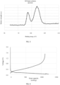
FIG. 1 is an X-ray powder diffraction (XRD) pattern of a negative electrode material according to Example 1 of the present disclosure. -
FIG. 2 is a total spectrum of X-ray photoelectron spectroscopy (XPS) of a negative electrode material according to Example 1 of the present disclosure. -
FIG. 3 is a high resolution spectrum of an X-ray photoelectron spectroscopy (XPS) of a negative electrode material in 90 eV to 110 eV according to Example 1 of the present disclosure. -
FIG. 4 is a curve of lithium intercalation and lithium deintercalation of a negative electrode material according to Example 1 of the present disclosure. - The present disclosure is further described in detail with reference to specific embodiments below. It should be understood that the following embodiments merely illustrate and explain an example of the present disclosure, and should not be construed as limiting the protection scope of the present disclosure. All technologies implemented based on the foregoing content of the present disclosure are within the protection scope of the present disclosure.
- An experimental method used in the following embodiments is a conventional method unless otherwise stated. A reagent, a material, and the like used in the following examples may be all obtained from a commercial channel unless otherwise stated.
- In the present disclosure, relative content of an element Si and an element C in a negative electrode material is tested by using an X-ray fluorescence (XRF) or energy dispersive spectroscopy (EDS) analysis method, for example, by using a Thermo Fisher X-ray fluorescence spectrometer or an Oxford energy dispersive spectrometer.
- In the present disclosure, an X-ray diffraction (XRD) method is used for a 2θ characteristic diffraction peak. For example, a Shimadzu XRD-6100 X-ray diffractometer is used to conduct a test. A sample quantity used in the test is 0.5 g/cm2, a Kα line of Cu is used as an incident X-ray, a working voltage of an X-ray source is 40 kV, a test power is 2 kW, a horizontal coordinate is 2θ in a unit of °, a vertical coordinate is signal strength, a test interval is 10° to 80°, a scanning rate is 4°/min, and a data sampling interval is 0.02°.
- In the present disclosure, a transmission electron microscope (TEM) analysis method, for example, a Japan Electron JEM-F200 field emission transmission electron microscope, is used to present a thickness of a shell layer.
- In the present disclosure, an X-ray photoelectron spectroscopy (XPS) analysis method, for example, a Thermo Fisher X-ray photoelectron spectrometer, is used to present a type and a content of an element in the shell layer. Peak division of a binding energy peak in a high resolution spectrum of an XPS may be performed by using Origin software (Version ≥ 8.0). A conventional Gaussian function is selected as a function type.
- In the present disclosure, a laser particle size test method is used for a median particle size Dv50 of the negative electrode material. For example, a Malvern particle size analyzer is used for measurement. Test steps are as follows: The negative electrode material is dispersed in deionized water containing a dispersing agent (for example, nonylphenol polyoxyethylene ether, where a content ranges from 0.02 wt% to 0.03 wt%) to form a mixture. Sonication is performed on the mixture for 2 minutes. Then, the mixture is put into the Malvern particle size analyzer for a test.
- In the present disclosure, a Brunauer-Emmett-Teller (BET) test method is used for a specific surface area and a pore volume of porous carbon. For example, a Tri Star II specific surface analyzer is used for measurement.
- In the present disclosure, commercialized porous carbon is a non-graphitizing porous carbon material purchased from Aladdin.
- Synthesis of a negative electrode material: 30g commercialized porous carbon (a BET specific surface area is 900 m2/g, and a pore volume is 0.5 cm3/g) was placed into a vapor deposition furnace. Mixed gas of high-purity argon and monosilane in a volume ratio of 9:1 was introduced at a flow rate of 300 sccm. Then, a temperature was raised to 475°C to crack the monosilane, and a total cracking duration was controlled to 10 h. Afterward, a sample was taken out, then placed into a muffle furnace, and heated at 120°C for 8 h, so that amorphous silicon on a surface of a particle was oxidized into silicon dioxide. In this way, the negative electrode material in Example 1 was obtained.
- Synthesis of a negative electrode material: 30g commercialized porous carbon (a BET specific surface area is 1300 m2/g, and a pore volume is 0.7 cm3/g) was placed into a vapor deposition furnace. Mixed gas of high-purity argon and monosilane in a volume ratio of 9:1 was introduced at a flow rate of 300 sccm. Then, a temperature was raised to 475°C to crack the monosilane, and a total cracking duration was controlled to 10 h. Afterward, a sample was taken out, then placed into a muffle furnace, and heated at 120°C for 8 h, so that amorphous silicon on a surface of a particle was oxidized into silicon dioxide. In this way, the negative electrode material in Example 2 was obtained.
- Synthesis of a negative electrode material: 30g commercialized porous carbon (a BET specific surface area is 1300 m2/g, and a pore volume is 0.7 cm3/g) was placed into a vapor deposition furnace. Mixed gas of high-purity argon and monosilane in a volume ratio of 4:1 was introduced at a flow rate of 300 sccm. Then, a temperature was raised to 475°C to crack the monosilane, and a total cracking duration was controlled to 10 h. Afterward, a sample was taken out, then placed into a muffle furnace, and heated at 120°C for 8 h, so that amorphous silicon on a surface of a particle was oxidized into silicon dioxide. In this way, the negative electrode material in Example 3 was obtained.
- Synthesis of a negative electrode material: 30g commercialized porous carbon (a BET specific surface area is 1300 m2/g, and a pore volume is 0.7 cm3/g) was placed into a vapor deposition furnace. Mixed gas of high-purity argon and silicoethane in a volume ratio of 4:1 was introduced at a flow rate of 300 sccm. Then, a temperature was raised to 475°C to crack the silicoethane, and a total cracking duration was controlled to 10 h. Afterward, a sample was taken out, then placed into a muffle furnace, and heated at 120°C for 8 h, so that amorphous silicon on a surface of a particle was oxidized into silicon dioxide. In this way, the negative electrode material in Example 4 was obtained.
- Synthesis of a negative electrode material: 30g commercialized porous carbon (a BET specific surface area is 1300 m2/g, and a pore volume is 0.7 cm3/g) was placed into a vapor deposition furnace. Mixed gas of high-purity argon and silicoethane in a volume ratio of 4:1 was introduced at a flow rate of 300 sccm. Then, a temperature was raised to 500°C to crack the silicoethane, and a total cracking duration was controlled to 10 h. Afterward, a sample was taken out, then placed into a muffle furnace, and heated at 120°C for 8 h, so that amorphous silicon on a surface of a particle was oxidized into silicon dioxide. In this way, the negative electrode material in Example 5 was obtained.
- Synthesis of a negative electrode material: 30g commercialized porous carbon (a BET specific surface area is 1300 m2/g, and a pore volume is 0.7 cm3/g) was placed into a vapor deposition furnace. Mixed gas of high-purity argon and silicoethane in a volume ratio of 4:1 was introduced at a flow rate of 300 sccm. Then, a temperature was raised to 500°C to crack the silicoethane, and a total cracking duration was controlled to 10 h. Afterward, a sample was taken out, then placed into a muffle furnace, and heated at 200°C for 8 h, so that amorphous silicon on a surface of a particle was oxidized into silicon dioxide. In this way, the negative electrode material in Example 6 was obtained.
- Synthesis of a negative electrode material: 30g commercialized porous carbon (a BET specific surface area is 1300 m2/g, and a pore volume is 0.7 cm3/g) was placed into a vapor deposition furnace. Mixed gas of high-purity argon and silicoethane in a volume ratio of 4:1 was introduced at a flow rate of 300 sccm. Then, a temperature was raised to 500°C to crack the silicoethane, and a total cracking duration was controlled to 10 h. Afterward, a sample was taken out, then placed into a muffle furnace, and heated at 200°C for 8 h, so that amorphous silicon on a surface of a particle was oxidized into silicon dioxide. The silicon dioxide was lithiated into lithium silicate by using a lithium biphenyl-tetrahydrofuran solution, washing was performed by using tetrahydrofuran, and then drying was performed. In this way, the negative electrode material in Example 7 was obtained.
- Synthesis of a negative electrode material: 30g commercialized porous carbon (a BET specific surface area is 1300 m2/g, and a pore volume is 0.7 cm3/g) was placed into a vapor deposition furnace. Mixed gas of high-purity argon and silicoethane in a volume ratio of 4:1 was introduced at a flow rate of 300 sccm. Then, a temperature was raised to 500°C to crack the silicoethane, and a total cracking duration was controlled to 10 h. Afterward, a sample was taken out, then placed into a muffle furnace, and heated at 50°C for 2 h, so that amorphous silicon on a surface of a particle was oxidized into a mixture of silicon monoxide and silicon dioxide. In this way, the negative electrode material in Example 8 was obtained.
- Synthesis of a negative electrode material: 30g commercialized porous carbon (a BET specific surface area is 900 m2/g, and a pore volume is 0.5 cm3/g) was placed into a vapor deposition furnace. Mixed gas of high-purity argon and monosilane in a volume ratio of 9:1 was introduced at a flow rate of 600 sccm. Then, a temperature was raised to 475°C to crack the monosilane, and a total cracking duration was controlled to 24 h. Afterward, a sample was taken out, then placed into a muffle furnace, and heated at 120°C for 8 h, so that amorphous silicon on a surface of a particle was oxidized into silicon dioxide. In this way, the negative electrode material in Example 9 was obtained.
- Synthesis of a negative electrode material: Commercialized bitumen powder (a softening point is 200°C) was dissolved in toluene. Bitumen and nano-silicon were added in a mass ratio of 1:1 into commercialized nano-silicon (a median particle size Dv50 is 50 nm). Then, spraying and drying were performed to remove a toluene solvent, to obtain a silicon material coated with bitumen. Afterward, the silicon material coated with bitumen was placed into a tube furnace to be carbonized at a high temperature of 800°C in an argon atmosphere. In this way, a silicon-carbon composite material in Comparative Example 1 was obtained.
- Synthesis of a negative electrode material: A specific quantity of artificial graphite (a BET specific surface area is 2 m2/g) was placed into a vapor deposition furnace. Mixed gas of high-purity argon and monosilane in a ratio of 9:1 was introduced at a flow rate of 300 sccm. Then, a temperature was raised to 475°C to crack the monosilane, and a total cracking duration was controlled to 10 h. Afterward, a sample was taken out, then placed into a muffle furnace, and heated at 120°C for 8 h, so that amorphous silicon on a surface of a particle was oxidized into silicon dioxide. In this way, the negative electrode material in Comparative Example 2 was obtained.
- Synthesis of a negative electrode material: 30g commercialized porous carbon (a BET specific surface area is 900 m2/g, and a pore volume is 0.5 cm3/g) was placed into a vapor deposition furnace. Mixed gas of high-purity argon and monosilane in a volume ratio of 9:1 was introduced at a flow rate of 300 sccm. Then, a temperature was raised to 475°C to crack the monosilane, and a total cracking duration was controlled to 10 h. Afterward, a sample was taken out. In this way, the negative electrode material in Comparative Example 3 was obtained.
- Synthesis of a negative electrode material: 30g commercialized porous carbon (a BET specific surface area is 900 m2/g, and a pore volume is 0.5 cm3/g) was placed into a vapor deposition furnace. Mixed gas of high-purity argon and monosilane in a volume ratio of 9:1 was introduced at a flow rate of 300 sccm. Then, a temperature was raised to 475°C to crack the monosilane, and a total cracking duration was controlled to 10 h. Afterward, a sample was taken out, placed into a tube furnace in an argon atmosphere, and heated at 700°C for 8 h. In this way, the negative electrode material in Comparative Example 4 was obtained.
- Synthesis of a negative electrode material: 30g commercialized porous carbon (a BET specific surface area is 900 m2/g, and a pore volume is 0.5 cm3/g) was placed into a vapor deposition furnace. Mixed gas of high-purity argon and monosilane in a volume ratio of 9:1 was introduced at a flow rate of 300 sccm. Then, a temperature was raised to 475°C to crack the monosilane, and a total cracking duration was controlled to 10 h. Afterward, a sample was taken out, placed into a tube furnace in an argon atmosphere, heated at 700°C for 8 h, placed into a muffle furnace, and heated at 120°C for 8 h. In this way, the negative electrode material in Comparative Example 5 was obtained.
- In the negative electrode materials prepared in the foregoing examples and the comparative examples, the negative electrode material corresponds to a diffraction peak 1 in a range of 2θ = 23.0° ± 0.5° in an X-ray powder diffraction (XRD) test, and a ratio of a peak height value to a peak width value of the diffraction peak 1 is x1; and the negative electrode material corresponds to a diffraction peak 2 in a range of 2θ = 28.4° ± 0.5°, and a ratio of a peak height value to a peak width value of the diffraction peak 2 is x2. The negative electrode material corresponds to a binding energy peak in a high resolution spectrum in a range of 90 eV to 110 eV in an X-ray photoelectron spectroscopy (XPS) test. The binding energy peak is divided into a binding energy peak 1 in 97 eV to 100 eV and a binding energy peak 2 in 101 eV to 104 eV by using peak division software. An area of the binding energy peak 1 is y1. An area of the binding energy peak 2 is y2. In the negative electrode material, a mass content of a carbon element is a, and a mass content of a silicon element is b. Test results are shown in Table 1.
Table 1 Performance test results of the negative electrode materials in examples and comparative examples x1 x2 y1/y2 a b a + b Example 1 71 35 0.33 51% 44% 95% Example 2 66 39 0.41 48% 47% 95% Example 3 61 40 0.42 47% 49% 96% Example 4 60 38 0.40 48% 49% 97% Example 5 61 39 0.41 48% 50% 98% Example 6 58 28 0.26 45% 47% 92% Example 7 56 25 0.22 44% 46% 90% Example 8 57 72 0.99 46% 47% 93% Example 9 23 23.3 1.01 13% 76% 89% Comparative Example 1 17 15000 12.0 35% 60% 95% Comparative Example 2 800 10 6.10 74% 20% 94% Comparative Example 3 60 41 16.0 49% 51% 100% Comparative Example 4 67 1500 19.0 49% 51% 100% Comparative Example 5 66 1400 0.37 48% 50% 98% - It can be learned from Table 1 that, for the negative electrode materials prepared in Examples 1 to 9, in the X-ray powder diffraction (XRD) test, a ratio of a peak height value to a peak width value of the diffraction peak 1 in the range of 2θ = 23.0° ± 0.5° is x1, and a ratio of a peak height value to a peak width value of the diffraction peak 2 in the range of 2θ = 28.4° ± 0.5° is x2, where x1 and x2 meet that 0 < x1 ≤ 200 and 0 < x2 ≤ 500. For the negative electrode materials prepared in Examples 1 to 9, in the X-ray photoelectron spectroscopy (XPS) test, the binding energy peak in the high resolution spectrum in a range of 90 eV to 110 eV is divided into the binding energy peak 1 in 97 eV to 100 eV and the binding energy peak 2 in 101 eV to 104 eV by using Origin software, where the area y1 of the binding energy peak 1 and the area y2 of the binding energy peak 2 meet that 0 ≤ y1/y2 ≤ 10.
- The foregoing results indicate that a core of the negative electrode material in Examples 1 to 8 includes a non-graphitizing porous carbon material and amorphous silicon, and a surface of the core includes a shell layer of a silicon-containing compound in which a silicon valence is greater than zero. In addition, in the negative electrode material that meets the foregoing conditions, a content a of a carbon element and a content b of a silicon element meet that 25% ≤ a < 100%, 0 < b ≤ 75%, and 90% ≤ a + b < 100%, to ensure that the negative electrode material has a relatively small impurity content.
- In the negative electrode materials prepared in Comparative Examples 1, 4, and 5, x2 does not meet that 0 < x2 ≤ 500, which indicates that crystallization of silicon in the negative electrode material is strong. In the negative electrode material prepared in Comparative Example 2, x1 does not meet that 0 < x1 ≤ 200, which indicates that the carbon material in the negative electrode material has a high degree of graphitization and a structure is regular. In the negative electrode materials prepared in Comparative Examples 1, 3, and 4, y1 and y2 do not meet that 0 ≤ y1/y2 ≤ 10. In addition, the content a of the carbon element and the content b of the silicon element in the negative electrode materials prepared in Comparative Examples 1 to 5 also meet that 25% ≤ a < 100%, 0 < b ≤ 75%, and 90% ≤ a + b < 100%, which indicates that the contents of the main elements in the negative electrode material are close to those in Examples 1 to 8. In the negative electrode material prepared in Example 9, the content a of the carbon element and the content b of the silicon element do not meet that 25% ≤ a < 100%, 0 < b ≤ 75%, and 90% ≤ a + b < 100%, which indicates that a content of an impurity element in the negative electrode material is large.
- The negative electrode materials in the foregoing examples and comparative examples are assembled into button-type half batteries for a test. A specific manufacturing method is as follows:
(1) The negative electrode material prepared above, artificial graphite, sodium carboxymethyl cellulose, styrene-butadiene rubber, and Super P were mixed in a mass ratio of 50:46.5:1.6:1.6:0.3, deionized water was added, and mixing was evenly performed by using a vacuum mixer, to obtain a negative electrode slurry.
(2) Copper foil was coated with the negative electrode slurry in step (1), and the negative electrode slurry on the copper foil was dried in an oven at 80°C and then transferred to a vacuum oven at 100°C for 12 h, to obtain a negative electrode plate with a surface density of about 6.0 mg/cm2.
(3) In a dry environment, the negative electrode plate in step (2) was rolled and compacted at about 1.3 g/cm3, and then a round negative electrode plate with a diameter of 12 mm was manufactured by using a sheet-punching machine.
(4) In a glove box, the round negative electrode plate in step (3) was used as a working electrode, a metal lithium plate was used as a counter electrode, a polyethylene separator with a thickness of 20 µm was used as a separator, and an electrolyte solution was added, to obtain a button-type half battery through assembling. Performance of the button-type half battery was tested by using a land (LAND) test system. A test temperature was 25°C. Details are as follows:
Lithium intercalation was performed at a current of 0.1 mA to 0.005 V, and the button-type half battery was set aside for 10 min. Lithium intercalation was performed at a current of 0.05 mA to 0.005 V, and the button-type half battery was set aside for 10 min. Then, lithium deintercalation was performed at a current of 0.1 mA to 1.5 V. An initial lithium intercalation capacity and an initial lithium deintercalation capacity were obtained. The initial lithium deintercalation capacity was divided by a mass of the negative electrode material in the foregoing round negative electrode plate to obtain a capacity per gram of the negative electrode material. The initial lithium deintercalation capacity was divided by the initial lithium intercalation capacity to obtain an initial Coulombic efficiency of the negative electrode material. Test results are shown in Table 2.Table 2 Performance test results of button-type half batteries in examples and comparative examples Capacity per gram(mAh/g) Initial Coulombic efficiency Example 1 1125.2 90.44% Example 2 1137.6 90.71% Example 3 1153.3 90.92% Example 4 1168.1 90.92% Example 5 1204.2 91.11% Example 6 1140.5 89.04% Example 7 1133.2 92.63% Example 8 1149.4 90.21% Example 9 1539.8 91.38% Comparative Example 1 1394.6 83.52% Comparative Example 2 789.9 89.41% Comparative Example 3 1188.4 92.02% Comparative Example 4 879.5 81.65% Comparative Example 5 812.7 79.39% - It can be learned from Table 2 that the capacities per gram of the button-type half batteries prepared in Examples 1 to 8 each range from 1120 mAh/g to 1210 mAh/g, and the initial Coulombic efficiencies each are above 89%. A difference is not large. The button-type half battery prepared in Example 9 has a relatively high capacity per gram and initial Coulombic efficiency because of a relatively high content of silicon in the button-type half battery. The capacities per gram and the initial Coulombic efficiencies of the button-type half batteries prepared in Comparative Examples 1 to 5 are greatly different. The button-type half battery prepared by using a conventional pyrolytic carbon-encapsulated silicon material in Comparative Example 1 has a relatively high capacity per gram and a relatively low initial Coulombic efficiency. The capacity per gram of the button-type half battery prepared in Comparative Example 2 is relatively low. This is because when a graphitizing carbon material is used as a carbon material of a core, the core does not have enough space to accommodate silicon. Consequently, a lithium storage capacity of the prepared negative electrode material is limited. The capacity per gram and the initial Coulombic efficiency of the button-type half battery prepared in Comparative Example 3 are similar to those of the examples. The capacities per gram and the initial Coulombic efficiencies of the button-type half batteries prepared in Comparative Examples 4 and 5 are relatively low. This is because silicon is crystallized in porous carbon to block pores of carbon, resulting in a large decrease in lithium intercalation kinetics of the negative electrode material and a large decrease in lithium storage performance of the negative electrode material.
- The materials in the foregoing examples and comparative examples are assembled into batteries. A specific manufacturing method is as follows:
(1) The negative electrode material prepared above, artificial graphite, sodium carboxymethyl cellulose, styrene-butadiene rubber, and Super P were mixed in a mass ratio of 50:46.5:1.6:1.6:0.3, and deionized water was added, to obtain a negative electrode slurry by using a vacuum mixer. Copper foil with a thickness of 8 µm was evenly coated with the negative electrode slurry. A surface density of the negative electrode slurry coated on a surface of a negative electrode current collector is 11.0 mg/cm2. The copper foil coated with the negative electrode slurry was transferred to an oven at 80°C for drying for 12 h. Then rolling and cutting were performed to obtain a negative electrode plate.
(2) Lithium cobalt oxide (LCO), polyvinylidene fluoride (PVDF), acetylene black, and carbon nanotubes (CNTs) were mixed in a mass ratio of 96:2:1.5:0.5, N-methylpyrrolidone was added, and stirring was performed by using a vacuum mixer until a mixture was mixed evenly, to obtain a positive electrode slurry. Aluminum foil with a thickness of 12 µm was evenly coated with the positive electrode slurry. The aluminum foil coated with the positive electrode slurry was baked in an oven, transferred to an oven at 120°C for drying for 8 h, and then rolled and cut to obtain a needed positive electrode plate. A size of the positive electrode plate is smaller than that of a negative electrode plate. A reversible capacity of a unit area of the positive electrode plate is 4% lower than that of the negative electrode plate.
(3) A polyethylene separator with a thickness of 8 µm was selected.
(4) The positive electrode plate prepared above, the separator, and the negative electrode plate were stacked in an order, to ensure that the separator separates the positive electrode plate from the negative electrode plate. Then, a bare cell was obtained through winding. The bare cell was placed into an aluminum-plastic film shell. An electrolyte solution was injected into the dried bare cell. Processes such as vacuum encapsulation, setting aside, forming, shaping, and sorting were executed, to obtain a needed battery. A land (LAND) test system was used to test performance of the batteries. A test temperature was 25°C. Details are as follows:
(4-1) The battery was charged at a constant current of 0.7 C to 4.45 V, charged at a constant voltage to 0.05 C, and set aside for 10 minutes. The battery was discharged at 0.2 C to 3.0 V, to obtain a discharge capacity. The discharge capacity was used as a nominal capacity. The nominal capacity was multiplied by an average discharge voltage to obtain battery energy. The battery energy was divided by a battery volume to obtain a battery energy density. Test results are shown in Table 3.
(4-2) The battery was charged at a constant current of 0.7 C to 3.85 V, and charged at a constant voltage to 0.01 C. A battery thickness was measured in this time, and was used as an initial battery thickness. The battery was charged at a constant current of 1.5 C to 4.45 V, charged at a constant voltage to 0.05 C, and set aside for 10 min. The battery was discharged at 1 C to 3.0 V and set aside for 10 min. The charging and discharging steps were performed as a cycle. A maximum value of discharge capacities in first three cycles was used as an initial battery capacity. A ratio of a capacity after 500 cycles to the initial capacity was a capacity retention rate of the battery. A thickness of the battery after 500 cycles was measured. A difference between the thickness and the initial thickness was divided by the initial thickness to obtain a volume expansion rate of the battery. Test results are shown in Table 3.Table 3 Performance test results of batteries in examples and comparative examples Nominal capacity mAh Energy density Wh/L Capacity retention rate after 500 cycles Volume expansion rate after 500 cycles Example 1 3521 817 90.64% 8.03% Example 2 3537 818 90.49% 8.31% Example 3 3554 820 90.13% 8.08% Example 4 3568 825 90.06% 8.06% Example 5 3591 833 90.96% 8.22% Example 6 3546 828 90.37% 8.42% Example 7 3533 827 90.42% 8.17% Example 8 3558 830 90.50% 8.21% Example 9 3646 839 25.90% 22.14% Comparative Example 1 3605 837 55.49% 16.91% Comparative Example 2 3323 749 60.77% 15.88% Comparative Example 3 3573 819 65.19% 15.66% Comparative Example 4 3568 755 43.17% 18.73% Comparative Example 5 3552 749 45.01% 18.45% - It can be learned from Table 3 that the nominal capacities of the batteries in Examples 1 to 8 are all within a range of 3520 mAh to 3600 mAh, and energy densities are all within a range of 815 Wh/L to 835 Wh/L. A difference is not large. The nominal capacities and the energy densities in Comparative Examples 1 to 5 fluctuate greatly according to different structural features. Rules and reasons thereof are similar to those described in Table 2. After 500 cycles, the capacity retention rates of the batteries in Examples 1 to 8 each range from 90% to 91%, and the batteries present good cycling stability performance. However, the capacity retention rates of the batteries in Comparative Examples 1 to 5 are low, and the batteries present poor stability. In addition, after 500 cycles, the volume expansion rates of the batteries in Examples 1 to 8 each range from 8.0% to 8.5%, and the volume expansion rates of the batteries in Comparative Examples 1 to 5 each are greater than 15% that is obviously higher than an average level of the examples.
- The foregoing describes the implementations of the present disclosure. However, the present disclosure is not limited to the foregoing implementations. Any modification, equivalent replacement, improvement, or the like made without departing from the spirit and the principle of the present disclosure shall fall within the protection scope of the present disclosure.
Claims (15)
- A negative electrode material, wherein the negative electrode material has a core-shell structure, the core-shell structure comprises a shell layer and a core, the shell layer comprises at least one of silicon monoxide, silicon dioxide, or lithium silicate, the core comprises a carbon material and a silicon material, the carbon material comprises a non-graphitizing porous carbon material, and the silicon material comprises amorphous silicon.
- The negative electrode material according to claim 1, wherein the carbon material is a non-graphitizing porous carbon material, and the silicon material is amorphous silicon; and
preferably, a coverage rate of the shell layer on a surface of the core ranges from 33% to 100%. - The negative electrode material according to claim 1 or 2, wherein a thickness of the shell layer is less than or equal to 10 nm; and
preferably, the thickness of the shell layer ranges from 0.01 nm to 10 nm. - The negative electrode material according to any one of claims 1 to 3, wherein a median particle size Dv50 of the amorphous silicon ranges from 0.5 nm to 15 µm; and/or
the non-graphitizing porous carbon material is non-graphitizing porous hard carbon. - The negative electrode material according to any one of claims 1 to 4, wherein a specific surface area BET of the non-graphitizing porous carbon material ranges from 200 m2/g to 2000 m2/g; and
preferably, the specific surface area BET of the non-graphitizing porous carbon material ranges from 900 m2/g to 1300 m2/g. - The negative electrode material according to any one of claims 1 to 5, wherein a pore volume of the non-graphitizing porous carbon material ranges from 0.2 cm3/g to 1.2 cm3/g;preferably, the pore volume of the non-graphitizing porous carbon material ranges from 0.5 cm3/g to 0.7 cm3/g; and/ora pore diameter of the non-graphitizing porous carbon material ranges from 0.5 nm to 100 nm.
- The negative electrode material according to any one of claims 1 to 6, wherein the negative electrode material corresponds to a diffraction peak 1 in a range of 2θ = 23.0° ± 0.5° in an X-ray powder diffraction test, and a ratio x1 of a peak height value to a peak width value of the diffraction peak 1 meets that 0 < x1 ≤ 200; and the negative electrode material corresponds to a diffraction peak 2 in a range of 2θ = 28.4° ± 0.5°, and a ratio x2 of a peak height value to a peak width value of the diffraction peak 2 meets that 0 < x2 ≤ 500; and
preferably, 0 < x1 ≤ 100, and 0 < x2 ≤ 100. - The negative electrode material according to any one of claims 1 to 7, wherein the negative electrode material corresponds to a binding energy peak in a range of a total spectrum of 96 eV to 105 eV in an X-ray photoelectron spectroscopy test, and the binding energy peak in a high resolution spectrum in a range of 90 eV to 110 eV may be divided at least into a binding energy peak 1 whose area is y1 in 97 eV to 100 eV and a binding energy peak 2 whose area is y2 in 101 eV to 104 eV, wherein y1 and y2 meet that 0 ≤ y1/y2 ≤ 10; and
preferably, 0.2 ≤ y1/y2 ≤ 5. - The negative electrode material according to any one of claims 1 to 8, wherein in the negative electrode material, a mass content a of a carbon element meets that 25% ≤ a < 100%, a mass content b of a silicon element meets that 0 < b < 75%, and 90% ≤ a + b < 100%; and
preferably, 25% <_ a <_ 95%, and 5% < b < 75%. - The negative electrode material according to any one of claims 1 to 9, wherein a specific surface area BET of the negative electrode material ranges from 0.5 m2/g to 20 m2/g; and/or
a median particle size Dv50 of the negative electrode material ranges from 1 µm to 20 µm. - A negative electrode plate, wherein the negative electrode plate comprises the negative electrode material according to any one of claims 1 to 10.
- The negative electrode plate according to claim 11, wherein the negative electrode plate comprises a negative electrode current collector and a negative electrode active material layer on at least one side surface of the negative electrode current collector, and the negative electrode active material layer comprises the negative electrode material according to any one of claims 1 to 10.
- The negative electrode plate according to claim 11 or 12, wherein the negative electrode active material layer further comprises at least one of graphite, hard carbon, or soft carbon; andpreferably, the graphite comprises any one of artificial graphite or natural graphite; and/orthe negative electrode active material layer further comprises a conductive agent; andpreferably, the conductive agent is selected from one or more of carbon black, acetylene black, Ketjen black, a carbon fiber, a single-walled carbon nanotube, and a multi-walled carbon nanotube.
- The negative electrode plate according to any one of claims 11 to 13, wherein the negative electrode active material layer further comprises a binder; and
preferably, the binder is selected from one or more of carboxymethyl cellulose, sodium carboxymethyl cellulose, lithium carboxymethyl cellulose, hydroxypropyl cellulose, cellulose acetate, polyethylene, poly(vinyl alcohol), polyvinyl chloride, polyvinyl fluoride, polyvinylpyrrolidone, polytetrafluoroethylene, polypropylene, styrene-butadiene rubber, and epoxy resin. - A battery, wherein the battery comprises the negative electrode material according to any one of claims 1 to 10 and/or the negative electrode plate according to any one of claims 11 to 14.
Applications Claiming Priority (2)
| Application Number | Priority Date | Filing Date | Title |
|---|---|---|---|
| CN202210665824.5A CN114864909A (en) | 2022-06-13 | 2022-06-13 | Negative electrode material, negative plate comprising negative electrode material and battery |
| PCT/CN2023/082513 WO2023241148A1 (en) | 2022-06-13 | 2023-03-20 | Negative electrode material, and negative electrode sheet and battery comprising same |
Publications (2)
| Publication Number | Publication Date |
|---|---|
| EP4485570A1 true EP4485570A1 (en) | 2025-01-01 |
| EP4485570A4 EP4485570A4 (en) | 2025-10-15 |
Family
ID=82623762
Family Applications (1)
| Application Number | Title | Priority Date | Filing Date |
|---|---|---|---|
| EP23822720.1A Pending EP4485570A4 (en) | 2022-06-13 | 2023-03-20 | NEGATIVE ELECTRODE MATERIAL AND NEGATIVE ELECTRODE FOIL AND BATTERY THEREOF |
Country Status (4)
| Country | Link |
|---|---|
| US (1) | US20250023028A1 (en) |
| EP (1) | EP4485570A4 (en) |
| CN (1) | CN114864909A (en) |
| WO (1) | WO2023241148A1 (en) |
Families Citing this family (21)
| Publication number | Priority date | Publication date | Assignee | Title |
|---|---|---|---|---|
| CN114864909A (en) * | 2022-06-13 | 2022-08-05 | 珠海冠宇电池股份有限公司 | Negative electrode material, negative plate comprising negative electrode material and battery |
| CN115642234A (en) * | 2022-09-30 | 2023-01-24 | 北京卫蓝新能源科技有限公司 | Silicon-carbon negative electrode material with pore gradient structure, preparation method thereof and lithium ion battery |
| CN115332532B (en) * | 2022-10-12 | 2023-04-07 | 宁德新能源科技有限公司 | Hard carbon material and preparation method thereof |
| CN116053434B (en) * | 2022-12-30 | 2025-08-26 | 宁德新能源科技有限公司 | Negative electrode material, secondary battery and electronic device |
| CN116470015A (en) * | 2023-03-04 | 2023-07-21 | 珠海冠宇电池股份有限公司 | A kind of negative electrode material, negative electrode sheet and battery |
| CN116598452B (en) * | 2023-05-15 | 2024-03-12 | 江门市和创新能源材料有限公司 | A kind of silicon carbon negative electrode material and its preparation method and application |
| CN116364860B (en) * | 2023-06-01 | 2023-11-10 | 宁德时代新能源科技股份有限公司 | Secondary battery, method for manufacturing the same, and power consumption device |
| CN119230830A (en) * | 2023-06-30 | 2024-12-31 | 宁德时代新能源科技股份有限公司 | Negative electrode sheet, battery cell, battery and electrical device |
| CN116613299B (en) * | 2023-07-17 | 2023-11-24 | 浙江锂宸新材料科技有限公司 | Preparation method of silicon-carbon anode material and product thereof |
| CN117059765B (en) * | 2023-08-04 | 2024-06-07 | 江门市和创新能源材料有限公司 | Silicon-carbon composite material and preparation method and application thereof |
| CN117727930B (en) * | 2023-11-29 | 2025-08-26 | 贝特瑞新材料集团股份有限公司 | Negative electrode material and preparation method thereof, negative electrode sheet and battery |
| JP2025091252A (en) * | 2023-12-06 | 2025-06-18 | 信越化学工業株式会社 | Negative electrode active material and method for producing same |
| JP2025092126A (en) * | 2023-12-08 | 2025-06-19 | 信越化学工業株式会社 | Negative electrode active material and method for producing same |
| WO2025126709A1 (en) * | 2023-12-13 | 2025-06-19 | 信越化学工業株式会社 | Negative electrode active material and method for manufacturing same |
| WO2025126987A1 (en) * | 2023-12-13 | 2025-06-19 | 信越化学工業株式会社 | Negative electrode active material and method for manufacturing same |
| JP2025102565A (en) * | 2023-12-26 | 2025-07-08 | 信越化学工業株式会社 | Apparatus for manufacturing negative electrode active material and method for manufacturing negative electrode active material |
| CN117699772B (en) * | 2024-02-02 | 2024-08-16 | 中国石油大学(华东) | Preparation method and application of silane-deposited porous carbon negative electrode material |
| JP2025125256A (en) * | 2024-02-15 | 2025-08-27 | 信越化学工業株式会社 | Negative electrode active material and method for producing the same |
| CN119725498A (en) * | 2025-01-03 | 2025-03-28 | 安徽得壹能源科技有限公司 | Silicon-carbon negative electrode material, preparation method thereof and battery |
| CN119674049B (en) * | 2025-02-24 | 2025-04-15 | 浙江格源新材料科技有限公司 | Preparation method of silicon-carbon anode material for reducing interface side reaction |
| CN120117591B (en) * | 2025-05-14 | 2025-07-11 | 浙江格源新材料科技有限公司 | Preparation method of multi-order ordered silicon-carbon anode material |
Family Cites Families (24)
| Publication number | Priority date | Publication date | Assignee | Title |
|---|---|---|---|---|
| CN103840140B (en) * | 2012-11-21 | 2017-12-26 | 清华大学 | porous carbon-silicon composite material and preparation method thereof |
| JP5956690B2 (en) * | 2014-04-16 | 2016-07-27 | 昭和電工株式会社 | Negative electrode material for lithium ion battery and its use |
| CN103956496A (en) * | 2014-04-29 | 2014-07-30 | 长沙格翎电池材料有限公司 | Lithium ion battery negative active material and preparation method thereof |
| WO2016137024A1 (en) * | 2015-02-24 | 2016-09-01 | (주)오렌지파워 | Silicon anode active material and preparation method therefor |
| KR102003298B1 (en) * | 2015-09-11 | 2019-07-24 | 주식회사 엘지화학 | Core-shell silicon composite, method for preparaing the same, and negative electrode active material for rechargeable lithium battery comprising the same |
| CN106025237B (en) * | 2016-07-21 | 2018-09-25 | 中国科学院山西煤炭化学研究所 | Silicon based composite material and preparation method thereof is covered in double-contracting |
| KR20190074313A (en) * | 2016-11-11 | 2019-06-27 | 쇼와 덴코 가부시키가이샤 | Negative electrode material and lithium ion battery |
| US10804530B2 (en) * | 2017-08-03 | 2020-10-13 | Nanograf Corporation | Composite anode material including surface-stabilized active material particles and methods of making same |
| CN107887587A (en) * | 2017-11-09 | 2018-04-06 | 中南大学 | Composite cathode material for lithium ion cell and preparation method thereof |
| WO2019131860A1 (en) * | 2017-12-28 | 2019-07-04 | 昭和電工株式会社 | Negative electrode material for lithium ion secondary battery |
| CN109119618A (en) * | 2018-08-30 | 2019-01-01 | 马鞍山科达普锐能源科技有限公司 | A kind of nucleocapsid negative electrode material of lithium ion battery double-coating and preparation method thereof |
| TWI711208B (en) * | 2018-11-16 | 2020-11-21 | 國家中山科學研究院 | Negative electrode material of silicon oxide and amorphous carbon layer coated with nanosilicon with multilayer graphene as carrier and preparation method thereof |
| KR102691451B1 (en) * | 2018-12-13 | 2024-08-05 | 삼성전자주식회사 | Negative active material, lithium secondary battery including the material, and method for manufacturing the material |
| CN109599551B (en) * | 2018-12-28 | 2021-08-24 | 安普瑞斯(南京)有限公司 | A kind of doped multi-layer core-shell silicon-based composite material for lithium ion battery and preparation method thereof |
| US11374218B2 (en) * | 2019-08-21 | 2022-06-28 | GM Global Technology Operations LLC | Multilayer siloxane coatings for silicon negative electrode materials for lithium ion batteries |
| CN111430677B (en) * | 2019-09-30 | 2022-05-24 | 蜂巢能源科技有限公司 | Anode material and preparation method thereof, anode and lithium ion battery |
| KR102433749B1 (en) * | 2020-06-04 | 2022-08-19 | 주식회사 한솔케미칼 | Negative active material for lithium secondary battery, preparing method for the same and lithium secondary battery comprising the same |
| CN112054171A (en) * | 2020-08-13 | 2020-12-08 | 利普同呈(江苏)新能源科技有限公司 | Carbon-silicon negative electrode material and preparation method thereof |
| CN114284494B (en) * | 2020-09-27 | 2024-04-09 | 华为技术有限公司 | Nano silicon composite material and preparation method thereof, electrode material and battery |
| KR20220067261A (en) * | 2020-11-17 | 2022-05-24 | 삼성에스디아이 주식회사 | Negative active material for rechargeable lithium battery and rechargeable lithium battery including same |
| CN112447956B (en) * | 2020-11-27 | 2022-07-22 | 深圳市德方纳米科技股份有限公司 | Composite silicon-based negative electrode material, preparation method thereof and lithium ion battery |
| CN112563501A (en) * | 2020-12-07 | 2021-03-26 | 广东凯金新能源科技股份有限公司 | Pomegranate-like structure silicon-based composite material, and preparation method and application thereof |
| CN121011629A (en) * | 2021-12-31 | 2025-11-25 | 东莞新能源科技有限公司 | An electrochemical device and an electronic device |
| CN114864909A (en) * | 2022-06-13 | 2022-08-05 | 珠海冠宇电池股份有限公司 | Negative electrode material, negative plate comprising negative electrode material and battery |
-
2022
- 2022-06-13 CN CN202210665824.5A patent/CN114864909A/en active Pending
-
2023
- 2023-03-20 WO PCT/CN2023/082513 patent/WO2023241148A1/en not_active Ceased
- 2023-03-20 EP EP23822720.1A patent/EP4485570A4/en active Pending
-
2024
- 2024-09-26 US US18/898,600 patent/US20250023028A1/en active Pending
Also Published As
| Publication number | Publication date |
|---|---|
| US20250023028A1 (en) | 2025-01-16 |
| EP4485570A4 (en) | 2025-10-15 |
| CN114864909A (en) | 2022-08-05 |
| WO2023241148A1 (en) | 2023-12-21 |
Similar Documents
| Publication | Publication Date | Title |
|---|---|---|
| EP4485570A1 (en) | Negative electrode material, and negative electrode sheet and battery comprising same | |
| US20250333311A1 (en) | Negative electrode material, negative electrode plate, and battery | |
| US11901540B2 (en) | Composite anode active material, method of preparing the same, and lithium secondary battery including anode including composite anode active material | |
| KR101368474B1 (en) | Negative active material for rechargeable lithium battery, method of preparing the same, and rechargeable lithium battery including the same | |
| CN104380507B (en) | Negative electrode active material, lithium secondary battery comprising same, and method of manufacturing negative electrode active material | |
| JP2024164132A (en) | Negative electrode active material, method for producing the same, secondary battery, battery module including secondary battery, battery pack, and device | |
| US20190379044A1 (en) | Nickel active material precursor for lithium secondary battery, method for producing nickel active material precursor, nickel active material for lithium secondary battery produced by method, and lithium secondary battery having cathode containing nickel active material | |
| CN111525121A (en) | Silicon anode material with villus structure and preparation method thereof | |
| US20250286050A1 (en) | Negative electrode material, negative electrode plate, and battery | |
| CN1794494A (en) | Negative electrode active material for nonaqueous electrolyte secondary battery and nonaqueous electrolyte secondary battery | |
| KR20140070227A (en) | Negative active material for rechargeable lithium battery, method of preparing the same, and negative electrode and rechargeable lithium battery including the same | |
| KR101763478B1 (en) | Negative electrode active material for lithium secondary battery, method for preparing the same, and lithium secondary battery comprising the same | |
| CA2821882A1 (en) | Electrode material and method for producing the same | |
| CN114497489B (en) | Composite material, negative electrode sheet and battery comprising the composite material | |
| CN113594436A (en) | Negative electrode material, preparation method thereof and lithium ion battery comprising negative electrode material | |
| CN103339764A (en) | Method for preparing negative electrode active material | |
| KR20240078605A (en) | Composite particles, negative electrode active materials, and lithium ion secondary batteries | |
| CN114142015B (en) | A negative electrode material and a battery comprising the negative electrode material | |
| CN114464804B (en) | A negative electrode material and a lithium ion battery containing the negative electrode material | |
| KR20150021406A (en) | Negative active material for rechargeable lithium battery, method of preparing the same, and rechargeable lithium battery including the same | |
| WO2024166478A1 (en) | Negative electrode for lithium-ion battery, method for manufacturing negative electrode material, and method for identifying same | |
| KR102859928B1 (en) | Anode electrode for lithium secondary batteries and manufacturing method thereof | |
| CN120015898B (en) | Lithium ion secondary battery | |
| KR102887417B1 (en) | Anode for lithium secondary batteries and manufacturing method thereof | |
| EP4679525A1 (en) | Negative electrode active material, negative electrode sheet, battery, and electric device |
Legal Events
| Date | Code | Title | Description |
|---|---|---|---|
| STAA | Information on the status of an ep patent application or granted ep patent |
Free format text: STATUS: THE INTERNATIONAL PUBLICATION HAS BEEN MADE |
|
| PUAI | Public reference made under article 153(3) epc to a published international application that has entered the european phase |
Free format text: ORIGINAL CODE: 0009012 |
|
| STAA | Information on the status of an ep patent application or granted ep patent |
Free format text: STATUS: REQUEST FOR EXAMINATION WAS MADE |
|
| 17P | Request for examination filed |
Effective date: 20240923 |
|
| AK | Designated contracting states |
Kind code of ref document: A1 Designated state(s): AL AT BE BG CH CY CZ DE DK EE ES FI FR GB GR HR HU IE IS IT LI LT LU LV MC ME MK MT NL NO PL PT RO RS SE SI SK SM TR |
|
| DAV | Request for validation of the european patent (deleted) | ||
| DAX | Request for extension of the european patent (deleted) | ||
| A4 | Supplementary search report drawn up and despatched |
Effective date: 20250915 |
|
| RIC1 | Information provided on ipc code assigned before grant |
Ipc: H01M 4/36 20060101AFI20250909BHEP Ipc: H01M 4/38 20060101ALI20250909BHEP Ipc: H01M 4/62 20060101ALI20250909BHEP Ipc: H01M 10/0525 20100101ALI20250909BHEP Ipc: H01M 4/134 20100101ALI20250909BHEP |