EP4485554A1 - Electrode cutting device and method - Google Patents
Electrode cutting device and method Download PDFInfo
- Publication number
- EP4485554A1 EP4485554A1 EP23756699.7A EP23756699A EP4485554A1 EP 4485554 A1 EP4485554 A1 EP 4485554A1 EP 23756699 A EP23756699 A EP 23756699A EP 4485554 A1 EP4485554 A1 EP 4485554A1
- Authority
- EP
- European Patent Office
- Prior art keywords
- gripper
- area
- electrode
- electrode sheet
- disposed
- Prior art date
- Legal status (The legal status is an assumption and is not a legal conclusion. Google has not performed a legal analysis and makes no representation as to the accuracy of the status listed.)
- Pending
Links
Images



Classifications
-
- H—ELECTRICITY
- H01—ELECTRIC ELEMENTS
- H01M—PROCESSES OR MEANS, e.g. BATTERIES, FOR THE DIRECT CONVERSION OF CHEMICAL ENERGY INTO ELECTRICAL ENERGY
- H01M10/00—Secondary cells; Manufacture thereof
- H01M10/04—Construction or manufacture in general
- H01M10/0404—Machines for assembling batteries
-
- B—PERFORMING OPERATIONS; TRANSPORTING
- B26—HAND CUTTING TOOLS; CUTTING; SEVERING
- B26D—CUTTING; DETAILS COMMON TO MACHINES FOR PERFORATING, PUNCHING, CUTTING-OUT, STAMPING-OUT OR SEVERING
- B26D1/00—Cutting through work characterised by the nature or movement of the cutting member or particular materials not otherwise provided for; Apparatus or machines therefor; Cutting members therefor
- B26D1/01—Cutting through work characterised by the nature or movement of the cutting member or particular materials not otherwise provided for; Apparatus or machines therefor; Cutting members therefor involving a cutting member which does not travel with the work
- B26D1/04—Cutting through work characterised by the nature or movement of the cutting member or particular materials not otherwise provided for; Apparatus or machines therefor; Cutting members therefor involving a cutting member which does not travel with the work having a linearly-movable cutting member
- B26D1/06—Cutting through work characterised by the nature or movement of the cutting member or particular materials not otherwise provided for; Apparatus or machines therefor; Cutting members therefor involving a cutting member which does not travel with the work having a linearly-movable cutting member wherein the cutting member reciprocates
- B26D1/08—Cutting through work characterised by the nature or movement of the cutting member or particular materials not otherwise provided for; Apparatus or machines therefor; Cutting members therefor involving a cutting member which does not travel with the work having a linearly-movable cutting member wherein the cutting member reciprocates of the guillotine type
- B26D1/085—Cutting through work characterised by the nature or movement of the cutting member or particular materials not otherwise provided for; Apparatus or machines therefor; Cutting members therefor involving a cutting member which does not travel with the work having a linearly-movable cutting member wherein the cutting member reciprocates of the guillotine type for thin material, e.g. for sheets, strips or the like
-
- B—PERFORMING OPERATIONS; TRANSPORTING
- B26—HAND CUTTING TOOLS; CUTTING; SEVERING
- B26D—CUTTING; DETAILS COMMON TO MACHINES FOR PERFORATING, PUNCHING, CUTTING-OUT, STAMPING-OUT OR SEVERING
- B26D1/00—Cutting through work characterised by the nature or movement of the cutting member or particular materials not otherwise provided for; Apparatus or machines therefor; Cutting members therefor
- B26D1/01—Cutting through work characterised by the nature or movement of the cutting member or particular materials not otherwise provided for; Apparatus or machines therefor; Cutting members therefor involving a cutting member which does not travel with the work
- B26D1/12—Cutting through work characterised by the nature or movement of the cutting member or particular materials not otherwise provided for; Apparatus or machines therefor; Cutting members therefor involving a cutting member which does not travel with the work having a cutting member moving about an axis
- B26D1/14—Cutting through work characterised by the nature or movement of the cutting member or particular materials not otherwise provided for; Apparatus or machines therefor; Cutting members therefor involving a cutting member which does not travel with the work having a cutting member moving about an axis with a circular cutting member, e.g. disc cutter
- B26D1/157—Cutting through work characterised by the nature or movement of the cutting member or particular materials not otherwise provided for; Apparatus or machines therefor; Cutting members therefor involving a cutting member which does not travel with the work having a cutting member moving about an axis with a circular cutting member, e.g. disc cutter rotating about a movable axis
- B26D1/18—Cutting through work characterised by the nature or movement of the cutting member or particular materials not otherwise provided for; Apparatus or machines therefor; Cutting members therefor involving a cutting member which does not travel with the work having a cutting member moving about an axis with a circular cutting member, e.g. disc cutter rotating about a movable axis mounted on a movable carriage
- B26D1/185—Cutting through work characterised by the nature or movement of the cutting member or particular materials not otherwise provided for; Apparatus or machines therefor; Cutting members therefor involving a cutting member which does not travel with the work having a cutting member moving about an axis with a circular cutting member, e.g. disc cutter rotating about a movable axis mounted on a movable carriage for thin material, e.g. for sheets, strips or the like
-
- B—PERFORMING OPERATIONS; TRANSPORTING
- B26—HAND CUTTING TOOLS; CUTTING; SEVERING
- B26D—CUTTING; DETAILS COMMON TO MACHINES FOR PERFORATING, PUNCHING, CUTTING-OUT, STAMPING-OUT OR SEVERING
- B26D7/00—Details of apparatus for cutting, cutting-out, stamping-out, punching, perforating, or severing by means other than cutting
- B26D7/01—Means for holding or positioning work
- B26D7/015—Means for holding or positioning work for sheet material or piles of sheets
-
- B—PERFORMING OPERATIONS; TRANSPORTING
- B26—HAND CUTTING TOOLS; CUTTING; SEVERING
- B26D—CUTTING; DETAILS COMMON TO MACHINES FOR PERFORATING, PUNCHING, CUTTING-OUT, STAMPING-OUT OR SEVERING
- B26D7/00—Details of apparatus for cutting, cutting-out, stamping-out, punching, perforating, or severing by means other than cutting
- B26D7/01—Means for holding or positioning work
- B26D7/02—Means for holding or positioning work with clamping means
- B26D7/025—Means for holding or positioning work with clamping means acting upon planar surfaces
-
- B—PERFORMING OPERATIONS; TRANSPORTING
- B65—CONVEYING; PACKING; STORING; HANDLING THIN OR FILAMENTARY MATERIAL
- B65H—HANDLING THIN OR FILAMENTARY MATERIAL, e.g. SHEETS, WEBS, CABLES
- B65H35/00—Delivering articles from cutting or line-perforating machines; Article or web delivery apparatus incorporating cutting or line-perforating devices, e.g. adhesive tape dispensers
- B65H35/04—Delivering articles from cutting or line-perforating machines; Article or web delivery apparatus incorporating cutting or line-perforating devices, e.g. adhesive tape dispensers from or with transverse cutters or perforators
-
- H—ELECTRICITY
- H01—ELECTRIC ELEMENTS
- H01M—PROCESSES OR MEANS, e.g. BATTERIES, FOR THE DIRECT CONVERSION OF CHEMICAL ENERGY INTO ELECTRICAL ENERGY
- H01M4/00—Electrodes
- H01M4/02—Electrodes composed of, or comprising, active material
- H01M4/04—Processes of manufacture in general
-
- B—PERFORMING OPERATIONS; TRANSPORTING
- B65—CONVEYING; PACKING; STORING; HANDLING THIN OR FILAMENTARY MATERIAL
- B65H—HANDLING THIN OR FILAMENTARY MATERIAL, e.g. SHEETS, WEBS, CABLES
- B65H2701/00—Handled material; Storage means
- B65H2701/10—Handled articles or webs
- B65H2701/19—Specific article or web
-
- H—ELECTRICITY
- H01—ELECTRIC ELEMENTS
- H01M—PROCESSES OR MEANS, e.g. BATTERIES, FOR THE DIRECT CONVERSION OF CHEMICAL ENERGY INTO ELECTRICAL ENERGY
- H01M10/00—Secondary cells; Manufacture thereof
- H01M10/04—Construction or manufacture in general
- H01M10/0413—Large-sized flat cells or batteries for motive or stationary systems with plate-like electrodes
-
- H—ELECTRICITY
- H01—ELECTRIC ELEMENTS
- H01M—PROCESSES OR MEANS, e.g. BATTERIES, FOR THE DIRECT CONVERSION OF CHEMICAL ENERGY INTO ELECTRICAL ENERGY
- H01M10/00—Secondary cells; Manufacture thereof
- H01M10/04—Construction or manufacture in general
- H01M10/0436—Small-sized flat cells or batteries for portable equipment
-
- Y—GENERAL TAGGING OF NEW TECHNOLOGICAL DEVELOPMENTS; GENERAL TAGGING OF CROSS-SECTIONAL TECHNOLOGIES SPANNING OVER SEVERAL SECTIONS OF THE IPC; TECHNICAL SUBJECTS COVERED BY FORMER USPC CROSS-REFERENCE ART COLLECTIONS [XRACs] AND DIGESTS
- Y02—TECHNOLOGIES OR APPLICATIONS FOR MITIGATION OR ADAPTATION AGAINST CLIMATE CHANGE
- Y02E—REDUCTION OF GREENHOUSE GAS [GHG] EMISSIONS, RELATED TO ENERGY GENERATION, TRANSMISSION OR DISTRIBUTION
- Y02E60/00—Enabling technologies; Technologies with a potential or indirect contribution to GHG emissions mitigation
- Y02E60/10—Energy storage using batteries
Definitions
- the present invention relates to an apparatus and method for cutting an electrode, and more particularly, to an apparatus and method for cutting an electrode, capable of minimizing an occurrence of displacement of an electrode sheet.
- the secondary batteries are classified into nickel-cadmium secondary batteries, nickel-hydrogen secondary batteries, lithium secondary batteries, and the like, and research on and development for the lithium secondary batteries, which have advantages such as a high operating voltage and a high energy density per unit weight, are actively carried out.
- the secondary batteries may include an electrode assembly and a case in which the electrode assembly is embedded.
- the electrode assembly may have a structure in which a positive electrode and a negative electrode are sequentially stacked with a separator therebetween.
- a unit electrode such as the positive electrode and the negative electrode may be manufactured by cutting an electrode sheet, which is made by applying an electrode active material, to have a unit electrode length.
- a gripper that grips the electrode sheet may be in direct contact with waves (or wrinkles) of the electrode sheet, which occur during a roll press process, and thus, a defect in which the electrode sheet is displaced may occur.
- the gripper displaced by an assembly tolerance of the gripper strongly presses the waves (or wrinkles) of the electrode sheet, the defect in which the electrode sheet is displaced may severely occur.
- An embodiment of the present invention is to provide an apparatus and method for cutting an electrode, capable of minimizing an occurrence of displacement of an electrode sheet.
- An apparatus for cutting an electrode may include: a cutter that cuts an electrode sheet into unit electrodes; and a first gripper and a second gripper that are disposed in front of the cutter to fix the electrode sheet at both sides, respectively, in response to an operation of the cutter, wherein the first gripper includes a first area and a second area disposed at at least one side of the first area, and the first area of the first gripper further protrudes toward the second gripper than the second area does.
- the first gripper may press a top surface of the electrode sheet, and the second gripper may press a bottom surface of the electrode sheet.
- the electrode sheet may include a central area and a peripheral area disposed at at least one side of the central area, and the first area of the first gripper may press the central area in addition to at least a portion of the peripheral area of the electrode sheet in response to an operation of the cutter.
- the first gripper may include a protrusion disposed at at least a portion of the first area and protruding in a direction facing the second gripper.
- a height difference between a bottom surface of the protrusion and a bottom surface of the second area of the first gripper may be 0.4 mm to 0.6 mm.
- the protrusion may have a length that is less than a length of each of the unit electrodes.
- the first gripper may include an opening portion that is disposed on the second area and is concave in a direction opposite to a direction facing the second gripper.
- a height difference between a bottom surface provided by the opening portion and a bottom surface of the first area of the first gripper may be 4 mm to 6 mm.
- a method for cutting an electrode according to an embodiment of the present invention may include: pressing and fixing an electrode sheet at both sides by a first gripper and a second gripper, respectively; and cutting the electrode sheet into unit electrodes by a cutter disposed behind the first gripper and the second gripper, wherein the first gripper includes a first area and a second area disposed at at least one side of the first area, and the first area of the first gripper further protrudes toward the second gripper than the second area does.
- the electrode sheet may include a central area and a peripheral area disposed at at least one side of the central area, wherein the fixing of the electrode sheet includes pressing the central area other than the peripheral area of the electrode sheet by a protrusion disposed on the first area of the first gripper.
- the first gripper may press the remaining area of the electrode sheet except for the peripheral area of the electrode sheet so that the first gripper avoids being in direct contact with the peripheral area of the electrode sheet. Accordingly, the present invention may prevent the positional defect (e.g., displacement) of the electrode sheet (or unit electrode) during the lamination process.
- the positional defect e.g., displacement
- the present invention may reduce the process defects likely to occur due to the displacement of the gripper.
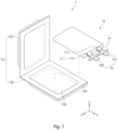
- FIG. 1 is an exploded perspective view illustrating a secondary battery according to an embodiment of the present invention.
- a secondary battery 1 may include an electrode assembly 10 and a case 13 surrounding the electrode assembly 10.
- the electrode assembly 10 is a power generation device, in which a positive electrode and a negative electrode are sequentially stacked in a state in which a separator is interposed therebetween, and may have a stacked type or stack and folding type structure.
- the separator included in the electrode assembly 10 may insulate the positive electrode and the negative electrode from each other.
- the electrode assembly 10 may include a plurality of electrode tabs 11 extending from the electrode assembly 10.
- the electrode assembly 10 may include a positive electrode tab 111 and a negative electrode tab 112.
- the positive electrode tab 111 may extend from the positive electrode of the electrode assembly 10 to protrude to the outside of the electrode assembly 10.
- the negative electrode tab 112 may extend from the negative electrode of the electrode assembly 10 to protrude to the outside of the electrode assembly 10.
- An electrode lead 12 may be connected to the electrode tab 11.
- the electrode lead 12 may be connected to the electrode tab 11 through a welding process such as laser welding.
- the electrode lead 12 may include a positive electrode lead 121 and a negative electrode lead 122. According to a formed position of each of the positive electrode tab 111 and the negative electrode tab 112, the positive electrode lead 121 and the negative electrode lead 122 may extend in the same direction or may extend in opposite directions.
- the positive electrode lead 121 and the negative electrode lead 122 may have different materials.
- the positive electrode lead 121 may have the same aluminum (Al) material as that of the positive electrode
- the negative electrode lead 122 may have the same copper (Cu) material as that of the negative electrode, or a copper material coated with nickel (Ni).
- a portion of the electrode lead 12, which protrudes to the outside of the case 13, may serve as a terminal portion to be electrically connected to an external terminal.
- the electrode lead 12 may have a portion that is surrounded by an insulation part 14.
- the insulation part 14 may be disposed on a sealing part 134, on which an upper pouch 131 and a lower pouch 132 of the case 13 are thermally fused to each other, to bond the electrode lead 12 to the case 13.
- electricity generated from the electrode assembly 10 may be prevented from flowing to the case 13 through the electrode lead 12, and sealing of the case 13 may be maintained.
- the insulation part 14 is made of a nonconductor having non-conductivity, through which electricity does not flow well.
- a material, which is easily attached to the electrode lead 12 and has a relatively small thickness, may be used in the insulation part 14.
- the insulation part 14 may be made of an insulation tape.
- the material of the insulation part 14 is not limited to the insulation tape, and various members may be used as long as the members are capable of insulating the electrode lead 12.
- the case 13 provides an accommodation space capable of accommodating the electrode assembly 10, and has a pouch shape as a whole.
- the case 13 may accommodate and seal the electrode assembly 10 so that a portion of the electrode lead 12, i.e., the terminal portion, is exposed.
- the case 13 includes the upper pouch 131 and the lower pouch 132.
- the lower pouch 132 is provided with an accommodation space 133 capable of accommodating the electrode assembly 10, and the upper pouch 131 covers the accommodation space 133 at an upper side so that the electrode assembly 10 is not separated to the outside of the case 13.
- the accommodation space 133 may be defined also in the upper pouch 131 to accommodate the electrode assembly 10 from the upper side.
- the upper pouch 131 and the lower pouch 132 may be manufactured so that respective sides of the upper pouch 131 and the lower pouch 132 are connected to each other, but an embodiment of the present invention is not limited thereto.
- the upper pouch 131 and the lower pouch 132 may be manufactured in various manner such as being divided to be separately manufactured.
- a unit electrode of at least one of the positive electrode and the negative electrode included in this electrode assembly 10 may be manufactured by coating a sheet-shaped electrode sheet with an active material, followed by drying and rolling, and then cutting the electrode sheet to have a fixed size.
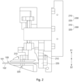
- FIG. 2 is a view illustrating an apparatus for manufacturing a secondary battery according to an embodiment of the present invention.
- the manufacturing apparatus illustrated in FIG. 2 may be an apparatus for cutting an electrode.
- the apparatus for cutting the electrode may include a gripper 300 and a cutter 200.
- the gripper 300 may be disposed in front of the cutter 200 in a direction in which an electrode sheet 100 is supplied.
- the gripper 300 may grip the electrode sheet 100 so that the electrode sheet 100 is cut by the cutter 200 in response to an operation of the cutter 200.
- the gripper 300 may be in close contact with each of both surfaces of the electrode sheet 100 to limit movement of the electrode sheet 100.
- the gripper 300 may include a first gripper 310 and a second gripper 320.
- the first gripper 310 may be in contact with a top surface 101 (or a surface facing a first direction D1) of the electrode sheet 100 during the cutting of the electrode sheet 100.
- the second gripper 320 may be in contact with a bottom surface 102 (or a surface facing a second direction D2) of the electrode sheet 100 during the cutting of the electrode sheet 100.
- At least one of the first gripper 310 or the second gripper 320 may move vertically (or in the first direction D1 and/or the second direction D2) so that the electrode sheet 100 is pressed.
- the first gripper 310 may move toward the second gripper 320 in the second direction D2 in a state in which the second gripper 320 is fixed, so that the both surfaces of the electrode assembly 100 are pressed through the first and second grippers 310 and 320.
- the cutter 200 may be disposed behind the gripper 300 in the direction in which the electrode sheet 100 is supplied.
- the cutter 200 may include a first cutter 210 and a second cutter 220.
- the first cutter 210 may be disposed to face the top surface 101 of the electrode sheet 100 with respect to the electrode sheet 100.
- the second cutter 220 may be disposed on the bottom surface 102 of the electrode sheet 100 with respect to the electrode sheet 100.
- At least one of the first cutter 210 or the second cutter 220 may perform an elevating motion at a cutting position of the electrode sheet 100.
- the first cutter 210 may perform the elevating motion so that a cutter blade of the first cutter 210 and a cutter blade of the second cutter 220 are in contact with each other, and thus, the electrode sheet 100 may be cut.
- the both surfaces of the electrode sheet 100 may be pressed by gripping (or holding) through the first gripper 310 and the second gripper 320.
- the electrode sheet 100 may be cut into the unit electrodes through the cutter 200 using the first cutter 210 and the second cutter 220.
- FIG. 3 is a cross-sectional view illustrating a gripper included in a cutting apparatus according to an embodiment of the present invention.
- a gripper 300 included in the cutting apparatus may include a first gripper 310 and a second gripper 320.
- the first gripper 310 may be disposed to face the second gripper 320 so that the first gripper 310 is in contact with a top surface of an electrode sheet (e.g., the top surface 101 of the electrode sheet 100 in FIG. 2 ) during cutting of the electrode sheet.
- the first gripper 310 may include a first area A1 and a second area A2 adjacent to the first area A1.
- a bottom surface of the first gripper 310 i.e., one surface facing the second gripper 320, may include the first area A1 and the second area A2.
- the second area A2 may be provided at at least one side of the first area A1.
- the second area A2 may be provided to surround the first area A1.
- the first area A1 of the first gripper 310 may have at least a portion that further protrudes in the second direction D2 facing the second gripper 320 than the second area A2 does.
- the first gripper 310 may include a protrusion 400 disposed at at least a portion of the first area A1.
- the protrusion 400 may protrude from a gripper plate 312 of the first gripper 310 toward the second gripper 320.
- the protrusion 400 may protrude from the gripper plate 312 of the first gripper 310 to have a polygonal shape or to be provided so that at least a portion has a curvature.
- the protrusion 400 may protrude from the gripper plate 312 of the first gripper 310 to have a rectangular shape.
- the protrusion 400 may be made of the same material as or a different material from that of the gripper plate 312 of the first gripper 310.
- the protrusion 400 may be made of the same material as that of the gripper plate 312 of the first gripper 310.
- the protrusion 400 made of the same material as that of the gripper plate 312 may be provided integrally with the gripper plate 312.
- a bottom surface (e.g., a surface facing the second direction D2) of the protrusion 400 and a top surface (e.g., a surface facing the first direction D1) of the second gripper 320 may be spaced a first spaced distance d1 from each other during an electrode cutting process.
- a bottom surface of the second gripper 320, which is disposed on the second area A2 of the first gripper 310, and the top surface of the second gripper 320 may be spaced a second spaced distance d2 from each other during the electrode cutting process.
- the first spaced distance d1 may be different from the second spaced distance d2.
- the first spaced distance d1 may be provided to be less than the second spaced distance d2.
- the first spaced distance d1 may have a size that corresponds to a thickness of the electrode sheet (e.g., the electrode sheet 100 in FIG. 2 ), and the second spaced distance d2 may have a thickness that is greater than a thickness of the electrode sheet.
- a height difference s1 (or stepped portion) between the bottom surface of the protrusion 400 and the gripper plate 312 disposed on the second area A2 of the first gripper 310 may correspond to a thickness of the protrusion 400.
- the height difference s1 between the bottom surface of the protrusion 400 and the gripper plate 312 disposed on the second area A2 of the first gripper 310 may be set in consideration of a thickness of a peripheral area of the electrode sheet.
- the height difference s1 between the bottom surface of the protrusion 400 and the gripper plate 312 disposed on the second area A2 of the first gripper 310 may be 0.4 mm to 0.6 mm.
- the protrusion 400 may be in contact with a partial area of the electrode sheet, which is fixed between the first gripper 210 and the second gripper 220 during the process of cutting the electrode sheet.
- the electrode sheet may include a central area and the peripheral area disposed at at least one side of the central area. The central area of the electrode sheet may be surrounded by the peripheral area of the electrode sheet.
- the first area A1 of the first gripper 310, on which the protrusion 400 is disposed, may press the central area other than the peripheral area of the electrode sheet in response to an operation of a cutter (e.g., the cutter 200 in FIG. 2 ).
- the protrusion 400 may not be in contact with the peripheral area of the electrode sheet and may be in contact with the central area of the electrode sheet.
- the protrusion 400 may have a size that is less than a size of a unit electrode, which is cut by the cutter, and/or the gripper plate 312.
- the protrusion 400 may have a length L1 that is less than a length of the unit electrode. As an example, the length L1 of the protrusion 400 may be provided to be about half the length of the unit electrode.
- the bottom surface of the protrusion 400 which is disposed on the first area A1 of the first gripper 310, may be in contact with the electrode sheet during the electrode cutting process.
- the gripper plate 312 disposed on the second area A2 of the first gripper 320 may not be in contact with the electrode sheet during the electrode cutting process.
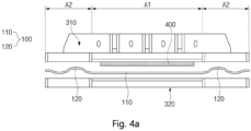
- FIGS. 4a and 4b are views for explaining an arrangement relationship between an electrode sheet and a gripper included in a cutting apparatus according to an embodiment of the present invention.
- an electrode sheet 100 may include a central area 110 and a peripheral area 120.
- the central area 110 of the electrode sheet 100 may have at least a portion that corresponds to a first area A1 of a first gripper 310.
- the peripheral area 120 of the electrode sheet 100 may have at least a portion that corresponds to a second area A2 of the first gripper 310.
- the central area 110 of the electrode sheet 100 may have a uniform surface.
- the peripheral area 120 of the electrode sheet 100 may have a surface that is relatively non-uniform compared to that of the central area 110 of the electrode sheet 100. In the peripheral area 120 of the electrode sheet 100, waves (or wrinkles) may occur in a process (e.g., an electrode roll press process) before the cutting process so that the surface of the peripheral area 120 of the electrode sheet 100 is non-uniform.
- a protrusion 400 of the first gripper 310 may press the electrode sheet 100.
- the protrusion 400 of the first gripper 310 may press the central area 110 of the electrode sheet 100.
- the protrusion 400 of the first gripper 310 may be provided to avoid the peripheral area 120 of the electrode sheet 100, in which waves are most likely to occur.
- the protrusion 400 of the first gripper 310 may not press the peripheral area 120 of the electrode sheet 100.
- the second area A2 of the first gripper 310 may not press the peripheral area 120 of the electrode sheet 100.
- the first gripper 310 may grip a partial area (an area excluding the peripheral area 120) of a top surface of the electrode sheet 100, not the entire area thereof. Accordingly, the present invention may prevent a positional defect (e.g., displacement) of the electrode sheet (or unit electrode) during a lamination process.
- displacement caused by an assembly tolerance may occur in at least one of the first gripper 310 or a second gripper 320. Even when the displacement occurs in the first gripper 310 due to the assembly tolerance, the first gripper 310 may not be in contact with (or press) the peripheral area 120 of the electrode sheet 100, in which waves are most likely to occur. Accordingly, the present invention may prevent the positional defect (e.g., displacement) of the electrode sheet (or unit electrode) during the lamination process.
- FIG. 5 is a view illustrating a gripper included in a cutting apparatus according to another embodiment of the present invention.
- the gripper illustrated in FIG. 5 may be substantially the same as the gripper 300 illustrated in FIGS. 3 to 4b except that an opening portion 500 of a first gripper 310 is provided in place of the protrusion 400 of the first gripper illustrated in FIGS. 3 to 4b .
- the description with reference to FIGS. 3 to 4b may apply to the description of remaining components except for the opening portion 500 of the first gripper 310, and duplicate description is omitted.
- a first area A1 of the first gripper 310 illustrated in FIG. 5 may have at least a portion that further protrudes in the second direction D2 facing the second gripper 320 than a second area A2 does.
- the first gripper 310 may include the opening portion 500 disposed at at least a portion of the second area A2.
- a bottom surface of a gripper plate 312, which is disposed on the first area A1 of the first gripper 310, and a top surface (e.g., a surface facing the first direction D1) of the second gripper 320 may be spaced a first spaced distance d1 from each other during the electrode cutting process.
- a bottom surface 501 provided by the opening portion 500 and the top surface of the second gripper 320 may be spaced a second spaced distance d2 from each other during the electrode cutting process.
- the first spaced distance d1 may be different from the second spaced distance d2.
- the first spaced distance d1 may be provided to be less than the second spaced distance d2.
- the first spaced distance d1 may have a size that corresponds to a thickness of an electrode sheet (e.g., the electrode sheet 100 in FIG. 2 ), and the second spaced distance d2 may have a thickness that is greater than a thickness of the electrode sheet.
- a height difference s2 (or stepped portion) between the bottom surface 501 provided by the opening portion 500 and the gripper plate 312 disposed on the first area A1 of the first gripper 310 may correspond to a depth of the opening portion 500.
- the height difference s2 between the bottom surface 501 of the opening portion 500 and the gripper plate 312 disposed on the first area A1 of the first gripper 310 may be set in consideration of a thickness of a peripheral area of the electrode sheet.
- the height difference s2 between the bottom surface 501 provided by the opening portion 500 and the gripper plate 312 disposed on the first area A1 of the first gripper 310 may be 0.4 mm to 0.6 mm.
- the gripper plate 312 of the first gripper 310 may be in contact with a partial area of the electrode sheet, which is fixed between the first gripper 210 and the second gripper 220 during the process of cutting the electrode sheet.
- the first gripper 310 may press the central area other than the peripheral area of the electrode sheet in response to an operation of a cutter (e.g., the cutter 200 in FIG. 2 ). Due to the opening portion 500, the first gripper 310 may not be in contact with the peripheral area of the electrode sheet and may be in contact with the central area of the electrode sheet.
- a gripper plate 312 of the first area A1, which further protrudes toward the second gripper 320 than the bottom surface 501 provided by the opening portion 500 does, may have a size that is less than a size of a unit electrode, which is cut by the cutter, and/or the gripper plate 312.
- the gripper plate 312 of the first area A1, which further protrudes than the bottom surface 501 provided by the opening portion 500 does, may have a length L2 that is less than a length of the unit electrode.
- the length L2 of the gripper plate 312 of the first area A1, which further protrudes than the bottom surface 501 provided by the opening portion 500 does, may be provided to be about half the length of the unit electrode.
- a bottom surface of the gripper plate 312 disposed on the first area A1 of the first gripper 310 may be in contact with the electrode sheet during the electrode cutting process.
- the gripper plate 312 disposed on the second area A2 of the first gripper 320 may not be in contact with at least a portion of the electrode sheet due to the opening portion 500 during the electrode cutting process.
- the gripper plate 312 disposed on the second area A2 of the first gripper 320 may not be in contact with (or press) the peripheral area 120 of the electrode sheet 100, in which waves are most likely to occur.
- the first gripper 310 may grip a partial area (an area excluding the peripheral area 120) of a top surface of the electrode sheet 100, not the entire area thereof. Accordingly, the present invention may prevent a positional defect (e.g., displacement) of the electrode sheet (or unit electrode) during the lamination process.
- a positional defect e.g., displacement
- the gripper plate 312 may have a thickness that is less than a thickness of the gripper plate 312 disposed on the first area A1 as illustrated in FIG. 5 .
- the opening portion 500 may have a groove shape that is concave from a bottom surface (e.g., a surface facing the second direction D2) of the gripper plate 312 toward a top surface (e.g., a surface facing the first direction D1) of the gripper plate 312.
- the gripper plate 312 On the remaining area of the second area A2 of the first gripper 310, the gripper plate 312 may have a thickness that is the same as that of the gripper plate 312 on the first area A1.
- the gripper plate 312 may be in contact with a portion of the peripheral area 120 of the electrode sheet 100, in which waves are most likely to occur, but the contact area between the gripper plate 312 and the electrode sheet may be minimized due to the opening portion 500. Accordingly, the positional defect (e.g., displacement) of the electrode sheet (or unit electrode) may be minimized during the lamination process.
- the gripper plate 312 may have a thickness that is less than a thickness of the gripper plate 312 disposed on the first area A1 due to the opening portion 500.
- the gripper plate 312 may not be in contact with the entirety of the peripheral area 120 of the electrode sheet 100, in which waves are most likely to occur. Accordingly, the positional defect (e.g., displacement) of the electrode sheet (or unit electrode) may be prevented during the lamination process.
- Electrode assembly 100 Electrode sheet 200: Cutter 300: Gripper 400: Protrusion 500: Opening portion
Landscapes
- Engineering & Computer Science (AREA)
- Life Sciences & Earth Sciences (AREA)
- Forests & Forestry (AREA)
- Mechanical Engineering (AREA)
- Manufacturing & Machinery (AREA)
- Chemical & Material Sciences (AREA)
- Chemical Kinetics & Catalysis (AREA)
- Electrochemistry (AREA)
- General Chemical & Material Sciences (AREA)
- Battery Electrode And Active Subsutance (AREA)
Abstract
Description
- The present application claims the benefit of the priority of
Korean Patent Application No. 10-2022-0022579, filed on February 21, 2022 - The present invention relates to an apparatus and method for cutting an electrode, and more particularly, to an apparatus and method for cutting an electrode, capable of minimizing an occurrence of displacement of an electrode sheet.
- A demand for secondary batteries as energy sources for electronic devices such as mobile phones, notebook computers, and wearable devices, and electric vehicles, etc., increases. According to the type of an electrode, the secondary batteries are classified into nickel-cadmium secondary batteries, nickel-hydrogen secondary batteries, lithium secondary batteries, and the like, and research on and development for the lithium secondary batteries, which have advantages such as a high operating voltage and a high energy density per unit weight, are actively carried out.
- In general, the secondary batteries may include an electrode assembly and a case in which the electrode assembly is embedded. The electrode assembly may have a structure in which a positive electrode and a negative electrode are sequentially stacked with a separator therebetween. A unit electrode such as the positive electrode and the negative electrode, may be manufactured by cutting an electrode sheet, which is made by applying an electrode active material, to have a unit electrode length. When cutting, a gripper that grips the electrode sheet may be in direct contact with waves (or wrinkles) of the electrode sheet, which occur during a roll press process, and thus, a defect in which the electrode sheet is displaced may occur. In addition, as the gripper displaced by an assembly tolerance of the gripper strongly presses the waves (or wrinkles) of the electrode sheet, the defect in which the electrode sheet is displaced may severely occur.
- An embodiment of the present invention is to provide an apparatus and method for cutting an electrode, capable of minimizing an occurrence of displacement of an electrode sheet.
- The technical objects of the present invention are not limited to the aforesaid, but other technical objects not described herein will be clearly understood by those skilled in the art from descriptions below.
- An apparatus for cutting an electrode according to an embodiment of the present invention may include: a cutter that cuts an electrode sheet into unit electrodes; and a first gripper and a second gripper that are disposed in front of the cutter to fix the electrode sheet at both sides, respectively, in response to an operation of the cutter, wherein the first gripper includes a first area and a second area disposed at at least one side of the first area, and the first area of the first gripper further protrudes toward the second gripper than the second area does.
- According to an embodiment, the first gripper may press a top surface of the electrode sheet, and the second gripper may press a bottom surface of the electrode sheet.
- According to an embodiment, the electrode sheet may include a central area and a peripheral area disposed at at least one side of the central area, and the first area of the first gripper may press the central area in addition to at least a portion of the peripheral area of the electrode sheet in response to an operation of the cutter.
- According to an embodiment, the first gripper may include a protrusion disposed at at least a portion of the first area and protruding in a direction facing the second gripper.
- According to an embodiment, a height difference between a bottom surface of the protrusion and a bottom surface of the second area of the first gripper may be 0.4 mm to 0.6 mm.
- According to an embodiment, the protrusion may have a length that is less than a length of each of the unit electrodes.
- According to an embodiment, the first gripper may include an opening portion that is disposed on the second area and is concave in a direction opposite to a direction facing the second gripper.
- According to an embodiment, a height difference between a bottom surface provided by the opening portion and a bottom surface of the first area of the first gripper may be 4 mm to 6 mm.
- A method for cutting an electrode according to an embodiment of the present invention may include: pressing and fixing an electrode sheet at both sides by a first gripper and a second gripper, respectively; and cutting the electrode sheet into unit electrodes by a cutter disposed behind the first gripper and the second gripper, wherein the first gripper includes a first area and a second area disposed at at least one side of the first area, and the first area of the first gripper further protrudes toward the second gripper than the second area does.
- According to an embodiment, the electrode sheet may include a central area and a peripheral area disposed at at least one side of the central area, wherein the fixing of the electrode sheet includes pressing the central area other than the peripheral area of the electrode sheet by a protrusion disposed on the first area of the first gripper.
- According to the embodiment of the present invention, the first gripper may press the remaining area of the electrode sheet except for the peripheral area of the electrode sheet so that the first gripper avoids being in direct contact with the peripheral area of the electrode sheet. Accordingly, the present invention may prevent the positional defect (e.g., displacement) of the electrode sheet (or unit electrode) during the lamination process.
- Moreover, according to the embodiment of the present invention, even when the displacement of the gripper caused by the assembly tolerance occurs, the direct contact between the gripper and the peripheral area of the electrode sheet may be avoided. Accordingly, the present invention may reduce the process defects likely to occur due to the displacement of the gripper.
- In addition, the various effects directly or indirectly found through this document may be provided.
-
-
FIG. 1 is an exploded perspective view illustrating a secondary battery according to an embodiment of the present invention. -
FIG. 2 is a view illustrating an apparatus for manufacturing a secondary battery according to an embodiment of the present invention. -
FIG. 3 is a cross-sectional view illustrating a gripper included in a cutting apparatus according to an embodiment of the present invention. -
FIGS. 4a and4b are views for explaining an arrangement relationship between an electrode sheet and a gripper included in a cutting apparatus according to an embodiment of the present invention. -
FIG. 5 is a view illustrating a gripper included in a cutting apparatus according to another embodiment of the present invention. - Hereinafter, preferred embodiments of the present invention will be described in detail with reference to the accompanying drawings to enable those skilled in the art to which the present invention pertains to easily carry out the present invention. The present invention may, however, be embodied in different forms and should not be construed as limited by the embodiments set forth herein.
- The parts unrelated to the description, or the detailed descriptions of related well-known art that may unnecessarily obscure subject matters of the present invention, will be ruled out in order to clearly describe the present invention. Like reference numerals refer to like elements throughout the whole specification.
- Moreover, terms or words used in this specification and claims should not be restrictively interpreted as ordinary meanings or dictionary-based meanings, but should be interpreted as meanings and concepts conforming to the scope of the present invention on the basis of the principle that an inventor can properly define the concept of a term to describe and explain his or her invention in the best ways.
-
FIG. 1 is an exploded perspective view illustrating a secondary battery according to an embodiment of the present invention. - Referring to
FIG. 1 , asecondary battery 1 according to an embodiment of the present invention may include anelectrode assembly 10 and acase 13 surrounding theelectrode assembly 10. - The
electrode assembly 10 is a power generation device, in which a positive electrode and a negative electrode are sequentially stacked in a state in which a separator is interposed therebetween, and may have a stacked type or stack and folding type structure. The separator included in theelectrode assembly 10 may insulate the positive electrode and the negative electrode from each other. - The
electrode assembly 10 may include a plurality ofelectrode tabs 11 extending from theelectrode assembly 10. Theelectrode assembly 10 may include apositive electrode tab 111 and anegative electrode tab 112. Thepositive electrode tab 111 may extend from the positive electrode of theelectrode assembly 10 to protrude to the outside of theelectrode assembly 10. Thenegative electrode tab 112 may extend from the negative electrode of theelectrode assembly 10 to protrude to the outside of theelectrode assembly 10. - An
electrode lead 12 may be connected to theelectrode tab 11. For example, theelectrode lead 12 may be connected to theelectrode tab 11 through a welding process such as laser welding. Theelectrode lead 12 may include apositive electrode lead 121 and anegative electrode lead 122. According to a formed position of each of thepositive electrode tab 111 and thenegative electrode tab 112, thepositive electrode lead 121 and thenegative electrode lead 122 may extend in the same direction or may extend in opposite directions. The positive electrode lead 121 and thenegative electrode lead 122 may have different materials. For example, thepositive electrode lead 121 may have the same aluminum (Al) material as that of the positive electrode, and thenegative electrode lead 122 may have the same copper (Cu) material as that of the negative electrode, or a copper material coated with nickel (Ni). A portion of theelectrode lead 12, which protrudes to the outside of thecase 13, may serve as a terminal portion to be electrically connected to an external terminal. - The
electrode lead 12 may have a portion that is surrounded by aninsulation part 14. Theinsulation part 14 may be disposed on a sealingpart 134, on which anupper pouch 131 and alower pouch 132 of thecase 13 are thermally fused to each other, to bond theelectrode lead 12 to thecase 13. In addition, electricity generated from theelectrode assembly 10 may be prevented from flowing to thecase 13 through theelectrode lead 12, and sealing of thecase 13 may be maintained. Theinsulation part 14 is made of a nonconductor having non-conductivity, through which electricity does not flow well. A material, which is easily attached to theelectrode lead 12 and has a relatively small thickness, may be used in theinsulation part 14. For example, theinsulation part 14 may be made of an insulation tape. The material of theinsulation part 14 is not limited to the insulation tape, and various members may be used as long as the members are capable of insulating theelectrode lead 12. - The
case 13 provides an accommodation space capable of accommodating theelectrode assembly 10, and has a pouch shape as a whole. Thecase 13 may accommodate and seal theelectrode assembly 10 so that a portion of theelectrode lead 12, i.e., the terminal portion, is exposed. Thecase 13 includes theupper pouch 131 and thelower pouch 132. Thelower pouch 132 is provided with anaccommodation space 133 capable of accommodating theelectrode assembly 10, and theupper pouch 131 covers theaccommodation space 133 at an upper side so that theelectrode assembly 10 is not separated to the outside of thecase 13. Here, theaccommodation space 133 may be defined also in theupper pouch 131 to accommodate theelectrode assembly 10 from the upper side. Theupper pouch 131 and thelower pouch 132 may be manufactured so that respective sides of theupper pouch 131 and thelower pouch 132 are connected to each other, but an embodiment of the present invention is not limited thereto. For example, theupper pouch 131 and thelower pouch 132 may be manufactured in various manner such as being divided to be separately manufactured. - A unit electrode of at least one of the positive electrode and the negative electrode included in this
electrode assembly 10 may be manufactured by coating a sheet-shaped electrode sheet with an active material, followed by drying and rolling, and then cutting the electrode sheet to have a fixed size. -
FIG. 2 is a view illustrating an apparatus for manufacturing a secondary battery according to an embodiment of the present invention. The manufacturing apparatus illustrated inFIG. 2 may be an apparatus for cutting an electrode. - Referring to
FIG. 2 , the apparatus for cutting the electrode according to an embodiment of the present invention may include agripper 300 and acutter 200. - The
gripper 300 may be disposed in front of thecutter 200 in a direction in which anelectrode sheet 100 is supplied. Thegripper 300 may grip theelectrode sheet 100 so that theelectrode sheet 100 is cut by thecutter 200 in response to an operation of thecutter 200. When thecutter 200 cuts theelectrode sheet 100 into unit electrodes, thegripper 300 may be in close contact with each of both surfaces of theelectrode sheet 100 to limit movement of theelectrode sheet 100. Thegripper 300 may include afirst gripper 310 and asecond gripper 320. Thefirst gripper 310 may be in contact with a top surface 101 (or a surface facing a first direction D1) of theelectrode sheet 100 during the cutting of theelectrode sheet 100. Thesecond gripper 320 may be in contact with a bottom surface 102 (or a surface facing a second direction D2) of theelectrode sheet 100 during the cutting of theelectrode sheet 100. - At least one of the
first gripper 310 or thesecond gripper 320 may move vertically (or in the first direction D1 and/or the second direction D2) so that theelectrode sheet 100 is pressed. For example, thefirst gripper 310 may move toward thesecond gripper 320 in the second direction D2 in a state in which thesecond gripper 320 is fixed, so that the both surfaces of theelectrode assembly 100 are pressed through the first andsecond grippers - The
cutter 200 may be disposed behind thegripper 300 in the direction in which theelectrode sheet 100 is supplied. Thecutter 200 may include afirst cutter 210 and asecond cutter 220. Thefirst cutter 210 may be disposed to face thetop surface 101 of theelectrode sheet 100 with respect to theelectrode sheet 100. Thesecond cutter 220 may be disposed on thebottom surface 102 of theelectrode sheet 100 with respect to theelectrode sheet 100. At least one of thefirst cutter 210 or thesecond cutter 220 may perform an elevating motion at a cutting position of theelectrode sheet 100. For example, when theelectrode sheet 100 is transferred, thefirst cutter 210 may perform the elevating motion so that a cutter blade of thefirst cutter 210 and a cutter blade of thesecond cutter 220 are in contact with each other, and thus, theelectrode sheet 100 may be cut. - According to an embodiment, the both surfaces of the
electrode sheet 100 may be pressed by gripping (or holding) through thefirst gripper 310 and thesecond gripper 320. In a state in which the both surfaces of theelectrode sheet 100 are pressed, theelectrode sheet 100 may be cut into the unit electrodes through thecutter 200 using thefirst cutter 210 and thesecond cutter 220. -
FIG. 3 is a cross-sectional view illustrating a gripper included in a cutting apparatus according to an embodiment of the present invention. - Referring to
FIG. 3 , agripper 300 included in the cutting apparatus according to an embodiment of the present invention may include afirst gripper 310 and asecond gripper 320. - The
first gripper 310 may be disposed to face thesecond gripper 320 so that thefirst gripper 310 is in contact with a top surface of an electrode sheet (e.g., thetop surface 101 of theelectrode sheet 100 inFIG. 2 ) during cutting of the electrode sheet. Thefirst gripper 310 may include a first area A1 and a second area A2 adjacent to the first area A1. In more detail, a bottom surface of thefirst gripper 310, i.e., one surface facing thesecond gripper 320, may include the first area A1 and the second area A2. - The second area A2 may be provided at at least one side of the first area A1. For example, the second area A2 may be provided to surround the first area A1.
- The first area A1 of the
first gripper 310 may have at least a portion that further protrudes in the second direction D2 facing thesecond gripper 320 than the second area A2 does. Thefirst gripper 310 may include aprotrusion 400 disposed at at least a portion of the first area A1. Theprotrusion 400 may protrude from agripper plate 312 of thefirst gripper 310 toward thesecond gripper 320. Theprotrusion 400 may protrude from thegripper plate 312 of thefirst gripper 310 to have a polygonal shape or to be provided so that at least a portion has a curvature. For example, theprotrusion 400 may protrude from thegripper plate 312 of thefirst gripper 310 to have a rectangular shape. - The
protrusion 400 may be made of the same material as or a different material from that of thegripper plate 312 of thefirst gripper 310. For example, theprotrusion 400 may be made of the same material as that of thegripper plate 312 of thefirst gripper 310. Theprotrusion 400 made of the same material as that of thegripper plate 312 may be provided integrally with thegripper plate 312. - A bottom surface (e.g., a surface facing the second direction D2) of the
protrusion 400 and a top surface (e.g., a surface facing the first direction D1) of thesecond gripper 320 may be spaced a first spaced distance d1 from each other during an electrode cutting process. A bottom surface of thesecond gripper 320, which is disposed on the second area A2 of thefirst gripper 310, and the top surface of thesecond gripper 320 may be spaced a second spaced distance d2 from each other during the electrode cutting process. The first spaced distance d1 may be different from the second spaced distance d2. The first spaced distance d1 may be provided to be less than the second spaced distance d2. During the electrode cutting process, the first spaced distance d1 may have a size that corresponds to a thickness of the electrode sheet (e.g., theelectrode sheet 100 inFIG. 2 ), and the second spaced distance d2 may have a thickness that is greater than a thickness of the electrode sheet. - A height difference s1 (or stepped portion) between the bottom surface of the
protrusion 400 and thegripper plate 312 disposed on the second area A2 of thefirst gripper 310 may correspond to a thickness of theprotrusion 400. The height difference s1 between the bottom surface of theprotrusion 400 and thegripper plate 312 disposed on the second area A2 of thefirst gripper 310 may be set in consideration of a thickness of a peripheral area of the electrode sheet. For example, the height difference s1 between the bottom surface of theprotrusion 400 and thegripper plate 312 disposed on the second area A2 of thefirst gripper 310 may be 0.4 mm to 0.6 mm. - The
protrusion 400 may be in contact with a partial area of the electrode sheet, which is fixed between thefirst gripper 210 and thesecond gripper 220 during the process of cutting the electrode sheet. The electrode sheet may include a central area and the peripheral area disposed at at least one side of the central area. The central area of the electrode sheet may be surrounded by the peripheral area of the electrode sheet. - The first area A1 of the
first gripper 310, on which theprotrusion 400 is disposed, may press the central area other than the peripheral area of the electrode sheet in response to an operation of a cutter (e.g., thecutter 200 inFIG. 2 ). Theprotrusion 400 may not be in contact with the peripheral area of the electrode sheet and may be in contact with the central area of the electrode sheet. Theprotrusion 400 may have a size that is less than a size of a unit electrode, which is cut by the cutter, and/or thegripper plate 312. Theprotrusion 400 may have a length L1 that is less than a length of the unit electrode. As an example, the length L1 of theprotrusion 400 may be provided to be about half the length of the unit electrode. - As above, the bottom surface of the
protrusion 400, which is disposed on the first area A1 of thefirst gripper 310, may be in contact with the electrode sheet during the electrode cutting process. Thegripper plate 312 disposed on the second area A2 of thefirst gripper 320 may not be in contact with the electrode sheet during the electrode cutting process. -
FIGS. 4a and4b are views for explaining an arrangement relationship between an electrode sheet and a gripper included in a cutting apparatus according to an embodiment of the present invention. - Referring to
FIGS. 4a and4b , anelectrode sheet 100 may include acentral area 110 and aperipheral area 120. Thecentral area 110 of theelectrode sheet 100 may have at least a portion that corresponds to a first area A1 of afirst gripper 310. Theperipheral area 120 of theelectrode sheet 100 may have at least a portion that corresponds to a second area A2 of thefirst gripper 310. Thecentral area 110 of theelectrode sheet 100 may have a uniform surface. Theperipheral area 120 of theelectrode sheet 100 may have a surface that is relatively non-uniform compared to that of thecentral area 110 of theelectrode sheet 100. In theperipheral area 120 of theelectrode sheet 100, waves (or wrinkles) may occur in a process (e.g., an electrode roll press process) before the cutting process so that the surface of theperipheral area 120 of theelectrode sheet 100 is non-uniform. - During the process of cutting the
electrode sheet 100, aprotrusion 400 of thefirst gripper 310 may press theelectrode sheet 100. Theprotrusion 400 of thefirst gripper 310 may press thecentral area 110 of theelectrode sheet 100. Theprotrusion 400 of thefirst gripper 310 may be provided to avoid theperipheral area 120 of theelectrode sheet 100, in which waves are most likely to occur. Theprotrusion 400 of thefirst gripper 310 may not press theperipheral area 120 of theelectrode sheet 100. The second area A2 of thefirst gripper 310 may not press theperipheral area 120 of theelectrode sheet 100. As above, thefirst gripper 310 may grip a partial area (an area excluding the peripheral area 120) of a top surface of theelectrode sheet 100, not the entire area thereof. Accordingly, the present invention may prevent a positional defect (e.g., displacement) of the electrode sheet (or unit electrode) during a lamination process. - In addition, as illustrated in
FIG. 4b , displacement caused by an assembly tolerance may occur in at least one of thefirst gripper 310 or asecond gripper 320. Even when the displacement occurs in thefirst gripper 310 due to the assembly tolerance, thefirst gripper 310 may not be in contact with (or press) theperipheral area 120 of theelectrode sheet 100, in which waves are most likely to occur. Accordingly, the present invention may prevent the positional defect (e.g., displacement) of the electrode sheet (or unit electrode) during the lamination process. -
FIG. 5 is a view illustrating a gripper included in a cutting apparatus according to another embodiment of the present invention. The gripper illustrated inFIG. 5 may be substantially the same as thegripper 300 illustrated inFIGS. 3 to 4b except that anopening portion 500 of afirst gripper 310 is provided in place of theprotrusion 400 of the first gripper illustrated inFIGS. 3 to 4b . The description with reference toFIGS. 3 to 4b may apply to the description of remaining components except for theopening portion 500 of thefirst gripper 310, and duplicate description is omitted. - A first area A1 of the
first gripper 310 illustrated inFIG. 5 may have at least a portion that further protrudes in the second direction D2 facing thesecond gripper 320 than a second area A2 does. Thefirst gripper 310 may include theopening portion 500 disposed at at least a portion of the second area A2. - A bottom surface of a
gripper plate 312, which is disposed on the first area A1 of thefirst gripper 310, and a top surface (e.g., a surface facing the first direction D1) of thesecond gripper 320 may be spaced a first spaced distance d1 from each other during the electrode cutting process. Abottom surface 501 provided by theopening portion 500 and the top surface of thesecond gripper 320 may be spaced a second spaced distance d2 from each other during the electrode cutting process. The first spaced distance d1 may be different from the second spaced distance d2. The first spaced distance d1 may be provided to be less than the second spaced distance d2. During the electrode cutting process, the first spaced distance d1 may have a size that corresponds to a thickness of an electrode sheet (e.g., theelectrode sheet 100 inFIG. 2 ), and the second spaced distance d2 may have a thickness that is greater than a thickness of the electrode sheet. - A height difference s2 (or stepped portion) between the
bottom surface 501 provided by theopening portion 500 and thegripper plate 312 disposed on the first area A1 of thefirst gripper 310 may correspond to a depth of theopening portion 500. The height difference s2 between thebottom surface 501 of theopening portion 500 and thegripper plate 312 disposed on the first area A1 of thefirst gripper 310 may be set in consideration of a thickness of a peripheral area of the electrode sheet. For example, the height difference s2 between thebottom surface 501 provided by theopening portion 500 and thegripper plate 312 disposed on the first area A1 of thefirst gripper 310 may be 0.4 mm to 0.6 mm. - The
gripper plate 312 of thefirst gripper 310 may be in contact with a partial area of the electrode sheet, which is fixed between thefirst gripper 210 and thesecond gripper 220 during the process of cutting the electrode sheet. Thefirst gripper 310 may press the central area other than the peripheral area of the electrode sheet in response to an operation of a cutter (e.g., thecutter 200 inFIG. 2 ). Due to theopening portion 500, thefirst gripper 310 may not be in contact with the peripheral area of the electrode sheet and may be in contact with the central area of the electrode sheet. - A
gripper plate 312 of the first area A1, which further protrudes toward thesecond gripper 320 than thebottom surface 501 provided by theopening portion 500 does, may have a size that is less than a size of a unit electrode, which is cut by the cutter, and/or thegripper plate 312. Thegripper plate 312 of the first area A1, which further protrudes than thebottom surface 501 provided by theopening portion 500 does, may have a length L2 that is less than a length of the unit electrode. As an example, the length L2 of thegripper plate 312 of the first area A1, which further protrudes than thebottom surface 501 provided by theopening portion 500 does, may be provided to be about half the length of the unit electrode. - A bottom surface of the
gripper plate 312 disposed on the first area A1 of thefirst gripper 310 may be in contact with the electrode sheet during the electrode cutting process. Thegripper plate 312 disposed on the second area A2 of thefirst gripper 320 may not be in contact with at least a portion of the electrode sheet due to theopening portion 500 during the electrode cutting process. Thegripper plate 312 disposed on the second area A2 of thefirst gripper 320 may not be in contact with (or press) theperipheral area 120 of theelectrode sheet 100, in which waves are most likely to occur. - As above, the
first gripper 310 may grip a partial area (an area excluding the peripheral area 120) of a top surface of theelectrode sheet 100, not the entire area thereof. Accordingly, the present invention may prevent a positional defect (e.g., displacement) of the electrode sheet (or unit electrode) during the lamination process. - According to an embodiment, on a partial area of the second area A2 of the
first gripper 310, thegripper plate 312 may have a thickness that is less than a thickness of thegripper plate 312 disposed on the first area A1 as illustrated inFIG. 5 . As illustrated inFIG. 5 , theopening portion 500 may have a groove shape that is concave from a bottom surface (e.g., a surface facing the second direction D2) of thegripper plate 312 toward a top surface (e.g., a surface facing the first direction D1) of thegripper plate 312. On the remaining area of the second area A2 of thefirst gripper 310, thegripper plate 312 may have a thickness that is the same as that of thegripper plate 312 on the first area A1. In this case, thegripper plate 312 may be in contact with a portion of theperipheral area 120 of theelectrode sheet 100, in which waves are most likely to occur, but the contact area between thegripper plate 312 and the electrode sheet may be minimized due to theopening portion 500. Accordingly, the positional defect (e.g., displacement) of the electrode sheet (or unit electrode) may be minimized during the lamination process. - According to another embodiment, on the entire area of the second area A2 of the
first gripper 310, thegripper plate 312 may have a thickness that is less than a thickness of thegripper plate 312 disposed on the first area A1 due to theopening portion 500. In this case, thegripper plate 312 may not be in contact with the entirety of theperipheral area 120 of theelectrode sheet 100, in which waves are most likely to occur. Accordingly, the positional defect (e.g., displacement) of the electrode sheet (or unit electrode) may be prevented during the lamination process. - Although the present invention has been described with reference to the limited embodiments and drawings, the present invention is not limited thereto and may be variously implemented by those of ordinary skill in the art to which the present invention pertains, within the technical idea of the present invention and an equivalent of the appended claims.
-
1: Secondary battery 10: Electrode assembly 100: Electrode sheet 200: Cutter 300: Gripper 400: Protrusion 500: Opening portion
Claims (10)
- An apparatus for cutting an electrode, the apparatus comprising:a cutter configured to cut an electrode sheet into unit electrodes; anda first gripper and a second gripper that are disposed in front of the cutter to fix the electrode sheet at both sides, respectively, in response to an operation of the cutter,wherein the first gripper comprises a first area and a second area disposed at at least one side of the first area,
wherein the first area of the first gripper further protrudes toward the second gripper than the second area does. - The apparatus of claim 1, wherein the first gripper presses a top surface of the electrode sheet, and
the second gripper presses a bottom surface of the electrode sheet. - The apparatus of claim 1, wherein the electrode sheet comprises a central area and a peripheral area disposed at at least one side of the central area,
wherein the first area of the first gripper presses the central area in addition to at least a portion of the peripheral area of the electrode sheet in response to an operation of the cutter. - The apparatus of claim 1, wherein the first gripper comprises a protrusion disposed at at least a portion of the first area and protruding in a direction facing the second gripper.
- The apparatus of claim 4, wherein a height difference between a bottom surface of the protrusion and a bottom surface of the second area of the first gripper is in a range of 0.4 mm to 0.6 mm.
- The apparatus of claim 4, wherein the protrusion has a length that is less than a length of each of the unit electrodes.
- The apparatus of claim 1, wherein the first gripper comprises an opening portion that is disposed at the at least a portion of the second area and is concave in a direction opposite to a direction facing the second gripper.
- The apparatus of claim 7, wherein a height difference between a bottom surface provided by the opening portion and a bottom surface of the first area of the first gripper is in a range of 4 mm to 6 mm.
- A method for cutting an electrode, the method comprising:pressing and fixing an electrode sheet at both sides by a first gripper and a second gripper, respectively; andcutting the electrode sheet into unit electrodes by a cutter disposed behind the first gripper and the second gripper,wherein the first gripper comprises a first area and a second area disposed at at least one side of the first area,
wherein the first area of the first gripper further protrudes toward the second gripper than the second area does. - The method of claim 9, wherein the electrode sheet comprises a central area and a peripheral area disposed at at least one side of the central area,
wherein the fixing of the electrode sheet comprises pressing the central area other than the peripheral area of the electrode sheet by a protrusion disposed on the first area of the first gripper.
Applications Claiming Priority (2)
| Application Number | Priority Date | Filing Date | Title |
|---|---|---|---|
| KR1020220022579A KR20230125675A (en) | 2022-02-21 | 2022-02-21 | Cutting device and method for electrode |
| PCT/KR2023/002462 WO2023158287A1 (en) | 2022-02-21 | 2023-02-21 | Electrode cutting device and method |
Publications (2)
| Publication Number | Publication Date |
|---|---|
| EP4485554A1 true EP4485554A1 (en) | 2025-01-01 |
| EP4485554A4 EP4485554A4 (en) | 2025-08-27 |
Family
ID=87578675
Family Applications (1)
| Application Number | Title | Priority Date | Filing Date |
|---|---|---|---|
| EP23756699.7A Pending EP4485554A4 (en) | 2022-02-21 | 2023-02-21 | ELECTRODE CUTTING DEVICE AND METHOD |
Country Status (6)
| Country | Link |
|---|---|
| US (1) | US20250091240A1 (en) |
| EP (1) | EP4485554A4 (en) |
| JP (1) | JP7799943B2 (en) |
| KR (1) | KR20230125675A (en) |
| CN (1) | CN118476047A (en) |
| WO (1) | WO2023158287A1 (en) |
Family Cites Families (16)
| Publication number | Priority date | Publication date | Assignee | Title |
|---|---|---|---|---|
| JPS5537114U (en) * | 1978-08-25 | 1980-03-10 | ||
| JP2004103485A (en) * | 2002-09-12 | 2004-04-02 | Sony Corp | Core and winding device |
| KR101271492B1 (en) * | 2010-12-02 | 2013-06-05 | 주식회사 엘지화학 | Novel Device for Cutting Electrode Sheet and Secondary Battery Manufactured Using the Same |
| JP5706742B2 (en) * | 2011-04-07 | 2015-04-22 | 株式会社京都製作所 | Battery electrode material cutting device and method thereof |
| CN105592989B (en) * | 2013-09-30 | 2018-10-12 | 日产自动车株式会社 | Metal foil cutting device |
| JP6372453B2 (en) | 2015-09-07 | 2018-08-15 | トヨタ自動車株式会社 | Manufacturing method of laminated electrode body |
| JP6958004B2 (en) | 2017-06-13 | 2021-11-02 | 三洋電機株式会社 | Rechargeable battery |
| KR101963739B1 (en) * | 2017-11-07 | 2019-03-29 | (주)피토 | Separation film finishing apparatus of stacked secondary battery |
| KR101974438B1 (en) * | 2018-07-16 | 2019-05-02 | 주식회사 셀텍 | Automatic cutting device for residual part of terrace part of secondary battery cell |
| KR102655101B1 (en) * | 2018-11-23 | 2024-04-08 | 주식회사 엘지에너지솔루션 | Electrode lead cutting apparatus of battery cell |
| CN210272578U (en) | 2019-09-24 | 2020-04-07 | 苏州杰锐思智能科技股份有限公司 | Cell edge cutting device |
| KR102416147B1 (en) * | 2020-04-07 | 2022-07-06 | (주)펨트론 | Metal cutting apparatus for manufacturing a lead tab |
| CN213038087U (en) | 2020-06-12 | 2021-04-23 | 阜城县华兴服装有限公司 | A tailor device for clothing production |
| KR20220022579A (en) | 2020-08-19 | 2022-02-28 | 안시은 | Vessel for facial mask |
| KR102363870B1 (en) * | 2020-11-13 | 2022-02-18 | 주식회사 디에이테크놀로지 | Apparatus for Cutting Electrode for Secondary Battery |
| CN215800627U (en) | 2021-09-01 | 2022-02-11 | 杭州格美五金机电有限公司 | Stable car seat face cover cutting device of centre gripping |
-
2022
- 2022-02-21 KR KR1020220022579A patent/KR20230125675A/en active Pending
-
2023
- 2023-02-21 EP EP23756699.7A patent/EP4485554A4/en active Pending
- 2023-02-21 CN CN202380015806.5A patent/CN118476047A/en active Pending
- 2023-02-21 WO PCT/KR2023/002462 patent/WO2023158287A1/en not_active Ceased
- 2023-02-21 JP JP2024546311A patent/JP7799943B2/en active Active
- 2023-02-21 US US18/727,840 patent/US20250091240A1/en active Pending
Also Published As
| Publication number | Publication date |
|---|---|
| CN118476047A (en) | 2024-08-09 |
| JP7799943B2 (en) | 2026-01-16 |
| WO2023158287A1 (en) | 2023-08-24 |
| EP4485554A4 (en) | 2025-08-27 |
| KR20230125675A (en) | 2023-08-29 |
| JP2025504161A (en) | 2025-02-06 |
| US20250091240A1 (en) | 2025-03-20 |
Similar Documents
| Publication | Publication Date | Title |
|---|---|---|
| JP6884795B2 (en) | Stepped electrochemical cell with folded encapsulation | |
| US7364817B2 (en) | Secondary battery and method of manufacturing the same | |
| EP4057438A1 (en) | Electrode tab bending apparatus and method | |
| EP4325637A1 (en) | Secondary battery, and battery pack and vehicle comprising same | |
| US20250153262A1 (en) | Welding Apparatus and Welding Method | |
| EP4432455A1 (en) | Electrode tab welding apparatus, electrode tab welding method, and secondary battery | |
| EP3804019B1 (en) | Battery including bipolar cells that have an edge insulating device supported by a support frame | |
| US10446807B2 (en) | Secondary battery | |
| KR20170050445A (en) | Pouch type secondary battery | |
| US20220247045A1 (en) | Electrode terminal and use thereof | |
| KR102561762B1 (en) | Secondary battery | |
| US20250091240A1 (en) | Apparatus and Method for Cutting Electrode | |
| KR20180034903A (en) | Battery Cell Comprising Battery Case Having Receiving Part and Groove for Electrode Lead | |
| KR20170050444A (en) | Pouch type secondary battery | |
| EP3385998B1 (en) | Secondary battery comprising electrode lead and method for manufacturing secondary battery | |
| KR102546635B1 (en) | Method of manufacturing pocketing positive electrode body and pocketing positive electrode body | |
| EP3804017B1 (en) | Battery including bipolar cells that have a cell edge seal | |
| KR20220054939A (en) | Method of manufacturing pocketing positive electrode body, pocketing positive electrode body and electrode assembly comprising pocketing positive electrode body | |
| EP4726833A1 (en) | Secondary battery pressing device and secondary battery pressing method using same | |
| EP4708419A1 (en) | Device for manufacturing secondary battery, and method of manufacturing secondary battery | |
| US20250316745A1 (en) | Secondary battery | |
| EP4579891A1 (en) | Secondary battery, manufacturing method for same secondary battery, and pressing device used for same manufacturing method | |
| US20260106278A1 (en) | Battery module | |
| EP4674596A1 (en) | Molding device | |
| US20260024799A1 (en) | Electrode tab bending device and electrode tab bending method |
Legal Events
| Date | Code | Title | Description |
|---|---|---|---|
| STAA | Information on the status of an ep patent application or granted ep patent |
Free format text: STATUS: THE INTERNATIONAL PUBLICATION HAS BEEN MADE |
|
| PUAI | Public reference made under article 153(3) epc to a published international application that has entered the european phase |
Free format text: ORIGINAL CODE: 0009012 |
|
| STAA | Information on the status of an ep patent application or granted ep patent |
Free format text: STATUS: REQUEST FOR EXAMINATION WAS MADE |
|
| 17P | Request for examination filed |
Effective date: 20240626 |
|
| AK | Designated contracting states |
Kind code of ref document: A1 Designated state(s): AL AT BE BG CH CY CZ DE DK EE ES FI FR GB GR HR HU IE IS IT LI LT LU LV MC ME MK MT NL NO PL PT RO RS SE SI SK SM TR |
|
| DAV | Request for validation of the european patent (deleted) | ||
| DAX | Request for extension of the european patent (deleted) | ||
| A4 | Supplementary search report drawn up and despatched |
Effective date: 20250730 |
|
| RIC1 | Information provided on ipc code assigned before grant |
Ipc: H01M 4/04 20060101AFI20250724BHEP Ipc: B65H 35/04 20060101ALI20250724BHEP Ipc: H01M 10/04 20060101ALI20250724BHEP Ipc: B26D 7/01 20060101ALI20250724BHEP Ipc: B26D 7/02 20060101ALN20250724BHEP |
|
| STAA | Information on the status of an ep patent application or granted ep patent |
Free format text: STATUS: EXAMINATION IS IN PROGRESS |
|
| 17Q | First examination report despatched |
Effective date: 20260225 |