EP4485492A1 - Arc chute and load break switch comprising same - Google Patents
Arc chute and load break switch comprising same Download PDFInfo
- Publication number
- EP4485492A1 EP4485492A1 EP23760284.2A EP23760284A EP4485492A1 EP 4485492 A1 EP4485492 A1 EP 4485492A1 EP 23760284 A EP23760284 A EP 23760284A EP 4485492 A1 EP4485492 A1 EP 4485492A1
- Authority
- EP
- European Patent Office
- Prior art keywords
- arc
- top cover
- grid
- arc chute
- fixed terminal
- Prior art date
- Legal status (The legal status is an assumption and is not a legal conclusion. Google has not performed a legal analysis and makes no representation as to the accuracy of the status listed.)
- Pending
Links
Images









Classifications
-
- H—ELECTRICITY
- H01—ELECTRIC ELEMENTS
- H01H—ELECTRIC SWITCHES; RELAYS; SELECTORS; EMERGENCY PROTECTIVE DEVICES
- H01H33/00—High-tension or heavy-current switches with arc-extinguishing or arc-preventing means
- H01H33/02—Details
- H01H33/04—Means for extinguishing or preventing arc between current-carrying parts
- H01H33/18—Means for extinguishing or preventing arc between current-carrying parts using blow-out magnet
- H01H33/187—Means for extinguishing or preventing arc between current-carrying parts using blow-out magnet comprising a hollow annular arc runner and a central contact between which a radially drawn arc rotates
-
- H—ELECTRICITY
- H01—ELECTRIC ELEMENTS
- H01H—ELECTRIC SWITCHES; RELAYS; SELECTORS; EMERGENCY PROTECTIVE DEVICES
- H01H33/00—High-tension or heavy-current switches with arc-extinguishing or arc-preventing means
- H01H33/02—Details
- H01H33/04—Means for extinguishing or preventing arc between current-carrying parts
- H01H33/08—Stationary parts for restricting or subdividing the arc, e.g. barrier plate
-
- H—ELECTRICITY
- H01—ELECTRIC ELEMENTS
- H01H—ELECTRIC SWITCHES; RELAYS; SELECTORS; EMERGENCY PROTECTIVE DEVICES
- H01H1/00—Contacts
- H01H1/12—Contacts characterised by the manner in which co-operating contacts engage
- H01H1/36—Contacts characterised by the manner in which co-operating contacts engage by sliding
- H01H1/42—Knife-and-clip contacts
-
- H—ELECTRICITY
- H01—ELECTRIC ELEMENTS
- H01H—ELECTRIC SWITCHES; RELAYS; SELECTORS; EMERGENCY PROTECTIVE DEVICES
- H01H33/00—High-tension or heavy-current switches with arc-extinguishing or arc-preventing means
- H01H33/02—Details
- H01H33/04—Means for extinguishing or preventing arc between current-carrying parts
- H01H33/12—Auxiliary contacts on to which the arc is transferred from the main contacts
- H01H33/121—Load break switches
-
- H—ELECTRICITY
- H01—ELECTRIC ELEMENTS
- H01H—ELECTRIC SWITCHES; RELAYS; SELECTORS; EMERGENCY PROTECTIVE DEVICES
- H01H9/00—Details of switching devices, not covered by groups H01H1/00 - H01H7/00
- H01H9/30—Means for extinguishing or preventing arc between current-carrying parts
- H01H9/34—Stationary parts for restricting or subdividing the arc, e.g. barrier plate
- H01H9/342—Venting arrangements for arc chutes
-
- H—ELECTRICITY
- H01—ELECTRIC ELEMENTS
- H01H—ELECTRIC SWITCHES; RELAYS; SELECTORS; EMERGENCY PROTECTIVE DEVICES
- H01H9/00—Details of switching devices, not covered by groups H01H1/00 - H01H7/00
- H01H9/30—Means for extinguishing or preventing arc between current-carrying parts
- H01H9/34—Stationary parts for restricting or subdividing the arc, e.g. barrier plate
- H01H9/345—Mounting of arc chutes
-
- H—ELECTRICITY
- H01—ELECTRIC ELEMENTS
- H01H—ELECTRIC SWITCHES; RELAYS; SELECTORS; EMERGENCY PROTECTIVE DEVICES
- H01H9/00—Details of switching devices, not covered by groups H01H1/00 - H01H7/00
- H01H9/30—Means for extinguishing or preventing arc between current-carrying parts
- H01H9/34—Stationary parts for restricting or subdividing the arc, e.g. barrier plate
- H01H9/36—Metal parts
-
- H—ELECTRICITY
- H01—ELECTRIC ELEMENTS
- H01H—ELECTRIC SWITCHES; RELAYS; SELECTORS; EMERGENCY PROTECTIVE DEVICES
- H01H1/00—Contacts
- H01H1/12—Contacts characterised by the manner in which co-operating contacts engage
- H01H1/36—Contacts characterised by the manner in which co-operating contacts engage by sliding
- H01H1/365—Bridging contacts
-
- H—ELECTRICITY
- H01—ELECTRIC ELEMENTS
- H01H—ELECTRIC SWITCHES; RELAYS; SELECTORS; EMERGENCY PROTECTIVE DEVICES
- H01H9/00—Details of switching devices, not covered by groups H01H1/00 - H01H7/00
- H01H2009/0094—Details of rotatable shafts which are subdivided; details of the coupling means thereof
-
- H—ELECTRICITY
- H01—ELECTRIC ELEMENTS
- H01H—ELECTRIC SWITCHES; RELAYS; SELECTORS; EMERGENCY PROTECTIVE DEVICES
- H01H9/00—Details of switching devices, not covered by groups H01H1/00 - H01H7/00
- H01H9/30—Means for extinguishing or preventing arc between current-carrying parts
- H01H9/34—Stationary parts for restricting or subdividing the arc, e.g. barrier plate
- H01H9/36—Metal parts
- H01H2009/365—Metal parts using U-shaped plates
-
- H—ELECTRICITY
- H01—ELECTRIC ELEMENTS
- H01H—ELECTRIC SWITCHES; RELAYS; SELECTORS; EMERGENCY PROTECTIVE DEVICES
- H01H9/00—Details of switching devices, not covered by groups H01H1/00 - H01H7/00
- H01H9/30—Means for extinguishing or preventing arc between current-carrying parts
- H01H9/302—Means for extinguishing or preventing arc between current-carrying parts wherein arc-extinguishing gas is evolved from stationary parts
Definitions
- the present invention relates to an arc chute and a load break switch including the same, and more particularly, to an arc chute in which firing from the outside can be blocked and a load break switch including the same.
- a load break switch refers to a component that opens and closes the rated current of an electrical circuit to protect the branching and division of lines and the power system. Furthermore, in general power circuits where short-circuit protection is not required, load break switches can be used instead of circuit breakers to interrupt overload currents and ground fault currents.
- a load break switch includes a fixed terminal part that is energizably connected to an external power source and a load, and a movable terminal part that can be moved toward or away from the fixed terminal part.
- the movable terminal part can be moved manually or automatically to contact and separate from the fixed terminal part.
- the load break switch When the movable terminal part comes into contact with the fixed terminal part, the load break switch is energized with an external power source and a load. That is, when the movable terminal part comes into contact with the fixed terminal part, the load break switch supplies power to the load.
- Arc refers to an electrical discharge that occurs when a voltage is formed between two electrodes placed with a gas interposed therebetween and occurs when a gas existing between the two electrodes is converted into a conducting medium.
- the load break switch includes an arc chute for arc extinguishing.
- the arc chute is a component that extinguishes arcs that occur during the process of switching and interrupting current.
- the arc chute extends and cools the arc, thereby extinguishing the arc.
- a typical arc chute is equipped with multiple arc grids. Each arc grid extends the arc length by directing the arc away from the fixed terminal part.
- the flying debris and high-temperature gases accompanying the arc generation can be released to the outside through the gaps between the multiple arc grids. Since the arc voltage of the arc chute gradually decreases over time, the flying debris and high-temperature gases released to the outside may cause insulation breakdown and subsequent firing.
- U.S. Patent Registration No. 9,653,237 discloses a switch having an arc chute. Specifically, it discloses a switch having an arc chute having a plurality of arc plates.
- this type of arc chute can allow flying debris and high-temperature gases to pass between two adjacent arc plates, which can be released to the outside and cause insulation breakdown.
- Korean Patent Registration No. 10-1977053 discloses an arc extinguishing device for a load break switch. Specifically, it discloses an arc extinguishing device of a load break switch which is a hybrid of a gas puffer extinguishing method using mechanically generated compressed gas and an arc chute extinguishing method using an electromagnetic field principle.
- the arc chute equipped with this type of load break switch is partially exposed to the outside and communicates with the outside space, which may cause insulation breakdown and subsequent firing phenomenon by releasing flying debris and high-temperature gases to the outside.
- the present invention is directed to providing an arc chute in which firing from the outside can be blocked, and a load break switch including the same.
- the present invention is also directed to providing an arc chute in which the internal arc voltage can be kept constant, and a load break switch including the same.
- the present invention is directed to providing an arc chute capable of further improving the arc cooling effect, and a load break switch including the same.
- an arc chute includes an arc grid part; two side cover parts spaced apart from each other and overlapping in one direction, and respectively coupled to both sides of the arc grid part; and a top cover part that is disposed between the two side cover parts and coupled to each of the two side cover parts, and is formed in a plate shape extending across both ends of the two side cover parts.
- top cover part may have a top cover hole formed through a portion thereof.
- the top cover part may include a plurality of top cover holes.
- top cover part may be formed to seal one side of the side cover part.
- the top cover part may include a first top cover adjacent to the arc grid part; and a second top cover spaced apart from the first top cover and placed with the arc grid part and the first top cover interposed therebetween.
- first top cover may have a first top cover hole formed through a portion thereof.
- the second top cover may have a second top cover hole formed through a portion thereof.
- first top cover hole and the second top cover hole may do not overlap each other in the arrangement direction of the first top cover and the second top cover.
- top cover part may be formed of a flat plate extending in one direction.
- At least one side of the side cover part may be formed in a curved shape
- the top cover part may be formed of a curved plate corresponding to the curve of the side cover part.
- the top cover part may be formed of an N-9 (nylon-9) material.
- one surface of the top cover part facing the arc grid part may be formed of an N-9 material.
- the arc grid part may have a grid hole formed through a portion thereof.
- the arc grid part may be formed by alternately arranging two arc grids in which the grid holes are formed at different parts.
- the present invention provides a load break switch, including a switch unit comprising a fixed terminal part and a movable terminal part; a frame unit accommodating a portion of the fixed terminal part; a rotation shaft rotatably coupled to the frame unit and connected to the movable terminal part to rotate together with the movable terminal part; and an arc chute placed adjacent to the fixed terminal part, wherein the arc chute include an arc grid part; two side cover parts spaced apart from each other, overlapping in one direction, respectively coupled to both sides of the arc grid part, and respectively coupled to an outer circumferential surface of the frame unit; and a top cover part that is disposed between the two side cover parts, coupled to each of the two side cover parts, spaced apart from the outer circumferential surface of the frame unit, and is formed in a plate shape extending across both ends of the two side cover parts.
- the top cover part may have a top cover hole formed at a position which is biased toward the fixed terminal part adjacent with respect to the central portion.
- the arc chute may include an arc runner placed between the two side cover parts, coupled to the two side cover parts, respectively, placed between the fixed terminal part and the arc grid part, with a portion thereof in contact with the fixed terminal part.
- the top cover part may include a first top cover adjacent to the arc grid part; and a second top cover spaced apart from the first top cover and positioned radially outward of the frame unit with respect to the first top cover.
- first top cover may have a first top cover hole formed at a position which is biased toward the fixed terminal part adjacent with respect to the central portion.
- top cover part may be formed of a flat plate extending in one direction.
- the arc chute includes two side cover parts coupled to both sides of the arc grid part, respectively, and a top cover part placed between the two side cover parts.
- the top cover part is formed in a plate shape crossing both ends of the two side cover parts.
- the discharge of flying debris and high-temperature gas generated during arc generation can be blocked by the top cover part. Accordingly, insulation breakdown due to the flying debris and high-temperature gas discharged to the outside of the arc chute can be prevented. As a result, firing outside the arc chute can be blocked.
- the arc voltage inside the arc chute can be kept constant regardless of the lapse of time. Furthermore, the arc extinguishing performance of the arc chute can be further improved.
- one surface of the first top cover part facing the arc grid part is formed of an N-9 (nylon-9) material.
- the N-9 material is directly exposed to the arc and emits hydrogen gas with excellent thermal conductivity.
- the top cover part generates hydrogen gas when directly exposed to the arc and can increase the arc extinguishing cooling effect.
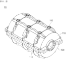
- the load break switch 1 according to an exemplary embodiment of the present invention will be described with reference to FIGS. 1 to 16 .
- the direction of rotation of each component will be understood with reference to FIGS. 4 and 5 .
- the load break switch 1 may switch on and off the rated current of the electrical circuit. That is, the load break switch 1 may allow or block energization state between an external power source and a load. To this end, the load break switch 1 is energizably connected to an external power source and a load. In other words, the external power source and the load are energizably connected by the load break switch 1.
- the switching on/off of the load break switch 1 may be operated manually or automatically. To this end, a separate operation unit may be coupled to the load break switch 1.
- the configuration of the load break switch 1 according to an exemplary embodiment of the present invention will be described with reference to the attached drawings, but a frame unit 10, a fixing part 20, a switch unit 30, a rotation shaft 40, a puffer guide 50, and an arc chute 60 will be described in separate sections.
- the load break switch 1 may be energizably connected to an external power source and a load, respectively, to allow or block energization state between the power source and the load.
- the load break switch 1 has a fixed terminal part 320 and a movable terminal part 330 that come into contact with or are separated from each other, and allows or blocks energization state between an external power source and a load.
- the load break switch 1 is coupled to a handle.
- the user may manually operate the handle whether to switch the load break switch 1 on/off.
- the switching on/off may be controlled by rotating the handle.
- an operation unit is attached to the load break switch 1.
- the operation unit switches on or off the electrical circuit between an external power source and a load under certain conditions. That is, whether to switch on/off the load break switch 1 may be automatically controlled by the operation unit.
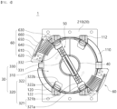
- the load break switch 1 includes a frame unit 10, a fixing part 20, a switch unit 30, a rotation shaft 40, a puffer guide 50, and an arc chute 60.
- the frame unit 10 forms the exterior of the load break switch 1.
- the outer circumference of the frame unit 10 is formed in a shape corresponding to the arc chute 60.
- the frame unit 10 is formed in a cylindrical shape.
- the shape of the frame unit 10 is not limited to the illustrated embodiment, and may be formed in various structures capable of accommodating various devices therein.
- a through hole capable of accommodating the fixed terminal part 320 is formed on the outer circumference of the frame unit 10.
- the upper and lower outer circumferential surfaces of the frame unit 10 are formed with through holes in the up-down direction to accommodate the fixed terminal part 320.
- the frame unit 10 has a space formed therein to accommodate various devices. Various devices performing a function of applying or blocking electric current transferred from the outside by the load break switch 1 may be accommodated in the space.
- the switch unit 30, the rotation shaft 40, and the puffer guide 50 are accommodated in the space.
- the rotation shaft 40 coupled to the puffer guide 50 is through-coupled to the frame unit 10.
- the rotation shaft 40 is through-coupled to the central portion of the frame unit 10 in the front-rear direction.
- the rotation shaft 40 is positioned in a straight line with the central axis of the frame unit 10.
- the gas inside the frame unit 10 may be compressed instantaneously by the pressure generated when the rotation shaft 40 rotates.
- the gas passes through the puffer guide 50 and moves in the opposite direction.
- the gas may pass through the puffer guide 50 at high speed.
- the fixing part 20 and the arc chute 60 are fixed and connected to the outside of the frame unit 10.
- the fixing part 20 is coupled to the rear side of the frame unit 10
- the arc chute 60 is coupled to the outer circumference of the frame unit 10.
- the frame unit 10 may be formed of an insulating material.
- the frame unit 10 may be formed of a synthetic resin material.
- the inside and outside of the frame unit 10 can be prevented from being arbitrarily energized. That is, the arc, which is a flow of electrons, can be prevented from randomly leaking out of the frame unit 10.
- the frame unit 10 may be formed of a material having high pressure resistance and high heat resistance. Thus, burnout to the frame unit 10 caused by an arc, which is a high-temperature and high-pressure electron flow, can be prevented.
- the frame unit 10 includes an upper frame 110 and a lower frame 120.
- the upper frame 110 forms the upper exterior of the load break switch 1.
- the upper frame 110 is formed in a semi-cylindrical shape. Specifically, the upper frame 110 has a semi-cylindrical shape with a curved surface portion facing upward. In this case, the outer circumference of the upper frame 110 is formed in a shape corresponding to the arc chute 60.
- the arc chute 60 is closely coupled to the outer circumferential surface of the upper frame 110.
- an upper fastening wing part 111 may be formed on the outer circumference of the upper frame 110. That is, the upper fastening wing part 111 is closely coupled to the arc chute 60.
- the upper fastening wing part 111 is disposed adjacent to the arc chute 60 and is inserted into and coupled to the arc chute 60.
- the upper fastening wing part 111 is formed in a plate shape.
- the upper fastening wing part 111 is formed to extend from a circular arc limited by any two points on the outer circumferential surface of the upper frame 110 toward the radially outer side of the upper frame 110. That is, the upper fastening wing part 111 is formed to protrude radially outward of the frame unit 10 from the outer circumferential surface of the upper frame 110.
- the upper fastening wing part 111 may be formed in a shape corresponding to a fastening groove 612 of the arc chute 60 to be described later.
- An upper fastening wing hole 111a is formed in the upper fastening wing part 111.
- the upper fastening wing hole 111a functions as a passage for a coupling member 620 of the arc chute 60.
- the coupling member 620 of the arc chute 60 passes through the upper fastening wing hole 111a and is coupled to the upper fastening wing part 111. That is, the coupling member 620 of the arc chute 60 is through-coupled to the upper fastening wing hole 111a.
- the coupling may be a bolt coupling method.
- the upper fastening wing hole 111a may be formed by extending a predetermined cross-section in one direction.
- the predetermined cross-section may be changed according to the coupling member 620 of the arc chute 60.
- the upper fastening wing hole 111a is formed by extending a circular cross-section in the front-rear direction.
- an upper fixed terminal accommodation part 112 that can accommodate the fixed terminal part 320 is formed to protrude from the outer circumference of the upper frame 110.
- the upper fixed terminal accommodation part 112 accommodates the fixed terminal part 320 so that the fixed terminal part 320 communicates with the external and internal spaces of the frame unit 10.
- a space for accommodating the fixed terminal part 320 is formed inside the upper fixed terminal accommodation part 112. Specifically, a fixed contact terminal is accommodated in the space. That is, the fixed contact terminal is through-coupled to the upper fixed terminal accommodation part 112.
- the upper fixed terminal accommodation part 112 is formed in a pillar shape with a hollow formed therein. In the illustrated embodiment, the upper fixed terminal accommodation part 112 extends upward from the upper outer circumferential surface of the upper frame 110.
- the upper fixed terminal accommodation part 112 is disposed to surround the fixed terminal part 320. That is, the fixed terminal part 320 is surrounded by the upper fixed terminal accommodation part 112.
- a plurality of upper fixed terminal accommodation part 112 may be provided.
- the number of upper fixed terminal accommodation parts 112 is the same as the number of fixed terminal parts 320 coupled to the upper frame 110.
- three pairs of upper fixed terminal accommodation parts 112 are arranged side by side in the front-rear direction.
- the number of the upper fixed terminal accommodation parts 112 may be determined according to the type of power system provided with the load break switch 1 of the present invention.
- the load break switch 1 is provided in a power system using a three-phase circuit of R, S, and T phases. Accordingly, three pairs of upper fixed terminal accommodation parts 112 are also provided in accordance with the three-phase circuit.
- a lower frame 120 is coupled to the lower side of the upper frame 110.
- the lower frame 120 forms the lower exterior of the load break switch 1.
- the lower frame 120 disposed adjacent to the upper frame 110. In addition, the lower frame 120 is disposed below the upper frame 110.
- the lower frame 120 is symmetrical to the upper frame 110 with respect to the rotation shaft 40.
- the upper frame 110 and the lower frame 120 are arranged to be up-down symmetrical with respect to the rotation shaft 40.
- the lower frame 120 is formed in a semi-cylindrical shape. Specifically, the lower frame 120 has a semi-cylindrical shape with a curved surface portion facing downward. In this case, the outer circumference of the lower frame 120 is formed in a shape corresponding to the arc chute 60.
- the upper end of the lower frame 120 is in contact with the lower end of the upper frame 110.
- the upper end of the lower frame 120 is formed in a shape corresponding to the lower end of the upper frame 110.
- the arc chute 60 is closely coupled to the outer circumferential surface of the lower frame 120.
- a lower fastening wing part 121 may be formed on the outer circumference of the lower frame 120. That is, the lower fastening wing part 121 is closely coupled to the arc chute 60.
- a lower fastening wing hole 121a is formed in the lower fastening wing part 121.
- the lower fastening wing part 121 and the lower fastening wing hole 121a correspond in function and structure to the upper fastening wing part 111 and the upper fastening wing hole 111a of the upper frame 110, respectively. Therefore, overlapping descriptions thereof will be omitted.
- a lower fixed terminal accommodation part 122 that can accommodate the fixed terminal part 320 is formed to protrude from the outer circumference of the lower frame 120.
- the lower fixed terminal accommodation part 122 extends downward from the lower outer circumferential surface of the lower frame 120.
- the lower fixed terminal accommodation part 122 corresponds in function and structure to the upper fixed terminal accommodation part 112 of the upper frame 110. Therefore, overlapping descriptions thereof will be omitted.
- the fixing part 20 firmly installs the frame unit 10 to the main body of the ring main unit, distribution board, etc.
- the fixing part 20 is disposed adjacent to the frame unit 10. In the illustrated embodiment, the fixing part 20 is disposed at the rear side of the frame unit 10.
- the fixing part 20 is disposed between the frame unit 10 and a specific member (not shown) in which the load break switch 1 is installed, and is coupled to the frame unit 10 and the specific member, respectively. That is, the frame unit 10 and the specific member may be coupled by the fixing part 20.
- the load break switch 1 may be operated in a state in which the frame unit 10 is coupled to the specific member without separated from the specific member.
- the fixing part 20 may be formed of a highly rigid material.
- the fixing part 20 may be formed of a metal material. Therefore, damage to the fixing part 20 and separation of the frame unit 10 due to an external impact may be prevented.
- the fixing part 20 includes a fixing plate 210 and a support fixture 220.
- the fixing plate 210 is a member to which the fixing part 20 is directly coupled to the specific member.
- the fixing plate 210 is formed on one side of the fixing part 20 opposite to the frame unit 10. In the illustrated embodiment, the fixing plate 210 is formed on the rear side of the fixing plate.
- the fixing plate 210 is formed in a plate shape. In an embodiment, a through hole may be formed in the central portion of the fixing plate 210. Therefore, the fixing plate 210 may be lighter.
- the fixing plate 210 is formed in a quadrangular plate shape having a through hole formed in the central portion thereof.
- the central point of the fixing plate 210 is positioned on an extension line of the center line of the frame unit 10.
- a fixing hole 211 may be formed through the fixing plate 210.
- a member for coupling the specific member and the fixing plate 210 may be through-coupled to the fixing hole 211.
- a through hole communicating with the fixing hole 211 is formed in the specific member.
- a support fixture 220 is disposed between the fixing plate 210 and the frame unit 10.
- the support fixture 220 is disposed between the fixing plate 210 and the frame unit 10, and is coupled to the fixing plate and the frame unit 10, respectively. That is, the fixing plate and the frame unit 10 may be coupled to each other through the support fixture 220. Therefore, the frame unit 10 may be spaced apart from the fixing plate 210.
- the support fixture 220 is coupled to one surface of the fixing plate 210 facing the frame unit 10.
- the support fixture 220 is coupled to one side of the frame unit 10 facing the support fixture 220.
- the coupling may be a bolt coupling method.
- the support fixture 220 extends in a direction toward the frame unit 10 and the fixing plate 210. In the illustrated embodiment, the support fixture 220 extends in the front-rear direction.
- a plurality of support fixtures 220 may be provided.
- the plurality of support fixtures 220 are arranged such that their central points are the same as the central point of the fixing plate 210.
- the switch unit 30 is accommodated in the inner space of the frame unit 10 to allow or block the electric current energization. Specifically, the switch unit 30 allows the electric current energization by bringing the fixed contact 321b, 322b and the movable contact 332 into contact, or blocks the electric current energization by bringing the fixed contact 321b, 322b and the movable contact 332 apart.
- a plurality of switch units 30 may be provided. In the illustrated embodiment, three switch units 30 are arranged side by side in the front-rear direction.
- the number of the switch units 30 may be determined according to the type of power system provided with the load break switch 1 of the present invention.
- the load break switch 1 is provided in a power system using a three-phase circuit of R, S, and T phases, three switch units 30 may also be provided in accordance with the three-phase circuit.
- the switch unit 30 includes an arc chamber 310, a fixed terminal part 320, and a movable terminal part 330.
- the arc chamber 310 may also be referred to as an "arc extinguishing unit".
- the arc chamber 310 extinguishes an arc generated when the fixed contact 321b, 322b and the movable contact 332 are spaced apart from each other.
- the arc chamber 310 forms a space capable of extinguishing an arc therein.
- the gas inside the space may be compressed instantaneously by the pressure generated when the movable terminal part 330 moves.
- the gas may flow in a direction opposite to the rotation direction while passing through the puffer guide 50.
- the gas flows through the puffer guide 50 at high speed, and an arc extinguishing operation may be performed.
- the arc chamber 310 hermetically accommodates the fixed terminal part 320 and the movable terminal part 330. That is, the fixed terminal part 320 and the movable terminal part 330 are accommodated inside the arc chamber 310. Therefore, the arc generated by the separation of the fixed contact 321b, 322b and the movable contact 332 is not arbitrarily discharged to the outside of the arc chamber 310.
- the fixed terminal part 320 is energizably connected to an external power source or a load.
- the load break switch 1 may be energizably connected to an external power source or a load.
- a portion of the fixed terminal part 320 is accommodated inside the arc chamber 310.
- the fixed terminal part 320 may be formed of a conductive material.
- the fixed terminal part 320 may be formed of copper (Cu), silver (Ag), or the like.
- the fixed terminal part 320 is accommodated in the internal space of the frame unit 10, so that energization between the inside and outside of the load break switch 1 can be applied or blocked. Specifically, the fixed terminal part 320 is in contact with or spaced apart from the movable terminal part 330 to apply or block energization between the inside and outside of the load break switch 1.
- the fixed terminal part 320 is coupled to the fixed terminal accommodation part 112, 122 of the frame unit 10.
- the fixed terminal part 320 is surrounded by the fixed terminal accommodation part 112, 122 and seals the fixed terminal accommodation part 112, 122. That is, the movement of the material through the fixed terminal accommodation part 112, 122 is blocked by the fixed terminal part 320.
- the fixed terminal part 320 is not moved in the internal space of the frame unit 10. Thus, the contact and separation of the fixed terminal part 320 and the movable terminal part 330 are achieved by the movement of the movable terminal part 330.
- the remaining portion of the fixed terminal part 320 except for the above portion is exposed to the outside of the frame unit 10.
- the remaining portion may be energizably connected to an external power source or a load by a conducting wire member (not shown) or the like.
- a plurality of fixed terminal parts 320 may be provided.
- the number of fixed terminal parts 320 is the same as the number of fixed terminal accommodation parts 112, 122 provided in the frame unit 10.
- four fixed terminal parts 320 are formed as one group, and three groups of fixed terminal parts 320 are arranged side by side in the front-rear direction.
- the two fixed terminal parts 320 facing each other with the rotation shaft 40 interposed between them are arranged to be point-symmetric with respect to the central axis of the rotation shaft 40.
- the two fixed terminal parts 320 facing each other with the rotation shaft 40 interposed therebetween may be energizably connected to each other.
- the connection is formed by contacting the movable terminal part 330 with the two fixed terminal parts 320, respectively.
- the fixed terminal part 320 includes a first fixed terminal part 321 and a second fixed terminal part 322.
- the first fixed terminal part 321 is energizably connected to an external power source and a load, or energizably connected to a ground wire.
- the second fixed terminal part 322 is energizably connected to a ground wire, or energizably connected to an external power source and a load.
- the movable terminal part 330 may be moved and may be in contact with or spaced apart from the first fixed terminal part 321 or the second fixed terminal part 322. However, the movable terminal part 330 cannot simultaneously contact the first fixed terminal part 321 and the second fixed terminal part 322, and may contact only one of the first fixed terminal part 321 and the second fixed terminal part 322.
- the movable terminal part 330 may be rotated in a direction toward the fixed terminal part 320 or away from the fixed terminal part 320.
- the first fixed terminal part 321 may be energizably connected to an external power source and a load
- the second fixed terminal part 322 may be energizably connected to a ground wire.
- the movable terminal part 330 when the movable terminal part 330 contacts the first fixed terminal part 321, energization between an external power source and a load may be applied. In addition, when the movable terminal part 330 contacts the second fixed terminal part 322, the movable terminal part 330 is energizably connected to the ground wire, and energization between the external power source and the load is cut off.
- the first fixed terminal part 321 includes a first fixed contact terminal 321a and a first fixed contact 321b.
- the first fixed contact terminal 321a is energizably connected to an external power source or a load.
- a portion of the first fixed contact terminal 321a is accommodated in the inner space of the frame unit 10, and the remaining portion is exposed to the outside of the frame unit 10. Specifically, a portion of the first fixed contact terminal 321a is surrounded by the fixed terminal accommodation part 112, 122.
- a plurality of first fixed contact terminals 321a may be provided. In the illustrated embodiment, a total of twelve first fixed contact terminals 321a are provided, six on the upper side and six on the lower side of the frame unit 10.
- the first fixed contact terminal 321a may have a cylindrical shape bent and extending in a direction toward the rotation shaft 40.
- the first fixed contact 321b is formed at one end of the first fixed contact terminal 321a facing the rotation shaft 40.
- the first fixed contact 321b is disposed adjacent to the first fixed contact terminal 321a.
- the first fixed contact 321b is energizably connected to the first fixed contact terminal 321a.
- the first fixed contact 321b may be in contact with or spaced apart from the movable contact 332. Accordingly, the load break switch 1 may be energized or cut off from an external power source or a load.
- the first fixed contact 321b may be integrally formed with the first fixed contact terminal 321a.
- the second fixed terminal part 322 is disposed to be spaced apart from the first fixed terminal part 321.
- the second fixed terminal part 322 is energizably connected to a member that is not connected to the first fixed terminal part 321 among an external power source, a load, and a ground wire. That is, when the first fixed terminal part 321 is energizably connected to an external power source and a load, the second fixed terminal part 322 is energizably connected to a ground wire.
- the second fixed terminal part 322 includes a second fixed contact terminal 322a and a second fixed contact 322b.
- the second fixed contact terminal 322a and the second fixed contact 322b correspond in function and structure to the first fixed contact terminal 321a and the first fixed contact 321b. Therefore, overlapping descriptions thereof will be omitted.
- the movable terminal part 330 is energizably connected to or separated from the fixed terminal part 320. Through the movable terminal part 330, a plurality of fixed terminal parts 320 may be energizably connected to each other. As a result, the load break switch 1 can be energizably connected to an external power source or a load.
- the movable terminal part 330 is accommodated in the inner space of the frame unit 10.
- the movable terminal part 330 is rotatably coupled to the internal space of the frame unit 10.
- the movable terminal part 330 is coupled to the rotation shaft 40. When the rotation shaft 40 is rotated, the movable terminal part 330 may also be rotated together with the rotation shaft 40.
- a portion of the movable terminal part 330 is accommodated in the puffer guide 50.
- a plurality of movable terminal part 330 may be provided.
- the load break switch 1 is provided with three pairs of movable terminal parts 330.
- the three pairs of movable terminal parts 330 are arranged side by side in the front-rear direction.
- the plurality of movable terminal parts 330 may be energizably in contact with or spaced apart from the plurality of fixed terminal parts 320, respectively. That is, the movable terminal part 330 may be rotated to contact the fixed terminal part 320 or may be rotated to be spaced apart from the fixed terminal part 320. The contact and separation may be achieved according to the rotation of the rotation shaft 40 connected to the movable terminal part 330.
- the movable terminal part 330 contacts the fixed terminal part 320 connected to a ground wire, the movable terminal part 330 is energizably connected to the ground wire, and energization between the external power source and the load is cut off.
- the movable terminal part 330 may be formed of a conductive material.
- the movable terminal part 330 may be formed of copper, silver, or the like.
- the movable terminal part 330 includes a movable contact terminal 331 and a movable contact 332.
- the movable contact terminal 331 is directly coupled to the rotation shaft 40 and is rotated together with the rotation shaft 40.
- the movable contact terminal 331 may be rotated clockwise or counterclockwise by the rotation shaft 40.
- the movable contact terminal 331 is arranged such that its central point is the same as the central point of the rotation shaft 40.
- the movable contact terminal 331 is formed in a rod shape extending in a predetermined direction.
- the predetermined direction may be a radial direction of the rotation shaft 40.
- the movable terminal part 330 is bent and extended toward the fixed terminal part 320.
- both ends of the movable contact terminal 331 are divided into two parts in the radial direction of the rotation shaft 40.
- a movable contact 332 is formed at each end.
- the movable contact 332 is energizably connected to the movable contact terminal 331.
- the movable contact 332 is in contact with or separated from the fixed contact 321b, 322b. Accordingly, the load break switch 1 may be energized or cut off from an external power source or a load.
- the movable contact 332 is located at both ends of the movable contact terminal 331. That is, the movable contact 332 is located radially outward with respect to the rotation shaft 40.
- the movable contact 332 is disposed to be surrounded by the puffer guide 50. In another embodiment, the movable contact 332 is disposed radially more outward from the puffer guide 50 with respect to the rotation shaft 40. That is, in the above embodiment, the movable contact 332 is not surrounded by the puffer guide 50, but is exposed to the outside of the puffer guide 50.
- a plurality of movable contacts 332 may be provided.
- two movable contacts 332 are located at both ends of the movable contact terminal 331, respectively. That is, the movable contact terminal 331 includes a total of four movable contacts 332.
- the movable contact 332 When the rotation shaft 40 rotates, the movable contact 332 is rotated together with the rotation shaft 40.
- the movable contact 332 is accommodated in the inner space of the frame unit 10 to be rotatable with respect to the rotation axis of the rotation shaft 40.
- the movable contact 332 may be integrally formed with the movable contact terminal 331.
- the rotation shaft 40 is connected to the movable terminal part 330 and rotates together with the movable terminal part 330.
- the movable terminal part 330 may be energizably in contact with or spaced apart from the fixed terminal part 320.
- the rotation shaft 40 is rotatably coupled to the frame unit 10. Specifically, the rotation shaft 40 is rotatably accommodated in the inner space of the frame unit 10.
- the rotation shaft 40 is connected to the movable terminal part 330.
- a plurality of movable terminal parts 330 are through-coupled to the rotation shaft 40.
- the rotation shaft 40 is energizably connected to the movable terminal part 330. Therefore, the electric current flowing into the load break switch 1 through the fixed terminal part 320 may proceed toward the other fixed terminal part 320 through the movable terminal part 330 and the rotation shaft 40.
- the puffer guide 50 is coupled to one side of the rotation shaft 40.
- the inner space of the puffer guide 50 and the inner space of the rotation shaft 40 communicate with each other.
- rotation shaft 40 may be connected to a handle (not shown) or an operation unit (not shown).
- the rotation of the rotation shaft 40 may be manually operated by the handle or automatically operated by the operation unit.
- the rotation shaft 40 rotates clockwise or counterclockwise with respect to the central axis.
- the rotation shaft 40 rotates and rotates the movable terminal part 330. That is, the movable terminal part 330 may be rotated by the rotation shaft 40 in a direction toward the fixed terminal part 320 or away from the fixed terminal part 320.
- the rotation shaft 40 is formed in a cylindrical shape.
- the central point of the rotation shaft 40 is positioned to be the same as the central point of the movable terminal part 330.
- a plurality of rotation shafts 40 may be provided.
- the number of the rotation shafts 40 is equal to the number of the movable terminal parts 330.
- three rotation shafts 40 are arranged side by side in the front-rear direction.
- the number of the rotation shafts 40 may be determined according to the type of power system provided with the load break switch 1 of the present invention.
- the load break switch 1 is provided in a power system using a three-phase circuit of R, S, and T phases, three rotation shafts 40 may also be provided in accordance with the three-phase circuit.
- the rotation shaft 40 includes a pillar portion 410 and an uneven portion 420.
- the pillar portion 410 forms the exterior of the rotation shaft 40.
- the pillar portion 410 is through-coupled to the movable terminal part 330 and rotates together with the movable terminal part 330.
- the pillar portion 410 is disposed between two facing puffer guides 50, and is coupled to the two puffer guides 50, respectively.
- the pillar portion 410 is formed in a cylindrical shape. In the illustrated embodiment, a hollow is formed in the central portion of the pillar portion 410.
- An uneven portion 420 are formed at both ends of the pillar portion 410.
- the uneven portion 420 more firmly couples two adjacent rotation shafts 40.
- the uneven portion 420 of one of the two adjacent rotation shafts 40 is placed adjacent to the uneven portion 420 of the other rotation shaft 40.
- the uneven portions 420 of the two rotation shafts 40 are formed in shapes corresponding to each other. Accordingly, the uneven portions 420 of the two rotation shafts 40 may be engaged and coupled to each other. Accordingly, when one rotation shaft 40 rotates, the remaining rotation shaft 40 may also rotate.
- the puffer guide 50 may disperse and extinguish the arc by narrowing the flow path of the gas, whose pressure increases as the movable terminal part 330 rotates.
- the puffer guide 50 is accommodated in the inner space of the frame unit 10.
- the puffer guide 50 is coupled to one side of the rotation shaft 40.
- the puffer guide 50 extends radially outward of the rotation shaft 40 from the one side of the rotation shaft 40.
- the puffer guide 50 may be coupled to the rotation shaft 40 by welding.
- a plurality of puffer guides 50 may be provided.
- two puffer guides 50 may be provided.
- the two puffer guides 50 are disposed to face each other with the rotation shaft 40 interposed therebetween. That is, the two puffer guides 50 are disposed to be point-symmetric with respect to the rotation shaft 40.
- the puffer guide 50 is formed to surround the movable terminal part 330.
- one side of the puffer guide 50 facing radially outward of the rotation shaft 40 is open. Accordingly, an arc generated when the movable terminal part 330 rotates may be guided to the arc chute 60.
- the puffer guide 50 coupled to the rotation shaft 40 rotates together with the rotation shaft 40 when the rotation shaft 40 rotates. That is, the puffer guide 50 may be rotated clockwise or counterclockwise. At this time, the puffer guide 50 rotates in a direction toward the arc chute 60 or away from the arc chute 60, but does not collide with the arc grid of the arc chute 60.
- the gas inside the arc chamber 310 is compressed and the pressure thereof is increased.
- the gas passes through the puffer guide 50 and flows in a direction opposite to the rotation. In the flow process, the gas passes through the puffer guide 50 at high speed, and an arc extinguishing operation may be performed.
- the puffer guide 50 includes a housing part 510 and an insertion part 520.
- the housing part 510 forms the exterior of the puffer guide 50.
- the housing part 510 supports the movable terminal part 330 in the front, rear, and left and right directions.
- the housing part 510 is disposed adjacent to the rotation shaft 40. In addition, the housing part 510 is directly coupled to the rotation shaft 40. In an embodiment, the housing part 510 may be coupled to the rotation shaft 40 by welding.
- the housing part 510 is formed in a pillar shape with a hollow formed therein. Both sides of the housing part 510 facing the radial direction of the rotation shaft 40 are open.
- the housing part 510 may be divided into a housing front part, a housing rear part 511, and a housing side part based on the rotation direction.
- the insertion part 520 is coupled to one end of the housing part 510 facing radially outward of the rotation shaft 40.
- the insertion part 520 is coupled to the housing part 510 in a sliding manner.
- the insertion part 520 coupled to the housing part 510 may be prevented from being arbitrarily detached by a locking sill (not shown) formed in the housing part 510.
- the insertion part 520 When the rotation shaft 40 and the housing part 510 are rotated, the insertion part 520 is rotated together with the housing part 510. During the rotation process, the insertion part 520 does not collide with the arc grid of the arc chute 60. That is, the insertion part 520 is disposed to be spaced apart from the arc grid.
- the distance between one end of the insertion part 520 facing radially outward of the rotation shaft 40 and the rotation shaft 40 is formed to be smaller than the distance between one end of the arc grid facing radially inward of the rotation shaft 40 and the rotation shaft 40. That is, the insertion part 520 is disposed radially more inward with respect to the frame unit 10 as compared with the arc grid.
- the insertion part 520 may be divided into an insertion front part, an insertion rear part 521, and an insertion side part based on the rotation direction.
- the insertion rear part 521 is inserted into the housing rear part 511.
- the gas inside the frame unit 10 is compressed when the rotation shaft 40 rotates and flows through the insertion rear part 521 with increased pressure.
- a rear recessed portion 521a for narrowing the flow path of the gas may be formed in the insertion rear part 521.
- the rear recessed portion 521a performs a function of dispersing and extinguishing the arc by narrowing the flow path of the gas inside the frame unit 10.
- the rear recessed portion 521a is formed by being recessed from one side facing radially outward of the rotation shaft 40 in a direction toward the rotation shaft 40.
- the rear recessed portion 521a is formed with a predetermined cross-section extending in the thickness direction of the insertion part 520.
- the predetermined cross-section is a trapezoid.
- the arc chute 60 extends the length of the arc that occurs when the electric current is switched on/off, cooling and extinguishing the arc.
- the arc chute 60 is disposed adjacent to the outer circumference of the frame unit 10. Specifically, the arc chute 60 is in close contact with the outer circumference of the frame unit 10.
- the arc chute 60 is coupled to the frame unit 10.
- the arc chute 60 is coupled to the fastening wing parts 111 and 121 of the frame unit 10.
- the fastening wing parts 111 and 121 are inserted into the fastening groove 612 of the arc chute 60.
- a portion of the arc chute 60 is inserted into and coupled to the inner space of the frame unit 10 and the arc chamber 310.
- the arc chute 60 is formed in a shape corresponding to the outer circumference of the frame unit 10.
- the arc chute 60 is formed in a curved shape to correspond to the cylindrical frame unit 10, and is formed to extend along the circumferential direction of the frame unit 10.
- the arc chute 60 may be easily installed in the rotary load break switch 1.
- the radius of curvature of the arc chute 60 may be the same as the radius of curvature of the frame unit 10. Accordingly, the arc chute 60 may be in close contact with the outer circumferential surface of the frame unit 10.
- a plurality of arc chutes 60 may be provided.
- two arc chutes 60 are formed as a pair. This is to respond to an arc generated when the movable terminal part 330 in contact with the two fixed contacts 321b and 322b is simultaneously separated from the two fixed contacts 321b and 322b.
- the two arc chutes 60 facing each other with the rotation shaft 40 interposed between them are arranged to be point-symmetric with respect to the central axis of the rotation shaft 40. Accordingly, the arc extinguishing capability of the arc chute 60 may be maximized.
- the arc chute 60 is not limited to the illustrated form and may be variously formed. In an embodiment, three pairs of arc chutes 60 may be provided. In the above embodiment, the three pairs of arc chutes 60 may be arranged side by side in the front-rear direction.
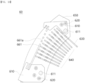
- the arc chute 60 includes a fastening part 610, a coupling member 620, an arc runner 630, an arc grid part 640, a side cover part 650, and a top cover part 660.
- the fastening part 610 is a member to which the arc chute 60 is directly coupled to the frame unit 10.
- the fastening part 610 is disposed adjacent to the outer circumference of the frame unit 10. In addition, the fastening part 610 is coupled to the fastening wing parts 111 and 121 of the frame unit 10.
- the fastening part 610 overlaps the fastening wing parts 111 and 121 in a predetermined direction.
- the predetermined direction is an axial direction of the frame unit 10.
- the fastening part 610 is disposed between a plurality of side cover parts 650.
- the fastening part 610 is disposed between two side cover parts 650 and coupled to each side cover part 650.
- the fastening part 610 is disposed so that the front and rear sides thereof are covered by the side cover part 650.
- a plurality of fastening parts 610 may be provided.
- the number of fastening parts 610 is the same as the number of fastening wing parts 111 and 121 of the frame unit 10.
- the arc chute 60 is provided with two fastening parts 610.
- the arc runner 630, the arc grid part 640, and the top cover part 660 are disposed between the two fastening parts 610.
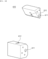
- the fastening part 610 may be provided with a fastening hole 611 communicating with a through hole of the side cover part 650.
- the fastening hole 611 is through-formed in the axial direction of the frame unit 10.
- a fastening groove 612 is recessed in the fastening part 610.
- the fastening groove 612 is formed to be recessed radially outward of the frame unit 10 from one surface in contact with the outer circumferential surface of the frame unit 10. In addition, the fastening groove 612 is formed to extend in the radial direction of the frame unit 10.
- the fastening groove 612 is formed in a shape corresponding to the fastening wing part 111, 121. This assists in a more robust coupling between the fastening groove 612 and the fastening wing part 111, 121.
- the fastening groove 612 is coupled to the fastening wing parts 111 and 121 of the frame unit 10. Specifically, the fastening wing parts 111 and 121 are inserted into and coupled to the fastening groove 612. To this end, it is preferable that the thickness of the fastening groove 612 is greater than the thickness of the fastening wing part 111, 121.
- the fastening hole 611 is formed by penetrating the fastening part 610 in a predetermined direction.
- the fastening hole 611 is formed through the fastening groove 612.
- the predetermined direction is an axial direction of the frame unit 10.
- the fastening hole 611 is positioned in a straight line with the cover coupling hole 651 of the side cover part 650 and the fastening wing holes 111a and 121a of the fastening wing parts 111 and 121.
- the coupling member 620 passes through the fastening part 610 and the fastening wing part of the frame unit 10, and further strengthens the coupling between the fastening part 610 and the fastening wing part 111, 121. Specifically, the coupling member 620 passes through the fastening hole 611 of the fastening part 610, the cover coupling hole 651 of the side cover part 650, and the fastening wing holes 111a and 121a of the fastening wing parts 111 and 121.
- the coupling member 620 is not limited to the illustrated form, and may be formed in various forms. In an embodiment, the coupling member 620 may be coupled to the arc chute 60 and the frame unit 10 by a bolt coupling method.
- the coupling member 620 may be formed of a highly rigid material.
- the coupling member 620 may be formed of a metal material.
- the arc runner 630 and the arc grid part 640 are disposed between the two coupling members 620.
- the arc runner 630 may maximize the arc guide effect of the arc chute 60.
- the arc runner 630 is disposed between the fixed terminal part 320 and the arc grid part 640. In addition, the arc runner 630 is disposed closer to the fixed terminal part 320 when compared to the arc grid part 640. In the illustrated embodiment, the arc runner 630 is disposed further to the right side with respect to the arc grid part 640.
- a portion of the arc runner 630 is in contact with the fixed terminal part 320. Accordingly, when an arc is generated, the arc may be guided toward the arc runner 630. As a result, the arc guide effect can be maximized.
- Another portion of the arc runner 630 is inserted into and fixed to the side cover part 650.
- the arc runner 630 is disposed between two side cover parts 650 to be coupled to the two side cover parts 650, respectively.
- the arc runner 630 may be formed of a conductive material.
- the arc runner 630 may be formed of a metal material.
- the runner base part 631 is disposed closer to the fixed terminal part 320 when compared to a grid base part 6411, 6421 of the arc grid part 640. In the illustrated embodiment, the runner base part 631 is disposed further to the right side with respect to the grid base part 6411, 6421.
- the runner base part 631 is formed in a plate shape. In an embodiment, the runner base part 631 is formed to extend in the width direction. That is, the width of the runner base part 631 is formed to be longer than the length. In the illustrated embodiment, the width direction is the front-rear direction, and the length direction is the up-down direction.
- the runner leg 632 is disposed adjacent to the fixed terminal part 320. However, when the puffer guide 50 rotates, the runner leg 632 passes through the rear recessed portion 521a of the puffer guide 50 and does not collide with the puffer guide 50.
- the runner leg 632 extends from the one side of the runner base part 631 toward the fixed terminal part 320. In addition, the runner leg 632 extends in the length direction. In the illustrated embodiment, the runner leg 632 extends downward from the lower side of the runner base part 631.
- a portion of the runner leg 632 in contact with the fixed terminal part 320 is bent and extended along the contact surface of the fixed terminal part 320.
- the runner leg 632 may be integrally formed with the runner base part 631.
- the runner coupling protrusion 633 is formed on the other side of the runner base part 631 facing the side cover part 650. In the illustrated embodiment, the runner coupling protrusion 633 is formed on the front side and the rear side of the runner base part 631.
- the arc grid part 640 is arranged on one side of the arc runner 630 opposite to the fixed terminal part 320.
- the arc grid part 640 is disposed between two side cover parts 650 facing each other. A portion of the arc grid part 640 is inserted into and fixed to the cover through hole 652 of the side cover part 650. That is, the arc grid part 640 is disposed adjacent to the side cover part 650.
- first arc grid 641 and the second arc grid 642 will be described with reference to FIGS. 13 to 14 .
- the first arc grid 641 may be divided into a first grid base part 6411, a first grid leg 6412, and a first grid coupling protrusion 6413.
- the first grid leg 6412 is formed on one side of the first grid base part 6411 facing radially inward of the frame unit 10.
- the first grid leg 6412 extends from the one side of the first grid base part 6411 toward the rotation shaft 40. In addition, the first grid leg 6412 extends in the length direction. In the illustrated embodiment, the first grid leg 6412 extends downward from the lower side of the first grid base part 6411.
- the first grid leg 6412 passes through the rear recessed portion 521a of the puffer guide 50 and does not collide with the puffer guide 50.
- the first grid leg 6412 may be formed in various shapes according to the shapes of the movable terminal part 330, the puffer guide 50, etc., and the driving condition of the load break switch 1.
- the first grid leg 6412 may be changed in length, shape, and distance to the neighboring second arc grid 642, and etc. according to the driving condition of the load break switch 1.
- first grid legs 6412 are provided in the first arc grid 641.
- the first grid leg 6412 is formed to be symmetrical with respect to the front-rear direction and left-right direction of first arc grid 641.
- first grid leg 6412 is not limited to the illustrated shape and may be formed in various structures.
- first grid leg 6412 may be disposed to be biased in a specific direction with respect to the first arc grid 641.
- first grid leg 6412 may be integrally formed with the first grid base part 6411.
- a first grid concave portion 6412a is formed between the two first grid legs 6412 provided in the first arc grid 641. That is, the first grid concave portion 6412a refers to a space between the two first grid legs 6412.
- the first grid concave portion 6412a forms a direct arc-guided path.
- the arc generated between the fixed terminal part 320 and the movable terminal part 330 is guided to the first grid concave portion 6412a and extinguished.
- the first grid concave portion 6412a may be formed in various shapes. The shape of the first grid concave portion 6412a is determined according to the position and shape of the first grid leg 6412.
- the first grid concave portion 6412a is formed to be symmetrical with respect to the front-rear direction and left-right direction of first arc grid 641. In an embodiment not shown, the first grid concave portion 6412a may be disposed to be biased in a specific direction with respect to the first arc grid 641.
- the first grid coupling protrusion 6413 is formed on the other side of the first grid base part 6411 facing the side cover part 650. In the illustrated embodiment, the first grid coupling protrusion 6413 is formed on the front side and the rear side of the first grid base part 6411.
- the first grid coupling protrusion 6413 fixes the first arc grid 641 to the side cover part 650.
- the first grid coupling protrusion 6413 is inserted into the cover through hole 652 of the side cover part 650.
- the first grid coupling protrusion 6413 is formed to extend from the other side of the first grid base part 6411 toward the side cover part 650. In the illustrated embodiment, the first grid coupling protrusion 6413 extends from the front side or rear side of the first grid base part 6411 toward the front side or rear side.
- the first grid coupling protrusion 6413 may be integrally formed with the first grid base part 6411.
- the second arc grid 642 is disposed on one side of the first arc grid 641.
- the second arc grid 642 may be divided into a second grid base part 6421, a second grid leg 6422, and a second grid coupling protrusion 6423.
- the second grid base part 6421, the second grid leg 6422, and the second grid coupling protrusion 6423 correspond in function and structure to the first grid base part 6411, the first grid leg 6412, and the first grid coupling protrusion 6413 of the first arc grid 641.
- a second grid hole 6421a formed in the second grid base part 6421 and a second grid concave portion 6422a formed in the second grid leg 6422 also correspond in function and structure to the first grid hole 6411a and the first grid concave portion 6412a.
- the second grid hole 6421a formed in the second grid base part 6421 does not overlap in the arrangement direction of the first grid hole 6411a and the arc grid part 640. That is, grid holes 6411a and 6421a are formed at different portions of the first arc grid 641 and the second arc grid 642.
- the shape of the arc grid part 640 is not limited to the above description, and may be formed in various structures capable of extinguishing the arc.
- the arc runner 630 and the arc grid part 640 are disposed between two side cover parts 650.
- the side cover part 650 forms the front side and rear side exterior of the arc chute 60.
- the side cover part 650 supports the fastening part 610, the arc runner 630, the arc grid part 640, and the top cover part 660 in both directions.
- the side cover part 650 supports the fastening part 610, the arc runner 630, the arc grid part 640, and the top cover part 660 in the front-rear direction.
- the side cover part 650 is disposed adjacent to the frame unit 10. Specifically, the side cover part 650 is disposed adjacent to the outer circumference of the frame unit 10 and the fixed terminal accommodation part 112, 122.
- a plurality of side cover parts 650 may be provided.
- the arc chute 60 is provided with two side cover parts 650.
- the two side cover parts 650 overlap in the axial direction of the frame unit 10.
- the fastening part 610, the arc runner 630, the arc grid part 640, and the top cover part 660 is disposed between the two side cover parts 650 facing each other.
- the runner coupling protrusion 633 of the arc runner 630 and the grid coupling protrusion 6413, 6423 of the arc grid part 640 are inserted into the side cover part 650.
- the two side cover parts 650 are coupled to both sides of the arc runner 630 and the arc grid part 640, respectively.
- the side cover part 650 may be closely coupled to the fastening part 610, the arc runner 630, the arc grid part 640, and the top cover part 660 by the coupling member 620.
- the side cover part 650 is coupled to the outer circumferential surface of the frame unit 10.
- one side of the side cover part 650 in contact with the outer circumference of the frame unit 10 may be formed in a shape corresponding to the outer circumference of the frame unit 10. Accordingly, the one side of the side cover part 650 may be more firmly close contact with the outer circumference of the frame unit 10.
- At least one side of the side cover part 650 may be formed in a curved shape.
- the side cover part 650 may be formed in a plate shape including a plurality of curves, and may extend in the circumferential direction and radial direction of the frame unit 10.
- the side cover part 650 is formed in a plate shape that is formed to extend radially outward from a predetermined circular arc. Accordingly, the side cover part 650 may be in close contact with and coupled to the rotary load break switch 1. That is, the side cover part 650 may be easily installed in the rotary load break switch 1.
- the one side and the other side of the side cover part 650 are disposed adjacent to the fixed terminal part 320.
- the right side of the side cover part 650 is disposed adjacent to the fixed terminal part 320.
- a cover coupling hole 651 and a cover through hole 652 are formed in the side cover part 650.
- the coupling member 620 is through-coupled to the cover coupling hole 651.
- a plurality of cover coupling holes 651 may be provided.
- the number of cover coupling holes 651 may be the same as the number of coupling members 620.
- the cover through hole 652 is formed at a position spaced apart from the cover coupling hole 651.
- the arc runner 630 and the arc grid part 640 are inserted into the cover through hole 652. Specifically, the runner coupling protrusion 633 of the arc runner 630 and the grid coupling protrusion 6413, 6323 of the arc grid part 640 are inserted into the cover through hole 652.
- a plurality of cover through holes 652 may be provided.
- the number of cover through holes 652 is equal to the sum of the number of runner coupling protrusions 633 and the number of grid coupling protrusions 6413, 6423 provided in the arc chute 60.
- a plurality of cover through holes 652 are arranged at regular intervals along a predetermined curve.
- the radius of curvature of the predetermined curve may be the same as the radius of curvature of the frame unit 10.
- the cover through hole 652 is formed in a shape corresponding to the runner coupling protrusion 633 and the grid coupling protrusion. In the illustrated embodiment, the cover through hole 652 is formed by extending a rectangular cross-section in the front-rear direction.
- the top cover part 660 is inserted between the two side cover parts 650 facing each other.
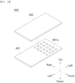
- top cover part 660 will be described with reference to FIGS. 15 to 16 .
- the top cover part 660 forms the upper exterior of the arc chute 60.
- the top cover part 660 is disposed between two side cover parts 650 to be coupled to the two side cover parts 650, respectively. In this case, the top cover part 660 crosses both ends of the side cover part 650 and blocks the upper opening of the side cover part 650. Accordingly, the top cover part 660 may block the inside and the outside of the arc chamber 310.
- the discharge of flying debris and high-temperature gas generated inside the arc chamber 310 during arc generation can be blocked by the top cover part 660. Furthermore, insulation breakdown due to the flying debris and high-temperature gas discharged to the outside of the arc chute 60 can be prevented. As a result, firing outside the arc chute 60 can be blocked.
- top cover part 660 can block one side of the space between two adjacent arc grids 641 and 642, so that the arc voltage inside the arc chute 60 can be kept constant regardless of the passage of time. Accordingly, the arc extinguishing performance of the arc chute 60 can be further improved.
- the top cover part 660 is spaced apart from the outer circumferential surface of the frame unit 10. Specifically, the top cover part 660 is disposed with the outer circumferential surface of the frame unit 10 and the arc grid part 640 interposed therebetween.
- the top cover part 660 may be formed of a flat plate extending in one direction. In the above embodiment, the top cover part 660 is formed in a plate shape crossing both ends of the two side cover parts 650.
- the top cover part 660 may be formed of a curved plate corresponding to the curve of the side cover part 650.
- top cover holes 661a and 662a are formed in a portion of the top cover part 660.
- the top cover part 660 is not limited to the illustrated structure, and may be formed in various structures.
- the top cover part 660 may be formed to seal the upper side of the side cover part 650.
- At least a portion of the top cover part 660 may be formed of an N-9 (nylon-9) material.
- one surface of the top cover part 660 facing the arc grid part 640 may be formed of an N-9 material.
- the N-9 material is a polyamide Pa6/Pa66 series, and when directly exposed to the arc, it emits hydrogen gas with excellent thermal conductivity. Accordingly, the top cover part 660 generates hydrogen gas when directly exposed to the arc and can increase the arc extinguishing cooling effect.
- a plurality of top cover parts 660 may be provided.
- the top cover part 660 includes a first top cover 661 and a second top cover 662.
- the first top cover 661 is disposed adjacent to the arc grid part 640 to preferentially block the arc passing through the arc chute 60. In the illustrated embodiment, the first top cover 661 is disposed above the arc grid part 640.
- the first top cover 661 crosses both ends of the side cover part 650 and blocks the upper opening of the side cover part 650. In addition, the first top cover 661 is spaced apart from the outer circumferential surface of the frame unit 10.
- the first top cover 661 is formed in a quadrangular flat plate shape.
- the first top cover 661 is not limited to the illustrated shape, and may be formed in various shapes.
- the first top cover 661 may be formed of a curved plate corresponding to the curve of the side cover part 650.
- a first top cover hole 661a may be formed through a portion of the first top cover 661.
- the first top cover hole 661a forms a detour path of the arc toward the first top cover 661. Accordingly, the arc can be extended and cooled more efficiently.
- a plurality of first top cover holes 661a may be provided.
- the first top cover hole 661a is formed as a circular hole and is formed at a position biased to the right with respect to the central portion of the first top cover 661. This is formed in consideration of the flow direction of air compressed by the puffer guide 50.
- the first top cover hole 661a is not limited to the illustrated shape and position, and may be formed in various structures capable of forming a detour path of the arc.
- the first top cover hole 661a may be formed as a quadrangular hole and disposed in the central portion of the first top cover 661.
- the second top cover 662 is disposed above the first top cover 661.
- the second top cover 662 secondarily blocks the flying debris and the high-temperature gas that have passed through the first cover hole of the first top cover 661. Through this, the emission of flying debris and high-temperature gas generated when an arc is generated may be prevented doubly.
- the second top cover 662 is disposed with the arc grid part 640 and the first top cover 661 interposed therebetween. In this case, the second top cover 662 is positioned radially outward of the frame unit 10 with respect to the first top cover 661. In addition, the second top cover 662 is spaced apart from the first top cover 661 at a predetermined interval.
- the second top cover 662 crosses both ends of the side cover part 650 and blocks the upper space of the first top cover 661.
- the second top cover 662 may be formed in a shape corresponding to that of the first top cover 661.
- the second top cover 662 is formed in a quadrangular flat plate shape.
- the second top cover 662 is not limited to the illustrated embodiment, and may be formed in various shapes.
- the second top cover 662 may be formed of a curved plate corresponding to the curve of the side cover part 650.
- a second top cover hole 662a is formed through a portion of the second top cover 662.
- the second top cover hole 662a forms a detour path of the arc toward the second top cover 662. Accordingly, the arc can be extended and cooled more efficiently.
- a plurality of second top cover holes 662a may be provided.
- the second top cover hole 662a is disposed so as not to overlap each other in the arrangement direction of the first top cover hole 661a, the first top cover 661, and the second top cover 662.
- the second top cover hole 662a is formed as a circular hole and is formed at a position biased to the left with respect to the central portion of the second top cover 662.
- the second top cover hole 662a is not limited to the illustrated shape and position, and may be formed in various structures capable of forming a detour path of the arc.
- the second top cover hole 662a may be formed as a quadrangular hole and disposed in the central portion of the second top cover 662.
- the second top cover 662 may be formed to seal the upper space of the first top cover 661 by omitting the second top cover hole 662a. Accordingly, the upper side of the side cover part 650 may be sealed.
- the fastening part 610, the coupling member 620, the arc runner 630, the arc grid part 640, and the side cover part 650 correspond in function and structure to the fastening part 610, the coupling member 620, the arc runner 630, the arc grid part 640, and the side cover part 650 according to the above-described embodiment.
- the top cover part 660 according to the present embodiment is different from the top cover part 660 according to the above-described embodiment in some components. Specifically, the top cover part 660 according to the present embodiment is different from the top cover part 660 according to the above-described embodiment in that a single top cover part 660 is provided in the arc chute 60.
- top cover part 660 according to the present embodiment will be described focusing on differences from the top cover part 660 according to the above-described embodiment.
- the top cover part 660 includes a first top cover 661.
- the first top cover 661 is disposed adjacent to the arc grid part 640 to preferentially block the arc passing through the arc chute 60.
- a first top cover hole 661a is formed through a portion of the first top cover 661.
- the first top cover hole 661a has the same structure and function as the first top cover hole 661a according to the above-described embodiment.
- the first top cover 661 may be formed to seal the upper side of the side cover part 650 by omitting the first top cover hole 661a.
- the arc, flying debris, high-temperature gas, and the like that have passed through the arc grid part 640 collide with the first top cover 661 and are not discharged to the outside of the arc chute 60.
- FIG. 21(a) shows the load break switch 1 before an arc A is generated
- FIG. 21(b) shows the load break switch 1 after an arc A is generated.
- the generated arc A is primarily guided toward the arc runner 630.
- the arc A guided toward the arc runner 630 is moved from the arc runner 630 toward the arc grid part 640. Specifically, the arc A is moved toward the grid concave portions 6412a and 6422a of the arc grid part 640.
- the arc A is moved along the grid concave portions 6412a and 6422a provided in the plurality of arc grid parts 640 in a direction away from the fixed terminal part 320.
- some of the arc A, the flying debris, and the high-temperature gas may flow radially outward of the frame unit 10 through the arc grid part 640.
- the arc A, the flying debris, and the high-temperature gas flowing radially outward of the frame unit 10 collide with the top cover part 660.
- the arc A, the flying debris, and the high temperature gas flowing upward of the arc grid part 640 first collide with the first top cover 661.
- Some of the arc A, the flying debris, and the high-temperature gas flowing toward the first top cover 661 flow through the first top cover hole 661a toward the second top cover 662. Some of the arc A, the flying debris, and the high temperature gas flowing toward the second top cover 662 collide with the second top cover 662, and only the remaining part passes through the second top cover hole 662a.
- the arc A, the flying debris, and the high-temperature gas flowing upward of the arc grid part 640 sequentially pass through the first top cover 661 and the second top cover 662.
- the first top cover hole 661a and the second top cover hole 662a do not overlap each other in the arrangement direction of the first top cover 661 and the second top cover 662.
- the amount of discharge of the arc A, the flying debris, and the high temperature gas may be sequentially reduced in the process of passing through the first top cover 661 and the second top cover 662.
- the arc A can be extended and cooled and extinguished as the aforementioned series of processes progress.
- embodiments may be configured by selectively combining all or some of the embodiments so that various modifications may be made thereto.
Landscapes
- Arc-Extinguishing Devices That Are Switches (AREA)
- Gas-Insulated Switchgears (AREA)
- Tumbler Switches (AREA)
Abstract
Description
- The present invention relates to an arc chute and a load break switch including the same, and more particularly, to an arc chute in which firing from the outside can be blocked and a load break switch including the same.
- A load break switch (LBS) refers to a component that opens and closes the rated current of an electrical circuit to protect the branching and division of lines and the power system. Furthermore, in general power circuits where short-circuit protection is not required, load break switches can be used instead of circuit breakers to interrupt overload currents and ground fault currents.
- A load break switch includes a fixed terminal part that is energizably connected to an external power source and a load, and a movable terminal part that can be moved toward or away from the fixed terminal part. The movable terminal part can be moved manually or automatically to contact and separate from the fixed terminal part.
- When the movable terminal part comes into contact with the fixed terminal part, the load break switch is energized with an external power source and a load. That is, when the movable terminal part comes into contact with the fixed terminal part, the load break switch supplies power to the load.
- Conversely, when the movable terminal part is separated from the fixed terminal part, the load break switch is disconnected from the external power source and the load, thereby cutting off the power supply to the load. In the above process, an arc is generated between the movable terminal part and the fixed terminal part.
- Arc refers to an electrical discharge that occurs when a voltage is formed between two electrodes placed with a gas interposed therebetween and occurs when a gas existing between the two electrodes is converted into a conducting medium.
- Since the arc is a high-temperature and high-pressure electron flow, it may delay blocking of current and cause damage to the load break switch. Therefore, rapid processing of the arc generated during the power cut-off process of the load break switch is required. This is called arc extinguishing. The load break switch includes an arc chute for arc extinguishing.
- The arc chute is a component that extinguishes arcs that occur during the process of switching and interrupting current. The arc chute extends and cools the arc, thereby extinguishing the arc.
- A typical arc chute is equipped with multiple arc grids. Each arc grid extends the arc length by directing the arc away from the fixed terminal part.
- In this case, the flying debris and high-temperature gases accompanying the arc generation can be released to the outside through the gaps between the multiple arc grids. Since the arc voltage of the arc chute gradually decreases over time, the flying debris and high-temperature gases released to the outside may cause insulation breakdown and subsequent firing.
- Therefore, the development of an arc chute capable of blocking firing from the outside and a load break switch including the same may be considered.
-
U.S. Patent Registration No. 9,653,237 - However, this type of arc chute can allow flying debris and high-temperature gases to pass between two adjacent arc plates, which can be released to the outside and cause insulation breakdown.
-
Korean Patent Registration No. 10-1977053 - However, the arc chute equipped with this type of load break switch is partially exposed to the outside and communicates with the outside space, which may cause insulation breakdown and subsequent firing phenomenon by releasing flying debris and high-temperature gases to the outside.
- (Patent Document 1)
U.S. Patent Registration No. 9,653,237 (2017. 03. 16 - (Patent Document 2)
Korean Patent Registration No. 10-1977053 (2019. 05. 03 - The present invention is directed to providing an arc chute in which firing from the outside can be blocked, and a load break switch including the same.
- The present invention is also directed to providing an arc chute in which the internal arc voltage can be kept constant, and a load break switch including the same.
- The present invention is directed to providing an arc chute capable of further improving the arc cooling effect, and a load break switch including the same.
- In order to achieve the above objects, an arc chute according to an aspect of the present invention includes an arc grid part; two side cover parts spaced apart from each other and overlapping in one direction, and respectively coupled to both sides of the arc grid part; and a top cover part that is disposed between the two side cover parts and coupled to each of the two side cover parts, and is formed in a plate shape extending across both ends of the two side cover parts.
- In addition, the top cover part may have a top cover hole formed through a portion thereof.
- In addition, the top cover part may include a plurality of top cover holes.
- In addition, the top cover part may be formed to seal one side of the side cover part.
- In addition, the top cover part may include a first top cover adjacent to the arc grid part; and a second top cover spaced apart from the first top cover and placed with the arc grid part and the first top cover interposed therebetween.
- In addition, the first top cover may have a first top cover hole formed through a portion thereof.
- In addition, the second top cover may have a second top cover hole formed through a portion thereof.
- In addition, the first top cover hole and the second top cover hole may do not overlap each other in the arrangement direction of the first top cover and the second top cover.
- In addition, the top cover part may be formed of a flat plate extending in one direction.
- In addition, at least one side of the side cover part may be formed in a curved shape, and the top cover part may be formed of a curved plate corresponding to the curve of the side cover part.
- In addition, at least a portion of the top cover part may be formed of an N-9 (nylon-9) material.
- In addition, one surface of the top cover part facing the arc grid part may be formed of an N-9 material.
- In addition, the arc grid part may have a grid hole formed through a portion thereof.
- In addition, the arc grid part may be formed by alternately arranging two arc grids in which the grid holes are formed at different parts.
- In addition, the present invention provides a load break switch, including a switch unit comprising a fixed terminal part and a movable terminal part; a frame unit accommodating a portion of the fixed terminal part; a rotation shaft rotatably coupled to the frame unit and connected to the movable terminal part to rotate together with the movable terminal part; and an arc chute placed adjacent to the fixed terminal part, wherein the arc chute include an arc grid part; two side cover parts spaced apart from each other, overlapping in one direction, respectively coupled to both sides of the arc grid part, and respectively coupled to an outer circumferential surface of the frame unit; and a top cover part that is disposed between the two side cover parts, coupled to each of the two side cover parts, spaced apart from the outer circumferential surface of the frame unit, and is formed in a plate shape extending across both ends of the two side cover parts.
- In addition, the top cover part may have a top cover hole formed at a position which is biased toward the fixed terminal part adjacent with respect to the central portion.
- In addition, the arc chute may include an arc runner placed between the two side cover parts, coupled to the two side cover parts, respectively, placed between the fixed terminal part and the arc grid part, with a portion thereof in contact with the fixed terminal part.
- In addition, the top cover part may include a first top cover adjacent to the arc grid part; and a second top cover spaced apart from the first top cover and positioned radially outward of the frame unit with respect to the first top cover.
- In addition, the first top cover may have a first top cover hole formed at a position which is biased toward the fixed terminal part adjacent with respect to the central portion.
- In addition, the top cover part may be formed of a flat plate extending in one direction.
- Among the various effects of the present invention, the effects that can be obtained through the above-described solution are as follows.
- First, the arc chute includes two side cover parts coupled to both sides of the arc grid part, respectively, and a top cover part placed between the two side cover parts. In this case, the top cover part is formed in a plate shape crossing both ends of the two side cover parts.
- Therefore, the discharge of flying debris and high-temperature gas generated during arc generation can be blocked by the top cover part. Accordingly, insulation breakdown due to the flying debris and high-temperature gas discharged to the outside of the arc chute can be prevented. As a result, firing outside the arc chute can be blocked.
- In addition, one side of the space between two adjacent arc grid parts is blocked by the top cover part.
- Therefore, the arc voltage inside the arc chute can be kept constant regardless of the lapse of time. Furthermore, the arc extinguishing performance of the arc chute can be further improved.
- In addition, one surface of the first top cover part facing the arc grid part is formed of an N-9 (nylon-9) material. The N-9 material is directly exposed to the arc and emits hydrogen gas with excellent thermal conductivity.
- Therefore, the top cover part generates hydrogen gas when directly exposed to the arc and can increase the arc extinguishing cooling effect.
-
-
FIG. 1 is a perspective view illustrating a load break switch according to an exemplary embodiment of the present invention. -
FIG. 2 is a perspective view illustrating a frame unit provided in the load break switch ofFIG. 1 . -
FIG. 3 is a front view illustrating the frame unit ofFIG. 2 . -
FIG. 4 is a front cross-sectional view illustrating the load break switch ofFIG. 1 . -
FIG. 5 is a front view illustrating a rotation shaft, puffer guide, and arc chute provided in the load break switch ofFIG. 1 . -
FIG. 6 is a side view illustrating the puffer guide and arc chute ofFIG. 5 . -
FIG. 7 is a perspective view illustrating the arc chute provided in the load break switch ofFIG. 1 . -
FIG. 8 is a front view illustrating the arc chute ofFIG. 7 . -
FIG. 9 is a side view illustrating the arc chute ofFIG. 7 . -
FIG. 10 is a perspective view illustrating a fastening part provided in the arc chute ofFIG. 7 . -
FIG. 11 is an exploded perspective view illustrating an arc runner and arc grid part provided in the arc chute ofFIG. 7 . -
FIG. 12 is a conceptual view illustrating the arc runner and arc grid part provided in the arc chute ofFIG. 7 . -
FIG. 13 is a side view illustrating a first arc grid provided in the arc grid part ofFIGS. 11 and12 . -
FIG. 14 is a side view illustrating a second arc grid provided in the arc grid part ofFIGS. 11 and12 . -
FIG. 15 is a perspective view illustrating a top cover part provided in the arc chute ofFIG. 7 . -
FIG. 16 is a perspective view illustrating a top cover part according to an exemplary embodiment different from that ofFIG. 15 . -
FIG. 17 is a perspective view illustrating an arc chute according to an exemplary embodiment different from that ofFIG. 7 . -
FIG. 18 is a front view illustrating the arc chute ofFIG. 17 . -
FIG. 19 is a perspective view illustrating a top cover part provided in the arc chute ofFIG. 17 . -
FIG. 20 is a perspective view illustrating a top cover part according to an exemplary embodiment different from that ofFIG. 17 . -
FIG. 21 is a conceptual view illustrating a state before and after arc generation of an arc chute according to an exemplary embodiment of the present invention. - Hereinafter, an
arc chute 60 and aload break switch 1 including the same according to an exemplary embodiment of the present invention will be described in more detail with reference to the drawings. - In the following description, in order to clarify the features of the present invention, descriptions of some components may be omitted.
- In this specification, even in different embodiments, the same reference numerals will designate the same elements, and a redundant description thereof will be omitted.
- The accompanying drawings are only for easy understanding of the embodiments disclosed herein, and the technical ideas disclosed herein are not limited by the accompanying drawings.
- Expressions in the singular include plural expressions unless the context clearly indicates otherwise.
- The terms "upward", "upper side", "above", "downward", "lower side", "below", "left side", "right side", "front side", "frontward" "rear side", "rearward" used in the following description will be understood with reference to the coordinate system shown in
FIGS. 1 ,7 ,15 ,16 ,17 ,19 , and20 . - Description of the
load break switch 1 according to an exemplary embodiment of the present invention - Hereinafter, the
load break switch 1 according to an exemplary embodiment of the present invention will be described with reference toFIGS. 1 to 16 . However, the direction of rotation of each component will be understood with reference toFIGS. 4 and5 . - The
load break switch 1 may switch on and off the rated current of the electrical circuit. That is, theload break switch 1 may allow or block energization state between an external power source and a load. To this end, theload break switch 1 is energizably connected to an external power source and a load. In other words, the external power source and the load are energizably connected by theload break switch 1. - When a
fixed contact movable contact 332 of theload break switch 1 come into contact with each other, an external power source and a load may be energizably connected through theload break switch 1. Conversely, when the fixedcontact movable contact 332 of theload break switch 1 are separated from each other, the energization state between the external power source and the load is cut off. - The switching on/off of the
load break switch 1 may be operated manually or automatically. To this end, a separate operation unit may be coupled to theload break switch 1. - Hereinafter, the configuration of the
load break switch 1 according to an exemplary embodiment of the present invention will be described with reference to the attached drawings, but aframe unit 10, a fixingpart 20, aswitch unit 30, arotation shaft 40, apuffer guide 50, and anarc chute 60 will be described in separate sections. - The
load break switch 1 may be energizably connected to an external power source and a load, respectively, to allow or block energization state between the power source and the load. Specifically, theload break switch 1 has a fixedterminal part 320 and a movableterminal part 330 that come into contact with or are separated from each other, and allows or blocks energization state between an external power source and a load. - In an embodiment, the
load break switch 1 is coupled to a handle. The user may manually operate the handle whether to switch theload break switch 1 on/off. In the case of aload break switch 1 equipped in a ring main unit (RMU), the switching on/off may be controlled by rotating the handle. - In another embodiment, an operation unit is attached to the
load break switch 1. The operation unit switches on or off the electrical circuit between an external power source and a load under certain conditions. That is, whether to switch on/off theload break switch 1 may be automatically controlled by the operation unit. - In the illustrated embodiment, the
load break switch 1 includes aframe unit 10, a fixingpart 20, aswitch unit 30, arotation shaft 40, apuffer guide 50, and anarc chute 60. - Hereinafter, the configuration of the
load break switch 1 is described in more detail with reference to the attached drawings. - Hereinafter, the
frame unit 10 will be described with reference toFIGS. 1 to 3 . - The
frame unit 10 forms the exterior of theload break switch 1. - The outer circumference of the
frame unit 10 is formed in a shape corresponding to thearc chute 60. In the illustrated embodiment, theframe unit 10 is formed in a cylindrical shape. However, the shape of theframe unit 10 is not limited to the illustrated embodiment, and may be formed in various structures capable of accommodating various devices therein. - A through hole capable of accommodating the fixed
terminal part 320 is formed on the outer circumference of theframe unit 10. In the illustrated embodiment, the upper and lower outer circumferential surfaces of theframe unit 10 are formed with through holes in the up-down direction to accommodate the fixedterminal part 320. - The
frame unit 10 has a space formed therein to accommodate various devices. Various devices performing a function of applying or blocking electric current transferred from the outside by theload break switch 1 may be accommodated in the space. In the illustrated embodiment, theswitch unit 30, therotation shaft 40, and thepuffer guide 50 are accommodated in the space. - The
rotation shaft 40 coupled to thepuffer guide 50 is through-coupled to theframe unit 10. In the illustrated embodiment, therotation shaft 40 is through-coupled to the central portion of theframe unit 10 in the front-rear direction. Specifically, therotation shaft 40 is positioned in a straight line with the central axis of theframe unit 10. - The gas inside the
frame unit 10 may be compressed instantaneously by the pressure generated when therotation shaft 40 rotates. The gas passes through thepuffer guide 50 and moves in the opposite direction. In the above process, the gas may pass through thepuffer guide 50 at high speed. As a result, the arc generated during the switching on/off process can be extinguished through the above process. - The fixing
part 20 and thearc chute 60 are fixed and connected to the outside of theframe unit 10. In the illustrated embodiment, the fixingpart 20 is coupled to the rear side of theframe unit 10, and thearc chute 60 is coupled to the outer circumference of theframe unit 10. - In an embodiment, the
frame unit 10 may be formed of an insulating material. For example, theframe unit 10 may be formed of a synthetic resin material. Thus, the inside and outside of theframe unit 10 can be prevented from being arbitrarily energized. That is, the arc, which is a flow of electrons, can be prevented from randomly leaking out of theframe unit 10. - In another embodiment, the
frame unit 10 may be formed of a material having high pressure resistance and high heat resistance. Thus, burnout to theframe unit 10 caused by an arc, which is a high-temperature and high-pressure electron flow, can be prevented. - In the illustrated embodiment, the
frame unit 10 includes anupper frame 110 and alower frame 120. - The
upper frame 110 forms the upper exterior of theload break switch 1. - The
upper frame 110 is formed in a semi-cylindrical shape. Specifically, theupper frame 110 has a semi-cylindrical shape with a curved surface portion facing upward. In this case, the outer circumference of theupper frame 110 is formed in a shape corresponding to thearc chute 60. - The
arc chute 60 is closely coupled to the outer circumferential surface of theupper frame 110. To this end, an upperfastening wing part 111 may be formed on the outer circumference of theupper frame 110. That is, the upperfastening wing part 111 is closely coupled to thearc chute 60. - The upper
fastening wing part 111 is disposed adjacent to thearc chute 60 and is inserted into and coupled to thearc chute 60. - The upper
fastening wing part 111 is formed in a plate shape. The upperfastening wing part 111 is formed to extend from a circular arc limited by any two points on the outer circumferential surface of theupper frame 110 toward the radially outer side of theupper frame 110. That is, the upperfastening wing part 111 is formed to protrude radially outward of theframe unit 10 from the outer circumferential surface of theupper frame 110. - In an embodiment, the upper
fastening wing part 111 may be formed in a shape corresponding to afastening groove 612 of thearc chute 60 to be described later. - An upper
fastening wing hole 111a is formed in the upperfastening wing part 111. - The upper
fastening wing hole 111a functions as a passage for acoupling member 620 of thearc chute 60. Thecoupling member 620 of thearc chute 60 passes through the upperfastening wing hole 111a and is coupled to the upperfastening wing part 111. That is, thecoupling member 620 of thearc chute 60 is through-coupled to the upperfastening wing hole 111a. In an embodiment, the coupling may be a bolt coupling method. - The upper
fastening wing hole 111a may be formed by extending a predetermined cross-section in one direction. In this case, the predetermined cross-section may be changed according to thecoupling member 620 of thearc chute 60. In the illustrated embodiment, the upperfastening wing hole 111a is formed by extending a circular cross-section in the front-rear direction. - In addition, an upper fixed
terminal accommodation part 112 that can accommodate the fixedterminal part 320 is formed to protrude from the outer circumference of theupper frame 110. - The upper fixed
terminal accommodation part 112 accommodates the fixedterminal part 320 so that the fixedterminal part 320 communicates with the external and internal spaces of theframe unit 10. - A space for accommodating the fixed
terminal part 320 is formed inside the upper fixedterminal accommodation part 112. Specifically, a fixed contact terminal is accommodated in the space. That is, the fixed contact terminal is through-coupled to the upper fixedterminal accommodation part 112. - The upper fixed
terminal accommodation part 112 is formed in a pillar shape with a hollow formed therein. In the illustrated embodiment, the upper fixedterminal accommodation part 112 extends upward from the upper outer circumferential surface of theupper frame 110. - The upper fixed
terminal accommodation part 112 is disposed to surround the fixedterminal part 320. That is, the fixedterminal part 320 is surrounded by the upper fixedterminal accommodation part 112. - A plurality of upper fixed
terminal accommodation part 112 may be provided. The number of upper fixedterminal accommodation parts 112 is the same as the number of fixedterminal parts 320 coupled to theupper frame 110. In the illustrated embodiment, three pairs of upper fixedterminal accommodation parts 112 are arranged side by side in the front-rear direction. - The number of the upper fixed
terminal accommodation parts 112 may be determined according to the type of power system provided with theload break switch 1 of the present invention. In an embodiment, theload break switch 1 is provided in a power system using a three-phase circuit of R, S, and T phases. Accordingly, three pairs of upper fixedterminal accommodation parts 112 are also provided in accordance with the three-phase circuit. - A
lower frame 120 is coupled to the lower side of theupper frame 110. - The
lower frame 120 forms the lower exterior of theload break switch 1. - The
lower frame 120 disposed adjacent to theupper frame 110. In addition, thelower frame 120 is disposed below theupper frame 110. - The
lower frame 120 is symmetrical to theupper frame 110 with respect to therotation shaft 40. In the illustrated embodiment, theupper frame 110 and thelower frame 120 are arranged to be up-down symmetrical with respect to therotation shaft 40. - The
lower frame 120 is formed in a semi-cylindrical shape. Specifically, thelower frame 120 has a semi-cylindrical shape with a curved surface portion facing downward. In this case, the outer circumference of thelower frame 120 is formed in a shape corresponding to thearc chute 60. - The upper end of the
lower frame 120 is in contact with the lower end of theupper frame 110. In addition, the upper end of thelower frame 120 is formed in a shape corresponding to the lower end of theupper frame 110. - The
arc chute 60 is closely coupled to the outer circumferential surface of thelower frame 120. To this end, a lowerfastening wing part 121 may be formed on the outer circumference of thelower frame 120. That is, the lowerfastening wing part 121 is closely coupled to thearc chute 60. - A lower
fastening wing hole 121a is formed in the lowerfastening wing part 121. - The lower
fastening wing part 121 and the lowerfastening wing hole 121a correspond in function and structure to the upperfastening wing part 111 and the upperfastening wing hole 111a of theupper frame 110, respectively. Therefore, overlapping descriptions thereof will be omitted. - In addition, a lower fixed
terminal accommodation part 122 that can accommodate the fixedterminal part 320 is formed to protrude from the outer circumference of thelower frame 120. In the illustrated embodiment, the lower fixedterminal accommodation part 122 extends downward from the lower outer circumferential surface of thelower frame 120. - The lower fixed
terminal accommodation part 122 corresponds in function and structure to the upper fixedterminal accommodation part 112 of theupper frame 110. Therefore, overlapping descriptions thereof will be omitted. - The fixing
part 20 firmly installs theframe unit 10 to the main body of the ring main unit, distribution board, etc. - The fixing
part 20 is disposed adjacent to theframe unit 10. In the illustrated embodiment, the fixingpart 20 is disposed at the rear side of theframe unit 10. - The fixing
part 20 is disposed between theframe unit 10 and a specific member (not shown) in which theload break switch 1 is installed, and is coupled to theframe unit 10 and the specific member, respectively. That is, theframe unit 10 and the specific member may be coupled by the fixingpart 20. - Therefore, the
load break switch 1 may be operated in a state in which theframe unit 10 is coupled to the specific member without separated from the specific member. - The fixing
part 20 may be formed of a highly rigid material. For example, the fixingpart 20 may be formed of a metal material. Therefore, damage to the fixingpart 20 and separation of theframe unit 10 due to an external impact may be prevented. - In the illustrated embodiment, the fixing
part 20 includes a fixingplate 210 and asupport fixture 220. - The fixing
plate 210 is a member to which the fixingpart 20 is directly coupled to the specific member. - The fixing
plate 210 is formed on one side of the fixingpart 20 opposite to theframe unit 10. In the illustrated embodiment, the fixingplate 210 is formed on the rear side of the fixing plate. - The fixing
plate 210 is formed in a plate shape. In an embodiment, a through hole may be formed in the central portion of the fixingplate 210. Therefore, the fixingplate 210 may be lighter. - In the illustrated embodiment, the fixing
plate 210 is formed in a quadrangular plate shape having a through hole formed in the central portion thereof. In the above embodiment, the central point of the fixingplate 210 is positioned on an extension line of the center line of theframe unit 10. - A fixing
hole 211 may be formed through the fixingplate 210. - In an embodiment, a member for coupling the specific member and the fixing
plate 210 may be through-coupled to the fixinghole 211. In this case, it is preferable that a through hole communicating with the fixinghole 211 is formed in the specific member. - A
support fixture 220 is disposed between the fixingplate 210 and theframe unit 10. - The
support fixture 220 is disposed between the fixingplate 210 and theframe unit 10, and is coupled to the fixing plate and theframe unit 10, respectively. That is, the fixing plate and theframe unit 10 may be coupled to each other through thesupport fixture 220. Therefore, theframe unit 10 may be spaced apart from the fixingplate 210. - The
support fixture 220 is coupled to one surface of the fixingplate 210 facing theframe unit 10. In addition, thesupport fixture 220 is coupled to one side of theframe unit 10 facing thesupport fixture 220. The coupling may be a bolt coupling method. - The
support fixture 220 extends in a direction toward theframe unit 10 and the fixingplate 210. In the illustrated embodiment, thesupport fixture 220 extends in the front-rear direction. - In an embodiment, a plurality of
support fixtures 220 may be provided. In the above embodiment, the plurality ofsupport fixtures 220 are arranged such that their central points are the same as the central point of the fixingplate 210. - Hereinafter, the
switch unit 30 will be described with reference toFIGS. 4 to 6 . - The
switch unit 30 is accommodated in the inner space of theframe unit 10 to allow or block the electric current energization. Specifically, theswitch unit 30 allows the electric current energization by bringing the fixedcontact movable contact 332 into contact, or blocks the electric current energization by bringing the fixedcontact movable contact 332 apart. - A plurality of
switch units 30 may be provided. In the illustrated embodiment, threeswitch units 30 are arranged side by side in the front-rear direction. - The number of the
switch units 30 may be determined according to the type of power system provided with theload break switch 1 of the present invention. When theload break switch 1 is provided in a power system using a three-phase circuit of R, S, and T phases, threeswitch units 30 may also be provided in accordance with the three-phase circuit. - In the illustrated embodiment, the
switch unit 30 includes anarc chamber 310, a fixedterminal part 320, and a movableterminal part 330. - The
arc chamber 310 may also be referred to as an "arc extinguishing unit". Thearc chamber 310 extinguishes an arc generated when the fixedcontact movable contact 332 are spaced apart from each other. Specifically, thearc chamber 310 forms a space capable of extinguishing an arc therein. - The gas inside the space may be compressed instantaneously by the pressure generated when the movable
terminal part 330 moves. In this case, the gas may flow in a direction opposite to the rotation direction while passing through thepuffer guide 50. In the above process, the gas flows through thepuffer guide 50 at high speed, and an arc extinguishing operation may be performed. - The
arc chamber 310 hermetically accommodates the fixedterminal part 320 and the movableterminal part 330. That is, the fixedterminal part 320 and the movableterminal part 330 are accommodated inside thearc chamber 310. Therefore, the arc generated by the separation of the fixedcontact movable contact 332 is not arbitrarily discharged to the outside of thearc chamber 310. - The fixed
terminal part 320 is energizably connected to an external power source or a load. Through the fixedterminal part 320, theload break switch 1 may be energizably connected to an external power source or a load. - A portion of the fixed
terminal part 320 is accommodated inside thearc chamber 310. - The fixed
terminal part 320 may be formed of a conductive material. For example, the fixedterminal part 320 may be formed of copper (Cu), silver (Ag), or the like. - In addition, a portion of the fixed
terminal part 320 is accommodated in the internal space of theframe unit 10, so that energization between the inside and outside of theload break switch 1 can be applied or blocked. Specifically, the fixedterminal part 320 is in contact with or spaced apart from the movableterminal part 330 to apply or block energization between the inside and outside of theload break switch 1. - The fixed
terminal part 320 is coupled to the fixedterminal accommodation part frame unit 10. The fixedterminal part 320 is surrounded by the fixedterminal accommodation part terminal accommodation part terminal accommodation part terminal part 320. - The fixed
terminal part 320 is not moved in the internal space of theframe unit 10. Thus, the contact and separation of the fixedterminal part 320 and the movableterminal part 330 are achieved by the movement of the movableterminal part 330. - The remaining portion of the fixed
terminal part 320 except for the above portion is exposed to the outside of theframe unit 10. The remaining portion may be energizably connected to an external power source or a load by a conducting wire member (not shown) or the like. - A plurality of fixed
terminal parts 320 may be provided. The number of fixedterminal parts 320 is the same as the number of fixedterminal accommodation parts frame unit 10. - In the illustrated embodiment, four fixed
terminal parts 320 are formed as one group, and three groups of fixedterminal parts 320 are arranged side by side in the front-rear direction. In the above embodiment, the two fixedterminal parts 320 facing each other with therotation shaft 40 interposed between them are arranged to be point-symmetric with respect to the central axis of therotation shaft 40. - The two fixed
terminal parts 320 facing each other with therotation shaft 40 interposed therebetween may be energizably connected to each other. The connection is formed by contacting the movableterminal part 330 with the two fixedterminal parts 320, respectively. - In the illustrated embodiment, the fixed
terminal part 320 includes a first fixedterminal part 321 and a second fixedterminal part 322. - The first fixed
terminal part 321 is energizably connected to an external power source and a load, or energizably connected to a ground wire. The second fixedterminal part 322 is energizably connected to a ground wire, or energizably connected to an external power source and a load. - The movable
terminal part 330 may be moved and may be in contact with or spaced apart from the first fixedterminal part 321 or the second fixedterminal part 322. However, the movableterminal part 330 cannot simultaneously contact the first fixedterminal part 321 and the second fixedterminal part 322, and may contact only one of the first fixedterminal part 321 and the second fixedterminal part 322. - Specifically, the movable
terminal part 330 may be rotated in a direction toward the fixedterminal part 320 or away from the fixedterminal part 320. - When the movable
terminal part 330 rotates in a direction away from the fixedterminal part 320, the movableterminal part 330 and the fixedterminal part 320 are separated from each other, and an arc is generated between the movableterminal part 330 and the fixedterminal part 320. - In an embodiment, the first fixed
terminal part 321 may be energizably connected to an external power source and a load, and the second fixedterminal part 322 may be energizably connected to a ground wire. - In the above embodiment, when the movable
terminal part 330 contacts the first fixedterminal part 321, energization between an external power source and a load may be applied. In addition, when the movableterminal part 330 contacts the second fixedterminal part 322, the movableterminal part 330 is energizably connected to the ground wire, and energization between the external power source and the load is cut off. - When the movable
terminal part 330 is spaced apart from both the first fixedterminal part 321 and the second fixedterminal part 322, electric current outside theload break switch 1 is not transmitted to the inside of theload break switch 1. - In the illustrated embodiment, the first fixed
terminal part 321 includes a first fixedcontact terminal 321a and a firstfixed contact 321b. - The first fixed
contact terminal 321a is energizably connected to an external power source or a load. - A portion of the first fixed
contact terminal 321a is accommodated in the inner space of theframe unit 10, and the remaining portion is exposed to the outside of theframe unit 10. Specifically, a portion of the first fixedcontact terminal 321a is surrounded by the fixedterminal accommodation part - A plurality of first fixed
contact terminals 321a may be provided. In the illustrated embodiment, a total of twelve firstfixed contact terminals 321a are provided, six on the upper side and six on the lower side of theframe unit 10. - In an embodiment, the first fixed
contact terminal 321a may have a cylindrical shape bent and extending in a direction toward therotation shaft 40. - The first
fixed contact 321b is formed at one end of the first fixedcontact terminal 321a facing therotation shaft 40. - The first
fixed contact 321b is disposed adjacent to the first fixedcontact terminal 321a. In addition, the firstfixed contact 321b is energizably connected to the first fixedcontact terminal 321a. - The first
fixed contact 321b may be in contact with or spaced apart from themovable contact 332. Accordingly, theload break switch 1 may be energized or cut off from an external power source or a load. - In an embodiment, the first
fixed contact 321b may be integrally formed with the first fixedcontact terminal 321a. - The second fixed
terminal part 322 is disposed to be spaced apart from the first fixedterminal part 321. - The second fixed
terminal part 322 is energizably connected to a member that is not connected to the first fixedterminal part 321 among an external power source, a load, and a ground wire. That is, when the first fixedterminal part 321 is energizably connected to an external power source and a load, the second fixedterminal part 322 is energizably connected to a ground wire. - In the illustrated embodiment, the second fixed
terminal part 322 includes a second fixedcontact terminal 322a and a secondfixed contact 322b. - The second fixed
contact terminal 322a and the secondfixed contact 322b correspond in function and structure to the first fixedcontact terminal 321a and the firstfixed contact 321b. Therefore, overlapping descriptions thereof will be omitted. - The movable
terminal part 330 is energizably connected to or separated from the fixedterminal part 320. Through the movableterminal part 330, a plurality of fixedterminal parts 320 may be energizably connected to each other. As a result, theload break switch 1 can be energizably connected to an external power source or a load. - The movable
terminal part 330 is accommodated in the inner space of theframe unit 10. The movableterminal part 330 is rotatably coupled to the internal space of theframe unit 10. - The movable
terminal part 330 is coupled to therotation shaft 40. When therotation shaft 40 is rotated, the movableterminal part 330 may also be rotated together with therotation shaft 40. - In addition, a portion of the movable
terminal part 330 is accommodated in thepuffer guide 50. - A plurality of movable
terminal part 330 may be provided. In the illustrated embodiment, theload break switch 1 is provided with three pairs of movableterminal parts 330. The three pairs of movableterminal parts 330 are arranged side by side in the front-rear direction. - The plurality of movable
terminal parts 330 may be energizably in contact with or spaced apart from the plurality of fixedterminal parts 320, respectively. That is, the movableterminal part 330 may be rotated to contact the fixedterminal part 320 or may be rotated to be spaced apart from the fixedterminal part 320. The contact and separation may be achieved according to the rotation of therotation shaft 40 connected to the movableterminal part 330. - When the movable
terminal part 330 contacts the fixedterminal part 320 connected to an external power source and a load, energization between an external power source and a load may be applied. - In addition, when the movable
terminal part 330 contacts the fixedterminal part 320 connected to a ground wire, the movableterminal part 330 is energizably connected to the ground wire, and energization between the external power source and the load is cut off. - The movable
terminal part 330 may be formed of a conductive material. For example, the movableterminal part 330 may be formed of copper, silver, or the like. - In the illustrated embodiment, the movable
terminal part 330 includes amovable contact terminal 331 and amovable contact 332. - The
movable contact terminal 331 is directly coupled to therotation shaft 40 and is rotated together with therotation shaft 40. Themovable contact terminal 331 may be rotated clockwise or counterclockwise by therotation shaft 40. - In an embodiment, the
movable contact terminal 331 is arranged such that its central point is the same as the central point of therotation shaft 40. - The
movable contact terminal 331 is formed in a rod shape extending in a predetermined direction. The predetermined direction may be a radial direction of therotation shaft 40. In an embodiment, the movableterminal part 330 is bent and extended toward the fixedterminal part 320. - In the illustrated embodiment, both ends of the
movable contact terminal 331 are divided into two parts in the radial direction of therotation shaft 40. Amovable contact 332 is formed at each end. - The
movable contact 332 is energizably connected to themovable contact terminal 331. - The
movable contact 332 is in contact with or separated from the fixedcontact load break switch 1 may be energized or cut off from an external power source or a load. - The
movable contact 332 is located at both ends of themovable contact terminal 331. That is, themovable contact 332 is located radially outward with respect to therotation shaft 40. - In an embodiment, the
movable contact 332 is disposed to be surrounded by thepuffer guide 50. In another embodiment, themovable contact 332 is disposed radially more outward from thepuffer guide 50 with respect to therotation shaft 40. That is, in the above embodiment, themovable contact 332 is not surrounded by thepuffer guide 50, but is exposed to the outside of thepuffer guide 50. - A plurality of
movable contacts 332 may be provided. In the illustrated embodiment, twomovable contacts 332 are located at both ends of themovable contact terminal 331, respectively. That is, themovable contact terminal 331 includes a total of fourmovable contacts 332. - When the
rotation shaft 40 rotates, themovable contact 332 is rotated together with therotation shaft 40. Themovable contact 332 is accommodated in the inner space of theframe unit 10 to be rotatable with respect to the rotation axis of therotation shaft 40. - In an embodiment, the
movable contact 332 may be integrally formed with themovable contact terminal 331. - Hereinafter, the
rotation shaft 40 will be described with reference toFIGS. 4 to 6 . - The
rotation shaft 40 is connected to the movableterminal part 330 and rotates together with the movableterminal part 330. By the rotation of therotation shaft 40, the movableterminal part 330 may be energizably in contact with or spaced apart from the fixedterminal part 320. - The
rotation shaft 40 is rotatably coupled to theframe unit 10. Specifically, therotation shaft 40 is rotatably accommodated in the inner space of theframe unit 10. - The
rotation shaft 40 is connected to the movableterminal part 330. In the illustrated embodiment, a plurality of movableterminal parts 330 are through-coupled to therotation shaft 40. - In addition, the
rotation shaft 40 is energizably connected to the movableterminal part 330. Therefore, the electric current flowing into theload break switch 1 through the fixedterminal part 320 may proceed toward the other fixedterminal part 320 through the movableterminal part 330 and therotation shaft 40. - The
puffer guide 50 is coupled to one side of therotation shaft 40. In an embodiment, the inner space of thepuffer guide 50 and the inner space of therotation shaft 40 communicate with each other. - In addition, the
rotation shaft 40 may be connected to a handle (not shown) or an operation unit (not shown). The rotation of therotation shaft 40 may be manually operated by the handle or automatically operated by the operation unit. - In the illustrated embodiment, the
rotation shaft 40 rotates clockwise or counterclockwise with respect to the central axis. - The
rotation shaft 40 rotates and rotates the movableterminal part 330. That is, the movableterminal part 330 may be rotated by therotation shaft 40 in a direction toward the fixedterminal part 320 or away from the fixedterminal part 320. - The
rotation shaft 40 is formed in a cylindrical shape. In an embodiment, the central point of therotation shaft 40 is positioned to be the same as the central point of the movableterminal part 330. - A plurality of
rotation shafts 40 may be provided. The number of therotation shafts 40 is equal to the number of the movableterminal parts 330. In the illustrated embodiment, threerotation shafts 40 are arranged side by side in the front-rear direction. - The number of the
rotation shafts 40 may be determined according to the type of power system provided with theload break switch 1 of the present invention. When theload break switch 1 is provided in a power system using a three-phase circuit of R, S, and T phases, threerotation shafts 40 may also be provided in accordance with the three-phase circuit. - In the illustrated embodiment, the
rotation shaft 40 includes apillar portion 410 and anuneven portion 420. - The
pillar portion 410 forms the exterior of therotation shaft 40. - The
pillar portion 410 is through-coupled to the movableterminal part 330 and rotates together with the movableterminal part 330. - The
pillar portion 410 is disposed between two facing puffer guides 50, and is coupled to the two puffer guides 50, respectively. - The
pillar portion 410 is formed in a cylindrical shape. In the illustrated embodiment, a hollow is formed in the central portion of thepillar portion 410. - An
uneven portion 420 are formed at both ends of thepillar portion 410. - The
uneven portion 420 more firmly couples twoadjacent rotation shafts 40. - The
uneven portion 420 of one of the twoadjacent rotation shafts 40 is placed adjacent to theuneven portion 420 of theother rotation shaft 40. - The
uneven portions 420 of the tworotation shafts 40 are formed in shapes corresponding to each other. Accordingly, theuneven portions 420 of the tworotation shafts 40 may be engaged and coupled to each other. Accordingly, when onerotation shaft 40 rotates, the remainingrotation shaft 40 may also rotate. - Hereinafter, the
puffer guide 50 will be described with reference toFIGS. 4 to 6 . - The
puffer guide 50 may disperse and extinguish the arc by narrowing the flow path of the gas, whose pressure increases as the movableterminal part 330 rotates. - The
puffer guide 50 is accommodated in the inner space of theframe unit 10. - The
puffer guide 50 is coupled to one side of therotation shaft 40. Thepuffer guide 50 extends radially outward of therotation shaft 40 from the one side of therotation shaft 40. In an embodiment, thepuffer guide 50 may be coupled to therotation shaft 40 by welding. - A plurality of puffer guides 50 may be provided. In an embodiment, two puffer guides 50 may be provided. The two puffer guides 50 are disposed to face each other with the
rotation shaft 40 interposed therebetween. That is, the two puffer guides 50 are disposed to be point-symmetric with respect to therotation shaft 40. - The
puffer guide 50 is formed to surround the movableterminal part 330. In the above embodiment, one side of thepuffer guide 50 facing radially outward of therotation shaft 40 is open. Accordingly, an arc generated when the movableterminal part 330 rotates may be guided to thearc chute 60. - The
puffer guide 50 coupled to therotation shaft 40 rotates together with therotation shaft 40 when therotation shaft 40 rotates. That is, thepuffer guide 50 may be rotated clockwise or counterclockwise. At this time, thepuffer guide 50 rotates in a direction toward thearc chute 60 or away from thearc chute 60, but does not collide with the arc grid of thearc chute 60. - During the rotation process, the gas inside the
arc chamber 310 is compressed and the pressure thereof is increased. The gas passes through thepuffer guide 50 and flows in a direction opposite to the rotation. In the flow process, the gas passes through thepuffer guide 50 at high speed, and an arc extinguishing operation may be performed. - In the illustrated embodiment, the
puffer guide 50 includes ahousing part 510 and aninsertion part 520. - The
housing part 510 forms the exterior of thepuffer guide 50. - The
housing part 510 supports the movableterminal part 330 in the front, rear, and left and right directions. - The
housing part 510 is disposed adjacent to therotation shaft 40. In addition, thehousing part 510 is directly coupled to therotation shaft 40. In an embodiment, thehousing part 510 may be coupled to therotation shaft 40 by welding. - The
housing part 510 is formed in a pillar shape with a hollow formed therein. Both sides of thehousing part 510 facing the radial direction of therotation shaft 40 are open. - In the illustrated embodiment, the
housing part 510 may be divided into a housing front part, a housingrear part 511, and a housing side part based on the rotation direction. - The
insertion part 520 is coupled to one end of thehousing part 510 facing radially outward of therotation shaft 40. - The
insertion part 520 is coupled to thehousing part 510 in a sliding manner. Theinsertion part 520 coupled to thehousing part 510 may be prevented from being arbitrarily detached by a locking sill (not shown) formed in thehousing part 510. - When the
rotation shaft 40 and thehousing part 510 are rotated, theinsertion part 520 is rotated together with thehousing part 510. During the rotation process, theinsertion part 520 does not collide with the arc grid of thearc chute 60. That is, theinsertion part 520 is disposed to be spaced apart from the arc grid. - In addition, the distance between one end of the
insertion part 520 facing radially outward of therotation shaft 40 and therotation shaft 40 is formed to be smaller than the distance between one end of the arc grid facing radially inward of therotation shaft 40 and therotation shaft 40. That is, theinsertion part 520 is disposed radially more inward with respect to theframe unit 10 as compared with the arc grid. - In the illustrated embodiment, the
insertion part 520 may be divided into an insertion front part, an insertionrear part 521, and an insertion side part based on the rotation direction. - The insertion
rear part 521 is inserted into the housingrear part 511. - The gas inside the
frame unit 10 is compressed when therotation shaft 40 rotates and flows through the insertionrear part 521 with increased pressure. - In an embodiment, a rear recessed portion 521a for narrowing the flow path of the gas may be formed in the insertion
rear part 521. - The rear recessed portion 521a performs a function of dispersing and extinguishing the arc by narrowing the flow path of the gas inside the
frame unit 10. - In addition, when the
puffer guide 50 rotates, arunner leg 632 of the arc grid and a portion ofgrid legs - The rear recessed portion 521a is formed by being recessed from one side facing radially outward of the
rotation shaft 40 in a direction toward therotation shaft 40. - The rear recessed portion 521a is formed with a predetermined cross-section extending in the thickness direction of the
insertion part 520. In an embodiment, the predetermined cross-section is a trapezoid. - Hereinafter, the
arc chute 60 according to an exemplary embodiment of the present invention will be described with reference toFIGS. 7 to 16 . - The
arc chute 60 extends the length of the arc that occurs when the electric current is switched on/off, cooling and extinguishing the arc. - The
arc chute 60 is disposed adjacent to the outer circumference of theframe unit 10. Specifically, thearc chute 60 is in close contact with the outer circumference of theframe unit 10. - The
arc chute 60 is coupled to theframe unit 10. In this case, thearc chute 60 is coupled to thefastening wing parts frame unit 10. Specifically, thefastening wing parts fastening groove 612 of thearc chute 60. - In addition, a portion of the
arc chute 60 is inserted into and coupled to the inner space of theframe unit 10 and thearc chamber 310. - The
arc chute 60 is formed in a shape corresponding to the outer circumference of theframe unit 10. In the illustrated embodiment, thearc chute 60 is formed in a curved shape to correspond to thecylindrical frame unit 10, and is formed to extend along the circumferential direction of theframe unit 10. In the above embodiment, thearc chute 60 may be easily installed in the rotaryload break switch 1. - In another embodiment, the radius of curvature of the
arc chute 60 may be the same as the radius of curvature of theframe unit 10. Accordingly, thearc chute 60 may be in close contact with the outer circumferential surface of theframe unit 10. - A plurality of
arc chutes 60 may be provided. In the illustrated embodiment, twoarc chutes 60 are formed as a pair. This is to respond to an arc generated when the movableterminal part 330 in contact with the two fixedcontacts contacts - In the above embodiment, the two
arc chutes 60 facing each other with therotation shaft 40 interposed between them are arranged to be point-symmetric with respect to the central axis of therotation shaft 40. Accordingly, the arc extinguishing capability of thearc chute 60 may be maximized. - The
arc chute 60 is not limited to the illustrated form and may be variously formed. In an embodiment, three pairs ofarc chutes 60 may be provided. In the above embodiment, the three pairs ofarc chutes 60 may be arranged side by side in the front-rear direction. - It will be understood that the direction of the coordinate system used in describing the
arc chute 60 may be changed according to the installation position of thearc chute 60. - In the illustrated embodiment, the
arc chute 60 includes afastening part 610, acoupling member 620, anarc runner 630, anarc grid part 640, aside cover part 650, and atop cover part 660. - The
fastening part 610 is a member to which thearc chute 60 is directly coupled to theframe unit 10. - The
fastening part 610 is disposed adjacent to the outer circumference of theframe unit 10. In addition, thefastening part 610 is coupled to thefastening wing parts frame unit 10. - The
fastening part 610 overlaps thefastening wing parts frame unit 10. - The
fastening part 610 is disposed between a plurality of side coverparts 650. In the illustrated embodiment, thefastening part 610 is disposed between twoside cover parts 650 and coupled to each side coverpart 650. In the above embodiment, thefastening part 610 is disposed so that the front and rear sides thereof are covered by theside cover part 650. - A plurality of
fastening parts 610 may be provided. The number offastening parts 610 is the same as the number of fasteningwing parts frame unit 10. In the illustrated embodiment, thearc chute 60 is provided with twofastening parts 610. In the above embodiment, thearc runner 630, thearc grid part 640, and thetop cover part 660 are disposed between the twofastening parts 610. - In an embodiment, the
fastening part 610 may be provided with afastening hole 611 communicating with a through hole of theside cover part 650. Thefastening hole 611 is through-formed in the axial direction of theframe unit 10. - In the illustrated embodiment, a
fastening groove 612 is recessed in thefastening part 610. - The
fastening groove 612 is formed to be recessed radially outward of theframe unit 10 from one surface in contact with the outer circumferential surface of theframe unit 10. In addition, thefastening groove 612 is formed to extend in the radial direction of theframe unit 10. - In an embodiment, the
fastening groove 612 is formed in a shape corresponding to thefastening wing part fastening groove 612 and thefastening wing part - The
fastening groove 612 is coupled to thefastening wing parts frame unit 10. Specifically, thefastening wing parts fastening groove 612. To this end, it is preferable that the thickness of thefastening groove 612 is greater than the thickness of thefastening wing part - The
fastening hole 611 is formed by penetrating thefastening part 610 in a predetermined direction. In addition, thefastening hole 611 is formed through thefastening groove 612. In an embodiment, the predetermined direction is an axial direction of theframe unit 10. - The
fastening hole 611 is positioned in a straight line with thecover coupling hole 651 of theside cover part 650 and thefastening wing holes fastening wing parts - The
coupling member 620 passes through thefastening part 610 and the fastening wing part of theframe unit 10, and further strengthens the coupling between thefastening part 610 and thefastening wing part coupling member 620 passes through thefastening hole 611 of thefastening part 610, thecover coupling hole 651 of theside cover part 650, and thefastening wing holes fastening wing parts - The
coupling member 620 is not limited to the illustrated form, and may be formed in various forms. In an embodiment, thecoupling member 620 may be coupled to thearc chute 60 and theframe unit 10 by a bolt coupling method. - In addition, the
coupling member 620 may be formed of a highly rigid material. For example, thecoupling member 620 may be formed of a metal material. - In the illustrated embodiment, the
arc runner 630 and thearc grid part 640 are disposed between the twocoupling members 620. - Hereinafter, the
arc runner 630 and thearc grid part 640 will be described with reference toFIGS. 11 to 12 . - The
arc runner 630 may maximize the arc guide effect of thearc chute 60. - The
arc runner 630 is disposed between the fixedterminal part 320 and thearc grid part 640. In addition, thearc runner 630 is disposed closer to the fixedterminal part 320 when compared to thearc grid part 640. In the illustrated embodiment, thearc runner 630 is disposed further to the right side with respect to thearc grid part 640. - A portion of the
arc runner 630 is in contact with the fixedterminal part 320. Accordingly, when an arc is generated, the arc may be guided toward thearc runner 630. As a result, the arc guide effect can be maximized. - Another portion of the
arc runner 630 is inserted into and fixed to theside cover part 650. In this case, thearc runner 630 is disposed between twoside cover parts 650 to be coupled to the twoside cover parts 650, respectively. - In an embodiment, the
arc runner 630 may be formed of a conductive material. For example, thearc runner 630 may be formed of a metal material. - In the illustrated embodiment, the
arc runner 630 may be divided into arunner base part 631, arunner leg 632, and arunner coupling protrusion 633. - The
runner base part 631 forms a body part of thearc runner 630. - The
runner base part 631 is disposed closer to the fixedterminal part 320 when compared to agrid base part arc grid part 640. In the illustrated embodiment, therunner base part 631 is disposed further to the right side with respect to thegrid base part - The
runner base part 631 is formed in a plate shape. In an embodiment, therunner base part 631 is formed to extend in the width direction. That is, the width of therunner base part 631 is formed to be longer than the length. In the illustrated embodiment, the width direction is the front-rear direction, and the length direction is the up-down direction. - The
runner leg 632 is formed on one side of therunner base part 631 facing the fixedterminal part 320. In the illustrated embodiment, therunner leg 632 is formed at the lower side of therunner base part 631. - The
runner leg 632 forms an arc-guided path. - The
runner leg 632 is disposed adjacent to the fixedterminal part 320. However, when thepuffer guide 50 rotates, therunner leg 632 passes through the rear recessed portion 521a of thepuffer guide 50 and does not collide with thepuffer guide 50. - The
runner leg 632 extends from the one side of therunner base part 631 toward the fixedterminal part 320. In addition, therunner leg 632 extends in the length direction. In the illustrated embodiment, therunner leg 632 extends downward from the lower side of therunner base part 631. - In the illustrated embodiment, a portion of the
runner leg 632 in contact with the fixedterminal part 320 is bent and extended along the contact surface of the fixedterminal part 320. - In an embodiment, the
runner leg 632 may be integrally formed with therunner base part 631. - The
runner coupling protrusion 633 is formed on the other side of therunner base part 631 facing theside cover part 650. In the illustrated embodiment, therunner coupling protrusion 633 is formed on the front side and the rear side of therunner base part 631. - The
runner coupling protrusion 633 fixes thearc runner 630 to theside cover part 650. - The
runner coupling protrusion 633 is inserted into the cover throughhole 652 of theside cover part 650. - The
runner coupling protrusion 633 extends from the other side of therunner base part 631 facing theside cover part 650 toward theside cover part 650. In the illustrated embodiment, therunner coupling protrusion 633 extends from the front side or rear side of therunner base part 631 toward the front side or rear side. - In an embodiment, the
runner coupling protrusion 633 may be integrally formed with therunner base part 631. - The
arc grid part 640 is arranged on one side of thearc runner 630 opposite to the fixedterminal part 320. - The
arc grid part 640 forms an arc-guided path of an arc generated when a current is switched on/off. - The
arc grid part 640 is disposed between twoside cover parts 650 facing each other. A portion of thearc grid part 640 is inserted into and fixed to the cover throughhole 652 of theside cover part 650. That is, thearc grid part 640 is disposed adjacent to theside cover part 650. - In addition, the
arc grid part 640 is spaced apart from the fixedterminal part 320. - The
arc grid part 640 extends in the radial direction of theframe unit 10. Accordingly, thearc grid part 640 may be adjacent to the movableterminal part 330 that rotates with respect to the central axis of theframe unit 10. - In an embodiment, the
arc grid part 640 may be formed of a conductive material. For example, the arc grid may be formed of a metal material. - The
arc grid part 640 may include a plurality of arc grids. As the number of arc grids increases, the extension and cooling effects of the arc may increase. - In an embodiment, the
arc grid part 640 may be formed by alternately arranging thefirst arc grid 641 and thesecond arc grid 642 that are different, at regular intervals. - In the illustrated embodiment, the
arc grid part 640 is formed by arranging thefirst arc grid 641 and thesecond arc grid 642 that are different, at a constant radius of curvature with respect to a central point C. The central point C is located on the central axis of theframe unit 10 and therotation shaft 40. - The
first arc grid 641 and thesecond arc grid 642 are formed in a plate shape. In an embodiment, thefirst arc grid 641 and thesecond arc grid 642 are formed to be symmetrical with respect to the front-rear direction and left-right direction. - Hereinafter, the
first arc grid 641 and thesecond arc grid 642 will be described with reference toFIGS. 13 to 14 . - The
first arc grid 641 may be divided into a firstgrid base part 6411, afirst grid leg 6412, and a firstgrid coupling protrusion 6413. - The first
grid base part 6411 forms a body part of thefirst arc grid 641. - The first
grid base part 6411 is formed in a plate shape. In an embodiment, the firstgrid base part 6411 is formed to extend in the width direction. That is, the width of the firstgrid base part 6411 is formed to be longer than the length. In the illustrated embodiment, the width direction is the front-rear direction, and the length direction is the up-down direction. - A
first grid hole 6411a may be formed through the firstgrid base part 6411. - The
first grid hole 6411a forms a detour path of the arc. Accordingly, the arc can be extended and cooled more efficiently. - A plurality of
first grid holes 6411a may be provided. In the illustrated embodiment, fivefirst grid holes 6411a are provided in thefirst arc grid 641. - The
first grid leg 6412 is formed on one side of the firstgrid base part 6411 facing radially inward of theframe unit 10. - The
first grid leg 6412 forms an arc-guided path. - The
first grid leg 6412 extends from the one side of the firstgrid base part 6411 toward therotation shaft 40. In addition, thefirst grid leg 6412 extends in the length direction. In the illustrated embodiment, thefirst grid leg 6412 extends downward from the lower side of the firstgrid base part 6411. - However, when the
puffer guide 50 rotates, thefirst grid leg 6412 passes through the rear recessed portion 521a of thepuffer guide 50 and does not collide with thepuffer guide 50. - The
first grid leg 6412 may be formed in various shapes according to the shapes of the movableterminal part 330, thepuffer guide 50, etc., and the driving condition of theload break switch 1. - The
first grid leg 6412 may be changed in length, shape, and distance to the neighboringsecond arc grid 642, and etc. according to the driving condition of theload break switch 1. - In the illustrated embodiment, two
first grid legs 6412 are provided in thefirst arc grid 641. In the above embodiment, thefirst grid leg 6412 is formed to be symmetrical with respect to the front-rear direction and left-right direction offirst arc grid 641. - However, the
first grid leg 6412 is not limited to the illustrated shape and may be formed in various structures. For example, thefirst grid leg 6412 may be disposed to be biased in a specific direction with respect to thefirst arc grid 641. - In an embodiment, the
first grid leg 6412 may be integrally formed with the firstgrid base part 6411. - A first grid
concave portion 6412a is formed between the twofirst grid legs 6412 provided in thefirst arc grid 641. That is, the first gridconcave portion 6412a refers to a space between the twofirst grid legs 6412. - The first grid
concave portion 6412a forms a direct arc-guided path. - The arc generated between the fixed
terminal part 320 and the movableterminal part 330 is guided to the first gridconcave portion 6412a and extinguished. - The first grid
concave portion 6412a may be formed in various shapes. The shape of the first gridconcave portion 6412a is determined according to the position and shape of thefirst grid leg 6412. - In the illustrated embodiment, the first grid
concave portion 6412a is formed to be symmetrical with respect to the front-rear direction and left-right direction offirst arc grid 641. In an embodiment not shown, the first gridconcave portion 6412a may be disposed to be biased in a specific direction with respect to thefirst arc grid 641. - The first
grid coupling protrusion 6413 is formed on the other side of the firstgrid base part 6411 facing theside cover part 650. In the illustrated embodiment, the firstgrid coupling protrusion 6413 is formed on the front side and the rear side of the firstgrid base part 6411. - The first
grid coupling protrusion 6413 fixes thefirst arc grid 641 to theside cover part 650. - The first
grid coupling protrusion 6413 is inserted into the cover throughhole 652 of theside cover part 650. - The first
grid coupling protrusion 6413 is formed to extend from the other side of the firstgrid base part 6411 toward theside cover part 650. In the illustrated embodiment, the firstgrid coupling protrusion 6413 extends from the front side or rear side of the firstgrid base part 6411 toward the front side or rear side. - In an embodiment, the first
grid coupling protrusion 6413 may be integrally formed with the firstgrid base part 6411. - The
second arc grid 642 is disposed on one side of thefirst arc grid 641. - The
second arc grid 642 may be divided into a secondgrid base part 6421, asecond grid leg 6422, and a secondgrid coupling protrusion 6423. - The second
grid base part 6421, thesecond grid leg 6422, and the secondgrid coupling protrusion 6423 correspond in function and structure to the firstgrid base part 6411, thefirst grid leg 6412, and the firstgrid coupling protrusion 6413 of thefirst arc grid 641. In addition, asecond grid hole 6421a formed in the secondgrid base part 6421 and a second gridconcave portion 6422a formed in thesecond grid leg 6422 also correspond in function and structure to thefirst grid hole 6411a and the first gridconcave portion 6412a. - However, there is a difference in that the
second grid hole 6421a formed in the secondgrid base part 6421 does not overlap in the arrangement direction of thefirst grid hole 6411a and thearc grid part 640. That is,grid holes first arc grid 641 and thesecond arc grid 642. - In addition to this, descriptions overlapping the
first arc grid 641 with respect to thesecond arc grid 642 will be omitted. - However, the shape of the
arc grid part 640 is not limited to the above description, and may be formed in various structures capable of extinguishing the arc. - Referring back to
FIGS. 7 to 9 , thearc runner 630 and thearc grid part 640 are disposed between twoside cover parts 650. - The side cover
part 650 forms the front side and rear side exterior of thearc chute 60. The side coverpart 650 supports thefastening part 610, thearc runner 630, thearc grid part 640, and thetop cover part 660 in both directions. In the illustrated embodiment, theside cover part 650 supports thefastening part 610, thearc runner 630, thearc grid part 640, and thetop cover part 660 in the front-rear direction. - The side cover
part 650 is disposed adjacent to theframe unit 10. Specifically, theside cover part 650 is disposed adjacent to the outer circumference of theframe unit 10 and the fixedterminal accommodation part - A plurality of side cover
parts 650 may be provided. In the illustrated embodiment, thearc chute 60 is provided with twoside cover parts 650. In the above embodiment, the twoside cover parts 650 overlap in the axial direction of theframe unit 10. - The
fastening part 610, thearc runner 630, thearc grid part 640, and thetop cover part 660 is disposed between the twoside cover parts 650 facing each other. In this case, therunner coupling protrusion 633 of thearc runner 630 and thegrid coupling protrusion arc grid part 640 are inserted into theside cover part 650. - That is, the two
side cover parts 650 are coupled to both sides of thearc runner 630 and thearc grid part 640, respectively. In an embodiment, theside cover part 650 may be closely coupled to thefastening part 610, thearc runner 630, thearc grid part 640, and thetop cover part 660 by thecoupling member 620. - In addition, the
side cover part 650 is coupled to the outer circumferential surface of theframe unit 10. - In an embodiment, one side of the
side cover part 650 in contact with the outer circumference of theframe unit 10 may be formed in a shape corresponding to the outer circumference of theframe unit 10. Accordingly, the one side of theside cover part 650 may be more firmly close contact with the outer circumference of theframe unit 10. - In another embodiment, at least one side of the
side cover part 650 may be formed in a curved shape. For example, theside cover part 650 may be formed in a plate shape including a plurality of curves, and may extend in the circumferential direction and radial direction of theframe unit 10. - In the illustrated embodiment, the
side cover part 650 is formed in a plate shape that is formed to extend radially outward from a predetermined circular arc. Accordingly, theside cover part 650 may be in close contact with and coupled to the rotaryload break switch 1. That is, theside cover part 650 may be easily installed in the rotaryload break switch 1. - The one side and the other side of the
side cover part 650 are disposed adjacent to the fixedterminal part 320. In the illustrated embodiment, the right side of theside cover part 650 is disposed adjacent to the fixedterminal part 320. - In the illustrated embodiment, a
cover coupling hole 651 and a cover throughhole 652 are formed in theside cover part 650. - The
cover coupling hole 651 is disposed adjacent to thefastening part 610. In an embodiment, thecover coupling hole 651 may communicate with thefastening hole 611 of thefastening part 610. In addition, thecover coupling hole 651 is spaced apart from thearc runner 630 and thearc grid part 640. - The
coupling member 620 is through-coupled to thecover coupling hole 651. - A plurality of cover coupling holes 651 may be provided. In an embodiment, the number of cover coupling holes 651 may be the same as the number of
coupling members 620. - The cover through
hole 652 is formed at a position spaced apart from thecover coupling hole 651. - The
arc runner 630 and thearc grid part 640 are inserted into the cover throughhole 652. Specifically, therunner coupling protrusion 633 of thearc runner 630 and thegrid coupling protrusion 6413, 6323 of thearc grid part 640 are inserted into the cover throughhole 652. - A plurality of cover through
holes 652 may be provided. The number of cover throughholes 652 is equal to the sum of the number ofrunner coupling protrusions 633 and the number ofgrid coupling protrusions arc chute 60. - In the illustrated embodiment, a plurality of cover through
holes 652 are arranged at regular intervals along a predetermined curve. In the above embodiment, the radius of curvature of the predetermined curve may be the same as the radius of curvature of theframe unit 10. - The cover through
hole 652 is formed in a shape corresponding to therunner coupling protrusion 633 and the grid coupling protrusion. In the illustrated embodiment, the cover throughhole 652 is formed by extending a rectangular cross-section in the front-rear direction. - The
top cover part 660 is inserted between the twoside cover parts 650 facing each other. - Hereinafter, the
top cover part 660 will be described with reference toFIGS. 15 to 16 . - The
top cover part 660 forms the upper exterior of thearc chute 60. - The
top cover part 660 is disposed between twoside cover parts 650 to be coupled to the twoside cover parts 650, respectively. In this case, thetop cover part 660 crosses both ends of theside cover part 650 and blocks the upper opening of theside cover part 650. Accordingly, thetop cover part 660 may block the inside and the outside of thearc chamber 310. - Accordingly, the discharge of flying debris and high-temperature gas generated inside the
arc chamber 310 during arc generation can be blocked by thetop cover part 660. Furthermore, insulation breakdown due to the flying debris and high-temperature gas discharged to the outside of thearc chute 60 can be prevented. As a result, firing outside thearc chute 60 can be blocked. - In addition, the
top cover part 660 can block one side of the space between twoadjacent arc grids arc chute 60 can be kept constant regardless of the passage of time. Accordingly, the arc extinguishing performance of thearc chute 60 can be further improved. - The
top cover part 660 is spaced apart from the outer circumferential surface of theframe unit 10. Specifically, thetop cover part 660 is disposed with the outer circumferential surface of theframe unit 10 and thearc grid part 640 interposed therebetween. - In an embodiment, the
top cover part 660 may be formed of a flat plate extending in one direction. In the above embodiment, thetop cover part 660 is formed in a plate shape crossing both ends of the twoside cover parts 650. - In another embodiment, the
top cover part 660 may be formed of a curved plate corresponding to the curve of theside cover part 650. - In the illustrated embodiment,
top cover holes top cover part 660. However, thetop cover part 660 is not limited to the illustrated structure, and may be formed in various structures. For example, thetop cover part 660 may be formed to seal the upper side of theside cover part 650. - At least a portion of the
top cover part 660 may be formed of an N-9 (nylon-9) material. In an embodiment, one surface of thetop cover part 660 facing thearc grid part 640 may be formed of an N-9 material. - The N-9 material is a polyamide Pa6/Pa66 series, and when directly exposed to the arc, it emits hydrogen gas with excellent thermal conductivity. Accordingly, the
top cover part 660 generates hydrogen gas when directly exposed to the arc and can increase the arc extinguishing cooling effect. - A plurality of
top cover parts 660 may be provided. - In the illustrated embodiment, the
top cover part 660 includes a firsttop cover 661 and a secondtop cover 662. - The first
top cover 661 is disposed adjacent to thearc grid part 640 to preferentially block the arc passing through thearc chute 60. In the illustrated embodiment, the firsttop cover 661 is disposed above thearc grid part 640. - In an embodiment, one surface of the first
top cover 661 facing thearc grid part 640 may be formed of an N-9 material. - The first
top cover 661 crosses both ends of theside cover part 650 and blocks the upper opening of theside cover part 650. In addition, the firsttop cover 661 is spaced apart from the outer circumferential surface of theframe unit 10. - In the illustrated embodiment, the first
top cover 661 is formed in a quadrangular flat plate shape. However, the firsttop cover 661 is not limited to the illustrated shape, and may be formed in various shapes. For example, the firsttop cover 661 may be formed of a curved plate corresponding to the curve of theside cover part 650. - A first
top cover hole 661a may be formed through a portion of the firsttop cover 661. - The first
top cover hole 661a forms a detour path of the arc toward the firsttop cover 661. Accordingly, the arc can be extended and cooled more efficiently. - A plurality of first
top cover holes 661a may be provided. - In the illustrated embodiment, the first
top cover hole 661a is formed as a circular hole and is formed at a position biased to the right with respect to the central portion of the firsttop cover 661. This is formed in consideration of the flow direction of air compressed by thepuffer guide 50. - However, the first
top cover hole 661a is not limited to the illustrated shape and position, and may be formed in various structures capable of forming a detour path of the arc. For example, the firsttop cover hole 661a may be formed as a quadrangular hole and disposed in the central portion of the firsttop cover 661. - The second
top cover 662 is disposed above the firsttop cover 661. - The second
top cover 662 secondarily blocks the flying debris and the high-temperature gas that have passed through the first cover hole of the firsttop cover 661. Through this, the emission of flying debris and high-temperature gas generated when an arc is generated may be prevented doubly. - The second
top cover 662 is disposed with thearc grid part 640 and the firsttop cover 661 interposed therebetween. In this case, the secondtop cover 662 is positioned radially outward of theframe unit 10 with respect to the firsttop cover 661. In addition, the secondtop cover 662 is spaced apart from the firsttop cover 661 at a predetermined interval. - The second
top cover 662 crosses both ends of theside cover part 650 and blocks the upper space of the firsttop cover 661. - The second
top cover 662 may be formed in a shape corresponding to that of the firsttop cover 661. In the illustrated embodiment, the secondtop cover 662 is formed in a quadrangular flat plate shape. However, the secondtop cover 662 is not limited to the illustrated embodiment, and may be formed in various shapes. For example, the secondtop cover 662 may be formed of a curved plate corresponding to the curve of theside cover part 650. - In the embodiment shown in
FIG. 15 , a secondtop cover hole 662a is formed through a portion of the secondtop cover 662. - The second
top cover hole 662a forms a detour path of the arc toward the secondtop cover 662. Accordingly, the arc can be extended and cooled more efficiently. - A plurality of second
top cover holes 662a may be provided. - The second
top cover hole 662a is disposed so as not to overlap each other in the arrangement direction of the firsttop cover hole 661a, the firsttop cover 661, and the secondtop cover 662. In the illustrated embodiment, the secondtop cover hole 662a is formed as a circular hole and is formed at a position biased to the left with respect to the central portion of the secondtop cover 662. - However, the second
top cover hole 662a is not limited to the illustrated shape and position, and may be formed in various structures capable of forming a detour path of the arc. For example, the secondtop cover hole 662a may be formed as a quadrangular hole and disposed in the central portion of the secondtop cover 662. - In the embodiment illustrated in
FIG. 16 , the secondtop cover 662 may be formed to seal the upper space of the firsttop cover 661 by omitting the secondtop cover hole 662a. Accordingly, the upper side of theside cover part 650 may be sealed. - In the above embodiment, the arc, flying debris, high-temperature gas, and the like that have passed through the first
top cover hole 661a collide with the secondtop cover 662 and are not discharged to the outside of thearc chute 60. - 3. Description of the
arc chute 60 according to another embodiment of the present invention - Hereinafter, the
arc chute 60 according to another embodiment of the present invention will be described with reference toFIGS. 17 to 20 . - The
arc chute 60 according to the present embodiment includes afastening part 610, acoupling member 620, anarc runner 630, anarc grid part 640, aside cover part 650, and atop cover part 660. - Among the above components, the
fastening part 610, thecoupling member 620, thearc runner 630, thearc grid part 640, and theside cover part 650 correspond in function and structure to thefastening part 610, thecoupling member 620, thearc runner 630, thearc grid part 640, and theside cover part 650 according to the above-described embodiment. - However, the
top cover part 660 according to the present embodiment is different from thetop cover part 660 according to the above-described embodiment in some components. Specifically, thetop cover part 660 according to the present embodiment is different from thetop cover part 660 according to the above-described embodiment in that a singletop cover part 660 is provided in thearc chute 60. - Hereinafter, the
top cover part 660 according to the present embodiment will be described focusing on differences from thetop cover part 660 according to the above-described embodiment. - The
top cover part 660 includes a firsttop cover 661. - As described above, the first
top cover 661 is disposed adjacent to thearc grid part 640 to preferentially block the arc passing through thearc chute 60. - In the embodiment shown in
FIG. 19 , a firsttop cover hole 661a is formed through a portion of the firsttop cover 661. In this case, the firsttop cover hole 661a has the same structure and function as the firsttop cover hole 661a according to the above-described embodiment. - In the embodiment illustrated in
FIG. 20 , the firsttop cover 661 may be formed to seal the upper side of theside cover part 650 by omitting the firsttop cover hole 661a. In the above embodiment, the arc, flying debris, high-temperature gas, and the like that have passed through thearc grid part 640 collide with the firsttop cover 661 and are not discharged to the outside of thearc chute 60. - 4. Description of a process in which an arc extinguishing operation is performed in the
arc chute 60 according to an exemplary embodiment of the present invention - Hereinafter, an arc extinguishing operation of the
arc chute 60 according to an exemplary embodiment of the present invention will be described with reference toFIG. 21 . The direction of rotation of each component will be understood with reference toFIG. 21 . -
FIG. 21(a) shows theload break switch 1 before an arc A is generated, andFIG. 21(b) shows theload break switch 1 after an arc A is generated. - When the
movable contact 332 rotates in a direction away from the fixedcontacts movable contact 332 and the fixedcontacts - The generated arc A is primarily guided toward the
arc runner 630. The arc A guided toward thearc runner 630 is moved from thearc runner 630 toward thearc grid part 640. Specifically, the arc A is moved toward the gridconcave portions arc grid part 640. - The arc A is moved along the grid
concave portions arc grid parts 640 in a direction away from the fixedterminal part 320. - In the above process, some of the arc A, the flying debris, and the high-temperature gas may flow radially outward of the
frame unit 10 through thearc grid part 640. At this time, the arc A, the flying debris, and the high-temperature gas flowing radially outward of theframe unit 10 collide with thetop cover part 660. - In the illustrated embodiment, the arc A, the flying debris, and the high temperature gas flowing upward of the
arc grid part 640 first collide with the firsttop cover 661. - Some of the arc A, the flying debris, and the high-temperature gas flowing toward the first
top cover 661 flow through the firsttop cover hole 661a toward the secondtop cover 662. Some of the arc A, the flying debris, and the high temperature gas flowing toward the secondtop cover 662 collide with the secondtop cover 662, and only the remaining part passes through the secondtop cover hole 662a. - In summary, the arc A, the flying debris, and the high-temperature gas flowing upward of the
arc grid part 640 sequentially pass through the firsttop cover 661 and the secondtop cover 662. In this case, the firsttop cover hole 661a and the secondtop cover hole 662a do not overlap each other in the arrangement direction of the firsttop cover 661 and the secondtop cover 662. - Accordingly, the amount of discharge of the arc A, the flying debris, and the high temperature gas may be sequentially reduced in the process of passing through the first
top cover 661 and the secondtop cover 662. In addition, as a detour path of the arc A is formed, the arc A can be extended and cooled and extinguished as the aforementioned series of processes progress. - Although the present invention has been described above with reference to preferred exemplary embodiments thereof, the present invention is not limited to the configurations of the above-described embodiments.
- In addition, the present invention may be variously modified and changed without departing from the idea and scope of the present invention described in the following claims by those skilled in the art to which the present invention pertains.
- Furthermore, the embodiments may be configured by selectively combining all or some of the embodiments so that various modifications may be made thereto.
-
- 1: load break switch
- 10: frame unit
- 110: upper frame
- 111: upper fastening wing part
- 111a: upper fastening wing hole
- 112: upper fixed terminal accommodation part
- 120: lower frame
- 121: lower fastening wing part
- 121a: lower fastening wing hole
- 122: lower fixed terminal accommodation part
- 20: fixing part
- 210: fixing plate
- 211: fixing hole
- 220: support fixture
- 30: switch unit
- 310: arc chamber
- 320: fixed terminal part
- 321: first fixed terminal part
- 321a: first fixed contact terminal
- 321b: first fixed contact
- 322: second fixed terminal part
- 322a: second fixed contact terminal
- 322b: second fixed contact
- 330: movable terminal part
- 331: movable contact terminal
- 332: movable contact
- 40: rotation shaft
- 410: pillar portion
- 420: uneven portion
- 50: puffer guide
- 510: housing part
- 511: housing rear part
- 520: insertion part
- 521: insertion rear part
- 521a: rear recessed portion
- 60: arc chute
- 610: fastening part
- 611: fastening hole
- 612: fastening groove
- 620: coupling member
- 630: arc runner
- 631: runner base part
- 632: runner leg
- 633: runner coupling protrusion
- 640: arc grid part
- 641: first arc grid
- 6411: first grid base part
- 6411a: first grid hole
- 6412: first grid leg
- 6412a: first grid concave portion
- 6413: first grid coupling protrusion
- 642: second arc grid
- 6421: second grid base part
- 6421a: second grid hole
- 6422: second grid leg
- 6422a: second grid concave portion
- 6423: second grid coupling protrusion
- 650: side cover part
- 651: cover coupling hole
- 652: cover through hole
- 660: top cover part
- 661: first top cover
- 661a: first top cover hole
- 662: second top cover
- 662a: second top cover hole
Claims (20)
- An arc chute, comprising:an arc grid part;two side cover parts spaced apart from each other and overlapping in one direction, and respectively coupled to both sides of the arc grid part; anda top cover part that is disposed between the two side cover parts and coupled to each of the two side cover parts, and is formed in a plate shape extending across both ends of the two side cover parts.
- The arc chute of claim 1, wherein the top cover part has a top cover hole formed through a portion thereof.
- The arc chute of claim 2, wherein the top cover part comprises a plurality of top cover holes.
- The arc chute of claim 1, wherein the top cover part is formed to seal one side of the side cover part.
- The arc chute of claim 1,
wherein the top cover part comprises:a first top cover adjacent to the arc grid part; anda second top cover spaced apart from the first top cover and placed with the arc grid part and the first top cover interposed therebetween. - The arc chute of claim 5, wherein the first top cover has a first top cover hole formed through a portion thereof.
- The arc chute of claim 6, wherein the second top cover has a second top cover hole formed through a portion thereof.
- The arc chute of claim 7, wherein the first top cover hole and the second top cover hole do not overlap each other in the arrangement direction of the first top cover and the second top cover.
- The arc chute of claim 1, wherein the top cover part is formed of a flat plate extending in one direction.
- The arc chute of claim 1,wherein at least one side of the side cover part is formed in a curved shape, andthe top cover part is formed of a curved plate corresponding to the curve of the side cover part.
- The arc chute of claim 1, wherein at least a portion of the top cover part is formed of an N-9 (nylon-9) material.
- The arc chute of claim 11, wherein one surface of the top cover part facing the arc grid part is formed of an N-9 material.
- The arc chute of claim 1, wherein the arc grid part has a grid hole formed through a portion thereof.
- The arc chute of claim 13, wherein the arc grid part is formed by alternately arranging two arc grids in which the grid holes are formed at different parts.
- A load break switch, comprising:a switch unit comprising a fixed terminal part and a movable terminal part;a frame unit accommodating a portion of the fixed terminal part;a rotation shaft rotatably coupled to the frame unit and connected to the movable terminal part to rotate together with the movable terminal part; andan arc chute placed adjacent to the fixed terminal part,wherein the arc chute comprises:an arc grid part;two side cover parts spaced apart from each other, overlapping in one direction, respectively coupled to both sides of the arc grid part, and respectively coupled to an outer circumferential surface of the frame unit; anda top cover part that is disposed between the two side cover parts, coupled to each of the two side cover parts, spaced apart from the outer circumferential surface of the frame unit, and is formed in a plate shape extending across both ends of the two side cover parts.
- The load break switch of claim 15, wherein the top cover part has a top cover hole formed at a position which is biased toward the fixed terminal part adjacent with respect to the central portion.
- The load break switch of claim 15,
wherein the arc chute comprises:
an arc runner placed between the two side cover parts, coupled to the two side cover parts, respectively, placed between the fixed terminal part and the arc grid part, with a portion thereof in contact with the fixed terminal part. - The arc chute of claim 15,
wherein the top cover part comprises:a first top cover adjacent to the arc grid part; anda second top cover spaced apart from the first top cover and positioned radially outward of the frame unit with respect to the first top cover. - The load break switch of claim 18, wherein the first top cover has a first top cover hole formed at a position which is biased toward the fixed terminal part adjacent with respect to the central portion.
- The load break switch of claim 15,
wherein the top cover part is formed of a flat plate extending in one direction.
Applications Claiming Priority (2)
| Application Number | Priority Date | Filing Date | Title |
|---|---|---|---|
| KR1020220024233A KR102819569B1 (en) | 2022-02-24 | 2022-02-24 | Arc chute and Load break switch including the same |
| PCT/KR2023/001526 WO2023163410A1 (en) | 2022-02-24 | 2023-02-02 | Arc chute and load break switch comprising same |
Publications (2)
| Publication Number | Publication Date |
|---|---|
| EP4485492A1 true EP4485492A1 (en) | 2025-01-01 |
| EP4485492A4 EP4485492A4 (en) | 2026-01-07 |
Family
ID=87766219
Family Applications (1)
| Application Number | Title | Priority Date | Filing Date |
|---|---|---|---|
| EP23760284.2A Pending EP4485492A4 (en) | 2022-02-24 | 2023-02-02 | ARC SLIDE AND LOAD BREAKER SO THAT |
Country Status (5)
| Country | Link |
|---|---|
| US (1) | US20250157760A1 (en) |
| EP (1) | EP4485492A4 (en) |
| KR (1) | KR102819569B1 (en) |
| CN (1) | CN118765433A (en) |
| WO (1) | WO2023163410A1 (en) |
Family Cites Families (12)
| Publication number | Priority date | Publication date | Assignee | Title |
|---|---|---|---|---|
| US2652469A (en) * | 1950-09-20 | 1953-09-15 | Allis Chalmers Mfg Co | Arc chute with slotted and perforated barrier plates |
| US4395606A (en) * | 1981-03-11 | 1983-07-26 | Allen-Bradley Company | Disconnect switch with line-side contact module |
| DE4409495A1 (en) * | 1994-03-19 | 1995-09-21 | Sachsenwerk Ag | Arc quenching device with quenching plates |
| KR100549510B1 (en) * | 2005-08-05 | 2006-02-08 | 한빛일렉컴(주) | Gas Insulated Load Breaker |
| KR101250261B1 (en) * | 2011-12-20 | 2013-04-04 | 엘에스산전 주식회사 | Arc extinguishing apparatus for ring main unit |
| KR101659861B1 (en) * | 2012-05-29 | 2016-09-26 | 엘에스산전 주식회사 | Arc-extinguishing device in Air Circuit Breaker |
| KR20140136825A (en) * | 2013-05-21 | 2014-12-01 | 엘에스산전 주식회사 | Switchgear |
| US9153399B2 (en) * | 2013-11-15 | 2015-10-06 | Eaton Corporation | ARC baffling device |
| US9653237B1 (en) | 2015-12-03 | 2017-05-16 | Eaton Corporation | Electrical switching apparatus and slot motor therefor |
| CN205542555U (en) * | 2016-01-25 | 2016-08-31 | 南京开关厂有限公司 | Device of putting off arc |
| KR20180041781A (en) * | 2016-09-19 | 2018-04-25 | 제일전기공업 주식회사 | Arc extinguishing structures |
| KR101977053B1 (en) | 2018-12-11 | 2019-05-10 | 주식회사 에스에이치솔텍 | The arc extingushing device of eco-friendly gas insulated load break switch to combine puffer and arc chute |
-
2022
- 2022-02-24 KR KR1020220024233A patent/KR102819569B1/en active Active
-
2023
- 2023-02-02 US US18/839,278 patent/US20250157760A1/en active Pending
- 2023-02-02 CN CN202380023652.4A patent/CN118765433A/en active Pending
- 2023-02-02 EP EP23760284.2A patent/EP4485492A4/en active Pending
- 2023-02-02 WO PCT/KR2023/001526 patent/WO2023163410A1/en not_active Ceased
Also Published As
| Publication number | Publication date |
|---|---|
| US20250157760A1 (en) | 2025-05-15 |
| WO2023163410A1 (en) | 2023-08-31 |
| EP4485492A4 (en) | 2026-01-07 |
| CN118765433A (en) | 2024-10-11 |
| KR20230126871A (en) | 2023-08-31 |
| KR102819569B1 (en) | 2025-06-11 |
Similar Documents
| Publication | Publication Date | Title |
|---|---|---|
| EP2492939B1 (en) | Circuit breaker with arc extinguishing mechanism | |
| EP2608240B1 (en) | Arc extinguishing apparatus for ring main unit | |
| RU2502147C2 (en) | Switching device | |
| US20150270075A1 (en) | Modular gas exhaust assembly for a circuit breaker | |
| US8247727B2 (en) | Arc chamber employing a number of gassing inserts to form a number of gas flow circulation paths and electrical switching apparatus including the same | |
| US20250069830A1 (en) | Molded case circuit breaker | |
| KR20180048150A (en) | Extinguishing Unit of Molded Case Circuit Breaker | |
| JP2009158319A (en) | Arc-extinguishing device of circuit breaker | |
| EP4485492A1 (en) | Arc chute and load break switch comprising same | |
| KR102666103B1 (en) | Load break switch | |
| US20240136130A1 (en) | Arc chute and load switch comprising same | |
| ES2865422T3 (en) | Switching device with double conductive housing | |
| CN212874379U (en) | Terminal clamp covering device for low voltage circuit breaker and corresponding low voltage circuit breaker | |
| US12555728B2 (en) | Arc chute and load break switch including same | |
| CN117524807A (en) | An arc extinguishing chamber and circuit breaker | |
| JPH0290424A (en) | Circuit breaker | |
| KR20250140373A (en) | Arc Chute and Load Break Switch Including The Same | |
| KR100342368B1 (en) | Fuse Load Breaker | |
| JP7771736B2 (en) | circuit breaker | |
| KR102363010B1 (en) | Blocking element and molded-case circuit breaker including the same | |
| US20240266127A1 (en) | Low-voltage switch pole | |
| CN118213247A (en) | MCB | |
| KR20260008531A (en) | Molded case circuit breaker with double bulkhead for phase-to-phase insulation | |
| KR100832329B1 (en) | Arc runner of the breaker | |
| KR200152569Y1 (en) | Extinguishing device of crane breaker |
Legal Events
| Date | Code | Title | Description |
|---|---|---|---|
| STAA | Information on the status of an ep patent application or granted ep patent |
Free format text: STATUS: THE INTERNATIONAL PUBLICATION HAS BEEN MADE |
|
| PUAI | Public reference made under article 153(3) epc to a published international application that has entered the european phase |
Free format text: ORIGINAL CODE: 0009012 |
|
| STAA | Information on the status of an ep patent application or granted ep patent |
Free format text: STATUS: REQUEST FOR EXAMINATION WAS MADE |
|
| 17P | Request for examination filed |
Effective date: 20240726 |
|
| AK | Designated contracting states |
Kind code of ref document: A1 Designated state(s): AL AT BE BG CH CY CZ DE DK EE ES FI FR GB GR HR HU IE IS IT LI LT LU LV MC ME MK MT NL NO PL PT RO RS SE SI SK SM TR |
|
| DAV | Request for validation of the european patent (deleted) | ||
| DAX | Request for extension of the european patent (deleted) | ||
| REG | Reference to a national code |
Ref country code: DE Ref legal event code: R079 Free format text: PREVIOUS MAIN CLASS: H01H0033180000 Ipc: H01H0033120000 |
|
| A4 | Supplementary search report drawn up and despatched |
Effective date: 20251204 |
|
| RIC1 | Information provided on ipc code assigned before grant |
Ipc: H01H 33/12 20060101AFI20251128BHEP Ipc: H01H 1/42 20060101ALI20251128BHEP Ipc: H01H 9/34 20060101ALI20251128BHEP Ipc: H01H 9/36 20060101ALI20251128BHEP Ipc: H01H 9/30 20060101ALN20251128BHEP Ipc: H01H 9/00 20060101ALN20251128BHEP Ipc: H01H 1/36 20060101ALN20251128BHEP |