EP4485448A1 - Percussion instrument and rod tightening method - Google Patents
Percussion instrument and rod tightening method Download PDFInfo
- Publication number
- EP4485448A1 EP4485448A1 EP24182789.8A EP24182789A EP4485448A1 EP 4485448 A1 EP4485448 A1 EP 4485448A1 EP 24182789 A EP24182789 A EP 24182789A EP 4485448 A1 EP4485448 A1 EP 4485448A1
- Authority
- EP
- European Patent Office
- Prior art keywords
- tightening
- rod
- tightening portion
- bracket
- insertion hole
- Prior art date
- Legal status (The legal status is an assumption and is not a legal conclusion. Google has not performed a legal analysis and makes no representation as to the accuracy of the status listed.)
- Granted
Links
Images










Classifications
-
- G—PHYSICS
- G10—MUSICAL INSTRUMENTS; ACOUSTICS
- G10D—STRINGED MUSICAL INSTRUMENTS; WIND MUSICAL INSTRUMENTS; ACCORDIONS OR CONCERTINAS; PERCUSSION MUSICAL INSTRUMENTS; AEOLIAN HARPS; SINGING-FLAME MUSICAL INSTRUMENTS; MUSICAL INSTRUMENTS NOT OTHERWISE PROVIDED FOR
- G10D13/00—Percussion musical instruments; Details or accessories therefor
- G10D13/01—General design of percussion musical instruments
- G10D13/02—Drums; Tambourines with drumheads
-
- G—PHYSICS
- G10—MUSICAL INSTRUMENTS; ACOUSTICS
- G10D—STRINGED MUSICAL INSTRUMENTS; WIND MUSICAL INSTRUMENTS; ACCORDIONS OR CONCERTINAS; PERCUSSION MUSICAL INSTRUMENTS; AEOLIAN HARPS; SINGING-FLAME MUSICAL INSTRUMENTS; MUSICAL INSTRUMENTS NOT OTHERWISE PROVIDED FOR
- G10D13/00—Percussion musical instruments; Details or accessories therefor
- G10D13/10—Details of, or accessories for, percussion musical instruments
- G10D13/26—Mechanical details of electronic drums
-
- G—PHYSICS
- G10—MUSICAL INSTRUMENTS; ACOUSTICS
- G10D—STRINGED MUSICAL INSTRUMENTS; WIND MUSICAL INSTRUMENTS; ACCORDIONS OR CONCERTINAS; PERCUSSION MUSICAL INSTRUMENTS; AEOLIAN HARPS; SINGING-FLAME MUSICAL INSTRUMENTS; MUSICAL INSTRUMENTS NOT OTHERWISE PROVIDED FOR
- G10D13/00—Percussion musical instruments; Details or accessories therefor
- G10D13/10—Details of, or accessories for, percussion musical instruments
- G10D13/28—Mountings or supports for individual drums
Definitions
- the disclosure relates to a percussion instrument and a rod tightening method, and more particularly to a percussion instrument and a rod tightening method that may improve versatility.
- Patent Document 1 describes a drum bracket 100 capable of fixing a large diameter support rod 2 and a small diameter support rod 3 (rod) extending in a horizontal direction and a vertical direction. According to this technology, a percussion instrument may be supported on support rods 2 and 3 having different diameters and insertion directions.
- Patent Document 1 Japanese Patent Application Laid-Open ( JP-A) No. 2010-286622 (e.g., paragraph 0020 and FIG. 1 )
- the above-mentioned conventional technology has a problem in that it has low versatility because it can only fix rods of one diameter to the bracket in both the horizontal direction and vertical direction.
- the disclosure has been made to solve the above-mentioned problem and has an object to provide a percussion instrument and a rod tightening method that may improve versatility.
- the percussion instrument of the disclosure which is supportable on a first rod and a second rod having a smaller diameter than the first rod, includes: a housing; a bracket, provided on an outer surface of the housing; a tightening bolt, tightened toward a cavity inside the bracket; and a tightening portion, elastically deformed or performing sliding displacement inside the bracket by a tightening force of the tightening bolt.
- the bracket includes a first insertion hole into which the first rod is insertable and a second insertion hole into which the second rod is insertable in a direction the same as an insertion direction of the first rod into the first insertion hole.
- the tightening portion is at least configured by a first tightening portion capable of tightening the first rod inserted into the first insertion hole and a second tightening portion capable of tightening the second rod inserted into the second insertion hole.
- the rod tightening method of the disclosure is a method for tightening a rod in a percussion instrument, which is supportable on a first rod and a second rod having a smaller diameter than the first rod, and the percussion instrument includes: a housing; a bracket, provided on an outer surface of the housing; a tightening bolt, tightened toward a cavity inside the bracket; and a tightening portion, elastically deformed or performing sliding displacement inside the bracket by a tightening force of the tightening bolt.
- the bracket includes a first insertion hole into which the first rod is insertable and a second insertion hole into which the second rod is insertable in a direction the same as an insertion direction of the first rod into the first insertion hole.
- the tightening portion is at least configured by a first tightening portion and a second tightening portion, and the first rod inserted into the first insertion hole is tightened by the first tightening portion, while the second rod inserted into the second insertion hole is tightened by the second tightening portion.
- FIG. 1A is a perspective view of the percussion instrument 1 of the first embodiment
- FIG. 1B is a partially enlarged perspective view of the percussion instrument 1.
- FIG. 2 is an exploded perspective view of the percussion instrument 1.
- the percussion instrument 1 is an electronic percussion instrument that mimics an acoustic drum.
- the percussion instrument 1 includes a bottom frame 2 having a substantially disc shape that forms the bottom surface of the percussion instrument 1, and a top frame 3 that overlaps the bottom frame 2 and forms the outer circumferential surface of the percussion instrument 1 (housing) together with the bottom frame 2.
- the top frame 3 is formed in a cylindrical shape, and the opening part on the upper end side of the top frame 3 is covered with a film-like head 4.
- the head 4 is formed in a disc shape using a mesh made of woven synthetic fibers, and is attached to the percussion instrument 1 by a hoop 5 having an annular shape.
- the hoop 5 has through holes (not shown) formed at a plurality of positions in the circumferential direction of the hoop 5, and tension bolts 6 are inserted into these through holes.
- a plurality of lugs 7 are provided on the outer circumferential surface of the bottom frame 2, and tension is applied to the head 4 by tightening (screwing) the tension bolts 6 into the lugs 7 with the outer edge of the head 4 hooked onto the hoop 5.
- a head sensor (not shown) that comes into contact with the lower surface of the head 4 is attached to the inner circumferential side of the top frame 3 (inside the housing formed by the bottom frame 2 and top frame 3), and when the head sensor detects vibrations when the head 4 (hitting surface) is hit, a musical tone signal based on the detection result is generated by a sound source (not shown). This musical tone signal is output to an amplifier and a speaker (neither of which are shown), and electronic musical tones are emitted from the speaker.
- a reinforcement frame 8 formed in an annular shape using a metal plate is sandwiched between the bottom frame 2 and the top frame 3, and the reinforcement frame 8 is integrally formed with a protrusion 8a that protrudes toward the outer circumferential side of the bottom frame 2 and the top frame 3.
- a bracket 10 is fixed (screwed) to the lower surface of the protrusion 8a by two fixing bolts 9 arranged in the circumferential direction.
- An outer circumferential wall 11 forming the outer circumferential surface of the bracket 10 has a circular insertion hole 11a for inserting a horizontal rod 100a and a polygonal (regular hexagonal in this embodiment) insertion hole 11b for inserting a horizontal rod 100b having a smaller diameter than the horizontal rod 100a formed in line in the up and down direction.
- the horizontal rod 100a has a circular cross-sectional shape
- the horizontal rod 100b has a polygonal (regular hexagonal) cross-sectional shape.
- the diameter of the horizontal rod 100b (the diameter of a circle circumscribing the polygonal horizontal rod 100b) is formed to be smaller than the diameter of the horizontal rod 100a.
- the diameter of the insertion hole 11b (the diameter of a circle circumscribing each vertex of the polygonal insertion hole 11b) is formed to be smaller than the diameter of the insertion hole 11a.
- An insertion hole 8b penetrating through upward and downward is formed in the protrusion 8a of the reinforcement frame 8, and this insertion hole 8b is a hole for inserting a vertical rod 100c (see FIG. 4B ) extending in the vertical direction.
- horizontal rods 100a and 100b and vertical rod 100c are all rods that form a part of a drum set (drum stand) and support the percussion instrument 1.
- a horizontal rod 100a, a horizontal rod 100b, or a vertical rod 100c is (selectively) fixed to the bracket 10.
- Each of the rods 100a to 100c is fixed to the bracket 10 by a tightening bolt 20.
- the tightening bolt 20 is tightened to the bracket 10 in a horizontal direction perpendicular to the insertion direction of the horizontal rod 100b into the insertion hole 11b and the insertion direction of the vertical rod 100c into the insertion hole 8b (hereinafter referred to as "the tightening direction of the tightening bolt 20.”).
- the bracket 10 includes a bottom wall 12 (see FIG. 2 ) extending from a lower end of the outer circumferential wall 11 to the bottom frame 2 side (an inner circumferential side of the percussion instrument 1), and a pair of side walls 13 rise upward from two ends of the bottom wall 12 in the tightening direction of the tightening bolt 20.
- a pair of side walls 13 are connected by an inner circumferential wall 14 in the tightening direction of the tightening bolt 20, and each wall 11 to 14 of the bracket 10 is integrally formed by using a metal.
- a cavity S surrounded by the walls 11 to 14 is formed, and a first tightening member 30 and a second tightening member 40 are housed in the cavity S through an opening part in the upper side.
- the bracket 10 with each of the tightening members 30, 40 housed therein is screwed to the protrusion 8a of the reinforcement frame 8 using the fixing bolts 9 (see FIG. 1A and FIG. 1B ), so that the bracket 10 and each of the tightening members 30, 40 are assembled to the percussion instrument 1.
- the first tightening member 30 is a resin part for tightening the horizontal rod 100a (see FIG. 1A ), and the second tightening member 40 is a metal part for tightening the horizontal rod 100b (see FIG. 1B ).
- the first tightening member 30 includes a cylindrical first tightening portion 31 having an inner circumferential surface 31a with a circular cross section, and an annular portion 32 is integrally formed on an end surface of the first tightening portion 31 in the axial direction.
- the annular portion 32 is a protrusion of an annular shape having the same inner diameter as the inner circumferential surface 31a of the first tightening portion 31, and the outer diameter of the annular portion 32 is formed to be the same as (or slightly smaller than) the inner diameter of the insertion hole 11a.
- the horizontal rod 100a when the horizontal rod 100a is inserted through the insertion hole 11a, the horizontal rod 100a is held by the inner circumferential surface 31a of the first tightening portion 31.
- the insertion of the horizontal rod 100a toward the inner circumferential surface 31a of the first tightening portion 31 is stopped by contact with a regulating wall 2b of the bottom frame 2 (see FIG. 4B ).
- FIG. 3A is a partially enlarged cross-sectional view of the percussion instrument 1
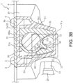
- FIG. 3B is a partially enlarged cross-sectional view of the percussion instrument 1 showing a state in which the horizontal rod 100a is tightened by the first tightening portion 31.
- FIG. 3A and FIG. 3B shows a cross section cut along a plane perpendicular to the insertion direction of the horizontal rod 100a, which shows a cross section including a protrusion 33 located on the insertion hole 11a side among the pair of protrusions 33 (see FIG. 2 ) of the first tightening member 30.
- a slit 31b is formed in the lower end portion of the first tightening portion 31, partially dividing the first tightening portion 31 in a circumferential direction (the direction around the inner circumferential surface 31a).
- the slit 31b is a crack extending across two ends in the axial direction of the inner circumferential surface 31a of the first tightening portion 31, and one end of the slit 31b in the longitudinal direction (the end on the insertion hole 11a side) is connected to a slit 32a (see FIG. 2 ).
- the slit 32a is formed by cutting out the base part of the annular portion 32 (the part connected to the first tightening portion 31) over approximately half the circumference.
- the formation of these slits 31b and 32a enables the first tightening portion 31 formed in a substantially C-shape to be elastically deformed (deformed to narrow the width of the slit 31b).
- a side surface 31c of the first tightening portion 31 facing the tightening bolt 20 side (left side in FIG. 3A and FIG. 3B ) is formed in an arc shape corresponding to the inner circumferential surface 31a of the first tightening portion 31 (centered on the central axis of the inner circumferential surface 31a), and the protrusion 33 is integrally formed at the lower end portion (near the slit 31b) of the side surface 31c of the first tightening portion 31.
- a recessed portion 34 (see FIG. 3A and FIG. 3B ) is formed at the connection between the base of the protrusion 33 and the side surface 31c of the first tightening portion 31, and the recessed portion 34 is formed in a groove shape extending across two ends of the protrusion 33 in the insertion direction of the horizontal rod 100a (the direction perpendicular to the paper surface of FIG. 3A and FIG. 3B ).
- the bottom surface of the recessed portion 34 (the surface facing the tightening bolt 20) is curved to be projecting toward the opposite side to the tightening bolt 20 (the right side in FIG. 3A and FIG. 3B ), and a projecting portion 41 of the second tightening member 40 is fitted into this recessed portion 34.
- the projecting portion 41 has a curved shape along the recessed portion 34 (projecting toward the recessed portion 34 side).
- Each of the tightening members 30 and 40 is housed in the cavity S of the bracket 10 with the projecting portion 41 fitted into the recessed portion 34. In this housed state, the displacement of the first tightening member 30 in each direction is regulated by the bottom frame 2 and the bracket 10.
- the displacement of the first tightening member 30 in the insertion direction of the horizontal rod 100a is regulated by the outer circumferential wall 11 of the bracket 10 (see FIG. 2 ) and the above-mentioned regulating wall 2b of the bottom frame 2 (see FIG. 4B ).
- a leg portion 34 is integrally formed on a side surface 31d of the first tightening portion 31 facing the opposite side to the tightening bolt 20 (the right side in FIG. 3A and FIG. 3B ) and is continuing to the side surface 31d, and the leg portion 34 protrudes downward from the slit 31b and is supported by the bottom wall 12 of the bracket 10.
- the bottom frame 2 also includes a protrusion 2a sandwiched between the reinforcement frame 8 (protrusion 8a) and the bracket 10, and the first tightening member 30 is covered from above by this protrusion 2a.
- the up and down displacement of the first tightening member 30 is regulated by the protrusion 2a of the bottom frame 2 and the bottom wall 12 of the bracket 10.
- a female screw hole 13a (see FIG. 2 ) is formed in the side wall 13 of the pair of side walls 13 of the bracket 10 on the opposite side from the leg portion 34, and a shaft portion 21 of the tightening bolt 20 is tightened to this female screw hole 13a. Since the second tightening member 40 is provided on the tip side of the shaft portion 21 of this tightening bolt 20, the tightening force when the tightening bolt 20 is tightened acts on the second tightening member 40.
- the second tightening member 40 undergoes sliding displacement along the tightening direction of the tightening bolt 20, and as a result of this sliding displacement, the protrusion 33 (recessed portion 34) of the first tightening member 30 is pushed into the projecting portion 41 of the second tightening member 40 (see FIG. 3B ).
- the protrusion 33 of the first tightening member 30 is pushed in, the first tightening portion 31 is elastically deformed so as to reduce the diameter of the inner circumferential surface 31a thereof (to narrow the width of the slit 31b), and the horizontal rod 100a is tightened. As a result, the horizontal rod 100a is fixed to the bracket 10.
- FIG. 4A is a partially enlarged cross-sectional view of the percussion instrument 1 showing a state in which the horizontal rod 100b is tightened by the second tightening portion 42 of the second tightening member 40
- FIG. 4B is a partially enlarged cross-sectional view of the percussion instrument 1 showing a state in which the vertical rod 100c is tightened by the second tightening portion 42 of the second tightening member 40. It is noted that FIG. 4B corresponds to a cross section taken along line IVb-IVb in FIG. 4A .
- FIG. 4A corresponds to a cross section taken along line IVb-IVb in FIG. 4A .
- an insertion hole 14a is formed in the inner circumferential wall 14 of the bracket 10, and this insertion hole 14a faces the insertion hole 11b (see FIG. 2 ) in the insertion direction of the horizontal rod 100b.
- the protrusion 33 and the leg portion 34 of the first tightening member 30 are formed on two sides of the insertion hole 14a (positions avoiding the insertion hole 14a) when viewed in the insertion direction of the horizontal rod 100b (see FIG. 4A ).
- the horizontal rod 100b inserted from the insertion hole 11b passes between the protrusion 33 and the leg portion 34 of the first tightening member 30 and is inserted into the insertion hole 14a.
- a pair of protrusions 33 are formed (see FIG. 2 ) in line in the insertion direction of the horizontal rod 100a (the direction perpendicular to the paper surface of FIG. 4A ), and the second tightening portion 42 of the second tightening member 40 is inserted between the pair of protrusions 33.
- the second tightening portion 42 is a protrusion formed integrally with the projecting portion 41 of the second tightening member 40, and the second tightening portion 42 is formed in a substantially central part of the projecting portion 41 in the insertion direction of the horizontal rod 100a (see FIG. 2 ).
- a groove 42a for tightening the horizontal rod 100b is formed at the tip of the second tightening portion 42 (the right end portion in FIG. 4A ).
- the groove 42a is formed in a V-shape recessed in a direction away from the central axis of the insertion hole 14a when viewed in the insertion direction of the horizontal rod 100b.
- the groove 42a is formed at a position that protrudes further toward the center side of the insertion hole 14a than the protrusion 33 when viewed in the insertion direction of the horizontal rod 100b (see FIG. 4A ).
- the groove 42a of the second tightening portion 42 pushes the horizontal rod 100b against the inner circumferential surface of the insertion hole 14a.
- the horizontal rod 100b is also pushed against the inner circumferential surface of the insertion hole 11b (see FIG. 2 ). That is, the horizontal rod 100b is fixed to the bracket 10 by being sandwiched between the groove 42a of the second tightening portion 42 and the insertion holes 11b and 14a.
- An insertion hole 12a for inserting the vertical rod 100c is formed in the bottom wall 12 of the bracket 10 (see FIG. 2 ), and a pair of through holes 31e and 31f are formed at positions overlapping the insertion hole 12a in the up and down direction in the first tightening portion 31 of the first tightening member 30.
- the through hole 31e is a hole that connects the lower surface of the first tightening portion 31 to the inner circumferential surface 31a
- the through hole 31f is a hole that connects the upper surface of the first tightening portion 31 to the inner circumferential surface 31a.
- a through hole 2c is also formed in the protrusion 2a of the bottom frame 2 that covers the first tightening portion 31 from above (see FIG. 6B ).
- the vertical rod 100c (see FIG. 4B ) inserted from below the insertion hole 12a is inserted into the insertion hole 8b of the reinforcement frame 8 through the through holes 31e and 31f (see FIG. 2 ) of the first tightening member 30.
- the inserted state of the vertical rod 100c is also fixed by the second tightening member 40.
- a groove 42b for tightening the vertical rod 100c is formed at the tip of the second tightening portion 42 of the second tightening member 40.
- the groove 42b is formed in a V-shape recessed in a direction away from the central axis of the insertion hole 12a when viewed in the insertion direction of the vertical rod 100c (see FIG. 4B ). It is noted that, the depth of the groove 42b from the tip of second tightening portion 42 is formed deeper than the groove 42a (see FIG. 2 ), and a pair of grooves 42a are formed on two sides of the groove 42b (separated from each other in the insertion direction of the horizontal rod 100b).
- the groove 42b of the second tightening portion 42 is formed at a position that protrudes further toward the center side of the insertion hole 12a than the through hole 31e of the first tightening portion 31 when viewed in the insertion direction of the vertical rod 100c (see FIG. 4B ).
- the groove 42b of the second tightening portion 42 pushes the vertical rod 100c against the inner circumferential surface of the insertion hole 12a.
- the vertical rod 100c is also pushed against the inner circumferential surface of the insertion hole 8b (see FIG. 2 ). That is, the vertical rod 100c is fixed to the bracket 10 by being sandwiched between the groove 42b of the second tightening portion 42 and the insertion holes 8b and 12a.
- the horizontal rod 100a inserted into the insertion hole 11a (first tightening portion 31) is capable to be tightened by the first tightening portion 31 of the first tightening member 30 (see FIG. 3B ), and the horizontal rod 100b inserted into the insertion holes 11b and 14a is capable to be tightened by the second tightening portion 42 (groove 42a) of the second tightening member 40 (see FIG. 4A ).
- the percussion instrument 1 may be supported by two horizontal rods 100a and 100b that extend in the same direction (horizontal direction) and have different diameters, thereby improving versatility.
- the vertical rod 100c extending in a direction different from the horizontal rods 100a and 100b may also be tightened by the groove 42b of the second tightening portion 42.
- the versatility of the percussion instrument 1 may be further improved.
- the elastic restoring force of the first tightening portion 31 may be utilized to return each of the tightening members 30 and 40 to their initial positions (the state before the tightening bolt 20 is tightened).
- the tightening portions 31 and 42 may be suppressed from interfering with (getting caught on) the insertion of each of the rods 100a to 100c, thereby improving the workability when the percussion instrument 1 is supported by the rods 100a to 100c.
- a configuration in which a second tightening portion 242 is integrally formed with a tightening member 230 may also be adopted, as in the second embodiment described later (see FIG. 6A and FIG. 6B ).
- the first tightening portion 31 is deformed such that the second tightening portion 242 rotates with the upper end portion of the first tightening portion 31 being the center.
- the second tightening portion 242 is not able to be displaced along the tightening direction of the tightening bolt 20.
- first tightening member 30 having the first tightening portion 31 and the second tightening member 40 having the second tightening portion 42 are separate parts, and in this configuration, the first tightening portion 31 is elastically deformed by utilizing the sliding displacement of the second tightening member 40 caused by the tightening force of the tightening bolt 20.
- the second tightening portion 42 may be suppressed from accompanying the elastic deformation of the first tightening portion 31.
- the second tightening portion 42 (second tightening member 40) becomes more easily displaced along the tightening direction of the tightening bolt 20, so that the tightening force of the tightening bolt 20 is more easily transmitted to the horizontal rod 100b and the vertical rod 100c.
- each of the rods 100b and 100c may be firmly fixed to the bracket 10.
- each of the rods 100b and 100c may be firmly fixed to the bracket 10.
- the protrusion 33 protrudes from the outer circumferential surface (near the slit 31b) of the first tightening portion 31, and since the protrusion 33 formed on the displacement locus of the second tightening member 40 is pushed in by the second tightening member 40, the first tightening portion 31 is more easily elastically deformed. This is because, when the first tightening portion 31 is elastically deformed starting from the upper end portion thereof, the first tightening portion 31 may be pushed in at a position away from the starting point of the elastic deformation.
- a pair of protrusions 33 are formed in line in the insertion direction of the horizontal rod 100b (horizontal rod 100a), and the second tightening portion 42 is configured to tighten the horizontal rod 100b with the second tightening portion 42 protruding from between the pair of protrusions 33.
- the tightening position of the horizontal rod 100a by the first tightening portion 31 and the tightening position by the second tightening portion 42 may be brought closer to each other.
- the distance between the insertion holes 11a and 11b may be made small, and the bracket 10 may be made compact.
- the leg portion 34 is formed extending downward from the first tightening portion 31, and the second tightening portion 42 (grooves 42a and 42b) and the leg portion 34 face each other in the tightening direction of the tightening bolt 20.
- each of the rods 100b and 100c may be tightened by the second tightening portion 42 and the leg portion 34.
- each of the rods 100b and 100c since each of the rods 100b and 100c is tightened at one point (approximately one point) in the longitudinal direction, each of the rods 100b and 100c may not be firmly fixed to the bracket 10.
- the horizontal rod 100b is fixed to the bracket 10 by being sandwiched at multiple points between the groove 42a of the second tightening portion 42 and the edges of the two insertion holes 11b and 14a.
- the vertical rod 100c is fixed to the bracket 10 by being sandwiched at multiple points between the groove 42b of the second tightening portion 42 and the edges of the two insertion holes 8b and 12a. In this way, by tightening each of the rods 100b and 100c at multiple points in the longitudinal direction, each of the rods 100b and 100c may be firmly fixed to the bracket 10.
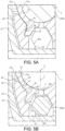
- FIG. 5A is a partially enlarged cross-sectional view of the percussion instrument 1 in part Va in FIG. 3B
- FIG. 5B is a partially enlarged cross-sectional view of the percussion instrument 1 in part Vb in FIG. 4A .
- the second tightening member 40 is formed with a projecting surface 43 forming the tip surface of the projecting portion 41, a recessed surface 44 continuing to the upper edge of the projecting surface 43, and a flank surface 45 continuing to the upper edge of the recessed surface 44.
- the projecting surface 43 is formed in a projecting arc shape toward the recessed portion 34 side of the first tightening portion 31, and the curvature of the projecting surface 43 is the same as that of the recessed portion 34.
- the recessed surface 44 is formed in a projecting arc shape in a direction away from the side surface 31c of the first tightening portion 31, and the curvature of the recessed surface 44 is the same as that of the side surface 31c of the first tightening portion 31.
- flank surface 45 continuing to the upper edge of the recessed surface 44 is formed in an upwardly projecting arc shape, and by forming such a flank surface 45 on the upper end part of the second tightening member 40, the contact area between the second tightening member 40 and the side surface 31c of the first tightening portion 31 may be reduced.
- the second tightening member 40 is in contact with the side surface 31c of the first tightening portion 31 below the center C of the line segment connecting the lower end of the virtual circle V (the center of the slit 31b in the circumferential direction of the inner circumferential surface 31a) and the central axis O.
- the side surface 31c of the first tightening portion 31 is suppressed from interfering with the upper edge of the second tightening member 40 when the second tightening member 40 slides while pushing up the first tightening portion 31.
- the second tightening portion 42 (groove 42a) is suppressed from being tilted, so that the horizontal rod 100b may be appropriately tightened.
- the horizontal rod 100b may be firmly fixed to the bracket 10.
- flank surface 45 is formed to be continuous with the upper edge of the recessed surface 44, but this is not necessarily limited thereto.
- the recessed surface 44 may be omitted, and the flank surface 45 may be formed to be continuous with the upper edge of the projecting surface 43.
- the side surface 31c of the first tightening portion 31 may also be suppressed from interfering with the upper edge of the second tightening member 40 when the second tightening member 40 slides while pushing up the first tightening portion 31.
- FIG. 6A is a perspective view of the tightening member 230 of the second embodiment
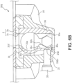
- FIG. 6B is a partially enlarged cross-sectional view of the percussion instrument 201 of the second embodiment.
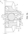
- FIG. 7A is a partially enlarged cross-sectional view of the percussion instrument 201 showing a state in which the horizontal rod 100a is tightened by the first tightening portion
- FIG. 7B is a partially enlarged cross-sectional view of the percussion instrument 201 showing a state in which the horizontal rod 100b is tightened by the groove 42a of the second tightening portion 242.
- FIG. 6B , FIG. 7A , and FIG. 7B show cross sections cut along a plane that includes the shaft portion 21 of the tightening bolt 20 and is perpendicular to the insertion direction of the horizontal rods 100a and 100b.
- the tightening member 230 of the percussion instrument 201 of the second embodiment has the same configuration as the first tightening member 30 of the first embodiment, except for the point that the protrusions 33 (see FIG. 2 ) are omitted and the point that the first tightening portion 31 and the second tightening portion 242 are integrally formed.
- the second tightening portion 242 extends downward so as to be continuous with the side surface 31c of the first tightening portion 31, and a recessed portion 242c into which the shaft portion 21 is fitted is formed on the side surface of the second tightening portion 242 facing the tightening bolt 20.
- the first tightening portion 31 is elastically deformed so as to reduce the diameter of the inner circumferential surface 31a.
- the second tightening portion 242 and the leg portion 34 face each other across the insertion hole 14a, and the groove 42a is formed on the side surface of the second tightening portion 242 facing the leg portion 34.
- the horizontal rod 100b is tightened by the groove 42a of the second tightening portion 242.
- the through hole 31e for inserting the vertical rod 100c extends upward and downward so as to be continuous with the second tightening portion 242.
- the vertical rod 100c inserted into the insertion hole 8b through the insertion hole 12a and the through holes 31e, 31f, and 2c is fixed to the bracket 10 by being sandwiched at multiple points between the second tightening portion 242 (the inner circumferential surface of the through hole 31e) and the edges of the two insertion holes 8b and 12a.
- the horizontal rods 100a and 100b and the vertical rod 100c may be tightened by the first tightening portion 31 and the second tightening portion 242 of the tightening member 230.
- the percussion instrument 201 may be supported by the two horizontal rods 100a and 100b that extend in the same direction (horizontal direction) and have different diameters, while the percussion instrument 201 may also be supported by the vertical rod 100c that extends in a direction different from that of the horizontal rods 100a and 100b.
- the versatility of the percussion instrument 201 may be improved.
- the tightening member 230 is integrally formed with the first tightening portion 31 for tightening the horizontal rod 100a and the second tightening portion 242 for tightening the horizontal rod 100b.
- the number of parts may be reduce compared to the above-mentioned first embodiment in which the first tightening member 30 (first tightening portion 31) and the second tightening member 40 (second tightening portion 42) are separate, and the work of assembling the bracket 10 and the tightening member 230 to the percussion instrument 201 may be facilitated.
- the horizontal rod 100b of this embodiment is formed into a columnar shape having a smaller diameter than the horizontal rod 100a, it is of course possible to tighten the polygonal horizontal rod 100b similar to the first embodiment using the second tightening portion 242 (groove 42a) (the same applies to the third to sixth embodiments described later).
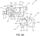
- FIG. 8A is a perspective view of the back surface of the bracket 310 of the third embodiment
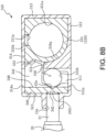
- FIG. 8B is a cross-sectional view of the bracket 310
- FIG. 9A is a cross-sectional view of the bracket 310 showing a state in which the horizontal rod 100a is tightened by the first tightening portion 331
- FIG. 9B is a cross-sectional view of the bracket 310 showing a state in which the horizontal rod 100b is tightened by the second tightening portion 342.
- the bracket 310 of the third embodiment is formed in a box shape having an opening on the side of the housing (not shown) of the percussion instrument. More specifically, an outer circumferential wall 311 of the bracket 310 is provided with circular insertion holes 311a and 311b for inserting the horizontal rods 100a and 100b (see FIG. 9A and FIG. 9B ). These insertion holes 311a and 311b are formed in line in the tightening direction of the tightening bolt 20 (the left and right direction in FIG. 8B ).
- a lower wall 312 extends from the lower end of the outer circumferential wall 311 toward the housing side of the percussion instrument (the front side of the direction perpendicular to the paper surface of FIG. 8A and FIG. 8B ), and a pair of side walls 313 extend upward from two ends of the lower wall 312 in the tightening direction of the tightening bolt 20 (the left and right direction in FIG. 8B ).
- the upper ends of the pair of side walls 313 are connected to each other by an upper wall 314, and the lower wall 312 and the upper wall 314 are provided with insertion holes 312a and 314a for inserting the vertical rod 100c.
- Each of the walls 311 to 314 of the bracket 310 are integrally formed using metal, and a substantially rectangular parallelepiped cavity S is formed in the bracket 310 and is surrounded by each of the walls 311 to 314.
- a first tightening member 330 and a second tightening member 340 are housed through an opening part formed on the housing side of the percussion instrument.
- a pair of fastening portions 315 that protrude on two sides in the tightening direction of the tightening bolt 20 are integrally formed on the pair of side walls 313, and by screwing this fastening portions 315 to the housing of the percussion instrument, the bracket 310 and each of the tightening members 330 and 340 are assembled to the housing of the percussion instrument.
- the first tightening member 330 is a resin part for tightening the horizontal rod 100a
- the second tightening member 340 is a metal part for tightening the horizontal rod 100b and the vertical rod 100c.
- the first tightening member 330 includes a first tightening portion 331 having an inner circumferential surface 331a with a circular cross section corresponding to the insertion hole 311a.
- first tightening portion 331 having an inner circumferential surface 331a with a circular cross section corresponding to the insertion hole 311a.
- a slit 331b is formed in the upper end portion of the first tightening portion 331, partially dividing the first tightening portion 331 in a circumferential direction (the direction around the inner circumferential surface 331a).
- the slit 331b is a crack extending across two ends in the axial direction of the inner circumferential surface 331a of the first tightening portion 331, and the formation of this slit 331b enables the first tightening portion 331 formed in a substantially C-shape to be elastically deformed (deformed to narrow the width of the slit 331b).
- a side surface 331c of the first tightening portion 331 facing the tightening bolt 20 side is formed in an arc shape corresponding to the inner circumferential surface 331a of the first tightening portion 331 (centered on the central axis of the inner circumferential surface 331a).
- a partition wall 316 supporting the side surface 331c of the first tightening portion 331 rises upward from the lower wall 312 of the bracket 310.
- a side surface 316a (see FIG. 8B ) of the partition wall 316 facing the first tightening portion 331 side is a curved surface that runs along the side surface 331c of the first tightening portion 331.
- a recessed portion 333 is formed on the upper end side of the side surface 331c of the first tightening portion 331.
- the recessed portion 333 is formed in a groove shape extending across two ends of the side surface 331c of the first tightening portion 331 in the insertion direction of the horizontal rod 100a (the direction perpendicular to the paper surface of FIG. 9A ).
- the recessed portion 333 has a curved shape that protrudes toward the opposite side to the tightening bolt 20 (the right side in FIG. 9A ), and a projecting portion 341 of the second tightening member 340 that extends between the upper wall 314 and the partition wall 316 is fitted into this recessed portion 333.
- the tip surface of the projecting portion 341 has a curved shape that runs along the recessed portion 333 (protrudes toward the recessed portion 333 side), and the second tightening portion 342 extending downward is integrally formed at the base end of the projecting portion 341 (the end portion on the tightening bolt 20 side).
- a female screw hole 13a is formed in the side wall 313 of the bracket 310 facing the second tightening portion 342, and a recessed portion 242c for inserting the shaft portion 21 of the tightening bolt 20 is formed on the side surface of the second tightening portion 342 facing the tightening bolt 20.
- the recessed portion 333 is pushed in by the projecting portion 341, and the first tightening portion 331 elastically deforms to reduce the diameter of the inner circumferential surface 331a (to narrow the width of the slit 331b) (see FIG. 9A ).
- the horizontal rod 100a is tightened by the elastic deformation of this first tightening portion 331, and the horizontal rod 100a is fixed to the bracket 310.
- the second tightening portion 342 and the partition wall 316 face each other across the insertion hole 311b, and a groove 42a is formed on the side surface of the second tightening portion 342 facing the partition wall 316.
- a groove 316b having a projecting arc shape is formed on the side surface of the partition wall 316 facing the second tightening portion 342, opposite to the groove 42a.
- the groove 316b extends in the insertion direction of the horizontal rod 100b (the direction perpendicular to the paper surface of FIG. 9B ) and is connected to the inner circumferential surface of the insertion hole 311b.
- the horizontal rod 100b is tightened by the insertion hole 311b, the groove 42a of the second tightening portion 342, and the groove 316b of the partition wall 316.
- the second tightening member 340 and the partition wall 316 are formed with grooves 346 and 316c for passing the vertical rod 100c therethrough.
- the groove 346 extends upwardly and downwardly and is continuous with the insertion hole 312a of the lower wall 312 and the insertion hole 314a of the upper wall 314.
- the groove 316c of the partition wall 316 extends upwardly and downwardly and is continuous with the insertion hole 12a of the lower wall 312.
- the vertical rod 100c inserted into the insertion hole 314a through the insertion hole 312a and the grooves 346 and 316c is tightened by the insertion holes 312a and 314a and the grooves 346 and 316c.
- the horizontal rods 100a and 100b and the vertical rod 100c may be tightened by the first tightening portion 331 and the second tightening portion 342 of each of the tightening members 330and 340.
- the percussion instrument may be supported by the two horizontal rods 100a and 100b that extend in the same direction (horizontal direction) and have different diameters, while the percussion instrument may also be supported by the vertical rod 100c that extends in a direction different from that of the horizontal rods 100a and 100b.
- the versatility of the percussion instrument may be improved.
- each of the rods 100b and 100c may be firmly fixed to the bracket 310.
- the elastic restoring force of the first tightening portion 331 may be utilized to return each of the tightening members 330 and 340 to their initial positions (the state before the tightening bolt 20 is tightened).
- the first tightening portion 331 and the second tightening portion 342 may be suppressed from interfering with (getting caught on) the insertion of the each of the rods 100a to 100c.
- first tightening member 330 having the first tightening portion 331 and the second tightening member 340 having the second tightening portion 342 are separate parts, and in this configuration, the first tightening portion 331 is elastically deformed by the sliding displacement of the second tightening member 340.
- the second tightening portion 342 may be suppressed from accompanying the elastic deformation of the first tightening portion 331.
- the second tightening portion 342 (second tightening member 340) becomes more easily displaced along the tightening direction of the tightening bolt 20, so that the tightening force of the tightening bolt 20 is more easily transmitted to the horizontal rod 100b and the vertical rod 100c.
- FIG. 10A is a cross-sectional view of the bracket 410 of the fourth embodiment
- FIG. 10B is a cross-sectional view of the bracket 410 showing a state in which the horizontal rods 100a and 100b are tightened by the first tightening portion 431 and the second tightening portion 442. It is noted that FIG. 10A and FIG. 10B shows a cross section of the bracket 410 cut along a plane corresponding to that in FIG. 9 .
- FIG. 10B shows a state in which each of the horizontal rods 100a and 100b are tightened by the first tightening portion 431 and the second tightening portion 442, respectively, when the percussion instrument is actually supported on a drum set, either one of the rods is tightened by the first tightening portion 431 or the second tightening portion 442.
- the bracket 410 of the fourth embodiment has the same configuration as the bracket 310 of the third embodiment, except for the point that the partition wall 316 (see FIG. 9 ) is omitted.
- the bracket 410 is formed with insertion holes 311a, 311b, 312a, and 314a for inserting each of the rods 100a to 100c therein.
- the tightening member 430 is a resin part for tightening each of the rods 100a to 100c.
- the tightening member 430 includes a cylindrical first tightening portion 431 having an inner circumferential surface 431a with a circular cross section corresponding to the horizontal rod 100a (insertion hole 311a), and a slit 431b is formed in the lower end portion of the first tightening portion 431, partially dividing the first tightening portion 431 in a circumferential direction (the direction around the inner circumferential surface 431a).
- the slit 431b is a crack extending across two ends in the axial direction of the inner circumferential surface 431a of the first tightening portion 431, and the formation of this slit 431b enables the first tightening portion 431 formed in a substantially C-shape to be elastically deformed (deformed to narrow the width of the slit 431b).
- the first tightening portion 431 is integrally formed with a second tightening portion 442 for tightening the horizontal rod 100b.
- the first tightening portion 431 and the second tightening portion 442 are both formed in a substantially rectangular parallelepiped shape, and the tightening member 430 is housed inside the bracket 410.
- the shaft portion 21 of the tightening bolt 20 and the second tightening portion 442 face each other.
- a recessed portion 242c is formed on the side surface of the second tightening portion 442 facing the tightening bolt 20 side, and the tightening force of the tightening bolt 20 acts on the second tightening portion 442.
- the entire tightening member 440 is elastically deformed so as to be compressed in the tightening direction of the tightening bolt 20, thereby elastically deforming the cylindrical first tightening portion 431 so as to reduce the diameter of the inner circumferential surface 431a (to narrow the width of the slit 431b).
- the diameter of the inner circumferential surface 431a of the first tightening portion 431 is formed to be larger than the diameter of the insertion hole 311a, and the horizontal rod 100a is sandwiched between the insertion hole 311a and the inner circumferential surface 431a of the first tightening portion 431 by elastic deformation of the first tightening portion 431, it is of course possible to form the inner circumferential surface 431a of the first tightening part 431 with a diameter smaller than the diameter of the insertion hole 311a.
- the second tightening portion 442 is formed with a through hole 442d, which is continuous with the insertion hole 311b (extending in the insertion direction of the horizontal rod 100b).
- the second tightening portion 442 is elastically deformed so as to slightly narrow the through hole 442d, and in accordance with the elastic deformation of the first tightening portion 431, the second tightening portion 442 performs sliding displacement.
- the horizontal rod 100b is tightened by being sandwiched between the insertion hole 311b and the through hole 442d of the second tightening portion 442.
- a through hole 442e is formed at a position overlapping the insertion holes 312a and 314a in the up and down direction.
- the vertical rod 100c inserted into the insertion hole 314a through the insertion hole 312a and the through hole 442e is fixed to the bracket 410 by being tightened to the insertion holes 312a and 314a and the through hole 442e.
- the horizontal rods 100a and 100b and the vertical rod 100c may be tightened by the first tightening portion 431 and the second tightening portion 442.
- the percussion instrument may be supported by the two horizontal rods 100a and 100b that extend in the same direction (horizontal direction) and have different diameters, while the percussion instrument may also be supported by the vertical rod 100c that extends in a direction different from that of the horizontal rods 100a and 100b.
- the versatility of the percussion instrument may be improved.
- the through hole 442d and the through hole 442e of the second tightening portion 442 are formed at positions overlapping the shaft portion 21 of the tightening bolt 20 in the tightening direction of the tightening bolt 20, the tightening force of the tightening bolt 20 is easily transmitted to the horizontal rod 100b and the vertical rod 100c.
- first tightening portion 431 and the second tightening portion 442 for tightening the horizontal rods 100a and 100b are integrally formed, the number of parts may be reduced, and the work of assembling the bracket 410 and the tightening member 430 to the percussion instrument is facilitated.
- the elastic restoring force of the first tightening portion 431 may be utilized to return each of the tightening members 430 and 440 to their initial positions (the state before the tightening bolt 20 is tightened).
- the first tightening portion 431 and the second tightening portion 442 may be suppressed from interfering with (getting caught on) the insertion of each of the rods 100a to 100c.
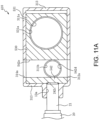
- FIG. 11A is a cross-sectional view of the bracket 410 of the fifth embodiment
- FIG. 11B is a cross-sectional view of the bracket 410 showing a state in which the horizontal rods 100a and 100b are tightened by the first tightening portion 531 and the second tightening portion 542. It is noted that FIG. 11A and FIG. 11B shows a cross section of the bracket 410 cut along a plane corresponding to that in FIG. 10A and FIG.10B .
- FIG. 11B shows a state in which the horizontal rods 100a and 100b are tightened by the first tightening portion 531 and the second tightening portion 542, respectively, when the percussion instrument is actually supported on a drum set, either one of the rods is tightened by the first tightening portion 531 or the second tightening portion 542.
- the tightening member 530 of the fifth embodiment is a metal or resin part formed in a rectangular parallelepiped shape that is long in the tightening direction of the tightening bolt 20.
- the bracket 410 with the tightening member 530 housed therein is screwed to the housing of the percussion instrument, whereby the bracket 410 and the tightening member 530 are assembled to the housing of the percussion instrument.
- a gap is formed between the pair of side walls 313 of the bracket 410 and the tightening member 530, allowing the sliding displacement of the tightening member 530 in the tightening direction of the tightening bolt 20.
- the tightening member 530 is integrally formed with the first tightening portion 531 having a through hole 531a with a circular cross section connected to the insertion hole 311a and the second tightening portion 542 having a through hole 542d with a circular cross section connected to the insertion hole 311b.
- a recessed portion 242c is formed on the side surface of the second tightening portion 542 facing the tightening bolt 20 side, and the tightening force of the tightening bolt 20 acts on the second tightening portion 542.
- the tightening member 530 performs sliding displacement along the tightening direction of the tightening bolt 20.
- the horizontal rod 100a is tightened by being sandwiched between the insertion hole 311a and the through hole 531a of the first tightening portion 531.
- the horizontal rod 100b is tightened by being sandwiched between the insertion hole 311b and the through hole 542d of the second tightening portion 542.
- the second tightening portion 542 is formed with a through hole 542e that extends upwardly and downwardly and connects to the insertion holes 312a and 314a.
- the vertical rod 100c inserted into the insertion hole 314a through the insertion hole 312a and the through hole 542e is fixed to the bracket 410 by being tightened to the insertion holes 312a and 314a and the through hole 542e.
- the horizontal rods 100a and 100b and the vertical rod 100c may be tightened by the first tightening portion 531 and the second tightening portion 542.
- the percussion instrument may be supported by the two horizontal rods 100a and 100b that extend in the same direction (horizontal direction) and have different diameters, while the percussion instrument may also be supported by the vertical rod 100c that extends in a direction different from that of the horizontal rods 100a and 100b.
- the versatility of the percussion instrument may be improved.
- each of the rods 100b and 100c may be firmly fixed to the bracket 410.
- first tightening portion 531 and the second tightening portion 542 for tightening the horizontal rods 100a and 100b are integrally formed, the number of parts may be reduced, and the work of assembling the bracket 410 and the tightening member 530 to the percussion instrument is facilitated.
- each of the rods 100a to 100c are tightened by the sliding displacement of the tightening member 530, compared to the case where the tightening member is elastically deformed, fatigue of the tightening member 530 may be suppressed.
- the tightening member 530 is simply slidably held inside the bracket 410, but the disclosure is not limited thereto.
- an elastic body such as a spring for returning the tightening member 530 to the initial position thereof may be provided between the tightening member 530 and the side walls 313 of the bracket 410.
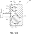
- FIG. 12A is a cross-sectional view of the bracket 610 of the sixth embodiment
- FIG. 12B is a cross-sectional view of the bracket 610 showing a state in which the horizontal rods 100a and 100b are tightened by the first tightening portion 631 and the second tightening portion 642. It is noted that FIG. 12A and FIG. 12B shows a cross section of the bracket 610 cut along a plane corresponding to that in FIG. 11A and FIG. 11B .
- FIG. 12B shows a state in which the horizontal rods 100a and 100b are tightened by the first tightening portion 631 and the second tightening portion 642, respectively, when the percussion instrument is actually supported on a drum set, either one of the rods is tightened by the first tightening portion 631 or the second tightening portion 642.
- the bracket 610 of the sixth embodiment has insertion holes 311a and 311b formed in line in the up and down direction in an outer circumferential wall 611, and the bracket 610 has the same configuration as the bracket 410 of the fifth embodiment except for the point that the outer shape of the bracket 610 is a rectangular parallelepiped that is long in the up and down direction.
- the tightening member 630 is a metal or resin part formed into a rectangular parallelepiped shape that is long in the up and down direction.
- the bracket 610 with the tightening member 630 housed therein is screwed to the housing of the percussion instrument, whereby the bracket 610 and the tightening member 630 are assembled to the housing of the percussion instrument.
- a gap is formed between the pair of side walls 313 of the bracket 610 and the tightening member 630, and the bracket 610 slidably holds the tightening member 630 in the tightening direction of the tightening bolt 20.
- the tightening member 630 is integrally formed with the first tightening portion 631 having a through hole 631a with a circular cross section connected to the insertion hole 311a and the second tightening portion 642 having a through hole 642d with a circular cross section connected to the insertion hole 311b.
- a recessed portion 242c is formed on the side surface of the tightening member 630 facing the tightening bolt 20 side, and the tightening force of the tightening bolt 20 acts on the tightening member 630. As a result, the tightening member 630 performs sliding displacement along the tightening direction of the tightening bolt 20.
- the horizontal rod 100a is tightened by being sandwiched between the insertion hole 311a and the through hole 631a of the first tightening portion 631.
- the horizontal rod 100b is tightened by being sandwiched between the insertion hole 311b and the through hole 642d of the second tightening portion 642.
- the tightening member 630 has a through hole 635 that intersects with each of the through holes 631a and 642d of the first tightening portion 631 and the second tightening portion 642, and this through hole 635 extending upwardly and downwardly is connected to the insertion holes 312a and 314a.
- the vertical rod 100c inserted into the insertion hole 314a through the insertion hole 312a and the through hole 635 is fixed to the bracket 610 by being tightened to the insertion holes 312a and 314a and the through hole 635.
- the horizontal rods 100a and 100b and the vertical rod 100c may be tightened by the first tightening portion 631 and the second tightening portion 642.
- the percussion instrument may be supported by the two horizontal rods 100a and 100b that extend in the same direction (horizontal direction) and have different diameters, while the percussion instrument may also be supported by the vertical rod 100c that extends in a direction different from that of the horizontal rods 100a and 100b.
- the versatility of the percussion instrument may be improved.
- first tightening portion 631 and the second tightening portion 642 for tightening the horizontal rods 100a and 100b are integrally formed, the number of parts may be reduced, and the work of assembling the bracket 610 and the tightening member 630 to the percussion instrument is facilitated.
- each of the rods 100a to 100c are tightened by the sliding displacement of the tightening member 630, compared to the case where the tightening member is elastically deformed, fatigue of the tightening member 630 may be suppressed.
- the percussion instruments 1 and 201 are electronic percussion instruments, but the disclosure is not necessarily limited thereto.
- the above-mentioned configuration of each of the embodiments may be applied to the case where an acoustic percussion instrument (drum) is supported on each of the rods 100a to 100c.
- the first tightening portions 31, 331, 431, 531, and 631 and the second tightening portions 42, 242, 342, 442, 542, and 642 (hereinafter, simply referred to as the "tightening portion.”), but the disclosure is not necessarily limited thereto. It may also be configured such that two types of rods extending in a vertical direction (or in a direction inclined relative to the vertical direction) and having different diameters are tightened by the tightening portion. In this configuration, the orientation of the tightening portion may be changed according to the direction in which the rod extends.
- three or more types of rods extending in the same direction may be tightened by the tightening portion.
- a configuration is illustrated in which an insertion hole for inserting a third type of rod is added below the insertion hole 11b of the bracket of the first and second embodiments, the second tightening portions 42 and 242 are extended downward, and the third type of rod is tightened by the extended part.
- a configuration is illustrated in which, in addition to the insertion holes 311a and 311b of the fifth and sixth embodiments, an insertion hole for inserting a third type of rod is added, and a through hole connected to the insertion hole is formed in the tightening members 530 and 630.
- the tightening portion may be formed at a position that does not overlap the shaft portion 21 of the tightening bolt 20.
- the vicinity of the slit 31b is the area below the center C (slit 31b side) of the line segment connecting the lower end of the virtual circle V (the center of the slit 31b in the circumferential direction of the inner circumferential surface 31a) and the central axis O shown in FIG. 5B .
- a pair of protrusions 33 are formed in line in the insertion direction of the horizontal rod 100b (horizontal rod 100a), but this is not necessarily limited thereto.
- the protrusions 33 may be formed across two ends of the first tightening portion 31 in the insertion direction of the horizontal rod 100b, or three or more protrusions 33 may be formed in the insertion direction of the horizontal rod 100b.
- the horizontal rod 100b is sandwiched between the second tightening portions 42 and 242 and the edges of the insertion holes 11b and 14a and the case where the vertical rod 100c is sandwiched between the second tightening portions 42 and 242 and the edges of the insertion holes 8b and 12a are described, but the disclosure is not necessarily limited thereto.
- the horizontal rod 100b and the vertical rod 100c may also be tightened by the second tightening portion 42 and the leg portion 34.
Landscapes
- Physics & Mathematics (AREA)
- Engineering & Computer Science (AREA)
- Acoustics & Sound (AREA)
- Multimedia (AREA)
- Auxiliary Devices For Music (AREA)
- Electrophonic Musical Instruments (AREA)
- Mutual Connection Of Rods And Tubes (AREA)
Abstract
Description
- The disclosure relates to a percussion instrument and a rod tightening method, and more particularly to a percussion instrument and a rod tightening method that may improve versatility.
- A known technology is to support a percussion instrument on a rod by fixing the rod to a bracket provided on the outer surface of a housing. For example,
Patent Document 1 describes adrum bracket 100 capable of fixing a largediameter support rod 2 and a small diameter support rod 3 (rod) extending in a horizontal direction and a vertical direction. According to this technology, a percussion instrument may be supported onsupport rods - [Patent Document 1] Japanese Patent Application Laid-Open (
JP-A) No. 2010-286622 FIG. 1 ) - However, the above-mentioned conventional technology has a problem in that it has low versatility because it can only fix rods of one diameter to the bracket in both the horizontal direction and vertical direction.
- The disclosure has been made to solve the above-mentioned problem and has an object to provide a percussion instrument and a rod tightening method that may improve versatility.
- In order to achieve the above-mentioned purpose, the percussion instrument of the disclosure, which is supportable on a first rod and a second rod having a smaller diameter than the first rod, includes: a housing; a bracket, provided on an outer surface of the housing; a tightening bolt, tightened toward a cavity inside the bracket; and a tightening portion, elastically deformed or performing sliding displacement inside the bracket by a tightening force of the tightening bolt. The bracket includes a first insertion hole into which the first rod is insertable and a second insertion hole into which the second rod is insertable in a direction the same as an insertion direction of the first rod into the first insertion hole. The tightening portion is at least configured by a first tightening portion capable of tightening the first rod inserted into the first insertion hole and a second tightening portion capable of tightening the second rod inserted into the second insertion hole.
- The rod tightening method of the disclosure is a method for tightening a rod in a percussion instrument, which is supportable on a first rod and a second rod having a smaller diameter than the first rod, and the percussion instrument includes: a housing; a bracket, provided on an outer surface of the housing; a tightening bolt, tightened toward a cavity inside the bracket; and a tightening portion, elastically deformed or performing sliding displacement inside the bracket by a tightening force of the tightening bolt. The bracket includes a first insertion hole into which the first rod is insertable and a second insertion hole into which the second rod is insertable in a direction the same as an insertion direction of the first rod into the first insertion hole. The tightening portion is at least configured by a first tightening portion and a second tightening portion, and the first rod inserted into the first insertion hole is tightened by the first tightening portion, while the second rod inserted into the second insertion hole is tightened by the second tightening portion.
-
-
FIG. 1A is a perspective view of the percussion instrument of the first embodiment, andFIG. 1B is a partially enlarged perspective view of the percussion instrument. -
FIG. 2 is an exploded perspective view of the percussion instrument. -
FIG. 3A is a partially enlarged cross-sectional view of the percussion instrument, andFIG. 3B is a partially enlarged cross-sectional view of the percussion instrument showing a state in which the horizontal rod is tightened by the first tightening portion. -
FIG. 4A is a partially enlarged cross-sectional view of the percussion instrument showing a state in which the horizontal rod is tightened by the second tightening portion, andFIG. 4B is a partially enlarged cross-sectional view of the percussion instrument showing a state in which the vertical rod is tightened by the second tightening portion. -
FIG. 5A is a partially enlarged cross-sectional view of the percussion instrument in part Va inFIG. 3B , andFIG. 5B is a partially enlarged cross-sectional view of the percussion instrument in part Vb inFIG. 4A . -
FIG. 6A is a perspective view of the tightening member of the second embodiment, andFIG. 6B is a partially enlarged cross-sectional view of the percussion instrument of the second embodiment. -
FIG. 7A is a partially enlarged cross-sectional view of the percussion instrument showing a state in which the horizontal rod is tightened by the first tightening portion, andFIG. 7B is a partially enlarged cross-sectional view of the percussion instrument showing a state in which the horizontal rod is tightened by the second tightening portion. -
FIG. 8A is a perspective view of the back surface of the bracket of the third embodiment, andFIG. 8B is a cross-sectional view of the bracket. -
FIG. 9A is a cross-sectional view of the bracket showing a state in which the horizontal rod is tightened by the first tightening portion, andFIG. 9B is a cross-sectional view of the bracket showing a state in which the horizontal rod is tightened by the second tightening portion. -
FIG. 10A is a cross-sectional view of the bracket of the fourth embodiment, andFIG. 10B is a cross-sectional view of the bracket showing a state in which the horizontal rods are tightened by the first tightening portion and the second tightening portion. -
FIG. 11A is a cross-sectional view of the bracket of the fifth embodiment, andFIG. 11B is a cross-sectional view of the bracket showing a state in which the horizontal rods are tightened by the first tightening portion and the second tightening portion. -
FIG. 12A is a cross-sectional view of the bracket of the sixth embodiment, andFIG. 12B is a cross-sectional view of the bracket showing a state in which the horizontal rods are tightened by the first tightening portion and the second tightening portion. - Preferred embodiments of the disclosure will be described below with reference to the drawings. First, the overall configuration of the
percussion instrument 1 of the first embodiment will be described with reference toFIG. 1A ,FIG. 1B , andFIG. 2 .FIG. 1A is a perspective view of thepercussion instrument 1 of the first embodiment, andFIG. 1B is a partially enlarged perspective view of thepercussion instrument 1.FIG. 2 is an exploded perspective view of thepercussion instrument 1. - As shown in
FIG. 1A andFIG. 1B , thepercussion instrument 1 is an electronic percussion instrument that mimics an acoustic drum. Thepercussion instrument 1 includes abottom frame 2 having a substantially disc shape that forms the bottom surface of thepercussion instrument 1, and atop frame 3 that overlaps thebottom frame 2 and forms the outer circumferential surface of the percussion instrument 1 (housing) together with thebottom frame 2. Although not shown in the drawings, thetop frame 3 is formed in a cylindrical shape, and the opening part on the upper end side of thetop frame 3 is covered with a film-like head 4. - The
head 4 is formed in a disc shape using a mesh made of woven synthetic fibers, and is attached to thepercussion instrument 1 by ahoop 5 having an annular shape. Thehoop 5 has through holes (not shown) formed at a plurality of positions in the circumferential direction of thehoop 5, andtension bolts 6 are inserted into these through holes. A plurality oflugs 7 are provided on the outer circumferential surface of thebottom frame 2, and tension is applied to thehead 4 by tightening (screwing) thetension bolts 6 into thelugs 7 with the outer edge of thehead 4 hooked onto thehoop 5. - A head sensor (not shown) that comes into contact with the lower surface of the
head 4 is attached to the inner circumferential side of the top frame 3 (inside the housing formed by thebottom frame 2 and top frame 3), and when the head sensor detects vibrations when the head 4 (hitting surface) is hit, a musical tone signal based on the detection result is generated by a sound source (not shown). This musical tone signal is output to an amplifier and a speaker (neither of which are shown), and electronic musical tones are emitted from the speaker. - A
reinforcement frame 8 formed in an annular shape using a metal plate is sandwiched between thebottom frame 2 and thetop frame 3, and thereinforcement frame 8 is integrally formed with aprotrusion 8a that protrudes toward the outer circumferential side of thebottom frame 2 and thetop frame 3. - A
bracket 10 is fixed (screwed) to the lower surface of theprotrusion 8a by two fixingbolts 9 arranged in the circumferential direction. An outercircumferential wall 11 forming the outer circumferential surface of thebracket 10 has acircular insertion hole 11a for inserting ahorizontal rod 100a and a polygonal (regular hexagonal in this embodiment)insertion hole 11b for inserting ahorizontal rod 100b having a smaller diameter than thehorizontal rod 100a formed in line in the up and down direction. - The
horizontal rod 100a has a circular cross-sectional shape, and thehorizontal rod 100b has a polygonal (regular hexagonal) cross-sectional shape. The diameter of thehorizontal rod 100b (the diameter of a circle circumscribing the polygonalhorizontal rod 100b) is formed to be smaller than the diameter of thehorizontal rod 100a. Similarly, the diameter of theinsertion hole 11b (the diameter of a circle circumscribing each vertex of thepolygonal insertion hole 11b) is formed to be smaller than the diameter of theinsertion hole 11a. - An
insertion hole 8b penetrating through upward and downward is formed in theprotrusion 8a of thereinforcement frame 8, and thisinsertion hole 8b is a hole for inserting avertical rod 100c (seeFIG. 4B ) extending in the vertical direction. - These
horizontal rods vertical rod 100c are all rods that form a part of a drum set (drum stand) and support thepercussion instrument 1. Depending on the type of drum set supporting thepercussion instrument 1, either ahorizontal rod 100a, ahorizontal rod 100b, or avertical rod 100c is (selectively) fixed to thebracket 10. - Each of the
rods 100a to 100c is fixed to thebracket 10 by a tighteningbolt 20. The tighteningbolt 20 is tightened to thebracket 10 in a horizontal direction perpendicular to the insertion direction of thehorizontal rod 100b into theinsertion hole 11b and the insertion direction of thevertical rod 100c into theinsertion hole 8b (hereinafter referred to as "the tightening direction of the tighteningbolt 20."). - As shown in
FIG. 1A ,FIG. 1B , andFIG. 2 , thebracket 10 includes a bottom wall 12 (seeFIG. 2 ) extending from a lower end of the outercircumferential wall 11 to thebottom frame 2 side (an inner circumferential side of the percussion instrument 1), and a pair ofside walls 13 rise upward from two ends of thebottom wall 12 in the tightening direction of the tighteningbolt 20. A pair ofside walls 13 are connected by an innercircumferential wall 14 in the tightening direction of the tighteningbolt 20, and eachwall 11 to 14 of thebracket 10 is integrally formed by using a metal. - In the
bracket 10, a cavity S surrounded by thewalls 11 to 14 is formed, and a first tighteningmember 30 and asecond tightening member 40 are housed in the cavity S through an opening part in the upper side. Thebracket 10 with each of the tighteningmembers protrusion 8a of thereinforcement frame 8 using the fixing bolts 9 (seeFIG. 1A andFIG. 1B ), so that thebracket 10 and each of the tighteningmembers percussion instrument 1. - The
first tightening member 30 is a resin part for tightening thehorizontal rod 100a (seeFIG. 1A ), and the second tighteningmember 40 is a metal part for tightening thehorizontal rod 100b (seeFIG. 1B ). - The
first tightening member 30 includes a cylindrical first tighteningportion 31 having an innercircumferential surface 31a with a circular cross section, and anannular portion 32 is integrally formed on an end surface of thefirst tightening portion 31 in the axial direction. Theannular portion 32 is a protrusion of an annular shape having the same inner diameter as the innercircumferential surface 31a of thefirst tightening portion 31, and the outer diameter of theannular portion 32 is formed to be the same as (or slightly smaller than) the inner diameter of theinsertion hole 11a. When theannular portion 32 is fitted into theinsertion hole 11a of thebracket 10, the innercircumferential surface 31a of thefirst tightening portion 31 communicates with theinsertion hole 11a. - Thus, when the
horizontal rod 100a is inserted through theinsertion hole 11a, thehorizontal rod 100a is held by the innercircumferential surface 31a of thefirst tightening portion 31. Although not shown in the drawings, the insertion of thehorizontal rod 100a toward the innercircumferential surface 31a of thefirst tightening portion 31 is stopped by contact with a regulatingwall 2b of the bottom frame 2 (seeFIG. 4B ). - First, the structure for tightening the
horizontal rod 100a with thefirst tightening portion 31 will be described with reference toFIG. 2 ,FIG. 3A , andFIG. 3B .FIG. 3A is a partially enlarged cross-sectional view of thepercussion instrument 1, andFIG. 3B is a partially enlarged cross-sectional view of thepercussion instrument 1 showing a state in which thehorizontal rod 100a is tightened by thefirst tightening portion 31. In addition,FIG. 3A andFIG. 3B shows a cross section cut along a plane perpendicular to the insertion direction of thehorizontal rod 100a, which shows a cross section including aprotrusion 33 located on theinsertion hole 11a side among the pair of protrusions 33 (seeFIG. 2 ) of the first tighteningmember 30. - As shown in
FIG. 2 ,FIG. 3A , andFIG. 3B , aslit 31b is formed in the lower end portion of thefirst tightening portion 31, partially dividing thefirst tightening portion 31 in a circumferential direction (the direction around the innercircumferential surface 31a). Theslit 31b is a crack extending across two ends in the axial direction of the innercircumferential surface 31a of thefirst tightening portion 31, and one end of theslit 31b in the longitudinal direction (the end on theinsertion hole 11a side) is connected to aslit 32a (seeFIG. 2 ). Theslit 32a is formed by cutting out the base part of the annular portion 32 (the part connected to the first tightening portion 31) over approximately half the circumference. The formation of theseslits first tightening portion 31 formed in a substantially C-shape to be elastically deformed (deformed to narrow the width of theslit 31b). - A
side surface 31c of thefirst tightening portion 31 facing the tighteningbolt 20 side (left side inFIG. 3A andFIG. 3B ) is formed in an arc shape corresponding to the innercircumferential surface 31a of the first tightening portion 31 (centered on the central axis of the innercircumferential surface 31a), and theprotrusion 33 is integrally formed at the lower end portion (near theslit 31b) of theside surface 31c of thefirst tightening portion 31. - A recessed portion 34 (see
FIG. 3A andFIG. 3B ) is formed at the connection between the base of theprotrusion 33 and theside surface 31c of thefirst tightening portion 31, and the recessedportion 34 is formed in a groove shape extending across two ends of theprotrusion 33 in the insertion direction of thehorizontal rod 100a (the direction perpendicular to the paper surface ofFIG. 3A andFIG. 3B ). The bottom surface of the recessed portion 34 (the surface facing the tightening bolt 20) is curved to be projecting toward the opposite side to the tightening bolt 20 (the right side inFIG. 3A andFIG. 3B ), and a projectingportion 41 of the second tighteningmember 40 is fitted into this recessedportion 34. The projectingportion 41 has a curved shape along the recessed portion 34 (projecting toward the recessedportion 34 side). - Each of the tightening
members bracket 10 with the projectingportion 41 fitted into the recessedportion 34. In this housed state, the displacement of the first tighteningmember 30 in each direction is regulated by thebottom frame 2 and thebracket 10. - Specifically, the displacement of the first tightening
member 30 in the insertion direction of thehorizontal rod 100a (the direction perpendicular to the paper surface ofFIG. 3A andFIG. 3B ) is regulated by the outercircumferential wall 11 of the bracket 10 (seeFIG. 2 ) and the above-mentionedregulating wall 2b of the bottom frame 2 (seeFIG. 4B ). - In addition, a
leg portion 34 is integrally formed on aside surface 31d of thefirst tightening portion 31 facing the opposite side to the tightening bolt 20 (the right side inFIG. 3A andFIG. 3B ) and is continuing to theside surface 31d, and theleg portion 34 protrudes downward from theslit 31b and is supported by thebottom wall 12 of thebracket 10. Thebottom frame 2 also includes aprotrusion 2a sandwiched between the reinforcement frame 8 (protrusion 8a) and thebracket 10, and the first tighteningmember 30 is covered from above by thisprotrusion 2a. Thus, the up and down displacement of the first tighteningmember 30 is regulated by theprotrusion 2a of thebottom frame 2 and thebottom wall 12 of thebracket 10. - A
female screw hole 13a (seeFIG. 2 ) is formed in theside wall 13 of the pair ofside walls 13 of thebracket 10 on the opposite side from theleg portion 34, and ashaft portion 21 of the tighteningbolt 20 is tightened to thisfemale screw hole 13a. Since the second tighteningmember 40 is provided on the tip side of theshaft portion 21 of this tighteningbolt 20, the tightening force when the tighteningbolt 20 is tightened acts on the second tighteningmember 40. - Due to the tightening force of the tightening
bolt 20, the second tighteningmember 40 undergoes sliding displacement along the tightening direction of the tighteningbolt 20, and as a result of this sliding displacement, the protrusion 33 (recessed portion 34) of the first tighteningmember 30 is pushed into the projectingportion 41 of the second tightening member 40 (seeFIG. 3B ). As theprotrusion 33 of the first tighteningmember 30 is pushed in, thefirst tightening portion 31 is elastically deformed so as to reduce the diameter of the innercircumferential surface 31a thereof (to narrow the width of theslit 31b), and thehorizontal rod 100a is tightened. As a result, thehorizontal rod 100a is fixed to thebracket 10. - Next, a configuration for tightening the
horizontal rod 100b and thevertical rod 100c will be described with reference toFIG. 2 andFIG. 4A andFIG. 4B .FIG. 4A is a partially enlarged cross-sectional view of thepercussion instrument 1 showing a state in which thehorizontal rod 100b is tightened by thesecond tightening portion 42 of the second tighteningmember 40, andFIG. 4B is a partially enlarged cross-sectional view of thepercussion instrument 1 showing a state in which thevertical rod 100c is tightened by thesecond tightening portion 42 of the second tighteningmember 40. It is noted thatFIG. 4B corresponds to a cross section taken along line IVb-IVb inFIG. 4A . First, a configuration for tightening thehorizontal rod 100b will be described with reference toFIG. 2 andFIG. 4A . - As shown in
FIG. 2 andFIG. 4A , aninsertion hole 14a is formed in the innercircumferential wall 14 of thebracket 10, and thisinsertion hole 14a faces theinsertion hole 11b (seeFIG. 2 ) in the insertion direction of thehorizontal rod 100b. Further, theprotrusion 33 and theleg portion 34 of the first tighteningmember 30 are formed on two sides of theinsertion hole 14a (positions avoiding theinsertion hole 14a) when viewed in the insertion direction of thehorizontal rod 100b (seeFIG. 4A ). Thus, thehorizontal rod 100b inserted from theinsertion hole 11b (seeFIG. 2 ) passes between theprotrusion 33 and theleg portion 34 of the first tighteningmember 30 and is inserted into theinsertion hole 14a. - A pair of
protrusions 33 are formed (seeFIG. 2 ) in line in the insertion direction of thehorizontal rod 100a (the direction perpendicular to the paper surface ofFIG. 4A ), and thesecond tightening portion 42 of the second tighteningmember 40 is inserted between the pair ofprotrusions 33. Thesecond tightening portion 42 is a protrusion formed integrally with the projectingportion 41 of the second tighteningmember 40, and thesecond tightening portion 42 is formed in a substantially central part of the projectingportion 41 in the insertion direction of thehorizontal rod 100a (seeFIG. 2 ). - A
groove 42a for tightening thehorizontal rod 100b is formed at the tip of the second tightening portion 42 (the right end portion inFIG. 4A ). Thegroove 42a is formed in a V-shape recessed in a direction away from the central axis of theinsertion hole 14a when viewed in the insertion direction of thehorizontal rod 100b. - The
groove 42a is formed at a position that protrudes further toward the center side of theinsertion hole 14a than theprotrusion 33 when viewed in the insertion direction of thehorizontal rod 100b (seeFIG. 4A ). Thus, by tightening the tighteningbolt 20 with thehorizontal rod 100b inserted into theinsertion hole 14a, thegroove 42a of thesecond tightening portion 42 pushes thehorizontal rod 100b against the inner circumferential surface of theinsertion hole 14a. At this time, although not shown in the drawings, thehorizontal rod 100b is also pushed against the inner circumferential surface of theinsertion hole 11b (seeFIG. 2 ). That is, thehorizontal rod 100b is fixed to thebracket 10 by being sandwiched between thegroove 42a of thesecond tightening portion 42 and the insertion holes 11b and 14a. - Next, a configuration for tightening the
vertical rod 100c will be described with reference toFIG. 2 andFIG. 4A . Aninsertion hole 12a for inserting thevertical rod 100c is formed in thebottom wall 12 of the bracket 10 (seeFIG. 2 ), and a pair of throughholes insertion hole 12a in the up and down direction in thefirst tightening portion 31 of the first tighteningmember 30. The throughhole 31e is a hole that connects the lower surface of thefirst tightening portion 31 to the innercircumferential surface 31a, and the throughhole 31f is a hole that connects the upper surface of thefirst tightening portion 31 to the innercircumferential surface 31a. - It is noted that, although not shown in the drawings, a through
hole 2c is also formed in theprotrusion 2a of thebottom frame 2 that covers thefirst tightening portion 31 from above (seeFIG. 6B ). Thus, thevertical rod 100c (seeFIG. 4B ) inserted from below theinsertion hole 12a is inserted into theinsertion hole 8b of thereinforcement frame 8 through the throughholes FIG. 2 ) of the first tighteningmember 30. The inserted state of thevertical rod 100c is also fixed by the second tighteningmember 40. - A
groove 42b for tightening thevertical rod 100c is formed at the tip of thesecond tightening portion 42 of the second tighteningmember 40. Thegroove 42b is formed in a V-shape recessed in a direction away from the central axis of theinsertion hole 12a when viewed in the insertion direction of thevertical rod 100c (seeFIG. 4B ). It is noted that, the depth of thegroove 42b from the tip ofsecond tightening portion 42 is formed deeper than thegroove 42a (seeFIG. 2 ), and a pair ofgrooves 42a are formed on two sides of thegroove 42b (separated from each other in the insertion direction of thehorizontal rod 100b). - The
groove 42b of thesecond tightening portion 42 is formed at a position that protrudes further toward the center side of theinsertion hole 12a than the throughhole 31e of thefirst tightening portion 31 when viewed in the insertion direction of thevertical rod 100c (seeFIG. 4B ). Thus, by tightening the tighteningbolt 20 with thevertical rod 100c inserted into each of theinsertion holes holes groove 42b of thesecond tightening portion 42 pushes thevertical rod 100c against the inner circumferential surface of theinsertion hole 12a. At this time, although not shown in the drawings, thevertical rod 100c is also pushed against the inner circumferential surface of theinsertion hole 8b (seeFIG. 2 ). That is, thevertical rod 100c is fixed to thebracket 10 by being sandwiched between thegroove 42b of thesecond tightening portion 42 and theinsertion holes - In this way, in this embodiment, the
horizontal rod 100a inserted into theinsertion hole 11a (first tightening portion 31) is capable to be tightened by thefirst tightening portion 31 of the first tightening member 30 (seeFIG. 3B ), and thehorizontal rod 100b inserted into the insertion holes 11b and 14a is capable to be tightened by the second tightening portion 42 (groove 42a) of the second tightening member 40 (seeFIG. 4A ). As a result, thepercussion instrument 1 may be supported by twohorizontal rods - Furthermore, the
vertical rod 100c extending in a direction different from thehorizontal rods groove 42b of thesecond tightening portion 42. Thus, the versatility of thepercussion instrument 1 may be further improved. - In addition, since the
horizontal rod 100a is tightened by utilizing the elastic deformation of thefirst tightening portion 31, by loosening the tighteningbolt 20, the elastic restoring force of thefirst tightening portion 31 may be utilized to return each of the tighteningmembers bolt 20 is tightened). Thus, the tighteningportions rods 100a to 100c, thereby improving the workability when thepercussion instrument 1 is supported by therods 100a to 100c. - Here, a configuration in which a
second tightening portion 242 is integrally formed with a tighteningmember 230 may also be adopted, as in the second embodiment described later (seeFIG. 6A andFIG. 6B ). However, in this configuration, when thesecond tightening portion 242 is pushed in by the tighteningbolt 20, thefirst tightening portion 31 is deformed such that thesecond tightening portion 242 rotates with the upper end portion of thefirst tightening portion 31 being the center. Thus, thesecond tightening portion 242 is not able to be displaced along the tightening direction of the tighteningbolt 20. - In contrast, in this embodiment, the first tightening
member 30 having thefirst tightening portion 31 and the second tighteningmember 40 having thesecond tightening portion 42 are separate parts, and in this configuration, thefirst tightening portion 31 is elastically deformed by utilizing the sliding displacement of the second tighteningmember 40 caused by the tightening force of the tighteningbolt 20. - With this configuration, unlike the case where the
second tightening portion 242 is integrally formed with the tighteningmember 230 as in the above-mentioned second embodiment, thesecond tightening portion 42 may be suppressed from accompanying the elastic deformation of thefirst tightening portion 31. As a result, the second tightening portion 42 (second tightening member 40) becomes more easily displaced along the tightening direction of the tighteningbolt 20, so that the tightening force of the tighteningbolt 20 is more easily transmitted to thehorizontal rod 100b and thevertical rod 100c. Thus, each of therods bracket 10. - In addition, since the
grooves second tightening portion 42 are formed at positions overlapping theshaft portion 21 of the tighteningbolt 20 in the tightening direction of the tighteningbolt 20, the tightening force of the tighteningbolt 20 is easily transmitted to thehorizontal rod 100b and thevertical rod 100c. Thus, each of therods bracket 10. - In addition, the
protrusion 33 protrudes from the outer circumferential surface (near theslit 31b) of thefirst tightening portion 31, and since theprotrusion 33 formed on the displacement locus of the second tighteningmember 40 is pushed in by the second tighteningmember 40, thefirst tightening portion 31 is more easily elastically deformed. This is because, when thefirst tightening portion 31 is elastically deformed starting from the upper end portion thereof, thefirst tightening portion 31 may be pushed in at a position away from the starting point of the elastic deformation. - In addition, a pair of
protrusions 33 are formed in line in the insertion direction of thehorizontal rod 100b (horizontal rod 100a), and thesecond tightening portion 42 is configured to tighten thehorizontal rod 100b with thesecond tightening portion 42 protruding from between the pair ofprotrusions 33. As a result, the tightening position of thehorizontal rod 100a by thefirst tightening portion 31 and the tightening position by thesecond tightening portion 42 may be brought closer to each other. Thus, the distance between theinsertion holes FIG. 2 ) may be made small, and thebracket 10 may be made compact. - Here, in this embodiment, the
leg portion 34 is formed extending downward from thefirst tightening portion 31, and the second tightening portion 42 (grooves leg portion 34 face each other in the tightening direction of the tighteningbolt 20. Thus, for example, each of therods second tightening portion 42 and theleg portion 34. However, in such a configuration, since each of therods rods bracket 10. - In contrast, in this embodiment, the
horizontal rod 100b is fixed to thebracket 10 by being sandwiched at multiple points between thegroove 42a of thesecond tightening portion 42 and the edges of the twoinsertion holes vertical rod 100c is fixed to thebracket 10 by being sandwiched at multiple points between thegroove 42b of thesecond tightening portion 42 and the edges of the twoinsertion holes rods rods bracket 10. - Next, the configuration of the second tightening
member 40 will be further described with reference toFIG. 5A and FIG. 5B. FIG. 5A is a partially enlarged cross-sectional view of thepercussion instrument 1 in part Va inFIG. 3B , andFIG. 5B is a partially enlarged cross-sectional view of thepercussion instrument 1 in part Vb inFIG. 4A . - As shown in
FIG. 5A , when theprotrusion 33 is pushed in by the projectingportion 41 with thehorizontal rod 100a inserted into thefirst tightening portion 31, after thefirst tightening portion 31 is elastically deformed to a certain extent, the elastic deformation is regulated by contact with thehorizontal rod 100a. That is, when thehorizontal rod 100a is tightened by thefirst tightening portion 31, the innercircumferential surface 31a of thefirst tightening portion 31 holds a substantially circular shape. - On the other hand, as shown in
FIG. 5B , when thehorizontal rod 100b is tightened by thesecond tightening portion 42, thehorizontal rod 100a is not present on the inner circumferential side of thefirst tightening portion 31. Thus, when theprotrusion 33 is pushed in by the projectingportion 41, thefirst tightening portion 31 is easily deformed so as to be pushed up by the projectingportion 41. - As a result, for example, as shown by the two-dot chain line in
FIG. 5B , in the case where the contact area between the second tighteningmember 40 and theside surface 31c of thefirst tightening portion 31 is increased in the up and down direction, when the projectingportion 41 slides while pushing up thefirst tightening portion 31, theside surface 31c of thefirst tightening portion 31 is likely to interfere with the upper edge of the second tighteningmember 40. When this interference causes the second tighteningmember 40 to tilt (rotate counterclockwise inFIG. 5B ), the second tightening portion 42 (groove 42a) is not able to appropriately tighten thehorizontal rod 100b. A configuration for solving this problem will be described below. - The
second tightening member 40 is formed with a projectingsurface 43 forming the tip surface of the projectingportion 41, a recessedsurface 44 continuing to the upper edge of the projectingsurface 43, and aflank surface 45 continuing to the upper edge of the recessedsurface 44. The projectingsurface 43 is formed in a projecting arc shape toward the recessedportion 34 side of thefirst tightening portion 31, and the curvature of the projectingsurface 43 is the same as that of the recessedportion 34. Further, the recessedsurface 44 is formed in a projecting arc shape in a direction away from theside surface 31c of thefirst tightening portion 31, and the curvature of the recessedsurface 44 is the same as that of theside surface 31c of thefirst tightening portion 31. - Then, the
flank surface 45 continuing to the upper edge of the recessedsurface 44 is formed in an upwardly projecting arc shape, and by forming such aflank surface 45 on the upper end part of the second tighteningmember 40, the contact area between the second tighteningmember 40 and theside surface 31c of thefirst tightening portion 31 may be reduced. More specifically, when a virtual circle V is drawn centered on the central axis O of the innercircumferential surface 31a of thefirst tightening portion 31, the second tighteningmember 40 is in contact with theside surface 31c of thefirst tightening portion 31 below the center C of the line segment connecting the lower end of the virtual circle V (the center of theslit 31b in the circumferential direction of the innercircumferential surface 31a) and the central axis O. - As a result, the
side surface 31c of thefirst tightening portion 31 is suppressed from interfering with the upper edge of the second tighteningmember 40 when the second tighteningmember 40 slides while pushing up thefirst tightening portion 31. As a result, the second tightening portion 42 (groove 42a) is suppressed from being tilted, so that thehorizontal rod 100b may be appropriately tightened. Thus, thehorizontal rod 100b may be firmly fixed to thebracket 10. - It is noted that in this embodiment, the
flank surface 45 is formed to be continuous with the upper edge of the recessedsurface 44, but this is not necessarily limited thereto. For example, the recessedsurface 44 may be omitted, and theflank surface 45 may be formed to be continuous with the upper edge of the projectingsurface 43. In this way, theside surface 31c of thefirst tightening portion 31 may also be suppressed from interfering with the upper edge of the second tighteningmember 40 when the second tighteningmember 40 slides while pushing up thefirst tightening portion 31. - Next, the
percussion instrument 201 of the second embodiment will be described with reference toFIG. 6A ,FIG. 6B ,FIG. 7A , andFIG. 7B . It is noted that the same parts as those in the above-mentioned first embodiment are denoted by the same reference numerals, and the description thereof will be omitted. -
FIG. 6A is a perspective view of the tighteningmember 230 of the second embodiment, andFIG. 6B is a partially enlarged cross-sectional view of thepercussion instrument 201 of the second embodiment.FIG. 7A is a partially enlarged cross-sectional view of thepercussion instrument 201 showing a state in which thehorizontal rod 100a is tightened by thefirst tightening portion 31, andFIG. 7B is a partially enlarged cross-sectional view of thepercussion instrument 201 showing a state in which thehorizontal rod 100b is tightened by thegroove 42a of thesecond tightening portion 242. It is noted thatFIG. 6B ,FIG. 7A , andFIG. 7B show cross sections cut along a plane that includes theshaft portion 21 of the tighteningbolt 20 and is perpendicular to the insertion direction of thehorizontal rods - As shown in
FIG. 6A andFIG. 6B , the tighteningmember 230 of thepercussion instrument 201 of the second embodiment has the same configuration as the first tighteningmember 30 of the first embodiment, except for the point that the protrusions 33 (seeFIG. 2 ) are omitted and the point that thefirst tightening portion 31 and thesecond tightening portion 242 are integrally formed. - The
second tightening portion 242 extends downward so as to be continuous with theside surface 31c of thefirst tightening portion 31, and a recessedportion 242c into which theshaft portion 21 is fitted is formed on the side surface of thesecond tightening portion 242 facing the tighteningbolt 20. Thus, when thesecond tightening portion 242 is pushed in by the tightening force of the tighteningbolt 20, thefirst tightening portion 31 is elastically deformed so as to reduce the diameter of the innercircumferential surface 31a. - Thus, as shown in
FIG. 7A , by tightening the tighteningbolt 20 with thehorizontal rod 100a inserted into thefirst tightening portion 31, thehorizontal rod 100a is tightened by thefirst tightening portion 31 which is elastically deformed along with thesecond tightening portion 242. - As shown in
FIG. 7B , when viewed in the insertion direction of thehorizontal rod 100b, thesecond tightening portion 242 and theleg portion 34 face each other across theinsertion hole 14a, and thegroove 42a is formed on the side surface of thesecond tightening portion 242 facing theleg portion 34. Thus, by tightening the tighteningbolt 20 with thehorizontal rod 100b inserted into theinsertion hole 14a, thehorizontal rod 100b is tightened by thegroove 42a of thesecond tightening portion 242. - Further, the through
hole 31e for inserting thevertical rod 100c (seeFIG. 4B ) extends upward and downward so as to be continuous with thesecond tightening portion 242. Thus, although not shown in the drawings, thevertical rod 100c inserted into theinsertion hole 8b through theinsertion hole 12a and the throughholes bracket 10 by being sandwiched at multiple points between the second tightening portion 242 (the inner circumferential surface of the throughhole 31e) and the edges of the twoinsertion holes - In this way, also in this embodiment, the
horizontal rods vertical rod 100c may be tightened by thefirst tightening portion 31 and thesecond tightening portion 242 of the tighteningmember 230. As a result, thepercussion instrument 201 may be supported by the twohorizontal rods percussion instrument 201 may also be supported by thevertical rod 100c that extends in a direction different from that of thehorizontal rods percussion instrument 201 may be improved. - Further, the tightening
member 230 is integrally formed with thefirst tightening portion 31 for tightening thehorizontal rod 100a and thesecond tightening portion 242 for tightening thehorizontal rod 100b. As a result, the number of parts may be reduce compared to the above-mentioned first embodiment in which the first tightening member 30 (first tightening portion 31) and the second tightening member 40 (second tightening portion 42) are separate, and the work of assembling thebracket 10 and the tighteningmember 230 to thepercussion instrument 201 may be facilitated. - It is noted that, although the
horizontal rod 100b of this embodiment is formed into a columnar shape having a smaller diameter than thehorizontal rod 100a, it is of course possible to tighten the polygonalhorizontal rod 100b similar to the first embodiment using the second tightening portion 242 (groove 42a) (the same applies to the third to sixth embodiments described later). - Next, the
bracket 310 of the third embodiment will be described with reference toFIG. 8A ,FIG. 8B ,FIG. 9A , andFIG. 9B . It is noted that the same parts as those in each of the above-mentioned embodiments are denoted by the same reference numerals, and the description thereof will be omitted.FIG. 8A is a perspective view of the back surface of thebracket 310 of the third embodiment, andFIG. 8B is a cross-sectional view of thebracket 310.FIG. 9A is a cross-sectional view of thebracket 310 showing a state in which thehorizontal rod 100a is tightened by thefirst tightening portion 331, andFIG. 9B is a cross-sectional view of thebracket 310 showing a state in which thehorizontal rod 100b is tightened by thesecond tightening portion 342. - As shown in
FIG. 8A andFIG. 8B , thebracket 310 of the third embodiment is formed in a box shape having an opening on the side of the housing (not shown) of the percussion instrument. More specifically, an outercircumferential wall 311 of thebracket 310 is provided withcircular insertion holes horizontal rods FIG. 9A andFIG. 9B ). Theseinsertion holes FIG. 8B ). - A
lower wall 312 extends from the lower end of the outercircumferential wall 311 toward the housing side of the percussion instrument (the front side of the direction perpendicular to the paper surface ofFIG. 8A andFIG. 8B ), and a pair ofside walls 313 extend upward from two ends of thelower wall 312 in the tightening direction of the tightening bolt 20 (the left and right direction inFIG. 8B ). The upper ends of the pair ofside walls 313 are connected to each other by anupper wall 314, and thelower wall 312 and theupper wall 314 are provided withinsertion holes vertical rod 100c. - Each of the
walls 311 to 314 of thebracket 310 are integrally formed using metal, and a substantially rectangular parallelepiped cavity S is formed in thebracket 310 and is surrounded by each of thewalls 311 to 314. In this cavity S, afirst tightening member 330 and asecond tightening member 340 are housed through an opening part formed on the housing side of the percussion instrument. - A pair of
fastening portions 315 that protrude on two sides in the tightening direction of the tighteningbolt 20 are integrally formed on the pair ofside walls 313, and by screwing thisfastening portions 315 to the housing of the percussion instrument, thebracket 310 and each of the tighteningmembers - The
first tightening member 330 is a resin part for tightening thehorizontal rod 100a, and thesecond tightening member 340 is a metal part for tightening thehorizontal rod 100b and thevertical rod 100c. - The
first tightening member 330 includes afirst tightening portion 331 having an innercircumferential surface 331a with a circular cross section corresponding to theinsertion hole 311a. Thus, when thehorizontal rod 100a (seeFIG. 9A ) is inserted through theinsertion hole 311a, thehorizontal rod 100a is held by the innercircumferential surface 331a of thefirst tightening portion 331. It is noted that, although not shown in the drawings, the insertion of thehorizontal rod 100a toward thefirst tightening portion 331 is stopped when it comes into contact with the housing of the percussion instrument (not shown). First, the structure for tightening thishorizontal rod 100a by thefirst tightening portion 331 will be described with reference toFIG. 8A ,FIG. 8B , andFIG. 9A . - As shown in
FIG. 8A ,FIG. 8B , andFIG. 9A , aslit 331b is formed in the upper end portion of thefirst tightening portion 331, partially dividing thefirst tightening portion 331 in a circumferential direction (the direction around the innercircumferential surface 331a). Theslit 331b is a crack extending across two ends in the axial direction of the innercircumferential surface 331a of thefirst tightening portion 331, and the formation of thisslit 331b enables thefirst tightening portion 331 formed in a substantially C-shape to be elastically deformed (deformed to narrow the width of theslit 331b). - A
side surface 331c of thefirst tightening portion 331 facing the tighteningbolt 20 side is formed in an arc shape corresponding to the innercircumferential surface 331a of the first tightening portion 331 (centered on the central axis of the innercircumferential surface 331a). Apartition wall 316 supporting theside surface 331c of thefirst tightening portion 331 rises upward from thelower wall 312 of thebracket 310. Aside surface 316a (seeFIG. 8B ) of thepartition wall 316 facing thefirst tightening portion 331 side is a curved surface that runs along theside surface 331c of thefirst tightening portion 331. - A recessed
portion 333 is formed on the upper end side of theside surface 331c of thefirst tightening portion 331. The recessedportion 333 is formed in a groove shape extending across two ends of theside surface 331c of thefirst tightening portion 331 in the insertion direction of thehorizontal rod 100a (the direction perpendicular to the paper surface ofFIG. 9A ). - The recessed
portion 333 has a curved shape that protrudes toward the opposite side to the tightening bolt 20 (the right side inFIG. 9A ), and a projectingportion 341 of thesecond tightening member 340 that extends between theupper wall 314 and thepartition wall 316 is fitted into this recessedportion 333. The tip surface of the projectingportion 341 has a curved shape that runs along the recessed portion 333 (protrudes toward the recessedportion 333 side), and thesecond tightening portion 342 extending downward is integrally formed at the base end of the projecting portion 341 (the end portion on the tighteningbolt 20 side). - A
female screw hole 13a is formed in theside wall 313 of thebracket 310 facing thesecond tightening portion 342, and a recessedportion 242c for inserting theshaft portion 21 of the tighteningbolt 20 is formed on the side surface of thesecond tightening portion 342 facing the tighteningbolt 20. Thus, thesecond tightening member 340 slides toward thefirst tightening portion 331 side by pushing in thesecond tightening portion 342 by the tightening force of the tighteningbolt 20. - By sliding the
second tightening member 340, the recessedportion 333 is pushed in by the projectingportion 341, and thefirst tightening portion 331 elastically deforms to reduce the diameter of the innercircumferential surface 331a (to narrow the width of theslit 331b) (seeFIG. 9A ). Thehorizontal rod 100a is tightened by the elastic deformation of thisfirst tightening portion 331, and thehorizontal rod 100a is fixed to thebracket 310. - Next, a configuration for tightening the
horizontal rod 100b and thevertical rod 100c by thesecond tightening portion 342 will be described. - As shown in
FIG. 8A ,FIG. 8B , andFIG. 9B , thesecond tightening portion 342 and thepartition wall 316 face each other across theinsertion hole 311b, and agroove 42a is formed on the side surface of thesecond tightening portion 342 facing thepartition wall 316. Further, agroove 316b having a projecting arc shape is formed on the side surface of thepartition wall 316 facing thesecond tightening portion 342, opposite to thegroove 42a. Thegroove 316b extends in the insertion direction of thehorizontal rod 100b (the direction perpendicular to the paper surface ofFIG. 9B ) and is connected to the inner circumferential surface of theinsertion hole 311b. - Thus, by tightening the tightening
bolt 20 with thehorizontal rod 100b inserted into theinsertion hole 311b, thehorizontal rod 100b is tightened by theinsertion hole 311b, thegroove 42a of thesecond tightening portion 342, and thegroove 316b of thepartition wall 316. - As shown in
FIG. 9A , thesecond tightening member 340 and thepartition wall 316 are formed withgrooves vertical rod 100c therethrough. Thegroove 346 extends upwardly and downwardly and is continuous with theinsertion hole 312a of thelower wall 312 and theinsertion hole 314a of theupper wall 314. Further, thegroove 316c of thepartition wall 316 extends upwardly and downwardly and is continuous with theinsertion hole 12a of thelower wall 312. - Thus, although not shown in the drawings, the
vertical rod 100c inserted into theinsertion hole 314a through theinsertion hole 312a and thegrooves insertion holes grooves - In this way, also in this embodiment, the
horizontal rods vertical rod 100c may be tightened by thefirst tightening portion 331 and thesecond tightening portion 342 of each of the tighteningmembers 330and 340. As a result, the percussion instrument may be supported by the twohorizontal rods vertical rod 100c that extends in a direction different from that of thehorizontal rods - In addition, since the
grooves second tightening portion 342 are formed at positions overlapping theshaft portion 21 of the tighteningbolt 20 in the tightening direction of the tightening bolt 20(seeFIG. 9A ), the tightening force of the tighteningbolt 20 is easily transmitted to thehorizontal rod 100b and thevertical rod 100c. Thus, each of therods bracket 310. - In addition, since the
horizontal rod 100a is tightened by utilizing the elastic deformation of thefirst tightening portion 331, by loosening the tighteningbolt 20, the elastic restoring force of thefirst tightening portion 331 may be utilized to return each of the tighteningmembers bolt 20 is tightened). Thus, thefirst tightening portion 331 and thesecond tightening portion 342 may be suppressed from interfering with (getting caught on) the insertion of the each of therods 100a to 100c. - Further, the
first tightening member 330 having thefirst tightening portion 331 and thesecond tightening member 340 having thesecond tightening portion 342 are separate parts, and in this configuration, thefirst tightening portion 331 is elastically deformed by the sliding displacement of thesecond tightening member 340. Thus, unlike the case where thefirst tightening portion 331 and thesecond tightening portion 342 are integrally formed, thesecond tightening portion 342 may be suppressed from accompanying the elastic deformation of thefirst tightening portion 331. As a result, the second tightening portion 342 (second tightening member 340) becomes more easily displaced along the tightening direction of the tighteningbolt 20, so that the tightening force of the tighteningbolt 20 is more easily transmitted to thehorizontal rod 100b and thevertical rod 100c. - Next, the fourth embodiment will be described with reference to
FIG. 10A andFIG. 10B .FIG. 10A is a cross-sectional view of thebracket 410 of the fourth embodiment, andFIG. 10B is a cross-sectional view of thebracket 410 showing a state in which thehorizontal rods first tightening portion 431 and thesecond tightening portion 442. It is noted thatFIG. 10A andFIG. 10B shows a cross section of thebracket 410 cut along a plane corresponding to that inFIG. 9 . - Further, although
FIG. 10B shows a state in which each of thehorizontal rods first tightening portion 431 and thesecond tightening portion 442, respectively, when the percussion instrument is actually supported on a drum set, either one of the rods is tightened by thefirst tightening portion 431 or thesecond tightening portion 442. - As shown in
FIG. 10A , thebracket 410 of the fourth embodiment has the same configuration as thebracket 310 of the third embodiment, except for the point that the partition wall 316 (seeFIG. 9 ) is omitted. Thus, similar to thebracket 310 of the third embodiment, thebracket 410 is formed withinsertion holes rods 100a to 100c therein. - The tightening
member 430 is a resin part for tightening each of therods 100a to 100c. The tighteningmember 430 includes a cylindricalfirst tightening portion 431 having an innercircumferential surface 431a with a circular cross section corresponding to thehorizontal rod 100a (insertion hole 311a), and aslit 431b is formed in the lower end portion of thefirst tightening portion 431, partially dividing thefirst tightening portion 431 in a circumferential direction (the direction around the innercircumferential surface 431a). Theslit 431b is a crack extending across two ends in the axial direction of the innercircumferential surface 431a of thefirst tightening portion 431, and the formation of thisslit 431b enables thefirst tightening portion 431 formed in a substantially C-shape to be elastically deformed (deformed to narrow the width of theslit 431b). - The
first tightening portion 431 is integrally formed with asecond tightening portion 442 for tightening thehorizontal rod 100b. Thefirst tightening portion 431 and thesecond tightening portion 442 are both formed in a substantially rectangular parallelepiped shape, and the tighteningmember 430 is housed inside thebracket 410. - When the tightening
member 430 is housed in thebracket 410, theshaft portion 21 of the tighteningbolt 20 and thesecond tightening portion 442 face each other. A recessedportion 242c is formed on the side surface of thesecond tightening portion 442 facing the tighteningbolt 20 side, and the tightening force of the tighteningbolt 20 acts on thesecond tightening portion 442. As a result, the entire tightening member 440 is elastically deformed so as to be compressed in the tightening direction of the tighteningbolt 20, thereby elastically deforming the cylindricalfirst tightening portion 431 so as to reduce the diameter of the innercircumferential surface 431a (to narrow the width of theslit 431b). - Thus, as shown in
FIG. 10B , by tightening the tighteningbolt 20 with thehorizontal rod 100a inserted into theinsertion hole 311a and thefirst tightening portion 431, thehorizontal rod 100a is tightened by the elastic deformation of thefirst tightening portion 431. - It is noted that, in this embodiment, although the diameter of the inner
circumferential surface 431a of thefirst tightening portion 431 is formed to be larger than the diameter of theinsertion hole 311a, and thehorizontal rod 100a is sandwiched between theinsertion hole 311a and the innercircumferential surface 431a of thefirst tightening portion 431 by elastic deformation of thefirst tightening portion 431, it is of course possible to form the innercircumferential surface 431a of thefirst tightening part 431 with a diameter smaller than the diameter of theinsertion hole 311a. - Further, as shown in
FIG. 10B , thesecond tightening portion 442 is formed with a throughhole 442d, which is continuous with theinsertion hole 311b (extending in the insertion direction of thehorizontal rod 100b). Thus, when the tightening force of the tighteningbolt 20 acts on thesecond tightening portion 442, thesecond tightening portion 442 is elastically deformed so as to slightly narrow the throughhole 442d, and in accordance with the elastic deformation of thefirst tightening portion 431, thesecond tightening portion 442 performs sliding displacement. - Thus, by tightening the tightening
bolt 20 with thehorizontal rod 100b inserted into theinsertion hole 311b, thehorizontal rod 100b is tightened by being sandwiched between theinsertion hole 311b and the throughhole 442d of thesecond tightening portion 442. - Further, in the
second tightening portion 442, a throughhole 442e is formed at a position overlapping theinsertion holes vertical rod 100c inserted into theinsertion hole 314a through theinsertion hole 312a and the throughhole 442e is fixed to thebracket 410 by being tightened to theinsertion holes hole 442e. - In this way, also in this embodiment, the
horizontal rods vertical rod 100c may be tightened by thefirst tightening portion 431 and thesecond tightening portion 442. As a result, the percussion instrument may be supported by the twohorizontal rods vertical rod 100c that extends in a direction different from that of thehorizontal rods - Further, since the through
hole 442d and the throughhole 442e of thesecond tightening portion 442 are formed at positions overlapping theshaft portion 21 of the tighteningbolt 20 in the tightening direction of the tighteningbolt 20, the tightening force of the tighteningbolt 20 is easily transmitted to thehorizontal rod 100b and thevertical rod 100c. - In addition, since the
first tightening portion 431 and thesecond tightening portion 442 for tightening thehorizontal rods bracket 410 and the tighteningmember 430 to the percussion instrument is facilitated. - In addition, since the
horizontal rod 100a is tightened by utilizing the elastic deformation of thefirst tightening portion 431, by loosening the tighteningbolt 20, the elastic restoring force of thefirst tightening portion 431 may be utilized to return each of the tighteningmembers 430 and 440 to their initial positions (the state before the tighteningbolt 20 is tightened). Thus, thefirst tightening portion 431 and thesecond tightening portion 442 may be suppressed from interfering with (getting caught on) the insertion of each of therods 100a to 100c. - Next, the fifth embodiment will be described with reference to
FIG. 11A andFIG.11B .FIG. 11A is a cross-sectional view of thebracket 410 of the fifth embodiment, andFIG. 11B is a cross-sectional view of thebracket 410 showing a state in which thehorizontal rods first tightening portion 531 and thesecond tightening portion 542. It is noted thatFIG. 11A andFIG. 11B shows a cross section of thebracket 410 cut along a plane corresponding to that inFIG. 10A andFIG.10B . - Further, although
FIG. 11B shows a state in which thehorizontal rods first tightening portion 531 and thesecond tightening portion 542, respectively, when the percussion instrument is actually supported on a drum set, either one of the rods is tightened by thefirst tightening portion 531 or thesecond tightening portion 542. - As shown in
FIG. 11A , the tighteningmember 530 of the fifth embodiment is a metal or resin part formed in a rectangular parallelepiped shape that is long in the tightening direction of the tighteningbolt 20. Thebracket 410 with the tighteningmember 530 housed therein is screwed to the housing of the percussion instrument, whereby thebracket 410 and the tighteningmember 530 are assembled to the housing of the percussion instrument. In this assembled state, a gap is formed between the pair ofside walls 313 of thebracket 410 and the tighteningmember 530, allowing the sliding displacement of the tighteningmember 530 in the tightening direction of the tighteningbolt 20. - The tightening
member 530 is integrally formed with thefirst tightening portion 531 having a throughhole 531a with a circular cross section connected to theinsertion hole 311a and thesecond tightening portion 542 having a throughhole 542d with a circular cross section connected to theinsertion hole 311b. A recessedportion 242c is formed on the side surface of thesecond tightening portion 542 facing the tighteningbolt 20 side, and the tightening force of the tighteningbolt 20 acts on thesecond tightening portion 542. As a result, the tighteningmember 530 performs sliding displacement along the tightening direction of the tighteningbolt 20. - Thus, as shown in
FIG. 11B , by tightening the tighteningbolt 20 with thehorizontal rod 100a inserted into theinsertion hole 311a and the throughhole 531a of thefirst tightening portion 531, thehorizontal rod 100a is tightened by being sandwiched between theinsertion hole 311a and the throughhole 531a of thefirst tightening portion 531. Similarly, by tightening the tighteningbolt 20 with thehorizontal rod 100b inserted into theinsertion hole 311b, thehorizontal rod 100b is tightened by being sandwiched between theinsertion hole 311b and the throughhole 542d of thesecond tightening portion 542. - Further, the
second tightening portion 542 is formed with a throughhole 542e that extends upwardly and downwardly and connects to theinsertion holes vertical rod 100c inserted into theinsertion hole 314a through theinsertion hole 312a and the throughhole 542e is fixed to thebracket 410 by being tightened to theinsertion holes hole 542e. - In this way, also in this embodiment, the
horizontal rods vertical rod 100c may be tightened by thefirst tightening portion 531 and thesecond tightening portion 542. As a result, the percussion instrument may be supported by the twohorizontal rods vertical rod 100c that extends in a direction different from that of thehorizontal rods - Further, since the through
hole 542d and the throughhole 542e of thesecond tightening portion 542 are formed at positions overlapping theshaft portion 21 of the tighteningbolt 20 in the tightening direction of the tighteningbolt 20, the tightening force of the tighteningbolt 20 is easily transmitted to thehorizontal rod 100b and thevertical rod 100c. Thus, each of therods bracket 410. - In addition, since the
first tightening portion 531 and thesecond tightening portion 542 for tightening thehorizontal rods bracket 410 and the tighteningmember 530 to the percussion instrument is facilitated. - Furthermore, since each of the
rods 100a to 100c are tightened by the sliding displacement of the tighteningmember 530, compared to the case where the tightening member is elastically deformed, fatigue of the tighteningmember 530 may be suppressed. - In this embodiment, the tightening
member 530 is simply slidably held inside thebracket 410, but the disclosure is not limited thereto. For example, an elastic body such as a spring for returning the tighteningmember 530 to the initial position thereof may be provided between the tighteningmember 530 and theside walls 313 of thebracket 410. The same applies to the sixth embodiment (seeFIG. 12A andFIG.12B ) described later. - Next, the sixth embodiment will be described with reference to
FIG. 12A andFIG. 12B .FIG. 12A is a cross-sectional view of thebracket 610 of the sixth embodiment, andFIG. 12B is a cross-sectional view of thebracket 610 showing a state in which thehorizontal rods first tightening portion 631 and thesecond tightening portion 642. It is noted thatFIG. 12A andFIG. 12B shows a cross section of thebracket 610 cut along a plane corresponding to that inFIG. 11A andFIG. 11B . - Further, although
FIG. 12B shows a state in which thehorizontal rods first tightening portion 631 and thesecond tightening portion 642, respectively, when the percussion instrument is actually supported on a drum set, either one of the rods is tightened by thefirst tightening portion 631 or thesecond tightening portion 642. - As shown in
FIG. 12A , thebracket 610 of the sixth embodiment hasinsertion holes circumferential wall 611, and thebracket 610 has the same configuration as thebracket 410 of the fifth embodiment except for the point that the outer shape of thebracket 610 is a rectangular parallelepiped that is long in the up and down direction. - The tightening
member 630 is a metal or resin part formed into a rectangular parallelepiped shape that is long in the up and down direction. Thebracket 610 with the tighteningmember 630 housed therein is screwed to the housing of the percussion instrument, whereby thebracket 610 and the tighteningmember 630 are assembled to the housing of the percussion instrument. In this assembled state, a gap is formed between the pair ofside walls 313 of thebracket 610 and the tighteningmember 630, and thebracket 610 slidably holds the tighteningmember 630 in the tightening direction of the tighteningbolt 20. - The tightening
member 630 is integrally formed with thefirst tightening portion 631 having a throughhole 631a with a circular cross section connected to theinsertion hole 311a and thesecond tightening portion 642 having a throughhole 642d with a circular cross section connected to theinsertion hole 311b. - A recessed
portion 242c is formed on the side surface of the tighteningmember 630 facing the tighteningbolt 20 side, and the tightening force of the tighteningbolt 20 acts on the tighteningmember 630. As a result, the tighteningmember 630 performs sliding displacement along the tightening direction of the tighteningbolt 20. - Thus, as shown in
FIG. 12B , by tightening the tighteningbolt 20 with thehorizontal rod 100a inserted into theinsertion hole 311a and the throughhole 631a of thefirst tightening portion 631, thehorizontal rod 100a is tightened by being sandwiched between theinsertion hole 311a and the throughhole 631a of thefirst tightening portion 631. Similarly, by tightening the tighteningbolt 20 with thehorizontal rod 100b inserted into theinsertion hole 311b, thehorizontal rod 100b is tightened by being sandwiched between theinsertion hole 311b and the throughhole 642d of thesecond tightening portion 642. - Further, the tightening
member 630 has a throughhole 635 that intersects with each of the throughholes first tightening portion 631 and thesecond tightening portion 642, and this throughhole 635 extending upwardly and downwardly is connected to theinsertion holes vertical rod 100c inserted into theinsertion hole 314a through theinsertion hole 312a and the throughhole 635 is fixed to thebracket 610 by being tightened to theinsertion holes hole 635. - In this way, also in this embodiment, the
horizontal rods vertical rod 100c may be tightened by thefirst tightening portion 631 and thesecond tightening portion 642. As a result, the percussion instrument may be supported by the twohorizontal rods vertical rod 100c that extends in a direction different from that of thehorizontal rods - In addition, since the
first tightening portion 631 and thesecond tightening portion 642 for tightening thehorizontal rods bracket 610 and the tighteningmember 630 to the percussion instrument is facilitated. - Furthermore, since each of the
rods 100a to 100c are tightened by the sliding displacement of the tighteningmember 630, compared to the case where the tightening member is elastically deformed, fatigue of the tighteningmember 630 may be suppressed. - The above description has been given based on the above embodiment, but the disclosure is not limited to the above embodiments, and it may be easily inferred that various improvements and modifications are possible within the range that does not deviate from the spirit of the disclosure.
- In the above embodiments, the
percussion instruments rods 100a to 100c. - In each of the above embodiments, the case where two types of
horizontal rods first tightening portions second tightening portions - Also, instead of using two types of rods, three or more types of rods extending in the same direction may be tightened by the tightening portion. As an example of such a configuration, a configuration is illustrated in which an insertion hole for inserting a third type of rod is added below the
insertion hole 11b of the bracket of the first and second embodiments, thesecond tightening portions insertion holes members - In each of the above embodiments, although a case has been described in which the tightening portion is formed at a position overlapping the
shaft portion 21 of the tighteningbolt 20 in the tightening direction of the tighteningbolt 20, in the same direction, the tightening portion may be formed at a position that does not overlap theshaft portion 21 of the tighteningbolt 20. - In the above-mentioned first embodiment, although a case has been described in which the
protrusion 33 is formed in the vicinity of theslit 31b, the vicinity of theslit 31b is the area below the center C (slit 31b side) of the line segment connecting the lower end of the virtual circle V (the center of theslit 31b in the circumferential direction of the innercircumferential surface 31a) and the central axis O shown inFIG. 5B . - In the above first embodiment, a pair of
protrusions 33 are formed in line in the insertion direction of thehorizontal rod 100b (horizontal rod 100a), but this is not necessarily limited thereto. For example, theprotrusions 33 may be formed across two ends of thefirst tightening portion 31 in the insertion direction of thehorizontal rod 100b, or three ormore protrusions 33 may be formed in the insertion direction of thehorizontal rod 100b. - In the above-mentioned first and second embodiments, the case where the
horizontal rod 100b is sandwiched between thesecond tightening portions vertical rod 100c is sandwiched between thesecond tightening portions insertion holes horizontal rod 100b and thevertical rod 100c may also be tightened by thesecond tightening portion 42 and theleg portion 34. -
- 1, 201
- Percussion instrument
- 2
- Bottom frame (part of housing)
- 3
- Top frame (part of housing)
- 8
- Reinforcement frame (part of housing)
- 10,310,410,610
- Bracket
- 11a, 311a
- First insertion hole
- 11b, 14a, 311b
- Second insertion hole
- 12a, 312a, 314a
- Third insertion hole
- 20
- Tightening bolt
- 21
- Shaft portion
- 30, 330
- First tightening member
- 31, 331, 431, 531, 631
- Tightening portion (first tightening portion)
- 31b, 331b, 431b
- Slit
- 33
- Protrusion
- 40, 340
- Second tightening member
- 42, 242, 342, 442, 542, 642
- Tightening portion (second tightening portion)
- 100a
- Horizontal rod (first rod)
- 100b
- Horizontal rod (second rod)
- 100c
- Vertical rod (third rod)
Claims (12)
- A percussion instrument (1, 201), supportable on a first rod (100a) and a second rod (100b) having a smaller diameter than the first rod, the percussion instrument comprising:a housing; a bracket (10, 310, 410, 610), provided on an outer surface of the housing; a tightening bolt (20), tightened toward a cavity inside the bracket; and a tightening portion, elastically deformed or performing sliding displacement inside the bracket by a tightening force of the tightening bolt,the bracket comprising a first insertion hole (11a, 311a) into which the first rod is insertable and a second insertion hole (1 1b, 14a, 31 1b) into which the second rod is insertable in a direction the same as an insertion direction of the first rod into the first insertion hole, andthe tightening portion is at least configured by a first tightening portion (31, 331, 431, 531, 631) capable of tightening the first rod inserted into the first insertion hole and a second tightening portion (42, 242, 342, 442, 542, 642) capable of tightening the second rod inserted into the second insertion hole.
- The percussion instrument according to claim 1, whereinthe first tightening portion is formed in a cylindrical shape having an inner circumferential surface connected to the first insertion hole,a slit (31b, 331b, 431b) is formed in the first tightening portion and partially divides the first tightening portion in a circumferential direction, andthe first tightening portion is elastically deformed by a tightening force of the tightening bolt toward the second tightening portion to tighten the first rod.
- The percussion instrument according to claim 2, comprising a first tightening member (30, 330) having the first tightening portion and a second tightening member (40, 340) having the second tightening portion,
wherein the first tightening portion is elastically deformed by a sliding displacement of the second tightening member due to a tightening force of the tightening bolt. - The percussion instrument according to claim 3, wherein the second tightening portion is formed at a position overlapping a shaft portion (21) of the tightening bolt in a tightening direction of the tightening bolt.
- The percussion instrument according to claim 3, whereinthe first tightening member comprises a protrusion (33) protruding from an outer circumferential surface of the first tightening portion, andthe protrusion provided on a displacement locus of sliding displacement of the second tightening member is pushed by the second tightening member.
- The percussion instrument according to claim 5, whereina plurality of the protrusions are formed in line in an insertion direction of the first rod, andthe second tightening portion protrudes from between the plurality of the protrusions to tighten the second rod.
- The percussion instrument according to claim 1, whereinthe bracket comprises a third insertion hole (12a, 312a, 314a) into which a third rod (100c) is insertable in a direction different from an insertion direction of the first rod into the first insertion hole, andthe second tightening portion is capable of tightening the third rod inserted into the third insertion hole.
- The percussion instrument according to claim 7, wherein the second tightening portion is formed at a position overlapping a shaft portion of the tightening bolt in a tightening direction of the tightening bolt.
- The percussion instrument according to claim 1, wherein the second rod is tightened by an inner circumferential surface of the second insertion hole and the second tightening portion.
- The percussion instrument according to claim 1, wherein the first tightening portion and the second tightening portion are integrally formed.
- The percussion instrument according to claim 1, whereinthe bracket slidably holds the first tightening portion and the second tightening portion in a cavity inside the bracket, andthe first rod and the second rod are tightened by sliding displacement of the first tightening portion and the second tightening portion.
- A rod tightening method for a rod in a percussion instrument being supportable on a first rod and a second rod having a smaller diameter than the first rod, the percussion instrument comprising:a housing; a bracket, provided on an outer surface of the housing; a tightening bolt, tightened toward a cavity inside the bracket; and a tightening portion, elastically deformed or performing sliding displacement inside the bracket by a tightening force of the tightening bolt,the bracket comprising a first insertion hole into which the first rod is insertable and a second insertion hole into which the second rod is insertable in a direction the same as an insertion direction of the first rod into the first insertion hole,wherein the tightening portion is at least configured by a first tightening portion and a second tightening portion, andthe first rod inserted into the first insertion hole is tightened by the first tightening portion, while the second rod inserted into the second insertion hole is tightened by the second tightening portion.
Applications Claiming Priority (1)
| Application Number | Priority Date | Filing Date | Title |
|---|---|---|---|
| JP2023107123A JP2025006371A (en) | 2023-06-29 | 2023-06-29 | Percussion and rod fastening method |
Publications (2)
| Publication Number | Publication Date |
|---|---|
| EP4485448A1 true EP4485448A1 (en) | 2025-01-01 |
| EP4485448B1 EP4485448B1 (en) | 2025-08-13 |
Family
ID=91586206
Family Applications (1)
| Application Number | Title | Priority Date | Filing Date |
|---|---|---|---|
| EP24182789.8A Active EP4485448B1 (en) | 2023-06-29 | 2024-06-18 | Percussion instrument and rod tightening method |
Country Status (4)
| Country | Link |
|---|---|
| US (1) | US20250006157A1 (en) |
| EP (1) | EP4485448B1 (en) |
| JP (1) | JP2025006371A (en) |
| CN (1) | CN119229831A (en) |
Citations (3)
| Publication number | Priority date | Publication date | Assignee | Title |
|---|---|---|---|---|
| GB2176645A (en) * | 1984-01-09 | 1986-12-31 | Gary L Gauger | Bracket for mounting shell-less drums |
| US20100313734A1 (en) * | 2009-06-11 | 2010-12-16 | Roland Corporation | Percussion instrument bracket systems and methods |
| US10161563B1 (en) * | 2017-08-31 | 2018-12-25 | Tsun-Chi Liao | Stand clamp with ease of force application |
-
2023
- 2023-06-29 JP JP2023107123A patent/JP2025006371A/en active Pending
-
2024
- 2024-06-18 EP EP24182789.8A patent/EP4485448B1/en active Active
- 2024-06-19 US US18/748,057 patent/US20250006157A1/en active Pending
- 2024-06-19 CN CN202410788611.0A patent/CN119229831A/en active Pending
Patent Citations (4)
| Publication number | Priority date | Publication date | Assignee | Title |
|---|---|---|---|---|
| GB2176645A (en) * | 1984-01-09 | 1986-12-31 | Gary L Gauger | Bracket for mounting shell-less drums |
| US20100313734A1 (en) * | 2009-06-11 | 2010-12-16 | Roland Corporation | Percussion instrument bracket systems and methods |
| JP2010286622A (en) | 2009-06-11 | 2010-12-24 | Roland Corp | Drum bracket |
| US10161563B1 (en) * | 2017-08-31 | 2018-12-25 | Tsun-Chi Liao | Stand clamp with ease of force application |
Also Published As
| Publication number | Publication date |
|---|---|
| US20250006157A1 (en) | 2025-01-02 |
| JP2025006371A (en) | 2025-01-17 |
| EP4485448B1 (en) | 2025-08-13 |
| CN119229831A (en) | 2024-12-31 |
Similar Documents
| Publication | Publication Date | Title |
|---|---|---|
| EP3531414B1 (en) | Electronic percussion instrument | |
| US20160019873A1 (en) | Electronic pad | |
| JP6795022B2 (en) | Keyboard instrument | |
| CN1126429C (en) | An electroacoustic transducer and a vibrating membrane for the electroacoustic transducer | |
| EP4485448B1 (en) | Percussion instrument and rod tightening method | |
| US11532290B2 (en) | Method for assembling keyboard instrument | |
| JP2001189984A (en) | Speaker system | |
| US5675099A (en) | Drum with membrane support rings | |
| EP3537425B1 (en) | Percussion instrument | |
| WO2016043075A1 (en) | Drum | |
| US20050041829A1 (en) | Speaker and method of installing the same | |
| US7277276B2 (en) | Mounting structure of display panel | |
| US20250006163A1 (en) | Electronic percussion instrument, head sensor support method, and manufacturing method of electronic percussion instrument | |
| EP4485452A1 (en) | Electronic percussion instrument and rim sensor support method | |
| GB2052827A (en) | Mounting bracket for drums | |
| JP7384243B2 (en) | keyboard instrument | |
| JP4648124B2 (en) | License plate holder mounting structure | |
| EP4485449B1 (en) | Percussion instrument and bottom frame reinforcement method | |
| US6849793B2 (en) | Drum acoustic wire assembly and a drum using the same | |
| JPH08221725A (en) | Upper head drum assembly | |
| JP3239167U (en) | Music box mounting structure | |
| CN1520701A (en) | loudspeaker cone | |
| JP2001078286A (en) | Speaker structure | |
| EP3843082A1 (en) | Drum head and attachment method of cushion | |
| JP3136004U (en) | Stringed instrument with support on the head |
Legal Events
| Date | Code | Title | Description |
|---|---|---|---|
| PUAI | Public reference made under article 153(3) epc to a published international application that has entered the european phase |
Free format text: ORIGINAL CODE: 0009012 |
|
| STAA | Information on the status of an ep patent application or granted ep patent |
Free format text: STATUS: THE APPLICATION HAS BEEN PUBLISHED |
|
| AK | Designated contracting states |
Kind code of ref document: A1 Designated state(s): AL AT BE BG CH CY CZ DE DK EE ES FI FR GB GR HR HU IE IS IT LI LT LU LV MC ME MK MT NL NO PL PT RO RS SE SI SK SM TR |
|
| STAA | Information on the status of an ep patent application or granted ep patent |
Free format text: STATUS: REQUEST FOR EXAMINATION WAS MADE |
|
| 17P | Request for examination filed |
Effective date: 20250218 |
|
| GRAP | Despatch of communication of intention to grant a patent |
Free format text: ORIGINAL CODE: EPIDOSNIGR1 |
|
| STAA | Information on the status of an ep patent application or granted ep patent |
Free format text: STATUS: GRANT OF PATENT IS INTENDED |
|
| INTG | Intention to grant announced |
Effective date: 20250424 |
|
| GRAS | Grant fee paid |
Free format text: ORIGINAL CODE: EPIDOSNIGR3 |
|
| GRAA | (expected) grant |
Free format text: ORIGINAL CODE: 0009210 |
|
| STAA | Information on the status of an ep patent application or granted ep patent |
Free format text: STATUS: THE PATENT HAS BEEN GRANTED |
|
| P01 | Opt-out of the competence of the unified patent court (upc) registered |
Free format text: CASE NUMBER: APP_28973/2025 Effective date: 20250618 |
|
| AK | Designated contracting states |
Kind code of ref document: B1 Designated state(s): AL AT BE BG CH CY CZ DE DK EE ES FI FR GB GR HR HU IE IS IT LI LT LU LV MC ME MK MT NL NO PL PT RO RS SE SI SK SM TR |
|
| REG | Reference to a national code |
Ref country code: GB Ref legal event code: FG4D |
|
| REG | Reference to a national code |
Ref country code: CH Ref legal event code: EP |
|
| REG | Reference to a national code |
Ref country code: DE Ref legal event code: R096 Ref document number: 602024000453 Country of ref document: DE |
|
| REG | Reference to a national code |
Ref country code: IE Ref legal event code: FG4D |
|
| REG | Reference to a national code |
Ref country code: NL Ref legal event code: MP Effective date: 20250813 |
|
| PG25 | Lapsed in a contracting state [announced via postgrant information from national office to epo] |
Ref country code: IS Free format text: LAPSE BECAUSE OF FAILURE TO SUBMIT A TRANSLATION OF THE DESCRIPTION OR TO PAY THE FEE WITHIN THE PRESCRIBED TIME-LIMIT Effective date: 20251213 |
|
| PG25 | Lapsed in a contracting state [announced via postgrant information from national office to epo] |
Ref country code: NO Free format text: LAPSE BECAUSE OF FAILURE TO SUBMIT A TRANSLATION OF THE DESCRIPTION OR TO PAY THE FEE WITHIN THE PRESCRIBED TIME-LIMIT Effective date: 20251113 |
|
| REG | Reference to a national code |
Ref country code: LT Ref legal event code: MG9D |
|
| PG25 | Lapsed in a contracting state [announced via postgrant information from national office to epo] |
Ref country code: PT Free format text: LAPSE BECAUSE OF FAILURE TO SUBMIT A TRANSLATION OF THE DESCRIPTION OR TO PAY THE FEE WITHIN THE PRESCRIBED TIME-LIMIT Effective date: 20251215 |
|
| PG25 | Lapsed in a contracting state [announced via postgrant information from national office to epo] |
Ref country code: FI Free format text: LAPSE BECAUSE OF FAILURE TO SUBMIT A TRANSLATION OF THE DESCRIPTION OR TO PAY THE FEE WITHIN THE PRESCRIBED TIME-LIMIT Effective date: 20250813 |
|
| PG25 | Lapsed in a contracting state [announced via postgrant information from national office to epo] |
Ref country code: HR Free format text: LAPSE BECAUSE OF FAILURE TO SUBMIT A TRANSLATION OF THE DESCRIPTION OR TO PAY THE FEE WITHIN THE PRESCRIBED TIME-LIMIT Effective date: 20250813 Ref country code: NL Free format text: LAPSE BECAUSE OF FAILURE TO SUBMIT A TRANSLATION OF THE DESCRIPTION OR TO PAY THE FEE WITHIN THE PRESCRIBED TIME-LIMIT Effective date: 20250813 |
|
| PG25 | Lapsed in a contracting state [announced via postgrant information from national office to epo] |
Ref country code: GR Free format text: LAPSE BECAUSE OF FAILURE TO SUBMIT A TRANSLATION OF THE DESCRIPTION OR TO PAY THE FEE WITHIN THE PRESCRIBED TIME-LIMIT Effective date: 20251114 |
|
| PG25 | Lapsed in a contracting state [announced via postgrant information from national office to epo] |
Ref country code: SE Free format text: LAPSE BECAUSE OF FAILURE TO SUBMIT A TRANSLATION OF THE DESCRIPTION OR TO PAY THE FEE WITHIN THE PRESCRIBED TIME-LIMIT Effective date: 20250813 |
|
| PG25 | Lapsed in a contracting state [announced via postgrant information from national office to epo] |
Ref country code: LV Free format text: LAPSE BECAUSE OF FAILURE TO SUBMIT A TRANSLATION OF THE DESCRIPTION OR TO PAY THE FEE WITHIN THE PRESCRIBED TIME-LIMIT Effective date: 20250813 |
|
| PG25 | Lapsed in a contracting state [announced via postgrant information from national office to epo] |
Ref country code: PL Free format text: LAPSE BECAUSE OF FAILURE TO SUBMIT A TRANSLATION OF THE DESCRIPTION OR TO PAY THE FEE WITHIN THE PRESCRIBED TIME-LIMIT Effective date: 20250813 Ref country code: BG Free format text: LAPSE BECAUSE OF FAILURE TO SUBMIT A TRANSLATION OF THE DESCRIPTION OR TO PAY THE FEE WITHIN THE PRESCRIBED TIME-LIMIT Effective date: 20250813 |
|
| PG25 | Lapsed in a contracting state [announced via postgrant information from national office to epo] |
Ref country code: RS Free format text: LAPSE BECAUSE OF FAILURE TO SUBMIT A TRANSLATION OF THE DESCRIPTION OR TO PAY THE FEE WITHIN THE PRESCRIBED TIME-LIMIT Effective date: 20251113 |
|
| PG25 | Lapsed in a contracting state [announced via postgrant information from national office to epo] |
Ref country code: ES Free format text: LAPSE BECAUSE OF FAILURE TO SUBMIT A TRANSLATION OF THE DESCRIPTION OR TO PAY THE FEE WITHIN THE PRESCRIBED TIME-LIMIT Effective date: 20250813 |
|
| REG | Reference to a national code |
Ref country code: AT Ref legal event code: MK05 Ref document number: 1825602 Country of ref document: AT Kind code of ref document: T Effective date: 20250813 |
|
| PG25 | Lapsed in a contracting state [announced via postgrant information from national office to epo] |
Ref country code: SM Free format text: LAPSE BECAUSE OF FAILURE TO SUBMIT A TRANSLATION OF THE DESCRIPTION OR TO PAY THE FEE WITHIN THE PRESCRIBED TIME-LIMIT Effective date: 20250813 |
|
| PG25 | Lapsed in a contracting state [announced via postgrant information from national office to epo] |
Ref country code: DK Free format text: LAPSE BECAUSE OF FAILURE TO SUBMIT A TRANSLATION OF THE DESCRIPTION OR TO PAY THE FEE WITHIN THE PRESCRIBED TIME-LIMIT Effective date: 20250813 |
|
| PG25 | Lapsed in a contracting state [announced via postgrant information from national office to epo] |
Ref country code: AT Free format text: LAPSE BECAUSE OF FAILURE TO SUBMIT A TRANSLATION OF THE DESCRIPTION OR TO PAY THE FEE WITHIN THE PRESCRIBED TIME-LIMIT Effective date: 20250813 |
|
| PG25 | Lapsed in a contracting state [announced via postgrant information from national office to epo] |
Ref country code: IT Free format text: LAPSE BECAUSE OF FAILURE TO SUBMIT A TRANSLATION OF THE DESCRIPTION OR TO PAY THE FEE WITHIN THE PRESCRIBED TIME-LIMIT Effective date: 20250813 |
|
| PG25 | Lapsed in a contracting state [announced via postgrant information from national office to epo] |
Ref country code: CZ Free format text: LAPSE BECAUSE OF FAILURE TO SUBMIT A TRANSLATION OF THE DESCRIPTION OR TO PAY THE FEE WITHIN THE PRESCRIBED TIME-LIMIT Effective date: 20250813 |
|
| PG25 | Lapsed in a contracting state [announced via postgrant information from national office to epo] |
Ref country code: EE Free format text: LAPSE BECAUSE OF FAILURE TO SUBMIT A TRANSLATION OF THE DESCRIPTION OR TO PAY THE FEE WITHIN THE PRESCRIBED TIME-LIMIT Effective date: 20250813 Ref country code: SK Free format text: LAPSE BECAUSE OF FAILURE TO SUBMIT A TRANSLATION OF THE DESCRIPTION OR TO PAY THE FEE WITHIN THE PRESCRIBED TIME-LIMIT Effective date: 20250813 |
|
| REG | Reference to a national code |
Ref country code: DE Ref legal event code: R097 Ref document number: 602024000453 Country of ref document: DE |
|
| PLBE | No opposition filed within time limit |
Free format text: ORIGINAL CODE: 0009261 |
|
| STAA | Information on the status of an ep patent application or granted ep patent |
Free format text: STATUS: NO OPPOSITION FILED WITHIN TIME LIMIT |
|
| REG | Reference to a national code |
Ref country code: CH Ref legal event code: L10 Free format text: ST27 STATUS EVENT CODE: U-0-0-L10-L00 (AS PROVIDED BY THE NATIONAL OFFICE) Effective date: 20260624 |
|
| PG25 | Lapsed in a contracting state [announced via postgrant information from national office to epo] |
Ref country code: LT Free format text: LAPSE BECAUSE OF FAILURE TO SUBMIT A TRANSLATION OF THE DESCRIPTION OR TO PAY THE FEE WITHIN THE PRESCRIBED TIME-LIMIT Effective date: 20250813 |
|
| PGFP | Annual fee paid to national office [announced via postgrant information from national office to epo] |
Ref country code: DE Payment date: 20260430 Year of fee payment: 3 |
|
| 26N | No opposition filed |
Effective date: 20260515 |
|
| PGFP | Annual fee paid to national office [announced via postgrant information from national office to epo] |
Ref country code: FR Payment date: 20260511 Year of fee payment: 3 |