EP4485111A1 - Vehicle control device, vehicle control system, and vehicle control method - Google Patents
Vehicle control device, vehicle control system, and vehicle control method Download PDFInfo
- Publication number
- EP4485111A1 EP4485111A1 EP22928988.9A EP22928988A EP4485111A1 EP 4485111 A1 EP4485111 A1 EP 4485111A1 EP 22928988 A EP22928988 A EP 22928988A EP 4485111 A1 EP4485111 A1 EP 4485111A1
- Authority
- EP
- European Patent Office
- Prior art keywords
- vehicle
- camera
- image data
- sensing data
- external device
- Prior art date
- Legal status (The legal status is an assumption and is not a legal conclusion. Google has not performed a legal analysis and makes no representation as to the accuracy of the status listed.)
- Pending
Links
Images



Classifications
-
- G—PHYSICS
- G05—CONTROLLING; REGULATING
- G05D—SYSTEMS FOR CONTROLLING OR REGULATING NON-ELECTRIC VARIABLES
- G05D1/00—Control of position, course, altitude or attitude of land, water, air or space vehicles, e.g. using automatic pilots
- G05D1/20—Control system inputs
- G05D1/22—Command input arrangements
- G05D1/221—Remote-control arrangements
- G05D1/227—Handing over between remote control and on-board control; Handing over between remote control arrangements
-
- B—PERFORMING OPERATIONS; TRANSPORTING
- B60—VEHICLES IN GENERAL
- B60W—CONJOINT CONTROL OF VEHICLE SUB-UNITS OF DIFFERENT TYPE OR DIFFERENT FUNCTION; CONTROL SYSTEMS SPECIALLY ADAPTED FOR HYBRID VEHICLES; ROAD VEHICLE DRIVE CONTROL SYSTEMS FOR PURPOSES NOT RELATED TO THE CONTROL OF A PARTICULAR SUB-UNIT
- B60W50/00—Details of control systems for road vehicle drive control not related to the control of a particular sub-unit, e.g. process diagnostic or vehicle driver interfaces
- B60W50/02—Ensuring safety in case of control system failures, e.g. by diagnosing, circumventing or fixing failures
-
- G—PHYSICS
- G05—CONTROLLING; REGULATING
- G05D—SYSTEMS FOR CONTROLLING OR REGULATING NON-ELECTRIC VARIABLES
- G05D1/00—Control of position, course, altitude or attitude of land, water, air or space vehicles, e.g. using automatic pilots
- G05D1/20—Control system inputs
- G05D1/22—Command input arrangements
- G05D1/221—Remote-control arrangements
- G05D1/222—Remote-control arrangements operated by humans
- G05D1/224—Output arrangements on the remote controller, e.g. displays, haptics or speakers
- G05D1/2244—Optic
- G05D1/2247—Optic providing the operator with simple or augmented images from one or more cameras
-
- G—PHYSICS
- G05—CONTROLLING; REGULATING
- G05D—SYSTEMS FOR CONTROLLING OR REGULATING NON-ELECTRIC VARIABLES
- G05D1/00—Control of position, course, altitude or attitude of land, water, air or space vehicles, e.g. using automatic pilots
- G05D1/80—Arrangements for reacting to or preventing system or operator failure
- G05D1/85—Fail-safe operations, e.g. limp home mode
- G05D1/857—Fail-safe operations, e.g. limp home mode in response to sensor failures
-
- G—PHYSICS
- G08—SIGNALLING
- G08G—TRAFFIC CONTROL SYSTEMS
- G08G1/00—Traffic control systems for road vehicles
- G08G1/01—Detecting movement of traffic to be counted or controlled
- G08G1/0104—Measuring and analyzing of parameters relative to traffic conditions
- G08G1/0108—Measuring and analyzing of parameters relative to traffic conditions based on the source of data
- G08G1/0112—Measuring and analyzing of parameters relative to traffic conditions based on the source of data from the vehicle, e.g. floating car data [FCD]
-
- G—PHYSICS
- G08—SIGNALLING
- G08G—TRAFFIC CONTROL SYSTEMS
- G08G1/00—Traffic control systems for road vehicles
- G08G1/09—Arrangements for giving variable traffic instructions
-
- G—PHYSICS
- G08—SIGNALLING
- G08G—TRAFFIC CONTROL SYSTEMS
- G08G1/00—Traffic control systems for road vehicles
- G08G1/09—Arrangements for giving variable traffic instructions
- G08G1/0962—Arrangements for giving variable traffic instructions having an indicator mounted inside the vehicle, e.g. giving voice messages
- G08G1/0967—Systems involving transmission of highway information, e.g. weather, speed limits
- G08G1/096708—Systems involving transmission of highway information, e.g. weather, speed limits where the received information might be used to generate an automatic action on the vehicle control
- G08G1/096725—Systems involving transmission of highway information, e.g. weather, speed limits where the received information might be used to generate an automatic action on the vehicle control where the received information generates an automatic action on the vehicle control
-
- G—PHYSICS
- G08—SIGNALLING
- G08G—TRAFFIC CONTROL SYSTEMS
- G08G1/00—Traffic control systems for road vehicles
- G08G1/09—Arrangements for giving variable traffic instructions
- G08G1/0962—Arrangements for giving variable traffic instructions having an indicator mounted inside the vehicle, e.g. giving voice messages
- G08G1/0967—Systems involving transmission of highway information, e.g. weather, speed limits
- G08G1/096766—Systems involving transmission of highway information, e.g. weather, speed limits where the system is characterised by the origin of the information transmission
- G08G1/096775—Systems involving transmission of highway information, e.g. weather, speed limits where the system is characterised by the origin of the information transmission where the origin of the information is a central station
-
- G—PHYSICS
- G08—SIGNALLING
- G08G—TRAFFIC CONTROL SYSTEMS
- G08G1/00—Traffic control systems for road vehicles
- G08G1/20—Monitoring the location of vehicles belonging to a group, e.g. fleet of vehicles, countable or determined number of vehicles
-
- G—PHYSICS
- G05—CONTROLLING; REGULATING
- G05D—SYSTEMS FOR CONTROLLING OR REGULATING NON-ELECTRIC VARIABLES
- G05D2105/00—Specific applications of the controlled vehicles
- G05D2105/20—Specific applications of the controlled vehicles for transportation
-
- G—PHYSICS
- G05—CONTROLLING; REGULATING
- G05D—SYSTEMS FOR CONTROLLING OR REGULATING NON-ELECTRIC VARIABLES
- G05D2107/00—Specific environments of the controlled vehicles
- G05D2107/10—Outdoor regulated spaces
- G05D2107/13—Spaces reserved for vehicle traffic, e.g. roads, regulated airspace or regulated waters
-
- G—PHYSICS
- G05—CONTROLLING; REGULATING
- G05D—SYSTEMS FOR CONTROLLING OR REGULATING NON-ELECTRIC VARIABLES
- G05D2109/00—Types of controlled vehicles
- G05D2109/10—Land vehicles
Definitions
- the present disclosure relates to a vehicle control device, a vehicle control system, and a vehicle control method.
- a vehicle failure notification device that is mounted on a vehicle, detects a failure of an electronic component in the vehicle, and notifies information notifying a location or a degree of the failure to a notification destination (an emergency center, a support sensor, a normal call center, or the like) according to characteristics of the failure (see, for example, Patent Document 1).
- Patent Document 1 Japanese Patent Application Laid-Open No. 2006-23851
- Patent Document 1 does not disclose a configuration that enables the vehicle to move to a safe place in the case where a sensor used for automated driving fails during the automated driving.
- An object of the present disclosure is to provide a vehicle control device, a vehicle control system, and a vehicle control method capable of moving a vehicle to a safe place in a case where a sensor used for automated driving fails during the automated driving.
- a vehicle control device of the present disclosure includes (a) a plurality of sensors mounted on a vehicle and configured to sense an area around the vehicle to generate sensing data, (b) a travel control unit mounted on the vehicle and configured to selectively execute automated driving that controls travel of the vehicle on a basis of the sensing data of the plurality of sensors and remote driving that controls travel of the vehicle on a basis of operation information related to the remote driving of the vehicle transmitted from an external device, and (c) a communication control unit mounted on the vehicle, and configured to, in a case where it is determined that any of the plurality of sensors has failed during the automated driving, start transmission of the sensing data of the sensor other than the sensor determined to have failed to the external device, or start transmission of sensing data of the area around the vehicle generated on a basis of the sensing data to the external device.
- a vehicle control system of the present disclosure includes (a) a vehicle control device mounted on a vehicle, and (b) an external device disposed outside the vehicle, the vehicle control device including (c) a plurality of sensors configured to sense an area around the vehicle to generate sensing data, (d) a travel control unit configured to selectively execute automated driving that controls travel of the vehicle on a basis of the sensing data of the plurality of sensors and remote driving that controls travel of the vehicle on a basis of operation information related to the remote driving of the vehicle transmitted from the external device, and (e) a communication control unit configured to, in a case where it is determined that any of the plurality of sensors has failed during the automated driving, start transmission of the sensing data of the sensor other than the sensor determined to have failed to the external device, or start transmission of sensing data of the area around the vehicle generated on a basis of the sensing data to the external device, and the external device including (f) a display unit configured to display an image related to an area around the vehicle on a basis of the sensing data, and (g)
- a vehicle control method of the present disclosure includes (a) selectively executing automated driving that controls travel of a vehicle on a basis of sensing data generated by a plurality of sensors mounted on the vehicle or remote driving that controls travel of the vehicle on a basis of operation information related to the remote driving of the vehicle transmitted from an external device, and (b) in a case where it is determined that any of the plurality of sensors mounted on the vehicle has failed during the automated driving, starting transmission of the sensing data of the sensor other than the sensor determined to have failed to the external device, or starting transmission of sensing data of the area around the vehicle generated on a basis of the sensing data to the external device.
- FIG. 1 is a diagram illustrating an overall configuration of the vehicle control system 1000 according to the first embodiment.
- the vehicle control system 1000 is a system in which, in a case where it is determined that any of sensors has failed during automated driving, a vehicle side transmits sensing data of a sensor other than the sensor determined to have failed to an external device (hereinafter, also referred to as an "information processing device"), and the information processing device side presents the transmitted sensing data to an operator and causes the operator perform remote driving of the vehicle. Therefore, the vehicle can be moved to a safe place by the remote driving of the operator.
- an external device hereinafter, also referred to as an "information processing device”
- the vehicle control system 1000 includes a vehicle control device 101 mounted on a vehicle 100 and an information processing device 201 installed in an operation center 200.
- the vehicle control device 101 and the information processing device 201 are wirelessly connected via a network 300.
- An example of the network 300 includes the Internet using a communication protocol such as TCP/IP.
- the vehicle 100 on which the vehicle control device 101 is mounted is a moving object capable of automated driving based on sensing data obtained by sensing an area around the vehicle and remote driving by a remote operator.
- a person may or may not be on the vehicle 100.
- the vehicle control device 101 includes a communication unit 102, a plurality of sensors 103 1 , 103 2 , ..., and 103 N (N is a numerical value of 2 or more), a communication control unit 104, and a travel control unit 105.
- the communication unit 102 wirelessly communicates with the external device such as the information processing device 201 via the network 300. Furthermore, communication of the communication unit 102 is controlled by the communication control unit 104.
- An example of the communication unit 102 includes a combination of a communication antenna and an RF circuit.
- the sensors 103 1 , 103 2 , ..., and 103 N sense the area around the vehicle 100 to generate the sensing data.
- the sensors 103 1 , 103 2 , ..., and 103 N for example, a camera, a millimeter wave radar, or light detection and ranging (LiDAR) can be adopted.
- An example of the camera includes a camera that includes an image sensor and a distance image sensor, and captures an image of the area (front, side, or rear) around the vehicle 100 to generate image data.
- the sensing data (image data) is output to the communication control unit 104.
- Fig. 2 exemplifies a case where the sensors 103 1 , 103 2 , and 103 3 include two or more cameras 103 1 , 103 2 , and 103 3 having different angles of view ⁇ 3 , ⁇ 2 , and ⁇ 3 and capturing images in the same direction to generate the image data (sensing data).
- the camera 103 1 is a front camera that is disposed near an upper portion of a windshield of the vehicle 100, has the first angle of view ⁇ 1 , and captures an image of the front of the vehicle 100.
- the camera 103 2 is a front camera that is disposed near a front grille of the vehicle 100, has the second angle of view ⁇ 2 narrower than the first angle of view ⁇ 1 , and captures an image of the front of the vehicle 100.
- the camera 103 3 is a front camera that is disposed near the front grille of the vehicle 100, has the third angle of view ⁇ 3 narrower than the second angle of view ⁇ 2 , and captures an image of the front of the vehicle 100.
- the cameras 103 1 , 103 2 , and 103 3 are located on a straight line passing through a center portion in a vehicle width direction and extending along a vehicle front-rear direction in plan view.
- an imaging range 106 1 of the camera 103 1 an imaging range 106 2 of the camera 103 2 , and an imaging range 106 3 of the camera 103 3 overlap each other. That is, the imaging ranges 106 1 , 106 2 , and 106 3 partially overlap each other.
- the imaging ranges 106 1 , 106 2 , and 106 3 illustrated in Fig. 2 are given for indicating the first to third angles of view ⁇ 1 , ⁇ 2 , and ⁇ 3 . Therefore, ends (hereinafter, also referred to as "far-side ends") of the imaging ranges 106 1 , 106 2 , and 106 3 illustrated in Fig. 2 on a side far from the vehicle 100 are located relatively close to the vehicle 100 for convenience of drawing. However, in practice, the far-side ends are located sufficiently far from the vehicle 100, and the imaging ranges 106 1 , 106 2 , and 106 3 sufficiently overlap each other.
- Fig. 3 exemplifies a case where sensors 103 4 and 103s include two cameras 103 4 and 103s having angles of view ⁇ 4 and ⁇ 5 that are the same and capturing images in the same direction to generate the image data (sensing data).
- the camera 103 4 is a front camera that is disposed near a lower portion of the windshield of the vehicle 100, has the fourth angle of view ⁇ 4 , and captures an image of the front of the vehicle 100.
- the camera 103 4 and the camera 103s are arranged side by side at close positions in the vehicle width direction in plan view. Therefore, most of areas of the imaging range 106 4 of the camera 103 4 and the imaging range 106 4 of the camera 103 4 overlap each other. That is, the imaging ranges 106 4 and 106 4 partially overlap each other.
- the camera 103 4 and the camera 103s for example, two monocular cameras constituting a redundant system in which one serves as the other's reserve device can be adopted. Furthermore, for example, a stereo camera can be adopted.
- Fig. 4 illustrates a case where sensors 103 6 , 103 7 , and 103s include a front camera 103 6 , a diagonally right front camera 103 7 , and a diagonally left front camera 103 8 that capture images in different directions to generate the image data (sensing data).
- the front camera 103 6 is disposed near a lower portion of the windshield of the vehicle 100 and captures an image of the front of the vehicle 100.
- the diagonally right front camera 103 7 is disposed near a diagonally right front end of the vehicle 100, and captures an image of the diagonally right front of the vehicle 100.
- the diagonally left front camera 103e is disposed near a diagonally left front end of the vehicle 100, and captures an image of the diagonally left front of the vehicle 100. Furthermore, areas on the end side of the imaging range 106 7 of the diagonally right front camera 103 7 and the imaging range 106e of the diagonally left front camera 103 5 overlaps the imaging range 106 6 of the front camera 103 6 . That is, the imaging ranges 106 7 and 106 8 partially overlap the imaging range 106 6 .
- Fig. 5 illustrates a case where sensors 103 9 , 103 10 , and 103 11 include a front camera 103 9 , a right side camera 103 10 , and a left side camera 103 11 that capture images in different directions to generate the image data (sensing data).
- the front camera 103 9 is disposed near a lower portion of the windshield of the vehicle 100 and captures an image of the front of the vehicle 100.
- the right side camera 103 10 is disposed near a right-side door mirror of the vehicle 100, and captures an image of a right side of the vehicle 100.
- the left side camera 103 11 is disposed near a left-side door mirror of the vehicle 100, and captures an image of a left side of the vehicle 100.
- imaging range 106 10 of the right side camera 103 10 and the imaging range 106 11 of the left side camera 103 11 overlaps the imaging range 106 9 of the front camera 103 9 . That is, the imaging ranges 106 10 and 106 11 partially overlap the imaging range 106 9 .
- the sensors 103 1 , 103 2 , ..., and 103 N include failure detection units 107 1 , 107 2 , ..., and 107 N .
- the failure detection units 107 1 , 107 2 , ..., and 107 N detect failures of the sensors 103 1 , 103 2 , ..., and 103 N .
- the failure detection unit determines whether or not there is a missing pixel in the obtained image, and in a case where it is determined that there is a missing pixel, the failure detection unit determines that the sensor has failed.
- a detection result (hereinafter, also referred to as a "failure determination signal”) is output to the communication control unit 104.
- the communication control unit 104 includes a processor 150, a ROM 151, a RAM 152, and a recording medium 153. Furthermore, in the vehicle control device 101, the components are connected to each other via a bus 154 as a transmission path for data or the like.
- the processor 150 includes, for example, one or more processors including an arithmetic circuit such as a micro processing unit (MPU), various processing circuits, and the like, and controls the entire vehicle 100. Furthermore, the processor 150 functions as the vehicle control device 101 that performs processing (hereinafter, also referred to as "processing upon failure") related to a vehicle control method according to the first embodiment together with the travel control unit 105. Note that the processing related to the vehicle control method may be performed by a dedicated circuit (for example, a processor separate from the processor 150) or a general-purpose circuit capable of realizing the processing upon failure.
- a dedicated circuit for example, a processor separate from the processor 150
- a general-purpose circuit capable of realizing the processing upon failure.
- the ROM 151 stores control data such as programs and operation parameters used by the processor 150. Furthermore, the RAM 152 temporarily stores programs and the like executed by the processor 150. Furthermore, the recording medium 153 stores, for example, data, various applications, and the like related to the processing upon failure to be described below. Examples of the recording medium 153 include a magnetic recording medium such as a hard disk, and a nonvolatile memory such as a flash memory. Note that the recording medium 153 may be detachable from the vehicle control device 101.
- the travel control unit 105 can selectively execute automated driving, remote driving, and deceleration control of the vehicle 100.
- the travel control unit 105 controls the travel of the vehicle 100 on the basis of the sensing data of the plurality of sensors 103 1 ,103 2 , ..., and 103 N .
- the travel control unit 105 controls a driving force, a braking/driving force, a steering angle, and the like of wheels so that the vehicle 100 travels following a preceding vehicle while maintaining a lane.
- the travel control unit 105 controls the travel of the vehicle 100 on the basis of operation information (hereinafter, also referred to as a "vehicle control signal") regarding the remote driving of the vehicle 100 transmitted from the information processing device 201.
- vehicle control signal operation information
- the travel control unit 105 controls the driving force, the braking/driving force, the steering angle, and the like of the wheels so that the vehicle 100 travels according to the remote driving by a remote driver.
- the travel control unit 105 decelerates the vehicle 100.
- the travel control unit 105 controls the driving force, the braking/driving force, the steering angle, and the like of the wheels on the basis of the sensing data of the plurality of sensors 103 1 , 103 2 , ..., and 103 N so that the vehicle 100 safely decelerates and stops.
- the travel control unit 105 executes the processing upon failure together with the communication control unit 104, and switches the automated driving to the remote driving or the deceleration control by the processing upon failure.
- the operation center 200 in which the information processing device 201 is disposed is a data center in which the operator who performs the remote driving of the vehicle 100 at the time of sensor failure is resident.
- the information processing device 201 includes a communication unit 202, a display control unit 203, a display unit 204, and a remote operation unit 205.
- the communication unit 202 wirelessly communicates with the vehicle control device 101 of the vehicle 100 via the network 300. Furthermore, communication of the communication unit 202 is controlled by the remote operation unit 205.
- An example of the communication unit 202 includes a combination of a communication antenna and an RF circuit.
- the display control unit 203 receives the sensing data from the vehicle control device 101 via the communication unit 202, and causes the display unit 204 to display a sensing result indicated by the received sensing data.
- Fig. 7 illustrates a case where three liquid crystal displays (multi-displays) are used as the display unit 204.
- the image data of the camera that captures an image of the front of the vehicle is displayed on the central liquid crystal display, furthermore, the image data of the camera that captures an image of the left side of the vehicle is displayed on the left liquid crystal display, and moreover, the image data of the camera that captures an image of the right side of the vehicle is displayed on the right liquid crystal display.
- the remote operation unit 205 is a controller imitating an accelerator pedal, a brake pedal, and a steering wheel. Then, the remote operation unit 205 receives an operation by the operator (remote driver), generates the operation information (vehicle control signal) according to the received operation, and transmits the operation information to the communication control unit 104 of the vehicle 100 via the communication unit 202 and the network 300.
- the processing upon failure executed by the communication control unit 104 and the travel control unit 105 will be described.
- the processing upon failure is executed when the travel control unit 105 starts the automated driving. Note that, during the execution of the processing upon failure, the automated driving is continued until the remote driving or the deceleration control is started.
- step S101 the communication control unit 104 acquires the failure determination signals transmitted from the failure detection units 107 1 , 107 2 , ..., and 107 N .
- step S102 it is determined whether or not any of the plurality of sensors 103 1 , 103 2 , ..., and 103 N has failed on the basis of the acquired failure determination signals.
- step S102 the processing proceeds to step S102.
- this determination is executed again.
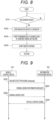
- step S102 the communication control unit 104 transmits a failure detection signal notifying that a failure has been detected to the information processing device 201 of the operation center 200 via the communication unit 102 and the network 300 ("failure detection signal (Announce)" in S201 of Fig. 9 ). Therefore, the display control unit 203 of the information processing device 201 receives the failure detection signal via the communication unit 202. Then, the display control unit 203 transmits a failure detection reception acknowledgment signal and a normal sensor information request signal to the communication control unit 104 that is a transmission source of the failure detection signal via the communication unit 202 and the network 300 ("normal sensor information request" in S202 of Fig. 9 ).
- step S103 the processing proceeds to step S103, and the communication control unit 104 waits until receiving the normal sensor information request signal from the information processing device 201. Then, when having received the normal sensor information request signal, the communication control unit 104 transmits the sensing data (hereinafter, also referred to as "normal sensor data") of the sensors 103 1 , ..., 103 i-1 , 103 i+1 , ..., and 103 N other than the sensor 103 i (i is any one of 1 to N) determined to have failed in step S101 among the sensors 103 1 , 103 2 , ..., and 103 N to the information processing device 201 of the operation center 200 via the communication unit 102 and the network 300 ("normal sensor data" in step S203 in Fig. 9 ).
- the sensing data hereinafter, also referred to as "normal sensor data"
- the transmission of the normal sensor data is continued until the remote driving is started. That is, the communication control unit 104 starts the transmission of the sensing data of the sensors other than the sensor determined to have failed to the information processing device 201. Note that it may be configured to start the transmission of the sensing data of the area around the vehicle 100 generated on the basis of the normal sensor data (the sensing data of the sensors other than the sensor determined to have failed) instead of the normal sensor data.
- the display control unit 203 of the information processing device 201 receives the sensing data via the communication unit 202, causes the display unit 204 to display the sensing result indicated by the received sensing data, and provides the operator of the information processing device 201 with a situation of the area around the vehicle 100.
- the operator operates the remote operation unit 205 so that the vehicle 100 moves to a safe place such as a roadside strip on the basis of the situation of the area around the vehicle 100 provided from the display unit 204. Then, the remote operation unit 205 transmits the operation information (vehicle control signal) related to the remote driving of the vehicle 100 to the communication control unit 104 as a transmission source of the sensing data via the communication unit 202 and the network 300 ("vehicle control signal" in S204 of Fig. 9 ).
- vehicle control signal vehicle control signal
- the communication control unit 104 performs control to transmit the sensing data including the image data of the remaining cameras to the information processing device 201 in a case where it is determined that any of the two or more cameras 103 1 , 103 2 , and 103 3 has failed. Therefore, even if one camera that captures an image of the front of the vehicle 100 fails, the display unit 204 can display an image of the front of the vehicle 100 on the display unit 204.
- the communication control unit 104 performs control to transmit the sensing data including the image data of the other camera to the information processing device 201 in a case where it is determined that one of the two cameras 103 4 and 103 5 has failed. Therefore, even if one camera that captures an image of the front of the vehicle 100 fails, the display unit 204 can display an image of the front of the vehicle 100 on the display unit 204.
- the communication control unit 104 converts the image data of the diagonally right front camera 103 7 and the image data of the diagonally left front camera 103e to generate the image data of the front of the vehicle 100 in a case where it is determined that the front camera 103 6 has failed. Then, the control is performed to transmit the generated image data to the information processing device 201.
- Examples of the image data of the front of the vehicle 100 include the image data obtained by capturing an image with the front camera 103 6 and image data obtained by capturing an image with a virtual front camera that captures an image of the front of the vehicle 100. Thereby, even if all the cameras (including the front camera 103 6 ) that captures an image of the front of the vehicle 100 fail, an image of the front of the vehicle 100 can be displayed on the display unit 204.
- the communication control unit 104 converts the image data of the right side camera 103 10 and the image data of the left side camera 103 1 , to generate the image data of the front of the vehicle 100 in a case where it is determined that the front camera 103 9 has failed.
- the image data of the front of the vehicle 100 include the image data obtained by capturing an image with the front camera 103 9 and image data obtained by capturing an image with a virtual front camera that captures an image of the front of the vehicle 100.
- step S104 the travel control unit 105 waits until receiving the vehicle control signal from the information processing device 201. Then, when having received the vehicle control signal, the travel control unit 105 terminates the automated driving and starts the remote driving.
- the travel control unit 105 controls the travel of the vehicle 100 on the basis of the vehicle control signal. Thereby, the operator can perform the remote driving of the vehicle 100. Therefore, the operator (remote driver) can move the vehicle 100 to a safe place such as a roadside strip by the remote driving.
- the vehicle control device 101 starts transmission of the sensing data of the sensors other than the sensor 103 i determined to have failed to the information processing device 201, or starts transmission of the sensing data of the area around the vehicle 100 generated on the basis of the sensing data to the information processing device 201. Therefore, for example, even in the case where any of the plurality of sensors 103 1 , 103 2 , ..., and 103 N has failed during travel control (automated driving) of the vehicle 100 based on the sensing data, it is possible to provide appropriate sensing data to the operator of the information processing device 201. Therefore, it is possible to cause the operator (remote driver) to perform the remote driving of the vehicle 100 on the basis of appropriate sensing data. Thereby, it is possible to move the vehicle 100 to a safe place such as a roadside strip by the remote driving.
- FIG. 10 is a diagram illustrating a flowchart of processing upon failure executed by the vehicle control device 101 according to the second embodiment.
- portions corresponding to those in Fig. 8 are denoted by the same reference numerals, and redundant description will be omitted.
- the second embodiment is different from the first embodiment in changing sensing data to be transmitted to an information processing device 201 according to the degree of failure of a sensor 103 i determined to have failed in the processing upon failure.
- the processing upon failure includes steps S301 to S313 instead of step S101 illustrated in Fig. 8 .
- sensors 103 1 and 103 3 include cameras 103 1 and 103 3 illustrated in Fig. 2 (front cameras having different angles of view and capturing an image of front of a vehicle 100 to generate image data).
- the camera 103 1 is a camera having a wider angle of view and a wider imaging range than the camera 103s, and thus functions as a camera that senses a vicinity.
- the camera 103 3 is a camera having a narrower angle of view and a narrower imaging range than the camera 103 1 , but capable of capturing a far place, and thus functions as a camera that senses a far distance.
- a communication control unit 104 acquires failure determination signals transmitted from failure detection units 107 1 , 107 2 , ..., and 107 N .
- the processing proceeds to step S302.
- this determination is executed again.
- step S302 the communication control unit 104 determines whether or not a traveling speed of the vehicle 100 has a predetermined value (a vehicle speed determined as "high-speed traveling", for example, 80 km/h) or more. Then, in a case where it is determined that the traveling speed is the predetermined value or more (Yes), the processing proceeds to step S303. On the other hand, in a case where it is determined that the traveling speed is less than the predetermined value (No), the processing proceeds to step S102.
- a predetermined value a vehicle speed determined as "high-speed traveling", for example, 80 km/h
- step S303 the communication control unit 104 determines whether or not the sensor 103 i determined to have failed in step S101 among the sensors 103 1 , 103 2 , ..., and 103 N is the camera 103 3 having the narrow angle of view or the camera 103 1 having the wide angle of view illustrated in Fig. 2 , or another sensor such as the camera 103 2 . Then, in a case where it is determined that the sensor 103 i is the camera 103 3 having the narrow angle of view (camera having a narrow angle of view), the processing proceeds to step S304. Furthermore, in a case where it is determined that the sensor 103 i is the camera 103 1 having the wide angle of view (camera having a wide angle of view), the processing proceeds to step S309. Meanwhile, in a case where the sensor 103 i is another sensor (others), the processing proceeds to step S102.
- step S304 the travel control unit 105 terminates automated driving and starts deceleration control for decelerating the vehicle 100.
- the deceleration control for example, minimum risk maneuver (MRM) that automatically stops the vehicle 100 can be adopted.
- MRM minimum risk maneuver
- the communication control unit 104 transmits a failure detection signal notifying that a failure has been detected to an information processing device 201 of an operation center 200 via a communication unit 102 and a network 300. Therefore, a display control unit 203 of the information processing device 201 receives the failure detection signal via the communication unit 202, and transmits a failure detection reception acknowledgment signal and a normal sensor information request signal to the communication control unit 104 that is a transmission source of the failure detection signal. The deceleration control is continued until remote driving is started.
- a travel control unit 105 starts the deceleration control of the vehicle 100 before transmission of sensing data to the information processing device 201. That is, the travel control unit 105 is configured to change a handover procedure of the remote driving to the information processing device 201 according to a type of the sensor determined to have failed.
- the image data of the camera 103 1 having a narrow angle of view (the camera that senses a far distance) is more important than the image data of the camera 103 3 having a wide angle of view (the camera that senses a close distance). Therefore, in a case where there is an abnormality in the image data of high importance (the image data of the camera 103 3 having a narrow angle of view), it is possible to terminate the automated driving (high-speed traveling), decelerate the vehicle 100, and hand over the remote driving to an operator.
- step S305 the processing proceeds to step S305, and the communication control unit 104 waits until receiving a normal sensor information request signal from the information processing device 201. Then, when having received the normal sensor information request signal, the communication control unit 104 determines whether or not the degree of abnormality of the sensing data of the sensor determined to have failed (the camera 103 3 illustrated in Fig. 2 ) exceeds a predetermined reference. For example, it is determined whether or not a missing amount of pixels in the image indicated by the image data of the camera 103 3 is a predetermined value (for example, 10%) or more, and in a case where it is determined that the missing amount is the predetermined value or more, it is determined that the missing amount exceeds the reference.
- a predetermined value for example, 10%
- a missing portion of pixels in the image indicated by the image data of the camera 103 3 is a predetermined portion (for example, a central portion of the image, a portion of a road surface of the image), and in a case where it is determined that the missing portion is the predetermined portion, it is determined that the missing portion exceeds the reference. Then, in the case where it is determined that the missing amount or the missing portion exceeds the reference (Yes), the processing proceeds to step S306. On the other hand, in the case where it is determined that the missing amount or the missing portion is the reference or less (No), the processing proceeds to step S307.
- a predetermined portion for example, a central portion of the image, a portion of a road surface of the image
- step S306 the communication control unit 104 transmits the sensing data of the sensors 103 1 , 103 2 , 103 4 , ..., and 103 N other than the sensor determined to have failed (the camera 103 3 illustrated in Fig. 2 ) among the sensors 103 1 , 103 2 , ..., and 103 N to the information processing device 201 of the operation center 200 via the communication unit 102 and the network 300, and then proceeds to step S308.
- the transmission of the sensing data is continued until the remote driving is started. That is, the communication control unit 104 performs control to transmit the sensing data including the image data of the cameras other than the camera 103 3 determined to have failed to the information processing device 201.
- step S307 the communication control unit 104 transmits the sensing data of all the sensors 103 1 , 103 2 , ..., and 103 N (including the camera 103 3 ) to the information processing device 201 of the operation center 200 via the communication unit 102 and the network 300, and then proceeds to step S308.
- the transmission of the sensing data is continued until the remote driving is started. That is, the communication control unit 104 performs control to transmit the sensing data including the image data of the camera 103 3 determined to have failed to the information processing device 201.
- step S305 the communication control unit 104 determines whether or not the missing amount of pixels in the image indicated by the image data of the camera 103 3 determined to have failed is the predetermined value (for example, 10%) or more. Then, in the case of determining that the missing amount is the predetermined value or more ("Yes" in step S305), in step S306, the communication control unit 104 performs control to transmit the sensing data not including the image data of the camera 103 3 to the information processing device 201.
- the predetermined value for example, 10%
- step S307 the communication control unit 104 performs control to transmit the sensing data (including the image data of the camera 103 3 ) of all the sensors 103 1 , 103 2 , ... and 103 N to the information processing device 201.
- the sensing data including the image data having a missing pixel is transmitted.
- step S305 the communication control unit 104 determines whether or not the missing portion of pixels in the image indicated by the image data of the camera 103 3 determined to have failed is the predetermined portion.
- the predetermined portion include a central portion of the image or a portion of a road surface in the image. Then, in the case of determining that the missing portion is the predetermined portion ("Yes" in step S305), in step S306, the communication control unit 104 performs control to transmit the sensing data not including the image data of the camera 103 3 to the information processing device 201.
- step S307 the communication control unit 104 performs control to transmit the sensing data (including the image data of the camera 103 3 ) of all the sensors 103 1 , 103 2 , ... and 103 N to the information processing device 201.
- the sensing data including the image data of a missing pixel is transmitted.
- the communication control unit 104 is configured to change the sensing data to be transmitted to the information processing device 201 according to the degree of failure (the missing amount of pixels or the missing portion of pixels) of the sensor (camera 103 3 ) determined to have failed.
- step S308 and the travel control unit 105 waits until receiving a vehicle control signal from the information processing device 201. Then, when having received the vehicle control signal, the travel control unit 105 terminates the deceleration control, starts the remote driving on the basis of the vehicle control signal, and then terminates the processing upon failure. Therefore, the operator can perform the remote driving of the vehicle 100, and the operator can move the vehicle 100 to a safe place such as a roadside strip by the remote driving.
- step S309 the communication control unit 104 transmits the failure detection signal notifying that a failure has been detected to the information processing device 201 of the operation center 200 via the communication unit 102 and the network 300. Therefore, the display control unit 203 of the information processing device 201 receives the failure detection signal via the communication unit 202, and transmits the failure detection reception acknowledgment signal and the normal sensor information request signal to the communication control unit 104 that is a transmission source of the failure detection signal.
- step S310 the processing proceeds to step S310, and the communication control unit 104 waits until receiving a normal sensor information request signal from the information processing device 201. Then, when having received the normal sensor information request signal, the communication control unit 104 determines whether or not the degree of abnormality of the sensing data of the sensor determined to have failed (the camera 103 1 illustrated in Fig. 2 ) exceeds a predetermined reference. Then, in the case where it is determined that the degree of abnormality exceeds the reference (Yes), the processing proceeds to step S311. On the other hand, in the case where it is determined that the degree of abnormality is the reference or less (No), the processing proceeds to step S312.
- step S311 the communication control unit 104 transmits the sensing data of the sensors 103 2 , ..., and 103 N other than the sensor determined to have failed (the camera 103 1 illustrated in Fig. 2 ) among the sensors 103 1 , 103 2 , ..., and 103 N to the information processing device 201 of the operation center 200 via the communication unit 102 and the network 300, and then proceeds to step S313.
- the transmission of the sensing data is continued until the remote driving is started. That is, the communication control unit 104 performs control to transmit the sensing data including the image data of the cameras other than the camera 103 1 determined to have failed to the information processing device 201.
- step S312 the communication control unit 104 transmits the sensing data of all the sensors 103 1 , 103 2 , ..., and 103 N (including the camera 103 1 ) to the information processing device 201 of the operation center 200 via the communication unit 102 and the network 300, and then proceeds to step S313.
- the transmission of the sensing data is continued until the remote driving is started. That is, the communication control unit 104 performs control to transmit the sensing data including the image data of the camera 103 1 determined to have failed to the information processing device 201.
- step S313 after transmitting the sensing data to the information processing device 201, the communication control unit 104 determines whether or not a response indicating the start of the remote driving has been received from the information processing device 201 within a predetermined period (for example, 10 seconds).
- a response indicating the start of the remote driving for example, a signal for notifying the start of the remote driving and the vehicle control signal can be adopted.
- An example of the signal for notifying the start of the remote driving includes a signal transmitted from the information processing device 201 when the operator presses a button for switching the automated driving to the remote driving.
- step S314 and the travel control unit 105 waits until receiving the vehicle control signal from the information processing device 201. Then, when having received the vehicle control signal, the travel control unit 105 terminates the automated driving, starts the remote driving on the basis of the vehicle control signal, and then terminates the processing upon failure. Therefore, the operator can perform the remote driving of the vehicle 100, and the operator can move the vehicle 100 to a safe place such as a roadside strip by the remote driving.
- the travel control unit 105 maintains the automated driving until the remote driving is started. That is, the travel control unit 105 is configured to change the handover procedure of the remote driving to the information processing device 201 according to the type of the sensor determined to have failed.
- the image data of the camera 103 1 having the narrow angle of view (the camera that senses a far distance) is more important than the image data of the camera 103 3 having the wide angle of view (the camera that senses a close distance). Therefore, in a case where there is no abnormality in the image data of high importance (the image data of the camera 103 3 having the narrow angle of view), it is possible to continue the automated driving (high-speed traveling) and hand over the remote driving to the operator.
- step S315 the travel control unit 105 starts the deceleration control (for example, MRM) for decelerating the vehicle 100, and then terminates the processing upon failure.
- the deceleration control for example, MRM
- the vehicle deceleration control can be started to decelerate and stop the vehicle 100.
- the present technology may also have the following configuration.
Landscapes
- Engineering & Computer Science (AREA)
- General Physics & Mathematics (AREA)
- Physics & Mathematics (AREA)
- Automation & Control Theory (AREA)
- Remote Sensing (AREA)
- Aviation & Aerospace Engineering (AREA)
- Radar, Positioning & Navigation (AREA)
- Life Sciences & Earth Sciences (AREA)
- Atmospheric Sciences (AREA)
- Analytical Chemistry (AREA)
- Chemical & Material Sciences (AREA)
- Human Computer Interaction (AREA)
- Transportation (AREA)
- Mechanical Engineering (AREA)
- Traffic Control Systems (AREA)
Abstract
Description
- The present disclosure relates to a vehicle control device, a vehicle control system, and a vehicle control method.
- Conventionally, there has been proposed a vehicle failure notification device that is mounted on a vehicle, detects a failure of an electronic component in the vehicle, and notifies information notifying a location or a degree of the failure to a notification destination (an emergency center, a support sensor, a normal call center, or the like) according to characteristics of the failure (see, for example, Patent Document 1).
- Patent Document 1:
Japanese Patent Application Laid-Open No. 2006-23851 - However,
Patent Document 1 does not disclose a configuration that enables the vehicle to move to a safe place in the case where a sensor used for automated driving fails during the automated driving. - An object of the present disclosure is to provide a vehicle control device, a vehicle control system, and a vehicle control method capable of moving a vehicle to a safe place in a case where a sensor used for automated driving fails during the automated driving.
- A vehicle control device of the present disclosure includes (a) a plurality of sensors mounted on a vehicle and configured to sense an area around the vehicle to generate sensing data, (b) a travel control unit mounted on the vehicle and configured to selectively execute automated driving that controls travel of the vehicle on a basis of the sensing data of the plurality of sensors and remote driving that controls travel of the vehicle on a basis of operation information related to the remote driving of the vehicle transmitted from an external device, and (c) a communication control unit mounted on the vehicle, and configured to, in a case where it is determined that any of the plurality of sensors has failed during the automated driving, start transmission of the sensing data of the sensor other than the sensor determined to have failed to the external device, or start transmission of sensing data of the area around the vehicle generated on a basis of the sensing data to the external device.
- A vehicle control system of the present disclosure includes (a) a vehicle control device mounted on a vehicle, and (b) an external device disposed outside the vehicle, the vehicle control device including (c) a plurality of sensors configured to sense an area around the vehicle to generate sensing data, (d) a travel control unit configured to selectively execute automated driving that controls travel of the vehicle on a basis of the sensing data of the plurality of sensors and remote driving that controls travel of the vehicle on a basis of operation information related to the remote driving of the vehicle transmitted from the external device, and (e) a communication control unit configured to, in a case where it is determined that any of the plurality of sensors has failed during the automated driving, start transmission of the sensing data of the sensor other than the sensor determined to have failed to the external device, or start transmission of sensing data of the area around the vehicle generated on a basis of the sensing data to the external device, and the external device including (f) a display unit configured to display an image related to an area around the vehicle on a basis of the sensing data, and (g) a remote operation unit configured to receive an operation by a remote driver, generate the operation information according to the received operation, and transmit the operation information to the external device.
- A vehicle control method of the present disclosure includes (a) selectively executing automated driving that controls travel of a vehicle on a basis of sensing data generated by a plurality of sensors mounted on the vehicle or remote driving that controls travel of the vehicle on a basis of operation information related to the remote driving of the vehicle transmitted from an external device, and (b) in a case where it is determined that any of the plurality of sensors mounted on the vehicle has failed during the automated driving, starting transmission of the sensing data of the sensor other than the sensor determined to have failed to the external device, or starting transmission of sensing data of the area around the vehicle generated on a basis of the sensing data to the external device.
-
-
Fig. 1 is a diagram illustrating an overall configuration of a vehicle control system according to a first embodiment. -
Fig. 2 is a diagram illustrating an example of a sensor. -
Fig. 3 is a diagram illustrating an example of a sensor. -
Fig. 4 is a diagram illustrating an example of a sensor. -
Fig. 5 is a diagram illustrating an example of a sensor. -
Fig. 6 is a diagram illustrating an internal configuration of a communication control unit. -
Fig. 7 is a diagram illustrating an overall configuration of an information processing device. -
Fig. 8 is a diagram illustrating a flowchart of processing upon failure. -
Fig. 9 is a diagram illustrating communication in a vehicle control system. -
Fig. 10 is a diagram illustrating a flowchart of processing upon failure according to a second embodiment. - Hereinafter, an example of a vehicle control device, a vehicle control system, and a vehicle control method according to an embodiment of the present disclosure will be described with reference to
Figs. 1 to 10 . Embodiments of the present disclosure will be described in the following order. Note that, the present disclosure is not limited to the following examples. Furthermore, the effects described in the present specification are illustrative and not restrictive, and there may be additional effects. -
- 1. First Embodiment
- 1-1 Vehicle Control System
- 1-2 Processing Upon Failure
- 2. Second Embodiment
- A
vehicle control system 1000 according to a first embodiment of the present disclosure will be described.Fig. 1 is a diagram illustrating an overall configuration of thevehicle control system 1000 according to the first embodiment. Thevehicle control system 1000 is a system in which, in a case where it is determined that any of sensors has failed during automated driving, a vehicle side transmits sensing data of a sensor other than the sensor determined to have failed to an external device (hereinafter, also referred to as an "information processing device"), and the information processing device side presents the transmitted sensing data to an operator and causes the operator perform remote driving of the vehicle. Therefore, the vehicle can be moved to a safe place by the remote driving of the operator. - As illustrated in
Fig. 1 , thevehicle control system 1000 includes avehicle control device 101 mounted on avehicle 100 and aninformation processing device 201 installed in anoperation center 200. Thevehicle control device 101 and theinformation processing device 201 are wirelessly connected via anetwork 300. An example of thenetwork 300 includes the Internet using a communication protocol such as TCP/IP. - The
vehicle 100 on which thevehicle control device 101 is mounted is a moving object capable of automated driving based on sensing data obtained by sensing an area around the vehicle and remote driving by a remote operator. A person may or may not be on thevehicle 100. - The
vehicle control device 101 includes acommunication unit 102, a plurality ofsensors communication control unit 104, and atravel control unit 105. - The
communication unit 102 wirelessly communicates with the external device such as theinformation processing device 201 via thenetwork 300. Furthermore, communication of thecommunication unit 102 is controlled by thecommunication control unit 104. An example of thecommunication unit 102 includes a combination of a communication antenna and an RF circuit. - As illustrated in
Figs. 2 ,3 ,4 , and5 , thesensors vehicle 100 to generate the sensing data. As thesensors vehicle 100 to generate image data. The sensing data (image data) is output to thecommunication control unit 104. -
Fig. 2 exemplifies a case where thesensors more cameras camera 1031 is a front camera that is disposed near an upper portion of a windshield of thevehicle 100, has the first angle of view α1, and captures an image of the front of thevehicle 100. Furthermore, thecamera 1032 is a front camera that is disposed near a front grille of thevehicle 100, has the second angle of view α2 narrower than the first angle of view α1, and captures an image of the front of thevehicle 100. Furthermore, thecamera 1033 is a front camera that is disposed near the front grille of thevehicle 100, has the third angle of view α3 narrower than the second angle of view α2, and captures an image of the front of thevehicle 100. Furthermore, thecameras camera 1031, an imaging range 1062 of thecamera 1032, and an imaging range 1063 of thecamera 1033 overlap each other. That is, the imaging ranges 1061, 1062, and 1063 partially overlap each other. - Note that the imaging ranges 1061, 1062, and 1063 illustrated in
Fig. 2 are given for indicating the first to third angles of view α1, α2, and α3. Therefore, ends (hereinafter, also referred to as "far-side ends") of the imaging ranges 1061, 1062, and 1063 illustrated inFig. 2 on a side far from thevehicle 100 are located relatively close to thevehicle 100 for convenience of drawing. However, in practice, the far-side ends are located sufficiently far from thevehicle 100, and the imaging ranges 1061, 1062, and 1063 sufficiently overlap each other. Furthermore, the same similarly applies to imaging ranges 1064, 1065, 1066, 1067, 1068, 1069, 10610, and 10611 illustrated inFigs. 3 ,4 , and5 . -
Fig. 3 exemplifies a case wheresensors 1034 and 103s include twocameras 1034 and 103s having angles of view α4 and α5 that are the same and capturing images in the same direction to generate the image data (sensing data). Specifically, thecamera 1034 is a front camera that is disposed near a lower portion of the windshield of thevehicle 100, has the fourth angle of view α4, and captures an image of the front of thevehicle 100. Furthermore, thecamera 1035 is a front camera that is disposed near a lower portion of the windshield of thevehicle 100, has the fifth angle of view α5 (= α4) equal to the fourth angle of view α4, and captures an image of the front of thevehicle 100. Furthermore, thecamera 1034 and the camera 103s are arranged side by side at close positions in the vehicle width direction in plan view. Therefore, most of areas of the imaging range 1064 of thecamera 1034 and the imaging range 1064 of thecamera 1034 overlap each other. That is, the imaging ranges 1064 and 1064 partially overlap each other. As thecamera 1034 and the camera 103s, for example, two monocular cameras constituting a redundant system in which one serves as the other's reserve device can be adopted. Furthermore, for example, a stereo camera can be adopted. -
Fig. 4 illustrates a case wheresensors front camera 1036, a diagonally rightfront camera 1037, and a diagonally leftfront camera 1038 that capture images in different directions to generate the image data (sensing data). Specifically, thefront camera 1036 is disposed near a lower portion of the windshield of thevehicle 100 and captures an image of the front of thevehicle 100. Furthermore, the diagonally rightfront camera 1037 is disposed near a diagonally right front end of thevehicle 100, and captures an image of the diagonally right front of thevehicle 100. Furthermore, the diagonally left front camera 103e is disposed near a diagonally left front end of thevehicle 100, and captures an image of the diagonally left front of thevehicle 100. Furthermore, areas on the end side of the imaging range 1067 of the diagonally rightfront camera 1037 and the imaging range 106e of the diagonally leftfront camera 1035 overlaps the imaging range 1066 of thefront camera 1036. That is, the imaging ranges 1067 and 1068 partially overlap the imaging range 1066. -
Fig. 5 illustrates a case wheresensors front camera 1039, aright side camera 10310, and aleft side camera 10311 that capture images in different directions to generate the image data (sensing data). Specifically, thefront camera 1039 is disposed near a lower portion of the windshield of thevehicle 100 and captures an image of the front of thevehicle 100. Furthermore, theright side camera 10310 is disposed near a right-side door mirror of thevehicle 100, and captures an image of a right side of thevehicle 100. Furthermore, theleft side camera 10311 is disposed near a left-side door mirror of thevehicle 100, and captures an image of a left side of thevehicle 100. Furthermore, areas on the end side of the imaging range 10610 of theright side camera 10310 and the imaging range 10611 of theleft side camera 10311 overlaps the imaging range 1069 of thefront camera 1039. That is, the imaging ranges 10610 and 10611 partially overlap the imaging range 1069. - Furthermore, the
sensors sensors communication control unit 104. - As illustrated in
Fig. 6 , thecommunication control unit 104 includes aprocessor 150, aROM 151, aRAM 152, and arecording medium 153. Furthermore, in thevehicle control device 101, the components are connected to each other via abus 154 as a transmission path for data or the like. - The
processor 150 includes, for example, one or more processors including an arithmetic circuit such as a micro processing unit (MPU), various processing circuits, and the like, and controls theentire vehicle 100. Furthermore, theprocessor 150 functions as thevehicle control device 101 that performs processing (hereinafter, also referred to as "processing upon failure") related to a vehicle control method according to the first embodiment together with thetravel control unit 105. Note that the processing related to the vehicle control method may be performed by a dedicated circuit (for example, a processor separate from the processor 150) or a general-purpose circuit capable of realizing the processing upon failure. - The
ROM 151 stores control data such as programs and operation parameters used by theprocessor 150. Furthermore, theRAM 152 temporarily stores programs and the like executed by theprocessor 150. Furthermore, therecording medium 153 stores, for example, data, various applications, and the like related to the processing upon failure to be described below. Examples of therecording medium 153 include a magnetic recording medium such as a hard disk, and a nonvolatile memory such as a flash memory. Note that therecording medium 153 may be detachable from thevehicle control device 101. - The
travel control unit 105 can selectively execute automated driving, remote driving, and deceleration control of thevehicle 100. In the automated driving, thetravel control unit 105 controls the travel of thevehicle 100 on the basis of the sensing data of the plurality ofsensors travel control unit 105 controls a driving force, a braking/driving force, a steering angle, and the like of wheels so that thevehicle 100 travels following a preceding vehicle while maintaining a lane. Furthermore, in the remote driving, thetravel control unit 105 controls the travel of thevehicle 100 on the basis of operation information (hereinafter, also referred to as a "vehicle control signal") regarding the remote driving of thevehicle 100 transmitted from theinformation processing device 201. For example, thetravel control unit 105 controls the driving force, the braking/driving force, the steering angle, and the like of the wheels so that thevehicle 100 travels according to the remote driving by a remote driver. Furthermore, in the deceleration control, thetravel control unit 105 decelerates thevehicle 100. For example, thetravel control unit 105 controls the driving force, the braking/driving force, the steering angle, and the like of the wheels on the basis of the sensing data of the plurality ofsensors vehicle 100 safely decelerates and stops. - Furthermore, as will be described below, the
travel control unit 105 executes the processing upon failure together with thecommunication control unit 104, and switches the automated driving to the remote driving or the deceleration control by the processing upon failure. - Returning to
Fig. 1 , theoperation center 200 in which theinformation processing device 201 is disposed is a data center in which the operator who performs the remote driving of thevehicle 100 at the time of sensor failure is resident. - As illustrated in
Figs. 1 and7 , theinformation processing device 201 includes acommunication unit 202, adisplay control unit 203, adisplay unit 204, and aremote operation unit 205. - The
communication unit 202 wirelessly communicates with thevehicle control device 101 of thevehicle 100 via thenetwork 300. Furthermore, communication of thecommunication unit 202 is controlled by theremote operation unit 205. An example of thecommunication unit 202 includes a combination of a communication antenna and an RF circuit. - The
display control unit 203 receives the sensing data from thevehicle control device 101 via thecommunication unit 202, and causes thedisplay unit 204 to display a sensing result indicated by the received sensing data.Fig. 7 illustrates a case where three liquid crystal displays (multi-displays) are used as thedisplay unit 204. In the case where three liquid crystal displays are used, for example, the image data of the camera that captures an image of the front of the vehicle is displayed on the central liquid crystal display, furthermore, the image data of the camera that captures an image of the left side of the vehicle is displayed on the left liquid crystal display, and moreover, the image data of the camera that captures an image of the right side of the vehicle is displayed on the right liquid crystal display. - The
remote operation unit 205 is a controller imitating an accelerator pedal, a brake pedal, and a steering wheel. Then, theremote operation unit 205 receives an operation by the operator (remote driver), generates the operation information (vehicle control signal) according to the received operation, and transmits the operation information to thecommunication control unit 104 of thevehicle 100 via thecommunication unit 202 and thenetwork 300. - Next, the processing upon failure executed by the
communication control unit 104 and thetravel control unit 105 will be described. The processing upon failure is executed when thetravel control unit 105 starts the automated driving. Note that, during the execution of the processing upon failure, the automated driving is continued until the remote driving or the deceleration control is started. - In the processing upon failure, as illustrated in
Fig. 8 , first, in step S101, thecommunication control unit 104 acquires the failure determination signals transmitted from the failure detection units 1071, 1072, ..., and 107N. Next, it is determined whether or not any of the plurality ofsensors - In step S102, the
communication control unit 104 transmits a failure detection signal notifying that a failure has been detected to theinformation processing device 201 of theoperation center 200 via thecommunication unit 102 and the network 300 ("failure detection signal (Announce)" in S201 ofFig. 9 ). Therefore, thedisplay control unit 203 of theinformation processing device 201 receives the failure detection signal via thecommunication unit 202. Then, thedisplay control unit 203 transmits a failure detection reception acknowledgment signal and a normal sensor information request signal to thecommunication control unit 104 that is a transmission source of the failure detection signal via thecommunication unit 202 and the network 300 ("normal sensor information request" in S202 ofFig. 9 ). - Next, the processing proceeds to step S103, and the
communication control unit 104 waits until receiving the normal sensor information request signal from theinformation processing device 201. Then, when having received the normal sensor information request signal, thecommunication control unit 104 transmits the sensing data (hereinafter, also referred to as "normal sensor data") of thesensors 1031, ..., 103i-1, 103i+1, ..., and 103N other than the sensor 103i (i is any one of 1 to N) determined to have failed in step S101 among thesensors information processing device 201 of theoperation center 200 via thecommunication unit 102 and the network 300 ("normal sensor data" in step S203 inFig. 9 ). The transmission of the normal sensor data is continued until the remote driving is started. That is, thecommunication control unit 104 starts the transmission of the sensing data of the sensors other than the sensor determined to have failed to theinformation processing device 201. Note that it may be configured to start the transmission of the sensing data of the area around thevehicle 100 generated on the basis of the normal sensor data (the sensing data of the sensors other than the sensor determined to have failed) instead of the normal sensor data. - Thereby, the
display control unit 203 of theinformation processing device 201 receives the sensing data via thecommunication unit 202, causes thedisplay unit 204 to display the sensing result indicated by the received sensing data, and provides the operator of theinformation processing device 201 with a situation of the area around thevehicle 100. - Furthermore, the operator operates the
remote operation unit 205 so that thevehicle 100 moves to a safe place such as a roadside strip on the basis of the situation of the area around thevehicle 100 provided from thedisplay unit 204. Then, theremote operation unit 205 transmits the operation information (vehicle control signal) related to the remote driving of thevehicle 100 to thecommunication control unit 104 as a transmission source of the sensing data via thecommunication unit 202 and the network 300 ("vehicle control signal" in S204 ofFig. 9 ). - For example, in a case where two or more cameras (in
Fig. 2 , the threecameras Fig. 2 are included as thesensors communication control unit 104 performs control to transmit the sensing data including the image data of the remaining cameras to theinformation processing device 201 in a case where it is determined that any of the two ormore cameras vehicle 100 fails, thedisplay unit 204 can display an image of the front of thevehicle 100 on thedisplay unit 204. - Furthermore, for example, in a case where the two
cameras 1034 and 103s illustrated inFig. 3 (for example, a stereo camera or two monocular cameras constituting a redundant system) are included as thesensors communication control unit 104 performs control to transmit the sensing data including the image data of the other camera to theinformation processing device 201 in a case where it is determined that one of the twocameras vehicle 100 fails, thedisplay unit 204 can display an image of the front of thevehicle 100 on thedisplay unit 204. - Furthermore, for example, in a case where the
front camera 1036, the diagonally rightfront camera 1037, and the diagonally leftfront camera 1038 illustrated inFig. 4 are included as thesensors communication control unit 104 converts the image data of the diagonally rightfront camera 1037 and the image data of the diagonally left front camera 103e to generate the image data of the front of thevehicle 100 in a case where it is determined that thefront camera 1036 has failed. Then, the control is performed to transmit the generated image data to theinformation processing device 201. Examples of the image data of the front of thevehicle 100 include the image data obtained by capturing an image with thefront camera 1036 and image data obtained by capturing an image with a virtual front camera that captures an image of the front of thevehicle 100. Thereby, even if all the cameras (including the front camera 1036) that captures an image of the front of thevehicle 100 fail, an image of the front of thevehicle 100 can be displayed on thedisplay unit 204. - Furthermore, for example, in a case where the
front camera 1039, theright side camera 10310, and theleft side camera 10311 illustrated inFig. 5 are included as thesensors communication control unit 104 converts the image data of theright side camera 10310 and the image data of theleft side camera 1031, to generate the image data of the front of thevehicle 100 in a case where it is determined that thefront camera 1039 has failed. Examples of the image data of the front of thevehicle 100 include the image data obtained by capturing an image with thefront camera 1039 and image data obtained by capturing an image with a virtual front camera that captures an image of the front of thevehicle 100. Thereby, even if all the cameras (including the front camera 1039) that capture an image of the front of thevehicle 100 fail, an image of the front of thevehicle 100 can be displayed on thedisplay unit 204. - Next, the processing proceeds to step S104, and the
travel control unit 105 waits until receiving the vehicle control signal from theinformation processing device 201. Then, when having received the vehicle control signal, thetravel control unit 105 terminates the automated driving and starts the remote driving. In the remote driving, thetravel control unit 105 controls the travel of thevehicle 100 on the basis of the vehicle control signal. Thereby, the operator can perform the remote driving of thevehicle 100. Therefore, the operator (remote driver) can move thevehicle 100 to a safe place such as a roadside strip by the remote driving. - As described above, in the case where it is determined that any of the plurality of
sensors vehicle control device 101 according to the first embodiment starts transmission of the sensing data of the sensors other than thesensor 103i determined to have failed to theinformation processing device 201, or starts transmission of the sensing data of the area around thevehicle 100 generated on the basis of the sensing data to theinformation processing device 201. Therefore, for example, even in the case where any of the plurality ofsensors vehicle 100 based on the sensing data, it is possible to provide appropriate sensing data to the operator of theinformation processing device 201. Therefore, it is possible to cause the operator (remote driver) to perform the remote driving of thevehicle 100 on the basis of appropriate sensing data. Thereby, it is possible to move thevehicle 100 to a safe place such as a roadside strip by the remote driving. - Next, a
vehicle control system 1000, avehicle control device 101, and a vehicle control method according to a second embodiment of the present disclosure will be described. An overall configuration of thevehicle control system 1000 according to the second embodiment is similar to that inFig. 1 , and thus illustration thereof is omitted.Fig. 10 is a diagram illustrating a flowchart of processing upon failure executed by thevehicle control device 101 according to the second embodiment. InFig. 10 , portions corresponding to those inFig. 8 are denoted by the same reference numerals, and redundant description will be omitted. - The second embodiment is different from the first embodiment in changing sensing data to be transmitted to an
information processing device 201 according to the degree of failure of asensor 103i determined to have failed in the processing upon failure. Specifically, as illustrated inFig. 10 , the processing upon failure includes steps S301 to S313 instead of step S101 illustrated inFig. 8 . Furthermore,sensors cameras Fig. 2 (front cameras having different angles of view and capturing an image of front of avehicle 100 to generate image data). Here, thecamera 1031 is a camera having a wider angle of view and a wider imaging range than the camera 103s, and thus functions as a camera that senses a vicinity. Furthermore, thecamera 1033 is a camera having a narrower angle of view and a narrower imaging range than thecamera 1031, but capable of capturing a far place, and thus functions as a camera that senses a far distance. - In step S301, a
communication control unit 104 acquires failure determination signals transmitted from failure detection units 1071, 1072, ..., and 107N. Next, it is determined whether or not any of a plurality ofsensors - In step S302, the
communication control unit 104 determines whether or not a traveling speed of thevehicle 100 has a predetermined value (a vehicle speed determined as "high-speed traveling", for example, 80 km/h) or more. Then, in a case where it is determined that the traveling speed is the predetermined value or more (Yes), the processing proceeds to step S303. On the other hand, in a case where it is determined that the traveling speed is less than the predetermined value (No), the processing proceeds to step S102. - In step S303, the
communication control unit 104 determines whether or not thesensor 103i determined to have failed in step S101 among thesensors camera 1033 having the narrow angle of view or thecamera 1031 having the wide angle of view illustrated inFig. 2 , or another sensor such as thecamera 1032. Then, in a case where it is determined that thesensor 103i is thecamera 1033 having the narrow angle of view (camera having a narrow angle of view), the processing proceeds to step S304. Furthermore, in a case where it is determined that thesensor 103i is thecamera 1031 having the wide angle of view (camera having a wide angle of view), the processing proceeds to step S309. Meanwhile, in a case where thesensor 103i is another sensor (others), the processing proceeds to step S102. - In step S304, the
travel control unit 105 terminates automated driving and starts deceleration control for decelerating thevehicle 100. As the deceleration control, for example, minimum risk maneuver (MRM) that automatically stops thevehicle 100 can be adopted. Next, thecommunication control unit 104 transmits a failure detection signal notifying that a failure has been detected to aninformation processing device 201 of anoperation center 200 via acommunication unit 102 and anetwork 300. Therefore, adisplay control unit 203 of theinformation processing device 201 receives the failure detection signal via thecommunication unit 202, and transmits a failure detection reception acknowledgment signal and a normal sensor information request signal to thecommunication control unit 104 that is a transmission source of the failure detection signal. The deceleration control is continued until remote driving is started. - As described above, in steps S302 to S304, in a case of determining that the traveling speed of the
vehicle 100 is the predetermined value or more and thecamera 1033 having a narrow angle of view of the twocameras 1031 and 1033 (front cameras) has failed during the automated driving, atravel control unit 105 starts the deceleration control of thevehicle 100 before transmission of sensing data to theinformation processing device 201. That is, thetravel control unit 105 is configured to change a handover procedure of the remote driving to theinformation processing device 201 according to a type of the sensor determined to have failed. Here, in the automated driving at the time of high-speed traveling, the image data of thecamera 1031 having a narrow angle of view (the camera that senses a far distance) is more important than the image data of thecamera 1033 having a wide angle of view (the camera that senses a close distance). Therefore, in a case where there is an abnormality in the image data of high importance (the image data of thecamera 1033 having a narrow angle of view), it is possible to terminate the automated driving (high-speed traveling), decelerate thevehicle 100, and hand over the remote driving to an operator. - Next, the processing proceeds to step S305, and the
communication control unit 104 waits until receiving a normal sensor information request signal from theinformation processing device 201. Then, when having received the normal sensor information request signal, thecommunication control unit 104 determines whether or not the degree of abnormality of the sensing data of the sensor determined to have failed (thecamera 1033 illustrated inFig. 2 ) exceeds a predetermined reference. For example, it is determined whether or not a missing amount of pixels in the image indicated by the image data of thecamera 1033 is a predetermined value (for example, 10%) or more, and in a case where it is determined that the missing amount is the predetermined value or more, it is determined that the missing amount exceeds the reference. Furthermore, for example, it is determined whether or not a missing portion of pixels in the image indicated by the image data of thecamera 1033 is a predetermined portion (for example, a central portion of the image, a portion of a road surface of the image), and in a case where it is determined that the missing portion is the predetermined portion, it is determined that the missing portion exceeds the reference. Then, in the case where it is determined that the missing amount or the missing portion exceeds the reference (Yes), the processing proceeds to step S306. On the other hand, in the case where it is determined that the missing amount or the missing portion is the reference or less (No), the processing proceeds to step S307. - In step S306, the
communication control unit 104 transmits the sensing data of thesensors camera 1033 illustrated inFig. 2 ) among thesensors information processing device 201 of theoperation center 200 via thecommunication unit 102 and thenetwork 300, and then proceeds to step S308. The transmission of the sensing data is continued until the remote driving is started. That is, thecommunication control unit 104 performs control to transmit the sensing data including the image data of the cameras other than thecamera 1033 determined to have failed to theinformation processing device 201. - On the other hand, in step S307, the
communication control unit 104 transmits the sensing data of all thesensors information processing device 201 of theoperation center 200 via thecommunication unit 102 and thenetwork 300, and then proceeds to step S308. The transmission of the sensing data is continued until the remote driving is started. That is, thecommunication control unit 104 performs control to transmit the sensing data including the image data of thecamera 1033 determined to have failed to theinformation processing device 201. - As an example of steps S305 to S307, for example, first, in step S305, the
communication control unit 104 determines whether or not the missing amount of pixels in the image indicated by the image data of thecamera 1033 determined to have failed is the predetermined value (for example, 10%) or more. Then, in the case of determining that the missing amount is the predetermined value or more ("Yes" in step S305), in step S306, thecommunication control unit 104 performs control to transmit the sensing data not including the image data of thecamera 1033 to theinformation processing device 201. On the other hand, in the case of determining that the missing amount is less than the predetermined value ("No" in step S305), in step S307, thecommunication control unit 104 performs control to transmit the sensing data (including the image data of the camera 1033) of all thesensors information processing device 201. Thereby, in a case where the missing amount of the pixels is low and visibility is not degraded, the sensing data including the image data having a missing pixel is transmitted. - Furthermore, as another example, for example, first, in step S305, the
communication control unit 104 determines whether or not the missing portion of pixels in the image indicated by the image data of thecamera 1033 determined to have failed is the predetermined portion. Examples of the predetermined portion include a central portion of the image or a portion of a road surface in the image. Then, in the case of determining that the missing portion is the predetermined portion ("Yes" in step S305), in step S306, thecommunication control unit 104 performs control to transmit the sensing data not including the image data of thecamera 1033 to theinformation processing device 201. On the other hand, in the case of determining that the missing portion is less than the predetermined portion ("No" in step S305), in step S307, thecommunication control unit 104 performs control to transmit the sensing data (including the image data of the camera 1033) of all thesensors information processing device 201. Thereby, in the case where the visibility is not degraded, such as a case where the missing portion of pixels is small or a case where there is no obstacle, the sensing data including the image data of a missing pixel is transmitted. - As described above, in steps S305 to S307, the
communication control unit 104 is configured to change the sensing data to be transmitted to theinformation processing device 201 according to the degree of failure (the missing amount of pixels or the missing portion of pixels) of the sensor (camera 1033) determined to have failed. - In step S308, and the
travel control unit 105 waits until receiving a vehicle control signal from theinformation processing device 201. Then, when having received the vehicle control signal, thetravel control unit 105 terminates the deceleration control, starts the remote driving on the basis of the vehicle control signal, and then terminates the processing upon failure. Therefore, the operator can perform the remote driving of thevehicle 100, and the operator can move thevehicle 100 to a safe place such as a roadside strip by the remote driving. - In step S309, the
communication control unit 104 transmits the failure detection signal notifying that a failure has been detected to theinformation processing device 201 of theoperation center 200 via thecommunication unit 102 and thenetwork 300. Therefore, thedisplay control unit 203 of theinformation processing device 201 receives the failure detection signal via thecommunication unit 202, and transmits the failure detection reception acknowledgment signal and the normal sensor information request signal to thecommunication control unit 104 that is a transmission source of the failure detection signal. - Next, the processing proceeds to step S310, and the
communication control unit 104 waits until receiving a normal sensor information request signal from theinformation processing device 201. Then, when having received the normal sensor information request signal, thecommunication control unit 104 determines whether or not the degree of abnormality of the sensing data of the sensor determined to have failed (thecamera 1031 illustrated inFig. 2 ) exceeds a predetermined reference. Then, in the case where it is determined that the degree of abnormality exceeds the reference (Yes), the processing proceeds to step S311. On the other hand, in the case where it is determined that the degree of abnormality is the reference or less (No), the processing proceeds to step S312. - In step S311, the
communication control unit 104 transmits the sensing data of thesensors 1032, ..., and 103N other than the sensor determined to have failed (thecamera 1031 illustrated inFig. 2 ) among thesensors information processing device 201 of theoperation center 200 via thecommunication unit 102 and thenetwork 300, and then proceeds to step S313. The transmission of the sensing data is continued until the remote driving is started. That is, thecommunication control unit 104 performs control to transmit the sensing data including the image data of the cameras other than thecamera 1031 determined to have failed to theinformation processing device 201. - On the other hand, in step S312, the
communication control unit 104 transmits the sensing data of all thesensors information processing device 201 of theoperation center 200 via thecommunication unit 102 and thenetwork 300, and then proceeds to step S313. The transmission of the sensing data is continued until the remote driving is started. That is, thecommunication control unit 104 performs control to transmit the sensing data including the image data of thecamera 1031 determined to have failed to theinformation processing device 201. - In step S313, after transmitting the sensing data to the
information processing device 201, thecommunication control unit 104 determines whether or not a response indicating the start of the remote driving has been received from theinformation processing device 201 within a predetermined period (for example, 10 seconds). As the response indicating the start of the remote driving, for example, a signal for notifying the start of the remote driving and the vehicle control signal can be adopted. An example of the signal for notifying the start of the remote driving includes a signal transmitted from theinformation processing device 201 when the operator presses a button for switching the automated driving to the remote driving. Then, in a case where thecommunication control unit 104 determines that the response has been received (Yes), the processing proceeds to step S314. On the other hand, in a case where it is determined that the response has not been received (No), the processing proceeds to step S315. - In step S314, and the
travel control unit 105 waits until receiving the vehicle control signal from theinformation processing device 201. Then, when having received the vehicle control signal, thetravel control unit 105 terminates the automated driving, starts the remote driving on the basis of the vehicle control signal, and then terminates the processing upon failure. Therefore, the operator can perform the remote driving of thevehicle 100, and the operator can move thevehicle 100 to a safe place such as a roadside strip by the remote driving. - As described above, in steps S301 to S303 and S314, in the case of determining that the traveling speed of the
vehicle 100 is the predetermined value or more and thecamera 1031 having the wide angle of view of the twocameras 1033 and 1031 (front cameras) has failed during the automated driving, thetravel control unit 105 maintains the automated driving until the remote driving is started. That is, thetravel control unit 105 is configured to change the handover procedure of the remote driving to theinformation processing device 201 according to the type of the sensor determined to have failed. Here, in the automated driving at the time of high-speed traveling, the image data of thecamera 1031 having the narrow angle of view (the camera that senses a far distance) is more important than the image data of thecamera 1033 having the wide angle of view (the camera that senses a close distance). Therefore, in a case where there is no abnormality in the image data of high importance (the image data of thecamera 1033 having the narrow angle of view), it is possible to continue the automated driving (high-speed traveling) and hand over the remote driving to the operator. - On the other hand, in step S315, the
travel control unit 105 starts the deceleration control (for example, MRM) for decelerating thevehicle 100, and then terminates the processing upon failure. Thereby, for example, when the operator cannot operate theremote operation unit 205 and a predetermined period has elapsed without starting the remote driving, the vehicle deceleration control can be started to decelerate and stop thevehicle 100. - Note that, the present technology may also have the following configuration.
- (1) A vehicle control device including:
- a plurality of sensors mounted on a vehicle and configured to sense an area around the vehicle to generate sensing data;
- a travel control unit mounted on the vehicle and configured to selectively execute automated driving that controls travel of the vehicle on a basis of the sensing data of the plurality of sensors and remote driving that controls travel of the vehicle on a basis of operation information related to the remote driving of the vehicle transmitted from an external device; and
- a communication control unit mounted on the vehicle, and configured to, in a case where it is determined that any of the plurality of sensors has failed during the automated driving, start transmission of the sensing data of the sensor other than the sensor determined to have failed to the external device, or start transmission of sensing data of the area around the vehicle generated on a basis of the sensing data to the external device.
- (2) The vehicle control device according to (1), in which
- the plurality of sensors includes two or more cameras having different angles of view and which capture images in a same direction to generate image data,
- imaging ranges of the two or more cameras partially overlap each other, and
- the communication control unit performs control to transmit, to the external device, the sensing data including the image data of the remaining camera in a case where it is determined that any one of the two or more cameras has failed during the automated driving.
- (3) The vehicle control device according to (1), in which
- the plurality of sensors includes two cameras having a same angle of view and which capture images in a same direction to generate image data,
- imaging ranges of the two cameras partially overlap each other, and
- the communication control unit performs control to transmit, to the external device, the sensing data including the image data of the other camera in a case where it is determined that one of the two cameras has failed during the automated driving.
- (4) The vehicle control device according to (1), in which
- the plurality of sensors includes a front camera that captures an image of front of the vehicle to generate image data, a diagonally right front camera that captures an image of diagonally right front of the vehicle to generate image data, and a diagonally left front camera that captures an image of diagonally left front of the vehicle to generate image data,
- imaging ranges of the diagonally right front camera and the diagonally left front camera partially overlap an imaging range of the front camera, and
- the communication control unit performs control to convert the image data of the diagonally right front camera and the image data of the diagonally left front camera to generate image data of the front of the vehicle and transmit the generated image data to the external device in a case where it is determined that the front camera has failed during the automated driving.
- (5) The vehicle control device according to (1), in which
- the plurality of sensors includes a front camera that captures an image of front of the vehicle to generate image data, a right side camera that captures an image of a right side of the vehicle to generate image data, and a left side camera that captures an image of a left side of the vehicle to generate image data,
- imaging ranges of the right side camera and the left side camera partially overlap an imaging range of the front camera, and
- the communication control unit performs control to convert the image data of the right side camera and the image data of the left side camera to generate image data of the front of the vehicle and transmit the generated image data to the external device in a case where it is determined that the front camera has failed during the automated driving.
- (6) The vehicle control device according to any one of (1) to (5), in which
the communication control unit changes the sensing data to be transmitted to the external device according to a degree of failure of the sensor determined to have failed. - (7) The vehicle control device according to (6), in which
- the plurality of sensors includes a camera that captures an image of an area around the vehicle to generate image data, and
- the communication control unit determines whether or not a missing amount of a pixel in the image indicated by the image data of the camera is a predetermined value or more in a case where it is determined that the camera has failed during the automated driving, performs control to transmit the sensing data not including the image data of the camera to the external device in a case where it is determined that the missing amount is the predetermined value or more, and performs control to transmit the sensing data including the image data of the camera to the external device in a case where it is determined that the missing amount is less than the predetermined value.
- (8) The vehicle control device according to (6), in which
- the plurality of sensors includes a camera that captures an image of an area around the vehicle to generate image data, and
- the communication control unit determines whether or not a missing portion of a pixel in the image indicated by the image data of the camera is a predetermined portion in a case where it is determined that the camera has failed during the automated driving, performs control to transmit the sensing data not including the image data of the camera to the external device in a case where it is determined that the missing portion is the predetermined portion, and performs control to transmit the sensing data including the image data of the camera to the external device in a case where it is determined that the missing portion is not the predetermined portion.
- (9) The vehicle control device according to (8), in which
the predetermined portion is a central portion of the image or a portion of a road surface in the image. - (10) The vehicle control device according to any one of (1) to (9), in which
the travel control unit changes a handover procedure of the remote driving to the external device according to a type of the sensor determined to have failed. - (11) The vehicle control device according to (10), in which
- the plurality of sensors includes two front cameras having different angles of view and which capture images of front of the vehicle to generate image data, and
- the travel control unit terminates the automated driving and starts deceleration control of the vehicle before the transmission of the sensing data to the external device is started in a case where it is determined that a traveling speed of the vehicle is a predetermined value or more and the front camera having a wide angle of view of the two front cameras has failed during the automated driving.
- (12) The vehicle control device according to (11), in which
the travel control unit maintains the automated driving until the remote driving is started in a case where it is determined that the traveling speed of the vehicle is a predetermined value or more and the front camera having a narrow angle of view of the two front cameras has failed during the automated driving. - (13) The vehicle control device according to any one of (1) to (12), in which
- the communication control unit determines whether or not a response indicating start of the remote driving has been received from the external device within a predetermined time after the transmission of the sensing data to the external device, and
- the travel control unit starts the remote driving on a basis of the operation information transmitted from the external device in a case where it is determined that the response has been received within the predetermined time, and starts deceleration control of the vehicle in a case where it is determined that the response has not been received.
- (14) A vehicle control system including:
- a vehicle control device mounted on a vehicle; and
- an external device disposed outside the vehicle,
- the vehicle control device including
- a plurality of sensors configured to sense an area around the vehicle to generate sensing data,
- a travel control unit configured to selectively execute automated driving that controls travel of the vehicle on a basis of the sensing data of the plurality of sensors and remote driving that controls travel of the vehicle on a basis of operation information related to the remote driving of the vehicle transmitted from the external device, and
- a communication control unit configured to, in a case where it is determined that any of the plurality of sensors has failed during the automated driving, start transmission of the sensing data of the sensor other than the sensor determined to have failed to the external device, or start transmission of sensing data of the area around the vehicle generated on a basis of the sensing data to the external device, and
- the external device including
- a display unit configured to display a sensing result indicated by the sensing data, and
- a remote operation unit configured to receive an operation by a remote driver, generate the operation information according to the received operation, and transmit the operation information to the external device.
- (15) A vehicle control method including:
- selectively executing automated driving that controls travel of a vehicle on a basis of sensing data generated by a plurality of sensors mounted on the vehicle or remote driving that controls travel of the vehicle on a basis of operation information related to the remote driving of the vehicle transmitted from an external device; and
- in a case where it is determined that any of the plurality of sensors has failed during the automated driving, starting transmission of the sensing data of the sensor other than the sensor determined to have failed to the external device, or starting transmission of sensing data of the area around the vehicle generated on a basis of the sensing data to the external device.
-
- 100 Vehicle
- 101 Vehicle control device
- 102 Communication unit
- 1031 to 103N Sensor
- 104 Communication control unit
- 105 Travel control unit
- 1061 to 10611 Imaging range
- 1071 to 107N Failure detection unit
- 150 Processor
- 151 ROM
- 152 RAM
- 153 Recording medium
- 154 Bus
- 200 Operation center
- 201 Information processing device
- 202 Communication unit
- 203 Display control unit
- 204 Display unit
- 205 Remote operation unit
- 300 Network
- 1000 Vehicle control system
Claims (15)
- A vehicle control device comprising:a plurality of sensors mounted on a vehicle and configured to sense an area around the vehicle to generate sensing data;a travel control unit mounted on the vehicle and configured to selectively execute automated driving that controls travel of the vehicle on a basis of the sensing data of the plurality of sensors and remote driving that controls travel of the vehicle on a basis of operation information related to the remote driving of the vehicle transmitted from an external device; anda communication control unit mounted on the vehicle, and configured to, in a case where it is determined that any of the plurality of sensors has failed during the automated driving, start transmission of the sensing data of the sensor other than the sensor determined to have failed to the external device, or start transmission of sensing data of the area around the vehicle generated on a basis of the sensing data to the external device.
- The vehicle control device according to claim 1, whereinthe plurality of sensors includes two or more cameras having different angles of view and which capture images in a same direction to generate image data,imaging ranges of the two or more cameras partially overlap each other, andthe communication control unit performs control to transmit, to the external device, the sensing data including the image data of the remaining camera in a case where it is determined that any one of the two or more cameras has failed during the automated driving.
- The vehicle control device according to claim 1, whereinthe plurality of sensors includes two cameras having a same angle of view and which capture images in a same direction to generate image data,imaging ranges of the two cameras partially overlap each other, andthe communication control unit performs control to transmit, to the external device, the sensing data including the image data of the other camera in a case where it is determined that one of the two cameras has failed during the automated driving.
- The vehicle control device according to claim 1, whereinthe plurality of sensors includes a front camera that captures an image of front of the vehicle to generate image data, a diagonally right front camera that captures an image of diagonally right front of the vehicle to generate image data, and a diagonally left front camera that captures an image of diagonally left front of the vehicle to generate image data,imaging ranges of the diagonally right front camera and the diagonally left front camera partially overlap an imaging range of the front camera, andthe communication control unit performs control to convert the image data of the diagonally right front camera and the image data of the diagonally left front camera to generate image data of the front of the vehicle and transmit the generated image data to the external device in a case where it is determined that the front camera has failed during the automated driving.
- The vehicle control device according to claim 1, whereinthe plurality of sensors includes a front camera that captures an image of front of the vehicle to generate image data, a right side camera that captures an image of a right side of the vehicle to generate image data, and a left side camera that captures an image of a left side of the vehicle to generate image data,imaging ranges of the right side camera and the left side camera partially overlap an imaging range of the front camera, andthe communication control unit performs control to convert the image data of the right side camera and the image data of the left side camera to generate image data of the front of the vehicle and transmit the generated image data to the external device in a case where it is determined that the front camera has failed during the automated driving.
- The vehicle control device according to claim 1, wherein
the communication control unit changes the sensing data to be transmitted to the external device according to a degree of failure of the sensor determined to have failed. - The vehicle control device according to claim 6, whereinthe plurality of sensors includes a camera that captures an image of an area around the vehicle to generate image data, andthe communication control unit determines whether or not a missing amount of a pixel in the image indicated by the image data of the camera is a predetermined value or more in a case where it is determined that the camera has failed during the automated driving, performs control to transmit the sensing data not including the image data of the camera to the external device in a case where it is determined that the missing amount is the predetermined value or more, and performs control to transmit the sensing data including the image data of the camera to the external device in a case where it is determined that the missing amount is less than the predetermined value.
- The vehicle control device according to claim 6, whereinthe plurality of sensors includes a camera that captures an image of an area around the vehicle to generate image data, andthe communication control unit determines whether or not a missing portion of a pixel in the image indicated by the image data of the camera is a predetermined portion in a case where it is determined that the camera has failed during the automated driving, performs control to transmit the sensing data not including the image data of the camera to the external device in a case where it is determined that the missing portion is the predetermined portion, and performs control to transmit the sensing data including the image data of the camera to the external device in a case where it is determined that the missing portion is not the predetermined portion.
- The vehicle control device according to claim 8, wherein
the predetermined portion is a central portion of the image or a portion of a road surface in the image. - The vehicle control device according to claim 1, wherein
the travel control unit changes a handover procedure of the remote driving to the external device according to a type of the sensor determined to have failed. - The vehicle control device according to claim 10, whereinthe plurality of sensors includes two front cameras having different angles of view and which capture images of front of the vehicle to generate image data, andthe travel control unit terminates the automated driving and starts deceleration control of the vehicle before the transmission of the sensing data to the external device is started in a case where it is determined that a traveling speed of the vehicle is a predetermined value or more and the front camera having a wide angle of view of the two front cameras has failed during the automated driving.
- The vehicle control device according to claim 11, wherein
the travel control unit maintains the automated driving until the remote driving is started in a case where it is determined that the traveling speed of the vehicle is a predetermined value or more and the front camera having a narrow angle of view of the two front cameras has failed during the automated driving. - The vehicle control device according to claim 1, whereinthe communication control unit determines whether or not a response indicating start of the remote driving has been received from the external device within a predetermined time after the transmission of the sensing data to the external device, andthe travel control unit starts the remote driving on a basis of the operation information transmitted from the external device in a case where it is determined that the response has been received within the predetermined time, and starts deceleration control of the vehicle in a case where it is determined that the response has not been received.
- A vehicle control system comprising:a vehicle control device mounted on a vehicle; andan external device disposed outside the vehicle,the vehicle control device includinga plurality of sensors configured to sense an area around the vehicle to generate sensing data,a travel control unit configured to selectively execute automated driving that controls travel of the vehicle on a basis of the sensing data of the plurality of sensors and remote driving that controls travel of the vehicle on a basis of operation information related to the remote driving of the vehicle transmitted from the external device, anda communication control unit configured to, in a case where it is determined that any of the plurality of sensors has failed during the automated driving, start transmission of the sensing data of the sensor other than the sensor determined to have failed to the external device, or start transmission of sensing data of the area around the vehicle generated on a basis of the sensing data to the external device, andthe external device includinga display unit configured to display a sensing result indicated by the sensing data, anda remote operation unit configured to receive an operation by a remote driver, generate the operation information according to the received operation, and transmit the operation information to the external device.
- A vehicle control method comprising:selectively executing automated driving that controls travel of a vehicle on a basis of sensing data generated by a plurality of sensors mounted on the vehicle, and remote driving that controls travel of the vehicle on a basis of operation information related to the remote driving of the vehicle transmitted from an external device; andin a case where it is determined that any of the plurality of sensors has failed during the automated driving, starting transmission of the sensing data of the sensor other than the sensor determined to have failed to the external device, or starting transmission of sensing data of the area around the vehicle generated on a basis of the sensing data to the external device.
Applications Claiming Priority (2)
| Application Number | Priority Date | Filing Date | Title |
|---|---|---|---|
| JP2022026755 | 2022-02-24 | ||
| PCT/JP2022/048670 WO2023162474A1 (en) | 2022-02-24 | 2022-12-28 | Vehicle control device, vehicle control system, and vehicle control method |
Publications (2)
| Publication Number | Publication Date |
|---|---|
| EP4485111A1 true EP4485111A1 (en) | 2025-01-01 |
| EP4485111A4 EP4485111A4 (en) | 2025-05-07 |
Family
ID=87765336
Family Applications (1)
| Application Number | Title | Priority Date | Filing Date |
|---|---|---|---|
| EP22928988.9A Pending EP4485111A4 (en) | 2022-02-24 | 2022-12-28 | VEHICLE CONTROL DEVICE, VEHICLE CONTROL SYSTEM AND VEHICLE CONTROL METHOD |
Country Status (4)
| Country | Link |
|---|---|
| EP (1) | EP4485111A4 (en) |
| JP (1) | JPWO2023162474A1 (en) |
| CN (1) | CN118660834A (en) |
| WO (1) | WO2023162474A1 (en) |
Families Citing this family (2)
| Publication number | Priority date | Publication date | Assignee | Title |
|---|---|---|---|---|
| CN117523698A (en) * | 2023-10-30 | 2024-02-06 | 长城汽车股份有限公司 | Driving data recording method, device, vehicle and storage medium |
| CN118397582A (en) * | 2024-04-19 | 2024-07-26 | 北京地平线信息技术有限公司 | Redundancy perception method, redundancy perception device, electronic equipment and storage medium |
Family Cites Families (6)
| Publication number | Priority date | Publication date | Assignee | Title |
|---|---|---|---|---|
| JP2006023851A (en) | 2004-07-06 | 2006-01-26 | Toyota Motor Corp | Vehicle failure notification device |
| JP2016215900A (en) * | 2015-05-22 | 2016-12-22 | 株式会社オートネットワーク技術研究所 | On-vehicle device and communication system |
| DE112019005425T5 (en) * | 2018-10-30 | 2021-07-22 | Motional Ad Llc | REDUNDANCY IN AUTONOMOUS VEHICLES |
| JP7116924B2 (en) * | 2019-03-13 | 2022-08-12 | トヨタ自動車株式会社 | Information processing device and automatic driving control system provided with information processing device |
| JP7295684B2 (en) * | 2019-03-29 | 2023-06-21 | 株式会社日本総合研究所 | Accident liability identification method, accident liability identification device and computer program |
| KR102112684B1 (en) * | 2019-07-31 | 2020-06-03 | 엘지전자 주식회사 | Method for transmitting control information for remote control in automated vehicle and highway systems and apparatus therefor |
-
2022
- 2022-12-28 EP EP22928988.9A patent/EP4485111A4/en active Pending
- 2022-12-28 CN CN202280092025.1A patent/CN118660834A/en active Pending
- 2022-12-28 JP JP2024502882A patent/JPWO2023162474A1/ja active Pending
- 2022-12-28 WO PCT/JP2022/048670 patent/WO2023162474A1/en not_active Ceased
Also Published As
| Publication number | Publication date |
|---|---|
| JPWO2023162474A1 (en) | 2023-08-31 |
| CN118660834A (en) | 2024-09-17 |
| WO2023162474A1 (en) | 2023-08-31 |
| EP4485111A4 (en) | 2025-05-07 |
Similar Documents
| Publication | Publication Date | Title |
|---|---|---|
| US12391277B2 (en) | Autonomous driving system | |
| US11180143B2 (en) | Vehicle control device | |
| JP6395274B2 (en) | Parking assistance device | |
| US11396296B2 (en) | Control system of vehicle, control method of the same, and non-transitory computer-readable storage medium | |
| US8977420B2 (en) | Vehicle procession control through a traffic intersection | |
| JP2023107847A (en) | Control unit | |
| JP6428713B2 (en) | Information display device | |
| US20190359225A1 (en) | Vehicle control system and control method | |
| US12115975B2 (en) | Parking support system and control method thereof | |
| US20220348221A1 (en) | Information processing method and information processing system | |
| WO2018198758A1 (en) | Vehicle braking assistance device and braking assistance method | |
| US11360473B2 (en) | Vehicle controller device | |
| JP7593806B2 (en) | Vehicle operation system, vehicle control device, vehicle operation method, and vehicle operation program | |
| US20230176572A1 (en) | Remote operation system and remote operation control method | |
| US20200039519A1 (en) | Vehicle control device | |
| EP4461615A1 (en) | Vehicle for performing minimal risk maneuver and method of operating the same | |
| WO2019225265A1 (en) | Device and method for controlling vehicle | |
| WO2023162474A1 (en) | Vehicle control device, vehicle control system, and vehicle control method | |
| US20230150506A1 (en) | Notification control apparatus, vehicle, notification control method, and program | |
| JP7614563B2 (en) | Collision avoidance device, collision avoidance method, and collision avoidance program | |
| US12509069B2 (en) | Driver assistance apparatus, vehicle, recording medium storing computer program, and driver assistance method | |
| JP2005216056A (en) | In-vehicle danger avoidance control device | |
| EP4257445B1 (en) | Vehicle control device, vehicle, and vehicle system | |
| JP7784001B2 (en) | Driving control system, control server, and vehicle | |
| WO2025173161A1 (en) | Travel support method, remote support device, and controller |
Legal Events
| Date | Code | Title | Description |
|---|---|---|---|
| STAA | Information on the status of an ep patent application or granted ep patent |
Free format text: STATUS: THE INTERNATIONAL PUBLICATION HAS BEEN MADE |
|
| PUAI | Public reference made under article 153(3) epc to a published international application that has entered the european phase |
Free format text: ORIGINAL CODE: 0009012 |
|
| STAA | Information on the status of an ep patent application or granted ep patent |
Free format text: STATUS: REQUEST FOR EXAMINATION WAS MADE |
|
| 17P | Request for examination filed |
Effective date: 20240917 |
|
| AK | Designated contracting states |
Kind code of ref document: A1 Designated state(s): AL AT BE BG CH CY CZ DE DK EE ES FI FR GB GR HR HU IE IS IT LI LT LU LV MC ME MK MT NL NO PL PT RO RS SE SI SK SM TR |
|
| A4 | Supplementary search report drawn up and despatched |
Effective date: 20250409 |
|
| RIC1 | Information provided on ipc code assigned before grant |
Ipc: B60W 50/02 20120101ALI20250403BHEP Ipc: G08G 1/09 20060101ALI20250403BHEP Ipc: G05D 1/00 20240101AFI20250403BHEP |
|
| DAV | Request for validation of the european patent (deleted) | ||
| DAX | Request for extension of the european patent (deleted) | ||
| STAA | Information on the status of an ep patent application or granted ep patent |
Free format text: STATUS: EXAMINATION IS IN PROGRESS |