EP4484979A1 - Battery detection method, apparatus, and device, and storage medium - Google Patents
Battery detection method, apparatus, and device, and storage medium Download PDFInfo
- Publication number
- EP4484979A1 EP4484979A1 EP24185024.7A EP24185024A EP4484979A1 EP 4484979 A1 EP4484979 A1 EP 4484979A1 EP 24185024 A EP24185024 A EP 24185024A EP 4484979 A1 EP4484979 A1 EP 4484979A1
- Authority
- EP
- European Patent Office
- Prior art keywords
- battery
- battery cell
- capacity
- state
- charge values
- Prior art date
- Legal status (The legal status is an assumption and is not a legal conclusion. Google has not performed a legal analysis and makes no representation as to the accuracy of the status listed.)
- Granted
Links
Images


Classifications
-
- G—PHYSICS
- G01—MEASURING; TESTING
- G01R—MEASURING ELECTRIC VARIABLES; MEASURING MAGNETIC VARIABLES
- G01R31/00—Arrangements for testing electric properties; Arrangements for locating electric faults; Arrangements for electrical testing characterised by what is being tested not provided for elsewhere
- G01R31/36—Arrangements for testing, measuring or monitoring the electrical condition of accumulators or electric batteries, e.g. capacity or state of charge [SoC]
- G01R31/396—Acquisition or processing of data for testing or for monitoring individual cells or groups of cells within a battery
-
- G—PHYSICS
- G01—MEASURING; TESTING
- G01R—MEASURING ELECTRIC VARIABLES; MEASURING MAGNETIC VARIABLES
- G01R31/00—Arrangements for testing electric properties; Arrangements for locating electric faults; Arrangements for electrical testing characterised by what is being tested not provided for elsewhere
- G01R31/36—Arrangements for testing, measuring or monitoring the electrical condition of accumulators or electric batteries, e.g. capacity or state of charge [SoC]
-
- G—PHYSICS
- G01—MEASURING; TESTING
- G01R—MEASURING ELECTRIC VARIABLES; MEASURING MAGNETIC VARIABLES
- G01R31/00—Arrangements for testing electric properties; Arrangements for locating electric faults; Arrangements for electrical testing characterised by what is being tested not provided for elsewhere
- G01R31/36—Arrangements for testing, measuring or monitoring the electrical condition of accumulators or electric batteries, e.g. capacity or state of charge [SoC]
- G01R31/3644—Constructional arrangements
- G01R31/3648—Constructional arrangements comprising digital calculation means, e.g. for performing an algorithm
-
- G—PHYSICS
- G01—MEASURING; TESTING
- G01R—MEASURING ELECTRIC VARIABLES; MEASURING MAGNETIC VARIABLES
- G01R31/00—Arrangements for testing electric properties; Arrangements for locating electric faults; Arrangements for electrical testing characterised by what is being tested not provided for elsewhere
- G01R31/36—Arrangements for testing, measuring or monitoring the electrical condition of accumulators or electric batteries, e.g. capacity or state of charge [SoC]
- G01R31/367—Software therefor, e.g. for battery testing using modelling or look-up tables
-
- G—PHYSICS
- G01—MEASURING; TESTING
- G01R—MEASURING ELECTRIC VARIABLES; MEASURING MAGNETIC VARIABLES
- G01R31/00—Arrangements for testing electric properties; Arrangements for locating electric faults; Arrangements for electrical testing characterised by what is being tested not provided for elsewhere
- G01R31/36—Arrangements for testing, measuring or monitoring the electrical condition of accumulators or electric batteries, e.g. capacity or state of charge [SoC]
- G01R31/382—Arrangements for monitoring battery or accumulator variables, e.g. SoC
-
- G—PHYSICS
- G01—MEASURING; TESTING
- G01R—MEASURING ELECTRIC VARIABLES; MEASURING MAGNETIC VARIABLES
- G01R31/00—Arrangements for testing electric properties; Arrangements for locating electric faults; Arrangements for electrical testing characterised by what is being tested not provided for elsewhere
- G01R31/36—Arrangements for testing, measuring or monitoring the electrical condition of accumulators or electric batteries, e.g. capacity or state of charge [SoC]
- G01R31/385—Arrangements for measuring battery or accumulator variables
-
- H—ELECTRICITY
- H01—ELECTRIC ELEMENTS
- H01M—PROCESSES OR MEANS, e.g. BATTERIES, FOR THE DIRECT CONVERSION OF CHEMICAL ENERGY INTO ELECTRICAL ENERGY
- H01M10/00—Secondary cells; Manufacture thereof
- H01M10/42—Methods or arrangements for servicing or maintenance of secondary cells or secondary half-cells
- H01M10/48—Accumulators combined with arrangements for measuring, testing or indicating the condition of cells, e.g. the level or density of the electrolyte
- H01M10/482—Accumulators combined with arrangements for measuring, testing or indicating the condition of cells, e.g. the level or density of the electrolyte for several batteries or cells simultaneously or sequentially
-
- Y—GENERAL TAGGING OF NEW TECHNOLOGICAL DEVELOPMENTS; GENERAL TAGGING OF CROSS-SECTIONAL TECHNOLOGIES SPANNING OVER SEVERAL SECTIONS OF THE IPC; TECHNICAL SUBJECTS COVERED BY FORMER USPC CROSS-REFERENCE ART COLLECTIONS [XRACs] AND DIGESTS
- Y02—TECHNOLOGIES OR APPLICATIONS FOR MITIGATION OR ADAPTATION AGAINST CLIMATE CHANGE
- Y02E—REDUCTION OF GREENHOUSE GAS [GHG] EMISSIONS, RELATED TO ENERGY GENERATION, TRANSMISSION OR DISTRIBUTION
- Y02E60/00—Enabling technologies; Technologies with a potential or indirect contribution to GHG emissions mitigation
- Y02E60/10—Energy storage using batteries
Definitions
- This application relates to the field of battery technologies, and specifically, to a battery detection method, apparatus, and device, and a storage medium.
- this application provides a battery detection method, apparatus, and device, and a storage medium, so as to address the issue that consistency detection cannot be performed for battery packs more accurately.
- this application provides a battery cell detection method including:
- a consistency detection result of the battery cells in the battery system is achieved by just selecting a reference battery cell from the battery cells and comparing the reference battery cell with the battery cells, without using accurate cumulative capacity data, obtaining a variation in the state of charge values based on the cumulative capacity data and obtaining the consistency detection result of the battery cells based on the variation in the state of charge values. Even without the capacity data, a relative result can be obtained through calculation, thus consistency of the battery cells is calculated, and the accuracy of battery detection is improved.
- the performing multiple linear regression analysis based on state of charge values of the reference battery cell, the state of charge values of each battery cell, and timestamps at corresponding time points to obtain a consistency detection result of the battery cells in the battery system includes:
- the corresponding relative battery capacity and relative self-discharge of each battery cell are obtained based on the state of charge values of the reference battery cell, the state of charge values of each battery cell, and the timestamps at the corresponding time points.
- the corresponding relative battery capacity and relative self-discharge of each battery cell are obtained using the characteristic that the battery cells in the battery system have the same discharge capacity, without using accurate cumulative capacity data, and thus the accuracy of battery detection is improved.
- the performing linear regression calculations based on the first matrix and the second matrix to obtain corresponding relative battery capacity and relative self-discharge of each battery cell further includes:
- the corresponding relative battery capacity and relative self-discharge of each battery cell are obtained based on the statistically calculated positive correlation between the corresponding relative battery capacity and relative self-discharge of each battery cell and the state of charge values of the reference battery cell, the state of charge values of each battery cell, and the timestamps at the corresponding time points, without using accurate cumulative capacity data, and thus the efficiency of battery detection is improved.
- the performing linear regression calculations based on the first matrix and the second matrix to obtain a regression result including a first regression coefficient and a second regression coefficient includes:
- the corresponding relative battery capacity and relative self-discharge of each battery cell, the state of charge values of the reference battery cell, the state of charge values of each battery cell, and the timestamps at the corresponding time points are used as known parameters for solving the linear regression model to obtain the regression coefficients.
- the method of this application improves the accuracy of calculation.
- the obtaining a positive correlation between the corresponding relative battery capacity and relative self-discharge of each battery cell and the state of charge values of the reference battery cell, the state of charge values of each battery cell, and the timestamps at the corresponding time points includes:
- the positive correlation between the corresponding relative battery capacity and relative self-discharge of each battery cell and the state of charge values of the reference battery cell, the state of charge values of each battery cell, and the timestamps at the corresponding time points is obtained based on the first relational expression reflecting the capacity variation of the reference battery cell and the second relational expression reflecting the capacity variation of each battery cell, so that the relative battery capacity and relative self-discharge can be obtained more conveniently and simply based on the charge of state values of the reference battery cell, the charge of state of charge values of each battery cell, and the timestamps at the corresponding time points, thereby improving the efficiency of battery detection.
- the obtaining, based on the first relational expression and the second relational expression, a positive correlation between the corresponding relative battery capacity and relative self-discharge of each battery cell and the state of charge values of the reference battery cell, the state of charge values of each battery cell, and the timestamps at the corresponding time points includes:
- the positive correlation between the corresponding relative battery capacity and relative self-discharge of each battery cell and the state of charge values of the reference battery cell, the state of charge values of each battery cell, and the timestamps at the corresponding time points is obtained using the characteristic that the battery cells in the battery system have the same discharge capacity, so that more accurate relative battery capacity and relative self-discharge can be further obtained.
- the acquiring a first relational expression reflecting a capacity variation of the reference battery cell and acquiring a second relational expression reflecting a capacity variation of each battery cell includes:
- a parameter relationship between the corresponding relative battery capacity and relative self-discharge of each battery cell in the linear regression model is obtained based on the established first relational expression and second relational expression, and the relative battery capacity and relative self-discharge can be directly obtained according to the parameter relationship, so that battery detection is implemented based on the reference battery cell, and the accuracy of battery detection is improved.
- the obtaining a consistency detection result of the battery cells in the battery system includes:
- the obtaining, based on the corresponding relative battery capacity and relative self-discharge of each battery cell, a variation in the battery capacity of each battery cell and the battery capacity of the reference battery cell in the battery system includes:
- the state of charge values of the battery cells and the state of charge values of the reference battery cell in the battery system are retrodicted in the regression result based on the corresponding relative battery capacity and relative self-discharge of each battery cell, so that the variation in the battery capacity of each battery cell and the battery capacity of the reference battery cell is obtained, thereby implementing consistency detection of the battery and improving the accuracy of battery detection.
- the obtaining, based on the target correspondence, a variation in the battery capacity of each battery cell and the battery capacity of the reference battery cell in the battery system includes:
- the variation in the battery capacity of each battery cell and the battery capacity of the reference battery cell is obtained based on the correspondence between the state of charge values of each battery cell and the state of charge values of the reference battery cell, so that consistency detection of the battery is implemented and the accuracy of battery detection is improved.
- the battery detection method further includes: providing a warning under a condition that the corresponding relative battery capacity, relative self-discharge, and variation of each battery cell satisfy a preset warning condition.
- the preset warning condition includes at least one of the following:
- a warning is provided based on threshold comparison from multiple perspectives, so that effectiveness of battery detection is improved.
- this application provides a battery cell detection apparatus, where the battery cell detection apparatus includes:
- a consistency detection result of the battery cells in the battery system is achieved by just selecting a reference battery cell from the battery cells and comparing the reference battery cell with the battery cells, without using accurate cumulative capacity data, obtaining a variation in the state of charge values based on the cumulative capacity data and obtaining the consistency detection result of the battery cells based on the variation in the state of charge values. Even without the capacity data, a relative result can be obtained through calculation, thus consistency of the battery cells is calculated, and the accuracy of battery detection is improved.
- this application provides a battery cell detection device.
- the battery cell detection device includes a memory, a processor, and a battery detection program stored in the memory and capable of running on the processor, where the battery detection program is configured to implement the battery detection method as described above.
- this application provides a storage medium, where a battery detection program is stored in the storage medium, and when the battery detection program is executed by a processor, the battery detection method as described above is implemented.
- the term "and/or" is only an associative relationship for describing associated objects, indicating that three relationships may be present.
- a and/or B may indicate the following three cases: presence of only A, presence of both A and B, and presence of only B.
- the character "/" in this specification generally indicates an "or" relationship between the contextually associated objects.
- multiple means more than two (inclusive).
- multiple groups means more than two (inclusive) groups
- multiple pieces means more than two (inclusive) pieces.
- the terms “mounting”, “connection”, “join”, and “fastening” should be understood in their general senses. For example, they may refer to a fixed connection, a detachable connection, or an integral connection, may refer to a mechanical connection or electrical connection, and may refer to a direct connection, an indirect connection via an intermediate medium, an internal communication between two elements, or an interaction between two elements. Persons of ordinary skill in the art can understand specific meanings of these terms in the embodiments of this application as appropriate to specific situations. The specific embodiments described herein are merely intended to explain the present invention rather than limit the present invention.
- a consistency detection result of the battery cells in the battery system is achieved by just selecting a reference battery cell from the battery cells and comparing the reference battery cell with the battery cells, without using accurate cumulative capacity data, obtaining a variation in the state of charge values based on the cumulative capacity data and obtaining the consistency detection result of the battery cells based on the variation in the state of charge values. Even without the capacity data, a relative result can be obtained through calculation, thus consistency of the battery cells is calculated, and the accuracy of battery detection is improved.
- the battery cell disclosed in the embodiments of this application may be used for electric apparatuses that use a battery as a power source or various energy storage systems that use a battery as an energy storage element.
- the electric apparatus may be but is not limited to a mobile phone, a tablet computer, a laptop computer, an electric toy, an electric tool, an electric bicycle, an electric vehicle, a ship, and a spacecraft.
- the electric toy may be a fixed or mobile electric toy, for example, a game console, an electric toy car, an electric toy ship, and an electric toy airplane.
- the spacecraft may include an airplane, a rocket, a space shuttle, a spaceship, and the like.
- the battery detection method includes the following steps.
- Step S10 Acquire state of charge values of each battery cell in a battery system at different time points within a preset time.
- this embodiment may be executed by a controller in the battery system or another service processor, and this is not limited in this embodiment.
- the controller in the battery system is used as an example for description, where the preset time may be 1 day or 1 hour, and this is not limited in this embodiment.
- the preset time is 1 day
- the state of charge values of each battery cell in the battery system at different time points within the preset time are acquired, that is, SOC values, to provide data support for subsequent linear calculation.
- state of charge values are usually obtained through calculation based on an open circuit voltage of a battery after standing.
- a sensor is used to acquire data such as current, voltage, and temperature of the battery.
- the sensor is connected to the controller in the battery system and transmits the acquired data such as current, voltage, and temperature of the battery to the controller in the battery system.
- the controller screens the data such as current, voltage, and temperature of the battery to obtain data satisfying a condition of the open circuit voltage, that is, open circuit voltage data of the battery after a certain time of full standing. In this way, the detection accuracy is improved.
- the controller in the battery system obtains state of charge values at different time points based on the open circuit voltage of the battery after standing that is acquired by the sensor, thereby implementing automatic data acquisition.
- Step S20 Select a reference battery cell from the battery cells.
- the reference battery cell may be one battery cell selected from the battery cells in the battery system.
- the reference battery cell may be selected randomly or selected in a default manner.
- an average value of the battery may be used as a virtual reference battery. This is not limited in this embodiment.
- One reference battery cell is selected using the characteristic that the battery cells in the battery system have the same discharge capacity, a battery capacity variation ⁇ Ah of the reference battery cell is used to replace ⁇ Ah of all the other battery cells, so that consistency detection of the battery can be implemented without capacity information, avoiding errors in detection results caused by miscalculation of the capacity information, thereby improving the accuracy of battery detection.
- Step S30 Perform multiple linear regression analysis based on state of charge values of the reference battery cell, the state of charge values of each battery cell, and timestamps at corresponding time points to obtain a consistency detection result of the battery cells in the battery system.
- the state of charge values of the reference battery cell are represented by SOC ref
- the state of charge values of each battery cell are represented by SOC n
- the timestamps at corresponding time points is represented by Time, where SOC ref , SOC n , and Time are used for multiple linear regression analysis, and consistency detection of the battery cells in the battery system can be implemented without ⁇ Ah and state of charge value variation ⁇ SOC.
- battery capacity, self-discharge, and state of equilibrium are important characteristic parameters of battery packs.
- the consistency of a battery system is measured based on the battery capacity, self-discharge, and state of equilibrium.
- consistency detection of battery cells capacity differences of the battery cells in the battery system are detected.
- consistency detection of the battery cells is implemented using the reference battery cell.
- a consistency detection result of the battery cells in the battery system is achieved by just selecting a reference battery cell from the battery cells and comparing the reference battery cell with the battery cells, without using accurate cumulative capacity data, obtaining a variation in the state of charge values based on the cumulative capacity data and obtaining the consistency detection result of the battery cells based on the variation in the state of charge values. Even without the capacity data, a relative result can be obtained through calculation, thus consistency of the battery cells is calculated, and the accuracy of battery detection is improved.
- step S30 includes the following steps.
- Step S301 Acquire a first matrix established based on state of charge values of the reference battery cell, and acquire a second matrix established based on the state of charge values of each battery cell and timestamps at corresponding time points.
- Step S302. Perform linear regression calculations based on the first matrix and the second matrix to obtain corresponding relative battery capacity and relative self-discharge of each battery cell.
- Step S303 Obtain a consistency detection result of the battery cells in the battery system based on the corresponding relative battery capacity and relative self-discharge of each battery cell.
- data at different time points within a certain time window including time and the selected reference battery cell, are collected to obtain X and Y that are inputted into matrices (for example, there are t pieces of data), and linear regression calculations are performed based on the first matrix and the second matrix to obtain corresponding relative battery capacity and relative self-discharge of each battery cell.
- the corresponding relative battery capacity and relative self-discharge of each battery cell are obtained based on the state of charge values of the reference battery cell, the state of charge values of each battery cell, and the timestamps at the corresponding time points.
- the corresponding relative battery capacity and relative self-discharge of each battery cell are obtained using the characteristic that the battery cells in the battery system have the same discharge capacity, without using accurate cumulative capacity data, and thus the accuracy of battery detection is improved.
- step S302 includes:
- the first regression coefficient is ⁇ 2
- the second regression coefficient is ⁇ 3 .
- known input parameters are SOC reft , SOC nt , and Time t
- a linear model related to SOC reft , SOC nt , and Time t is obtained based on linear calculation.
- a relationship between CAP n CAP ref , slfDch n ⁇ slfDch ref CAP ref , SOC ref , SOC n , and Time is obtained based on the positive correlation, so that a correspondence between regression coefficients obtained by solving Formula 1 and coefficients formed by CAP n CAP ref and slfDch n ⁇ slfDch ref CAP ref in Formula 2 can be obtained.
- the corresponding relative battery capacity and relative self-discharge of each battery cell are obtained based on the statistically calculated positive correlation between the corresponding relative battery capacity and relative self-discharge of each battery cell and the state of charge values of the reference battery cell, the state of charge values of each battery cell, and the timestamps at the corresponding time points, without using accurate cumulative capacity data, and thus the efficiency of battery detection is improved.
- the performing linear regression calculations based on the first matrix and the second matrix to obtain a regression result including a first regression coefficient and a second regression coefficient includes:
- the linear regression model is denoted as Formula 1, and Formula 1 can be solved to obtain the first regression coefficient and the second regression coefficient, so as to obtain the corresponding relative battery capacity and relative self-discharge of each battery cell, without using accurate cumulative capacity data. In this way, the calculation accuracy is improved.
- the obtaining a positive correlation between the corresponding relative battery capacity and relative self-discharge of each battery cell and the state of charge values of the reference battery cell, the state of charge values of each battery cell, and the timestamps at the corresponding time points includes:
- the first relational expression is: CAP ref ⁇ ⁇ SOC ref + slfDch ref ⁇ time
- the second relational expression is: CAP n ⁇ ⁇ SOC n + slfDch n ⁇ time + Intercept
- the positive correlation between the corresponding relative battery capacity and relative self-discharge of each battery cell and the state of charge values of the reference battery cell, the state of charge values of each battery cell, and the timestamps at the corresponding time points is obtained based on the first relational expression reflecting the capacity variation of the reference battery cell and the second relational expression reflecting the capacity variation of each battery cell, so that the relative battery capacity and relative self-discharge can be obtained more conveniently and simply based on the charge of state values of the reference battery cell, the charge of state of charge values of each battery cell, and the timestamps at the corresponding time points, thereby improving the efficiency of battery detection.
- the obtaining, based on the first relational expression and the second relational expression, a positive correlation between the corresponding relative battery capacity and relative self-discharge of each battery cell and the state of charge values of the reference battery cell, the state of charge values of each battery cell, and the timestamps at the corresponding time points includes:
- SOC ref CAP n CAP ref ⁇ SOC n + slfDch n ⁇ slfDch ref CAP ref ⁇ time + Intercept .
- the positive correlation between the corresponding relative battery capacity and relative self-discharge of each battery cell and the state of charge values of the reference battery cell, the state of charge values of each battery cell, and the timestamps at the corresponding time points is obtained using the characteristic that the battery cells in the battery system have the same discharge capacity, so that more accurate relative battery capacity and relative self-discharge can be further obtained.
- the acquiring a first relational expression reflecting a capacity variation of the reference battery cell and acquiring a second relational expression reflecting a capacity variation of each battery cell includes:
- the first relational expression is: CAP ref ⁇ ⁇ SOC ref + slfDch ref ⁇ time .
- the second relational expression is: CAP n ⁇ ⁇ SOC n + slfDch n ⁇ time + Intercept .
- a parameter relationship between the corresponding relative battery capacity and relative self-discharge of each battery cell in the linear regression model is obtained based on the established first relational expression and second relational expression, and the relative battery capacity and relative self-discharge can be directly obtained according to the parameter relationship, so that battery detection is implemented based on the reference battery cell, and the accuracy of battery detection is improved.
- the obtaining a consistency detection result of the battery cells in the battery system includes:
- the variation in the battery capacity of each battery cell and the battery capacity of the reference battery cell in the battery system is a difference value between the battery capacity of each battery cell and the battery capacity of the reference battery cell in the battery system. Based on the difference value between the battery capacity of each battery cell and the battery capacity of the reference battery cell, capacity differences between the battery cells can be obtained, and thus a consistency detection result of the battery cells in the battery system can be obtained.
- the obtaining, based on the corresponding relative battery capacity and relative self-discharge of each battery cell, a variation in the battery capacity of each battery cell and the battery capacity of the reference battery cell in the battery system includes: substituting a regression result corresponding to the corresponding relative battery capacity and relative self-discharge of each battery cell into a third relational expression to obtain a correspondence between the state of charge values of each battery cell and the state of charge values of the reference battery cell; and obtaining, based on the correspondence, a variation in the battery capacity of each battery cell and the battery capacity of the reference battery cell in the battery system.
- the calculated regression result of each battery cell is substituted into Formula 6 to obtain a correspondence between state of charge of each battery and state of charge of the reference battery.
- a correspondence between the state of charge of each battery and the state of charge of the reference battery in a fully charged state and a fully discharged state respectively, and an available state of charge range in the battery system is calculated based on the correspondence, where a third relational expression is shown in Formula 6.
- SOC ref 1 SOC n T ime now • ⁇ where Time now represents a current time point.
- the variation in the battery capacity of each battery cell and the battery capacity of the reference battery cell can be obtained based on the target correspondence, and a relative relationship between the capacity of the battery system and the capacity of the reference battery is further obtained, thereby implementing detection of the state of equilibrium.
- the state of charge values of the battery cells and the state of charge values of the reference battery cell in the battery system are retrodicted in the regression result based on the corresponding relative battery capacity and relative self-discharge of each battery cell, so that the variation in the battery capacity of each battery cell and the battery capacity of the reference battery cell is obtained, and the relative relationship between the capacity of the battery system and the capacity of the reference battery is further obtained, thereby implementing consistency detection of the battery and improving the accuracy of battery detection.
- the obtaining, based on the target correspondence, a variation in the battery capacity of each battery cell and the battery capacity of the reference battery cell in the battery system includes: under a condition that the state of charge values of each battery cell in the battery system are first state of charge values, obtaining corresponding first reference state of charge values of the reference battery cell based on the target correspondence; under a condition that the state of charge values of each battery cell in the battery system are second state of charge values, obtaining corresponding second reference state of charge values of the reference battery cell based on the correspondence, where the second state of charge value is less than the first state of charge value; and using a difference value between the first reference state of charge value and the second reference state of charge value as a variation in the battery capacity of each battery cell and the battery capacity of the reference battery cell.
- the available capacity of the battery system decreases with respect to the capacity of the reference battery cell: 100% - SOC ref_hi + SOC ref_lo , so that the variation in the available capacity of the battery system and the battery capacity of the reference battery cell is obtained.
- the variation in the battery capacity of each battery cell and the battery capacity of the reference battery cell is obtained based on the correspondence between the state of charge values of each battery cell and the state of charge values of the reference battery cell, thereby implementing consistency detection of the battery and improving the accuracy of battery detection.
- the battery detection method further includes: providing a warning under a condition that the corresponding relative battery capacity, relative self-discharge, and variation of each battery cell satisfy a preset warning condition.
- Step 1 Read data such as current, voltage, and temperature of the battery, excluding capacity data.
- Step 2 Filter the data satisfying an OCV condition, and consider that the battery satisfies the OCV condition after it undergoes a certain time of full standing.
- Step 3 Select multiple pieces of OCV data within a certain time window for regression calculation.
- Step 4 Obtain a consistency result of the battery.
- Step 5 Provide a capacity consistency warning for a battery whose relative capacity is low or relative capacity decrease speed is too high; provide a self-discharge consistency warning for a battery whose relative self-discharge is high or relative self-discharge increase speed is too high; and calculate the capacity of the battery system based on the capacity of the battery cell.
- the preset warning condition includes at least one of the following:
- a warning is provided based on threshold comparison from multiple perspectives, so that effectiveness of battery detection is improved.
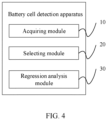
- FIG. 4 is a schematic structural diagram of a battery cell detection apparatus according to some embodiments of this application.
- the battery cell detection apparatus includes:
- a consistency detection result of the battery cells in the battery system is achieved by just selecting the reference battery cell from the battery cells and comparing the reference battery cell with the battery cells, without using cumulative capacity data, obtaining a variation in the state of charge values based on the cumulative capacity data and obtaining the consistency detection result of the battery cells based on the variation in the state of charge values. Even without the capacity data, a relative result can be obtained through calculation, thus consistency of the battery cells is calculated, and the accuracy of battery detection is improved.
Landscapes
- Physics & Mathematics (AREA)
- General Physics & Mathematics (AREA)
- Engineering & Computer Science (AREA)
- Manufacturing & Machinery (AREA)
- Chemical & Material Sciences (AREA)
- Chemical Kinetics & Catalysis (AREA)
- Electrochemistry (AREA)
- General Chemical & Material Sciences (AREA)
- Secondary Cells (AREA)
- Charge And Discharge Circuits For Batteries Or The Like (AREA)
Abstract
Description
- This application relates to the field of battery technologies, and specifically, to a battery detection method, apparatus, and device, and a storage medium.
- Generally, to implement consistency detection of battery packs, it is necessary to separately calculate the capacity/self-discharge of each battery cell. However, it is unable to record a significant amount of historical data in a BMS battery management system for capacity/self-discharge calculation. It is easier to implement the calculation in the cloud, but obtaining accurate cumulative capacity data in the cloud is often challenging, and more accurate consistency detection of battery packs cannot be implemented.
- In view of the foregoing problems, this application provides a battery detection method, apparatus, and device, and a storage medium, so as to address the issue that consistency detection cannot be performed for battery packs more accurately.
- According to a first aspect, this application provides a battery cell detection method including:
- acquiring state of charge values of each battery cell in a battery system at different time points within a preset time;
- selecting a reference battery cell from the battery cells; and
- performing multiple linear regression analysis based on state of charge values of the reference battery cell, the state of charge values of each battery cell, and timestamps at corresponding time points to obtain a consistency detection result of the battery cells in the battery system.
- In technical solutions of embodiments of this application, a consistency detection result of the battery cells in the battery system is achieved by just selecting a reference battery cell from the battery cells and comparing the reference battery cell with the battery cells, without using accurate cumulative capacity data, obtaining a variation in the state of charge values based on the cumulative capacity data and obtaining the consistency detection result of the battery cells based on the variation in the state of charge values. Even without the capacity data, a relative result can be obtained through calculation, thus consistency of the battery cells is calculated, and the accuracy of battery detection is improved.
- In some embodiments, the performing multiple linear regression analysis based on state of charge values of the reference battery cell, the state of charge values of each battery cell, and timestamps at corresponding time points to obtain a consistency detection result of the battery cells in the battery system includes:
- acquiring a first matrix established based on state of charge values of the reference battery cell, and acquiring a second matrix established based on the state of charge values of each battery cell and timestamps at corresponding time points;
- performing linear regression calculations based on the first matrix and the second matrix to obtain corresponding relative battery capacity and relative self-discharge of each battery cell; and
- obtaining a consistency detection result of the battery cells in the battery system based on the corresponding relative battery capacity and relative self-discharge of each battery cell.
- In the technical solution of these embodiments of this application, the corresponding relative battery capacity and relative self-discharge of each battery cell are obtained based on the state of charge values of the reference battery cell, the state of charge values of each battery cell, and the timestamps at the corresponding time points. In this way, the corresponding relative battery capacity and relative self-discharge of each battery cell are obtained using the characteristic that the battery cells in the battery system have the same discharge capacity, without using accurate cumulative capacity data, and thus the accuracy of battery detection is improved.
- In some embodiments, the performing linear regression calculations based on the first matrix and the second matrix to obtain corresponding relative battery capacity and relative self-discharge of each battery cell further includes:
- performing linear regression calculations based on the first matrix and the second matrix to obtain a regression result including a first regression coefficient and a second regression coefficient; and
- using the first regression coefficient as a corresponding relative battery capacity of each battery cell and using the second regression coefficient as a corresponding relative self-discharge of each battery cell based on the regression result.
- In the technical solution of these embodiments of this application, the corresponding relative battery capacity and relative self-discharge of each battery cell are obtained based on the statistically calculated positive correlation between the corresponding relative battery capacity and relative self-discharge of each battery cell and the state of charge values of the reference battery cell, the state of charge values of each battery cell, and the timestamps at the corresponding time points, without using accurate cumulative capacity data, and thus the efficiency of battery detection is improved.
- In some embodiments, the performing linear regression calculations based on the first matrix and the second matrix to obtain a regression result including a first regression coefficient and a second regression coefficient includes:
- establishing a linear regression model, where the linear regression model includes a correspondence between a first regression coefficient, a second regression coefficient, the state of charge values of the reference battery cell, the state of charge values of each battery cell, and the timestamps at the corresponding time points; and
- substituting the first matrix and the second matrix into the linear regression model for linear calculation to obtain the first regression coefficient and the second regression coefficient.
- In the technical solution of these embodiments of this application, the corresponding relative battery capacity and relative self-discharge of each battery cell, the state of charge values of the reference battery cell, the state of charge values of each battery cell, and the timestamps at the corresponding time points are used as known parameters for solving the linear regression model to obtain the regression coefficients. Compared with a conventional calculation method, the method of this application improves the accuracy of calculation.
- In some embodiments, the obtaining a positive correlation between the corresponding relative battery capacity and relative self-discharge of each battery cell and the state of charge values of the reference battery cell, the state of charge values of each battery cell, and the timestamps at the corresponding time points includes:
- acquiring a first relational expression reflecting a capacity variation of the reference battery cell and acquiring a second relational expression reflecting a capacity variation of each battery cell; and
- obtaining, based on the first relational expression and the second relational expression, a positive correlation between the corresponding relative battery capacity and relative self-discharge of each battery cell and the state of charge values of the reference battery cell, the state of charge values of each battery cell, and the timestamps at the corresponding time points.
- In the technical solution of these embodiments of this application, the positive correlation between the corresponding relative battery capacity and relative self-discharge of each battery cell and the state of charge values of the reference battery cell, the state of charge values of each battery cell, and the timestamps at the corresponding time points is obtained based on the first relational expression reflecting the capacity variation of the reference battery cell and the second relational expression reflecting the capacity variation of each battery cell, so that the relative battery capacity and relative self-discharge can be obtained more conveniently and simply based on the charge of state values of the reference battery cell, the charge of state of charge values of each battery cell, and the timestamps at the corresponding time points, thereby improving the efficiency of battery detection.
- In some embodiments, the obtaining, based on the first relational expression and the second relational expression, a positive correlation between the corresponding relative battery capacity and relative self-discharge of each battery cell and the state of charge values of the reference battery cell, the state of charge values of each battery cell, and the timestamps at the corresponding time points includes:
- performing parameter transformation on the first relational expression and the second relational expression under a condition that the first relational expression is equal to the second relational expression; and
- obtaining, based on a transformation result, a positive correlation between the corresponding relative battery capacity and relative self-discharge of each battery cell and the state of charge values of the reference battery cell, the state of charge values of each battery cell, and the timestamps at the corresponding time points.
- In the technical solution of these embodiments of this application, the positive correlation between the corresponding relative battery capacity and relative self-discharge of each battery cell and the state of charge values of the reference battery cell, the state of charge values of each battery cell, and the timestamps at the corresponding time points is obtained using the characteristic that the battery cells in the battery system have the same discharge capacity, so that more accurate relative battery capacity and relative self-discharge can be further obtained.
- In some embodiments, the acquiring a first relational expression reflecting a capacity variation of the reference battery cell and acquiring a second relational expression reflecting a capacity variation of each battery cell includes:
- obtaining, based on a battery capacity of the reference battery cell, a charge variation of the reference battery cell, self-discharge of the reference battery cell, and standing time of the reference battery cell, a first relational expression reflecting a capacity variation of the reference battery cell; and
- obtaining, based on the battery capacity of each battery cell, a charge variation of each battery cell, self-discharge of each battery cell, and standing time of each battery cell, a second relational expression reflecting a capacity variation of each battery cell.
- In the technical solution of these embodiments of this application, a parameter relationship between the corresponding relative battery capacity and relative self-discharge of each battery cell in the linear regression model is obtained based on the established first relational expression and second relational expression, and the relative battery capacity and relative self-discharge can be directly obtained according to the parameter relationship, so that battery detection is implemented based on the reference battery cell, and the accuracy of battery detection is improved.
- In some embodiments, the obtaining a consistency detection result of the battery cells in the battery system includes:
- obtaining, based on the corresponding relative battery capacity and relative self-discharge of each battery cell, a variation in the battery capacity of each battery cell and the battery capacity of the reference battery cell in the battery system; and
- obtaining a consistency detection result of the battery cells in the battery system based on the variation.
- In the technical solution of these embodiments of this application, consistency detection of the battery is implemented based on the variation in the battery capacity of each battery cell and the battery capacity of the reference battery cell, and the accuracy of battery detection is improved.
- In some embodiments, the obtaining, based on the corresponding relative battery capacity and relative self-discharge of each battery cell, a variation in the battery capacity of each battery cell and the battery capacity of the reference battery cell in the battery system includes:
- substituting the corresponding relative battery capacity and relative self-discharge of each battery cell with the regression result to obtain a correspondence between the first matrix and the second matrix;
- obtaining, based on the correspondence between the first matrix and the second matrix, a target correspondence between the state of charge values of the battery cells and the state of charge values of the reference battery cell in the battery system; and
- obtaining, based on the target correspondence, a variation in the battery capacity of each battery cell and the battery capacity of the reference battery cell in the battery system.
- In the technical solution of these embodiments of this application, the state of charge values of the battery cells and the state of charge values of the reference battery cell in the battery system are retrodicted in the regression result based on the corresponding relative battery capacity and relative self-discharge of each battery cell, so that the variation in the battery capacity of each battery cell and the battery capacity of the reference battery cell is obtained, thereby implementing consistency detection of the battery and improving the accuracy of battery detection.
- In some embodiments, the obtaining, based on the target correspondence, a variation in the battery capacity of each battery cell and the battery capacity of the reference battery cell in the battery system includes:
- under a condition that the state of charge values of each battery cell in the battery system are first state of charge values, obtaining corresponding first reference state of charge values of the reference battery cell based on the target correspondence;
- under a condition that the state of charge values of each battery cell in the battery system are second state of charge values, obtaining corresponding second reference state of charge values of the reference battery cell based on the correspondence, where the second state of charge value is less than the first state of charge value; and
- using a difference value between the first reference state of charge value and the second reference state of charge value as a variation in the battery capacity of each battery cell and the battery capacity of the reference battery cell.
- In the technical solution of these embodiments of this application, the variation in the battery capacity of each battery cell and the battery capacity of the reference battery cell is obtained based on the correspondence between the state of charge values of each battery cell and the state of charge values of the reference battery cell, so that consistency detection of the battery is implemented and the accuracy of battery detection is improved.
- In some embodiments, the battery detection method further includes:
providing a warning under a condition that the corresponding relative battery capacity, relative self-discharge, and variation of each battery cell satisfy a preset warning condition. - In the technical solution of these embodiments of this application, under a condition that the preset warning condition is satisfied, warning is performed, so that the use safety of the battery is improved.
- In some embodiments, the preset warning condition includes at least one of the following:
- the corresponding relative battery capacity of each battery cell is less than a relative battery capacity threshold;
- a capacity decrease speed of the corresponding relative battery capacity of each battery cell is greater than a decrease speed threshold within a relative battery capacity monitoring time;
- the corresponding relative self-discharge of each battery cell is greater than a relative self-discharge threshold;
- a self-discharge increase speed of the corresponding relative self-discharge of each battery cell is greater than an increase speed threshold within a relative self-discharge monitoring time; and
- the variation in the battery capacity of each battery cell and the battery capacity of the reference battery cell in the battery system is greater than a variation threshold.
- In the technical solution of these embodiments of this application, under a condition that the preset warning condition is satisfied, a warning is provided based on threshold comparison from multiple perspectives, so that effectiveness of battery detection is improved.
- According to a second aspect, this application provides a battery cell detection apparatus, where the battery cell detection apparatus includes:
- an acquiring module, configured to acquire state of charge values of each battery cell in a battery system at different time points within a preset time;
- a selecting module, configured to select a reference battery cell from the battery cells; and
- a regression analysis module, configured to perform multiple linear regression analysis based on state of charge values of the reference battery cell, the state of charge values of each battery cell, and timestamps at corresponding time points to obtain a consistency detection result of the battery cells in the battery system.
- In technical solutions of embodiments of this application, a consistency detection result of the battery cells in the battery system is achieved by just selecting a reference battery cell from the battery cells and comparing the reference battery cell with the battery cells, without using accurate cumulative capacity data, obtaining a variation in the state of charge values based on the cumulative capacity data and obtaining the consistency detection result of the battery cells based on the variation in the state of charge values. Even without the capacity data, a relative result can be obtained through calculation, thus consistency of the battery cells is calculated, and the accuracy of battery detection is improved.
- According to a third aspect, this application provides a battery cell detection device. The battery cell detection device includes a memory, a processor, and a battery detection program stored in the memory and capable of running on the processor, where the battery detection program is configured to implement the battery detection method as described above.
- According to a fourth aspect, this application provides a storage medium, where a battery detection program is stored in the storage medium, and when the battery detection program is executed by a processor, the battery detection method as described above is implemented.
- The foregoing descriptions are merely an overview of the technical solution of this application. For a better understanding of the technical means in this application such that they can be implemented according to the content of the specification, and to make the above and other objectives, features and advantages of this application more obvious and easier to understand, the following describes specific embodiments of this application.
-
-
FIG. 1 is a flowchart of a battery cell detection method according to some embodiments of this application; -
FIG. 2 is a flowchart of a battery cell detection method according to some other embodiments of this application; -
FIG. 3 is an overall schematic flowchart of a battery cell detection method according to some embodiments of this application; and -
FIG. 4 is a schematic structural diagram of a battery cell detection apparatus according to some embodiments of this application. - The following describes in detail the embodiments of technical solutions of this application with reference to the accompanying drawings. The following embodiments are merely intended for a clearer description of the technical solutions of this application and therefore are merely used as examples which do not constitute any limitation on the protection scope of this application.
- Unless otherwise defined, all technical and scientific terms used herein shall have the same meanings as commonly understood by persons skilled in the art to which this application pertains. The terms used herein are intended to merely describe the specific embodiments rather than to limit this application. The terms "include", "comprise", and any other variations thereof in the specification, claims and brief description of drawings of this application are intended to cover non-exclusive inclusions.
- In the descriptions of the embodiments of this application, the technical terms "first", "second", and the like are merely intended to distinguish between different objects, and shall not be understood as any indication or implication of relative importance or any implicit indication of the number, specific sequence, or primary-secondary relationship of the technical features indicated. In the descriptions of the embodiments of this application, "multiple" means more than two, unless otherwise specifically defined.
- In this specification, reference to "embodiment" means that specific features, structures or characteristics described with reference to the embodiment may be incorporated in at least one embodiment of this application. The word "embodiment" appearing in various places in the specification does not necessarily refer to the same embodiment or an independent or alternative embodiment that is exclusive of other embodiments. It is explicitly or implicitly understood by persons skilled in the art the embodiments described herein may be combined with other embodiments.
- In the description of the embodiments of this application, the term "and/or" is only an associative relationship for describing associated objects, indicating that three relationships may be present. For example, A and/or B may indicate the following three cases: presence of only A, presence of both A and B, and presence of only B. In addition, the character "/" in this specification generally indicates an "or" relationship between the contextually associated objects.
- In the descriptions of the embodiments of this application, the term "multiple" means more than two (inclusive). Similarly, "multiple groups" means more than two (inclusive) groups, and "multiple pieces" means more than two (inclusive) pieces.
- In the description of the embodiments of this application, the orientations or positional relationships indicated by the technical terms "center", "longitudinal", "transverse", "length", "width", "thickness", "upper", "lower", "front", "rear", "left", "right", "vertical", "horizontal", "top", "bottom", "inside", "outside", "clockwise", "counterclockwise", "axial", " radial", "circumferential", and the like are based on the orientations or positional relationships as shown in the accompanying drawings. These terms are merely for ease and brevity of description of the embodiments of this application rather than indicating or implying that the means or components mentioned must have specific orientations or must be constructed or manipulated according to specific orientations, and therefore shall not be construed as any limitation on the embodiments of this application.
- In the description of the embodiments of this application, unless otherwise specified and defined explicitly, the terms "mounting", "connection", "join", and "fastening" should be understood in their general senses. For example, they may refer to a fixed connection, a detachable connection, or an integral connection, may refer to a mechanical connection or electrical connection, and may refer to a direct connection, an indirect connection via an intermediate medium, an internal communication between two elements, or an interaction between two elements. Persons of ordinary skill in the art can understand specific meanings of these terms in the embodiments of this application as appropriate to specific situations. The specific embodiments described herein are merely intended to explain the present invention rather than limit the present invention.
- Generally, to implement consistency detection of battery packs, it is necessary to separately calculate the capacity/self-discharge of each battery cell. However, it is unable to record a significant amount of historical data in a BMS battery management system for capacity/self-discharge calculation. It is easier to implement the calculation in cloud, but obtaining accurate cumulative capacity data in cloud is often challenging. Therefore, more accurate consistency detection of battery packs cannot be performed.
- To resolve the existing problem that more accurate consistency detection of battery packs cannot be performed, in the embodiments of this application, a consistency detection result of the battery cells in the battery system is achieved by just selecting a reference battery cell from the battery cells and comparing the reference battery cell with the battery cells, without using accurate cumulative capacity data, obtaining a variation in the state of charge values based on the cumulative capacity data and obtaining the consistency detection result of the battery cells based on the variation in the state of charge values. Even without the capacity data, a relative result can be obtained through calculation, thus consistency of the battery cells is calculated, and the accuracy of battery detection is improved.
- The battery cell disclosed in the embodiments of this application may be used for electric apparatuses that use a battery as a power source or various energy storage systems that use a battery as an energy storage element. The electric apparatus may be but is not limited to a mobile phone, a tablet computer, a laptop computer, an electric toy, an electric tool, an electric bicycle, an electric vehicle, a ship, and a spacecraft. The electric toy may be a fixed or mobile electric toy, for example, a game console, an electric toy car, an electric toy ship, and an electric toy airplane. The spacecraft may include an airplane, a rocket, a space shuttle, a spaceship, and the like.
- To resolve the existing problem that more accurate consistency detection of battery packs cannot be performed, this application proposes a battery detection method. Referring to
FIG. 1 , in the example, the battery detection method includes the following steps. - Step S10. Acquire state of charge values of each battery cell in a battery system at different time points within a preset time.
- It should be noted that this embodiment may be executed by a controller in the battery system or another service processor, and this is not limited in this embodiment. In this embodiment, the controller in the battery system is used as an example for description, where the preset time may be 1 day or 1 hour, and this is not limited in this embodiment. In an example in which the preset time is 1 day, the state of charge values of each battery cell in the battery system at different time points within the preset time are acquired, that is, SOC values, to provide data support for subsequent linear calculation. Generally, state of charge values are usually obtained through calculation based on an open circuit voltage of a battery after standing.
- In a specific implementation, a sensor is used to acquire data such as current, voltage, and temperature of the battery. The sensor is connected to the controller in the battery system and transmits the acquired data such as current, voltage, and temperature of the battery to the controller in the battery system. After obtaining the data such as current, voltage, and temperature of the battery, the controller screens the data such as current, voltage, and temperature of the battery to obtain data satisfying a condition of the open circuit voltage, that is, open circuit voltage data of the battery after a certain time of full standing. In this way, the detection accuracy is improved. The controller in the battery system obtains state of charge values at different time points based on the open circuit voltage of the battery after standing that is acquired by the sensor, thereby implementing automatic data acquisition.
- Step S20. Select a reference battery cell from the battery cells.
- In this embodiment, the reference battery cell may be one battery cell selected from the battery cells in the battery system. The reference battery cell may be selected randomly or selected in a default manner. Alternatively, an average value of the battery may be used as a virtual reference battery. This is not limited in this embodiment. One reference battery cell is selected using the characteristic that the battery cells in the battery system have the same discharge capacity, a battery capacity variation ΔAh of the reference battery cell is used to replace ΔAh of all the other battery cells, so that consistency detection of the battery can be implemented without capacity information, avoiding errors in detection results caused by miscalculation of the capacity information, thereby improving the accuracy of battery detection.
- Step S30. Perform multiple linear regression analysis based on state of charge values of the reference battery cell, the state of charge values of each battery cell, and timestamps at corresponding time points to obtain a consistency detection result of the battery cells in the battery system.
- It should be noted that the state of charge values of the reference battery cell are represented by SOCref , the state of charge values of each battery cell are represented by SOCn , and the timestamps at corresponding time points is represented by Time, where SOCref , SOCn , and Time are used for multiple linear regression analysis, and consistency detection of the battery cells in the battery system can be implemented without ΔAh and state of charge value variation ΔSOC.
- Generally, battery capacity, self-discharge, and state of equilibrium are important characteristic parameters of battery packs. The consistency of a battery system is measured based on the battery capacity, self-discharge, and state of equilibrium. In consistency detection of battery cells, capacity differences of the battery cells in the battery system are detected. In this embodiment, consistency detection of the battery cells is implemented using the reference battery cell. Therefore, multiple linear regression analysis is performed based on the state of charge values of the reference battery cell, the state of charge values of each battery cell, and timestamps at corresponding time points to obtain the relative battery capacity and relative self-discharge of each battery cell, and consistency detection of the battery cells is implemented based on the relative battery capacity and relative self-discharge of each battery cell, so that the original consistency detection manner of the battery is changed, and the consistency detection of the battery is performed in a totally new manner. In this way, the consistency detection of the battery can be implemented without capacity information, avoiding errors in detection results caused by miscalculation of the capacity information, thereby improving the accuracy of battery detection.
- In technical solutions of embodiments of this application, a consistency detection result of the battery cells in the battery system is achieved by just selecting a reference battery cell from the battery cells and comparing the reference battery cell with the battery cells, without using accurate cumulative capacity data, obtaining a variation in the state of charge values based on the cumulative capacity data and obtaining the consistency detection result of the battery cells based on the variation in the state of charge values. Even without the capacity data, a relative result can be obtained through calculation, thus consistency of the battery cells is calculated, and the accuracy of battery detection is improved.
- A second embodiment of the present invention is proposed based on the first embodiment. In the second embodiment, as shown in
FIG. 2 , step S30 includes the following steps. - Step S301. Acquire a first matrix established based on state of charge values of the reference battery cell, and acquire a second matrix established based on the state of charge values of each battery cell and timestamps at corresponding time points.
- Step S302. Perform linear regression calculations based on the first matrix and the second matrix to obtain corresponding relative battery capacity and relative self-discharge of each battery cell.
- Step S303. Obtain a consistency detection result of the battery cells in the battery system based on the corresponding relative battery capacity and relative self-discharge of each battery cell.
- It should be noted that the first matrix Y established based on the state of charge values of the reference battery cell is:

- The second matrix X established based on the state of charge values of each battery cell and timestamps at corresponding time points is:

- In a specific implementation, data at different time points within a certain time window, including time and the selected reference battery cell, are collected to obtain X and Y that are inputted into matrices (for example, there are t pieces of data), and linear regression calculations are performed based on the first matrix and the second matrix to obtain corresponding relative battery capacity and relative self-discharge of each battery cell.
- Linear regression calculations are performed to obtain a result:

- Relative capacity:

- relative self-discharge:

- where CAPn represents the capacity of each battery cell, CAPref represents the capacity of the reference battery cell,

- In this embodiment, the corresponding relative battery capacity and relative self-discharge of each battery cell are obtained based on the state of charge values of the reference battery cell, the state of charge values of each battery cell, and the timestamps at the corresponding time points. In this way, the corresponding relative battery capacity and relative self-discharge of each battery cell are obtained using the characteristic that the battery cells in the battery system have the same discharge capacity, without using accurate cumulative capacity data, and thus the accuracy of battery detection is improved.
- According to some embodiments of this application, optionally, step S302 includes:
- performing linear regression calculations based on the first matrix and the second matrix to obtain a regression result including a first regression coefficient and a second regression coefficient; and
- using the first regression coefficient as a corresponding relative battery capacity of each battery cell and using the second regression coefficient as a corresponding relative self-discharge of each battery cell based on the regression result.
- It should be noted that the first regression coefficient is β2, and the second regression coefficient is β3. In an established linear relationship between the first matrix and the second matrix, known input parameters are SOCreft , SOCnt , and Timet , and a linear model related to SOCreft , SOCnt , and Timet is obtained based on linear calculation.
- Under a condition that a positive correlation between the corresponding relative battery capacity and relative self-discharge of each battery cell and the state of charge values of the reference battery cell, the state of charge values of each battery cell, and the timestamps at the corresponding time points is statistically calculated, the correlation thereof is:

- A relationship between


- It can be seen that the following can be obtained:


- In the technical solution of these embodiments of this application, the corresponding relative battery capacity and relative self-discharge of each battery cell are obtained based on the statistically calculated positive correlation between the corresponding relative battery capacity and relative self-discharge of each battery cell and the state of charge values of the reference battery cell, the state of charge values of each battery cell, and the timestamps at the corresponding time points, without using accurate cumulative capacity data, and thus the efficiency of battery detection is improved.
- According to some embodiments of this application, optionally, the performing linear regression calculations based on the first matrix and the second matrix to obtain a regression result including a first regression coefficient and a second regression coefficient includes:
- establishing a linear regression model, where the linear regression model includes a correspondence between a first regression coefficient, a second regression coefficient, the state of charge values of the reference battery cell, the state of charge values of each battery cell, and the timestamps at the corresponding time points; and
- substituting the first matrix and the second matrix into the linear regression model for linear calculation to obtain the first regression coefficient and the second regression coefficient.
- In these embodiments, the linear regression model is denoted as Formula 1, and Formula 1 can be solved to obtain the first regression coefficient and the second regression coefficient, so as to obtain the corresponding relative battery capacity and relative self-discharge of each battery cell, without using accurate cumulative capacity data. In this way, the calculation accuracy is improved.
- According to some embodiments of this application, optionally, the obtaining a positive correlation between the corresponding relative battery capacity and relative self-discharge of each battery cell and the state of charge values of the reference battery cell, the state of charge values of each battery cell, and the timestamps at the corresponding time points includes:
- acquiring a first relational expression reflecting a capacity variation of the reference battery cell and acquiring a second relational expression reflecting a capacity variation of each battery cell; and
- obtaining, based on the first relational expression and the second relational expression, a positive correlation between the corresponding relative battery capacity and relative self-discharge of each battery cell and the state of charge values of the reference battery cell, the state of charge values of each battery cell, and the timestamps at the corresponding time points.
- The first relational expression is:

- The second relational expression is:

- In these embodiments, the positive correlation between the corresponding relative battery capacity and relative self-discharge of each battery cell and the state of charge values of the reference battery cell, the state of charge values of each battery cell, and the timestamps at the corresponding time points is obtained based on the first relational expression reflecting the capacity variation of the reference battery cell and the second relational expression reflecting the capacity variation of each battery cell, so that the relative battery capacity and relative self-discharge can be obtained more conveniently and simply based on the charge of state values of the reference battery cell, the charge of state of charge values of each battery cell, and the timestamps at the corresponding time points, thereby improving the efficiency of battery detection.
- According to some embodiments of this application, optionally, the obtaining, based on the first relational expression and the second relational expression, a positive correlation between the corresponding relative battery capacity and relative self-discharge of each battery cell and the state of charge values of the reference battery cell, the state of charge values of each battery cell, and the timestamps at the corresponding time points includes:
- performing parameter transformation on the first relational expression and the second relational expression under a condition that the first relational expression is equal to the second relational expression; and
- obtaining, based on a transformation result, a positive correlation between the corresponding relative battery capacity and relative self-discharge of each battery cell and the state of charge values of the reference battery cell, the state of charge values of each battery cell, and the timestamps at the corresponding time points.
- In a specific implementation, the battery cells in the battery system have the same discharge capacity. Therefore, the first relational expression is equal to the second relational expression. To be specific, the following is obtained based on Formula 3 and Formula 4:

- The following is obtained through transformation:

- In this way, a positive correlation between SOCreft , SOCnt , Timet ,


- In this application, the positive correlation between the corresponding relative battery capacity and relative self-discharge of each battery cell and the state of charge values of the reference battery cell, the state of charge values of each battery cell, and the timestamps at the corresponding time points is obtained using the characteristic that the battery cells in the battery system have the same discharge capacity, so that more accurate relative battery capacity and relative self-discharge can be further obtained.
- According to some embodiments of this application, optionally, the acquiring a first relational expression reflecting a capacity variation of the reference battery cell and acquiring a second relational expression reflecting a capacity variation of each battery cell includes:
- obtaining, based on a battery capacity of the reference battery cell, a charge variation of the reference battery cell, self-discharge of the reference battery cell, and standing time of the reference battery cell, a first relational expression reflecting a capacity variation of the reference battery cell; and
- obtaining, based on the battery capacity of each battery cell, a charge variation of each battery cell, self-discharge of each battery cell, and standing time of each battery cell, a second relational expression reflecting a capacity variation of each battery cell.
- The first relational expression is:

- The second relational expression is:

- In these embodiments, a parameter relationship between the corresponding relative battery capacity and relative self-discharge of each battery cell in the linear regression model is obtained based on the established first relational expression and second relational expression, and the relative battery capacity and relative self-discharge can be directly obtained according to the parameter relationship, so that battery detection is implemented based on the reference battery cell, and the accuracy of battery detection is improved.
- According to some embodiments of this application, optionally, the obtaining a consistency detection result of the battery cells in the battery system includes:
- obtaining, based on the corresponding relative battery capacity and relative self-discharge of each battery cell, a variation in the battery capacity of each battery cell and the battery capacity of the reference battery cell in the battery system; and
- obtaining a consistency detection result of the battery cells in the battery system based on the variation.
- In these embodiments, the variation in the battery capacity of each battery cell and the battery capacity of the reference battery cell in the battery system is a difference value between the battery capacity of each battery cell and the battery capacity of the reference battery cell in the battery system. Based on the difference value between the battery capacity of each battery cell and the battery capacity of the reference battery cell, capacity differences between the battery cells can be obtained, and thus a consistency detection result of the battery cells in the battery system can be obtained.
- According to some embodiments of this application, optionally, the obtaining, based on the corresponding relative battery capacity and relative self-discharge of each battery cell, a variation in the battery capacity of each battery cell and the battery capacity of the reference battery cell in the battery system includes:
substituting a regression result corresponding to the corresponding relative battery capacity and relative self-discharge of each battery cell into a third relational expression to obtain a correspondence between the state of charge values of each battery cell and the state of charge values of the reference battery cell; and obtaining, based on the correspondence, a variation in the battery capacity of each battery cell and the battery capacity of the reference battery cell in the battery system. - The calculated regression result of each battery cell is substituted into Formula 6 to obtain a correspondence between state of charge of each battery and state of charge of the reference battery. A correspondence between the state of charge of each battery and the state of charge of the reference battery in a fully charged state and a fully discharged state respectively, and an available state of charge range in the battery system is calculated based on the correspondence, where a third relational expression is shown in Formula 6.

- The variation in the battery capacity of each battery cell and the battery capacity of the reference battery cell can be obtained based on the target correspondence, and a relative relationship between the capacity of the battery system and the capacity of the reference battery is further obtained, thereby implementing detection of the state of equilibrium.
- In this application, the state of charge values of the battery cells and the state of charge values of the reference battery cell in the battery system are retrodicted in the regression result based on the corresponding relative battery capacity and relative self-discharge of each battery cell, so that the variation in the battery capacity of each battery cell and the battery capacity of the reference battery cell is obtained, and the relative relationship between the capacity of the battery system and the capacity of the reference battery is further obtained, thereby implementing consistency detection of the battery and improving the accuracy of battery detection.
- According to some embodiments of this application, optionally, the obtaining, based on the target correspondence, a variation in the battery capacity of each battery cell and the battery capacity of the reference battery cell in the battery system includes:
under a condition that the state of charge values of each battery cell in the battery system are first state of charge values, obtaining corresponding first reference state of charge values of the reference battery cell based on the target correspondence; under a condition that the state of charge values of each battery cell in the battery system are second state of charge values, obtaining corresponding second reference state of charge values of the reference battery cell based on the correspondence, where the second state of charge value is less than the first state of charge value; and using a difference value between the first reference state of charge value and the second reference state of charge value as a variation in the battery capacity of each battery cell and the battery capacity of the reference battery cell. - In these embodiments, in calculation of the state of equilibrium, for example, m battery cells are provided in the battery system, a relative relationship between an available capacity of the battery system and the capacity of the reference battery cell within a range of 0 to 100% is calculated; at the current time point Timenow, the first state of charge value is a state of charge value SOC ref_n_100% == [1 100% Timenow]•β of the reference battery cell when SOCn is 100%, obtained according to Formula 6 under a condition that the state of charge value of each battery cell is 100%, that is, 100%SOC, SOCn is 100%, and the corresponding relative battery capacity and relative self-discharge of each battery cell is β; a minimum value of the state of charge values of all the battery cells in the system is SOCref_hi = min(SOC ref_1_100%, Soc ref_2_100% ...Soc ref _m_100%) ; and the first reference state of charge value is obtained as SOCref_hi.
- Similarly, the second state of charge value is a state of charge value SOC ref_n_0% == [1 0 Timenow]•β of the reference battery cell when SOCn is 0, obtained according to Formula 6 under a condition that the state of charge value of each battery cell is 0, that is, 0SOC, SOCn is 0SOC, and the corresponding relative battery capacity and relative self-discharge of each battery cell is β; a maximum value of the state of charge values of all the battery cells in the system is SOCref_lo = max(SOC ref_1_0%, SOC ref_2_0% ...SOC ref_m_0%); and the second reference state of charge value is obtained as SOCref_lo.
- Therefore, the available capacity of the battery system decreases with respect to the capacity of the reference battery cell: 100% - SOCref_hi + SOCref_lo , so that the variation in the available capacity of the battery system and the battery capacity of the reference battery cell is obtained.
- In this application, the variation in the battery capacity of each battery cell and the battery capacity of the reference battery cell is obtained based on the correspondence between the state of charge values of each battery cell and the state of charge values of the reference battery cell, thereby implementing consistency detection of the battery and improving the accuracy of battery detection.
- According to some embodiments of this application, optionally, the battery detection method further includes:
providing a warning under a condition that the corresponding relative battery capacity, relative self-discharge, and variation of each battery cell satisfy a preset warning condition. - As shown in the overall schematic flowchart in
FIG. 3 , the following steps are mainly included. - Step 1. Read data such as current, voltage, and temperature of the battery, excluding capacity data.
- Step 2. Filter the data satisfying an OCV condition, and consider that the battery satisfies the OCV condition after it undergoes a certain time of full standing.
- Step 3. Select multiple pieces of OCV data within a certain time window for regression calculation.
- Step 4. Obtain a consistency result of the battery.
- Step 5. Provide a capacity consistency warning for a battery whose relative capacity is low or relative capacity decrease speed is too high; provide a self-discharge consistency warning for a battery whose relative self-discharge is high or relative self-discharge increase speed is too high; and calculate the capacity of the battery system based on the capacity of the battery cell.
- According to some embodiments of this application, optionally, the preset warning condition includes at least one of the following:
- the corresponding relative battery capacity of each battery cell is less than a relative battery capacity threshold;
- a capacity decrease speed of the corresponding relative battery capacity of each battery cell is greater than a decrease speed threshold within a relative battery capacity monitoring time;
- the corresponding relative self-discharge of each battery cell is greater than a relative self-discharge threshold;
- a self-discharge increase speed of the corresponding relative self-discharge of each battery cell is greater than an increase speed threshold within a relative self-discharge monitoring time; and
- the variation in the battery capacity of each battery cell and the battery capacity of the reference battery cell in the battery system is greater than a variation threshold.
- In this application, under a condition that the preset warning condition is satisfied, a warning is provided based on threshold comparison from multiple perspectives, so that effectiveness of battery detection is improved.
- According to some embodiments of this application, referring to
FIG. 4, FIG. 4 is a schematic structural diagram of a battery cell detection apparatus according to some embodiments of this application. - In these embodiments, the battery cell detection apparatus includes:
- an acquiring
module 10, configured to acquire state of charge values of each battery cell in a battery system at different time points within a preset time; - a selecting
module 20, configured to select a reference battery cell from the battery cells; and - a
regression analysis module 30, configured to perform multiple linear regression analysis based on state of charge values of the reference battery cell, the state of charge values of each battery cell, and timestamps at corresponding time points to obtain a consistency detection result of the battery cells in the battery system. - In this application, a consistency detection result of the battery cells in the battery system is achieved by just selecting the reference battery cell from the battery cells and comparing the reference battery cell with the battery cells, without using cumulative capacity data, obtaining a variation in the state of charge values based on the cumulative capacity data and obtaining the consistency detection result of the battery cells based on the variation in the state of charge values. Even without the capacity data, a relative result can be obtained through calculation, thus consistency of the battery cells is calculated, and the accuracy of battery detection is improved.
- In conclusion, it should be noted that the foregoing embodiments are merely for describing the technical solutions of this application rather than for limiting this application. Although this application has been described in detail with reference to the foregoing embodiments, persons of ordinary skill in the art should appreciate that they can still make modifications to the technical solutions described in the embodiments or make equivalent replacements to some or all technical features thereof without departing from the scope of the technical solutions of the embodiments of this application. All such modifications and equivalent replacements shall fall within the scope of claims and specification of this application. In particular, as long as there is no structural conflict, the various technical features mentioned in the embodiments can be combined in any manner. This application is not limited to the specific embodiments disclosed in this specification, but includes all technical solutions falling within the scope of the claims.
Claims (15)
- A battery detection method, characterized in that the battery detection method comprises:Acquiring (S10) state of charge values of each battery cell in a battery system at different time points within a preset time;selecting (S20) a reference battery cell from the battery cells; andperforming multiple linear regression analysis (S30) based on state of charge values of the reference battery cell, the state of charge values of each battery cell, and timestamps at corresponding time points to obtain a consistency detection result of the battery cells in the battery system.
- The battery detection method according to claim 1, characterized in that the performing multiple linear regression analysis (S30) based on state of charge values of the reference battery cell, the state of charge values of each battery cell, and timestamps at corresponding time points to obtain a consistency detection result of the battery cells in the battery system comprises:acquiring (S301) a first matrix established based on state of charge values of the reference battery cell, and acquiring a second matrix established based on the state of charge values of each battery cell and timestamps at corresponding time points;performing linear regression calculations (S302) based on the first matrix and the second matrix to obtain corresponding relative battery capacity and relative self-discharge of each battery cell; andobtaining (S303) a consistency detection result of the battery cells in the battery system based on the corresponding relative battery capacity and relative self-discharge of each battery cell.
- The battery detection method according to claim 2, characterized in that the performing linear regression calculations (S302) based on the first matrix and the second matrix to obtain corresponding relative battery capacity and relative self-discharge of each battery cell comprises:performing linear regression calculations based on the first matrix and the second matrix to obtain a regression result including a first regression coefficient and a second regression coefficient; andusing the first regression coefficient as a corresponding relative battery capacity of each battery cell and using the second regression coefficient as a corresponding relative self-discharge of each battery cell based on the regression result.
- The battery detection method according to claim 3, characterized in that the performing linear regression calculations based on the first matrix and the second matrix to obtain a regression result comprising a first regression coefficient and a second regression coefficient comprises:establishing a linear regression model, where the linear regression model includes a correspondence between a first regression coefficient, a second regression coefficient, the state of charge values of the reference battery cell, the state of charge values of each battery cell, and the timestamps at the corresponding time points; andsubstituting the first matrix and the second matrix into the linear regression model for linear calculation to obtain the first regression coefficient and the second regression coefficient.
- The battery detection method according to any one of claims 1 to 4, characterized in that the battery detection method further comprises:acquiring a first relational expression reflecting a capacity variation of the reference battery cell and acquiring a second relational expression reflecting a capacity variation of each battery cell; andobtaining, based on the first relational expression and the second relational expression, a positive correlation between the corresponding relative battery capacity and relative self-discharge of each battery cell and the state of charge values of the reference battery cell, the state of charge values of each battery cell, and the timestamps at the corresponding time points.
- The battery detection method according to claim 5, characterized in that the obtaining, based on the first relational expression and the second relational expression, a positive correlation between the corresponding relative battery capacity and relative self-discharge of each battery cell and the state of charge values of the reference battery cell, the state of charge values of each battery cell, and the timestamps at the corresponding time points comprises:performing parameter transformation on the first relational expression and the second relational expression under a condition that the first relational expression is equal to the second relational expression; andobtaining, based on a transformation result, a positive correlation between the corresponding relative battery capacity and relative self-discharge of each battery cell and the state of charge values of the reference battery cell, the state of charge values of each battery cell, and the timestamps at the corresponding time points.
- The battery detection method according to claim 5, characterized in that the acquiring a first relational expression reflecting a capacity variation of the reference battery cell and acquiring a second relational expression reflecting a capacity variation of each battery cell comprises:obtaining, based on a battery capacity of the reference battery cell, a charge variation of the reference battery cell, self-discharge of the reference battery cell, and timestamps at corresponding time points of the reference battery cell, a first relational expression reflecting a capacity variation of the reference battery cell; andobtaining, based on the battery capacity of each battery cell, a charge variation of each battery cell, self-discharge of each battery cell, and standing time of each battery cell, a second relational expression reflecting a capacity variation of each battery cell.
- The battery detection method according to claim 3, characterized in that the obtaining a consistency detection result of the battery cells in the battery system comprises:obtaining, based on the corresponding relative battery capacity and relative self-discharge of each battery cell, a variation in the battery capacity of each battery cell and the battery capacity of the reference battery cell in the battery system; andobtaining a consistency detection result of the battery cells in the battery system based on the variation.
- The battery detection method according to claim 8, characterized in that the obtaining, based on the corresponding relative battery capacity and relative self-discharge of each battery cell, a variation in the battery capacity of each battery cell and the battery capacity of the reference battery cell in the battery system comprises:substituting a regression result corresponding to the corresponding relative battery capacity and relative self-discharge of each battery cell into a third relational expression to obtain a correspondence between the state of charge values of each battery cell and the state of charge values of the reference battery cell; andobtaining, based on the correspondence, a variation in the battery capacity of each battery cell and the battery capacity of the reference battery cell in the battery system.
- The battery detection method according to claim 9, characterized in that the obtaining, based on the correspondence, a variation in the battery capacity of each battery cell and the battery capacity of the reference battery cell in the battery system comprises:under a condition that the state of charge values of each battery cell in the battery system are first state of charge values, obtaining corresponding first reference state of charge values of the reference battery cell based on the correspondence;under a condition that the state of charge values of each battery cell in the battery system are second state of charge values, obtaining corresponding second reference state of charge values of the reference battery cell based on the correspondence, wherein the second state of charge value is less than the first state of charge value; andusing a difference value between the first reference state of charge value and the second reference state of charge value as a variation in the battery capacity of each battery cell and the battery capacity of the reference battery cell.
- The battery detection method according to claim 8, characterized in that the battery detection method further comprises:
providing a warning under a condition that the corresponding relative battery capacity, relative self-discharge, and variation of each battery cell satisfy a preset warning condition. - The battery detection method according to claim 11, characterized in that the preset warning condition comprises at least one of the following:the corresponding relative battery capacity of each battery cell is less than a relative battery capacity threshold;a capacity decrease speed of the corresponding relative battery capacity of each battery cell is greater than a decrease speed threshold within a relative battery capacity monitoring time;the corresponding relative self-discharge of each battery cell is greater than a relative self-discharge threshold;a self-discharge increase speed of the corresponding relative self-discharge of each battery cell is greater than an increase speed threshold within a relative self-discharge monitoring time; andthe variation in the battery capacity of each battery cell and the battery capacity of the reference battery cell in the battery system is greater than a variation threshold.
- A battery detection apparatus, characterized in that the battery detection apparatus comprises:an acquiring module (10), configured to acquire state of charge values of each battery cell in a battery system at different time points within a preset time;a selecting module (20), configured to select a reference battery cell from the battery cells; anda regression analysis module (30), configured to perform multiple linear regression analysis based on state of charge values of the reference battery cell, the state of charge values of each battery cell, and timestamps at corresponding time points to obtain a consistency detection result of the battery cells in the battery system.
- A battery detection device, characterized in that the battery detection device comprises a memory, a processor, and a battery detection program stored in the memory and capable of running on the processor, wherein the battery detection program is configured to implement the battery detection method according to any one of claims 1 to 12.
- A storage medium, characterized in that the storage medium stores a battery detection program, wherein when the battery detection program is executed by a processor, the battery detection method according to any one of claims 1 to 12 is implemented.
Applications Claiming Priority (1)
| Application Number | Priority Date | Filing Date | Title |
|---|---|---|---|
| CN202310786385.8A CN119270117A (en) | 2023-06-29 | 2023-06-29 | Battery detection method, device, equipment and storage medium |
Publications (2)
| Publication Number | Publication Date |
|---|---|
| EP4484979A1 true EP4484979A1 (en) | 2025-01-01 |
| EP4484979B1 EP4484979B1 (en) | 2025-12-31 |
Family
ID=92258903
Family Applications (1)
| Application Number | Title | Priority Date | Filing Date |
|---|---|---|---|
| EP24185024.7A Active EP4484979B1 (en) | 2023-06-29 | 2024-06-27 | METHOD, DEVICE, APPARATUS AND STORAGE MEDIUM FOR BATTERY DETECTION |
Country Status (3)
| Country | Link |
|---|---|
| US (1) | US20250004066A1 (en) |
| EP (1) | EP4484979B1 (en) |
| CN (1) | CN119270117A (en) |
Families Citing this family (1)
| Publication number | Priority date | Publication date | Assignee | Title |
|---|---|---|---|---|
| CN119395578B (en) * | 2025-01-02 | 2025-04-01 | 中汽研新能源汽车检验中心(天津)有限公司 | Battery electrochemical damage consistency test method, device, equipment and medium |
Citations (3)
| Publication number | Priority date | Publication date | Assignee | Title |
|---|---|---|---|---|
| CN112881928A (en) * | 2021-03-24 | 2021-06-01 | 东风汽车集团股份有限公司 | Screening method for consistency of battery monomers |
| CN114879054A (en) * | 2022-05-31 | 2022-08-09 | 蜂巢能源科技股份有限公司 | Battery safety monitoring method and device, electronic equipment and storage medium |
| CN115808632A (en) * | 2022-11-03 | 2023-03-17 | 宁德时代新能源科技股份有限公司 | Battery consistency detection method, detection device, computer equipment and storage medium |
-
2023
- 2023-06-29 CN CN202310786385.8A patent/CN119270117A/en active Pending
-
2024
- 2024-06-25 US US18/753,530 patent/US20250004066A1/en active Pending
- 2024-06-27 EP EP24185024.7A patent/EP4484979B1/en active Active
Patent Citations (3)
| Publication number | Priority date | Publication date | Assignee | Title |
|---|---|---|---|---|
| CN112881928A (en) * | 2021-03-24 | 2021-06-01 | 东风汽车集团股份有限公司 | Screening method for consistency of battery monomers |
| CN114879054A (en) * | 2022-05-31 | 2022-08-09 | 蜂巢能源科技股份有限公司 | Battery safety monitoring method and device, electronic equipment and storage medium |
| CN115808632A (en) * | 2022-11-03 | 2023-03-17 | 宁德时代新能源科技股份有限公司 | Battery consistency detection method, detection device, computer equipment and storage medium |
Also Published As
| Publication number | Publication date |
|---|---|
| US20250004066A1 (en) | 2025-01-02 |
| CN119270117A (en) | 2025-01-07 |
| EP4484979B1 (en) | 2025-12-31 |
Similar Documents
| Publication | Publication Date | Title |
|---|---|---|
| US11867765B2 (en) | Battery micro-short circuit detection method and apparatus | |
| US8560257B2 (en) | Dynamic battery capacity estimation | |
| EP3842815B1 (en) | Soc and soh estimation methods of battery pack | |
| US9541608B2 (en) | Apparatus and method for measuring insulation resistance of battery | |
| US20210018568A1 (en) | Method and apparatus for calculating soh of battery power pack, and electric vehicle | |
| US9446677B2 (en) | Technique of determining degradation of high-voltage battery for vehicle | |
| US20140249708A1 (en) | Online battery capacity estimation | |
| EP3842816A1 (en) | Soh estimation method of battery pack | |
| US20240385258A1 (en) | Battery balancing detection method and apparatus, electronic device, and storage medium | |
| US20100213947A1 (en) | Battery assembly with enhanced properties | |
| EP2889633A2 (en) | Battery deterioration determining apparatus for electric vehicle and method thereof | |
| EP4484979A1 (en) | Battery detection method, apparatus, and device, and storage medium | |
| EP3872506A1 (en) | Battery control device | |
| JP2018156768A (en) | Secondary battery reuse judgment system | |
| US11525862B2 (en) | Methods, storage media, and electronic devices for calculating short-circuit current of battery | |
| CN105445664A (en) | Systems and methods for estimating battery system energy capability | |
| US20240239233A1 (en) | Battery swap method, system, and apparatus, storage medium, and computer program product | |
| CN119780748B (en) | Cloud big data-based lithium ion battery safety early warning method and storage medium | |
| CN114114040A (en) | SOC correction method and device for battery pack and computer equipment | |
| CN116626526B (en) | Battery health status detection method, device, terminal and storage medium | |
| US20210325473A1 (en) | Method for Detecting At Least One Open-Circuit Voltage of a High-Voltage Store | |
| EP4478481A1 (en) | Battery lithium precipitation detection method and related apparatus | |
| KR20250042248A (en) | Method and apparatus for determining abnormal deterioration state of battery cell | |
| CN118011243A (en) | Correction method and device for SOC of power battery | |
| CN114019396B (en) | A battery pack impedance detection method and device |
Legal Events
| Date | Code | Title | Description |
|---|---|---|---|
| PUAI | Public reference made under article 153(3) epc to a published international application that has entered the european phase |
Free format text: ORIGINAL CODE: 0009012 |
|
| STAA | Information on the status of an ep patent application or granted ep patent |
Free format text: STATUS: REQUEST FOR EXAMINATION WAS MADE |
|
| 17P | Request for examination filed |
Effective date: 20240718 |
|
| AK | Designated contracting states |
Kind code of ref document: A1 Designated state(s): AL AT BE BG CH CY CZ DE DK EE ES FI FR GB GR HR HU IE IS IT LI LT LU LV MC ME MK MT NL NO PL PT RO RS SE SI SK SM TR |
|
| GRAP | Despatch of communication of intention to grant a patent |
Free format text: ORIGINAL CODE: EPIDOSNIGR1 |
|
| STAA | Information on the status of an ep patent application or granted ep patent |
Free format text: STATUS: GRANT OF PATENT IS INTENDED |
|
| INTG | Intention to grant announced |
Effective date: 20251006 |
|
| GRAS | Grant fee paid |
Free format text: ORIGINAL CODE: EPIDOSNIGR3 |
|
| GRAA | (expected) grant |
Free format text: ORIGINAL CODE: 0009210 |
|
| STAA | Information on the status of an ep patent application or granted ep patent |
Free format text: STATUS: THE PATENT HAS BEEN GRANTED |
|
| AK | Designated contracting states |
Kind code of ref document: B1 Designated state(s): AL AT BE BG CH CY CZ DE DK EE ES FI FR GB GR HR HU IE IS IT LI LT LU LV MC ME MK MT NL NO PL PT RO RS SE SI SK SM TR |
|
| REG | Reference to a national code |
Ref country code: CH Ref legal event code: F10 Free format text: ST27 STATUS EVENT CODE: U-0-0-F10-F00 (AS PROVIDED BY THE NATIONAL OFFICE) Effective date: 20251231 Ref country code: GB Ref legal event code: FG4D |
|
| REG | Reference to a national code |
Ref country code: DE Ref legal event code: R096 Ref document number: 602024001915 Country of ref document: DE |
|
| REG | Reference to a national code |
Ref country code: IE Ref legal event code: FG4D |
|
| REG | Reference to a national code |
Ref country code: LT Ref legal event code: MG9D |
|
| PG25 | Lapsed in a contracting state [announced via postgrant information from national office to epo] |
Ref country code: NO Free format text: LAPSE BECAUSE OF FAILURE TO SUBMIT A TRANSLATION OF THE DESCRIPTION OR TO PAY THE FEE WITHIN THE PRESCRIBED TIME-LIMIT Effective date: 20260331 |
|
| PG25 | Lapsed in a contracting state [announced via postgrant information from national office to epo] |
Ref country code: HR Free format text: LAPSE BECAUSE OF FAILURE TO SUBMIT A TRANSLATION OF THE DESCRIPTION OR TO PAY THE FEE WITHIN THE PRESCRIBED TIME-LIMIT Effective date: 20251231 Ref country code: FI Free format text: LAPSE BECAUSE OF FAILURE TO SUBMIT A TRANSLATION OF THE DESCRIPTION OR TO PAY THE FEE WITHIN THE PRESCRIBED TIME-LIMIT Effective date: 20251231 |
|
| PG25 | Lapsed in a contracting state [announced via postgrant information from national office to epo] |
Ref country code: RS Free format text: LAPSE BECAUSE OF FAILURE TO SUBMIT A TRANSLATION OF THE DESCRIPTION OR TO PAY THE FEE WITHIN THE PRESCRIBED TIME-LIMIT Effective date: 20260331 |
|
| PG25 | Lapsed in a contracting state [announced via postgrant information from national office to epo] |
Ref country code: LV Free format text: LAPSE BECAUSE OF FAILURE TO SUBMIT A TRANSLATION OF THE DESCRIPTION OR TO PAY THE FEE WITHIN THE PRESCRIBED TIME-LIMIT Effective date: 20251231 |