EP4484937A1 - Hardware for automation of computer tomography sample changing - Google Patents
Hardware for automation of computer tomography sample changing Download PDFInfo
- Publication number
- EP4484937A1 EP4484937A1 EP24184407.5A EP24184407A EP4484937A1 EP 4484937 A1 EP4484937 A1 EP 4484937A1 EP 24184407 A EP24184407 A EP 24184407A EP 4484937 A1 EP4484937 A1 EP 4484937A1
- Authority
- EP
- European Patent Office
- Prior art keywords
- sample
- ray tomography
- lower portion
- slot
- sample stage
- Prior art date
- Legal status (The legal status is an assumption and is not a legal conclusion. Google has not performed a legal analysis and makes no representation as to the accuracy of the status listed.)
- Granted
Links
Images




Classifications
-
- G—PHYSICS
- G01—MEASURING; TESTING
- G01N—INVESTIGATING OR ANALYSING MATERIALS BY DETERMINING THEIR CHEMICAL OR PHYSICAL PROPERTIES
- G01N23/00—Investigating or analysing materials by the use of wave or particle radiation, e.g. X-rays or neutrons, not covered by groups G01N3/00 – G01N17/00, G01N21/00 or G01N22/00
- G01N23/02—Investigating or analysing materials by the use of wave or particle radiation, e.g. X-rays or neutrons, not covered by groups G01N3/00 – G01N17/00, G01N21/00 or G01N22/00 by transmitting the radiation through the material
- G01N23/04—Investigating or analysing materials by the use of wave or particle radiation, e.g. X-rays or neutrons, not covered by groups G01N3/00 – G01N17/00, G01N21/00 or G01N22/00 by transmitting the radiation through the material and forming images of the material
- G01N23/046—Investigating or analysing materials by the use of wave or particle radiation, e.g. X-rays or neutrons, not covered by groups G01N3/00 – G01N17/00, G01N21/00 or G01N22/00 by transmitting the radiation through the material and forming images of the material using tomography, e.g. computed tomography [CT]
-
- G—PHYSICS
- G01—MEASURING; TESTING
- G01N—INVESTIGATING OR ANALYSING MATERIALS BY DETERMINING THEIR CHEMICAL OR PHYSICAL PROPERTIES
- G01N2223/00—Investigating materials by wave or particle radiation
- G01N2223/10—Different kinds of radiation or particles
- G01N2223/101—Different kinds of radiation or particles electromagnetic radiation
- G01N2223/1016—X-ray
-
- G—PHYSICS
- G01—MEASURING; TESTING
- G01N—INVESTIGATING OR ANALYSING MATERIALS BY DETERMINING THEIR CHEMICAL OR PHYSICAL PROPERTIES
- G01N2223/00—Investigating materials by wave or particle radiation
- G01N2223/30—Accessories, mechanical or electrical features
- G01N2223/307—Accessories, mechanical or electrical features cuvettes-sample holders
-
- G—PHYSICS
- G01—MEASURING; TESTING
- G01N—INVESTIGATING OR ANALYSING MATERIALS BY DETERMINING THEIR CHEMICAL OR PHYSICAL PROPERTIES
- G01N2223/00—Investigating materials by wave or particle radiation
- G01N2223/30—Accessories, mechanical or electrical features
- G01N2223/321—Accessories, mechanical or electrical features manipulator for positioning a part
-
- G—PHYSICS
- G01—MEASURING; TESTING
- G01N—INVESTIGATING OR ANALYSING MATERIALS BY DETERMINING THEIR CHEMICAL OR PHYSICAL PROPERTIES
- G01N2223/00—Investigating materials by wave or particle radiation
- G01N2223/40—Imaging
- G01N2223/419—Imaging computed tomograph
-
- G—PHYSICS
- G01—MEASURING; TESTING
- G01N—INVESTIGATING OR ANALYSING MATERIALS BY DETERMINING THEIR CHEMICAL OR PHYSICAL PROPERTIES
- G01N2223/00—Investigating materials by wave or particle radiation
- G01N2223/60—Specific applications or type of materials
- G01N2223/63—Specific applications or type of materials turbine blades
-
- G—PHYSICS
- G01—MEASURING; TESTING
- G01N—INVESTIGATING OR ANALYSING MATERIALS BY DETERMINING THEIR CHEMICAL OR PHYSICAL PROPERTIES
- G01N2223/00—Investigating materials by wave or particle radiation
- G01N2223/60—Specific applications or type of materials
- G01N2223/64—Specific applications or type of materials multiple-sample chamber, multiplicity of materials
-
- G—PHYSICS
- G01—MEASURING; TESTING
- G01N—INVESTIGATING OR ANALYSING MATERIALS BY DETERMINING THEIR CHEMICAL OR PHYSICAL PROPERTIES
- G01N2223/00—Investigating materials by wave or particle radiation
- G01N2223/60—Specific applications or type of materials
- G01N2223/645—Specific applications or type of materials quality control
-
- G—PHYSICS
- G01—MEASURING; TESTING
- G01N—INVESTIGATING OR ANALYSING MATERIALS BY DETERMINING THEIR CHEMICAL OR PHYSICAL PROPERTIES
- G01N2223/00—Investigating materials by wave or particle radiation
- G01N2223/60—Specific applications or type of materials
- G01N2223/646—Specific applications or type of materials flaws, defects
Definitions
- the present disclosure is directed to X-ray tomography sample changing hardware.
- Current X-ray tomography equipment such as a Nikon brand micro X-ray computed tomography system is configured to scan a large number (greater than 100) uniformly shaped small samples.
- the current X-ray tomography equipment is intended for sample changing high throughput of physically small uniformly shaped geometry parts, with little flexibility or modularity and cannot accommodate vertical stacking of samples.
- an X-ray tomography sample changing hardware comprising: a support bracket configured to attach to an X-ray tomography support; a mounting arm attached to the support bracket, the mounting arm having a beam, at least one slot formed in the beam, the at least one slot including a mouth configured to receive a sample stage; the sample stage including a body having an axis with an upper portion and a lower portion axially opposite the upper portion; the lower portion configured to mate with a receiver on a sample manipulator for an X-ray tomography machine; and multiple chambers formed in the body and aligned axially between the upper portion and the lower portion, each of the multiple chambers including a mounting feature configured to support a part within each of the multiple chambers.
- Particular embodiments further may include at least one, or a plurality of, the following optional features, alone or in combination with each other:
- a further embodiment of any of the foregoing embodiments may additionally and/or alternatively include that the body of the sample stage includes walls formed in the body; the walls supporting shelves defining each of the multiple chambers.
- a further embodiment of any of the foregoing embodiments may additionally and/or alternatively include that the at least one slot is arrayed along the beam of the mounting arm in a spaced apart fashion configured to allow for space between the sample stages supported on the mounting arm.
- a further embodiment of any of the foregoing embodiments may additionally and/or alternatively include that the multiple sample chambers are oriented axially and configured for vertical stacking of each part in the sample stage.
- a further embodiment of any of the foregoing embodiments may additionally and/or alternatively include that the lower portion of the sample stage includes dual flanges extending radially from a shaft formed in the body proximate the lower portion, the shaft including a diameter sized to be insertable into/removeable from the mouth of the slot, the dual flanges being sized larger than the mouth of the slot configured to nest in a concave surface of the slot.
- a further embodiment of any of the foregoing embodiments may additionally and/or alternatively include that the lower portion includes a coupling configured to mate with the receiver of the sample manipulator.
- a further embodiment of any of the foregoing embodiments may additionally and/or alternatively include that the mounting feature is selected from the group consisting of slots, grooves, notches, hollows, pins, hooks, latches, and the like.
- an X-ray tomography sample changing hardware comprising: an X-ray scanner proximate a scanner support; a sample manipulator in operative communication with the X-ray scanner; the sample manipulator including a receiver mounted on a turntable secured to a sled mounted on a table; a support bracket configured to attach to the scanner support; mounting arm attached to the support bracket, the mounting arm having a beam, at least one slot formed in the beam, the at least one slot including a mouth configured to receive a sample stage; the sample stage including a body having an axis with an upper portion and a lower portion axially opposite the upper portion; the lower portion configured to mate with the receiver on the sample manipulator; and multiple chambers formed in the body and aligned axially between the upper portion and the lower portion, each of the multiple chambers including a mounting feature configured to support a part within each of the multiple chambers.
- Particular embodiments further may include at least one, or a plurality of, the following optional features, alone or in combination with each other:
- a further embodiment of any of the foregoing embodiments may additionally and/or alternatively include that the mounting feature is selected from the group consisting of slots, grooves, notches, hollows, pins, hooks, latches, and the like.
- a further embodiment of any of the foregoing embodiments may additionally and/or alternatively include that the lower portion includes a coupling configured to mate with the receiver of the sample manipulator.
- a further embodiment of any of the foregoing embodiments may additionally and/or alternatively include that the lower portion of the sample stage includes at least one flange extending radially from a shaft formed in the body proximate the lower portion, the shaft including a diameter sized to be insertable into/removeable from the mouth of the slot, the at least one flange being sized larger than the mouth of the slot configured to nest in a concave surface of the slot.
- a further embodiment of any of the foregoing embodiments may additionally and/or alternatively include that the body of the sample stage includes a wall formed in the body; the wall supporting shelves defining each of the multiple chambers.
- a further embodiment of any of the foregoing embodiments may additionally and/or alternatively include that the multiple sample chambers are oriented axially and configured for vertical stacking of each part in the sample stage.
- a process for supporting a part in an X-ray tomography sample changing hardware comprising attaching a support bracket an X-ray tomography scanner support; attaching a mounting arm to the support bracket, the mounting arm having a beam, at least one slot formed in the beam, the at least one slot including a mouth configured to receive a sample stage; the sample stage including a body having an axis with an upper portion and a lower portion axially opposite the upper portion; mating the lower portion with a receiver on a sample manipulator for an X-ray tomography machine; forming multiple chambers in the body; and aligning the multiple chambers axially between the upper portion and the lower portion.
- Particular embodiments further may include at least one, or a plurality of, the following optional features, alone or in combination with each other:
- a further embodiment of any of the foregoing embodiments may additionally and/or alternatively include that the process further comprising supporting a part within at least one of the multiple chambers employing a mounting feature.
- a further embodiment of any of the foregoing embodiments may additionally and/or alternatively include that the body of the sample stage includes walls formed in the body; and defining each of the multiple chambers by employing shelves formed between the walls.
- a further embodiment of any of the foregoing embodiments may additionally and/or alternatively include that the process further comprising orienting the multiple sample chambers axially; and configuring the multiple chambers for vertical stacking of each part in the sample stage.
- a further embodiment of any of the foregoing embodiments may additionally and/or alternatively include that the process further comprising forming the mounting feature to accept a variety of part geometries, wherein the mounting feature is selected from the group consisting of slots, grooves, notches, hollows, pins, hooks, latches, and the like.
- a further embodiment of any of the foregoing embodiments may additionally and/or alternatively include that the process further comprising extending at least one flange radially from a shaft formed in the body proximate the lower portion, the shaft including a diameter sized to be insertable into/removeable from the mouth of the slot, the at least one flange being sized larger than the mouth of the slot configured to nest in a concave surface of the slot.
- a further embodiment of any of the foregoing embodiments may additionally and/or alternatively include that the process further comprising forming a coupling in the lower portion; the coupling configured to mate with the receiver of the sample manipulator.
- the tomography system 10 can includes an X-ray scanner 12.
- the X-ray scanner produces the necessary radiation and imaging capacity in the system 10.
- a sample manipulator 14 includes a multi-dimensional motion manipulation system configured to fetch samples and present the samples to the scanner 12 for imaging.
- a scanner support 24 provides structural stability to a support bracket 26.
- the support bracket 26 attaches to a mounting arm 28.
- the mounting arm 28 includes slots 30 configured to accept sample stages 32.
- the slots 30 can be C-shaped slots 30.
- the support bracket 26 is configured to mount to existing X-ray tomography supports 24.
- the support bracket 26 allows for interchangeable capability from different brands of X-ray tomography equipment.
- the support bracket 26 can include an attachment feature 34 adapted to a particular support 24.
- the support bracket 26 includes a support bracket receiver 36 that is adapted to receive the mounting arm 28.
- the C-shaped slot 30 includes a concave surface 50 that nests the sample stage 32 within the C-shaped slot 30.
- the mounting arm 28 provides a rigid structure that locates the C-shaped slots 30 at fixed coordinates to facilitate the sample manipulator 14 being able to locate the sample stages 32 accurately for retrieval during an automated scanning procedure.
- the sample stage 32 includes a body 52 having a lower portion 54 and an upper portion 56 opposite the lower portion 54.
- Walls 58 support shelves 60.
- the shelves 60 and walls 58 define a sample chamber 62 configured to receive the sample part 64 to be scanned as seen in Fig. 7 .
- the sample chamber 62 can be sized to allow for particular parts 64 to be placed into the sample chamber 62 and secured to the shelf 60.
- the shelves 60 include mounting features 66 configured to secure a portion of the part 64 within the chamber 62.
- the mounting features 66 can be slots, grooves, notches, hollows, pins, hooks, latches, and the like.
- the mounting feature 66 can be customized to receive a particular style of part 64, such as a fir tree portion of a root on a turbine blade.
- the lower portion 54 of the sample stage 32 includes dual flanges 68 extending radially from a shaft 70.
- the shaft 70 is oriented axially and is cylindrical in shape.
- the dual flanges 68 are similarly circular shaped and extend radially from the shaft 70.
- the shaft 70 and dual flanges 68 form a shape that matches the C-shaped slot 30.
- the shaft 70 has a diameter sized to be insertable into/removeable from the mouth 48 of the C-shaped slot 30.
- the dual flanges 68 are sized larger than the mouth 48 of the C-shaped slot 30 and configured to nest in the concave surface 50 of the C-shaped slot 30.
- the dual flanges 68 provide support and stability to the sample stage 32 when mounted within the C-shaped slot 30.
- the sample stage 32 includes an abbreviated body 52 with a shelf 60 including a mounting feature 66.
- the mounting feature 66 is shown as an exemplary fir tree shape to receive the root of a blade.
- Fig. 11 and Fig. 12 illustrate an exemplary embodiment with the sample stage 32 and sample chamber 62.
- the sample stage 32 can include a sample chamber 62 configured as an open container.
- the chamber 62 shown is cylindrically shaped.
- the body 52 side wall 58 is tapered with a larger diameter proximate the flange 68 and a smaller diameter distal from the flange 68.
- the sample stage 32 can be utilized with certain shaped sample part 64.
- the lower portion 54 includes flange 68 including an additional axial ring 74 extending axially from a radially outermost portion 76 of the flange 68 to form a right circular cavity 78.
- the cavity 78 can receive a portion of the receiver 16.
- the axial ring 74 can include a tapered lip 80.
- the tapered lip 80 can facilitate guiding the receiver 16 into the cavity 78 and mating the sample stage 32 with the receiver 16.
- a technical advantage of the disclosed X-ray tomography sample changing hardware disclosed includes the capacity to image a wide breadth of part geometry for use with an X-ray tomography machine.
- Another technical advantage of the disclosed X-ray tomography sample changing hardware disclosed includes increased flexibility for imaging multiple types of parts.
- Another technical advantage of the disclosed X-ray tomography sample changing hardware disclosed includes optimizing X-ray tomography machines during overnight and weekend working hours.
- Another technical advantage of the disclosed X-ray tomography sample changing hardware disclosed includes a sample stage adapted to accept a large variety of physical geometries.
- Another technical advantage of the disclosed X-ray tomography sample changing hardware disclosed includes the capacity to vertically stack samples.
Landscapes
- Health & Medical Sciences (AREA)
- Chemical & Material Sciences (AREA)
- General Physics & Mathematics (AREA)
- Analytical Chemistry (AREA)
- Pathology (AREA)
- Immunology (AREA)
- Physics & Mathematics (AREA)
- Life Sciences & Earth Sciences (AREA)
- General Health & Medical Sciences (AREA)
- Biochemistry (AREA)
- Pulmonology (AREA)
- Nuclear Medicine, Radiotherapy & Molecular Imaging (AREA)
- Engineering & Computer Science (AREA)
- Theoretical Computer Science (AREA)
- Radiology & Medical Imaging (AREA)
- Analysing Materials By The Use Of Radiation (AREA)
- Crystallography & Structural Chemistry (AREA)
Abstract
Description
- The present disclosure is directed to X-ray tomography sample changing hardware.
- Current X-ray tomography equipment such as a Nikon brand micro X-ray computed tomography system is configured to scan a large number (greater than 100) uniformly shaped small samples. The current X-ray tomography equipment is intended for sample changing high throughput of physically small uniformly shaped geometry parts, with little flexibility or modularity and cannot accommodate vertical stacking of samples.
- During second shift and third shift working hours technicians are less available. Thus, automated X-ray tomography with reduced staff availability is typical for the second and third shift working hours. The current X-ray tomography equipment faces challenges when being used to scan larger parts spanning a wide variety of physical shapes. Sample changing capacity is limited. These parts tend to have a lower sample count (10-100). The X-ray tomography equipment can sit idle during the second and third shift hours, leaving valuable resources under-utilized.
- What is needed is an X-ray tomography hardware that allows for greater breadth and flexibility in part geometry for use in off-hours unattended overnight and weekend utilization of currently existing tomography equipment.
- In accordance with the present disclosure, there is provided an X-ray tomography sample changing hardware comprising: a support bracket configured to attach to an X-ray tomography support; a mounting arm attached to the support bracket, the mounting arm having a beam, at least one slot formed in the beam, the at least one slot including a mouth configured to receive a sample stage; the sample stage including a body having an axis with an upper portion and a lower portion axially opposite the upper portion; the lower portion configured to mate with a receiver on a sample manipulator for an X-ray tomography machine; and multiple chambers formed in the body and aligned axially between the upper portion and the lower portion, each of the multiple chambers including a mounting feature configured to support a part within each of the multiple chambers.
- Particular embodiments further may include at least one, or a plurality of, the following optional features, alone or in combination with each other:
- A further embodiment of any of the foregoing embodiments may additionally and/or alternatively include that the body of the sample stage includes walls formed in the body; the walls supporting shelves defining each of the multiple chambers.
- A further embodiment of any of the foregoing embodiments may additionally and/or alternatively include that the at least one slot is arrayed along the beam of the mounting arm in a spaced apart fashion configured to allow for space between the sample stages supported on the mounting arm.
- A further embodiment of any of the foregoing embodiments may additionally and/or alternatively include that the multiple sample chambers are oriented axially and configured for vertical stacking of each part in the sample stage.
- A further embodiment of any of the foregoing embodiments may additionally and/or alternatively include that the lower portion of the sample stage includes dual flanges extending radially from a shaft formed in the body proximate the lower portion, the shaft including a diameter sized to be insertable into/removeable from the mouth of the slot, the dual flanges being sized larger than the mouth of the slot configured to nest in a concave surface of the slot.
- A further embodiment of any of the foregoing embodiments may additionally and/or alternatively include that the lower portion includes a coupling configured to mate with the receiver of the sample manipulator.
- A further embodiment of any of the foregoing embodiments may additionally and/or alternatively include that the mounting feature is selected from the group consisting of slots, grooves, notches, hollows, pins, hooks, latches, and the like.
- In accordance with the present disclosure, there is provided an X-ray tomography sample changing hardware comprising: an X-ray scanner proximate a scanner support; a sample manipulator in operative communication with the X-ray scanner; the sample manipulator including a receiver mounted on a turntable secured to a sled mounted on a table; a support bracket configured to attach to the scanner support; mounting arm attached to the support bracket, the mounting arm having a beam, at least one slot formed in the beam, the at least one slot including a mouth configured to receive a sample stage; the sample stage including a body having an axis with an upper portion and a lower portion axially opposite the upper portion; the lower portion configured to mate with the receiver on the sample manipulator; and multiple chambers formed in the body and aligned axially between the upper portion and the lower portion, each of the multiple chambers including a mounting feature configured to support a part within each of the multiple chambers.
- Particular embodiments further may include at least one, or a plurality of, the following optional features, alone or in combination with each other:
- A further embodiment of any of the foregoing embodiments may additionally and/or alternatively include that the mounting feature is selected from the group consisting of slots, grooves, notches, hollows, pins, hooks, latches, and the like.
- A further embodiment of any of the foregoing embodiments may additionally and/or alternatively include that the lower portion includes a coupling configured to mate with the receiver of the sample manipulator.
- A further embodiment of any of the foregoing embodiments may additionally and/or alternatively include that the lower portion of the sample stage includes at least one flange extending radially from a shaft formed in the body proximate the lower portion, the shaft including a diameter sized to be insertable into/removeable from the mouth of the slot, the at least one flange being sized larger than the mouth of the slot configured to nest in a concave surface of the slot.
- A further embodiment of any of the foregoing embodiments may additionally and/or alternatively include that the body of the sample stage includes a wall formed in the body; the wall supporting shelves defining each of the multiple chambers.
- A further embodiment of any of the foregoing embodiments may additionally and/or alternatively include that the multiple sample chambers are oriented axially and configured for vertical stacking of each part in the sample stage.
- In accordance with the present disclosure, there is provided a process for supporting a part in an X-ray tomography sample changing hardware comprising attaching a support bracket an X-ray tomography scanner support; attaching a mounting arm to the support bracket, the mounting arm having a beam, at least one slot formed in the beam, the at least one slot including a mouth configured to receive a sample stage; the sample stage including a body having an axis with an upper portion and a lower portion axially opposite the upper portion; mating the lower portion with a receiver on a sample manipulator for an X-ray tomography machine; forming multiple chambers in the body; and aligning the multiple chambers axially between the upper portion and the lower portion.
- Particular embodiments further may include at least one, or a plurality of, the following optional features, alone or in combination with each other:
- A further embodiment of any of the foregoing embodiments may additionally and/or alternatively include that the process further comprising supporting a part within at least one of the multiple chambers employing a mounting feature.
- A further embodiment of any of the foregoing embodiments may additionally and/or alternatively include that the body of the sample stage includes walls formed in the body; and defining each of the multiple chambers by employing shelves formed between the walls.
- A further embodiment of any of the foregoing embodiments may additionally and/or alternatively include that the process further comprising orienting the multiple sample chambers axially; and configuring the multiple chambers for vertical stacking of each part in the sample stage.
- A further embodiment of any of the foregoing embodiments may additionally and/or alternatively include that the process further comprising forming the mounting feature to accept a variety of part geometries, wherein the mounting feature is selected from the group consisting of slots, grooves, notches, hollows, pins, hooks, latches, and the like.
- A further embodiment of any of the foregoing embodiments may additionally and/or alternatively include that the process further comprising extending at least one flange radially from a shaft formed in the body proximate the lower portion, the shaft including a diameter sized to be insertable into/removeable from the mouth of the slot, the at least one flange being sized larger than the mouth of the slot configured to nest in a concave surface of the slot.
- A further embodiment of any of the foregoing embodiments may additionally and/or alternatively include that the process further comprising forming a coupling in the lower portion; the coupling configured to mate with the receiver of the sample manipulator.
- Other details of the X-ray tomography sample changing hardware are set forth in the following detailed description and the accompanying drawings wherein like reference numerals depict like elements.
-
Fig. 1 is a schematic representation of an exemplary X-ray tomography system. -
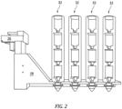
Fig. 2 is a schematic representation of X-ray tomography sample changing hardware. -
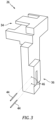
Fig. 3 is a schematic representation of an exemplary support bracket. -
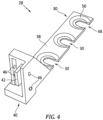
Fig. 4 is a schematic representation of an exemplary mounting arm. -
Fig. 5 is a rear isometric view schematic representation of an exemplary sample stage. -
Fig. 6 is a front isometric view schematic representation of an exemplary sample stage. -
Fig. 7 is a front isometric view schematic representation of an exemplary sample stage. -
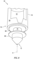
Fig. 8 is a front isometric view schematic representation of an exemplary sample stage lower section. -
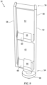
Fig. 9 is a front isometric view schematic representation of an exemplary sample stage. -
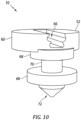
Fig. 10 is a front isometric view schematic representation of an exemplary sample stage lower portion. -
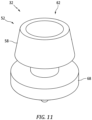
Fig. 11 is an isometric view schematic representation of an exemplary sample stage lower portion. -
Fig. 12 is a bottom isometric view schematic representation of an exemplary sample stage lower portion. - Referring now to
Fig. 1 andFig. 2 , there is illustrated anX-ray tomography system 10. Thetomography system 10 can includes anX-ray scanner 12. The X-ray scanner produces the necessary radiation and imaging capacity in thesystem 10. Asample manipulator 14 includes a multi-dimensional motion manipulation system configured to fetch samples and present the samples to thescanner 12 for imaging. - The
sample manipulator 14 includes areceiver 16 mounted on aturntable 18. Theturntable 18 is mounted on a sled 20 that can translate theturntable 18 laterally in multiple directions. The sled 20 is mounted on a table 22 that can travel vertically relative to thescanner 12. - A
scanner support 24 provides structural stability to asupport bracket 26. Thesupport bracket 26 attaches to amounting arm 28. Themounting arm 28 includesslots 30 configured to acceptsample stages 32. Theslots 30 can be C-shaped slots 30. - The
sample manipulator 14 is configured to locate thereceiver 16 into a position beneath each of thesample stages 32 located on themounting arm 28 in the C-shaped slots 30. Thesample manipulator 14 can retrieve thesample stage 32 and transport thesample stage 32 to a location in front of theX-ray scanner 12. Thesample manipulator 14 can rotate thesample stage 32 about theturntable 18 allowing for complete scanning on all sides o of thesample stage 32. Thesample manipulator 14 can then return thesample stage 32 back to the empty C-shaped slot 30 on themounting arm 28. Thesample manipulator 14 can repeat the process for each of thesample stages 32 mounted to themounting arm 28. - Referring also to
Fig. 3 details of theexemplary support bracket 26 are shown. Thesupport bracket 26 is configured to mount to existing X-ray tomography supports 24. Thesupport bracket 26 allows for interchangeable capability from different brands of X-ray tomography equipment. Thesupport bracket 26 can include anattachment feature 34 adapted to aparticular support 24. Thesupport bracket 26 includes asupport bracket receiver 36 that is adapted to receive the mountingarm 28. - Referring to
Fig. 4 details of the exemplary mountingarm 28 are shown. The mountingarm 28 includes abeam 38 having acoupling end 40. Thecoupling end 40 includes atab portion 42 that is configured to mate with thesupport bracket receiver 36 to secure the mountingarm 28 to thesupport bracket 26. A set ofpins 44 are insertable throughpin apertures 46 to secure the mountingarm 28 with thesupport bracket 26. The C-shaped slot(s) 30 can be arrayed along thebeam 38 of the mountingarm 28 in a spaced apart fashion to allow for ample spacing between the sample stages 32. Each C-shapedslot 30 includes amouth 48 that allows for thesample stage 32 to enter into/exit from the C-shapedslot 30. The C-shapedslot 30 includes aconcave surface 50 that nests thesample stage 32 within the C-shapedslot 30. The figures depict 3 C-shapedslots 30, however it is contemplated that multiple C-shapedslots 30 can be employed. The mountingarm 28 provides a rigid structure that locates the C-shapedslots 30 at fixed coordinates to facilitate thesample manipulator 14 being able to locate the sample stages 32 accurately for retrieval during an automated scanning procedure. - Referring also to
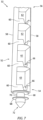
Fig. 5 through Fig. 8 details of anexemplary sample stage 32 are shown. Thesample stage 32 includes abody 52 having alower portion 54 and anupper portion 56 opposite thelower portion 54.Walls 58support shelves 60. Theshelves 60 andwalls 58 define asample chamber 62 configured to receive thesample part 64 to be scanned as seen inFig. 7 . Thesample chamber 62 can be sized to allow forparticular parts 64 to be placed into thesample chamber 62 and secured to theshelf 60. In an exemplary embodiment, as shown, theshelves 60 include mountingfeatures 66 configured to secure a portion of thepart 64 within thechamber 62. The mounting features 66 can be slots, grooves, notches, hollows, pins, hooks, latches, and the like. The mountingfeature 66 can be customized to receive a particular style ofpart 64, such as a fir tree portion of a root on a turbine blade. - The
sample chambers 62 are oriented axially (vertically) and allow for vertical stacking of theparts 64 in thesample stage 32. The vertical stacking configuration allows for maximizing the space available above the mountingarm 28. The axis A (Fig. 8 ) provides relative relationships to thebody 52. In this embodiment, the vertical orientation of thechambers 62 are along the axis A, that is axially. A radial direction is orthogonal to the axis A. - The
lower portion 54 of thesample stage 32 includesdual flanges 68 extending radially from ashaft 70. Theshaft 70 is oriented axially and is cylindrical in shape. Thedual flanges 68 are similarly circular shaped and extend radially from theshaft 70. Theshaft 70 anddual flanges 68 form a shape that matches the C-shapedslot 30. Theshaft 70 has a diameter sized to be insertable into/removeable from themouth 48 of the C-shapedslot 30. Thedual flanges 68 are sized larger than themouth 48 of the C-shapedslot 30 and configured to nest in theconcave surface 50 of the C-shapedslot 30. Thedual flanges 68 provide support and stability to thesample stage 32 when mounted within the C-shapedslot 30. - The
lower portion 54 includes acoupling 72 configured to mate with thereceiver 16 of thesample manipulator 14. Thecoupling 72 shown is a frustoconicalshaped coupling 72 that can match the concave shaped (cup, bowl)receiver 16. In other embodiments, thecoupling 72 can be concave shaped and thesample manipulator 14 can have areceiver 16 with a matching tapered frustoconical shape. The tapered shape of thecoupling 72 is configured to more easily mate with thereceiver 16 of thesample manipulator 14. - The exemplary embodiment shown in
Fig. 9 illustrates a configuration withchambers 62 that are rectilinear shaped. The mountingfeature 66 is shown to be rectilinear shaped. This embodiment demonstrates that thesample chamber 62 can be adapted tohouse sample parts 64 with a variety of shapes. - In an exemplary embodiment as shown in
Fig. 10 thesample stage 32 includes anabbreviated body 52 with ashelf 60 including a mountingfeature 66. The mountingfeature 66 is shown as an exemplary fir tree shape to receive the root of a blade. -
Fig. 11 andFig. 12 illustrate an exemplary embodiment with thesample stage 32 andsample chamber 62. Thesample stage 32 can include asample chamber 62 configured as an open container. Thechamber 62 shown is cylindrically shaped. Thebody 52side wall 58 is tapered with a larger diameter proximate theflange 68 and a smaller diameter distal from theflange 68. Thesample stage 32 can be utilized with certain shapedsample part 64. Thelower portion 54 includesflange 68 including an additionalaxial ring 74 extending axially from a radiallyoutermost portion 76 of theflange 68 to form a rightcircular cavity 78. Thecavity 78 can receive a portion of thereceiver 16. Theaxial ring 74 can include atapered lip 80. The taperedlip 80 can facilitate guiding thereceiver 16 into thecavity 78 and mating thesample stage 32 with thereceiver 16. - A technical advantage of the disclosed X-ray tomography sample changing hardware disclosed includes the capacity to image a wide breadth of part geometry for use with an X-ray tomography machine.
- Another technical advantage of the disclosed X-ray tomography sample changing hardware disclosed includes increased flexibility for imaging multiple types of parts.
- Another technical advantage of the disclosed X-ray tomography sample changing hardware disclosed includes optimizing X-ray tomography machines during overnight and weekend working hours.
- Another technical advantage of the disclosed X-ray tomography sample changing hardware disclosed includes a sample stage adapted to accept a large variety of physical geometries.
- Another technical advantage of the disclosed X-ray tomography sample changing hardware disclosed includes the capacity to vertically stack samples.
- There has been provided a X-ray tomography sample changing hardware. While the X-ray tomography sample changing hardware has been described in the context of specific embodiments thereof, other unforeseen alternatives, modifications, and variations may become apparent to those skilled in the art having read the foregoing description. Accordingly, it is intended to embrace those alternatives, modifications, and variations which fall within the broad scope of the appended claims.
Claims (15)
- An X-ray tomography sample changing hardware comprising:a support bracket configured to attach to an X-ray tomography support;a mounting arm attached to the support bracket, the mounting arm having a beam, at least one slot formed in the beam, the at least one slot including a mouth configured to receive a sample stage;the sample stage including a body having an axis with an upper portion and a lower portion axially opposite the upper portion; the lower portion configured to mate with a receiver on a sample manipulator for an X-ray tomography machine; andmultiple chambers formed in the body and aligned axially between the upper portion and the lower portion, each of the multiple chambers including a mounting feature configured to support a part within each of the multiple chambers.
- The X-ray tomography sample changing hardware according to claim 1, further comprising:an X-ray scanner proximate a scanner support;a sample manipulator in operative communication with the X-ray scanner; the sample manipulator including a receiver mounted on a turntable secured to a sled mounted on a table; anda support bracket configured to attach to the scanner support.
- The X-ray tomography sample changing hardware according to claim 1 or 2, wherein the body of the sample stage includes at least one wall, in particular a plurality of walls, formed in the body; the at least one wall, or the plurality of walls, supporting shelves defining each of the multiple chambers.
- The X-ray tomography sample changing hardware according to any of claims 1 to 3, wherein the at least one slot is arrayed along the beam of the mounting arm in a spaced apart fashion configured to allow for space between the sample stages supported on the mounting arm.
- The X-ray tomography sample changing hardware according to any of claims 1 to 4, wherein the multiple sample chambers are oriented axially and configured for vertical stacking of each part in the sample stage.
- The X-ray tomography sample changing hardware according to any of claims 1 to 5, wherein the lower portion of the sample stage includes at least one flange, in particular dual flanges, extending radially from a shaft formed in the body proximate the lower portion, the at least one flange, or the dual flanges, including a diameter sized to be insertable into/removeable from the mouth of the slot, the at least one flange, or the dual flanges, being sized larger than the mouth of the slot configured to nest in a concave surface of the slot.
- The X-ray tomography sample changing hardware according to any of claims 1 to 6, wherein the lower portion includes a coupling configured to mate with the receiver of the sample manipulator.
- The X-ray tomography sample changing hardware according to any of claims 1 to 7, wherein the mounting feature is selected from the group consisting of slots, grooves, notches, hollows, pins, hooks, latches, and the like.
- A process for supporting a part in an X-ray tomography sample changing hardware comprising:attaching a support bracket an X-ray tomography scanner support;attaching a mounting arm to the support bracket, the mounting arm having a beam, at least one slot formed in the beam, the at least one slot including a mouth configured to receive a sample stage;the sample stage including a body having an axis with an upper portion and a lower portion axially opposite the upper portion;mating the lower portion with a receiver on a sample manipulator for an X-ray tomography machine;forming multiple chambers in the body; andaligning the multiple chambers axially between the upper portion and the lower portion.
- The process of claim 9, further comprising:
supporting a part within at least one of the multiple chambers employing a mounting feature. - The process of claim 9 or 10, wherein the body of the sample stage includes walls formed in the body; and
defining each of the multiple chambers by employing shelves formed between the walls. - The process of any of claims 9 to 11, further comprising:
orienting the multiple sample chambers axially; and configuring the multiple chambers for vertical stacking of each part in the sample stage. - The process of any of claims 9 to 12, further comprising:
forming the mounting feature to accept a variety of part geometries, wherein the mounting feature is selected from the group consisting of slots, grooves, notches, hollows, pins, hooks, latches, and the like. - The process of any of claims 9 to 13, further comprising:
extending at least one flange radially from a shaft formed in the body proximate the lower portion, the shaft including a diameter sized to be insertable into/removeable from the mouth of the slot, the at least one flange being sized larger than the mouth of the slot configured to nest in a concave surface of the slot. - The process of claim 14, further comprising:
forming a coupling in the lower portion; the coupling configured to mate with the receiver of the sample manipulator.
Applications Claiming Priority (1)
| Application Number | Priority Date | Filing Date | Title |
|---|---|---|---|
| US18/216,072 US12571744B2 (en) | 2023-06-29 | 2023-06-29 | Hardware for automation of computer tomography sample changing |
Publications (2)
| Publication Number | Publication Date |
|---|---|
| EP4484937A1 true EP4484937A1 (en) | 2025-01-01 |
| EP4484937B1 EP4484937B1 (en) | 2026-04-29 |
Family
ID=91699871
Family Applications (1)
| Application Number | Title | Priority Date | Filing Date |
|---|---|---|---|
| EP24184407.5A Active EP4484937B1 (en) | 2023-06-29 | 2024-06-25 | Hardware for automation of computer tomography sample changing |
Country Status (2)
| Country | Link |
|---|---|
| US (1) | US12571744B2 (en) |
| EP (1) | EP4484937B1 (en) |
Families Citing this family (1)
| Publication number | Priority date | Publication date | Assignee | Title |
|---|---|---|---|---|
| US12571744B2 (en) * | 2023-06-29 | 2026-03-10 | Rtx Corporation | Hardware for automation of computer tomography sample changing |
Citations (3)
| Publication number | Priority date | Publication date | Assignee | Title |
|---|---|---|---|---|
| JP2005221460A (en) * | 2004-02-09 | 2005-08-18 | Shimadzu Corp | X-ray CT system |
| WO2020190919A1 (en) * | 2019-03-20 | 2020-09-24 | Carl Zeiss Smt Inc. | Sample holder, system and method |
| CN114544677A (en) * | 2022-03-02 | 2022-05-27 | 山东理工大学 | Intelligent sample changing system for CT scanning |
Family Cites Families (16)
| Publication number | Priority date | Publication date | Assignee | Title |
|---|---|---|---|---|
| US3920151A (en) | 1973-01-15 | 1975-11-18 | Atlantic Richfield Co | Automatic sample changer for positioning a plurality of pellets in an X-ray analyzer |
| US4803639A (en) | 1986-02-25 | 1989-02-07 | General Electric Company | X-ray inspection system |
| DE19839472C1 (en) | 1998-08-29 | 2000-11-02 | Bruker Axs Analytical X Ray Sy | Automatic sample changer for X-ray diffractometers |
| JP3426540B2 (en) | 1999-07-12 | 2003-07-14 | 理学電機工業株式会社 | Analysis system with sample changer |
| JP4488885B2 (en) * | 2004-12-17 | 2010-06-23 | 株式会社日立製作所 | CT equipment |
| US7627083B2 (en) * | 2007-03-13 | 2009-12-01 | VJ Technologies | Method and apparatus for automated, digital, radiographic inspection of aerospace parts |
| DE202013003922U1 (en) * | 2013-04-26 | 2013-05-13 | Carl Zeiss Industrielle Messtechnik Gmbh | Holding device for a computer tomography system |
| GB201508064D0 (en) * | 2015-05-12 | 2015-06-24 | Rolls Royce Plc | A method of scanning aerofoil blades |
| US10803574B2 (en) * | 2015-06-30 | 2020-10-13 | Illinois Tool Works Inc. | Inline x-ray measurement apparatus and method |
| US20170023495A1 (en) * | 2015-07-20 | 2017-01-26 | Apple Inc. | Universal computerized tomography fixture system with a multi-scan robotic positioning apparatus |
| US12007339B2 (en) * | 2019-03-20 | 2024-06-11 | Carl Zeiss Smt Inc. | Sample holder, system and method |
| DE202020103677U1 (en) * | 2019-03-26 | 2020-07-14 | Carl Zeiss Industrielle Messtechnik Gmbh | Holding device for a computer tomograph for holding at least one workpiece |
| PT115889B (en) * | 2019-11-04 | 2022-03-04 | Inst Politecnico De Leiria | MULTI-SAMPLE SUPPORT TO PERFORM MULTI-ANALYSIS IN A SINGLE SCAN IN COMPUTERIZED MICRO-TOMOGRAPHY |
| CN116710762A (en) * | 2021-01-12 | 2023-09-05 | 普罗托专利有限责任公司 | Laue measuring system with turntable and method of operation thereof |
| CN116297589A (en) * | 2022-09-07 | 2023-06-23 | 深圳晶泰科技有限公司 | XRD analysis equipment and system |
| US12571744B2 (en) * | 2023-06-29 | 2026-03-10 | Rtx Corporation | Hardware for automation of computer tomography sample changing |
-
2023
- 2023-06-29 US US18/216,072 patent/US12571744B2/en active Active
-
2024
- 2024-06-25 EP EP24184407.5A patent/EP4484937B1/en active Active
Patent Citations (3)
| Publication number | Priority date | Publication date | Assignee | Title |
|---|---|---|---|---|
| JP2005221460A (en) * | 2004-02-09 | 2005-08-18 | Shimadzu Corp | X-ray CT system |
| WO2020190919A1 (en) * | 2019-03-20 | 2020-09-24 | Carl Zeiss Smt Inc. | Sample holder, system and method |
| CN114544677A (en) * | 2022-03-02 | 2022-05-27 | 山东理工大学 | Intelligent sample changing system for CT scanning |
Also Published As
| Publication number | Publication date |
|---|---|
| US20250003894A1 (en) | 2025-01-02 |
| EP4484937B1 (en) | 2026-04-29 |
| US12571744B2 (en) | 2026-03-10 |
Similar Documents
| Publication | Publication Date | Title |
|---|---|---|
| EP4484937B1 (en) | Hardware for automation of computer tomography sample changing | |
| JP2021064784A (en) | Vertical batch furnace assembly | |
| US5861563A (en) | Automatic closed tube sampler | |
| US4057148A (en) | Multiple sample support assembly and apparatus for facilitating radioimmunoassays and the like | |
| US6871655B2 (en) | Automated semiconductor processing systems | |
| JP2021027353A (en) | Vertical batch furnace assembly | |
| JP2004214462A (en) | Substrate detection method and apparatus, and substrate processing apparatus | |
| US6758339B2 (en) | Thin wafer carrier | |
| JP2008526225A (en) | Milking equipment | |
| JP5893044B2 (en) | Storage device for incubator | |
| EP1477554A1 (en) | Culture device and storage container | |
| EP1642852B9 (en) | Slender-part feeding device | |
| JP2022514632A5 (en) | ||
| CN117485786A (en) | Biological sample warehouse-in and warehouse-out equipment | |
| CN223705561U (en) | Culture dish loading attachment and microorganism detection workstation | |
| CN220277046U (en) | Centrifuge tube taking and placing device of full-automatic cell harvester | |
| CN113624684A (en) | Pathological section scanner | |
| EP2148211A1 (en) | Apparatus and method for transferring electronic devices to and from a test position | |
| CN219122052U (en) | High-flux loading and unloading system | |
| CN216210214U (en) | A accurate feedway of carousel formula for microscope material loading | |
| US6877217B1 (en) | Apparatus for handling electrical components | |
| CN218169312U (en) | Automatic pin installation device and production line | |
| JP2002076108A (en) | Wafer cassette and method of storing wafer | |
| CN223059979U (en) | An automatic feeding device | |
| CN121404796B (en) | Annular material receiving system and method |
Legal Events
| Date | Code | Title | Description |
|---|---|---|---|
| PUAI | Public reference made under article 153(3) epc to a published international application that has entered the european phase |
Free format text: ORIGINAL CODE: 0009012 |
|
| STAA | Information on the status of an ep patent application or granted ep patent |
Free format text: STATUS: THE APPLICATION HAS BEEN PUBLISHED |
|
| AK | Designated contracting states |
Kind code of ref document: A1 Designated state(s): AL AT BE BG CH CY CZ DE DK EE ES FI FR GB GR HR HU IE IS IT LI LT LU LV MC ME MK MT NL NO PL PT RO RS SE SI SK SM TR |
|
| STAA | Information on the status of an ep patent application or granted ep patent |
Free format text: STATUS: REQUEST FOR EXAMINATION WAS MADE |
|
| 17P | Request for examination filed |
Effective date: 20250402 |
|
| GRAP | Despatch of communication of intention to grant a patent |
Free format text: ORIGINAL CODE: EPIDOSNIGR1 |
|
| STAA | Information on the status of an ep patent application or granted ep patent |
Free format text: STATUS: GRANT OF PATENT IS INTENDED |
|
| INTG | Intention to grant announced |
Effective date: 20260119 |
|
| RIN1 | Information on inventor provided before grant (corrected) |
Inventor name: KOCH, ROBERT Inventor name: PELLICCIONE, CHRISTOPHER JAMES Inventor name: HYDE, ELLIOT |
|
| GRAS | Grant fee paid |
Free format text: ORIGINAL CODE: EPIDOSNIGR3 |
|
| GRAA | (expected) grant |
Free format text: ORIGINAL CODE: 0009210 |
|
| STAA | Information on the status of an ep patent application or granted ep patent |
Free format text: STATUS: THE PATENT HAS BEEN GRANTED |
|
| AK | Designated contracting states |
Kind code of ref document: B1 Designated state(s): AL AT BE BG CH CY CZ DE DK EE ES FI FR GB GR HR HU IE IS IT LI LT LU LV MC ME MK MT NL NO PL PT RO RS SE SI SK SM TR |
|
| REG | Reference to a national code |
Ref country code: CH Ref legal event code: F10 Free format text: ST27 STATUS EVENT CODE: U-0-0-F10-F00 (AS PROVIDED BY THE NATIONAL OFFICE) Effective date: 20260429 Ref country code: GB Ref legal event code: FG4D |