EP4484901A1 - Sensor device and program - Google Patents
Sensor device and program Download PDFInfo
- Publication number
- EP4484901A1 EP4484901A1 EP23759864.4A EP23759864A EP4484901A1 EP 4484901 A1 EP4484901 A1 EP 4484901A1 EP 23759864 A EP23759864 A EP 23759864A EP 4484901 A1 EP4484901 A1 EP 4484901A1
- Authority
- EP
- European Patent Office
- Prior art keywords
- value
- circuit
- boost
- signal
- controller
- Prior art date
- Legal status (The legal status is an assumption and is not a legal conclusion. Google has not performed a legal analysis and makes no representation as to the accuracy of the status listed.)
- Pending
Links
Images


Classifications
-
- H—ELECTRICITY
- H02—GENERATION; CONVERSION OR DISTRIBUTION OF ELECTRIC POWER
- H02K—DYNAMO-ELECTRIC MACHINES
- H02K11/00—Structural association of dynamo-electric machines with electric components or with devices for shielding, monitoring or protection
- H02K11/20—Structural association of dynamo-electric machines with electric components or with devices for shielding, monitoring or protection for measuring, monitoring, testing, protecting or switching
- H02K11/21—Devices for sensing speed or position, or actuated thereby
-
- G—PHYSICS
- G01—MEASURING; TESTING
- G01D—MEASURING NOT SPECIALLY ADAPTED FOR A SPECIFIC VARIABLE; ARRANGEMENTS FOR MEASURING TWO OR MORE VARIABLES NOT COVERED IN A SINGLE OTHER SUBCLASS; TARIFF METERING APPARATUS; MEASURING OR TESTING NOT OTHERWISE PROVIDED FOR
- G01D3/00—Indicating or recording apparatus with provision for the special purposes referred to in the subgroups
- G01D3/08—Indicating or recording apparatus with provision for the special purposes referred to in the subgroups with provision for safeguarding the apparatus, e.g. against abnormal operation, against breakdown
-
- G—PHYSICS
- G01—MEASURING; TESTING
- G01D—MEASURING NOT SPECIALLY ADAPTED FOR A SPECIFIC VARIABLE; ARRANGEMENTS FOR MEASURING TWO OR MORE VARIABLES NOT COVERED IN A SINGLE OTHER SUBCLASS; TARIFF METERING APPARATUS; MEASURING OR TESTING NOT OTHERWISE PROVIDED FOR
- G01D5/00—Mechanical means for transferring the output of a sensing member; Means for converting the output of a sensing member to another variable where the form or nature of the sensing member does not constrain the means for converting; Transducers not specially adapted for a specific variable
- G01D5/12—Mechanical means for transferring the output of a sensing member; Means for converting the output of a sensing member to another variable where the form or nature of the sensing member does not constrain the means for converting; Transducers not specially adapted for a specific variable using electric or magnetic means
- G01D5/14—Mechanical means for transferring the output of a sensing member; Means for converting the output of a sensing member to another variable where the form or nature of the sensing member does not constrain the means for converting; Transducers not specially adapted for a specific variable using electric or magnetic means influencing the magnitude of a current or voltage
- G01D5/20—Mechanical means for transferring the output of a sensing member; Means for converting the output of a sensing member to another variable where the form or nature of the sensing member does not constrain the means for converting; Transducers not specially adapted for a specific variable using electric or magnetic means influencing the magnitude of a current or voltage by varying inductance, e.g. by a movable armature
- G01D5/204—Mechanical means for transferring the output of a sensing member; Means for converting the output of a sensing member to another variable where the form or nature of the sensing member does not constrain the means for converting; Transducers not specially adapted for a specific variable using electric or magnetic means influencing the magnitude of a current or voltage by varying inductance, e.g. by a movable armature by influencing the mutual induction between two or more coils
-
- G—PHYSICS
- G01—MEASURING; TESTING
- G01K—MEASURING TEMPERATURE; MEASURING QUANTITY OF HEAT; THERMALLY-SENSITIVE ELEMENTS NOT OTHERWISE PROVIDED FOR
- G01K13/00—Thermometers specially adapted for specific purposes
-
- G—PHYSICS
- G01—MEASURING; TESTING
- G01K—MEASURING TEMPERATURE; MEASURING QUANTITY OF HEAT; THERMALLY-SENSITIVE ELEMENTS NOT OTHERWISE PROVIDED FOR
- G01K7/00—Measuring temperature based on the use of electric or magnetic elements directly sensitive to heat ; Power supply therefor, e.g. using thermoelectric elements
- G01K7/01—Measuring temperature based on the use of electric or magnetic elements directly sensitive to heat ; Power supply therefor, e.g. using thermoelectric elements using semiconducting elements having PN junctions
-
- H—ELECTRICITY
- H02—GENERATION; CONVERSION OR DISTRIBUTION OF ELECTRIC POWER
- H02K—DYNAMO-ELECTRIC MACHINES
- H02K11/00—Structural association of dynamo-electric machines with electric components or with devices for shielding, monitoring or protection
- H02K11/20—Structural association of dynamo-electric machines with electric components or with devices for shielding, monitoring or protection for measuring, monitoring, testing, protecting or switching
- H02K11/25—Devices for sensing temperature, or actuated thereby
-
- H—ELECTRICITY
- H02—GENERATION; CONVERSION OR DISTRIBUTION OF ELECTRIC POWER
- H02M—APPARATUS FOR CONVERSION BETWEEN AC AND AC, BETWEEN AC AND DC, OR BETWEEN DC AND DC, AND FOR USE WITH MAINS OR SIMILAR POWER SUPPLY SYSTEMS; CONVERSION OF DC OR AC INPUT POWER INTO SURGE OUTPUT POWER; CONTROL OR REGULATION THEREOF
- H02M1/00—Details of apparatus for conversion
- H02M1/08—Circuits specially adapted for the generation of control voltages for semiconductor devices incorporated in static converters
-
- H—ELECTRICITY
- H02—GENERATION; CONVERSION OR DISTRIBUTION OF ELECTRIC POWER
- H02M—APPARATUS FOR CONVERSION BETWEEN AC AND AC, BETWEEN AC AND DC, OR BETWEEN DC AND DC, AND FOR USE WITH MAINS OR SIMILAR POWER SUPPLY SYSTEMS; CONVERSION OF DC OR AC INPUT POWER INTO SURGE OUTPUT POWER; CONTROL OR REGULATION THEREOF
- H02M1/00—Details of apparatus for conversion
- H02M1/32—Means for protecting converters other than automatic disconnection
- H02M1/327—Means for protecting converters other than automatic disconnection against abnormal temperatures
-
- G—PHYSICS
- G01—MEASURING; TESTING
- G01K—MEASURING TEMPERATURE; MEASURING QUANTITY OF HEAT; THERMALLY-SENSITIVE ELEMENTS NOT OTHERWISE PROVIDED FOR
- G01K2205/00—Application of thermometers in motors, e.g. of a vehicle
Definitions
- the present disclosure relates to a sensor device and a program.
- Patent Literature 1 JP 2017-106931 A
- Patent Literature 1 when the temperature of the element falls outside a normal operating range, the pulse signals are stuck high or low, which makes it impossible to detect the temperature correctly. Thus, the temperature detecting device outputs fail signals and stops detecting the temperature.
- the temperature detecting device may output fail signals even when the temperature sensor operates properly.
- the temperature of the element is recognized as being outside the normal operating range and a normal control for an inverter and the like cannot be maintained. Similar situations may occur with sensors other than the temperature sensor. It is an objective of this disclosure to provide a sensor device that can avoid erroneous detection of the state of a detection target and a program thereof.
- the sensor device of the present disclosure includes a boost circuit, an internal power supply, and a controller.
- the boost circuit is configured to increase a voltage from a battery.
- the internal power supply is configured to supply the voltage that is increased by the boost circuit.
- the controller includes a drive signal generating unit configured to generate a boost-circuit drive signal for driving the boost circuit, and a calculating unit configured to calculate a value in accordance with a state of a detection target based on a sensor signal that is generated using the internal power supply to obtain a calculated value.
- the controller is further configured to use a substitute value as an internal recognition value of the state of the detection target instead of the calculated value based on the sensor signal when turning off the boost-circuit drive signal to stop the boost circuit. This makes it possible to avoid erroneous detection of the state of the detection target.
- the present disclosure is also provided as a program for a sensor device.
- the program is configured to cause at least one controller to generate a boost-circuit drive signal for driving a boost circuit, calculate a value in accordance with a state of a detection target based on a sensor signal that is generated using an internal power supply to obtain a calculated value.
- the internal power supply supplies a voltage increased by the boost circuit.
- the program is further configured to cause the at least one controller to use a substitute value as an internal recognition value of the state of the detection target instead of the calculated value based on the sensor signal when turning off the boost-circuit drive signal to stop the boost circuit. This provides similar effects as the sensor device.
- a vehicle drive system 1 includes a main battery 5, an auxiliary battery 7, a main motor 10, a power control unit 20, and the like.
- the main battery 5 is a direct current power source including a rechargeable secondary battery such as a nickel hydrogen battery or a lithium ion battery.
- the power of the main battery 5 is supplied with the main motor 10 mainly via a bridge circuit 22 and is used to drive the main motor 10.
- the main battery 5 is charged by electric power regenerated by the main motor 10.
- the main battery 5 can be also charged by an external power source (not shown).
- the auxiliary battery 7 is a secondary battery such as a lead storage battery, and supplies power with a control unit 30 and auxiliary devices (not shown).
- the main motor 10 is a permanent magnet synchronous motor that uses three-phase alternating current.
- the main motor 10 is a so-called "motor generator” that has functions both as an electric motor and as a generator.
- the main motor 10 is used as a driving source for the vehicle.
- the vehicle may be an electric vehicle that drives only by the driving force of the main motor 10, or a hybrid vehicle that drives by the driving force of both the main motor 10 and an engine (not shown).
- the main motor 10 is provided with a resolver 15 which is a rotation angle sensor that detects an angle of rotation.
- the controller 50 is mainly composed of a microcontroller, and internally includes a CPU, a ROM, a RAM, an I/O, and a bus line (not shown) for connecting these components.
- Each processing executed by the controller 50 may be software processing which is implemented by causing the CPU to execute a program stored in a memory device such as a ROM (i.e., computer-readable non-transitory tangible storage medium) or may be hardware processing which is implemented by a special purpose electronic circuit.
- the controller 50 is supplied with power from the auxiliary battery 7 via a regulator (not shown) without through the boost circuit 31.
- the controller 50 has, as functional blocks, a drive signal generating unit 51, an angle calculating unit 52, a temperature calculating unit 53, a voltage monitoring unit 55.
- the drive signal generating unit 51 is configured to generate a boost-circuit drive signal for driving the boost circuit 31, and to output the boost-circuit drive signal to the boost circuit 31.
- the temperature calculating unit 53 obtains a temperature detection signal, which is generated depending on the temperature of the inverter element, from the gate driver IC 47, and calculates the temperature of the inverter element based on the duty of the obtained temperature detection signal.
- the voltage monitoring unit 55 obtains a converted voltage that is obtained by converting the power voltage of the first internal power supply 41, which is used by the resolver excitation circuit 45, to fall within a predetermined range (for example, 0 v to 5 v). The voltage monitoring unit 55 monitors whether the first internal power supply 41 operates within a normal range using the converted voltage.
- the resolver excitation circuit 45 and the gate driver IC 47 require a voltage higher than that of the auxiliary battery 7.
- the power generated by the boost circuit 31 is supplied to the resolver excitation circuit 45 through the internal power supplies 41, 42.
- EMC Electromagnetic Compatibility
- the controller 50 keeps operating while the boost circuit 31 is stopped.
- the controller 50 may erroneously determine that the temperature of the inverter element is out of the normal range even when the actual temperature of the inverter element is within the normal range.
- the controller 50 uses a substitute value as an internal recognition value of the microcontroller instead of using a calculated value based on the sensor signal that is generated using the internal power supplies 41, 42.
- the sensor signal that is generated using the internal power supply does not only refer to cases where the power of the internal power supplies 41, 42 is used to operate the sensor itself, and also refer to cases where the power of the internal power supplies 41, 42 is used for outputting signals from the sensor to the controller 50.
- a sensor that uses the power of the internal power supplies 41, 42 to generate a sensor signal will be referred to as a "increased-voltage using sensor". It should be noted that calculation based on detection signals from sensors other than the increased-voltage using sensor may continue even when the boost circuit 31 is stopped.
- the controller 50 uses a substitute value (e.g., 0) as the internal recognition value instead of the calculated value that is calculated based on the resolver signal.
- a substitute value e.g., 0
- the substitute value may be the previous value or a preset value.
- the processing proceeds to S105 and the controller 50 determines whether the boost circuit 31 is operating or not.
- the controller 50 determines that the boost circuit 31 is operating (S105: YES)
- the controller 50 skips S106 and subsequent steps and keeps operating the boost circuit 31.
- the processing proceeds to S106.
- the drive signal generating unit 51 turns on the boost circuit driving signal to start operation of the boost circuit 31.
- the controller 50 may determine that the recovery condition is met upon receiving a notification that a function which is activated after the boost circuit 31 starts operating has been activated. As a function that is activated after the start of the boost circuit 31, the controller 50 may determine that the recovery condition is met when the voltage of the first internal power supply falls within a normal range. Furthermore, the controller 50 may determine that the recovery condition is met when the excitation periodic signal obtained from the resolver excitation circuit 45 has a normal amplitude and period.
- the controller 50 determines that the recovery condition for the increased-voltage using sensor is not satisfied (S107: NO).
- this determination process is repeated.
- the controller 50 determines that the recovery condition is satisfied (S107: YES)
- the processing proceeds to S108 and the controller 50 starts calculation of detection value based on the sensor signal and uses the calculated value as the internal recognition value.
- the controller 50 stars to calculate the temperature of the inverter element based on the temperature detection signal that is generated from the gate driver IC 47, starts to detect the power voltage of the resolver excitation circuit 45, and starts to calculate the angle of the main motor 10 based on the resolver signal.
- the controller 50 may continue the calculation or start the calculation before the recovery condition is met and may start to use the calculated value as the internal recognition value of the microcomputer at the timing when the recovery condition is met.
- the horizontal axis represents the common time axis.
- the charging status of the main battery 5 the operation status of the boost circuit 31, the power voltage of the gate driver IC 47, the internal recognition value of the inverter element temperature in the microcontroller, the actual inverter element temperature, and the pulse signal from the gate driver IC 47 are shown from the top.
- FIG. 4 as an example for sensor value calculation of the increased-voltage using sensor, an element temperature calculation based on the temperature detection signal from the gate driver IC 47 is shown.
- the temperature calculating unit 53 calculates the temperature of the inverter element based on the duty of the temperature detection signal output from the gate driver IC 47.
- the calculated temperature of the inverter element is almost consistent with the actual temperature of the inverter element.
- the drive signal generating unit 51 deactivates the boost-circuit drive signal and stops operation of the boost circuit 31.
- the boost circuit 31 stops, the second internal power supply 42 that is the power supply for the gate driver IC 47 stops, and the temperature detection signal from the gate driver IC 47 also stops. Therefore, when the controller 50 continues calculating the element temperature based on the signal from the gate driver IC 47, the controller 50 may erroneously recognize that the temperature of the inverter element is outside of the normal range even though the actual temperature of the inverter element falls within the normal range.
- the drive signal generating unit 51 activates the boost-circuit drive signal at time x13, and the operation of the boost circuit 31 starts.
- the boost circuit 31 starts operating, the second internal power supply 42 starts up and the power supply of the gate driver IC 47 is restored.
- the temperature calculating unit 53 starts to calculate the temperature and to use the calculated value again as the internal recognition value instead of the substitute value at time x14 when the waiting time Xt has elapsed after the boost-circuit drive signal is activated. This enables to avoid obtaining a temperature that is different from the actual temperature due to a delay between when the boost circuit 31 starts operation and when the pulse signal becomes stable.
- the controller 50 includes the drive signal generating unit 51 and the calculating unit.
- the drive signal generating unit 51 generates a boost-circuit drive signal for driving the boost circuit 31 .
- the calculating unit is capable of calculating a value in accordance with the state of the detection target based on a sensor signal that is generated using the internal power supplies 41 and 42.
- the controller 50 uses the substitute value as the internal recognition value of the state of the detection target of the controller 50 instead of using the calculated value based on the sensor signal. Stopping the boost circuit 31 causes abnormal behavior of the sensor signal, which further causes erroneous detection of the state of the detection target based on the sensor signal. Using the substitute value can avoid such erroneous detection.
- substitute values are used to represent the values related to the inverter element temperature, the power voltage of the resolver excitation circuit, and the rotational position of the main motor.
- some of the values for which substitute values are used when the boost circuit is stopped may be omitted, or other calculated values related to the increased-voltage using sensor may be replaced with the substitute values.
- a substitute value is used instead of using the detection value of the increased-voltage using sensor.
- a substitute value may be used instead of the detection value of the increased-voltage using sensor.
- the controller and method described in the present disclosure may be implemented by a special purpose computer which is configured with a memory and a processor programmed to execute one or more particular functions embodied in computer programs of the memory.
- the controller described in the present disclosure and the method thereof may be implemented by a dedicated computer configured as a processor with one or more dedicated hardware logic circuits.
- the controller and the method described in the present disclosure may be realized by one or more dedicated computer, which is configured as a combination of a processor and a memory, which are programmed to perform one or more functions, and a processor which is configured with one or more hardware logic circuits.
- the computer programs may be stored, as instructions to be executed by a computer, in a tangible non-transitory computer-readable medium.
Landscapes
- Engineering & Computer Science (AREA)
- Power Engineering (AREA)
- Microelectronics & Electronic Packaging (AREA)
- Physics & Mathematics (AREA)
- General Physics & Mathematics (AREA)
- Inverter Devices (AREA)
- Control Of Ac Motors In General (AREA)
- Electric Propulsion And Braking For Vehicles (AREA)
Abstract
Description
- The present application is based on
Japanese Patent Application No. 2022-027969 filed on February 25, 2022 - The present disclosure relates to a sensor device and a program.
- Conventionally, there is a temperature detecting device that detects the temperature of an inverter element. For example,
Japanese Patent Literature 1 discloses a temperature detecting device that transmits pulse signals depending on the temperature detected by a temperature sensor to an integrated circuit. - Patent Literature 1:
JP 2017-106931 A - In
Patent Literature 1, when the temperature of the element falls outside a normal operating range, the pulse signals are stuck high or low, which makes it impossible to detect the temperature correctly. Thus, the temperature detecting device outputs fail signals and stops detecting the temperature. - Here, when the power supply for an output device of a detection value of the temperature sensor is stopped, the temperature detecting device may output fail signals even when the temperature sensor operates properly. In this case, the temperature of the element is recognized as being outside the normal operating range and a normal control for an inverter and the like cannot be maintained. Similar situations may occur with sensors other than the temperature sensor. It is an objective of this disclosure to provide a sensor device that can avoid erroneous detection of the state of a detection target and a program thereof.
- The sensor device of the present disclosure includes a boost circuit, an internal power supply, and a controller. The boost circuit is configured to increase a voltage from a battery. The internal power supply is configured to supply the voltage that is increased by the boost circuit. The controller includes a drive signal generating unit configured to generate a boost-circuit drive signal for driving the boost circuit, and a calculating unit configured to calculate a value in accordance with a state of a detection target based on a sensor signal that is generated using the internal power supply to obtain a calculated value. The controller is further configured to use a substitute value as an internal recognition value of the state of the detection target instead of the calculated value based on the sensor signal when turning off the boost-circuit drive signal to stop the boost circuit. This makes it possible to avoid erroneous detection of the state of the detection target.
- The present disclosure is also provided as a program for a sensor device. The program is configured to cause at least one controller to generate a boost-circuit drive signal for driving a boost circuit, calculate a value in accordance with a state of a detection target based on a sensor signal that is generated using an internal power supply to obtain a calculated value. The internal power supply supplies a voltage increased by the boost circuit. The program is further configured to cause the at least one controller to use a substitute value as an internal recognition value of the state of the detection target instead of the calculated value based on the sensor signal when turning off the boost-circuit drive signal to stop the boost circuit. This provides similar effects as the sensor device.
- The above and other objects, features and advantages of the present disclosure will become more apparent from the following detailed description made with reference to the accompanying drawings. In the drawings:
-
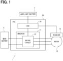
FIG. 1 is a block diagram illustrating a configuration of a vehicle drive system according to one embodiment; -
FIG. 2 is a block diagram illustrating a control unit according to the embodiment; -
FIG. 3 is a flowchart for processing of calculating a sensor value according to the embodiment; and -
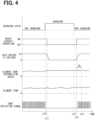
FIG. 4 is a time chart for explaining the processing of calculating a sensor value according to the embodiment. - Hereinafter, a sensor device and a program according to the present disclosure will be described with reference to the drawings. An embodiment is shown in
FIGS. 1 to 4 . As shown inFIG. 1 , avehicle drive system 1 includes amain battery 5, anauxiliary battery 7, amain motor 10, apower control unit 20, and the like. - The
main battery 5 is a direct current power source including a rechargeable secondary battery such as a nickel hydrogen battery or a lithium ion battery. The power of themain battery 5 is supplied with themain motor 10 mainly via abridge circuit 22 and is used to drive themain motor 10. Themain battery 5 is charged by electric power regenerated by themain motor 10. Themain battery 5 can be also charged by an external power source (not shown). Theauxiliary battery 7 is a secondary battery such as a lead storage battery, and supplies power with acontrol unit 30 and auxiliary devices (not shown). - The
main motor 10 is a permanent magnet synchronous motor that uses three-phase alternating current. Themain motor 10 is a so-called "motor generator" that has functions both as an electric motor and as a generator. Themain motor 10 is used as a driving source for the vehicle. The vehicle may be an electric vehicle that drives only by the driving force of themain motor 10, or a hybrid vehicle that drives by the driving force of both themain motor 10 and an engine (not shown). Themain motor 10 is provided with aresolver 15 which is a rotation angle sensor that detects an angle of rotation. - As shown in
FIGS. 1 and2 , thepower control unit 20 includes aninverter 21, thecontrol unit 30, and the like. Theinverter 21 includes thebridge circuit 22 and atemperature sensor 25. Thebridge circuit 22 has inverter elements (e.g., IGBTs) which are connected in a bridge configuration. Thebridge circuit 22 converts the direct current power supplied from themain battery 5 into three-phase alternating current power, and outputs the alternating current power to themain motor 10. Thetemperature sensor 25 detects the temperature of the inverter elements that form thebridge circuit 22. In the drawing, the power control unit is abbreviated as "PCU" and the control unit is abbreviated as "ECU." - As shown in
FIG. 2 , thecontrol unit 30 includes aboost circuit 31, a firstinternal power supply 41, a secondinternal power supply 42, aresolver excitation circuit 45, a gate driver integrated circuit (IC) 47, and acontroller 50. Thecontrol unit 30 operates using power of theauxiliary battery 7. Theboost circuit 31 has a boost element such as an IGBT and switches the boost element to increase the voltage of the auxiliary battery 7 (e.g., 12 V). Theboost circuit 31 generates increased voltages for the firstinternal power source 41 and the secondinternal power source 42. In this embodiment, the firstinternal power supply 41 is, for example, a 30 V power supply, and the second internal power supply is, for example, a 17 V power supply, but the number of internal power supplies and the increased voltage may be different. - The
resolver excitation circuit 45 generates a resolver excitation signal using power supplied from the firstinternal power supply 41. The generated resolver excitation signal is output to theresolver 15. Theresolver 15 uses the resolver excitation signal to output a sine signal and a cosine signal to thecontroller 50. The sine signal and the cosine signal are angle signals in accordance with the rotational position of themain motor 10. Further, a resolver digital converter (RDC) 16 calculates an angle based on the sine signal and the cosine signal output from theresolver 15, and outputs digital signals in accordance with the calculated angle to thecontroller 50. Hereinafter, the sine signal and the cosine signal output from theresolver 15 will be referred to as resolver signals. - The
gate driver IC 47 is supplied with power from the secondinternal power supply 42 and outputs a gate signal to theinverter 21. Furthermore, thegate driver IC 47 obtains values such as a detection value of thetemperature sensor 25 and a detection value of a current sensor (not shown) as inverter element information. Thegate driver IC 47 outputs a temperature detection signal, which is a pulse signal whose duty is changed depending on the temperature of the inverter element, to thecontroller 50. - The
controller 50 is mainly composed of a microcontroller, and internally includes a CPU, a ROM, a RAM, an I/O, and a bus line (not shown) for connecting these components. Each processing executed by thecontroller 50 may be software processing which is implemented by causing the CPU to execute a program stored in a memory device such as a ROM (i.e., computer-readable non-transitory tangible storage medium) or may be hardware processing which is implemented by a special purpose electronic circuit. Thecontroller 50 is supplied with power from theauxiliary battery 7 via a regulator (not shown) without through theboost circuit 31. - The
controller 50 has, as functional blocks, a drivesignal generating unit 51, anangle calculating unit 52, atemperature calculating unit 53, avoltage monitoring unit 55. The drivesignal generating unit 51 is configured to generate a boost-circuit drive signal for driving theboost circuit 31, and to output the boost-circuit drive signal to theboost circuit 31. - The
angle calculating unit 52 obtains AD converted values of the sine signal and the cosine signal output from theresolver 15, and calculates information relating to the rotational position of themain motor 10 by arctangent function and the like. The information relating to the rotational position of themain motor 10 includes the rotation speed, the resolver angle, and the electrical angle. - The
temperature calculating unit 53 obtains a temperature detection signal, which is generated depending on the temperature of the inverter element, from thegate driver IC 47, and calculates the temperature of the inverter element based on the duty of the obtained temperature detection signal. Thevoltage monitoring unit 55 obtains a converted voltage that is obtained by converting the power voltage of the firstinternal power supply 41, which is used by theresolver excitation circuit 45, to fall within a predetermined range (for example, 0 v to 5 v). Thevoltage monitoring unit 55 monitors whether the firstinternal power supply 41 operates within a normal range using the converted voltage. - The
resolver excitation circuit 45 and thegate driver IC 47 require a voltage higher than that of theauxiliary battery 7. Thus, the power generated by theboost circuit 31 is supplied to theresolver excitation circuit 45 through theinternal power supplies - When the
boost circuit 31 increases the voltage, the boost element is switched, which generates noise. Furthermore, as vehicles are becoming more electrified, Electromagnetic Compatibility (EMC) requirements tends to become stricter. For example, when theboost circuit 31 is operating during a charge of themain battery 5 by an external power source, the EMC requirements may not be met due to the switching noise. - Therefore, in this embodiment, while the
main battery 5 is charged, the operation of theboost circuit 31 is stopped. When theboost circuit 31 is stopped, theresolver excitation circuit 45 and thegate driver IC 47 which operates using power from theinternal power supplies - On the other hand, power is supplied with the
controller 50 without through theboost circuit 31. Thus, thecontroller 50 keeps operating while theboost circuit 31 is stopped. In this case, when thecontroller 50 continues detecting the temperature of the inverter element based on the temperature detection signal that is generated by thegate driver IC 47, thecontroller 50 may erroneously determine that the temperature of the inverter element is out of the normal range even when the actual temperature of the inverter element is within the normal range. - Thus, in this embodiment, when the
boost circuit 31 is appropriately stopped by an instruction from thecontroller 50 for charging themain battery 5 and the like, thecontroller 50 uses a substitute value as an internal recognition value of the microcontroller instead of using a calculated value based on the sensor signal that is generated using theinternal power supplies internal power supplies internal power supplies controller 50. Hereinafter, a sensor that uses the power of theinternal power supplies boost circuit 31 is stopped. - The processing of calculating the sensor value of the present embodiment will be described with reference to the flowchart of
FIG. 3 . This processing is executed by thecontroller 50 at a predetermined cycle. Hereinafter, "step" may be simply referred to as a symbol "S." - In S101, the
controller 50 obtains charging information related to the charging state of themain battery 5 from the vehicle system. In S102, thecontroller 50 determines whether themain battery 5 is being charged by an external power source. When thecontroller 50 determines that themain battery 5 is being charged (S102: YES), the processing proceeds to S103. The charging in this step does not mean charging by regeneration and themain motor 10 is stopped. When thecontroller 50 determines that themain battery 5 is not been charged (S102: NO), the processing proceeds to S105. - In S103, the drive
signal generating unit 51 turns off the boost-circuit drive signal to stop theboost circuit 31. In S104, thecontroller 50 uses the substitute value as the internal recognition value in the microcontroller of the increased-voltage using sensor. - When the
boost circuit 31 is stopped, the temperature detection signal that is generated by thegate driver IC 47 is stopped. Thus, thecontroller 50 may erroneously recognize that the temperature of the inverter element is out of the normal range even though the actual temperature of the inverter element is within the normal range. Therefore, to prevent erroneous detection of the temperature of the inverter element, when theboost circuit 31 is stopped, thecontroller 50 keeps the previous value as the internal recognition value instead of the calculated value that is calculated based on the temperature detection signal generated by the gate driver IC. - When the
boost circuit 31 is stopped, the voltage of the firstinternal power supply 41, which is the power supply for theresolver excitation circuit 45, is 0 V. Thus, thecontroller 50 may erroneously recognize that theresolver excitation circuit 45 is out of normal operation. In order to prevent erroneous detection of the power voltage of theresolver excitation circuit 45, when theboost circuit 31 is stopped, thecontroller 50 uses a substitute value as the internal recognition value instead of the detected value of the power voltage. - Furthermore, when the
boost circuit 31 is stopped, the resolver excitation signal is stopped and the resolver signal becomes unstable, which may cause unstable rotational position of themain motor 10. Therefore, in order to prevent erroneous detection of the rotational position of themain motor 10, when theboost circuit 31 is stopped, thecontroller 50 uses a substitute value (e.g., 0) as the internal recognition value instead of the calculated value that is calculated based on the resolver signal. It should be noted that what is shown here is merely an example, and it is possible to appropriately select what is used as the internal recognition value. The substitute value may be the previous value or a preset value. - When the
main battery 5 is not being charged (S102: NO), the processing proceeds to S105 and thecontroller 50 determines whether theboost circuit 31 is operating or not. When thecontroller 50 determines that theboost circuit 31 is operating (S105: YES), thecontroller 50 skips S106 and subsequent steps and keeps operating theboost circuit 31. When thecontroller 50 determines that theboost circuit 31 is stopped (S105: NO), the processing proceeds to S106. In S106, the drivesignal generating unit 51 turns on the boost circuit driving signal to start operation of theboost circuit 31. - In S107, the
controller 50 determines whether a recovery condition for the increased-voltage using sensor is met. For example, thecontroller 50 may determine that the recovery condition is met when a waiting time Xt has elapsed from the start of the operation of theboost circuit 31. The waiting time Xt can be set according to the time required to stabilize the voltages of theinternal power supplies boost circuit 31. - Alternatively, the
controller 50 may determine that the recovery condition is met upon receiving a notification that a function which is activated after theboost circuit 31 starts operating has been activated. As a function that is activated after the start of theboost circuit 31, thecontroller 50 may determine that the recovery condition is met when the voltage of the first internal power supply falls within a normal range. Furthermore, thecontroller 50 may determine that the recovery condition is met when the excitation periodic signal obtained from theresolver excitation circuit 45 has a normal amplitude and period. - When the
controller 50 determines that the recovery condition for the increased-voltage using sensor is not satisfied (S107: NO), this determination process is repeated. When thecontroller 50 determines that the recovery condition is satisfied (S107: YES), the processing proceeds to S108 and thecontroller 50 starts calculation of detection value based on the sensor signal and uses the calculated value as the internal recognition value. In detail, thecontroller 50 stars to calculate the temperature of the inverter element based on the temperature detection signal that is generated from thegate driver IC 47, starts to detect the power voltage of theresolver excitation circuit 45, and starts to calculate the angle of themain motor 10 based on the resolver signal. Thecontroller 50 may continue the calculation or start the calculation before the recovery condition is met and may start to use the calculated value as the internal recognition value of the microcomputer at the timing when the recovery condition is met. - The processing of calculating sensor values in the present embodiment will be described with reference to the time chart in
FIG. 4 . InFIG. 4 , the horizontal axis represents the common time axis. In the vertical axis ofFIG. 4 , the charging status of themain battery 5, the operation status of theboost circuit 31, the power voltage of thegate driver IC 47, the internal recognition value of the inverter element temperature in the microcontroller, the actual inverter element temperature, and the pulse signal from thegate driver IC 47 are shown from the top. In addition, inFIG. 4 , as an example for sensor value calculation of the increased-voltage using sensor, an element temperature calculation based on the temperature detection signal from thegate driver IC 47 is shown. - Before time x10, the
main battery 5 is not being charged and theboost circuit 31 is operating normally. Thus, thetemperature calculating unit 53 calculates the temperature of the inverter element based on the duty of the temperature detection signal output from thegate driver IC 47. The calculated temperature of the inverter element is almost consistent with the actual temperature of the inverter element. - When the
main battery 5 starts to be charged at time x10, the drivesignal generating unit 51 deactivates the boost-circuit drive signal and stops operation of theboost circuit 31. When theboost circuit 31 stops, the secondinternal power supply 42 that is the power supply for thegate driver IC 47 stops, and the temperature detection signal from thegate driver IC 47 also stops. Therefore, when thecontroller 50 continues calculating the element temperature based on the signal from thegate driver IC 47, thecontroller 50 may erroneously recognize that the temperature of the inverter element is outside of the normal range even though the actual temperature of the inverter element falls within the normal range. - Therefore, in this embodiment, the
temperature calculating unit 53 stops calculating the temperature based on the temperature detection signal from thegate driver IC 47 and uses the substitute value as the internal recognition value of the temperature of the inverter element. In detail, after the time x11 when the boost-circuit drive signal is turned off, the previous value is held as the substitute value. As a result, the microcontroller recognizes that the inverter element temperature is within the normal range. Thus, thecontroller 50 can recognize that theinverter 21 operates normally and continue the control when themain motor 10 is restarted after completion of the charge of themain battery 5. - When charging of the
main battery 5 is completed at time x12, the drivesignal generating unit 51 activates the boost-circuit drive signal at time x13, and the operation of theboost circuit 31 starts. When theboost circuit 31 starts operating, the secondinternal power supply 42 starts up and the power supply of thegate driver IC 47 is restored. There is a delay between when theboost circuit 31 is started and when thegate driver IC 47 becomes able to correctly output a temperature detection signal. In this embodiment, taking into consideration the delay from the start of operation of theboost circuit 31, thetemperature calculating unit 53 starts to calculate the temperature and to use the calculated value again as the internal recognition value instead of the substitute value at time x14 when the waiting time Xt has elapsed after the boost-circuit drive signal is activated. This enables to avoid obtaining a temperature that is different from the actual temperature due to a delay between when theboost circuit 31 starts operation and when the pulse signal becomes stable. - As described above, the
control unit 30 includes theboost circuit 31, theinternal power supplies controller 50. Theboost circuit 31 increases the voltage from theauxiliary battery 7. Theinternal power supplies boost circuit 31. - The
controller 50 includes the drivesignal generating unit 51 and the calculating unit. The drivesignal generating unit 51 generates a boost-circuit drive signal for driving theboost circuit 31 . The calculating unit is capable of calculating a value in accordance with the state of the detection target based on a sensor signal that is generated using theinternal power supplies controller 50 properly stops the operation of theboost circuit 31 by turning off the boost-circuit drive signal, thecontroller 50 uses the substitute value as the internal recognition value of the state of the detection target of thecontroller 50 instead of using the calculated value based on the sensor signal. Stopping theboost circuit 31 causes abnormal behavior of the sensor signal, which further causes erroneous detection of the state of the detection target based on the sensor signal. Using the substitute value can avoid such erroneous detection. - When the
controller 50 turns on the boost-circuit drive signal and starts operating theboost circuit 31, and further when the recovery condition is met, thecontroller 50 starts to use the calculated value based on the sensor signal again instead of using the substitute value. This enables to avoid erroneous detection of the state of the detection target caused by the delay between when theboost circuit 31 is started and when the sensor signal becomes normal. - The detection target is the
inverter 21. Thetemperature calculating unit 53 obtains as a sensor signal a temperature detection signal, which is generated depending on the temperature of the inverter element, from thegate driver IC 47. The inverter element forms theinverter 21 and thegate driver IC 47 outputs a gate signal to theinverter 21. Thetemperature calculating unit 53 calculates the temperature of the inverter element based on the sensor signal. When theboost circuit 31 is properly stopped, thecontroller 50 uses the substitute value as the internal recognition value of the temperature of the inverter element instead of using the calculated value. Thereby, erroneous detection of the temperature of the inverter element can be avoided. - The detection target is the
resolver excitation circuit 45 that outputs an excitation signal to theresolver 15 that detects the rotational position of themain motor 10. Thevoltage monitoring unit 55 obtains a signal in accordance with the power voltage of theresolver excitation circuit 45 as a sensor signal and calculates the power voltage. In this embodiment, the power voltage of theresolver excitation circuit 45 is the voltage of the firstinternal power supply 41. When thecontroller 50 properly stops theboost circuit 31, thecontroller 50 uses the substitute value as the internal recognition value of the power voltage of theresolver excitation circuit 45 instead of using the calculated value. Thereby, erroneous detection of the power voltage of theresolver excitation circuit 45 can be avoided. - The detection target is the
main motor 10. Theangle calculating unit 52 obtains, as a sensor signal, a signal in accordance with the rotational position of themain motor 10 from theresolver 15 that detects the rotational position, and calculates values related to the rotational state of themain motor 10. In this embodiment, the rotation speed, resolver angle, and electrical angle of themain motor 10 are included in the "values related to the rotation state of themain motor 10". When thecontroller 50 properly stops theboost circuit 31, thecontroller 50 uses the substitute value as the internal recognition value of the rotation state of themain motor 10 instead of using the calculated value. Thereby, erroneous detection of values related to the rotation state of themain motor 10 can be avoided. - In the embodiment, the
control unit 30 corresponds to "a sensor device", theauxiliary battery 7 corresponds to "a battery", themain motor 10 corresponds to "a motor" and "a detection target", each of theresolver excitation circuit 45 and theinverter 21 correspond to "a detection target", thegate driver IC 47 corresponds to "a gate driver circuit", and each of theangle calculating unit 52, thetemperature calculating unit 53 and thevoltage monitoring unit 55 corresponds to "a calculating unit". - In the above embodiment, when the boost circuit is stopped during charging of the main battery, substitute values are used to represent the values related to the inverter element temperature, the power voltage of the resolver excitation circuit, and the rotational position of the main motor. In other embodiments, some of the values for which substitute values are used when the boost circuit is stopped may be omitted, or other calculated values related to the increased-voltage using sensor may be replaced with the substitute values.
- In the above embodiment, the detection targets are the motor, the inverter, and the resolver excitation circuit. In other embodiments, the detection target may be a device other than the motor, the inverter, and the resolver excitation circuit.
- In the above embodiment, when the boost circuit is stopped while the main battery is being charged, a substitute value is used instead of using the detection value of the increased-voltage using sensor. In other embodiments, when power supply to the controller continues and the boost circuit is properly stopped by instructions from the controller other than when the main battery is being charged, a substitute value may be used instead of the detection value of the increased-voltage using sensor.
- In the above embodiment, the controller obtains information related to the motor rotational position via the resolver and the RDC. In another embodiment, the RDC may be omitted. Furthermore, the configuration of the control unit may be different from that of the above embodiment, for example, a rotation angle sensor other than a resolver may be used.
- The controller and method described in the present disclosure may be implemented by a special purpose computer which is configured with a memory and a processor programmed to execute one or more particular functions embodied in computer programs of the memory. Alternatively, the controller described in the present disclosure and the method thereof may be implemented by a dedicated computer configured as a processor with one or more dedicated hardware logic circuits. Alternatively, the controller and the method described in the present disclosure may be realized by one or more dedicated computer, which is configured as a combination of a processor and a memory, which are programmed to perform one or more functions, and a processor which is configured with one or more hardware logic circuits. The computer programs may be stored, as instructions to be executed by a computer, in a tangible non-transitory computer-readable medium. The present disclosure is not limited to the above embodiments but various modifications may be made further within the scope of the present disclosure without departing from the spirit of the disclosure.
- The present disclosure has been made in accordance with the embodiments. However, the present disclosure is not limited to such embodiments and configurations. The present disclosure also includes various modification examples and modifications within the scope of equivalents. Furthermore, various combination and formation, and other combination and formation including one, more than one or less than one element may be made in the present disclosure.
Claims (6)
- A sensor device comprising:a boost circuit (31) configured to increase voltage from a battery (7);an internal power supply (41, 42) configured to supply the voltage that is increased by the boost circuit; anda controller (50) including:a drive signal generating unit (51) configured to generate a boost-circuit drive signal for driving the boost circuit; anda calculating unit (52, 53, 55) configured to calculate a value in accordance with a state of a detection target (10, 21, 45) based on a sensor signal that is generated using the internal power supply to obtain a calculated value, whereinthe controller is further configured to use a substitute value as an internal recognition value of the state of the detection target, instead of the calculated value based on the sensor signal when stopping the boost circuit by turning off the boost-circuit drive signal.
- The sensor device according to claim 1, wherein
the controller is configured to use the calculated value again as the internal recognition value instead of the substitute value when a recovery condition is met after starting the boost circuit by turning on the boost-circuit drive signal. - The sensor device according to claim 1 or 2, whereinthe detection target includes an inverter (21),the calculating unit includes a temperature calculating unit (53) configured to:obtain a temperature signal as the sensor signal from a gate driver circuit (47) that outputs a gate signal to the inverter, the temperature signal being generated in accordance with a temperature of an inverter element; andcalculate the temperature of the inverter element as the calculated value, andthe controller is further configured to:
use the substitute value as the internal recognition value of the temperature of the inverter element instead of the calculated value when the boost circuit is stopped. - The sensor device according to any one of claims 1 to 3, whereinthe detection target includes a resolver excitation circuit (45) configured to output an excitation signal to a resolver (15) that detects a rotation position of a motor (10),the calculating unit includes a voltage monitoring unit (55) that is configured to:obtain, as the sensor signal, a signal that is generated in accordance with a power voltage of the resolver excitation circuit; andcalculate the power voltage as the calculated value, andthe controller is further configured to use the substitute value as the internal recognition value of the power voltage instead of the calculated value when the boost circuit is stopped.
- The sensor device according to any one of claims 1 to 4, whereinthe detection target includes a motor (10),the calculating unit includes an angle calculating unit (52) that is configured to:obtain, as the sensor signal, a signal that is generated in accordance with a rotation position of the motor from a resolver (15) that detects the rotation position of the motor, andcalculate a value in accordance with a rotation state of the motor as the calculated value, andthe controller is further configured to use the substitute value as the internal recognition value of the rotation state of the motor instead of the calculated value when the boost circuit is stopped.
- A program for a sensor device, the program being configured to cause at least one controller (50) to:generate a boost-circuit drive signal for driving a boost circuit (31),calculate a value in accordance with a state of a detection target (10, 21, 45) based on a sensor signal that is generated using an internal power supply to obtain a calculated value, the internal power supply supplying a voltage increased by the boost circuit, anduse a substitute value as an internal recognition value of the state of the detection target instead of the calculated value based on the sensor signal when stopping the boost circuit by turning off the boost-circuit drive signal.
Applications Claiming Priority (2)
| Application Number | Priority Date | Filing Date | Title |
|---|---|---|---|
| JP2022027969 | 2022-02-25 | ||
| PCT/JP2023/005558 WO2023162863A1 (en) | 2022-02-25 | 2023-02-16 | Sensor device and program |
Publications (2)
| Publication Number | Publication Date |
|---|---|
| EP4484901A1 true EP4484901A1 (en) | 2025-01-01 |
| EP4484901A4 EP4484901A4 (en) | 2025-06-11 |
Family
ID=87765717
Family Applications (1)
| Application Number | Title | Priority Date | Filing Date |
|---|---|---|---|
| EP23759864.4A Pending EP4484901A4 (en) | 2022-02-25 | 2023-02-16 | SENSOR DEVICE AND PROGRAM |
Country Status (5)
| Country | Link |
|---|---|
| US (1) | US20240413741A1 (en) |
| EP (1) | EP4484901A4 (en) |
| JP (1) | JP7679914B2 (en) |
| CN (1) | CN118696214A (en) |
| WO (1) | WO2023162863A1 (en) |
Family Cites Families (6)
| Publication number | Priority date | Publication date | Assignee | Title |
|---|---|---|---|---|
| JP2010110147A (en) * | 2008-10-31 | 2010-05-13 | Jtekt Corp | Motor drive controller and electric power steering device |
| JP5229120B2 (en) * | 2009-06-10 | 2013-07-03 | トヨタ自動車株式会社 | Electric vehicle power supply system and electric vehicle |
| JP6298188B2 (en) * | 2011-04-01 | 2018-03-20 | ローム株式会社 | Temperature detection device |
| JP5906382B2 (en) * | 2012-02-10 | 2016-04-20 | パナソニックIpマネジメント株式会社 | Resolver digital converter and resolver rotation position information detection method |
| JP5920327B2 (en) * | 2013-12-12 | 2016-05-18 | トヨタ自動車株式会社 | Vehicle power supply |
| JP6589929B2 (en) * | 2017-04-14 | 2019-10-16 | トヨタ自動車株式会社 | Drive device |
-
2023
- 2023-02-16 JP JP2024503095A patent/JP7679914B2/en active Active
- 2023-02-16 WO PCT/JP2023/005558 patent/WO2023162863A1/en not_active Ceased
- 2023-02-16 EP EP23759864.4A patent/EP4484901A4/en active Pending
- 2023-02-16 CN CN202380021592.2A patent/CN118696214A/en active Pending
-
2024
- 2024-08-21 US US18/811,515 patent/US20240413741A1/en active Pending
Also Published As
| Publication number | Publication date |
|---|---|
| US20240413741A1 (en) | 2024-12-12 |
| WO2023162863A1 (en) | 2023-08-31 |
| JP7679914B2 (en) | 2025-05-20 |
| CN118696214A (en) | 2024-09-24 |
| EP4484901A4 (en) | 2025-06-11 |
| JPWO2023162863A1 (en) | 2023-08-31 |
Similar Documents
| Publication | Publication Date | Title |
|---|---|---|
| US11458844B2 (en) | Power supply system for vehicle | |
| US7813849B2 (en) | Vehicle control system | |
| US11435388B2 (en) | Electric vehicle and control method for electric vehicle | |
| JP5381467B2 (en) | DRIVE DEVICE, ITS INSULATION RESISTANCE LOW LOCATION DETERMINING METHOD, AND VEHICLE | |
| US11121558B2 (en) | Charging device | |
| KR20060110007A (en) | Voltage generator device, motor vehicle, control method for the voltage generator device, control method for the motor vehicle, and computer-readable recording medium storing program for causing computer to execute the control method | |
| US9616753B2 (en) | Electric power conversion control device for vehicle, control method, and vehicle equipped therewith | |
| US11077754B2 (en) | In-vehicle control apparatus and program | |
| US20150120120A1 (en) | Electric drive vehicle | |
| CN114072985A (en) | Charging control device | |
| EP4484901A1 (en) | Sensor device and program | |
| JP2022082221A (en) | In-vehicle charger and in-vehicle charging system | |
| US11541756B2 (en) | Drive system for hybrid vehicle | |
| JP4391513B2 (en) | Control device for vehicle alternator | |
| JP2024168992A (en) | Sensor device and program | |
| JP7679783B2 (en) | Anomaly detection device and program | |
| JP2024168993A (en) | Sensor device and program | |
| JP6617653B2 (en) | Power supply | |
| US10291157B2 (en) | Controller for electric rotating machine that interrupts a current flow to an inverter | |
| CN113696733B (en) | Power conversion device | |
| US20240239281A1 (en) | Vehicle power supply system | |
| US12463452B2 (en) | Power supply control device | |
| JP5996386B2 (en) | Charge / discharge control circuit, power supply device for vehicle, and failure determination method | |
| US20230001868A1 (en) | Vehicle power supply system | |
| JP2013176178A (en) | Diagnostic device for electric vehicle |
Legal Events
| Date | Code | Title | Description |
|---|---|---|---|
| STAA | Information on the status of an ep patent application or granted ep patent |
Free format text: STATUS: THE INTERNATIONAL PUBLICATION HAS BEEN MADE |
|
| PUAI | Public reference made under article 153(3) epc to a published international application that has entered the european phase |
Free format text: ORIGINAL CODE: 0009012 |
|
| STAA | Information on the status of an ep patent application or granted ep patent |
Free format text: STATUS: REQUEST FOR EXAMINATION WAS MADE |
|
| 17P | Request for examination filed |
Effective date: 20240617 |
|
| AK | Designated contracting states |
Kind code of ref document: A1 Designated state(s): AL AT BE BG CH CY CZ DE DK EE ES FI FR GB GR HR HU IE IS IT LI LT LU LV MC ME MK MT NL NO PL PT RO RS SE SI SK SM TR |
|
| STAA | Information on the status of an ep patent application or granted ep patent |
Free format text: STATUS: EXAMINATION IS IN PROGRESS |
|
| DAV | Request for validation of the european patent (deleted) | ||
| DAX | Request for extension of the european patent (deleted) | ||
| A4 | Supplementary search report drawn up and despatched |
Effective date: 20250513 |
|
| RIC1 | Information provided on ipc code assigned before grant |
Ipc: G01K 13/00 20210101ALI20250507BHEP Ipc: H02M 1/32 20070101ALI20250507BHEP Ipc: H02M 1/08 20060101ALI20250507BHEP Ipc: H02K 11/25 20160101ALI20250507BHEP Ipc: H02K 11/21 20160101ALI20250507BHEP Ipc: G01D 5/244 20060101ALI20250507BHEP Ipc: G01K 3/02 20060101ALI20250507BHEP Ipc: G01D 21/00 20060101AFI20250507BHEP |
|
| 17Q | First examination report despatched |
Effective date: 20250523 |