EP4484881A1 - Heat exchanger with enhanced heat transfer manifold - Google Patents
Heat exchanger with enhanced heat transfer manifold Download PDFInfo
- Publication number
- EP4484881A1 EP4484881A1 EP24185546.9A EP24185546A EP4484881A1 EP 4484881 A1 EP4484881 A1 EP 4484881A1 EP 24185546 A EP24185546 A EP 24185546A EP 4484881 A1 EP4484881 A1 EP 4484881A1
- Authority
- EP
- European Patent Office
- Prior art keywords
- heat exchanger
- fluid
- generating structure
- turbulence generating
- fluid flow
- Prior art date
- Legal status (The legal status is an assumption and is not a legal conclusion. Google has not performed a legal analysis and makes no representation as to the accuracy of the status listed.)
- Granted
Links
Images


Classifications
-
- F—MECHANICAL ENGINEERING; LIGHTING; HEATING; WEAPONS; BLASTING
- F28—HEAT EXCHANGE IN GENERAL
- F28F—DETAILS OF HEAT-EXCHANGE AND HEAT-TRANSFER APPARATUS, OF GENERAL APPLICATION
- F28F9/00—Casings; Header boxes; Auxiliary supports for elements; Auxiliary members within casings
- F28F9/02—Header boxes; End plates
- F28F9/026—Header boxes; End plates with static flow control means, e.g. with means for uniformly distributing heat exchange media into conduits
- F28F9/028—Header boxes; End plates with static flow control means, e.g. with means for uniformly distributing heat exchange media into conduits by using inserts for modifying the pattern of flow inside the header box, e.g. by using flow restrictors or permeable bodies or blocks with channels
-
- F—MECHANICAL ENGINEERING; LIGHTING; HEATING; WEAPONS; BLASTING
- F28—HEAT EXCHANGE IN GENERAL
- F28F—DETAILS OF HEAT-EXCHANGE AND HEAT-TRANSFER APPARATUS, OF GENERAL APPLICATION
- F28F13/00—Arrangements for modifying heat-transfer, e.g. increasing, decreasing
- F28F13/06—Arrangements for modifying heat-transfer, e.g. increasing, decreasing by affecting the pattern of flow of the heat-exchange media
- F28F13/12—Arrangements for modifying heat-transfer, e.g. increasing, decreasing by affecting the pattern of flow of the heat-exchange media by creating turbulence, e.g. by stirring, by increasing the force of circulation
-
- G—PHYSICS
- G01—MEASURING; TESTING
- G01F—MEASURING VOLUME, VOLUME FLOW, MASS FLOW OR LIQUID LEVEL; METERING BY VOLUME
- G01F1/00—Measuring the volume flow or mass flow of fluid or fluent solid material wherein the fluid passes through a meter in a continuous flow
- G01F1/05—Measuring the volume flow or mass flow of fluid or fluent solid material wherein the fluid passes through a meter in a continuous flow by using mechanical effects
- G01F1/20—Measuring the volume flow or mass flow of fluid or fluent solid material wherein the fluid passes through a meter in a continuous flow by using mechanical effects by detection of dynamic effects of the flow
- G01F1/32—Measuring the volume flow or mass flow of fluid or fluent solid material wherein the fluid passes through a meter in a continuous flow by using mechanical effects by detection of dynamic effects of the flow using swirl flowmeters
- G01F1/3209—Measuring the volume flow or mass flow of fluid or fluent solid material wherein the fluid passes through a meter in a continuous flow by using mechanical effects by detection of dynamic effects of the flow using swirl flowmeters using Karman vortices
-
- F—MECHANICAL ENGINEERING; LIGHTING; HEATING; WEAPONS; BLASTING
- F28—HEAT EXCHANGE IN GENERAL
- F28D—HEAT-EXCHANGE APPARATUS, NOT PROVIDED FOR IN ANOTHER SUBCLASS, IN WHICH THE HEAT-EXCHANGE MEDIA DO NOT COME INTO DIRECT CONTACT
- F28D21/00—Heat-exchange apparatus not covered by any of the groups F28D1/00 - F28D20/00
- F28D2021/0019—Other heat exchangers for particular applications; Heat exchange systems not otherwise provided for
- F28D2021/0021—Other heat exchangers for particular applications; Heat exchange systems not otherwise provided for for aircrafts or cosmonautics
-
- F—MECHANICAL ENGINEERING; LIGHTING; HEATING; WEAPONS; BLASTING
- F28—HEAT EXCHANGE IN GENERAL
- F28D—HEAT-EXCHANGE APPARATUS, NOT PROVIDED FOR IN ANOTHER SUBCLASS, IN WHICH THE HEAT-EXCHANGE MEDIA DO NOT COME INTO DIRECT CONTACT
- F28D21/00—Heat-exchange apparatus not covered by any of the groups F28D1/00 - F28D20/00
- F28D2021/0019—Other heat exchangers for particular applications; Heat exchange systems not otherwise provided for
- F28D2021/0026—Other heat exchangers for particular applications; Heat exchange systems not otherwise provided for for combustion engines, e.g. for gas turbines or for Stirling engines
Definitions
- This invention relates to turbine engines in general, and to turbine engine components configured for heat transfer via a fluid flow in particular.
- Heat exchangers are commonly used in aircraft applications to transfer heat between two fluids ("working fluids") for heating or cooling purposes.
- An inlet manifold is typically used on the hot fluid entrance or the cold fluid entrance to the heat exchanger in order to facilitate onboarding of the working fluid to the exchanger.
- the manifolds are typically rigidly attached to the heat exchanger core.
- the heat exchanger core temperature it is not uncommon for the heat exchanger core temperature to differ from the inlet manifold temperature. As the difference between the temperatures of the working fluids becomes larger, the thermal difference between the heat exchanger core and the inlet manifold typically also increases. In applications where thermally driven stresses are life limiting it is desirable to minimize this thermal gradient.
- a heat exchanger core is typically designed to maximize heat transfer between working fluids of differing temperatures while manifolds are typically designed to minimize pressure loss. This functional difference creates a thermally fast responding heat exchanger core and an inlet manifold geometry that transfers thermal energy slower resulting in high internal stresses within the inlet manifold, or the heat exchanger core, or both. It would be desirable to provide a heat exchanger that avoids or mitigates internal stresses.
- a heat exchanger that includes a heat exchanger core, an inlet manifold, and a turbulence generating structure.
- the inlet manifold is in fluid communication with the heat exchanger core.
- the inlet manifold has a fluid inlet and a fluid outlet.
- the turbulence generating structure is disposed adjacent to the fluid inlet of the inlet manifold and at a separation distance from the fluid outlet.
- the heat exchanger is configured with a fluid flow path through which a fluid flow enters the heat exchanger through the fluid inlet of the inlet manifold, encounters the turbulence generating structure and passes through the fluid outlet of the inlet manifold and into the heat exchanger core (e.g., the fluid flow path passes or extends sequentially through the fluid inlet, the turbulence generating structure (i.e. over or around the turbulence generating structure), through the fluid outlet, and into the heat exchanger core).
- the turbulence generating structure is configured to produce turbulence in the fluid flow.
- the separation distance may be long enough such that the fluid flow entering the heat exchanger core is substantially free of the turbulence resulting from the turbulence generating structure.
- the turbulence generating structure disposed adjacent to the fluid inlet of the inlet manifold may be a single structure.
- the turbulence generating structure may have a circular cross-section having a diameter, and the separation distance may be in the range of fifteen to twenty-five times the diameter of the turbulence generating structure.
- the separation distance may be about twenty times the diameter of the turbulence generating structure.
- the turbulence generating structure may be a vortex generator configured to produce fluid vortices in the fluid flow aft of the turbulence generating structure, and the turbulence in the fluid flow includes the fluid vortices.
- the turbulence generating structure configured to produce fluid vortices in the fluid flow aft of the vortex generator may be configured to form fluid vortices collectively as a Karman vortex street.
- the Kárman vortex street may have a length extending between the turbulence generating structure and the fluid outlet of the inlet manifold, and the length of the Kárman vortex street may be equal to or less than the separation distance.
- the heat exchanger may include an exit manifold, wherein the fluid flow path extends through the exit manifold.
- the heat exchanger may be configured as a counterflow heat exchanger (e.g., having fluid flow directions that are generally parallel and opposed to one another).
- the heat exchanger may be configured as a crossflow heat exchanger, wherein the fluid flow is a first fluid flow and the inlet manifold is a first inlet manifold, and the heat exchanger may be configured such the first fluid flow enters the heat exchanger through the fluid inlet of the first inlet manifold, encounters the turbulence generating structure and passes through the fluid outlet of the first inlet manifold and into the heat exchanger core, and the heat exchanger may have a second fluid path for a second fluid flow, and the second fluid path may be substantially orthogonal to the first fluid path.
- a heat exchanger includes a heat exchanger core (e.g., the previously described heat exchanger core), a first inlet manifold (e.g., the previously described inlet manifold), a first turbulence generating structure (e.g., the previously described turbulence generating structure), and a second inlet manifold.
- the first inlet manifold is in fluid communication with the heat exchanger core, the first inlet manifold (FIM) having a FIM fluid inlet (e.g., the previously described fluid inlet) and a FIM fluid outlet (e.g., the previously described fluid outlet).
- FIM FIM fluid inlet
- FIM fluid outlet e.g., the previously described fluid outlet
- the first turbulence generating structure is disposed adjacent to the FIM fluid inlet of the first inlet manifold, and a first separation distance from the FIM fluid outlet.
- the second inlet manifold is in fluid communication with the heat exchanger core.
- the second inlet manifold (SIM) has a SIM fluid inlet and a SIM fluid outlet.
- the heat exchanger is configured with a first fluid flow path (e.g., the previously described flow path) through which a first fluid flow enters the heat exchanger through the FIM fluid inlet, encounters the first turbulence generating structure and passes through the FIM fluid outlet, and into the heat exchanger core (e.g., the first fluid flow path passes or extends sequentially through the FIM fluid inlet, the first turbulence generating structure (i.e. over or around the first turbulence generating structure), through the FIM fluid outlet, and into the heat exchanger core, wherein the first turbulence generating structure is configured to produce turbulence in the first fluid flow.
- a first fluid flow path e.g., the previously described flow path
- the first separation distance may be long enough such that the first fluid flow entering the heat exchanger core is substantially free of the turbulence resulting from the turbulence generating structure (e.g., the first separation distance may be selected such that the first fluid flow entering the heat exchanger core is substantially free of the turbulence resulting from the first turbulence generating structure).
- the heat exchanger may include a first exit manifold (FEM) (e.g., the previously described exit manifold) having a FEM fluid inlet and a FEM fluid outlet, wherein the first fluid flow path extends through the first exit manifold.
- FEM first exit manifold
- a second turbulence generating structure may be provided.
- the second turbulence generating structure may be a vortex generator configured to produce fluid vortices in the first fluid flow downstream of the second turbulence generating structure.
- the heat exchanger may include a second turbulence generating structure disposed adjacent to the SIM fluid inlet and a second separation distance from the SIM fluid outlet, and the heat exchanger may be configured with a second fluid flow path through which a second fluid flow enters the heat exchanger through the SIM fluid inlet, encounters the second turbulence generating structure and passes through the SIM fluid outlet, and into the heat exchanger core (e.g., the second fluid flow path passes or extends sequentially through the SIM fluid inlet, the second turbulence generating structure (i.e. over or around the second turbulence generating structure), through the SIM fluid outlet, and into the heat exchanger core).
- the second fluid flow path passes or extends sequentially through the SIM fluid inlet, the second turbulence generating structure (i.e. over or around the second turbulence generating structure), through the SIM fluid outlet, and into the heat exchanger core).
- the second turbulence generating structure may be configured to produce turbulence in the second fluid flow, and the second turbulence generating structure may be a vortex generator configured to produce fluid vortices in the second fluid flow downstream of the second turbulence generating structure.
- the second turbulence generating structure may be configured to form fluid vortices collectively as a second Kárman vortex street.
- the second Kárman vortex street may have a length extending between the second turbulence generating structure and the SIM fluid outlet, and the length of the second Kárman vortex street may be equal to or less than the second separation distance.
- the heat exchanger may include a second exit manifold (SEM) having a SEM fluid inlet and a SEM fluid outlet, and the second fluid flow path may extend through the second exit manifold.
- SEM second exit manifold
- aspects and/or embodiments of the present invention may include any one or more of the individual features or elements disclosed above and/or below alone or in any combination thereof.
- FIG. 1 shows a partially sectioned diagrammatic view of a geared gas turbine engine 20.
- the gas turbine engine 20 extends along an axial centerline 22 between an upstream airflow inlet 24 and a downstream airflow exhaust 26.
- the gas turbine engine 20 includes a fan section 28, a compressor section 30, a combustor section 32, and a turbine section 34.
- the combustor section 32 includes an annular combustor 36.
- the compressor section includes a low-pressure compressor (LPC) 38 and a high-pressure compressor (HPC) 40.
- the turbine section 34 includes a high-pressure turbine (HPT) 42 and a low-pressure turbine (LPT) 44.
- the engine sections are arranged sequentially along the centerline 22 within an engine housing.
- the fan section 28 is connected to a geared architecture 46, for example, through a fan shaft 48.
- the geared architecture 46 and the LPC 38 are connected to and driven by the LPT 44 through a low-speed shaft 50.
- the HPC 40 is connected to and driven by the HPT 42 through a high-speed shaft 52.
- the terms "forward”, “leading”, “aft, “trailing” are used herein to indicate the relative position of a component or surface. As air passes through the engine 20, a "leading edge" of a stator vane or rotor blade encounters the air before the "trailing edge" of the same. In a conventional axial engine such as that shown in FIG.
- the fan section 28 is "forward" of the compressor section 30 and the turbine section 34 is “aft” of the compressor section 30.
- the terms “inner radial” and “outer radial” refer to relative radial positions from the engine centerline 22. An inner radial component or path is disposed radially closer to the engine centerline 22 than an outer radial component or path.
- the gas turbine engine diagrammatically shown in FIG. 1 is an example provided to facilitate the description herein. The present invention is not limited to any particular gas turbine engine configuration, including the two-spool engine configuration shown, and may be utilized with single spool gas turbine engines as well as three spool gas turbine engines and the like.
- the gas traveling along the core gas path is directed through the engine sections 30, 32, 34 and exits the gas turbine engine 20 through the airflow exhaust 26 to provide forward engine thrust.
- fuel is injected into a combustor 36 and mixed with compressed air. This fuel-air mixture is ignited to power the gas turbine engine 20.
- the non-combusted air and combustion products produced in the combustor 36 pass to the turbine section 34 where they power the turbine section 34.
- Embodiments of the invention include a heat exchanger having at least one fluid inlet manifold and a heat exchanger core, and may include at least one fluid exit manifold.
- the heat exchanger core may have a crossflow or counterflow configuration for use with a first working fluid and a second working fluid, wherein the first and second working fluids are at different temperatures; e.g., the first working fluid is at a temperature higher than the second working fluid or vice versa.
- the invention is not limited to a heat exchanger core in a crossflow or counterflow configuration.
- aspects of invention may be utilized in other structures wherein a working fluid (e.g., a hot fluid that is used to heat, or a cool fluid that is used to cool) is used to affect heat transfer with an engine component of the like.
- a working fluid e.g., a hot fluid that is used to heat, or a cool fluid that is used to cool
- components with which the invention may be used include vane airfoils, blade airfoils, blade outer air seals (BOAS), and the like.
- heat exchanger as used hereinafter is intended to include crossflow type heat exchangers as well as other components through which a working fluid is passed for purposes of heat transfer between the working fluid and the structure unless otherwise indicated.
- the term “fluid” here is intended to include both gaseous fluids and liquid fluids.
- the first and second working fluids are at different temperatures; e.g., the first working fluid is at a temperature higher than the second working fluid or vice versa.
- the first and second fluid flows cross one another (e.g., fluid flow directions that are generally orthogonal to one another) but are maintained fluidly isolated from one another. At least one of the working fluids passing through the heat exchanger 54 (e.g., see FIG.
- FF 2 may follow a fluid path through an inlet manifold, a heat exchanger core, and an exit manifold; e.g., a first fluid (FF) path through an FF inlet manifold, an FF portion of the heat exchanger core, and an FF exit manifold.
- FF first fluid
- each working fluid may follow a fluid path through a respective inlet manifold, heat exchanger core, and exit manifold; e.g., a first fluid (FF) path through an FF inlet manifold, an FF portion of the heat exchanger core, and an FF exit manifold, and a second fluid (SF) path through a SF inlet manifold, a SF portion of the heat exchanger core, and a SF exit manifold.
- FF fluid
- SF second fluid
- FIG. 2 diagrammatically illustrates a heat exchanger 54 that includes a first inlet manifold 56, a first exit manifold 58, a second inlet manifold 60, a second exit manifold 62, and a heat exchanger core 64.
- the inlet manifolds 56, 60 include at least one fluid inlet 66 and a fluid outlet 68 that is configured to distribute working fluid into the heat exchanger core 64.
- the exit manifolds 58, 62 include a fluid inlet 70 configured to collect working fluid from the heat exchanger core 64 and at least one fluid exit 72.
- the inlet and exit manifolds 56, 58, 60, 62 may be rigidly attached to the heat exchanger core 64 or structure housing or supporting the heat exchanger core 64.
- a first working fluid following a first fluid flow path through the heat exchanger 54 enters the first inlet manifold 56, passes through the heat exchanger core 64, and enters and exits the first exit manifold 58.
- a second working fluid following a second fluid flow path through the heat exchanger 54 enters the second inlet manifold 60, passes through the heat exchanger core 64, and enters and exits the second exit manifold 62.
- the heat exchanger core 64 temperature As indicated above, during operation it is not uncommon for the heat exchanger core 64 temperature to differ from the inlet manifold temperature due to differences between the working fluids engaged with the heat exchanger 54. In particular, it is not uncommon for the heat exchanger core 64 temperature to vary as a function of time from the inlet manifold temperature. The changes in temperature will likely cause the materials of the heat exchanger 54 (each with their own heat transfer coefficient) to experience thermal expansion or contraction (collectively referred to herein as "thermal growth"). Moreover, the rate of thermal growth of the respective components is likely to differ. Because the inlet and exit manifolds 56, 59, 60, 62 are typically rigidly attached to one another, the differences in thermal growth and/or rate of thermal growth can induce undesirable stress in the respective heat exchanger 54 components.
- structure 74 is included within at least one of the inlet manifolds 56, 60 that is configured to produce turbulent flow within the respective inlet manifold 56, 60 to improve heat transfer between the working fluid passing through the inlet manifold 56, 60 and the inlet manifold 56, 60 itself.
- the improvement in heat transfer is understood to, in turn, decrease any differences in thermal growth and/or rate of thermal growth between the inlet manifold 56, 60 and the heat exchanger core 64 by, for example, adding vortex generator features that passively control manifold temperatures.
- the diffusive characteristics of turbulent flow enhance heat transfer in general.
- the structure 74 within the inlet manifold 56, 60 that is configured to produce turbulent flow and may be more specifically configured to produce turbulent flow that inhibits the boundary layer formation and/or growth on inlet manifold 56, 60 surfaces. Boundary layers impede heat transfer between the working fluid and the surface on which the boundary layer is formed. Turbulent flow produced by embodiments of the structure inhibits boundary layer development and consequently inhibits any thermally insulative effect that may be associated with the boundary layer.
- the structure 74 within the inlet manifold 56, 60 that is configured to produce turbulent flow is more specifically configured to act as a vortex generator, one that sheds fluid vortices 76 (e.g., see FIGS. 3-5 ) downstream of the structure 74 disposed within the inlet manifold 56, 60.
- the vortex shedding is an oscillating flow that occurs when the working fluid flows passes a bluff body (e.g., structure 74, as opposed to a streamlined body) at certain velocities.
- the geometry of the bluff body 74 may be chosen based on characteristics of the working fluid (e.g., viscosity, density, or the like, or combinations thereof), the velocity of the fluid passing the bluff body 74, the geometry of the fluid flow path within inlet manifold 56, 60, and the like.
- the vortices 76 are created at the flow-wise back of the bluff body 74 and detach periodically from either side of the bluff body 74 forming a Kárman vortex street. The vortices forming the Kárman vortex street will dissipate over a distance.
- Embodiments of the inlet manifold 56, 60 may be configured with the bluff body 74 disposed proximate to the fluid inlet 66 of the inlet manifold 56, 60.
- the bluff body 74 may be disposed centrally relative to the fluid inlet 66 of the inlet manifold 56, 60, but is not required to be located centrally.
- the bluff body 74 is spaced apart from the heat exchanger core 64 by a separation distance "L".
- the separation distance is chosen at least in part on a distance that is sufficient for the fluid vortices 76 to substantially dissipate before the fluid enters the heat exchanger core 64.
- the separation distance typically is chosen so that the fluid vortices 76 entirely (or almost entirely) dissipate before the fluid enters the heat exchanger core 64; i.e., the vortices 76 forming the Kárman vortex street will dissipate over a distance equal to or shorter than the separation distance.
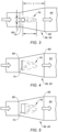
- An example of an acceptable bluff body 74 separation distance can be shown using the diagrammatic view shown in FIG. 3 .
- the bluff body 74 is cylindrical and has a diameter "d".
- the separation distance "L" between the center of the bluff body 74 and the entrance to the heat exchanger core 64 is in the range of fifteen to twenty-five bluff body diameters (L in the range of ⁇ 15d - 25d).
- L the separation distance of twenty bluff body diameters (20d) between the center of the bluff body 74 and the entrance to the heat exchanger core 64 will result in desirable dissipation of the flow vortices 76.
- the separation distance is chosen to ensure that the fluid vortices 76 substantially dissipate before the fluid enters the heat exchanger core 64 and specific values for the separation distance may vary.
- FIGS. 3-5 diagrammatically illustrate single bluff body 74 examples; e.g., FIG. 3 diagrammatically illustrates a circular shaped bluff body 74, FIG. 4 diagrammatically illustrates a bluff body 74 having a plate configuration, and FIG. 5 diagrammatically illustrates a bluff body 74 having a box-like configuration.
- the bluff bodies 74 diagrammatically shown in FIGS. 3-5 are provided as non-limiting examples of bluff body 74 configurations that may be used and the invention is not limited to these examples.
- FIGS. 3-5 diagrammatically illustrate single bluff body 74 examples; e.g., FIG. 3 diagrammatically illustrates a circular shaped bluff body 74, FIG. 4 diagrammatically illustrates a bluff body 74 having a plate configuration, and FIG. 5 diagrammatically illustrates a bluff body 74 having a box-like configuration.
- FIG. 6 and 7 diagrammatically illustrate non-limiting embodiments wherein more than one bluff body 74 may be used.
- FIG. 6 diagrammatically illustrates a single row of bluff bodies 74
- FIG. 7 diagrammatically illustrates two rows of bluff bodies 74.
- these multiple bluff body 74 configurations are provided to illustrate embodiments of the invention and the invention is not limited to these examples.
- embodiments are directed to a heat exchanger 54 that includes at least one inlet manifold 56, 60 and a heat exchanger core 64.
- the heat exchanger 54 includes a plurality of inlet manifolds (e.g., 56, 60).
- the above described bluff body 74 configuration may be implemented in one of the inlet manifolds, or in a plurality (but not all) of inlet manifolds, or in all the inlet manifolds.
- an exit manifold 58, 62 may be included in some embodiments of the heat exchanger 54.
- one or more of the exit manifolds may include a bluff body 74 configuration as described above.
- any one of these structures may describe the operations as a sequential process, many of the operations can be performed in parallel or concurrently.
- the order of the operations may be rearranged.
- a process may correspond to a method, a function, a procedure, a subroutine, a subprogram, etc.
Landscapes
- Engineering & Computer Science (AREA)
- Physics & Mathematics (AREA)
- Thermal Sciences (AREA)
- Mechanical Engineering (AREA)
- General Engineering & Computer Science (AREA)
- Fluid Mechanics (AREA)
- General Physics & Mathematics (AREA)
- Heat-Exchange Devices With Radiators And Conduit Assemblies (AREA)
Abstract
Description
- This invention relates to turbine engines in general, and to turbine engine components configured for heat transfer via a fluid flow in particular.
- Heat exchangers are commonly used in aircraft applications to transfer heat between two fluids ("working fluids") for heating or cooling purposes. An inlet manifold is typically used on the hot fluid entrance or the cold fluid entrance to the heat exchanger in order to facilitate onboarding of the working fluid to the exchanger. To prevent leakage, the manifolds are typically rigidly attached to the heat exchanger core. During typical operation, it is not uncommon for the heat exchanger core temperature to differ from the inlet manifold temperature. As the difference between the temperatures of the working fluids becomes larger, the thermal difference between the heat exchanger core and the inlet manifold typically also increases. In applications where thermally driven stresses are life limiting it is desirable to minimize this thermal gradient. Furthermore, a heat exchanger core is typically designed to maximize heat transfer between working fluids of differing temperatures while manifolds are typically designed to minimize pressure loss. This functional difference creates a thermally fast responding heat exchanger core and an inlet manifold geometry that transfers thermal energy slower resulting in high internal stresses within the inlet manifold, or the heat exchanger core, or both. It would be desirable to provide a heat exchanger that avoids or mitigates internal stresses.
- According to an aspect of the invention, a heat exchanger is provided that includes a heat exchanger core, an inlet manifold, and a turbulence generating structure. The inlet manifold is in fluid communication with the heat exchanger core. The inlet manifold has a fluid inlet and a fluid outlet. The turbulence generating structure is disposed adjacent to the fluid inlet of the inlet manifold and at a separation distance from the fluid outlet. The heat exchanger is configured with a fluid flow path through which a fluid flow enters the heat exchanger through the fluid inlet of the inlet manifold, encounters the turbulence generating structure and passes through the fluid outlet of the inlet manifold and into the heat exchanger core (e.g., the fluid flow path passes or extends sequentially through the fluid inlet, the turbulence generating structure (i.e. over or around the turbulence generating structure), through the fluid outlet, and into the heat exchanger core). The turbulence generating structure is configured to produce turbulence in the fluid flow.
- The separation distance may be long enough such that the fluid flow entering the heat exchanger core is substantially free of the turbulence resulting from the turbulence generating structure.
- In any of the aspects or embodiments described above and herein, the turbulence generating structure disposed adjacent to the fluid inlet of the inlet manifold may be a single structure.
- In any of the aspects or embodiments described above and herein, the turbulence generating structure may have a circular cross-section having a diameter, and the separation distance may be in the range of fifteen to twenty-five times the diameter of the turbulence generating structure.
- In any of the aspects or embodiments described above and herein, the separation distance may be about twenty times the diameter of the turbulence generating structure.
- In any of the aspects or embodiments described above and herein, the turbulence generating structure may be a vortex generator configured to produce fluid vortices in the fluid flow aft of the turbulence generating structure, and the turbulence in the fluid flow includes the fluid vortices.
- In any of the aspects or embodiments described above and herein, the turbulence generating structure configured to produce fluid vortices in the fluid flow aft of the vortex generator may be configured to form fluid vortices collectively as a Karman vortex street.
- In any of the aspects or embodiments described above and herein, the Kárman vortex street may have a length extending between the turbulence generating structure and the fluid outlet of the inlet manifold, and the length of the Kárman vortex street may be equal to or less than the separation distance.
- In any of the aspects or embodiments described above and herein, the heat exchanger may include an exit manifold, wherein the fluid flow path extends through the exit manifold.
- In any of the aspects or embodiments described above and herein, the heat exchanger may be configured as a counterflow heat exchanger (e.g., having fluid flow directions that are generally parallel and opposed to one another).
- In any of the aspects or embodiments described above and herein, the heat exchanger may be configured as a crossflow heat exchanger, wherein the fluid flow is a first fluid flow and the inlet manifold is a first inlet manifold, and the heat exchanger may be configured such the first fluid flow enters the heat exchanger through the fluid inlet of the first inlet manifold, encounters the turbulence generating structure and passes through the fluid outlet of the first inlet manifold and into the heat exchanger core, and the heat exchanger may have a second fluid path for a second fluid flow, and the second fluid path may be substantially orthogonal to the first fluid path.
- According to an aspect of the invention, a heat exchanger is provided that includes a heat exchanger core (e.g., the previously described heat exchanger core), a first inlet manifold (e.g., the previously described inlet manifold), a first turbulence generating structure (e.g., the previously described turbulence generating structure), and a second inlet manifold. The first inlet manifold is in fluid communication with the heat exchanger core, the first inlet manifold (FIM) having a FIM fluid inlet (e.g., the previously described fluid inlet) and a FIM fluid outlet (e.g., the previously described fluid outlet). The first turbulence generating structure is disposed adjacent to the FIM fluid inlet of the first inlet manifold, and a first separation distance from the FIM fluid outlet. The second inlet manifold is in fluid communication with the heat exchanger core. The second inlet manifold (SIM) has a SIM fluid inlet and a SIM fluid outlet. The heat exchanger is configured with a first fluid flow path (e.g., the previously described flow path) through which a first fluid flow enters the heat exchanger through the FIM fluid inlet, encounters the first turbulence generating structure and passes through the FIM fluid outlet, and into the heat exchanger core (e.g., the first fluid flow path passes or extends sequentially through the FIM fluid inlet, the first turbulence generating structure (i.e. over or around the first turbulence generating structure), through the FIM fluid outlet, and into the heat exchanger core, wherein the first turbulence generating structure is configured to produce turbulence in the first fluid flow.
- The first separation distance may be long enough such that the first fluid flow entering the heat exchanger core is substantially free of the turbulence resulting from the turbulence generating structure (e.g., the first separation distance may be selected such that the first fluid flow entering the heat exchanger core is substantially free of the turbulence resulting from the first turbulence generating structure).
- In any of the aspects or embodiments described above and herein, the heat exchanger may include a first exit manifold (FEM) (e.g., the previously described exit manifold) having a FEM fluid inlet and a FEM fluid outlet, wherein the first fluid flow path extends through the first exit manifold.
- In any of the aspects or embodiments described above and herein, a second turbulence generating structure may be provided. The second turbulence generating structure may be a vortex generator configured to produce fluid vortices in the first fluid flow downstream of the second turbulence generating structure.
- In any of the aspects or embodiments described above and herein, the heat exchanger may include a second turbulence generating structure disposed adjacent to the SIM fluid inlet and a second separation distance from the SIM fluid outlet, and the heat exchanger may be configured with a second fluid flow path through which a second fluid flow enters the heat exchanger through the SIM fluid inlet, encounters the second turbulence generating structure and passes through the SIM fluid outlet, and into the heat exchanger core (e.g., the second fluid flow path passes or extends sequentially through the SIM fluid inlet, the second turbulence generating structure (i.e. over or around the second turbulence generating structure), through the SIM fluid outlet, and into the heat exchanger core). The second turbulence generating structure may be configured to produce turbulence in the second fluid flow, and the second turbulence generating structure may be a vortex generator configured to produce fluid vortices in the second fluid flow downstream of the second turbulence generating structure.
- In any of the aspects or embodiments described above and herein, the second turbulence generating structure may be configured to form fluid vortices collectively as a second Kárman vortex street.
- In any of the aspects or embodiments described above and herein, the second Kárman vortex street may have a length extending between the second turbulence generating structure and the SIM fluid outlet, and the length of the second Kárman vortex street may be equal to or less than the second separation distance.
- In any of the aspects or embodiments described above and herein, the heat exchanger may include a second exit manifold (SEM) having a SEM fluid inlet and a SEM fluid outlet, and the second fluid flow path may extend through the second exit manifold.
- The foregoing features and elements may be combined in various combinations without exclusivity, unless expressly indicated otherwise. For example, aspects and/or embodiments of the present invention may include any one or more of the individual features or elements disclosed above and/or below alone or in any combination thereof. These features and elements as well as the operation thereof will become more apparent in light of the following description and the accompanying drawings. It should be understood, however, the following description and drawings are intended to be exemplary in nature and non-limiting.
-
-
FIG. 1 is a diagrammatic sectional view of a gas turbine engine. -
FIG. 2 is a diagrammatic view of a heat exchanger. -
FIG. 3 is a diagrammatic view of an inlet manifold example. -
FIG. 4 is a diagrammatic view of an inlet manifold example. -
FIG. 5 is a diagrammatic view of an inlet manifold example. -
FIG. 6 is a diagrammatic view of an inlet manifold example. -
FIG. 7 is a diagrammatic view of an inlet manifold example. -
FIG. 1 shows a partially sectioned diagrammatic view of a gearedgas turbine engine 20. Thegas turbine engine 20 extends along anaxial centerline 22 between anupstream airflow inlet 24 and adownstream airflow exhaust 26. Thegas turbine engine 20 includes afan section 28, acompressor section 30, acombustor section 32, and aturbine section 34. Thecombustor section 32 includes anannular combustor 36. The compressor section includes a low-pressure compressor (LPC) 38 and a high-pressure compressor (HPC) 40. Theturbine section 34 includes a high-pressure turbine (HPT) 42 and a low-pressure turbine (LPT) 44. In the embodiment shown inFIG. 1 , the engine sections are arranged sequentially along thecenterline 22 within an engine housing. Thefan section 28 is connected to a gearedarchitecture 46, for example, through afan shaft 48. The gearedarchitecture 46 and theLPC 38 are connected to and driven by theLPT 44 through a low-speed shaft 50. TheHPC 40 is connected to and driven by theHPT 42 through a high-speed shaft 52. The terms "forward", "leading", "aft, "trailing" are used herein to indicate the relative position of a component or surface. As air passes through theengine 20, a "leading edge" of a stator vane or rotor blade encounters the air before the "trailing edge" of the same. In a conventional axial engine such as that shown inFIG. 1 , thefan section 28 is "forward" of thecompressor section 30 and theturbine section 34 is "aft" of thecompressor section 30. The terms "inner radial" and "outer radial" refer to relative radial positions from theengine centerline 22. An inner radial component or path is disposed radially closer to theengine centerline 22 than an outer radial component or path. The gas turbine engine diagrammatically shown inFIG. 1 is an example provided to facilitate the description herein. The present invention is not limited to any particular gas turbine engine configuration, including the two-spool engine configuration shown, and may be utilized with single spool gas turbine engines as well as three spool gas turbine engines and the like. - During operation, air enters the
gas turbine engine 20 through theairflow inlet 24 and may be directed through thefan section 28 and into a core gas path. The gas traveling along the core gas path is directed through theengine sections gas turbine engine 20 through theairflow exhaust 26 to provide forward engine thrust. Within thecombustor section 32, fuel is injected into acombustor 36 and mixed with compressed air. This fuel-air mixture is ignited to power thegas turbine engine 20. The non-combusted air and combustion products produced in thecombustor 36 pass to theturbine section 34 where they power theturbine section 34. - An aircraft propulsion system that includes a turbine engine often includes one or more heat exchangers and different heat exchangers may be utilized in different applications. Embodiments of the invention include a heat exchanger having at least one fluid inlet manifold and a heat exchanger core, and may include at least one fluid exit manifold. The heat exchanger core may have a crossflow or counterflow configuration for use with a first working fluid and a second working fluid, wherein the first and second working fluids are at different temperatures; e.g., the first working fluid is at a temperature higher than the second working fluid or vice versa. The invention is not limited to a heat exchanger core in a crossflow or counterflow configuration. In other embodiments, aspects of invention may be utilized in other structures wherein a working fluid (e.g., a hot fluid that is used to heat, or a cool fluid that is used to cool) is used to affect heat transfer with an engine component of the like. Examples of such components with which the invention may be used include vane airfoils, blade airfoils, blade outer air seals (BOAS), and the like. To facilitate the description herein after, the term "heat exchanger" as used hereinafter is intended to include crossflow type heat exchangers as well as other components through which a working fluid is passed for purposes of heat transfer between the working fluid and the structure unless otherwise indicated. To be clear, the term "fluid" here is intended to include both gaseous fluids and liquid fluids.
- In those embodiments wherein the heat exchanger core has a crossflow configuration for use with a first working fluid and a second working fluid, the first and second working fluids are at different temperatures; e.g., the first working fluid is at a temperature higher than the second working fluid or vice versa. The first and second fluid flows cross one another (e.g., fluid flow directions that are generally orthogonal to one another) but are maintained fluidly isolated from one another. At least one of the working fluids passing through the heat exchanger 54 (e.g., see
FIG. 2 ) may follow a fluid path through an inlet manifold, a heat exchanger core, and an exit manifold; e.g., a first fluid (FF) path through an FF inlet manifold, an FF portion of the heat exchanger core, and an FF exit manifold. In some embodiments, each working fluid may follow a fluid path through a respective inlet manifold, heat exchanger core, and exit manifold; e.g., a first fluid (FF) path through an FF inlet manifold, an FF portion of the heat exchanger core, and an FF exit manifold, and a second fluid (SF) path through a SF inlet manifold, a SF portion of the heat exchanger core, and a SF exit manifold. To facilitate the description herein after, embodiments of the invention will be described as having a fluid path that passes through an inlet manifold, a heat exchanger core, and an exit manifold. The fluid flow path characteristics described hereinafter may be applicable to only the first or second fluid path, or to both the first and second fluid paths. -
FIG. 2 diagrammatically illustrates aheat exchanger 54 that includes afirst inlet manifold 56, afirst exit manifold 58, a second inlet manifold 60, asecond exit manifold 62, and aheat exchanger core 64. The inlet manifolds 56, 60 include at least onefluid inlet 66 and afluid outlet 68 that is configured to distribute working fluid into theheat exchanger core 64. The exit manifolds 58, 62 include afluid inlet 70 configured to collect working fluid from theheat exchanger core 64 and at least onefluid exit 72. The inlet and exit manifolds 56, 58, 60, 62 may be rigidly attached to theheat exchanger core 64 or structure housing or supporting theheat exchanger core 64. - A first working fluid following a first fluid flow path through the
heat exchanger 54 enters thefirst inlet manifold 56, passes through theheat exchanger core 64, and enters and exits thefirst exit manifold 58. A second working fluid following a second fluid flow path through theheat exchanger 54 enters the second inlet manifold 60, passes through theheat exchanger core 64, and enters and exits thesecond exit manifold 62. - As indicated above, during operation it is not uncommon for the
heat exchanger core 64 temperature to differ from the inlet manifold temperature due to differences between the working fluids engaged with theheat exchanger 54. In particular, it is not uncommon for theheat exchanger core 64 temperature to vary as a function of time from the inlet manifold temperature. The changes in temperature will likely cause the materials of the heat exchanger 54 (each with their own heat transfer coefficient) to experience thermal expansion or contraction (collectively referred to herein as "thermal growth"). Moreover, the rate of thermal growth of the respective components is likely to differ. Because the inlet and exit manifolds 56, 59, 60, 62 are typically rigidly attached to one another, the differences in thermal growth and/or rate of thermal growth can induce undesirable stress in therespective heat exchanger 54 components. - To mitigate or avoid the undesirable stress in the
respective heat exchanger 54 components, structure 74 (e.g., seeFIGS. 3-7 ) is included within at least one of the inlet manifolds 56, 60 that is configured to produce turbulent flow within therespective inlet manifold 56, 60 to improve heat transfer between the working fluid passing through theinlet manifold 56, 60 and theinlet manifold 56, 60 itself. The improvement in heat transfer is understood to, in turn, decrease any differences in thermal growth and/or rate of thermal growth between theinlet manifold 56, 60 and theheat exchanger core 64 by, for example, adding vortex generator features that passively control manifold temperatures. - The diffusive characteristics of turbulent flow enhance heat transfer in general. In some embodiments (e.g., see
FIGS. 3-7 ), thestructure 74 within theinlet manifold 56, 60 that is configured to produce turbulent flow and may be more specifically configured to produce turbulent flow that inhibits the boundary layer formation and/or growth oninlet manifold 56, 60 surfaces. Boundary layers impede heat transfer between the working fluid and the surface on which the boundary layer is formed. Turbulent flow produced by embodiments of the structure inhibits boundary layer development and consequently inhibits any thermally insulative effect that may be associated with the boundary layer. - In some embodiments, the
structure 74 within theinlet manifold 56, 60 that is configured to produce turbulent flow is more specifically configured to act as a vortex generator, one that sheds fluid vortices 76 (e.g., seeFIGS. 3-5 ) downstream of thestructure 74 disposed within theinlet manifold 56, 60. The vortex shedding is an oscillating flow that occurs when the working fluid flows passes a bluff body (e.g.,structure 74, as opposed to a streamlined body) at certain velocities. The geometry of the bluff body 74 (e.g., size and shape) may be chosen based on characteristics of the working fluid (e.g., viscosity, density, or the like, or combinations thereof), the velocity of the fluid passing thebluff body 74, the geometry of the fluid flow path withininlet manifold 56, 60, and the like. Thevortices 76 are created at the flow-wise back of thebluff body 74 and detach periodically from either side of thebluff body 74 forming a Kárman vortex street. The vortices forming the Kárman vortex street will dissipate over a distance. - Embodiments of the
inlet manifold 56, 60 may be configured with thebluff body 74 disposed proximate to thefluid inlet 66 of theinlet manifold 56, 60. Thebluff body 74 may be disposed centrally relative to thefluid inlet 66 of theinlet manifold 56, 60, but is not required to be located centrally. - The
bluff body 74 is spaced apart from theheat exchanger core 64 by a separation distance "L". The separation distance is chosen at least in part on a distance that is sufficient for thefluid vortices 76 to substantially dissipate before the fluid enters theheat exchanger core 64. The separation distance typically is chosen so that thefluid vortices 76 entirely (or almost entirely) dissipate before the fluid enters theheat exchanger core 64; i.e., thevortices 76 forming the Kárman vortex street will dissipate over a distance equal to or shorter than the separation distance. An example of anacceptable bluff body 74 separation distance can be shown using the diagrammatic view shown inFIG. 3 . In this example, thebluff body 74 is cylindrical and has a diameter "d". The separation distance "L" between the center of thebluff body 74 and the entrance to theheat exchanger core 64 is in the range of fifteen to twenty-five bluff body diameters (L in the range of ≈ 15d - 25d). For most applications (e.g., fluid type, fluid velocity, and the like of a particular application), a separation distance of twenty bluff body diameters (20d) between the center of thebluff body 74 and the entrance to theheat exchanger core 64 will result in desirable dissipation of theflow vortices 76. As stated above, the separation distance is chosen to ensure that thefluid vortices 76 substantially dissipate before the fluid enters theheat exchanger core 64 and specific values for the separation distance may vary. - As stated above, the geometry of the
bluff body 74 may be chosen based on several different parameters. In some embodiments, asingle bluff body 74 may be utilized.FIGS. 3-5 diagrammatically illustratesingle bluff body 74 examples; e.g.,FIG. 3 diagrammatically illustrates a circular shapedbluff body 74,FIG. 4 diagrammatically illustrates abluff body 74 having a plate configuration, andFIG. 5 diagrammatically illustrates abluff body 74 having a box-like configuration. Thebluff bodies 74 diagrammatically shown inFIGS. 3-5 are provided as non-limiting examples ofbluff body 74 configurations that may be used and the invention is not limited to these examples.FIGS. 6 and 7 diagrammatically illustrate non-limiting embodiments wherein more than onebluff body 74 may be used.FIG. 6 diagrammatically illustrates a single row ofbluff bodies 74 andFIG. 7 diagrammatically illustrates two rows ofbluff bodies 74. Here again, these multiplebluff body 74 configurations are provided to illustrate embodiments of the invention and the invention is not limited to these examples. - As indicated above, embodiments are directed to a
heat exchanger 54 that includes at least oneinlet manifold 56, 60 and aheat exchanger core 64. In some embodiments, theheat exchanger 54 includes a plurality of inlet manifolds (e.g., 56, 60). The above describedbluff body 74 configuration may be implemented in one of the inlet manifolds, or in a plurality (but not all) of inlet manifolds, or in all the inlet manifolds. Also as indicated above, anexit manifold heat exchanger 54. In those embodiments, one or more of the exit manifolds may include abluff body 74 configuration as described above. - While the principles of the invention have been described above in connection with specific apparatuses and methods, it is to be clearly understood that this description is made only by way of example and not as limitation on the scope of the invention. Specific details are given in the above description to provide a thorough understanding of the embodiments. However, it is understood that the embodiments may be practiced without these specific details.
- It is noted that the embodiments may be described as a process which is depicted as a flowchart, a flow diagram, a block diagram, etc. Although any one of these structures may describe the operations as a sequential process, many of the operations can be performed in parallel or concurrently. In addition, the order of the operations may be rearranged. A process may correspond to a method, a function, a procedure, a subroutine, a subprogram, etc.
- The singular forms "a," "an," and "the" refer to one or more than one, unless the context clearly dictates otherwise. For example, the term "comprising a specimen" includes single or plural specimens and is considered equivalent to the phrase "comprising at least one specimen." The term "or" refers to a single element of stated alternative elements or a combination of two or more elements unless the context clearly indicates otherwise. As used herein, "comprises" means "includes." Thus, "comprising A or B," means "including A or B, or A and B," without excluding additional elements.
- It is noted that various connections are set forth between elements in the present description and drawings (the contents of which are included in this disclosure by way of reference). It is noted that these connections are general and, unless specified otherwise, may be direct or indirect and that this specification is not intended to be limiting in this respect. Any reference to attached, fixed, connected or the like may include permanent, removable, temporary, partial, full and/or any other possible attachment option.
- No element, component, or method step in the present disclosure is intended to be dedicated to the public regardless of whether the element, component, or method step is explicitly recited in the claims. As used herein, the terms "comprise", "comprising", or any other variation thereof, are intended to cover a non-exclusive inclusion, such that a process, method, article, or apparatus that comprises a list of elements does not include only those elements but may include other elements not expressly listed or inherent to such process, method, article, or apparatus.
- While various inventive aspects, concepts and features of the invention may be described and illustrated herein as embodied in combination in the exemplary embodiments, these various aspects, concepts, and features may be used in many alternative embodiments, either individually or in various combinations and sub-combinations thereof. Unless expressly excluded herein all such combinations and sub-combinations are intended to be within the scope of the present application. Still further, while various alternative embodiments as to the various aspects, concepts, and features of the invention--such as alternative materials, structures, configurations, methods, devices, and components, and so on--may be described herein, such descriptions are not intended to be a complete or exhaustive list of available alternative embodiments, whether presently known or later developed. Those skilled in the art may readily adopt one or more of the inventive aspects, concepts, or features into additional embodiments and uses within the scope of the present application even if such embodiments are not expressly disclosed herein. For example, in the exemplary embodiments described above within the Detailed Description portion of the present specification, elements may be described as individual units and shown as independent of one another to facilitate the description. In alternative embodiments, such elements may be configured as combined elements. It is further noted that various method or process steps for embodiments of the present invention are described herein. The description may present method and/or process steps as a particular sequence. However, to the extent that the method or process does not rely on the particular order of steps set forth herein, the method or process should not be limited to the particular sequence of steps described. As one of ordinary skill in the art would appreciate, other sequences of steps may be possible. Therefore, the particular order of the steps set forth in the description should not be construed as a limitation.
Claims (15)
- A heat exchanger (54) comprising:a heat exchanger core (64);an inlet manifold (56) in fluid communication with the heat exchanger core (64), the inlet manifold (56) having a fluid inlet (66) and a fluid outlet (68); anda turbulence generating structure (74) disposed adjacent to the fluid inlet (66) of the inlet manifold (56) and at a separation distance (L) from the fluid outlet (68), wherein:the heat exchanger (54) is configured with a fluid flow path through which a fluid flow enters the heat exchanger (54) through the fluid inlet (66) of the inlet manifold (56), encounters the turbulence generating structure (74) and passes through the fluid outlet (68) of the inlet manifold (56) and into the heat exchanger core (64); andthe turbulence generating structure (74) is configured to produce turbulence in the fluid flow; andthe separation distance (L) is long enough such that the fluid flow entering the heat exchanger core (64) is substantially free of the turbulence resulting from the turbulence generating structure (74).
- The heat exchanger (54) of claim 1, wherein the turbulence generating structure (74) is a single structure (74).
- The heat exchanger (54) of claim 1 or 2, wherein the turbulence generating structure (74) has a circular cross-section having a diameter (d), and the separation distance (L) is in the range of fifteen to twenty-five times the diameter (d) of the turbulence generating structure (74).
- The heat exchanger (54) of claim 3, wherein the separation distance is about twenty times the diameter of the turbulence generating structure (74).
- The heat exchanger (54) of any preceding claim, wherein the turbulence generating structure (74) is a vortex generator configured to produce fluid vortices (76) in the fluid flow aft of the turbulence generating structure (74), and the turbulence in the fluid flow includes the fluid vortices (76).
- The heat exchanger (54) of claim 5, wherein the turbulence generating structure (74) is configured to form said fluid vortices (76) collectively as a Kárman vortex street.
- The heat exchanger (54) of claim 6, wherein the Kárman vortex street has a length extending between the turbulence generating structure (74) and the fluid outlet (68) of the inlet manifold (56), and the length of the Kárman vortex street is equal to or less than the separation distance (L).
- The heat exchanger (54) of any preceding claim, comprising an exit manifold (58), wherein the fluid flow path extends through the exit manifold (58).
- The heat exchanger (54) of any preceding claim, wherein:the heat exchanger (54) is configured as a crossflow heat exchanger (54);the fluid flow path is a first fluid flow path and the inlet manifold (56) is a first inlet manifold (56); andthe heat exchanger (54) comprises a second fluid flow path for a second fluid flow, the second fluid flow path substantially orthogonal to the first fluid flow path.
- The heat exchanger (54) of any of claims 1 to 8, wherein:the inlet manifold (56) is a first inlet manifold (FIM) (56);the fluid inlet (66) is a FIM fluid inlet (66);the fluid outlet (68) is a FIM fluid outlet (68);the turbulence generating structure (74) is a first turbulence generating structure (74);the fluid flow path is a first fluid flow path; andthe heat exchanger (54) comprises a second inlet manifold (SIM) (60) in fluid communication with the heat exchanger core (64), the SIM (60) having a SIM fluid inlet (66) and a SIM fluid outlet (68).
- The heat exchanger (54) of claim 10, comprising:
a first exit manifold (58) (FEM) having a FEM fluid inlet (70) and a FEM fluid outlet (72), wherein the first fluid flow path extends through the first exit manifold (58). - The heat exchanger (54) of claim 10 or 11, comprising a second turbulence generating structure (74) disposed adjacent to the SIM fluid inlet (66) and a second separation distance (L) from the SIM fluid outlet (68), wherein:the heat exchanger (54) is configured with a second fluid flow path through which a second fluid flow enters the heat exchanger (54) through the SIM fluid inlet (66), encounters the second turbulence generating structure (74) and passes through the SIM fluid outlet (68) and into the heat exchanger core (64), wherein the second turbulence generating structure (74) is configured to produce turbulence in the second fluid flow; andthe second turbulence generating structure (74) is a vortex generator configured to produce fluid vortices (76) in the second fluid flow downstream of the second turbulence generating structure (74).
- The heat exchanger (54) of claim 12, wherein the second turbulence generating structure (74) is configured to form said fluid vortices (76) collectively as a second Kárman vortex street.
- The heat exchanger (54) of claim 13, wherein the second Kárman vortex street has a length extending between the second turbulence generating structure (74) and the SIM fluid outlet (68), and the length of the second Kárman vortex street is equal to or less than the second separation distance.
- The heat exchanger (54) of any of claims 12 to 14, comprising a second exit manifold (62) (SEM) having a SEM fluid inlet (70) and a SEM fluid outlet (72), wherein the second fluid flow path extends through the second exit manifold (62).
Applications Claiming Priority (1)
| Application Number | Priority Date | Filing Date | Title |
|---|---|---|---|
| US18/215,761 US20250003704A1 (en) | 2023-06-28 | 2023-06-28 | Heat Exchanger with Enhanced Heat Transfer Manifold |
Publications (2)
| Publication Number | Publication Date |
|---|---|
| EP4484881A1 true EP4484881A1 (en) | 2025-01-01 |
| EP4484881B1 EP4484881B1 (en) | 2026-02-11 |
Family
ID=91738492
Family Applications (1)
| Application Number | Title | Priority Date | Filing Date |
|---|---|---|---|
| EP24185546.9A Active EP4484881B1 (en) | 2023-06-28 | 2024-06-28 | Heat exchanger with enhanced heat transfer manifold |
Country Status (2)
| Country | Link |
|---|---|
| US (1) | US20250003704A1 (en) |
| EP (1) | EP4484881B1 (en) |
Citations (5)
| Publication number | Priority date | Publication date | Assignee | Title |
|---|---|---|---|---|
| EP1293742A2 (en) * | 2001-09-12 | 2003-03-19 | Behr GmbH & Co. | Exhaust gas heat exchanger |
| US20180106561A1 (en) * | 2016-10-13 | 2018-04-19 | Hs Marston Aerospace Limited | Heat exchanger |
| US20190390924A1 (en) * | 2018-06-21 | 2019-12-26 | United Technologies Corporation | Apparatus for conditioning heat exchanger flow |
| KR20220020526A (en) * | 2020-08-12 | 2022-02-21 | 주식회사 엘지화학 | Heat exchanger equipped with fluid flow distributor |
| EP4015976A1 (en) * | 2020-12-15 | 2022-06-22 | Valeo Autosystemy SP. Z.O.O. | Heat exchanger |
-
2023
- 2023-06-28 US US18/215,761 patent/US20250003704A1/en active Pending
-
2024
- 2024-06-28 EP EP24185546.9A patent/EP4484881B1/en active Active
Patent Citations (5)
| Publication number | Priority date | Publication date | Assignee | Title |
|---|---|---|---|---|
| EP1293742A2 (en) * | 2001-09-12 | 2003-03-19 | Behr GmbH & Co. | Exhaust gas heat exchanger |
| US20180106561A1 (en) * | 2016-10-13 | 2018-04-19 | Hs Marston Aerospace Limited | Heat exchanger |
| US20190390924A1 (en) * | 2018-06-21 | 2019-12-26 | United Technologies Corporation | Apparatus for conditioning heat exchanger flow |
| KR20220020526A (en) * | 2020-08-12 | 2022-02-21 | 주식회사 엘지화학 | Heat exchanger equipped with fluid flow distributor |
| EP4015976A1 (en) * | 2020-12-15 | 2022-06-22 | Valeo Autosystemy SP. Z.O.O. | Heat exchanger |
Also Published As
| Publication number | Publication date |
|---|---|
| US20250003704A1 (en) | 2025-01-02 |
| EP4484881B1 (en) | 2026-02-11 |
Similar Documents
| Publication | Publication Date | Title |
|---|---|---|
| US11421598B2 (en) | Staggered heat exchanger array with side curtains | |
| US10344674B2 (en) | Heat exchanger for embedded engine applications: transduct segments | |
| US10126062B2 (en) | Heat exchanger for embedded engine applications | |
| EP2578803B1 (en) | Methods and systems for use in regulating a temperature of components | |
| US11293304B2 (en) | Gas turbine engines including channel-cooled hooks for retaining a part relative to an engine casing structure | |
| EP3190272A1 (en) | Methos of cooling a fluid using an annular heat exchanger | |
| EP3190285A1 (en) | Heat exchanger for embedded engine applications: curvilinear plate | |
| US10753608B2 (en) | Turbine engine multi-walled structure with internal cooling element(s) | |
| EP1923538A2 (en) | Turbine with tip clearance control by transpiration | |
| US10823067B2 (en) | System for a surface cooler with OGV oriented fin angles | |
| EP3075964A1 (en) | System for cooling a turbine engine | |
| US11773729B2 (en) | Component for a gas turbine engine with a film hole | |
| EP3342978B1 (en) | Integrated squealer pocket tip and tip shelf with hybrid and tip flag core | |
| EP3214274B1 (en) | Encapsulated cooling for turbine shrouds | |
| US20160047271A1 (en) | Ducting platform cover plate | |
| EP4484881B1 (en) | Heat exchanger with enhanced heat transfer manifold | |
| EP4477858A2 (en) | Turbine engine compressor intercooler | |
| US10024271B2 (en) | Methods and systems for cooling airflow | |
| US10655496B2 (en) | Platform flow turning elements for gas turbine engine components |
Legal Events
| Date | Code | Title | Description |
|---|---|---|---|
| PUAI | Public reference made under article 153(3) epc to a published international application that has entered the european phase |
Free format text: ORIGINAL CODE: 0009012 |
|
| STAA | Information on the status of an ep patent application or granted ep patent |
Free format text: STATUS: THE APPLICATION HAS BEEN PUBLISHED |
|
| AK | Designated contracting states |
Kind code of ref document: A1 Designated state(s): AL AT BE BG CH CY CZ DE DK EE ES FI FR GB GR HR HU IE IS IT LI LT LU LV MC ME MK MT NL NO PL PT RO RS SE SI SK SM TR |
|
| STAA | Information on the status of an ep patent application or granted ep patent |
Free format text: STATUS: REQUEST FOR EXAMINATION WAS MADE |
|
| 17P | Request for examination filed |
Effective date: 20250701 |
|
| GRAP | Despatch of communication of intention to grant a patent |
Free format text: ORIGINAL CODE: EPIDOSNIGR1 |
|
| STAA | Information on the status of an ep patent application or granted ep patent |
Free format text: STATUS: GRANT OF PATENT IS INTENDED |
|
| RIC1 | Information provided on ipc code assigned before grant |
Ipc: F28F 13/12 20060101AFI20250813BHEP |
|
| INTG | Intention to grant announced |
Effective date: 20250903 |
|
| GRAS | Grant fee paid |
Free format text: ORIGINAL CODE: EPIDOSNIGR3 |
|
| GRAA | (expected) grant |
Free format text: ORIGINAL CODE: 0009210 |
|
| STAA | Information on the status of an ep patent application or granted ep patent |
Free format text: STATUS: THE PATENT HAS BEEN GRANTED |
|
| AK | Designated contracting states |
Kind code of ref document: B1 Designated state(s): AL AT BE BG CH CY CZ DE DK EE ES FI FR GB GR HR HU IE IS IT LI LT LU LV MC ME MK MT NL NO PL PT RO RS SE SI SK SM TR |
|
| REG | Reference to a national code |
Ref country code: CH Ref legal event code: F10 Free format text: ST27 STATUS EVENT CODE: U-0-0-F10-F00 (AS PROVIDED BY THE NATIONAL OFFICE) Effective date: 20260211 Ref country code: GB Ref legal event code: FG4D |
|
| REG | Reference to a national code |
Ref country code: DE Ref legal event code: R096 Ref document number: 602024002489 Country of ref document: DE |
|
| REG | Reference to a national code |
Ref country code: IE Ref legal event code: FG4D |