EP4484860A1 - System and method for detection and correction of reverse flow in an ejector refrigeration circuit - Google Patents
System and method for detection and correction of reverse flow in an ejector refrigeration circuit Download PDFInfo
- Publication number
- EP4484860A1 EP4484860A1 EP24185566.7A EP24185566A EP4484860A1 EP 4484860 A1 EP4484860 A1 EP 4484860A1 EP 24185566 A EP24185566 A EP 24185566A EP 4484860 A1 EP4484860 A1 EP 4484860A1
- Authority
- EP
- European Patent Office
- Prior art keywords
- ejector
- ejectors
- refrigerant
- superheat
- flow
- Prior art date
- Legal status (The legal status is an assumption and is not a legal conclusion. Google has not performed a legal analysis and makes no representation as to the accuracy of the status listed.)
- Pending
Links
Images


Classifications
-
- F—MECHANICAL ENGINEERING; LIGHTING; HEATING; WEAPONS; BLASTING
- F25—REFRIGERATION OR COOLING; COMBINED HEATING AND REFRIGERATION SYSTEMS; HEAT PUMP SYSTEMS; MANUFACTURE OR STORAGE OF ICE; LIQUEFACTION SOLIDIFICATION OF GASES
- F25B—REFRIGERATION MACHINES, PLANTS OR SYSTEMS; COMBINED HEATING AND REFRIGERATION SYSTEMS; HEAT PUMP SYSTEMS
- F25B49/00—Arrangement or mounting of control or safety devices
- F25B49/02—Arrangement or mounting of control or safety devices for compression type machines, plants or systems
-
- F—MECHANICAL ENGINEERING; LIGHTING; HEATING; WEAPONS; BLASTING
- F04—POSITIVE - DISPLACEMENT MACHINES FOR LIQUIDS; PUMPS FOR LIQUIDS OR ELASTIC FLUIDS
- F04F—PUMPING OF FLUID BY DIRECT CONTACT OF ANOTHER FLUID OR BY USING INERTIA OF FLUID TO BE PUMPED; SIPHONS
- F04F5/00—Jet pumps, i.e. devices in which flow is induced by pressure drop caused by velocity of another fluid flow
- F04F5/14—Jet pumps, i.e. devices in which flow is induced by pressure drop caused by velocity of another fluid flow the inducing fluid being elastic fluid
- F04F5/16—Jet pumps, i.e. devices in which flow is induced by pressure drop caused by velocity of another fluid flow the inducing fluid being elastic fluid displacing elastic fluids
- F04F5/18—Jet pumps, i.e. devices in which flow is induced by pressure drop caused by velocity of another fluid flow the inducing fluid being elastic fluid displacing elastic fluids for compressing
-
- F—MECHANICAL ENGINEERING; LIGHTING; HEATING; WEAPONS; BLASTING
- F25—REFRIGERATION OR COOLING; COMBINED HEATING AND REFRIGERATION SYSTEMS; HEAT PUMP SYSTEMS; MANUFACTURE OR STORAGE OF ICE; LIQUEFACTION SOLIDIFICATION OF GASES
- F25B—REFRIGERATION MACHINES, PLANTS OR SYSTEMS; COMBINED HEATING AND REFRIGERATION SYSTEMS; HEAT PUMP SYSTEMS
- F25B9/00—Compression machines, plants or systems, in which the refrigerant is air or other gas of low boiling point
- F25B9/08—Compression machines, plants or systems, in which the refrigerant is air or other gas of low boiling point using ejectors
-
- F—MECHANICAL ENGINEERING; LIGHTING; HEATING; WEAPONS; BLASTING
- F04—POSITIVE - DISPLACEMENT MACHINES FOR LIQUIDS; PUMPS FOR LIQUIDS OR ELASTIC FLUIDS
- F04F—PUMPING OF FLUID BY DIRECT CONTACT OF ANOTHER FLUID OR BY USING INERTIA OF FLUID TO BE PUMPED; SIPHONS
- F04F5/00—Jet pumps, i.e. devices in which flow is induced by pressure drop caused by velocity of another fluid flow
- F04F5/44—Component parts, details, or accessories not provided for in, or of interest apart from, groups F04F5/02 - F04F5/42
- F04F5/46—Arrangements of nozzles
-
- F—MECHANICAL ENGINEERING; LIGHTING; HEATING; WEAPONS; BLASTING
- F04—POSITIVE - DISPLACEMENT MACHINES FOR LIQUIDS; PUMPS FOR LIQUIDS OR ELASTIC FLUIDS
- F04F—PUMPING OF FLUID BY DIRECT CONTACT OF ANOTHER FLUID OR BY USING INERTIA OF FLUID TO BE PUMPED; SIPHONS
- F04F5/00—Jet pumps, i.e. devices in which flow is induced by pressure drop caused by velocity of another fluid flow
- F04F5/44—Component parts, details, or accessories not provided for in, or of interest apart from, groups F04F5/02 - F04F5/42
- F04F5/48—Control
-
- F—MECHANICAL ENGINEERING; LIGHTING; HEATING; WEAPONS; BLASTING
- F04—POSITIVE - DISPLACEMENT MACHINES FOR LIQUIDS; PUMPS FOR LIQUIDS OR ELASTIC FLUIDS
- F04F—PUMPING OF FLUID BY DIRECT CONTACT OF ANOTHER FLUID OR BY USING INERTIA OF FLUID TO BE PUMPED; SIPHONS
- F04F5/00—Jet pumps, i.e. devices in which flow is induced by pressure drop caused by velocity of another fluid flow
- F04F5/44—Component parts, details, or accessories not provided for in, or of interest apart from, groups F04F5/02 - F04F5/42
- F04F5/48—Control
- F04F5/50—Control of compressing pumps
-
- F—MECHANICAL ENGINEERING; LIGHTING; HEATING; WEAPONS; BLASTING
- F25—REFRIGERATION OR COOLING; COMBINED HEATING AND REFRIGERATION SYSTEMS; HEAT PUMP SYSTEMS; MANUFACTURE OR STORAGE OF ICE; LIQUEFACTION SOLIDIFICATION OF GASES
- F25B—REFRIGERATION MACHINES, PLANTS OR SYSTEMS; COMBINED HEATING AND REFRIGERATION SYSTEMS; HEAT PUMP SYSTEMS
- F25B2341/00—Details of ejectors not being used as compression device; Details of flow restrictors or expansion valves
- F25B2341/001—Ejectors not being used as compression device
- F25B2341/0012—Ejectors with the cooled primary flow at high pressure
-
- F—MECHANICAL ENGINEERING; LIGHTING; HEATING; WEAPONS; BLASTING
- F25—REFRIGERATION OR COOLING; COMBINED HEATING AND REFRIGERATION SYSTEMS; HEAT PUMP SYSTEMS; MANUFACTURE OR STORAGE OF ICE; LIQUEFACTION SOLIDIFICATION OF GASES
- F25B—REFRIGERATION MACHINES, PLANTS OR SYSTEMS; COMBINED HEATING AND REFRIGERATION SYSTEMS; HEAT PUMP SYSTEMS
- F25B2341/00—Details of ejectors not being used as compression device; Details of flow restrictors or expansion valves
- F25B2341/001—Ejectors not being used as compression device
- F25B2341/0013—Ejector control arrangements
-
- F—MECHANICAL ENGINEERING; LIGHTING; HEATING; WEAPONS; BLASTING
- F25—REFRIGERATION OR COOLING; COMBINED HEATING AND REFRIGERATION SYSTEMS; HEAT PUMP SYSTEMS; MANUFACTURE OR STORAGE OF ICE; LIQUEFACTION SOLIDIFICATION OF GASES
- F25B—REFRIGERATION MACHINES, PLANTS OR SYSTEMS; COMBINED HEATING AND REFRIGERATION SYSTEMS; HEAT PUMP SYSTEMS
- F25B2341/00—Details of ejectors not being used as compression device; Details of flow restrictors or expansion valves
- F25B2341/001—Ejectors not being used as compression device
- F25B2341/0015—Ejectors not being used as compression device using two or more ejectors
-
- F—MECHANICAL ENGINEERING; LIGHTING; HEATING; WEAPONS; BLASTING
- F25—REFRIGERATION OR COOLING; COMBINED HEATING AND REFRIGERATION SYSTEMS; HEAT PUMP SYSTEMS; MANUFACTURE OR STORAGE OF ICE; LIQUEFACTION SOLIDIFICATION OF GASES
- F25B—REFRIGERATION MACHINES, PLANTS OR SYSTEMS; COMBINED HEATING AND REFRIGERATION SYSTEMS; HEAT PUMP SYSTEMS
- F25B2400/00—Component parts or details not otherwise provided for in this subclass
- F25B2400/23—Separators
-
- F—MECHANICAL ENGINEERING; LIGHTING; HEATING; WEAPONS; BLASTING
- F25—REFRIGERATION OR COOLING; COMBINED HEATING AND REFRIGERATION SYSTEMS; HEAT PUMP SYSTEMS; MANUFACTURE OR STORAGE OF ICE; LIQUEFACTION SOLIDIFICATION OF GASES
- F25B—REFRIGERATION MACHINES, PLANTS OR SYSTEMS; COMBINED HEATING AND REFRIGERATION SYSTEMS; HEAT PUMP SYSTEMS
- F25B2600/00—Control issues
- F25B2600/25—Control of valves
- F25B2600/2515—Flow valves
-
- F—MECHANICAL ENGINEERING; LIGHTING; HEATING; WEAPONS; BLASTING
- F25—REFRIGERATION OR COOLING; COMBINED HEATING AND REFRIGERATION SYSTEMS; HEAT PUMP SYSTEMS; MANUFACTURE OR STORAGE OF ICE; LIQUEFACTION SOLIDIFICATION OF GASES
- F25B—REFRIGERATION MACHINES, PLANTS OR SYSTEMS; COMBINED HEATING AND REFRIGERATION SYSTEMS; HEAT PUMP SYSTEMS
- F25B2700/00—Sensing or detecting of parameters; Sensors therefor
- F25B2700/21—Temperatures
- F25B2700/2117—Temperatures of an evaporator
- F25B2700/21175—Temperatures of an evaporator of the refrigerant at the outlet of the evaporator
Definitions
- the invention generally relates to ejector refrigeration circuits. More particularly, the invention relates to a system for detection and correction of reverse flow in an ejector refrigeration circuit.
- Ejectors are sometimes used to improve overall efficiency of commercial refrigeration systems.
- the ejectors improve efficiency in the refrigeration system by utilizing a high pressure to help compress a low pressure gas, instead of relying solely on a compressor.
- the ejectors may be located between an outlet of a condenser and an inlet of a receiver tank.
- the ejectors include a primary high pressure inlet, a secondary low pressure inlet, and an outlet.
- the cooled refrigerant from the heat exchanger enters each of the ejectors at the high pressure inlet and is expanded to a lower pressure at the outlet of each of the ejectors.
- the refrigerant flow will typically be both liquid and gaseous phase. The gaseous phase will be fed back to a compressor, while the liquid phase is fed through another expansion valve and then the evaporator.
- the fluid that leaves the evaporator then flows to the low pressure inlet of the ejector.
- the inclusion of the ejectors reduces a load on the compressor as the compressor can operate at a lower pressure difference and use less energy since the ejectors have partially compressed the refrigerant vapors to the intermediate pressure level.
- a system for detection and correction of reverse flow in an ejector refrigeration circuit includes a plurality of ejectors, a plurality of first sensors, at least one second sensor, and a controller.
- Each of the plurality of ejectors include a primary high pressure input port, a secondary low pressure input port, and an output port.
- Each of the plurality of first sensors is adapted to measure an ejector suction superheat of a refrigerant at the secondary low pressure input port of a corresponding ejector from the plurality of ejectors.
- the at least one second sensor is located along a refrigerating evaporator flow path between at least one refrigerant evaporator and the secondary low pressure input port.
- the at least one second sensor is adapted to measure a superheat of the refrigerant upstream relative to the secondary low pressure input port.
- the controller is adapted to receive the ejector suction superheats measured by the plurality of first sensors and the refrigerant superheat measured by the at least one second sensor. The controller determines whether a superheat difference between each of the ejector suction superheats and the refrigerant superheat falls below a threshold superheat difference.
- the controller then identifies a first ejector from the plurality of ejectors as a reverse flow affected ejector based on the determined superheat difference.
- the controller determines a second ejector from the plurality of ejectors by comparing opening percentages of the plurality of ejectors, such that the second ejector includes the largest opening percentage.
- the controller increases the opening percentage of the first ejector and reduces the opening percentage of the second ejector to increase a refrigerant flow rate of the first ejector.
- identifying the reverse flow affected ejector includes, in an order of priority, at least one of:
- the controller is adapted to determine a third ejector and the second ejector from more than one ejector by comparing the opening percentages of more than one ejector having the superheat difference below the threshold superheat difference, such that the third ejector includes the smallest opening percentage and the second ejector includes the largest opening percentage.
- the controller identifies the third ejector having the smallest opening percentage from more than one ejector as a reverse flow affected ejector.
- the controller increases the opening percentage of the third ejector and reduces the opening percentage of the second ejector to increase a refrigerant flow rate of the third ejector.
- each of the plurality of ejectors are controllable variable ejectors connected in a parallel configuration.
- the plurality of ejectors have different capacities.
- the plurality of ejectors have throat sections of different diameters.
- each of the plurality of ejectors are controllable variable ejectors with a flow valve upstream of the secondary low pressure input port.
- the controller is adapted to open the flow valve to permit refrigerant flow and adapted to close the flow valve to prevent refrigerant flow.
- the ejector refrigeration circuit includes a high pressure ejector circuit and a refrigerating evaporator flow path.
- the high pressure ejector circuit includes, in a direction of flow of a circulating refrigerant, a heat rejecting heat exchanger, the plurality of ejectors, a receiver, and at least one compressor.
- the refrigerating evaporator flow path includes, in the direction of flow of the circulating refrigerant, a liquid pump, at least one refrigeration expansion device, and at least one refrigerant evaporator.
- the heat rejecting heat exchanger includes an inlet side and an outlet side.
- Each of the plurality of ejectors include the primary high pressure input port, the secondary low pressure input port, and the output port, such that the primary high pressure input port is in fluid communication with the outlet side of the heat rejecting heat exchanger.
- the receiver includes an inlet, a liquid outlet, and a gas outlet, such that the inlet is in fluid communication with the output port of each of the plurality of ejectors.
- the at least one compressor includes an inlet side and an outlet side. The inlet side of the at least one compressor is in fluid communication with the gas outlet of the receiver and the outlet side of the at least one compressor is in fluid communication with the inlet side of the heat rejecting heat exchanger.
- the liquid pump includes an inlet side and an outlet side, such that the inlet side is in fluid communication with the liquid outlet of the receiver.
- the at least one refrigeration expansion device includes an inlet side and an outlet side, such that the inlet side of the at least one refrigeration expansion device is in fluid communication with the outlet side of the liquid pump.
- the at least one refrigeration evaporator includes an inlet side and an outlet side, such that the inlet side is in fluid communication with the outlet side of the at least one refrigeration expansion device and the outlet side is in fluid communication with the secondary low pressure input port of each of the plurality of ejectors.
- the liquid pump includes a bypass-line having a switchable bypass valve for allowing refrigerant to selectively bypass the liquid pump by opening the switchable bypass valve.
- a method for detection and correction of reverse flow in an ejector refrigeration circuit includes measuring, via each of a plurality of first sensors, an ejector suction superheat of a refrigerant at a secondary low pressure input port of a corresponding ejector from a plurality of ejectors.
- at least one second sensor measures a superheat of the refrigerant upstream relative to the secondary low pressure input port.
- a controller receives the measured ejector suction superheats and the refrigerant superheat.
- the controller determines whether a superheat difference between each of the ejector suction superheats measured by the plurality of first sensors and the refrigerant superheat measured by the at least one second sensor falls below a threshold superheat difference.
- the controller identifies a first ejector from the plurality of ejectors as a reverse flow affected ejector based on the determined superheat difference of the first ejector.
- the controller determines a second ejector from the plurality of ejectors by comparing opening percentages of the plurality of ejectors, such that the second ejector has the largest opening percentage. Finally, the controller increases the opening percentage of the first ejector and reduces the opening percentage of the second ejector to increase a refrigerant flow rate of the first ejector.
- the at least one second sensor is located along a refrigerating evaporator flow path between at least one refrigerant evaporator and the secondary low pressure input port.
- each of the plurality of ejectors include a primary high pressure input port, the secondary low pressure input port, and an output port.
- identifying the reverse flow affected ejector includes, in an order of priority, at least one of:
- the controller is adapted to determine a third ejector and the second ejector from more than one ejector by comparing opening percentages of more than one ejector having the superheat difference below the threshold superheat difference, such that the third ejector has the smallest opening percentage and the second ejector has the largest opening percentage.
- the controller identifies the third ejector having the smallest opening percentage from more than one ejector as a reverse flow affected ejector.
- the controller increases the opening percentage of the third ejector and reduces the opening percentage of the second ejector to increase a refrigerant flow rate of the third ejector.
- each of the plurality of ejectors are controllable variable ejectors connected in a parallel configuration.
- the plurality of ejectors have different capacities.
- the plurality of ejectors have throat sections of different diameters.
- each of the plurality of ejectors are controllable variable ejectors with a flow valve upstream of the secondary low pressure input port.
- the controller is adapted to open the flow valve to permit refrigerant flow and adapted to close the flow valve to prevent refrigerant flow.
- the ejector refrigeration circuit includes a high pressure ejector circuit and a refrigerating evaporator flow path.
- the high pressure ejection circuit includes, in a direction of flow of a circulating refrigerant, a heat rejecting heat exchanger, the plurality of ejectors, a receiver, and at least one compressor.
- the heat rejecting heat exchanger includes an inlet side and an outlet side.
- Each of the plurality of ejectors include the primary high pressure input port, the secondary low pressure input port, and the output port, such that the primary high pressure input port is in fluid communication with the outlet side of the heat rejecting heat exchanger.
- the receiver includes an inlet, a liquid outlet, and a gas outlet, such that the inlet is in fluid communication with the output port of each of the plurality of ejectors.
- the at least one compressor includes an inlet side and an outlet side, such that the inlet side of the at least one compressor is in fluid communication with the gas outlet of the receiver and the outlet side of the at least one compressor is in fluid communication with the inlet side of the heat rejecting heat exchanger.
- the refrigerating evaporator flow path includes, in the direction of flow of the circulating refrigerant, a liquid pump, at least one refrigeration expansion device, and at least one refrigerant evaporator.
- the liquid pump includes an inlet side and an outlet side, such that the inlet side is in fluid communication with the liquid outlet of the receiver.
- the at least one refrigeration expansion device includes an inlet side and an outlet side, such that the inlet side of the at least one refrigeration expansion device is in fluid communication with the outlet side of the liquid pump.
- the at least one refrigeration evaporator includes an inlet side and an outlet side, such that the inlet side is in fluid communication with the outlet side of the at least one refrigeration expansion device and the outlet side is in fluid communication with the secondary low pressure input port of each of the plurality of ejectors.
- the liquid pump includes a bypass-line having a switchable bypass valve allowing refrigerant to selectively bypass the liquid pump by opening the switchable bypass valve.
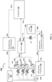
- FIG. 1 exemplarily illustrates a schematic view of a system 100 for detection and correction of reverse flow in an ejector refrigeration circuit according to one or more embodiments of the invention.
- the ejector refrigeration circuit includes a high pressure ejector circuit including, in the direction of flow of a circulating refrigerant, a heat rejecting heat exchanger 105, a plurality of ejectors 101, a receiver 106, and at least one compressor 107.
- the ejector refrigeration circuit also includes a refrigerating evaporator flow path including, in the direction of flow of the circulating refrigerant, a liquid pump 108, at least one refrigeration expansion device 109, and at least one refrigeration evaporator 110.
- the heat rejecting heat exchanger 105 includes an inlet side 105a and an outlet side 105b.
- the heat rejecting heat exchanger 105 may also be interchangeably referred to as a gas cooler unit or a condenser.
- the heat rejecting heat exchanger 105 is configured for transferring heat from the refrigerant to the environment thereby reducing the superheat of the refrigerant.
- the heat rejecting heat exchanger 105 may include one or more fans for blowing air through the heat rejecting heat exchanger 105 to enhance the transfer of heat from the refrigerant to the environment. The type and number of the fans used may be adjusted based on the type of the condenser used, etc.
- the cooled refrigerant leaving the heat rejecting heat exchanger 105 at the outlet side 105b is delivered via a high pressure input line and an optional service valve to a primary high pressure input port 101a of the plurality of ejectors 101.
- the plurality of ejectors 101 is adapted to expand the refrigerant to a reduced medium pressure level.
- Each of the plurality of ejectors 101 includes the primary high pressure input port 101a, a secondary low pressure input port 101b, and an output port 101c.
- the primary high pressure input port 101a is in fluid communication with the outlet side 105b of the heat rejecting heat exchanger 105.
- the expanded refrigerant leaves the ejectors 101 through a respective ejector output port 101c and is delivered to an inlet 106a of the receiver 106.
- the receiver 106 includes a liquid outlet 106b and a gas outlet 106c, and the inlet 106a is in fluid communication with the output port 101c of each of the plurality of ejectors 101.
- the refrigerant is separated by means of gravity into a liquid portion collecting at a bottom part of the receiver 106 and a gas phase portion collecting in an upper part of the receiver 106.
- the gas phase portion of the refrigerant leaves the receiver 106 through the gas outlet 106c provided at the upper part of the receiver 106 and is delivered to the inlet side 107a of the at least one compressor 107 completing the refrigerant cycle of the high pressure ejector circuit.
- the at least one compressor 107 includes the inlet side 107a and an outlet side 107b.
- the inlet side 107a of the at least one compressor 107 is in fluid communication with the gas outlet 106c of the receiver 106 and the outlet side 107b of the at least one compressor 107 is in fluid communication with the inlet side 105a of the heat rejecting heat exchanger 105.
- the liquid pump 108 includes an inlet side 108a and an outlet side 108b.
- the inlet side 108a is in fluid communication with the liquid outlet 106b of the receiver 106.
- the liquid pump 108 may be located below the receiver 106. Arranging the liquid pump 108 below the receiver 106 allows using the forces of gravity for supplying the liquid refrigerant from the receiver 106 to the inlet side 108a of the liquid pump 108.
- the liquid pump 108 also includes a bypass-line including a switchable bypass valve 111 allowing refrigerant to selectively bypass the liquid pump 108 by opening the switchable bypass valve 111.
- separate liquid pumps 108 and (optional) bypass-lines may be provided allowing to adjust the pressure of the liquid refrigerant independently.
- the at least one refrigeration expansion device 109 includes an inlet side 109a and an outlet side 109b.
- the inlet side 109a of the at least one refrigeration expansion device 109 is in fluid communication with the outlet side 108b of the liquid pump 108.
- the at least one refrigeration evaporator 110 includes an inlet side 110a and an outlet side 110b.
- the inlet side 110a is in fluid communication with the outlet side 109b of the at least one refrigeration expansion device 109 and the outlet side 110b is in fluid communication with the secondary low pressure input port 101b of each of the plurality of ejectors 101.
- the system 100 includes the plurality of ejectors 101, a plurality of first sensors 102, at least one second sensor 103, and a controller 104.
- Each of the plurality of ejectors 101 includes the primary high pressure input port 101a, the secondary low pressure input port 101b, and the output port 101c.
- each of the plurality of ejectors 101 are controllable variable ejectors 101 as disclosed in the detailed description of FIG. 2 .
- the "ejector 101" may interchangeably be referred to as the "controllable variable ejector 101".
- the plurality of ejectors 101 may be connected in parallel to each other or in a parallel configuration.
- the plurality of ejectors 101 may have different capacities or may all be of the same capacity. If the plurality of ejectors 101 used are controllable variable ejectors 101, the plurality of ejectors 101 may have opening percentages that are adjustable by actuating a needle 126, shown in FIGS. 2A-2B , of the plurality of ejectors 101 by the controller 104. As used herein, the term "opening percentage" is defined and described in detail in the detailed description of FIGS. 2A-2B . Alternatively, each of the plurality of ejectors 101 used may be controllable variable ejectors 101 with a flow valve 112 upstream of the secondary low pressure input port 101b.
- the controller 104 is adapted to open the flow valve 112 to permit refrigerant flow and adapted to close the flow valve 112 to prevent refrigerant flow. In such an implementation, the controller 104 actuates the flow valve 112 between an ON and OFF position to permit or prevent a refrigerant flow towards the secondary low pressure input port 101b of the respective ejector 101.
- Each of the plurality of first sensors 102 is adapted to measure an ejector suction superheat of a refrigerant at the secondary low pressure input port 101b of a corresponding ejector 101 from the plurality of ejectors 101.
- the at least one second sensor 103 is located along a refrigerating evaporator flow path between at least one refrigerant evaporator 110 and the secondary low pressure input port 101b. As such, the at least one second sensor 103 is adapted to measure a superheat of the refrigerant upstream relative to the secondary low pressure input port 101b.
- the controller 104 communicates with each of the plurality of first sensors 102 and the at least one second sensor 103.
- the term "superheat” refers to the increase of the temperature of a refrigerant vapor in comparison to the boiling point of the refrigerant at a given pressure.
- the boiling point of the refrigerant is different at different pressures.
- the boiling point of the refrigerant also changes.
- the plurality of first sensors 102 measure the ejector suction superheat of the refrigerant at the secondary low pressure input port 101b, this means the plurality of first sensors 102 measures the difference between the temperature of the refrigerant vapor at the secondary low pressure input port 101b and the boiling point of the refrigerant at the current operating pressure of the system 100.
- the at least one second sensor 103 measures the superheat of the refrigerant upstream relative to the secondary low pressure input port 101b, this means the at least one second sensor 103 measures the difference between the temperature of the refrigerant vapor located upstream relative to the secondary low pressure input port 101b and the boiling point of the refrigerant at the current operating pressure of the system 100.
- controller 104" may be configured to control the at least one compressor 107, the liquid pump 108, the flow valves 112, and/or the plurality of ejectors 101 if at least one ejector 101 of the plurality of ejectors 101 are variable, based on one or more parameters, for example, a pressure value, a superheat value measured by the plurality of first sensors 102 and the at least one second sensor 103 for operating the ejector refrigeration circuit as efficiently as possible.
- the controller 104 may refer to a single controller 104 or may be construed to encompass one or a combination of microprocessors, suitable logic, circuits, printed circuit boards (PCB), audio interfaces, visual interfaces, haptic interfaces, or the like.
- the controller 104 may include, but is not limited to, a microcontroller, a Reduced Instruction Set Computing (RISC) processor, an Application-Specific Integrated Circuit (ASIC) processor, a Complex Instruction Set Computing (CISC) processor, a central processing unit (CPU), a graphics processing unit (GPU), a state machine, and/or other processing units or circuits.
- RISC Reduced Instruction Set Computing
- ASIC Application-Specific Integrated Circuit
- CISC Complex Instruction Set Computing
- CPU central processing unit
- GPU graphics processing unit
- state machine and/or other processing units or circuits.
- the controller 104 may also include suitable logic, circuits, interfaces, and/or code that may be configured to execute a set of instructions stored in a memory unit.
- the memory unit may include, but is not limited to, Electrically Erasable Programmable Read-only Memory (EEPROM), Random Access Memory (RAM), Read Only Memory (ROM), Hard Disk Drive (HDD), Flash memory, Solid-State Drive (SSD), and/or CPU cache memory.
- EEPROM Electrically Erasable Programmable Read-only Memory
- RAM Random Access Memory
- ROM Read Only Memory
- HDD Hard Disk Drive
- Flash memory Solid-State Drive
- SSD Solid-State Drive
- the controller 104 may also include a communication unit adapted to communicate with a computing device via a communication network.
- the communication unit may be configured of, for example, a telematic transceiver (DCM), a mayday battery, a GPS, a data communication module ASSY, a telephone microphone ASSY, and a telephone antenna ASSY.
- the communication network may include, but is not limited to, a Wide Area Network (WAN), a cellular network, such as a 3G, 4G, or 5G network, an Internet-based mobile ad hoc networks (IMANET), etc.
- WAN Wide Area Network
- IMANET Internet-based mobile ad hoc networks
- the communication network may also include wired media such as a wired network or direct-wired connection, and wireless media such as acoustic, radio frequency (RF), microwave, infrared (IR) and other wireless media.
- the computing device may be implemented as a portion of a small-form factor portable (or mobile) electronic device such as a cell phone, a personal data assistant (PDA), a personal media player device, a wireless web-watch device, a personal headset device, an application specific device, or a hybrid device that include any of the above functions.
- the controller 104 may receive power from a suitably coupled power source (not shown).
- a battery or a power source may be electrically coupled to supply electrical power to the controller 104.
- the power source may be, for example, a battery, such as a rechargeable battery or a non-rechargeable battery.
- suitable batteries include, for example, a lithium battery (such as a lithium-ion battery), a nickel battery (such as a nickel-cadmium battery), and an alkaline battery.
- the controller 104 is adapted to receive the ejector suction superheats measured by the plurality of first sensors 102 and the refrigerant superheat measured by the at least one second sensor 103. Next, the controller 104 determines whether a superheat difference between each of the ejector suction superheats measured by the plurality of first sensors 102 and the refrigerant superheat measured by the at least one second sensor 103 falls below a threshold superheat difference.
- the threshold superheat difference may be user defined, which means the threshold superheat difference may be set and adjusted or modified based on the performance or capacity of the ejector refrigeration circuit.
- the controller 104 identifies a first ejector 101' from the plurality of ejectors 101 as a reverse flow affected ejector.
- the controller 104 determines a second ejector 101" from the plurality of ejectors 101 by comparing opening percentages of the plurality of ejectors 101 such that the second ejector 101" includes the largest opening percentage. It may be appreciated that the second ejector 101" is determined from the plurality of ejectors 101 excluding the identified first ejector 101'.
- the controller 104 increases the opening percentage of the first ejector 101' and reduces the opening percentage of the second ejector 101" simultaneously to increase a refrigerant flow rate of the first ejector 101'.
- the recovery step is performed by increasing the opening percentage of the first ejector 101' which is the reverse flow affected ejector 101 and simultaneously reducing the opening percentage of the second ejector 101" which has the largest opening percentage.
- the recovery step is performed until the superheat difference between the ejector suction superheats and the refrigerant superheat measured by the at least one second sensor 103 fall within the threshold superheat difference.
- the recovery step ensures a motive flow rate in the inlet 106a of the receiver 106 is kept constant while preventing maintaining the high pressure in the ejector refrigeration circuit.
- the refrigerant superheat measured by the at least one second sensor 103 may be between 8K and 14K in nominal condition that is when the ejector 101 is not under reverse flow.
- the ejector suction superheat of each of the ejectors 101 is a few Kelvin, for example, 1K, 2K, etc., higher than the refrigerant superheat measured by the at least one second sensor 103. Therefore, the threshold superheat difference between the ejector suction superheat and the refrigerant superheat may range between 4-5K.
- the threshold superheat difference falls below 4K and the ejector suction superheat of the reverse flow affected ejector 101 may go down to zero.
- the condition of more than one ejector 101 having a superheat difference below the threshold superheat difference may occur. If the determined superheat difference of more than one ejector 101 from the plurality of ejectors 101 falls below the threshold superheat difference, the controller 104 is adapted to determine a third ejector 101′′′ and the second ejector 101" from more than one ejector 101 by comparing opening percentages of the more than one ejector 101 having the superheat difference below the threshold superheat difference such that the third ejector 101′′′ includes the smallest opening percentage and the second ejector 101" includes the largest opening percentage.
- the controller 104 identifies an ejector (101', 101", or 101′′′) having a negative estimated suction flow (via a mathematical model) as the reverse flow affected ejector. If none of the plurality of ejectors 101 or if more than one ejector, for example, the first ejector 101', the second ejector 101", and the third ejector 101′′′ satisfy the condition of the negative estimated suction flow, the ejector with the smallest opening percentage is selected. For example, if the second ejector 101" has the largest opening percentage and the third ejector 101′′′ has the smallest opening percentage, the controller 104 identifies the third ejector 101′′′ as the reverse flow affected ejector.
- the controller 104 proceeds to identify the third ejector 101′′′ having the smallest opening percentage as the reverse flow affected ejector 101. Finally, the controller 104 performs the recovery step by simultaneously increasing the opening percentage of the third ejector 101′′′ and reducing the opening percentage of the second ejector 101" to increase a refrigerant flow rate of the third ejector 101′′′. The recovery step is performed until the superheat difference between the ejector suction superheats and the refrigerant superheat measured by the at least one second sensor 103 fall within the threshold superheat difference.
- an ejector is identified as the reverse flow affected ejector 101 by the controller 104 if at least one of the following conditions are satisfied in order of priority:
- FIG. 2A exemplarily illustrates a schematic sectional view of the controllable variable ejector 101 as it may be employed in the exemplary embodiment shown in FIG. 1 .
- Each of the plurality of ejectors 101 includes the primary high pressure input port 101a, the secondary low pressure input port 101b, and the output port 101c.
- the ejector 101 is formed by a motive nozzle 113 nested within an outer member 114.
- the primary high pressure input port 101a forms the inlet to the motive nozzle 113.
- the outlet of the outer member 114 provides the output port 101c of the ejector 101.
- a primary refrigerant flow 115 enters the primary high pressure input port 101a and then passes into a convergent section 116 of the motive nozzle 113.
- the primary refrigerant flow 115 then passes through a throat section 117 and a divergent expansion section 118 to an outlet 119 of the motive nozzle 113.
- the motive nozzle 113 accelerates the primary refrigerant flow 115 and decreases the pressure of the primary refrigerant flow 115.
- the secondary low pressure input port 101b forms an inlet of the outer member 114.
- the pressure reduction caused to the primary flow by the motive nozzle 113 draws a secondary flow 120 into the outer member 114.
- the outer member 114 includes a mixer having a convergent section 121 and an elongate throat or mixing section 122.
- the outer member 114 also has a divergent section or diffuser 123 downstream of the elongate throat or mixing section 122.
- the outlet 119 of the motive nozzle 113 is positioned within the convergent section 121.
- the primary refrigerant flow 115 exits the outlet 119, the primary refrigerant flow 115 begins to mix with the secondary flow 120 with further mixing occurring through the elongated throat or mixing section 122 which provides a mixing zone.
- respective primary and secondary flow paths respectively extend from the primary high pressure input port 101a and the secondary low pressure input port 101b to the output port 101c, merging at the exit.
- the primary refrigerant flow 115 may be supercritical upon entering the controllable variable ejector 101 and subcritical upon exiting the motive nozzle 113.
- the secondary flow 120 may be gaseous or a mixture of gas with a smaller amount of liquid upon entering the secondary low pressure input port 101b.
- the resulting combined flow 124 is a liquid/vapor mixture and decelerates and recovers pressure in the diffuser 123 while remaining a mixture.
- the controllability of the controllable variable ejector 101 is provided by a needle valve 125 having a needle 126 and an actuator 127.
- the actuator 127 is adapted to move a tip portion 128 of the needle 126 into and out of the throat section 117 of the motive nozzle 113 to modulate the primary refrigerant flow 115 through the motive nozzle 113 and, in turn, the controllable variable ejector 101 overall.
- each of the plurality of ejectors 101 may have throat sections 117 having different diameters.
- each of the plurality of ejectors 101 may have throat sections 117 having equal diameters.
- the term "opening percentage" refers to the percentage of opening of the throat section 117.
- the opening percentage of the throat section 117 is controlled to range between 0-100 percent, such that the opening percentage of zero percent restricts the primary refrigerant flow 115 completely and the opening percentage of 100 percent allows the primary refrigerant flow 115 completely.
- the actuators 127 may be an electric actuator, for example, a solenoid or the like.
- the controller 104 disclosed in the detailed description of FIG. 1 may be coupled to the actuator 127 and other controllable components of the controllable variable ejector 101 using hardwired or wireless communication paths.
- the controller 104 may store a mathematical model to estimate the suction and motive flow rate.
- the controller 104 may extract signals from sensors such as temperature sensors, pressure sensors, and the like to determine one or more parameters for use in the mathematical model.
- the controller uses a motive Pressure, a motive temperature, a diameter of an Ejector needle opening, a diffuser Pressure, a Suction Pressure, etc., to estimate the suction flow rates and motive flow rates dynamically during operation. This allows the controller 104 to improve the accuracy of reverse flow detection.
- FIG. 2B exemplarily illustrates a schematic sectional view of the controllable ejector 101 under a reverse flow condition.
- the combined flow 124 When affected by the reverse flow condition, the combined flow 124 is reversed and moves from the output port 101c to the secondary low pressure input port 101b.
- the combined flow 124 mixes with the primary refrigerant flow 115 and combines with the secondary flow 120 to exit through the secondary low pressure input port 101b.
- FIG. 3 exemplarily illustrates a flowchart indicating a method 300 for detection and correction of reverse flow in the ejector refrigeration circuit. While the steps of FIG. 3 are shown and described in a particular sequence, the steps may occur in variations to the sequence in accordance with various embodiments of the invention. Further, the details related to various steps of FIG. 3 , which are already covered in the description related to FIGS. 1-3 are not discussed again in detail here for the sake of brevity.
- the method 300 for detection and correction of reverse flow in an ejector refrigeration circuit is disclosed.
- each of the plurality of first sensors 102 measures the ejector suction superheat of the refrigerant at the secondary low pressure input port 101b of the corresponding ejector 101 from the plurality of ejectors 101.
- Each of the plurality of ejectors 101 includes the primary high pressure input port 101a, the secondary low pressure input port 101b, and the output port 101c as exemplarily illustrated in FIG. 2 .
- the at least one second sensor 103 measures the superheat of the refrigerant upstream relative to the secondary low pressure input port 101b.
- the at least one second sensor 103 is located along a refrigerating evaporator flow path between the at least one refrigerant evaporator 110 and the secondary low pressure input port 101b.
- the controller 104 receives the ejector suction superheats measured by the plurality of first sensors 102 and the refrigerant superheat measured by the at least one second sensor 103.
- the controller 104 determines whether a superheat difference between each of the ejector suction superheats measured by the plurality of first sensors 102 and the refrigerant superheat measured by the at least one second sensor 103 falls below a threshold superheat difference.
- the controller 104 identifies a first ejector 101' from the plurality of ejectors 101 as a reverse flow affected ejector based on the determined superheat difference of the first ejector 101'.
- the condition of more than one ejector 101 having the superheat difference below the threshold superheat difference may occur. If the determined superheat difference of more than one ejector 101 from the plurality of ejectors 101 falls below the threshold superheat difference, the controller 104 is adapted to determine a third ejector 101′′′ and the second ejector 101" from more than one ejector 101 by comparing opening percentages of the more than one ejector 101 having the superheat difference below the threshold superheat difference such that the third ejector 101′′′ includes the smallest opening percentage and the second ejector 101" includes the largest opening percentage.
- the controller 104 identifies the third ejector 101′′′ as the reverse flow affected ejector 101 from the more than one ejectors 101 having the superheat difference below the threshold superheat difference. It may be appreciated that the criteria for identifying the reverse flow affected ejector 101 is the smallest opening percentage. As such, the ejector 101 from among the more than one ejector 101 having the smallest opening percentage is identified as the reverse flow affected ejector 101.
- the controller 104 performs the recovery step by simultaneously increasing the opening percentage of the third ejector 101′′′ and reducing the opening percentage of the second ejector 101" to increase the refrigerant flow rate of the third ejector 101′′′.
- the recovery step is performed until the superheat difference between the ejector suction superheats and the refrigerant superheat measured by the at least one second sensor 103 fall within the threshold superheat difference.
- the controller 104 determines a second ejector 101" from the plurality of ejectors 101 by comparing opening percentages of the plurality of ejectors 101, such that the second ejector 101" includes the largest opening percentage.
- the controller increases the opening percentage of the first ejector 101' and reduces the opening percentage of the second ejector 101" to increase a refrigerant flow rate of the first ejector 101'.
- Existing ejector control systems preset the ejectors 101 that can be used simultaneously. These preset opening configurations, for example, increasing the opening percentage of the first ejector 101' followed by reducing the opening percentage of the second ejector 101" and so on may be safe with regards to the reverse flow. However, by limiting the opening percentages to preset sequences, the ejector refrigeration circuit is prevented from reaching optimal performance.
- the dynamic detection of the reverse flow affected ejector 101 based on the determined superheat difference falling below the threshold superheat difference allows the controller 104 to proactively perform the recovery step. This feature helps optimize the overall efficiency of the ejector refrigeration circuit.
Landscapes
- Engineering & Computer Science (AREA)
- Physics & Mathematics (AREA)
- Mechanical Engineering (AREA)
- General Engineering & Computer Science (AREA)
- Fluid Mechanics (AREA)
- Thermal Sciences (AREA)
- Jet Pumps And Other Pumps (AREA)
- Compression-Type Refrigeration Machines With Reversible Cycles (AREA)
Abstract
A system (100) for detection and correction of reverse flow in an ejector refrigeration circuit, includes ejectors (101), first sensors (102) for measuring an ejector suction superheat of a refrigerant at a secondary low pressure input port (101b) of each of the ejectors (101), and a second sensor (103) for measuring a superheat of the refrigerant upstream relative to the secondary low pressure input port (101b). A controller (104) receives the ejector suction superheats and the refrigerant superheat and determines whether a superheat difference between each of the ejector suction superheats and the refrigerant superheat falls below a threshold superheat difference. The controller (104) identifies a first ejector (101') as a reverse flow affected ejector based on the determined superheat difference. The controller (104) compares opening percentages of the ejectors to determine a second ejector (101") having the largest opening percentage and controls the first ejector (101') and the second ejector (101") to increase a refrigerant flow rate of the first ejector (101').
Description
- This application claims the benefit of
U.S. Provisional Patent Application No. 63/511,308 filed on June 30, 2023 - The invention generally relates to ejector refrigeration circuits. More particularly, the invention relates to a system for detection and correction of reverse flow in an ejector refrigeration circuit.
- Ejectors are sometimes used to improve overall efficiency of commercial refrigeration systems. The ejectors improve efficiency in the refrigeration system by utilizing a high pressure to help compress a low pressure gas, instead of relying solely on a compressor.
- Typically, the ejectors may be located between an outlet of a condenser and an inlet of a receiver tank. The ejectors include a primary high pressure inlet, a secondary low pressure inlet, and an outlet. When an ejector is used as part of the refrigeration system, the cooled refrigerant from the heat exchanger enters each of the ejectors at the high pressure inlet and is expanded to a lower pressure at the outlet of each of the ejectors. At the outlet of the ejectors, the refrigerant flow will typically be both liquid and gaseous phase. The gaseous phase will be fed back to a compressor, while the liquid phase is fed through another expansion valve and then the evaporator. The fluid that leaves the evaporator then flows to the low pressure inlet of the ejector. The inclusion of the ejectors reduces a load on the compressor as the compressor can operate at a lower pressure difference and use less energy since the ejectors have partially compressed the refrigerant vapors to the intermediate pressure level.
- However, when the ejectors are operated, if the high pressure fluid and the outlet fluid flow back to the secondary low pressure inlet, a large loss of compressor efficiency will result. Therefore, a reverse flow detection system that helps to detect a backflow or reverse flow of the refrigerant within the ejectors, is therefore desirable.
- This summary is provided to introduce a selection of concepts in a simplified format that are further described in the detailed description. This summary is not intended to identify key or essential inventive concepts of the invention, nor is it intended for determining the scope of the invention as set out in the appended claims.
- According to a first aspect of the invention there is provided a system for detection and correction of reverse flow in an ejector refrigeration circuit. The system includes a plurality of ejectors, a plurality of first sensors, at least one second sensor, and a controller. Each of the plurality of ejectors include a primary high pressure input port, a secondary low pressure input port, and an output port. Each of the plurality of first sensors is adapted to measure an ejector suction superheat of a refrigerant at the secondary low pressure input port of a corresponding ejector from the plurality of ejectors. The at least one second sensor is located along a refrigerating evaporator flow path between at least one refrigerant evaporator and the secondary low pressure input port. The at least one second sensor is adapted to measure a superheat of the refrigerant upstream relative to the secondary low pressure input port. The controller is adapted to receive the ejector suction superheats measured by the plurality of first sensors and the refrigerant superheat measured by the at least one second sensor. The controller determines whether a superheat difference between each of the ejector suction superheats and the refrigerant superheat falls below a threshold superheat difference. The controller then identifies a first ejector from the plurality of ejectors as a reverse flow affected ejector based on the determined superheat difference.
Next, the controller determines a second ejector from the plurality of ejectors by comparing opening percentages of the plurality of ejectors, such that the second ejector includes the largest opening percentage. The controller increases the opening percentage of the first ejector and reduces the opening percentage of the second ejector to increase a refrigerant flow rate of the first ejector. - Optionally, identifying the reverse flow affected ejector includes, in an order of priority, at least one of:
- a) the controller identifying the first ejector from the plurality of ejectors as the reverse flow affected ejector if the determined superheat difference of only the first ejector falls below the threshold superheat difference;
- b) the controller identifying an ejector that has a negative estimated suction flow from the plurality of ejectors as the reverse flow affected ejector if the determined superheat difference of more than one ejector from the plurality of ejectors falls below the threshold superheat difference;
- c) the controller identifying a third ejector having the smallest opening percentage as the reverse flow affected ejector if the estimated suction flow of none or more than one ejector from the plurality of ejectors falls below zero.
- Optionally, if the determined superheat difference of more than one ejector from the plurality of ejectors falls below the threshold superheat difference, the controller is adapted to determine a third ejector and the second ejector from more than one ejector by comparing the opening percentages of more than one ejector having the superheat difference below the threshold superheat difference, such that the third ejector includes the smallest opening percentage and the second ejector includes the largest opening percentage. The controller identifies the third ejector having the smallest opening percentage from more than one ejector as a reverse flow affected ejector. Finally, the controller increases the opening percentage of the third ejector and reduces the opening percentage of the second ejector to increase a refrigerant flow rate of the third ejector.
- Optionally, each of the plurality of ejectors are controllable variable ejectors connected in a parallel configuration.
- Optionally, the plurality of ejectors have different capacities.
- Optionally, wherein the plurality of ejectors have throat sections of different diameters.
- Optionally, each of the plurality of ejectors are controllable variable ejectors with a flow valve upstream of the secondary low pressure input port.
- Optionally, the controller is adapted to open the flow valve to permit refrigerant flow and adapted to close the flow valve to prevent refrigerant flow.
- Optionally, the ejector refrigeration circuit includes a high pressure ejector circuit and a refrigerating evaporator flow path. The high pressure ejector circuit includes, in a direction of flow of a circulating refrigerant, a heat rejecting heat exchanger, the plurality of ejectors, a receiver, and at least one compressor. The refrigerating evaporator flow path includes, in the direction of flow of the circulating refrigerant, a liquid pump, at least one refrigeration expansion device, and at least one refrigerant evaporator. The heat rejecting heat exchanger includes an inlet side and an outlet side. Each of the plurality of ejectors include the primary high pressure input port, the secondary low pressure input port, and the output port, such that the primary high pressure input port is in fluid communication with the outlet side of the heat rejecting heat exchanger. The receiver includes an inlet, a liquid outlet, and a gas outlet, such that the inlet is in fluid communication with the output port of each of the plurality of ejectors. The at least one compressor includes an inlet side and an outlet side. The inlet side of the at least one compressor is in fluid communication with the gas outlet of the receiver and the outlet side of the at least one compressor is in fluid communication with the inlet side of the heat rejecting heat exchanger. The liquid pump includes an inlet side and an outlet side, such that the inlet side is in fluid communication with the liquid outlet of the receiver. The at least one refrigeration expansion device includes an inlet side and an outlet side, such that the inlet side of the at least one refrigeration expansion device is in fluid communication with the outlet side of the liquid pump. The at least one refrigeration evaporator includes an inlet side and an outlet side, such that the inlet side is in fluid communication with the outlet side of the at least one refrigeration expansion device and the outlet side is in fluid communication with the secondary low pressure input port of each of the plurality of ejectors.
- Optionally, the liquid pump includes a bypass-line having a switchable bypass valve for allowing refrigerant to selectively bypass the liquid pump by opening the switchable bypass valve.
- According to a second aspect of the invention there is provided a method for detection and correction of reverse flow in an ejector refrigeration circuit. The method includes measuring, via each of a plurality of first sensors, an ejector suction superheat of a refrigerant at a secondary low pressure input port of a corresponding ejector from a plurality of ejectors. Next, at least one second sensor measures a superheat of the refrigerant upstream relative to the secondary low pressure input port. A controller receives the measured ejector suction superheats and the refrigerant superheat. The controller determines whether a superheat difference between each of the ejector suction superheats measured by the plurality of first sensors and the refrigerant superheat measured by the at least one second sensor falls below a threshold superheat difference. The controller identifies a first ejector from the plurality of ejectors as a reverse flow affected ejector based on the determined superheat difference of the first ejector. The controller determines a second ejector from the plurality of ejectors by comparing opening percentages of the plurality of ejectors, such that the second ejector has the largest opening percentage. Finally, the controller increases the opening percentage of the first ejector and reduces the opening percentage of the second ejector to increase a refrigerant flow rate of the first ejector.
- Optionally, the at least one second sensor is located along a refrigerating evaporator flow path between at least one refrigerant evaporator and the secondary low pressure input port.
- Optionally, each of the plurality of ejectors include a primary high pressure input port, the secondary low pressure input port, and an output port.
- Optionally, identifying the reverse flow affected ejector includes, in an order of priority, at least one of:
- a) the controller identifying the first ejector from the plurality of ejectors as the reverse flow affected ejector if the determined superheat difference of only the first ejector falls below the threshold superheat difference;
- b) the controller identifying an ejector that has a negative estimated suction flow from the plurality of ejectors as the reverse flow affected ejector if the determined superheat difference of more than one ejector from the plurality of ejectors falls below the threshold superheat difference;
- c) the controller identifying a third ejector having the smallest opening percentage as the reverse flow affected ejector if the estimated suction flow of none or more than one ejector from the plurality of ejectors falls below zero.
- Optionally, if the determined superheat difference of more than one ejector from the plurality of ejectors falls below the threshold superheat difference, the controller is adapted to determine a third ejector and the second ejector from more than one ejector by comparing opening percentages of more than one ejector having the superheat difference below the threshold superheat difference, such that the third ejector has the smallest opening percentage and the second ejector has the largest opening percentage. The controller identifies the third ejector having the smallest opening percentage from more than one ejector as a reverse flow affected ejector. The controller increases the opening percentage of the third ejector and reduces the opening percentage of the second ejector to increase a refrigerant flow rate of the third ejector.
- Optionally, each of the plurality of ejectors are controllable variable ejectors connected in a parallel configuration.
- Optionally, the plurality of ejectors have different capacities.
- Optionally, the plurality of ejectors have throat sections of different diameters.
- Optionally, each of the plurality of ejectors are controllable variable ejectors with a flow valve upstream of the secondary low pressure input port.
- Optionally, the controller is adapted to open the flow valve to permit refrigerant flow and adapted to close the flow valve to prevent refrigerant flow.
- Optionally, the ejector refrigeration circuit includes a high pressure ejector circuit and a refrigerating evaporator flow path. The high pressure ejection circuit includes, in a direction of flow of a circulating refrigerant, a heat rejecting heat exchanger, the plurality of ejectors, a receiver, and at least one compressor. The heat rejecting heat exchanger includes an inlet side and an outlet side. Each of the plurality of ejectors include the primary high pressure input port, the secondary low pressure input port, and the output port, such that the primary high pressure input port is in fluid communication with the outlet side of the heat rejecting heat exchanger. The receiver includes an inlet, a liquid outlet, and a gas outlet, such that the inlet is in fluid communication with the output port of each of the plurality of ejectors. The at least one compressor includes an inlet side and an outlet side, such that the inlet side of the at least one compressor is in fluid communication with the gas outlet of the receiver and the outlet side of the at least one compressor is in fluid communication with the inlet side of the heat rejecting heat exchanger. The refrigerating evaporator flow path includes, in the direction of flow of the circulating refrigerant, a liquid pump, at least one refrigeration expansion device, and at least one refrigerant evaporator. The liquid pump includes an inlet side and an outlet side, such that the inlet side is in fluid communication with the liquid outlet of the receiver. The at least one refrigeration expansion device includes an inlet side and an outlet side, such that the inlet side of the at least one refrigeration expansion device is in fluid communication with the outlet side of the liquid pump. The at least one refrigeration evaporator includes an inlet side and an outlet side, such that the inlet side is in fluid communication with the outlet side of the at least one refrigeration expansion device and the outlet side is in fluid communication with the secondary low pressure input port of each of the plurality of ejectors.
- Optionally, the liquid pump includes a bypass-line having a switchable bypass valve allowing refrigerant to selectively bypass the liquid pump by opening the switchable bypass valve.
- To further clarify the advantages and features of the methods, systems, and apparatuses, a more particular description of the methods, systems, and apparatuses will be rendered by reference to specific embodiments thereof, which are illustrated in the appended drawings. It is appreciated that these drawings depict only typical embodiments of the invention and are therefore not to be considered limiting of its scope. The invention will be described and explained by way of example only with additional specificity and detail with reference to the accompanying drawings.
- These and other features and advantages of embodiments of the invention will become better understood when the following detailed description is read with reference to the accompanying drawings in which like characters represent like parts throughout the drawings, wherein:
-
FIG. 1 shows a schematic view of a system for detection and correction of reverse flow in an ejector refrigeration circuit; -
FIG. 2A shows a schematic sectional view of a controllable ejector as it may be employed in the system ofFIG. 1 ; -
FIG. 2B shows a schematic sectional view of the controllable ejector ofFig. 2A under a reverse flow condition; and -
FIG. 3 shows a flowchart indicating a method for detection and correction of reverse flow in the ejector refrigeration circuit. - Further, skilled artisans will appreciate that elements in the drawings are illustrated for simplicity and may not have necessarily been drawn to scale. For example, the flow charts illustrate the method in terms of the most prominent steps involved to help to improve understanding of features of embodiments of the invention. Furthermore, in terms of the construction of the device, one or more components of the device may have been represented in the drawings by conventional symbols, and the drawings may show only those specific details that are pertinent to understanding the embodiments of the invention so as not to obscure the drawings with details that will be readily apparent to those of ordinary skill in the art having the benefit of the description herein.
- For the purpose of promoting an understanding of the principles of the invention, reference will now be made to the various embodiments and specific language will be used to describe the same. It will nevertheless be understood that no limitation of the scope of the invention, as set out in the appended claims, is thereby intended, such alterations and further modifications in the illustrated system, and such further applications of the principles of the invention as illustrated therein being contemplated as would normally occur to one skilled in the art to which the invention relates.
- It will be understood by those skilled in the art that the foregoing general description and the following detailed description are explanatory of the invention and are not intended to be restrictive thereof.
- Appearances of the phrase "in an embodiment", "in another embodiment", "some embodiments", "one or more embodiments" and similar language throughout this specification may, but do not necessarily, all refer to the same embodiment.
- The terms "comprises", "comprising", or any other variations thereof, are intended to cover a non-exclusive inclusion, such that a process or method that comprises a list of steps does not include only those steps but may include other steps not expressly listed or inherent to such process or method. Similarly, one or more devices or sub-systems or elements or structures or components proceeded by "comprises... a" does not, without more constraints, preclude the existence of other devices or other sub-systems or other elements or other structures or other components or additional devices or additional sub-systems or additional elements or additional structures or additional components.
- Embodiments of the invention will be described below in detail with reference to the accompanying drawings.
-
FIG. 1 exemplarily illustrates a schematic view of asystem 100 for detection and correction of reverse flow in an ejector refrigeration circuit according to one or more embodiments of the invention. - In an exemplary embodiment of the invention, the ejector refrigeration circuit includes a high pressure ejector circuit including, in the direction of flow of a circulating refrigerant, a heat rejecting
heat exchanger 105, a plurality ofejectors 101, areceiver 106, and at least onecompressor 107. The ejector refrigeration circuit also includes a refrigerating evaporator flow path including, in the direction of flow of the circulating refrigerant, aliquid pump 108, at least onerefrigeration expansion device 109, and at least onerefrigeration evaporator 110. - The heat rejecting
heat exchanger 105 includes aninlet side 105a and anoutlet side 105b. The heat rejectingheat exchanger 105 may also be interchangeably referred to as a gas cooler unit or a condenser. The heat rejectingheat exchanger 105 is configured for transferring heat from the refrigerant to the environment thereby reducing the superheat of the refrigerant. In an embodiment, the heat rejectingheat exchanger 105 may include one or more fans for blowing air through the heat rejectingheat exchanger 105 to enhance the transfer of heat from the refrigerant to the environment. The type and number of the fans used may be adjusted based on the type of the condenser used, etc. The cooled refrigerant leaving the heat rejectingheat exchanger 105 at theoutlet side 105b is delivered via a high pressure input line and an optional service valve to a primary highpressure input port 101a of the plurality ofejectors 101. - The plurality of
ejectors 101 is adapted to expand the refrigerant to a reduced medium pressure level. Each of the plurality ofejectors 101 includes the primary highpressure input port 101a, a secondary lowpressure input port 101b, and anoutput port 101c. The primary highpressure input port 101a is in fluid communication with theoutlet side 105b of the heat rejectingheat exchanger 105. The expanded refrigerant leaves theejectors 101 through a respectiveejector output port 101c and is delivered to aninlet 106a of thereceiver 106. Moreover, thereceiver 106 includes aliquid outlet 106b and agas outlet 106c, and theinlet 106a is in fluid communication with theoutput port 101c of each of the plurality ofejectors 101. Within thereceiver 106, the refrigerant is separated by means of gravity into a liquid portion collecting at a bottom part of thereceiver 106 and a gas phase portion collecting in an upper part of thereceiver 106. The gas phase portion of the refrigerant leaves thereceiver 106 through thegas outlet 106c provided at the upper part of thereceiver 106 and is delivered to theinlet side 107a of the at least onecompressor 107 completing the refrigerant cycle of the high pressure ejector circuit. - The at least one
compressor 107 includes theinlet side 107a and anoutlet side 107b. Theinlet side 107a of the at least onecompressor 107 is in fluid communication with thegas outlet 106c of thereceiver 106 and theoutlet side 107b of the at least onecompressor 107 is in fluid communication with theinlet side 105a of the heat rejectingheat exchanger 105. - The
liquid pump 108 includes aninlet side 108a and anoutlet side 108b. Theinlet side 108a is in fluid communication with theliquid outlet 106b of thereceiver 106. In an embodiment, theliquid pump 108 may be located below thereceiver 106. Arranging theliquid pump 108 below thereceiver 106 allows using the forces of gravity for supplying the liquid refrigerant from thereceiver 106 to theinlet side 108a of theliquid pump 108. Theliquid pump 108 also includes a bypass-line including aswitchable bypass valve 111 allowing refrigerant to selectively bypass theliquid pump 108 by opening theswitchable bypass valve 111. In an embodiment, separate liquid pumps 108 and (optional) bypass-lines may be provided allowing to adjust the pressure of the liquid refrigerant independently. - The at least one
refrigeration expansion device 109 includes aninlet side 109a and anoutlet side 109b. Theinlet side 109a of the at least onerefrigeration expansion device 109 is in fluid communication with theoutlet side 108b of theliquid pump 108. The at least onerefrigeration evaporator 110 includes aninlet side 110a and anoutlet side 110b. Theinlet side 110a is in fluid communication with theoutlet side 109b of the at least onerefrigeration expansion device 109 and theoutlet side 110b is in fluid communication with the secondary lowpressure input port 101b of each of the plurality ofejectors 101. - The
system 100 includes the plurality ofejectors 101, a plurality offirst sensors 102, at least onesecond sensor 103, and acontroller 104. Each of the plurality ofejectors 101 includes the primary highpressure input port 101a, the secondary lowpressure input port 101b, and theoutput port 101c. In an embodiment, each of the plurality ofejectors 101 are controllablevariable ejectors 101 as disclosed in the detailed description ofFIG. 2 . Hereinafter, the "ejector 101" may interchangeably be referred to as the "controllablevariable ejector 101". Moreover, the plurality ofejectors 101 may be connected in parallel to each other or in a parallel configuration. The plurality ofejectors 101 may have different capacities or may all be of the same capacity. If the plurality ofejectors 101 used are controllablevariable ejectors 101, the plurality ofejectors 101 may have opening percentages that are adjustable by actuating aneedle 126, shown inFIGS. 2A-2B , of the plurality ofejectors 101 by thecontroller 104. As used herein, the term "opening percentage" is defined and described in detail in the detailed description ofFIGS. 2A-2B . Alternatively, each of the plurality ofejectors 101 used may be controllablevariable ejectors 101 with aflow valve 112 upstream of the secondary lowpressure input port 101b. In an embodiment, thecontroller 104 is adapted to open theflow valve 112 to permit refrigerant flow and adapted to close theflow valve 112 to prevent refrigerant flow. In such an implementation, thecontroller 104 actuates theflow valve 112 between an ON and OFF position to permit or prevent a refrigerant flow towards the secondary lowpressure input port 101b of therespective ejector 101. - Each of the plurality of
first sensors 102 is adapted to measure an ejector suction superheat of a refrigerant at the secondary lowpressure input port 101b of acorresponding ejector 101 from the plurality ofejectors 101. The at least onesecond sensor 103 is located along a refrigerating evaporator flow path between at least onerefrigerant evaporator 110 and the secondary lowpressure input port 101b. As such, the at least onesecond sensor 103 is adapted to measure a superheat of the refrigerant upstream relative to the secondary lowpressure input port 101b. Thecontroller 104 communicates with each of the plurality offirst sensors 102 and the at least onesecond sensor 103. - As used herein, the term "superheat" refers to the increase of the temperature of a refrigerant vapor in comparison to the boiling point of the refrigerant at a given pressure. The boiling point of the refrigerant is different at different pressures. As the operating pressure of the
system 100 changes, the boiling point of the refrigerant also changes. When the plurality offirst sensors 102 measure the ejector suction superheat of the refrigerant at the secondary lowpressure input port 101b, this means the plurality offirst sensors 102 measures the difference between the temperature of the refrigerant vapor at the secondary lowpressure input port 101b and the boiling point of the refrigerant at the current operating pressure of thesystem 100. Similarly, when the at least onesecond sensor 103 measures the superheat of the refrigerant upstream relative to the secondary lowpressure input port 101b, this means the at least onesecond sensor 103 measures the difference between the temperature of the refrigerant vapor located upstream relative to the secondary lowpressure input port 101b and the boiling point of the refrigerant at the current operating pressure of thesystem 100. - As used herein, the "
controller 104" may be configured to control the at least onecompressor 107, theliquid pump 108, theflow valves 112, and/or the plurality ofejectors 101 if at least oneejector 101 of the plurality ofejectors 101 are variable, based on one or more parameters, for example, a pressure value, a superheat value measured by the plurality offirst sensors 102 and the at least onesecond sensor 103 for operating the ejector refrigeration circuit as efficiently as possible. In an embodiment, thecontroller 104 may refer to asingle controller 104 or may be construed to encompass one or a combination of microprocessors, suitable logic, circuits, printed circuit boards (PCB), audio interfaces, visual interfaces, haptic interfaces, or the like. Thecontroller 104 may include, but is not limited to, a microcontroller, a Reduced Instruction Set Computing (RISC) processor, an Application-Specific Integrated Circuit (ASIC) processor, a Complex Instruction Set Computing (CISC) processor, a central processing unit (CPU), a graphics processing unit (GPU), a state machine, and/or other processing units or circuits. - The
controller 104 may also include suitable logic, circuits, interfaces, and/or code that may be configured to execute a set of instructions stored in a memory unit. In an exemplary implementation of the memory unit according to embodiments of the invention, the memory unit may include, but is not limited to, Electrically Erasable Programmable Read-only Memory (EEPROM), Random Access Memory (RAM), Read Only Memory (ROM), Hard Disk Drive (HDD), Flash memory, Solid-State Drive (SSD), and/or CPU cache memory. - The
controller 104 may also include a communication unit adapted to communicate with a computing device via a communication network. The communication unit may be configured of, for example, a telematic transceiver (DCM), a mayday battery, a GPS, a data communication module ASSY, a telephone microphone ASSY, and a telephone antenna ASSY. The communication network may include, but is not limited to, a Wide Area Network (WAN), a cellular network, such as a 3G, 4G, or 5G network, an Internet-based mobile ad hoc networks (IMANET), etc. The communication network may also include wired media such as a wired network or direct-wired connection, and wireless media such as acoustic, radio frequency (RF), microwave, infrared (IR) and other wireless media. In an embodiment, the computing device may be implemented as a portion of a small-form factor portable (or mobile) electronic device such as a cell phone, a personal data assistant (PDA), a personal media player device, a wireless web-watch device, a personal headset device, an application specific device, or a hybrid device that include any of the above functions. - In an exemplary embodiment, the
controller 104 may receive power from a suitably coupled power source (not shown). For example, a battery or a power source may be electrically coupled to supply electrical power to thecontroller 104. In an embodiment, the power source may be, for example, a battery, such as a rechargeable battery or a non-rechargeable battery. Examples of suitable batteries include, for example, a lithium battery (such as a lithium-ion battery), a nickel battery (such as a nickel-cadmium battery), and an alkaline battery. - The
controller 104 is adapted to receive the ejector suction superheats measured by the plurality offirst sensors 102 and the refrigerant superheat measured by the at least onesecond sensor 103. Next, thecontroller 104 determines whether a superheat difference between each of the ejector suction superheats measured by the plurality offirst sensors 102 and the refrigerant superheat measured by the at least onesecond sensor 103 falls below a threshold superheat difference. In an embodiment, the threshold superheat difference may be user defined, which means the threshold superheat difference may be set and adjusted or modified based on the performance or capacity of the ejector refrigeration circuit. - If the determined superheat difference of the first ejector 101' falls below the threshold superheat difference, the
controller 104 identifies a first ejector 101' from the plurality ofejectors 101 as a reverse flow affected ejector. Next, thecontroller 104 determines asecond ejector 101" from the plurality ofejectors 101 by comparing opening percentages of the plurality ofejectors 101 such that thesecond ejector 101" includes the largest opening percentage. It may be appreciated that thesecond ejector 101" is determined from the plurality ofejectors 101 excluding the identified first ejector 101'. Finally, thecontroller 104 increases the opening percentage of the first ejector 101' and reduces the opening percentage of thesecond ejector 101" simultaneously to increase a refrigerant flow rate of the first ejector 101'. The recovery step is performed by increasing the opening percentage of the first ejector 101' which is the reverse flow affectedejector 101 and simultaneously reducing the opening percentage of thesecond ejector 101" which has the largest opening percentage. The recovery step is performed until the superheat difference between the ejector suction superheats and the refrigerant superheat measured by the at least onesecond sensor 103 fall within the threshold superheat difference. The recovery step ensures a motive flow rate in theinlet 106a of thereceiver 106 is kept constant while preventing maintaining the high pressure in the ejector refrigeration circuit. - The refrigerant superheat measured by the at least one
second sensor 103 may be between 8K and 14K in nominal condition that is when theejector 101 is not under reverse flow. As such, in the nominal condition shown inFIG. 2A , the ejector suction superheat of each of theejectors 101 is a few Kelvin, for example, 1K, 2K, etc., higher than the refrigerant superheat measured by the at least onesecond sensor 103. Therefore, the threshold superheat difference between the ejector suction superheat and the refrigerant superheat may range between 4-5K. Alternatively, when the reverse flow occurs as shown inFIG. 2B , the threshold superheat difference falls below 4K and the ejector suction superheat of the reverse flow affectedejector 101 may go down to zero. - Alternatively, the condition of more than one
ejector 101 having a superheat difference below the threshold superheat difference may occur. If the determined superheat difference of more than oneejector 101 from the plurality ofejectors 101 falls below the threshold superheat difference, thecontroller 104 is adapted to determine athird ejector 101‴ and thesecond ejector 101" from more than oneejector 101 by comparing opening percentages of the more than oneejector 101 having the superheat difference below the threshold superheat difference such that thethird ejector 101‴ includes the smallest opening percentage and thesecond ejector 101" includes the largest opening percentage. - Referring to
Figure 1 , if the determined superheat difference of the first ejector 101', thesecond ejector 101" and thethird ejector 101‴ fall below the threshold superheat difference, thecontroller 104 identifies an ejector (101', 101", or 101‴) having a negative estimated suction flow (via a mathematical model) as the reverse flow affected ejector. If none of the plurality ofejectors 101 or if more than one ejector, for example, the first ejector 101', thesecond ejector 101", and thethird ejector 101‴ satisfy the condition of the negative estimated suction flow, the ejector with the smallest opening percentage is selected. For example, if thesecond ejector 101" has the largest opening percentage and thethird ejector 101‴ has the smallest opening percentage, thecontroller 104 identifies thethird ejector 101‴ as the reverse flow affected ejector. - From more than one
ejector 101, thecontroller 104 proceeds to identify thethird ejector 101‴ having the smallest opening percentage as the reverse flow affectedejector 101. Finally, thecontroller 104 performs the recovery step by simultaneously increasing the opening percentage of thethird ejector 101‴ and reducing the opening percentage of thesecond ejector 101" to increase a refrigerant flow rate of thethird ejector 101‴. The recovery step is performed until the superheat difference between the ejector suction superheats and the refrigerant superheat measured by the at least onesecond sensor 103 fall within the threshold superheat difference. - In conclusion, an ejector is identified as the reverse flow affected
ejector 101 by thecontroller 104 if at least one of the following conditions are satisfied in order of priority: - 1) If the determined superheat difference of only one ejector, for example, the first ejector 101' falls below the threshold superheat difference, the
controller 104 identifies the first ejector 101' from the plurality ofejectors 101 as the reverse flow affected ejector. The threshold superheat difference between the ejector suction superheat and the refrigerant superheat may range between 4-5K. Alternatively, when the reverse flow occurs as shown inFIG. 2B , the threshold superheat difference falls below 4K and the ejector suction superheat of the reverse flow affectedejector 101 may go down to zero. - 2) If more than one
ejector 101 from the plurality ofejectors 101 meets the above condition, the ejector that has a negative estimated (via mathematical model) suction flow is identified as the reverse flow affectedejector 101. - 3) If none or more than one
ejector 101 meet the previous condition, theejector 101, for example, thethird ejector 101‴ with the smallest opening percentage is identified as the reverse flow affected ejector. This means, if the estimated suction flow of none or more than one ejector from the plurality of ejectors falls below zero, thethird ejector 101‴ with the smallest opening percentage is identified as the reverse flow affected ejector. Only one ejector can be identified as in reverse flow condition. Finally, thecontroller 104 performs the recovery step by simultaneously increasing the opening percentage of thethird ejector 101‴ and reducing the opening percentage of thesecond ejector 101" to increase the refrigerant flow rate of thethird ejector 101‴. The recovery step is performed until the superheat difference between the ejector suction superheats and the refrigerant superheat measured by the at least onesecond sensor 103 fall within the threshold superheat difference. By following this procedure an almost constant motive flow and high pressure is maintained. This minimizes the impact on the high pressure control loop. -
FIG. 2A exemplarily illustrates a schematic sectional view of the controllablevariable ejector 101 as it may be employed in the exemplary embodiment shown inFIG. 1 . Each of the plurality ofejectors 101 includes the primary highpressure input port 101a, the secondary lowpressure input port 101b, and theoutput port 101c. Theejector 101 is formed by amotive nozzle 113 nested within anouter member 114. The primary highpressure input port 101a forms the inlet to themotive nozzle 113. The outlet of theouter member 114 provides theoutput port 101c of theejector 101. Aprimary refrigerant flow 115 enters the primary highpressure input port 101a and then passes into aconvergent section 116 of themotive nozzle 113. Theprimary refrigerant flow 115 then passes through athroat section 117 and adivergent expansion section 118 to anoutlet 119 of themotive nozzle 113. Themotive nozzle 113 accelerates theprimary refrigerant flow 115 and decreases the pressure of theprimary refrigerant flow 115. The secondary lowpressure input port 101b forms an inlet of theouter member 114. The pressure reduction caused to the primary flow by themotive nozzle 113 draws asecondary flow 120 into theouter member 114. Theouter member 114 includes a mixer having aconvergent section 121 and an elongate throat or mixingsection 122. Theouter member 114 also has a divergent section ordiffuser 123 downstream of the elongate throat or mixingsection 122. Theoutlet 119 of themotive nozzle 113 is positioned within theconvergent section 121. As theprimary refrigerant flow 115 exits theoutlet 119, theprimary refrigerant flow 115 begins to mix with thesecondary flow 120 with further mixing occurring through the elongated throat or mixingsection 122 which provides a mixing zone. Thus, respective primary and secondary flow paths respectively extend from the primary highpressure input port 101a and the secondary lowpressure input port 101b to theoutput port 101c, merging at the exit. - In operation, the
primary refrigerant flow 115 may be supercritical upon entering the controllablevariable ejector 101 and subcritical upon exiting themotive nozzle 113. Thesecondary flow 120 may be gaseous or a mixture of gas with a smaller amount of liquid upon entering the secondary lowpressure input port 101b. The resulting combinedflow 124 is a liquid/vapor mixture and decelerates and recovers pressure in thediffuser 123 while remaining a mixture. - The controllability of the controllable
variable ejector 101 is provided by aneedle valve 125 having aneedle 126 and anactuator 127. Theactuator 127 is adapted to move atip portion 128 of theneedle 126 into and out of thethroat section 117 of themotive nozzle 113 to modulate theprimary refrigerant flow 115 through themotive nozzle 113 and, in turn, the controllablevariable ejector 101 overall. In an embodiment, each of the plurality ofejectors 101 may havethroat sections 117 having different diameters. Alternatively, each of the plurality ofejectors 101 may havethroat sections 117 having equal diameters. As used throughout this document, the term "opening percentage" refers to the percentage of opening of thethroat section 117. When thetip portion 128 of theneedle 126 moves into thethroat section 117, the opening percentage reduces to zero percent. Similarly, when thetip portion 128 moves completely out of thethroat section 117, the opening percentage increases to 100 percent. Therefore, by actuating the tip portion of theneedle 126 into and out of thethroat section 117 of themotive nozzle 113, the opening percentage of thethroat section 117 is controlled to range between 0-100 percent, such that the opening percentage of zero percent restricts theprimary refrigerant flow 115 completely and the opening percentage of 100 percent allows theprimary refrigerant flow 115 completely. - In an embodiment, the
actuators 127 may be an electric actuator, for example, a solenoid or the like. Thecontroller 104 disclosed in the detailed description ofFIG. 1 may be coupled to theactuator 127 and other controllable components of the controllablevariable ejector 101 using hardwired or wireless communication paths. Thecontroller 104 may store a mathematical model to estimate the suction and motive flow rate. As such, thecontroller 104 may extract signals from sensors such as temperature sensors, pressure sensors, and the like to determine one or more parameters for use in the mathematical model. For example, the controller uses a motive Pressure, a motive temperature, a diameter of an Ejector needle opening, a diffuser Pressure, a Suction Pressure, etc., to estimate the suction flow rates and motive flow rates dynamically during operation. This allows thecontroller 104 to improve the accuracy of reverse flow detection. -
FIG. 2B exemplarily illustrates a schematic sectional view of thecontrollable ejector 101 under a reverse flow condition. When affected by the reverse flow condition, the combinedflow 124 is reversed and moves from theoutput port 101c to the secondary lowpressure input port 101b. The combinedflow 124 mixes with theprimary refrigerant flow 115 and combines with thesecondary flow 120 to exit through the secondary lowpressure input port 101b. -
FIG. 3 exemplarily illustrates a flowchart indicating amethod 300 for detection and correction of reverse flow in the ejector refrigeration circuit. While the steps ofFIG. 3 are shown and described in a particular sequence, the steps may occur in variations to the sequence in accordance with various embodiments of the invention. Further, the details related to various steps ofFIG. 3 , which are already covered in the description related toFIGS. 1-3 are not discussed again in detail here for the sake of brevity. Themethod 300 for detection and correction of reverse flow in an ejector refrigeration circuit, is disclosed. - At
Step 301, each of the plurality offirst sensors 102 measures the ejector suction superheat of the refrigerant at the secondary lowpressure input port 101b of thecorresponding ejector 101 from the plurality ofejectors 101. Each of the plurality ofejectors 101 includes the primary highpressure input port 101a, the secondary lowpressure input port 101b, and theoutput port 101c as exemplarily illustrated inFIG. 2 . - At
Step 303, the at least onesecond sensor 103 measures the superheat of the refrigerant upstream relative to the secondary lowpressure input port 101b. The at least onesecond sensor 103 is located along a refrigerating evaporator flow path between the at least onerefrigerant evaporator 110 and the secondary lowpressure input port 101b. - At
Step 305, thecontroller 104 receives the ejector suction superheats measured by the plurality offirst sensors 102 and the refrigerant superheat measured by the at least onesecond sensor 103. - At
Step 307, thecontroller 104 determines whether a superheat difference between each of the ejector suction superheats measured by the plurality offirst sensors 102 and the refrigerant superheat measured by the at least onesecond sensor 103 falls below a threshold superheat difference. - At
Step 309, thecontroller 104 identifies a first ejector 101' from the plurality ofejectors 101 as a reverse flow affected ejector based on the determined superheat difference of the first ejector 101'. - Alternatively, the condition of more than one
ejector 101 having the superheat difference below the threshold superheat difference may occur. If the determined superheat difference of more than oneejector 101 from the plurality ofejectors 101 falls below the threshold superheat difference, thecontroller 104 is adapted to determine athird ejector 101‴ and thesecond ejector 101" from more than oneejector 101 by comparing opening percentages of the more than oneejector 101 having the superheat difference below the threshold superheat difference such that thethird ejector 101‴ includes the smallest opening percentage and thesecond ejector 101" includes the largest opening percentage. Since thethird ejector 101‴ has the smallest opening percentage, thecontroller 104 identifies thethird ejector 101‴ as the reverse flow affectedejector 101 from the more than oneejectors 101 having the superheat difference below the threshold superheat difference. It may be appreciated that the criteria for identifying the reverse flow affectedejector 101 is the smallest opening percentage. As such, theejector 101 from among the more than oneejector 101 having the smallest opening percentage is identified as the reverse flow affectedejector 101. Finally, thecontroller 104 performs the recovery step by simultaneously increasing the opening percentage of thethird ejector 101‴ and reducing the opening percentage of thesecond ejector 101" to increase the refrigerant flow rate of thethird ejector 101‴. The recovery step is performed until the superheat difference between the ejector suction superheats and the refrigerant superheat measured by the at least onesecond sensor 103 fall within the threshold superheat difference. - In conclusion, the identification of an ejector as the reverse flow affected
ejector 101 by thecontroller 104 is satisfied based on the following conditions in order of priority: - 1) If the determined superheat difference of only one ejector, for example, the first ejector 101' falls below the threshold superheat difference, the
controller 104 identifies the first ejector 101' from the plurality ofejectors 101 as the reverse flow affected ejector. The threshold superheat difference between the ejector suction superheat and the refrigerant superheat may range between 4-5K. Alternatively, when the reverse flow occurs as shown inFIG. 2B , the threshold superheat difference falls below 4K and the ejector suction superheat of the reverse flow affectedejector 101 may go down to zero. - 2) If more than one
ejector 101 from the plurality ofejectors 101 meets the above condition, the ejector that has a negative estimated (via mathematical model) suction flow is identified as the reverse flow affectedejector 101. - 3) If none or more than one
ejector 101 meet the previous condition, theejector 101, for example, thethird ejector 101‴ with the smallest opening percentage is identified as the reverse flow affected ejector. This means, if the estimated suction flow of none or more than one ejector from the plurality of ejectors falls below zero, thethird ejector 101‴ with the smallest opening percentage is identified as the reverse flow affected ejector. Only one ejector can be identified as in reverse flow condition. Finally, thecontroller 104 performs the recovery step by simultaneously increasing the opening percentage of thethird ejector 101‴ and reducing the opening percentage of thesecond ejector 101" to increase the refrigerant flow rate of thethird ejector 101‴. The recovery step is performed until the superheat difference between the ejector suction superheats and the refrigerant superheat measured by the at least onesecond sensor 103 fall within the threshold superheat difference. By following this procedure an almost constant motive flow and high pressure is maintained. This minimizes the impact on the high pressure control loop. - At
Step 311, thecontroller 104 determines asecond ejector 101" from the plurality ofejectors 101 by comparing opening percentages of the plurality ofejectors 101, such that thesecond ejector 101" includes the largest opening percentage. - At
Step 313, the controller increases the opening percentage of the first ejector 101' and reduces the opening percentage of thesecond ejector 101" to increase a refrigerant flow rate of the first ejector 101'. - Existing ejector control systems preset the
ejectors 101 that can be used simultaneously. These preset opening configurations, for example, increasing the opening percentage of the first ejector 101' followed by reducing the opening percentage of thesecond ejector 101" and so on may be safe with regards to the reverse flow. However, by limiting the opening percentages to preset sequences, the ejector refrigeration circuit is prevented from reaching optimal performance. The dynamic detection of the reverse flow affectedejector 101 based on the determined superheat difference falling below the threshold superheat difference allows thecontroller 104 to proactively perform the recovery step. This feature helps optimize the overall efficiency of the ejector refrigeration circuit. - Existing algorithms detect the reverse flow by monitoring the ejector suction superheat of the ejectors approaching zero. The reaction time in such systems is slow since the reverse flow is detected when the reverse flow is already in a severe condition. The inclusion of the at least one
second sensor 103 located along the refrigerating evaporator flow path between the at least onerefrigerant evaporator 110 and the secondary lowpressure input port 101b, allows measurement of the superheat of the refrigerant upstream relative to the secondary lowpressure input port 101b. This feature allows thecontroller 104 to detect the reverse flow earlier when the ejector suction superheat of theejector 101 is much above zero thereby reducing the recovery time and the performance loss. - Existing algorithms recover from the reverse flow by only opening the
ejector 101 detected in reverse flow inducing an increased motive flow and a reduction of motive pressure. This affects the high pressure ejector circuit that tries to keep the high pressure within thesystem 100 to a predefined optimal value. The recovery step by which thecontroller 104 simultaneously reducing the opening percentage of theejector 101 having the largest opening percentage among the plurality ofejectors 101 while increasing the opening percentage of the reverse flow affectedejector 101 reduces the impact on the high pressure ejector circuit by keeping the motive flow and high pressure almost constant. - While specific language has been used to describe the subject matter, any limitations arising on account thereto, are not intended. As would be apparent to a person in the art, various working modifications may be made to the method in order to implement the inventive concept as taught herein. The drawings and the foregoing description give examples of embodiments. Those skilled in the art will appreciate that one or more of the described elements may well be combined into a single functional element. Alternatively, certain elements may be split into multiple functional elements. Elements from one embodiment may be added to another embodiment.
Claims (15)
- A system (100) for detection and correction of reverse flow in an ejector refrigeration circuit, the system comprising:a plurality of ejectors (101), each of the plurality of ejectors having a primary high pressure input port (101a), a secondary low pressure input port (101b), and an output port (101c);a plurality of first sensors (102), each of the plurality of first sensors adapted to measure an ejector suction superheat of a refrigerant at the secondary low pressure input port of a corresponding ejector from the plurality of ejectors;at least one second sensor (103) located along a refrigerating evaporator flow path between at least one refrigerant evaporator (110) and the secondary low pressure input port, the at least one second sensor adapted to measure a superheat of the refrigerant upstream relative to the secondary low pressure input port; anda controller (104) adapted to:receive the ejector suction superheats measured by the plurality of first sensors and the refrigerant superheat measured by the at least one second sensor;determine whether a superheat difference between each of the ejector suction superheats and the refrigerant superheat falls below a threshold superheat difference;identify a first ejector (101') from the plurality of ejectors as a reverse flow affected ejector based on the determined superheat difference;determine a second ejector (101") from the plurality of ejectors by comparing opening percentages of the plurality of ejectors, wherein the second ejector comprises the largest opening percentage;increase the opening percentage of the first ejector and reduce the opening percentage of the second ejector to increase a refrigerant flow rate of the first ejector.
- The system (100) of claim 1, wherein identifying the reverse flow affected ejector includes, in an order of priority, at least one of:the controller (104) identifying the first ejector (101') from the plurality of ejectors (101) as the reverse flow affected ejector if the determined superheat difference of only the first ejector falls below the threshold superheat difference;the controller identifying an ejector (101', 101", 101‴) that has a negative estimated suction flow from the plurality of ejectors as the reverse flow affected ejector if the determined superheat difference of more than one ejector from the plurality of ejectors falls below the threshold superheat difference;the controller identifying a third ejector (101‴) having the smallest opening percentage as the reverse flow affected ejector if the estimated suction flow of none or more than one ejector from the plurality of ejectors falls below zero.
- The system (100) of claim 1 or 2, wherein if the determined superheat difference of more than one ejector from the plurality of ejectors (101) falls below the threshold superheat difference, the controller (104) is adapted to:determine a third ejector (101‴) and the second ejector (101") from more than one ejector by comparing the opening percentages of more than one ejector having the superheat difference below the threshold superheat difference, wherein the third ejector comprises the smallest opening percentage and the second ejector comprises the largest opening percentage;identify the third ejector comprising the smallest opening percentage from more than one ejector as a reverse flow affected ejector; andincrease the opening percentage of the third ejector and reduce the opening percentage of the second ejector to increase a refrigerant flow rate of the third ejector.
- The system (100) of any of claims 1 to 3, wherein each of the plurality of ejectors (101) are controllable variable ejectors connected in a parallel configuration.
- The system (100) of any preceding claim, wherein the plurality of ejectors (101) have different capacities; and/or
have throat sections (117) of different diameters. - The system (100) of any preceding claim, wherein each of the plurality of ejectors (101) are controllable variable ejectors with a flow valve (112) upstream of the secondary low pressure input port (101b),
optionally wherein the controller (104) is adapted to open the flow valve (112) to permit refrigerant flow and adapted to close the flow valve to prevent refrigerant flow. - The system (100) of any preceding claim, wherein the ejector refrigeration circuit comprises:a high pressure ejector circuit comprising in a direction of flow of a circulating refrigerant:a heat rejecting heat exchanger (105) having an inlet side (105a) and an outlet side (105b);the plurality of ejectors (101), each of the plurality of ejectors having the primary high pressure input port (101a), the secondary low pressure input port (101b), and the output port (101c), wherein the primary high pressure input port is in fluid communication with the outlet side of the heat rejecting heat exchanger;a receiver (106), having an inlet (106a), a liquid outlet (106b), and a gas outlet (106c), the inlet in fluid communication with the output port of each of the plurality of ejectors;at least one compressor (107) having an inlet side (107a) and an outlet side (107b), the inlet side of the at least one compressor in fluid communication with the gas outlet of the receiver and the outlet side of the at least one compressor in fluid communication with the inlet side of the heatrejecting heat exchanger; anda refrigerating evaporator flow path comprising in the direction of flow of the circulating refrigerant:a liquid pump (108) having an inlet side (108a) and an outlet side (108b), the inlet side in fluid communication with the liquid outlet of the receiver;at least one refrigeration expansion device (109) having an inlet side (109a) and an outlet side (109b), the inlet side of the at least one refrigeration expansion device in fluid communication with the outlet side of the liquid pump; andat least one refrigeration evaporator (110) having an inlet side (110a) and an outlet side (110b), the inlet side in fluid communication with the outlet side of the at least one refrigeration expansion device and the outlet side in fluid communication with the secondary low pressure input port of each of theplurality of ejectors,optionally wherein the liquid pump (108) comprises a bypass-line having a switchable bypass valve (111) for allowing refrigerant to selectively bypass the liquid pump by opening the switchable bypass valve.
- A method (300) for detection and correction of reverse flow in an ejector refrigeration circuit, the method comprising:measuring (301), via each of a plurality of first sensors (102), an ejector suction superheat of a refrigerant at a secondary low pressure input port (101b) of a corresponding ejector from a plurality of ejectors (101);measuring (303), via at least one second sensor (103), a superheat of the refrigerant upstream relative to the secondary low pressure input port;receiving (305), via a controller (104), the measured ejector suction superheats and the refrigerant superheat;determining (307), via the controller, whether a superheat difference between each of the ejector suction superheats measured by the plurality of first sensors and the refrigerant superheat measured by the at least one second sensor falls below a threshold superheat difference;identifying (309), via the controller, a first ejector (101') from the plurality of ejectors as a reverse flow affected ejector based on the determined superheat difference of the first ejector;determining (311), via the controller, a second ejector (101") from the plurality of ejectors by comparing opening percentages of the plurality of ejectors, wherein the second ejector comprises the largest opening percentage; andincreasing (313), via the controller, the opening percentage of the first ejector and reducing the opening percentage of the second ejector to increase a refrigerant flow rate of the first ejector.
- The method (300) of claim 8, wherein the at least one second sensor (103) is located along a refrigerating evaporator flow path between at least one refrigerant evaporator and the secondary low pressure input port (101b).
- The method (300) of claim 8 or 9, wherein each of the plurality of ejectors (101) comprise a primary high pressure input port (101a), the secondary low pressure input port (101b), and an output port (101c); and/or
wherein each of the plurality of ejectors (101) are controllable variable ejectors connected in a parallel configuration. - The method (300) of any of claims 8 to 10, wherein identifying the reverse flow affected ejector includes, in an order of priority, at least one of:the controller (104) identifying the first ejector (101') from the plurality of ejectors (101) as the reverse flow affected ejector if the determined superheat difference of only the first ejector falls below the threshold superheat difference;the controller identifying an ejector (101', 101", 101‴) that has a negative estimated suction flow from the plurality of ejectors as the reverse flow affected ejector if the determined superheat difference of more than one ejector from the plurality of ejectors falls below the threshold superheat difference;the controller identifying a third ejector (101‴) having the smallest opening percentage as the reverse flow affected ejector if the estimated suction flow of none or more than one ejector from the plurality of ejectors falls below zero.
- The method (300) of any of claim 8 to 11, wherein if the determined superheat difference of more than one ejector from the plurality of ejectors (101) falls below the threshold superheat difference, the controller (104) is adapted to:determine a third ejector (101‴) and the second ejector (101") from more than one ejector by comparing opening percentages of more than one ejector having the superheat difference below the threshold superheat difference, wherein the third ejector comprises the smallest opening percentage and the second ejector comprises the largest opening percentage;identify the third ejector comprising the smallest opening percentage from more than one ejector as a reverse flow affected ejector; andincrease the opening percentage of the third ejector and reduce the opening percentage of the second ejector to increase a refrigerant flow rate of the third ejector.
- The method (300) of any of claims 8 to 12, wherein the plurality of ejectors (101) have different capacities; and/or
have throat sections (117) of different diameters. - The method (300) of any of claims 8 to 13, wherein each of the plurality of ejectors (101) are controllable variable ejectors with a flow valve (112) upstream of the secondary low pressure input port (101b);
optionally wherein the controller (104) is adapted to open the flow valve (112) to permit refrigerant flow and adapted to close the flow valve to prevent refrigerant flow. - The method (300) of any of claims 8 to 14, wherein the ejector refrigeration circuit comprises:a high pressure ejector circuit comprising in the direction of flow of a circulating refrigerant:a heat rejecting heat exchanger (105) having an inlet side (105a) and an outlet side (105b);the plurality of ejectors (101), each of the plurality of ejectors having the primary high pressure input port (101a), the secondary low pressure input port (101b), and the output port (101c), wherein the primary high pressure input port is in fluid communication with the outlet side of the heat rejecting heat exchanger;a receiver (106), having an inlet (106a), a liquid outlet (106b), and a gas outlet (106c), the inlet in fluid communication with the output port of each of the plurality of ejectors;at least one compressor (107) having an inlet side (107a) and an outlet side (107b), the inlet side of the at least one compressor in fluid communication with the gas outlet of the receiver and the outlet side of the at least one compressor in fluid communication with the inlet side of the heatrejecting heat exchanger; anda refrigerating evaporator flow path comprising in the direction of flow of the circulating refrigerant:a liquid pump (108) having an inlet side (108a) and an outlet side (108b), the inlet side in fluid communication with the liquid outlet of the receiver;at least one refrigeration expansion device (109) having an inlet side (109a) and an outlet side (109b), the inlet side of the at least one refrigeration expansion device in fluid communication with the outlet side of the liquid pump; andat least one refrigeration evaporator (110) having an inlet side (110a) and an outlet side (110b), the inlet side in fluid communication with the outlet side of the at least one refrigeration expansion device and the outlet side in fluid communication with the secondary low pressure input port of each of theplurality of ejectors,optionally wherein the liquid pump (108) comprises a bypass-line including a switchable bypass valve (111) allowing refrigerant to selectively bypass the liquid pump by opening the switchable bypass valve.
Applications Claiming Priority (1)
| Application Number | Priority Date | Filing Date | Title |
|---|---|---|---|
| US202363511308P | 2023-06-30 | 2023-06-30 |
Publications (1)
| Publication Number | Publication Date |
|---|---|
| EP4484860A1 true EP4484860A1 (en) | 2025-01-01 |
Family
ID=91738996
Family Applications (1)
| Application Number | Title | Priority Date | Filing Date |
|---|---|---|---|
| EP24185566.7A Pending EP4484860A1 (en) | 2023-06-30 | 2024-06-28 | System and method for detection and correction of reverse flow in an ejector refrigeration circuit |
Country Status (3)
| Country | Link |
|---|---|
| US (1) | US20250085033A1 (en) |
| EP (1) | EP4484860A1 (en) |
| CN (1) | CN119222208A (en) |
Citations (3)
| Publication number | Priority date | Publication date | Assignee | Title |
|---|---|---|---|---|
| US20170248350A1 (en) * | 2015-07-03 | 2017-08-31 | Carrier Corporation | Ejector Heat Pump |
| US11365915B2 (en) * | 2019-03-15 | 2022-06-21 | Carrier Corporation | Ejector and refrigeration system |
| US20220299239A1 (en) * | 2019-08-19 | 2022-09-22 | Carrier Corporation | Refrigeration system with a plurality of steam ejectors connected to a plurality of flow traps |
-
2024
- 2024-06-11 US US18/739,714 patent/US20250085033A1/en active Pending
- 2024-06-27 CN CN202410843913.3A patent/CN119222208A/en active Pending
- 2024-06-28 EP EP24185566.7A patent/EP4484860A1/en active Pending
Patent Citations (3)
| Publication number | Priority date | Publication date | Assignee | Title |
|---|---|---|---|---|
| US20170248350A1 (en) * | 2015-07-03 | 2017-08-31 | Carrier Corporation | Ejector Heat Pump |
| US11365915B2 (en) * | 2019-03-15 | 2022-06-21 | Carrier Corporation | Ejector and refrigeration system |
| US20220299239A1 (en) * | 2019-08-19 | 2022-09-22 | Carrier Corporation | Refrigeration system with a plurality of steam ejectors connected to a plurality of flow traps |
Also Published As
| Publication number | Publication date |
|---|---|
| CN119222208A (en) | 2024-12-31 |
| US20250085033A1 (en) | 2025-03-13 |
Similar Documents
| Publication | Publication Date | Title |
|---|---|---|
| EP3295093B1 (en) | Ejector refrigeration circuit and method of operating such a circuit | |
| EP3295092B1 (en) | Ejector refrigeration circuit | |
| EP1589301B1 (en) | Ejector cycle system with critical refrigerant pressure | |
| EP3102891B1 (en) | Ejector cycle heat recovery refrigerant separator | |
| EP3023714B1 (en) | A method for controlling a vapour compression system with an ejector | |
| KR101492115B1 (en) | Economized refrigeration system | |
| US8424338B2 (en) | Vapor compression refrigerating cycle apparatus with an ejector and distributor | |
| CN108139132B (en) | Method for controlling vapor compression system with variable receiver pressure set point | |
| EP3798533B1 (en) | A method for controlling suction pressure of a vapour compression system | |
| KR100888122B1 (en) | Air conditioning device | |
| EP3295096A1 (en) | Ejector refrigeration circuit | |
| CN110337572B (en) | Method for controlling ejector capacity in vapor compression system | |
| JP2018531359A6 (en) | Method for controlling a vapor compression system having a variable receiver pressure set point | |
| CN102822535A (en) | Ejector, driving fluid foaming method and refrigeration cycle device | |
| US20250085033A1 (en) | System and method for detection and correction of reverse flow in an ejector refrigeration circui | |
| EP2660537A1 (en) | Heat source system and control method therefor | |
| CN107667266B (en) | Self-regulating valve for vapor compression system | |
| EP1672298A2 (en) | Air conditioner | |
| EP4506640A1 (en) | System and method for controlling a plurality of ejectors in an ejector refrigeration circuit | |
| CN112534196B (en) | Method for controlling a vapour compression system at reduced suction pressure | |
| CN112944707A (en) | Air conditioning system and control method thereof | |
| CN110573810A (en) | Vapor Compression System with Suction Line Liquid Separator | |
| EP4542141A1 (en) | System and method for map-interpolation based control of ejectors in an ejector refrigeration circuit | |
| EP3628940B1 (en) | A method for controlling a vapour compression system based on estimated flow | |
| JPH11182948A (en) | Air conditioner |
Legal Events
| Date | Code | Title | Description |
|---|---|---|---|
| PUAI | Public reference made under article 153(3) epc to a published international application that has entered the european phase |
Free format text: ORIGINAL CODE: 0009012 |
|
| STAA | Information on the status of an ep patent application or granted ep patent |
Free format text: STATUS: THE APPLICATION HAS BEEN PUBLISHED |
|
| AK | Designated contracting states |
Kind code of ref document: A1 Designated state(s): AL AT BE BG CH CY CZ DE DK EE ES FI FR GB GR HR HU IE IS IT LI LT LU LV MC ME MK MT NL NO PL PT RO RS SE SI SK SM TR |
|
| STAA | Information on the status of an ep patent application or granted ep patent |
Free format text: STATUS: REQUEST FOR EXAMINATION WAS MADE |
|
| 17P | Request for examination filed |
Effective date: 20250701 |