EP4484839A1 - Blower and air conditioner - Google Patents
Blower and air conditioner Download PDFInfo
- Publication number
- EP4484839A1 EP4484839A1 EP23856196.3A EP23856196A EP4484839A1 EP 4484839 A1 EP4484839 A1 EP 4484839A1 EP 23856196 A EP23856196 A EP 23856196A EP 4484839 A1 EP4484839 A1 EP 4484839A1
- Authority
- EP
- European Patent Office
- Prior art keywords
- protective member
- volute
- air inlet
- wind wheel
- boss
- Prior art date
- Legal status (The legal status is an assumption and is not a legal conclusion. Google has not performed a legal analysis and makes no representation as to the accuracy of the status listed.)
- Pending
Links
Images



Classifications
-
- F—MECHANICAL ENGINEERING; LIGHTING; HEATING; WEAPONS; BLASTING
- F04—POSITIVE - DISPLACEMENT MACHINES FOR LIQUIDS; PUMPS FOR LIQUIDS OR ELASTIC FLUIDS
- F04D—NON-POSITIVE-DISPLACEMENT PUMPS
- F04D29/00—Details, component parts, or accessories
- F04D29/66—Combating cavitation, whirls, noise, vibration or the like; Balancing
- F04D29/661—Combating cavitation, whirls, noise, vibration or the like; Balancing especially adapted for elastic fluid pumps
- F04D29/668—Combating cavitation, whirls, noise, vibration or the like; Balancing especially adapted for elastic fluid pumps damping or preventing mechanical vibrations
-
- F—MECHANICAL ENGINEERING; LIGHTING; HEATING; WEAPONS; BLASTING
- F24—HEATING; RANGES; VENTILATING
- F24F—AIR-CONDITIONING; AIR-HUMIDIFICATION; VENTILATION; USE OF AIR CURRENTS FOR SCREENING
- F24F1/00—Room units for air-conditioning, e.g. separate or self-contained units or units receiving primary air from a central station
- F24F1/0007—Indoor units, e.g. fan coil units
- F24F1/0018—Indoor units, e.g. fan coil units characterised by fans
-
- F—MECHANICAL ENGINEERING; LIGHTING; HEATING; WEAPONS; BLASTING
- F04—POSITIVE - DISPLACEMENT MACHINES FOR LIQUIDS; PUMPS FOR LIQUIDS OR ELASTIC FLUIDS
- F04D—NON-POSITIVE-DISPLACEMENT PUMPS
- F04D29/00—Details, component parts, or accessories
- F04D29/66—Combating cavitation, whirls, noise, vibration or the like; Balancing
- F04D29/661—Combating cavitation, whirls, noise, vibration or the like; Balancing especially adapted for elastic fluid pumps
-
- F—MECHANICAL ENGINEERING; LIGHTING; HEATING; WEAPONS; BLASTING
- F04—POSITIVE - DISPLACEMENT MACHINES FOR LIQUIDS; PUMPS FOR LIQUIDS OR ELASTIC FLUIDS
- F04D—NON-POSITIVE-DISPLACEMENT PUMPS
- F04D25/00—Pumping installations or systems
- F04D25/02—Units comprising pumps and their driving means
- F04D25/08—Units comprising pumps and their driving means the working fluid being air, e.g. for ventilation
-
- F—MECHANICAL ENGINEERING; LIGHTING; HEATING; WEAPONS; BLASTING
- F04—POSITIVE - DISPLACEMENT MACHINES FOR LIQUIDS; PUMPS FOR LIQUIDS OR ELASTIC FLUIDS
- F04D—NON-POSITIVE-DISPLACEMENT PUMPS
- F04D29/00—Details, component parts, or accessories
- F04D29/40—Casings; Connections of working fluid
- F04D29/42—Casings; Connections of working fluid for radial or helico-centrifugal pumps
- F04D29/4206—Casings; Connections of working fluid for radial or helico-centrifugal pumps especially adapted for elastic fluid pumps
- F04D29/4226—Fan casings
-
- F—MECHANICAL ENGINEERING; LIGHTING; HEATING; WEAPONS; BLASTING
- F04—POSITIVE - DISPLACEMENT MACHINES FOR LIQUIDS; PUMPS FOR LIQUIDS OR ELASTIC FLUIDS
- F04D—NON-POSITIVE-DISPLACEMENT PUMPS
- F04D29/00—Details, component parts, or accessories
- F04D29/60—Mounting; Assembling; Disassembling
- F04D29/62—Mounting; Assembling; Disassembling of radial or helico-centrifugal pumps
- F04D29/624—Mounting; Assembling; Disassembling of radial or helico-centrifugal pumps especially adapted for elastic fluid pumps
-
- F—MECHANICAL ENGINEERING; LIGHTING; HEATING; WEAPONS; BLASTING
- F04—POSITIVE - DISPLACEMENT MACHINES FOR LIQUIDS; PUMPS FOR LIQUIDS OR ELASTIC FLUIDS
- F04D—NON-POSITIVE-DISPLACEMENT PUMPS
- F04D29/00—Details, component parts, or accessories
- F04D29/60—Mounting; Assembling; Disassembling
- F04D29/62—Mounting; Assembling; Disassembling of radial or helico-centrifugal pumps
- F04D29/624—Mounting; Assembling; Disassembling of radial or helico-centrifugal pumps especially adapted for elastic fluid pumps
- F04D29/626—Mounting or removal of fans
-
- F—MECHANICAL ENGINEERING; LIGHTING; HEATING; WEAPONS; BLASTING
- F24—HEATING; RANGES; VENTILATING
- F24F—AIR-CONDITIONING; AIR-HUMIDIFICATION; VENTILATION; USE OF AIR CURRENTS FOR SCREENING
- F24F1/00—Room units for air-conditioning, e.g. separate or self-contained units or units receiving primary air from a central station
- F24F1/0007—Indoor units, e.g. fan coil units
- F24F1/0018—Indoor units, e.g. fan coil units characterised by fans
- F24F1/0022—Centrifugal or radial fans
-
- F—MECHANICAL ENGINEERING; LIGHTING; HEATING; WEAPONS; BLASTING
- F24—HEATING; RANGES; VENTILATING
- F24F—AIR-CONDITIONING; AIR-HUMIDIFICATION; VENTILATION; USE OF AIR CURRENTS FOR SCREENING
- F24F13/00—Details common to, or for air-conditioning, air-humidification, ventilation or use of air currents for screening
- F24F13/08—Air-flow control members, e.g. louvres, grilles, flaps or guide plates
-
- F—MECHANICAL ENGINEERING; LIGHTING; HEATING; WEAPONS; BLASTING
- F24—HEATING; RANGES; VENTILATING
- F24F—AIR-CONDITIONING; AIR-HUMIDIFICATION; VENTILATION; USE OF AIR CURRENTS FOR SCREENING
- F24F13/00—Details common to, or for air-conditioning, air-humidification, ventilation or use of air currents for screening
- F24F13/08—Air-flow control members, e.g. louvres, grilles, flaps or guide plates
- F24F13/081—Air-flow control members, e.g. louvres, grilles, flaps or guide plates for guiding air around a curve
-
- F—MECHANICAL ENGINEERING; LIGHTING; HEATING; WEAPONS; BLASTING
- F24—HEATING; RANGES; VENTILATING
- F24F—AIR-CONDITIONING; AIR-HUMIDIFICATION; VENTILATION; USE OF AIR CURRENTS FOR SCREENING
- F24F13/00—Details common to, or for air-conditioning, air-humidification, ventilation or use of air currents for screening
- F24F13/24—Means for preventing or suppressing noise
-
- F—MECHANICAL ENGINEERING; LIGHTING; HEATING; WEAPONS; BLASTING
- F05—INDEXING SCHEMES RELATING TO ENGINES OR PUMPS IN VARIOUS SUBCLASSES OF CLASSES F01-F04
- F05D—INDEXING SCHEME FOR ASPECTS RELATING TO NON-POSITIVE-DISPLACEMENT MACHINES OR ENGINES, GAS-TURBINES OR JET-PROPULSION PLANTS
- F05D2260/00—Function
- F05D2260/96—Preventing, counteracting or reducing vibration or noise
-
- F—MECHANICAL ENGINEERING; LIGHTING; HEATING; WEAPONS; BLASTING
- F24—HEATING; RANGES; VENTILATING
- F24F—AIR-CONDITIONING; AIR-HUMIDIFICATION; VENTILATION; USE OF AIR CURRENTS FOR SCREENING
- F24F13/00—Details common to, or for air-conditioning, air-humidification, ventilation or use of air currents for screening
- F24F13/20—Casings or covers
- F24F2013/205—Mounting a ventilator fan therein
Definitions
- the present disclosure relates to, but is not limited to, the field of electrical device, and particularly relates to a blower and an air conditioner.
- the blower of an indoor unit of the related air conditioner includes a motor, a wind wheel and a volute.
- the volute includes a volute body and a guide ring mounted on the volute body.
- the motor is positioned on a left or right side of the volute, the wind wheel is positioned in the volute and mounted on a rotating shaft of the motor, and the wind wheel forms a cantilever structure.
- a radial shaking stroke of the wind wheel is large, and the wind wheel collides with a circumferential wall of the volute body and the guide ring, causing problems such as jamming and breaking of the wind wheel.
- a blower includes: a volute; a wind wheel rotatably mounted within the volute; and a flexible protective member having a limiting section and a mounting section.
- the mounting section is detachably fixed at an air inlet of the volute, and the limiting section is inserted into an air inlet of the wind wheel and is configured to prevent the wind wheel from shaking in the radial direction.
- a radial distance between the limiting section and a circumferential wall of the air inlet of the wind wheel is not greater than 15 mm.
- an outer circumferential surface of the mounting section is provided with a plurality of first bosses at intervals, and boss surfaces of the plurality of first bosses abut against an inner circumferential surface of the air inlet of the volute.
- a radial height of a first boss is 2 mm to 6 mm.
- the outer circumferential surface of the mounting segment is provided with a second boss located outside the volute, and a side surface of the second boss facing the volute abuts against an outer end surface of the air inlet of the volute.
- the second boss includes an annular boss.
- the second boss includes a plurality of arc-shaped bosses circumferentially arranged at intervals.
- an end surface of the protective member facing the outside of the volute is provided with a gripping portion, and the gripping portion is configured for an operator to assemble and detach the protective member.
- the gripping portion includes one or more gripping holes.
- the volute includes: a volute body, an end surface of the volute body being provided with an opening; and a guide ring mounted at the opening, the inside of the guide ring forming the air inlet of the volute.
- the protective member includes a first protective member and a second protective member
- the air inlet of the volute includes a first air inlet and a second air inlet
- the first protective member is disposed at the first air inlet
- the second protective member is disposed at the second air inlet.
- a shaft hole is provided at a central axis of the first protective member, a side wall of the first protective member is provided with an opening slit that penetrates both axially and radially, and a radial inner end of the opening slit is communicated with the shaft hole, and a radial outer end of the opening slit is communicated with the outside.
- the blower further includes a motor located outside the volute, a rotating shaft of the motor is connected with the wind wheel, and the first protective member is detachably fixed and sleeved on the rotating shaft of the motor by means of the opening slit.
- a shaft hole is provided at a central axis of the protective member, a side wall of the protective member is provided with an opening slit that penetrates both axially and radially, and a radial inner end of the opening slit is communicated with the shaft hole, and a radial outer end of the opening slit is communicated with the outside.
- the blower further includes a motor located outside the volute, a rotating shaft of the motor is connected with the wind wheel, and the protective member is detachably fixed and sleeved on the rotating shaft of the motor by means of the opening slit.
- An air conditioner according to an embodiment of the present disclosure includes the blower according to any one of the above embodiments.
- FIG. 1 to FIG. 7 The relationship between reference signs and component names in FIG. 1 to FIG. 7 is as follows: 100 volute, 110 volute body, 111 first air inlet, 112 second air inlet, 120 guide ring, 200 wind wheel, 300 first protective member, 310 limiting section, 320 mounting section, 321 first boss, 322 second boss, 323 gripping portion, 330 shaft hole, 340 opening slit, 400 second protective member, 410 limiting section, 420 mounting section, 421 first boss, 422 second boss, 423 gripping portion, 500 motor.
- fixation may be a fixed connection, may be a detachable connection, or may be an integrated connection; may be a mechanical connection or an electrical connection.
- Connection may be a direct connection or an indirect connection through an intermediate medium, or may be an internal connection between two elements or an interactive relationship between two elements, unless otherwise expressly defined.
- a main object of the present disclosure is to provide a blower capable of avoiding jamming and breaking of a wind wheel.
- a main object of the present disclosure is to also provide an air conditioner.
- FIG. 1 is a three-dimensional structural schematic diagram of an air conditioner according to an embodiment of the present disclosure from one perspective.
- FIG. 2 is a schematic diagram of a three-dimensional structure of the air conditioner shown in FIG. 1 from another perspective.
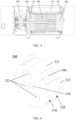
- FIG. 3 is a schematic diagram of a cross-sectional structure of the air conditioner shown in FIG. 1 .
- FIG. 4 is a schematic diagram of a three-dimensional structure of a first protective member in FIG. 3 .
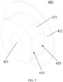
- FIG. 5 is a schematic diagram of a three-dimensional structure of a second protective member in FIG. 3 .
- FIG. 6 is a schematic diagram of a cross-sectional structure of an air conditioner according to another embodiment of the present disclosure.
- FIG. 7 is a schematic diagram of a cross-sectional structure of an air conditioner according to still another embodiment of the present disclosure.
- a blower includes: a volute 100; a wind wheel 200 rotatably mounted within the volute 100; and a flexible protective member.
- the protective member has a limiting section and a mounting section, the mounting section is detachably fixed at an air inlet of the volute 100, and the limiting section is inserted into an air inlet of the wind wheel 200 and is configured to prevent the wind wheel 200 from shaking in the radial direction.
- the mounting section of the protective member is detachably fixed at the air inlet of the volute 100, the limiting section of the protective member is inserted in the air inlet of the wind wheel 200.
- the blower is applied to an air conditioner, and when the air conditioner falls, the flexible protective member prevents the wind wheel 200 from shaking in the radial direction, effectively avoiding problems such as jamming and breaking of the wind wheel 200. After the air conditioner is mounted, the protective member can be detached, and the protective member will not affect the normal air intake of the blower.
- a radial distance between the limiting section and a circumferential wall of the air inlet of the wind wheel 200 is not more than 15 mm.
- the blower is applied to an air conditioner, and when the air conditioner falls, the flexible protective member can better prevent the wind wheel 200 from shaking in the radial direction, and the wind wheel 200 will not have problems such as jamming and breaking.
- the radial distance between the limiting section and the circumferential wall of the air inlet of the wind wheel 200 may be set to 5 mm. Alternatively, the radial distance between the limiting section and the circumferential wall of the air inlet of the wind wheel 200 may be set to 10 mm. Alternatively, the radial distance between the limiting section and the circumferential wall of the air inlet of the wind wheel 200 may be set to 15 mm or the like. All of the above can achieve the purpose of the present application, and the tenet thereof does not deviate from the design idea of the present disclosure, so it will not be repeated herein, and all of them should fall within the scope of protection of the present application.
- the volute 100 includes: a volute body 110, each of both end walls of the volute body 110 being provided with an opening; and two guide rings 120 mounted at two openings in one-to-one correspondence, the inside of the two guide rings 120 forming two air inlets of the volute 100.
- the two air inlets of the volute 100 include a first air inlet 111 and a second air inlet 112.
- the protective member includes a first protective member 300 and a second protective member 400.
- the first protective member 300 is disposed at the first air inlet 111
- the second protective member 400 is provided at the second air inlet 112.
- the structure of the first protective member 300 will be described in detail below.
- a shaft hole 330 is provided at a central axis of the first protective member 300, a side wall of the first protective member 300 is provided with an opening slit 340 that penetrates both axially and radially, a radial inner end of the opening slit 340 is communicated with the shaft hole 330, and a radial outer end of the opening slit 340 is communicated with the outside.
- the blower further includes a motor 500, the motor 500 is located outside the volute 100, a rotating shaft of the motor 500 is connected with the wind wheel 200, and the first protective member 300 is detachably fixed and sleeved on the rotating shaft of the motor 500 by means of the opening slit 340.
- the first protective member 300 is detached from the rotating shaft of the motor 500 by means of the opening slit 340, so that the first protective member 300 does not affect the normal air intake of the blower.
- the limiting section 310 of the first protective member 300 is inserted into one of the air inlets of the wind wheel 200.
- an outer circumferential surface of the mounting section 320 of the first protective member 300 is provided with a plurality of first bosses 321 at intervals, and boss surfaces of the plurality of first bosses 321 abut against an inner circumferential surface of the first air inlet 111 to ensure that the mounting section 320 and the inner circumferential surface of the first air inlet 111 will not detach spontaneously, and a friction force between the mounting section 320 and the inner circumferential surface of the first air inlet 111 is reduced, which is convenient for the operator to mount the first protective member 300 to the volute 100 and detach the first protective member 300 from the volute 100.
- the plurality of first bosses 321 are uniformly arranged along the circumferential direction so that the guide ring 120 is not squeezed and deformed.
- the blower is applied to an air conditioner, and when the air conditioner is dropped, a hole wall of the shaft hole 330 radially positions and supports the rotating shaft of the motor 500 to prevent the rotating shaft of the motor 500 from shaking in the radial direction, thus effectively preventing the wind wheel 200 from shaking in the radial direction.
- the plurality of first bosses 321 may be two first bosses 321. Alternatively, the plurality of first bosses 321 may be three first bosses 321. Alternatively, the plurality of first bosses 321 may be four first bosses 321 or the like. All of the above can achieve the purpose of the present application, and the tenet thereof does not deviate from the design idea of the present disclosure, so it will not be repeated herein, and all of them should fall within the scope of protection of the present application.
- a radial height of a first boss 321 is 2 mm to 6 mm.
- the radial height of the first boss 321 may be 2 mm.
- the radial height of the first boss 321 is 4 mm.
- the radial height of the first boss 321 may be 6 mm or the like. All of the above can achieve the purpose of the present application, and the tenet thereof does not deviate from the design idea of the present disclosure, so it will not be repeated herein, and all of them should fall within the scope of protection of the present application.
- the outer circumferential surface of the mounting section 320 of the first protective member 300 is further provided with a second boss 322.
- the second boss 322 is located outside the volute 100, and a side surface of the second boss 322 facing the volute 100 abuts against an outer end surface of the first air inlet 111 to prevent the first protective member 300 from completely entering the inside of the volute 100 from the first air inlet 111, the complete entering will result in loss of the protective function of the first protective member 300.
- the second boss 322 may be an annular boss.
- the second boss 322 may be a plurality of arc-shaped bosses or the like circumferentially arranged at intervals. All of the above can achieve the purpose of the present application, and the tenet thereof does not deviate from the design idea of the present disclosure, so it will not be repeated herein, and all of them should fall within the scope of protection of the present application.
- an end surface of the first protective member 300 facing the outside of the volute 100 is provided with a gripping portion 323, and the gripping portion 323 is provided for an operator to quickly detach and assemble the first protective member 300, thereby reducing the difficulty of operation.
- the gripping portion 323 includes a plurality of gripping holes, and the plurality of gripping holes are positioned alongside the shaft hole 330 and penetrate the first protective member 300 in the axial direction. Fingers may insert into the plurality of gripping holes to quickly remove the first protective member 300.
- the structure of the second protective member 400 will be described in detail below.
- an outer circumferential surface of the mounting section 420 of the second protective member 400 is provided with a plurality of first bosses 421 at intervals, and boss surfaces of the plurality of first bosses 421 abut against an inner circumferential surface of the second air inlet 112 to ensure that the mounting section 420 and the inner circumferential surface of the second air inlet 112 will not detach spontaneously, and a friction force between the mounting section 420 and the inner circumferential surface of the second air inlet 112 is reduced, which is convenient for the operator to mount the second protective member 400 to the volute 100 and detach the second protective member 400 from the volute 100.
- the plurality of first bosses 421 are uniformly arranged along the circumferential direction so that the guide ring 120 is not squeezed and deformed.
- the limiting section 410 of the second protective member 400 is inserted into another air inlet of the wind wheel 200.
- the plurality of first bosses 421 may be two first bosses 421. Alternatively, the plurality of first bosses 421 may be three first bosses 421. Alternatively, the plurality of first bosses 421 may be four first bosses 421 or the like. All of the above can achieve the purpose of the present application, and the tenet thereof does not deviate from the design idea of the present disclosure, so it will not be repeated herein, and all of them should fall within the scope of protection of the present application.
- a radial height of a first boss 421 is 2 mm to 6 mm.
- the radial height of the first boss 421 may be 2 mm.
- the radial height of the first boss 421 is 4 mm.
- the radial height of the first boss 421 may be 6 mm or the like. All of the above can achieve the purpose of the present application, and the tenet thereof does not deviate from the design idea of the present disclosure, so it will not be repeated herein, and all of them should fall within the scope of protection of the present application.
- the outer circumferential surface of the mounting section 420 of the second protective member 400 is further provided with a second boss 422.
- the second boss 422 is located outside the volute 100, and a side surface of the second boss 422 facing the volute 100 abuts against an outer end surface of the second air inlet 112 to prevent the second protective member 400 from completely entering the inside of the volute 100 from the second air inlet 112, the complete entering will result in loss of the protective function of the second protective member 400.
- the second boss 422 may be an annular boss.
- the second boss 422 includes a plurality of arc-shaped bosses or the like circumferentially arranged at intervals. All of the above can achieve the purpose of the present application, and the tenet thereof does not deviate from the design idea of the present disclosure, so it will not be repeated herein, and all of them should fall within the scope of protection of the present application.
- an end surface of the second protective member 400 facing the outside of the volute 100 is provided with a gripping portion 423, and the gripping portion 423 is provided for an operator to quickly detach and assemble the second protective member 400, thereby reducing the difficulty of operation.
- the gripping portion 423 includes a gripping hole provided at a central axis of the second protective member 400, and the gripping hole penetrates the second protective member 400 in the axial direction. A finger may insert into the gripping hole to quickly remove the second protective member 400.
- only the first air inlet 111 is mounted with the first protective member 300.
- only the second air inlet 112 is mounted with the second protective member 400. All of the above can achieve the purpose of the present application, and the tenet thereof does not deviate from the design idea of the present disclosure, so it will not be repeated herein, and all of them should fall within the scope of protection of the present application.
- the air conditioner according to an embodiment of the present disclosure includes the blower described in any of the above embodiments.
- the air conditioner has all the advantages of the blower according to any one of the above-described embodiments, which will not be repeatedly described herein.
- the mounting section of the protective member is detachably fixed at the air inlet of the volute, and the limiting section of the protective member is inserted in the air inlet of the wind wheel.
- the blower is applied to an air conditioner, and when the air conditioner falls, the flexible protective member prevents the wind wheel from shaking in the radial direction, effectively avoiding problems such as jamming and breaking of the wind wheel. After the air conditioner is mounted, the protective member can be detached, and the protective member will not affect the normal air intake of the blower.
Landscapes
- Engineering & Computer Science (AREA)
- Mechanical Engineering (AREA)
- General Engineering & Computer Science (AREA)
- Chemical & Material Sciences (AREA)
- Combustion & Propulsion (AREA)
- Structures Of Non-Positive Displacement Pumps (AREA)
Abstract
Description
- The present application claims priority to a
Chinese patent application filed to CNIPA on August 23, 2022 with application number 2022110138686 - The present disclosure relates to, but is not limited to, the field of electrical device, and particularly relates to a blower and an air conditioner.
- The blower of an indoor unit of the related air conditioner includes a motor, a wind wheel and a volute. The volute includes a volute body and a guide ring mounted on the volute body. The motor is positioned on a left or right side of the volute, the wind wheel is positioned in the volute and mounted on a rotating shaft of the motor, and the wind wheel forms a cantilever structure. During the falling process of the whole machine, a radial shaking stroke of the wind wheel is large, and the wind wheel collides with a circumferential wall of the volute body and the guide ring, causing problems such as jamming and breaking of the wind wheel.
- The following is a summary of the subject matter described in detail herein. This summary is not intended to limit the protection scope of the claims.
- A blower according to an embodiment of the present disclosure includes: a volute; a wind wheel rotatably mounted within the volute; and a flexible protective member having a limiting section and a mounting section. The mounting section is detachably fixed at an air inlet of the volute, and the limiting section is inserted into an air inlet of the wind wheel and is configured to prevent the wind wheel from shaking in the radial direction.
- In some exemplary embodiments, a radial distance between the limiting section and a circumferential wall of the air inlet of the wind wheel is not greater than 15 mm.
- In some exemplary embodiments, an outer circumferential surface of the mounting section is provided with a plurality of first bosses at intervals, and boss surfaces of the plurality of first bosses abut against an inner circumferential surface of the air inlet of the volute.
- In some exemplary embodiments, a radial height of a first boss is 2 mm to 6 mm.
- In some exemplary embodiments, the outer circumferential surface of the mounting segment is provided with a second boss located outside the volute, and a side surface of the second boss facing the volute abuts against an outer end surface of the air inlet of the volute.
- In some exemplary embodiments, the second boss includes an annular boss.
- In some exemplary embodiments, the second boss includes a plurality of arc-shaped bosses circumferentially arranged at intervals.
- In some exemplary embodiments, an end surface of the protective member facing the outside of the volute is provided with a gripping portion, and the gripping portion is configured for an operator to assemble and detach the protective member.
- In some exemplary embodiments, the gripping portion includes one or more gripping holes.
- In some exemplary embodiments, the volute includes: a volute body, an end surface of the volute body being provided with an opening; and a guide ring mounted at the opening, the inside of the guide ring forming the air inlet of the volute.
- In some exemplary embodiments, the protective member includes a first protective member and a second protective member, the air inlet of the volute includes a first air inlet and a second air inlet, the first protective member is disposed at the first air inlet, and the second protective member is disposed at the second air inlet.
- In some exemplary embodiments, a shaft hole is provided at a central axis of the first protective member, a side wall of the first protective member is provided with an opening slit that penetrates both axially and radially, and a radial inner end of the opening slit is communicated with the shaft hole, and a radial outer end of the opening slit is communicated with the outside. The blower further includes a motor located outside the volute, a rotating shaft of the motor is connected with the wind wheel, and the first protective member is detachably fixed and sleeved on the rotating shaft of the motor by means of the opening slit.
- In some exemplary embodiments, a shaft hole is provided at a central axis of the protective member, a side wall of the protective member is provided with an opening slit that penetrates both axially and radially, and a radial inner end of the opening slit is communicated with the shaft hole, and a radial outer end of the opening slit is communicated with the outside. The blower further includes a motor located outside the volute, a rotating shaft of the motor is connected with the wind wheel, and the protective member is detachably fixed and sleeved on the rotating shaft of the motor by means of the opening slit.
- An air conditioner according to an embodiment of the present disclosure includes the blower according to any one of the above embodiments.
- The following is a summary of the subject matter described in detail herein. This summary is not intended to limit the protection scope of the claims.
-
-
FIG. 1 is a schematic diagram of a three-dimensional structure of an air conditioner from one perspective according to some embodiments of the present disclosure. -
FIG. 2 is a schematic diagram of a three-dimensional structure of the air conditioner shown inFIG. 1 from another perspective. -
FIG. 3 is a schematic diagram of a cross-sectional structure of the air conditioner shown inFIG. 1 . -
FIG. 4 is a schematic diagram of a three-dimensional structure of a first protective member inFIG. 3 . -
FIG. 5 is a schematic diagram of a three-dimensional structure of a second protective member inFIG. 3 . -
FIG. 6 is a schematic diagram of a cross-sectional structure of an air conditioner according to some other embodiments of the present disclosure. -
FIG. 7 is a schematic diagram of a cross-sectional structure of an air conditioner according to still some embodiments of the present disclosure. - The relationship between reference signs and component names in
FIG. 1 to FIG. 7 is as follows:
100 volute, 110 volute body, 111 first air inlet, 112 second air inlet, 120 guide ring, 200 wind wheel, 300 first protective member, 310 limiting section, 320 mounting section, 321 first boss, 322 second boss, 323 gripping portion, 330 shaft hole, 340 opening slit, 400 second protective member, 410 limiting section, 420 mounting section, 421 first boss, 422 second boss, 423 gripping portion, 500 motor. - A clear and complete description of the technical schemes of the embodiments of the present disclosure will be given below in conjunction with the accompanying drawings in the embodiments of the present disclosure. It will be apparent that the described embodiments are only a part, rather than all, of the embodiments of the present disclosure. Based on the embodiments in the present disclosure, all other embodiments obtained without paying creative effort by those of ordinary skill in the art fall within the scope of protection of the present disclosure.
- It should be noted that all directivity indications (such as up, down, left, right, front, back, etc.) in the embodiments of the present disclosure are only used to explain a relative positional relationship, a motion situation, etc., among various components under a specific posture (as shown in the accompanying drawings), and if the specific posture changes, the directivity indications will change accordingly.
- In addition, descriptions such as those relating to "first", "second" and the like in the present disclosure are intended for descriptive purposes only and cannot be construed as indicating or implying their relative importance or implying the number of technical features indicated. Thus, the features defined with "first" or "second" may explicitly or implicitly include at least one of the features. In the description of the present disclosure, "a plurality of/multiple" means at least two, e.g., two, three, and the like, unless explicitly and specifically defined otherwise.
- In the present disclosure, the terms "mounting", "join", "connection", "fixation" and the like should be understood in a broad sense unless otherwise expressly specified and limited. For example, "fixation" may be a fixed connection, may be a detachable connection, or may be an integrated connection; may be a mechanical connection or an electrical connection. "Connection" may be a direct connection or an indirect connection through an intermediate medium, or may be an internal connection between two elements or an interactive relationship between two elements, unless otherwise expressly defined. For those of ordinary skills in the art, the specific meanings of the above terms in the present disclosure can be understood according to specific situations.
- In addition, the technical solutions in the various embodiments of the present disclosure may be combined with each other, but it is needed to be on the basis that the person of ordinary skill in the art can realize it. When the combination of technical solutions is contradictory or impossible to realize, it should be considered that such combination of technical solutions does not exist and is not within the scope of protection claimed by the present disclosure.
- A main object of the present disclosure is to provide a blower capable of avoiding jamming and breaking of a wind wheel.
- A main object of the present disclosure is to also provide an air conditioner.
-
FIG. 1 is a three-dimensional structural schematic diagram of an air conditioner according to an embodiment of the present disclosure from one perspective.FIG. 2 is a schematic diagram of a three-dimensional structure of the air conditioner shown inFIG. 1 from another perspective.FIG. 3 is a schematic diagram of a cross-sectional structure of the air conditioner shown inFIG. 1 .FIG. 4 is a schematic diagram of a three-dimensional structure of a first protective member inFIG. 3 .FIG. 5 is a schematic diagram of a three-dimensional structure of a second protective member inFIG. 3 .FIG. 6 is a schematic diagram of a cross-sectional structure of an air conditioner according to another embodiment of the present disclosure.FIG. 7 is a schematic diagram of a cross-sectional structure of an air conditioner according to still another embodiment of the present disclosure. - As shown in
FIGS. 1 to 3 ,6 and 7 , a blower according to an embodiment of the present disclosure includes: avolute 100; awind wheel 200 rotatably mounted within thevolute 100; and a flexible protective member. The protective member has a limiting section and a mounting section, the mounting section is detachably fixed at an air inlet of thevolute 100, and the limiting section is inserted into an air inlet of thewind wheel 200 and is configured to prevent thewind wheel 200 from shaking in the radial direction. - In the blower, the mounting section of the protective member is detachably fixed at the air inlet of the
volute 100, the limiting section of the protective member is inserted in the air inlet of thewind wheel 200. The blower is applied to an air conditioner, and when the air conditioner falls, the flexible protective member prevents thewind wheel 200 from shaking in the radial direction, effectively avoiding problems such as jamming and breaking of thewind wheel 200. After the air conditioner is mounted, the protective member can be detached, and the protective member will not affect the normal air intake of the blower. - In some exemplary embodiments, as shown in
FIGS. 3 ,6, and 7 , a radial distance between the limiting section and a circumferential wall of the air inlet of thewind wheel 200 is not more than 15 mm. The blower is applied to an air conditioner, and when the air conditioner falls, the flexible protective member can better prevent thewind wheel 200 from shaking in the radial direction, and thewind wheel 200 will not have problems such as jamming and breaking. - The radial distance between the limiting section and the circumferential wall of the air inlet of the
wind wheel 200 may be set to 5 mm. Alternatively, the radial distance between the limiting section and the circumferential wall of the air inlet of thewind wheel 200 may be set to 10 mm. Alternatively, the radial distance between the limiting section and the circumferential wall of the air inlet of thewind wheel 200 may be set to 15 mm or the like. All of the above can achieve the purpose of the present application, and the tenet thereof does not deviate from the design idea of the present disclosure, so it will not be repeated herein, and all of them should fall within the scope of protection of the present application. - In some exemplary embodiments, as shown in
FIG. 3 , thevolute 100 includes: avolute body 110, each of both end walls of thevolute body 110 being provided with an opening; and two guide rings 120 mounted at two openings in one-to-one correspondence, the inside of the two guide rings 120 forming two air inlets of thevolute 100. The two air inlets of thevolute 100 include afirst air inlet 111 and asecond air inlet 112. As shown inFIGS. 1 to 5 , the protective member includes a firstprotective member 300 and a secondprotective member 400. The firstprotective member 300 is disposed at thefirst air inlet 111, and the secondprotective member 400 is provided at thesecond air inlet 112. By limiting both ends of thewind wheel 200 through the firstprotective member 300 and the secondprotective member 400, it is possible to better prevent thewind wheel 200 from shaking in the radial direction. - The structure of the first
protective member 300 will be described in detail below. - In some examples, as shown in
FIG. 4 , ashaft hole 330 is provided at a central axis of the firstprotective member 300, a side wall of the firstprotective member 300 is provided with anopening slit 340 that penetrates both axially and radially, a radial inner end of theopening slit 340 is communicated with theshaft hole 330, and a radial outer end of theopening slit 340 is communicated with the outside. The blower further includes amotor 500, themotor 500 is located outside thevolute 100, a rotating shaft of themotor 500 is connected with thewind wheel 200, and the firstprotective member 300 is detachably fixed and sleeved on the rotating shaft of themotor 500 by means of theopening slit 340. After the air conditioner is mounted, the firstprotective member 300 is detached from the rotating shaft of themotor 500 by means of theopening slit 340, so that the firstprotective member 300 does not affect the normal air intake of the blower. The limitingsection 310 of the firstprotective member 300 is inserted into one of the air inlets of thewind wheel 200. - In some examples, as shown in
FIG. 4 , an outer circumferential surface of the mountingsection 320 of the firstprotective member 300 is provided with a plurality offirst bosses 321 at intervals, and boss surfaces of the plurality offirst bosses 321 abut against an inner circumferential surface of thefirst air inlet 111 to ensure that the mountingsection 320 and the inner circumferential surface of thefirst air inlet 111 will not detach spontaneously, and a friction force between the mountingsection 320 and the inner circumferential surface of thefirst air inlet 111 is reduced, which is convenient for the operator to mount the firstprotective member 300 to thevolute 100 and detach the firstprotective member 300 from thevolute 100. The plurality offirst bosses 321 are uniformly arranged along the circumferential direction so that theguide ring 120 is not squeezed and deformed. - Furthermore, the blower is applied to an air conditioner, and when the air conditioner is dropped, a hole wall of the
shaft hole 330 radially positions and supports the rotating shaft of themotor 500 to prevent the rotating shaft of themotor 500 from shaking in the radial direction, thus effectively preventing thewind wheel 200 from shaking in the radial direction. - The plurality of
first bosses 321 may be twofirst bosses 321. Alternatively, the plurality offirst bosses 321 may be threefirst bosses 321. Alternatively, the plurality offirst bosses 321 may be fourfirst bosses 321 or the like. All of the above can achieve the purpose of the present application, and the tenet thereof does not deviate from the design idea of the present disclosure, so it will not be repeated herein, and all of them should fall within the scope of protection of the present application. - In some embodiments, a radial height of a
first boss 321 is 2 mm to 6 mm. The radial height of thefirst boss 321 may be 2 mm. Alternatively, the radial height of thefirst boss 321 is 4 mm. Alternatively, the radial height of thefirst boss 321 may be 6 mm or the like. All of the above can achieve the purpose of the present application, and the tenet thereof does not deviate from the design idea of the present disclosure, so it will not be repeated herein, and all of them should fall within the scope of protection of the present application. - In some examples, as shown in
FIG. 4 , the outer circumferential surface of the mountingsection 320 of the firstprotective member 300 is further provided with asecond boss 322. Thesecond boss 322 is located outside thevolute 100, and a side surface of thesecond boss 322 facing thevolute 100 abuts against an outer end surface of thefirst air inlet 111 to prevent the firstprotective member 300 from completely entering the inside of the volute 100 from thefirst air inlet 111, the complete entering will result in loss of the protective function of the firstprotective member 300. - The
second boss 322 may be an annular boss. Alternatively, thesecond boss 322 may be a plurality of arc-shaped bosses or the like circumferentially arranged at intervals. All of the above can achieve the purpose of the present application, and the tenet thereof does not deviate from the design idea of the present disclosure, so it will not be repeated herein, and all of them should fall within the scope of protection of the present application. - In some examples, as shown in
FIG. 4 , an end surface of the firstprotective member 300 facing the outside of thevolute 100 is provided with agripping portion 323, and thegripping portion 323 is provided for an operator to quickly detach and assemble the firstprotective member 300, thereby reducing the difficulty of operation. - In some embodiments, as shown in
FIG. 4 , the grippingportion 323 includes a plurality of gripping holes, and the plurality of gripping holes are positioned alongside theshaft hole 330 and penetrate the firstprotective member 300 in the axial direction. Fingers may insert into the plurality of gripping holes to quickly remove the firstprotective member 300. - The structure of the second
protective member 400 will be described in detail below. - In some examples, as shown in
FIG. 5 , an outer circumferential surface of the mountingsection 420 of the secondprotective member 400 is provided with a plurality offirst bosses 421 at intervals, and boss surfaces of the plurality offirst bosses 421 abut against an inner circumferential surface of thesecond air inlet 112 to ensure that the mountingsection 420 and the inner circumferential surface of thesecond air inlet 112 will not detach spontaneously, and a friction force between the mountingsection 420 and the inner circumferential surface of thesecond air inlet 112 is reduced, which is convenient for the operator to mount the secondprotective member 400 to thevolute 100 and detach the secondprotective member 400 from thevolute 100. The plurality offirst bosses 421 are uniformly arranged along the circumferential direction so that theguide ring 120 is not squeezed and deformed. The limitingsection 410 of the secondprotective member 400 is inserted into another air inlet of thewind wheel 200. - The plurality of
first bosses 421 may be twofirst bosses 421. Alternatively, the plurality offirst bosses 421 may be threefirst bosses 421. Alternatively, the plurality offirst bosses 421 may be fourfirst bosses 421 or the like. All of the above can achieve the purpose of the present application, and the tenet thereof does not deviate from the design idea of the present disclosure, so it will not be repeated herein, and all of them should fall within the scope of protection of the present application. - In some embodiments, a radial height of a
first boss 421 is 2 mm to 6 mm. The radial height of thefirst boss 421 may be 2 mm. Alternatively, the radial height of thefirst boss 421 is 4 mm. Alternatively, the radial height of thefirst boss 421 may be 6 mm or the like. All of the above can achieve the purpose of the present application, and the tenet thereof does not deviate from the design idea of the present disclosure, so it will not be repeated herein, and all of them should fall within the scope of protection of the present application. - In some examples, as shown in
FIG. 5 , the outer circumferential surface of the mountingsection 420 of the secondprotective member 400 is further provided with asecond boss 422. Thesecond boss 422 is located outside thevolute 100, and a side surface of thesecond boss 422 facing thevolute 100 abuts against an outer end surface of thesecond air inlet 112 to prevent the secondprotective member 400 from completely entering the inside of the volute 100 from thesecond air inlet 112, the complete entering will result in loss of the protective function of the secondprotective member 400. - The
second boss 422 may be an annular boss. Alternatively, thesecond boss 422 includes a plurality of arc-shaped bosses or the like circumferentially arranged at intervals. All of the above can achieve the purpose of the present application, and the tenet thereof does not deviate from the design idea of the present disclosure, so it will not be repeated herein, and all of them should fall within the scope of protection of the present application. - In some examples, as shown in
FIG. 5 , an end surface of the secondprotective member 400 facing the outside of thevolute 100 is provided with agripping portion 423, and thegripping portion 423 is provided for an operator to quickly detach and assemble the secondprotective member 400, thereby reducing the difficulty of operation. - In some embodiments, as shown in
FIG. 5 , the grippingportion 423 includes a gripping hole provided at a central axis of the secondprotective member 400, and the gripping hole penetrates the secondprotective member 400 in the axial direction. A finger may insert into the gripping hole to quickly remove the secondprotective member 400. - Alternatively, as shown in
FIG. 6 , only thefirst air inlet 111 is mounted with the firstprotective member 300. Alternatively, as shown inFIG. 7 , only thesecond air inlet 112 is mounted with the secondprotective member 400. All of the above can achieve the purpose of the present application, and the tenet thereof does not deviate from the design idea of the present disclosure, so it will not be repeated herein, and all of them should fall within the scope of protection of the present application. - As shown in
FIGS. 1 to 3 ,6, and 7 , the air conditioner according to an embodiment of the present disclosure includes the blower described in any of the above embodiments. - The air conditioner has all the advantages of the blower according to any one of the above-described embodiments, which will not be repeatedly described herein.
- To sum up, in the technical schemes of the present disclosure, the mounting section of the protective member is detachably fixed at the air inlet of the volute, and the limiting section of the protective member is inserted in the air inlet of the wind wheel. The blower is applied to an air conditioner, and when the air conditioner falls, the flexible protective member prevents the wind wheel from shaking in the radial direction, effectively avoiding problems such as jamming and breaking of the wind wheel. After the air conditioner is mounted, the protective member can be detached, and the protective member will not affect the normal air intake of the blower.
- Although implementations disclosed in the present disclosure are described above, the described contents are only implementations used for facilitating understanding of the present disclosure, and are not intended to limit the present disclosure. Without departing from the spirit and scope disclosed in the present disclosure, any person skilled in the art to which the present disclosure pertains may make any modifications and changes in the form and details of implementation, but the scope of patent protection of the present disclosure shall still be defined by the appended claims.
- The above descriptions are only optional embodiments of the present disclosure, and therefore do not limit the patent scope of the present disclosure. Equivalent structural transformation made by using the contents of the description and drawings of the present disclosure, or direct/indirect application in other related technical fields, within the concept of the present disclosure, is included in the patent protection scope of the present disclosure.
Claims (13)
- A blower, comprising:a volute;a wind wheel rotatably mounted within the volute; anda flexible protective member having a limiting section and an mounting section, wherein the mounting section is detachably fixed at an air inlet of the volute, and the limiting section is inserted into an air inlet of the wind wheel and is configured to prevent the wind wheel from shaking in a radial direction.
- The blower according to claim 1, wherein a radial distance between the limiting section and a circumferential wall of the air inlet of the wind wheel is not greater than 15 mm.
- The blower according to claim 1, wherein an outer circumferential surface of the mounting section is provided with a plurality of first bosses at intervals, and boss surfaces of the plurality of first bosses abut against an inner circumferential surface of the air inlet of the volute.
- The blower according to claim 3, wherein a radial height of a first boss is 2 mm to 6 mm.
- The blower according to claim 1, wherein an outer circumferential surface of the mounting section is provided with a second boss located outside the volute, and a side surface of the second boss facing the volute abuts against an outer end surface of the air inlet of the volute.
- The blower according to claim 5, wherein the second boss comprises an annular boss; or the second boss comprises a plurality of arc-shaped bosses circumferentially arranged at intervals.
- The blower according to claim 1, wherein an end surface of the protective member facing the outside of the volute is provided with a gripping portion configured for an operator to assemble and detach the protective member.
- The blower according to claim 7, wherein the gripping portion comprises one or more gripping holes.
- The blower according to claim 1, wherein the volute comprises:a volute body, an end surface of the volute body being provided with an opening; anda guide ring mounted at the opening, wherein an inside of the guide ring forms the air inlet of the volute.
- The blower according to any one of claims 1 to 9, wherein the protective member comprises a first protective member and a second protective member, the air inlet of the volute comprises a first air inlet and a second air inlet, the first protective member is disposed at the first air inlet, and the second protective member is disposed at the second air inlet.
- The blower according to claim 10, wherein a shaft hole is provided at a central axis of the first protective member, a side wall of the first protective member is provided with an opening slit that penetrates both axially and radially, and a radial inner end of the opening slit is communicated with the shaft hole, and a radial outer end of the opening slit is communicated with the outside; the blower further comprises:
a motor positioned outside the volute, wherein a rotating shaft of the motor is connected with the wind wheel, and the first protective member is detachably fixed and sleeved on the rotating shaft of the motor by means of the opening slit. - The blower according to any one of claims 1 to 9, wherein a shaft hole is provided at a central axis of the protective member, and a side wall of the protective member is provided with an opening slit that penetrates both axially and radially, a radial inner end of the opening slit is communicated with the shaft hole, and a radial outer end of the opening slit is communicated with the outside; the blower further comprises:
a motor positioned outside the volute, wherein a rotating shaft of the motor is connected with the wind wheel, and the protective member is detachably fixed and sleeved on the rotating shaft of the motor by means of the opening slit. - An air conditioner comprising a blower according to any one of claims 1 to 12.
Applications Claiming Priority (2)
| Application Number | Priority Date | Filing Date | Title |
|---|---|---|---|
| CN202211013868.6A CN117663253A (en) | 2022-08-23 | 2022-08-23 | Fans and air conditioners |
| PCT/CN2023/099511 WO2024041104A1 (en) | 2022-08-23 | 2023-06-09 | Blower and air conditioner |
Publications (2)
| Publication Number | Publication Date |
|---|---|
| EP4484839A1 true EP4484839A1 (en) | 2025-01-01 |
| EP4484839A4 EP4484839A4 (en) | 2025-07-30 |
Family
ID=90012345
Family Applications (1)
| Application Number | Title | Priority Date | Filing Date |
|---|---|---|---|
| EP23856196.3A Pending EP4484839A4 (en) | 2022-08-23 | 2023-06-09 | BLOWER AND AIR CONDITIONING |
Country Status (5)
| Country | Link |
|---|---|
| US (1) | US12359679B1 (en) |
| EP (1) | EP4484839A4 (en) |
| KR (1) | KR20240151219A (en) |
| CN (1) | CN117663253A (en) |
| WO (1) | WO2024041104A1 (en) |
Family Cites Families (14)
| Publication number | Priority date | Publication date | Assignee | Title |
|---|---|---|---|---|
| FR2801941B1 (en) | 1999-12-06 | 2002-02-08 | Valeo Climatisation | HEATING-AIR CONDITIONING SYSTEM COMPRISING AT LEAST ONE CENTRIFUGAL PULSE |
| JP5269060B2 (en) * | 2010-12-24 | 2013-08-21 | 三菱電機株式会社 | Cross-flow fan and air conditioner indoor unit |
| CN202391815U (en) * | 2011-12-03 | 2012-08-22 | 中山大洋电机股份有限公司 | A sealing structure of induced draft fan volute |
| CN203641081U (en) | 2013-11-27 | 2014-06-11 | 魏国宏 | Shock-proof and sealed connecting structure of blower |
| CN104612987B (en) | 2014-12-26 | 2017-07-07 | 广东美的制冷设备有限公司 | Blower fan and air-conditioner |
| CN204692124U (en) | 2015-03-20 | 2015-10-07 | 大金工业株式会社 | Blast device assembly and there is the airhandling equipment of this blast device assembly |
| US10634168B2 (en) * | 2015-10-07 | 2020-04-28 | Mitsubishi Electric Corporation | Blower and air-conditioning apparatus including the same |
| JP6551173B2 (en) * | 2015-11-09 | 2019-07-31 | 株式会社デンソー | Centrifugal blower |
| CN107701518B (en) * | 2017-10-19 | 2024-03-29 | 珠海格力电器股份有限公司 | Cross-flow wind wheel mounting structure, air duct assembly and device with cross-flow wind wheel |
| CN110594202A (en) | 2019-10-29 | 2019-12-20 | 浙江科贸实业有限公司 | Vibration-proof pad of ventilator |
| CN111425415B (en) | 2020-04-02 | 2025-08-19 | 长沙洛丹青环保科技有限公司 | Fan |
| CN212202545U (en) | 2020-04-27 | 2020-12-22 | 浙江炬光汽车零部件有限公司 | Blower with vibration-proof gear |
| CN215170919U (en) | 2021-04-25 | 2021-12-14 | 美的集团武汉暖通设备有限公司 | Fan components and duct machines |
| CN217979022U (en) | 2022-08-23 | 2022-12-06 | 广东美的暖通设备有限公司 | Fan and air conditioner |
-
2022
- 2022-08-23 CN CN202211013868.6A patent/CN117663253A/en active Pending
-
2023
- 2023-06-09 US US18/848,781 patent/US12359679B1/en active Active
- 2023-06-09 EP EP23856196.3A patent/EP4484839A4/en active Pending
- 2023-06-09 KR KR1020247031009A patent/KR20240151219A/en not_active Withdrawn
- 2023-06-09 WO PCT/CN2023/099511 patent/WO2024041104A1/en not_active Ceased
Also Published As
| Publication number | Publication date |
|---|---|
| WO2024041104A1 (en) | 2024-02-29 |
| US12359679B1 (en) | 2025-07-15 |
| US20250230821A1 (en) | 2025-07-17 |
| CN117663253A (en) | 2024-03-08 |
| KR20240151219A (en) | 2024-10-17 |
| EP4484839A4 (en) | 2025-07-30 |
Similar Documents
| Publication | Publication Date | Title |
|---|---|---|
| US6612817B2 (en) | Serial fan | |
| US5133617A (en) | Motor mount assembly | |
| EP1845603B1 (en) | Axial fan motor | |
| US6045112A (en) | Vibration isolation system for an electric motor | |
| EP3133292B1 (en) | Axial blower and series-type axial blower | |
| EP3168519A1 (en) | Fast cradle head inserting device and aircraft | |
| WO2012012547A1 (en) | Blower assembly with motor integrated into the impeller fan and blower housing constructions | |
| US20140356149A1 (en) | Fan | |
| US7329100B2 (en) | Centrifugal fan impeller | |
| JP2019180195A (en) | Motor and centrifugal fan | |
| US20240392807A1 (en) | Diagonal fan | |
| US12359679B1 (en) | Blower and air conditioner | |
| EP2885502A1 (en) | Blower motor assembly having air directing surface | |
| WO2024051358A1 (en) | Motor damping structure, motor and electrical device | |
| CN112994321B (en) | Motor end cover, motor and unmanned aerial vehicle | |
| JP7179609B2 (en) | axial fan | |
| KR20250133711A (en) | Bladeless fan lamp | |
| CN217979022U (en) | Fan and air conditioner | |
| EP3453886A1 (en) | Ceiling fan | |
| CN209761776U (en) | Fan with cooling device | |
| WO2020138678A1 (en) | Fan motor | |
| EP4155548A1 (en) | Axial fan | |
| CN213514094U (en) | Air conditioner indoor unit and air conditioner with same | |
| CN110762628B (en) | Motor support and air conditioner | |
| US20190120251A1 (en) | Blower assembly and methods of assembling the same |
Legal Events
| Date | Code | Title | Description |
|---|---|---|---|
| STAA | Information on the status of an ep patent application or granted ep patent |
Free format text: STATUS: THE INTERNATIONAL PUBLICATION HAS BEEN MADE |
|
| PUAI | Public reference made under article 153(3) epc to a published international application that has entered the european phase |
Free format text: ORIGINAL CODE: 0009012 |
|
| STAA | Information on the status of an ep patent application or granted ep patent |
Free format text: STATUS: REQUEST FOR EXAMINATION WAS MADE |
|
| 17P | Request for examination filed |
Effective date: 20240925 |
|
| AK | Designated contracting states |
Kind code of ref document: A1 Designated state(s): AL AT BE BG CH CY CZ DE DK EE ES FI FR GB GR HR HU IE IS IT LI LT LU LV MC ME MK MT NL NO PL PT RO RS SE SI SK SM TR |
|
| REG | Reference to a national code |
Ref country code: DE Ref legal event code: R079 Free format text: PREVIOUS MAIN CLASS: F24F0011000000 Ipc: F04D0025080000 |
|
| A4 | Supplementary search report drawn up and despatched |
Effective date: 20250701 |
|
| RIC1 | Information provided on ipc code assigned before grant |
Ipc: F04D 25/08 20060101AFI20250625BHEP Ipc: F04D 29/66 20060101ALI20250625BHEP Ipc: F24F 11/00 20180101ALI20250625BHEP |
|
| DAV | Request for validation of the european patent (deleted) | ||
| DAX | Request for extension of the european patent (deleted) | ||
| STAA | Information on the status of an ep patent application or granted ep patent |
Free format text: STATUS: THE APPLICATION IS DEEMED TO BE WITHDRAWN |