EP4484837A1 - Air conditioning apparatus - Google Patents
Air conditioning apparatus Download PDFInfo
- Publication number
- EP4484837A1 EP4484837A1 EP23859040.0A EP23859040A EP4484837A1 EP 4484837 A1 EP4484837 A1 EP 4484837A1 EP 23859040 A EP23859040 A EP 23859040A EP 4484837 A1 EP4484837 A1 EP 4484837A1
- Authority
- EP
- European Patent Office
- Prior art keywords
- box body
- connection base
- heat exchanger
- air conditioning
- conditioning apparatus
- Prior art date
- Legal status (The legal status is an assumption and is not a legal conclusion. Google has not performed a legal analysis and makes no representation as to the accuracy of the status listed.)
- Pending
Links
Images











Classifications
-
- F—MECHANICAL ENGINEERING; LIGHTING; HEATING; WEAPONS; BLASTING
- F24—HEATING; RANGES; VENTILATING
- F24F—AIR-CONDITIONING; AIR-HUMIDIFICATION; VENTILATION; USE OF AIR CURRENTS FOR SCREENING
- F24F11/00—Control or safety arrangements
- F24F11/89—Arrangement or mounting of control or safety devices
-
- F—MECHANICAL ENGINEERING; LIGHTING; HEATING; WEAPONS; BLASTING
- F24—HEATING; RANGES; VENTILATING
- F24F—AIR-CONDITIONING; AIR-HUMIDIFICATION; VENTILATION; USE OF AIR CURRENTS FOR SCREENING
- F24F1/00—Room units for air-conditioning, e.g. separate or self-contained units or units receiving primary air from a central station
- F24F1/06—Separate outdoor units, e.g. outdoor unit to be linked to a separate room comprising a compressor and a heat exchanger
- F24F1/14—Heat exchangers specially adapted for separate outdoor units
- F24F1/16—Arrangement or mounting thereof
-
- F—MECHANICAL ENGINEERING; LIGHTING; HEATING; WEAPONS; BLASTING
- F24—HEATING; RANGES; VENTILATING
- F24F—AIR-CONDITIONING; AIR-HUMIDIFICATION; VENTILATION; USE OF AIR CURRENTS FOR SCREENING
- F24F1/00—Room units for air-conditioning, e.g. separate or self-contained units or units receiving primary air from a central station
- F24F1/06—Separate outdoor units, e.g. outdoor unit to be linked to a separate room comprising a compressor and a heat exchanger
- F24F1/20—Electric components for separate outdoor units
- F24F1/22—Arrangement or mounting thereof
-
- F—MECHANICAL ENGINEERING; LIGHTING; HEATING; WEAPONS; BLASTING
- F24—HEATING; RANGES; VENTILATING
- F24F—AIR-CONDITIONING; AIR-HUMIDIFICATION; VENTILATION; USE OF AIR CURRENTS FOR SCREENING
- F24F1/00—Room units for air-conditioning, e.g. separate or self-contained units or units receiving primary air from a central station
- F24F1/06—Separate outdoor units, e.g. outdoor unit to be linked to a separate room comprising a compressor and a heat exchanger
- F24F1/20—Electric components for separate outdoor units
- F24F1/24—Cooling of electric components
-
- F—MECHANICAL ENGINEERING; LIGHTING; HEATING; WEAPONS; BLASTING
- F24—HEATING; RANGES; VENTILATING
- F24F—AIR-CONDITIONING; AIR-HUMIDIFICATION; VENTILATION; USE OF AIR CURRENTS FOR SCREENING
- F24F1/00—Room units for air-conditioning, e.g. separate or self-contained units or units receiving primary air from a central station
- F24F1/06—Separate outdoor units, e.g. outdoor unit to be linked to a separate room comprising a compressor and a heat exchanger
- F24F1/38—Fan details of outdoor units, e.g. bell-mouth shaped inlets or fan mountings
-
- F—MECHANICAL ENGINEERING; LIGHTING; HEATING; WEAPONS; BLASTING
- F24—HEATING; RANGES; VENTILATING
- F24F—AIR-CONDITIONING; AIR-HUMIDIFICATION; VENTILATION; USE OF AIR CURRENTS FOR SCREENING
- F24F1/00—Room units for air-conditioning, e.g. separate or self-contained units or units receiving primary air from a central station
- F24F1/06—Separate outdoor units, e.g. outdoor unit to be linked to a separate room comprising a compressor and a heat exchanger
- F24F1/46—Component arrangements in separate outdoor units
- F24F1/48—Component arrangements in separate outdoor units characterised by air airflow, e.g. inlet or outlet airflow
-
- F—MECHANICAL ENGINEERING; LIGHTING; HEATING; WEAPONS; BLASTING
- F24—HEATING; RANGES; VENTILATING
- F24F—AIR-CONDITIONING; AIR-HUMIDIFICATION; VENTILATION; USE OF AIR CURRENTS FOR SCREENING
- F24F1/00—Room units for air-conditioning, e.g. separate or self-contained units or units receiving primary air from a central station
- F24F1/06—Separate outdoor units, e.g. outdoor unit to be linked to a separate room comprising a compressor and a heat exchanger
- F24F1/56—Casing or covers of separate outdoor units, e.g. fan guards
-
- F—MECHANICAL ENGINEERING; LIGHTING; HEATING; WEAPONS; BLASTING
- F24—HEATING; RANGES; VENTILATING
- F24F—AIR-CONDITIONING; AIR-HUMIDIFICATION; VENTILATION; USE OF AIR CURRENTS FOR SCREENING
- F24F13/00—Details common to, or for air-conditioning, air-humidification, ventilation or use of air currents for screening
- F24F13/20—Casings or covers
-
- F—MECHANICAL ENGINEERING; LIGHTING; HEATING; WEAPONS; BLASTING
- F24—HEATING; RANGES; VENTILATING
- F24F—AIR-CONDITIONING; AIR-HUMIDIFICATION; VENTILATION; USE OF AIR CURRENTS FOR SCREENING
- F24F13/00—Details common to, or for air-conditioning, air-humidification, ventilation or use of air currents for screening
- F24F13/30—Arrangement or mounting of heat-exchangers
-
- F—MECHANICAL ENGINEERING; LIGHTING; HEATING; WEAPONS; BLASTING
- F24—HEATING; RANGES; VENTILATING
- F24F—AIR-CONDITIONING; AIR-HUMIDIFICATION; VENTILATION; USE OF AIR CURRENTS FOR SCREENING
- F24F13/00—Details common to, or for air-conditioning, air-humidification, ventilation or use of air currents for screening
- F24F13/20—Casings or covers
- F24F2013/205—Mounting a ventilator fan therein
Definitions
- the present disclosure relates to the field of air conditioning apparatus technologies, and more particularly, to an air conditioning apparatus.
- An air conditioner as a widely used temperature and humidity regulating device, usually comprises components such as a compressor, an evaporator, a condenser, and a fan, and provides with a refrigerant circulation circuit.
- An electric control box is provided in the air conditioner to control operation of each component.
- the electric control box is provided with an electronic element.
- the electronic element generates heat during operation, leading to a relatively high temperature inside the electric control box. Therefore, the electronic element of the electric control box has a high failure rate and often requires maintenance.
- the electric control box is disposed inside an air conditioner outdoor unit, and it is inconvenient to disassemble and assemble during inspection and maintenance.
- a main object of the present disclosure is to provide an air conditioning apparatus, which aims to solve the problem of complex maintenance and disassembling operations of an electric control box.
- the present disclosure provides an air conditioning apparatus.
- the air conditioning apparatus comprises a housing and an electric control box.
- the electric control box is disposed in the housing.
- the electric control box comprises a box body assembly, a circuit board assembly, and a heat exchanger assembly.
- the box body assembly comprises a box body and a connection base.
- the circuit board assembly is fixed in the box body.
- the heat exchanger assembly is connected to the connection base.
- the box body is movably connected to the heat exchanger assembly, and the box body has a first position and a second position relative to the heat exchanger assembly.
- the box body and the heat exchanger assembly together enclose an accommodation cavity; and when the box body is located at the second position relative to the heat exchanger assembly, the box body is separated from the heat exchanger assembly.
- the present disclosure has beneficial effects that by adopting a split type design for the box body assembly of the electric control box, a relative position of the box body of the electric control box relative to the connection base is changeable, that is, during the mounting, the connection base can be relatively fixed, and the box body can be movable relative to the connection base.
- a heat exchanger connected to an air conditioning refrigerant system through a refrigerant pipeline is provided at the connection base and located in the accommodation cavity, which can realize cooling inside the accommodation cavity, and thus can reduce a temperature of the electronic element in the accommodation cavity as well as a failure rate of the electronic element, and improve reliability of electronic control.
- An existing air conditioning system usually comprises an indoor unit and an outdoor unit, and an electric control box is usually provided in a body of the outdoor unit.
- the electric control box serves to control the indoor unit and the outdoor unit of the air conditioning system.
- a circuit board assembly is provided in the box body of the electric control box, and the circuit board assembly comprises a circuit board and electronic components provided at the circuit board assembly.
- a heat exchanger connected to an air conditioning refrigerant system through a refrigerant pipeline is provided in the electric control box, and the heat exchanger performs cooling through a phase change of a refrigerant, which can reduce a temperature of the electronic element in the electric control box as well as the failure rate of the electronic element, and improve reliability of electric control.
- the electronic element in the electric control box requires inspection and maintenance, it may be necessary to disassemble the heat exchanger in the electric control box. This requires destructively cutting off the refrigerant pipeline connected to the heat exchanger and recovering the refrigerant. When the electric control box is mounted back to its original position, the cut refrigerant pipeline needs to be re-welded, and this disassembling and assembling method is still inconvenient.
- the electric control box adopts a split type design.
- the electric control box comprises a box body and a connection base.
- the electronic element is disposed in the box body, and the heat exchanger is disposed in the connection base.
- a relative position of the box body of the electric control box relative to the connection base is changeable.
- the electric control box is disposed inside the housing of the outdoor unit.
- Other components of the air conditioning apparatus are also arranged in the housing, such as a compressor, a gas-liquid separator, and a complex refrigerant pipeline.
- these components in the housing require inspection and maintenance, it is often necessary to disassemble and assemble the electric control box. As a result, an operating space is larger.
- This solution in the present disclosure can easily disassemble a relatively large box body of the electric control box, and therefore inspection and maintenance of other components of the outdoor unit is more convenient.
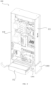
- an air conditioning apparatus 200 comprises a housing 210 and an electric control box 100.
- the electric control box 100 comprises a box body assembly 110, a circuit board assembly 120, and a heat exchanger assembly 130.
- the box body assembly 110 comprises a box body 111 and a connection base 131.
- the box body 111 has a first accommodation cavity 101.
- the circuit board assembly 120 is disposed in the first accommodation cavity 101.
- the heat exchanger assembly 130 comprises a heat exchanger 132.
- the box body 111 and the connection base 131 are connected to each other in a split manner, and the box body 111 has a first opening 1111.
- the connection base 131 has a second accommodation cavity 102.
- the heat exchanger 132 is disposed in the second accommodation cavity 102, that is, the heat exchanger 132 and the circuit board assembly 120 are disposed in two different spaces of the box body 111 and the connection base 131, respectively.
- the box body 111 is movably arranged relative to the connection base 131, that is, the box body 111 and the connection base 131 are independent of each other.
- the box body 111 may be directly moved to a suitable position without disassembling the box body 111 and the heat exchanger 132, which simplifies a technical difficulty of the maintenance operation.
- the heat exchanger 132 does not need to be disassembled, which further ensures convenience of the maintenance operation while avoiding an impact and damage of repeated disassembling on a connection pipeline of the heat exchanger 132.
- a compressor, a gas-liquid separator, a complex refrigerant pipeline, and other components in the housing of the air conditioning apparatus 200 require inspection and maintenance, it is often necessary to disassemble and assemble the electric control box.
- the solution of the present disclosure can easily disassemble a relatively large box body 111 of the electric control box 100. As a result, an operating space is larger and inspection and maintenance of other components of the outdoor unit is more convenient.
- the solution of the present disclosure can also protect the circuit board assembly 120 from condensation drops generated around the heat exchanger 132 as much as possible.
- the box body assembly 110 in the electric control box 100 adopts the split type design, which is split into different components such as the box body 111 and the connection base 131.
- the electronic components in the electric control box 100 are disposed at the box body 111.
- the evaporator is mounted at the connection base 131.
- the evaporator is connected to the refrigerant system flow path through the refrigerant pipeline.
- the box body 111 is detachably connected to the connection base 131.
- the connection base 131 is fixedly mounted in the air conditioning apparatus.
- the box body 111 is movable relative to the connection base 131.
- the heat exchanger 132 cools air through a phase change, a principle of which is that: a refrigerant inside the heat exchanger 132 circulates with an inside of the air conditioning refrigeration system; heat is then absorbed through the phase change of the refrigerant to reduce a temperature of air or airflow inside the electric control box 100; and then heat of the circuit board assembly 120 is dissipated through the relatively low-temperature airflow.
- the electric control box 100 is disposed inside the housing of the outdoor unit.
- Other components of the air conditioning apparatus 200 are further provided in the housing, such as a compressor, a gas-liquid separator, and a complex refrigerant pipeline.
- these components in the housing require inspection and maintenance, it is often necessary to disassemble and assemble the electric control box 100. As a result, an operating space is larger.
- the technical solution in the present disclosure can easily disassemble a relatively large box body 111 of the electric control box 100, and therefore inspection and maintenance of other components of the outdoor unit is more convenient.
- the box body 111 is detachably disposed at the connection base 131; and the connection base 131 has a receiving space 1301.
- the heat exchanger assembly 130 is drawable relative to the connection base 131, to allow the heat exchanger assembly 130 to be disposed in the receiving space 1301, or to be drawn out to an outside of the receiving space 1301.
- the heat exchanger assembly 130 is configured to dissipate heat from the circuit board assembly 120.
- the circuit board assembly 120 and the heat exchanger assembly 130 are separately arranged and are located in different spaces.
- the box body 111 is detachable from the connection base 131.
- the heat exchanger assembly 130 can be drawn out of the receiving space 1301 of the connection base 131.
- it is convenient to perform a separate maintenance operation on the circuit board assembly 120 in the box body 111 or the heat exchanger assembly 130 in the receiving space 1301, and the two of which do not interfere with each other during the maintenance.
- the heat exchanger assembly 130 and the circuit board assembly 120 are in different spaces, it is also possible to prevent condensation drops generated by a refrigerant heat dissipation device from affecting normal operation of the circuit board assembly 120 in the box body 111. Meanwhile, the heat exchanger assembly 130 can serve to dissipate heat from the circuit board assembly 120.
- the heat exchanger assembly 130 is drawable relative to the connection base 131, and when the heat exchanger assembly 130 is in a state of drawing out, the heat exchanger 132 is located outside the receiving space 1301. It should be noted that the heat exchanger assembly 130 is arranged to be drawable, and the heat exchanger assembly 130 may directly draw out during the maintenance of the heat exchanger 132, which is convenient for the maintenance operation.
- the pipeline connecting the heat exchanger 132 to the air conditioning refrigeration system may be arranged as a flexible connection pipeline with a predetermined extending length.
- the connection pipeline has the predetermined length that can meet the heat exchanger 132 to be drawn out of the receiving space 1301, there is no a need to discharge the cooling medium in the heat exchanger 132. In this case, the maintenance operation can be performed without having to disconnect the connection pipeline. In this way, it is convenient and quick.
- the connection pipeline has a suitable length just meeting the heat exchanger assembly 130 to protrude from the receiving space 1301 to control a space occupied by the connection pipeline.
- the heat exchanger assembly 130 comprises a shell 133 and a heat exchanger 132.
- the box body 111 and the shell 133 together define the accommodation cavity, and the heat exchanger 132 is accommodated in the accommodation cavity and configured to dissipate heat from the circuit board assembly 120.
- the shell 133 mentioned herein means a protective shell of the heat exchanger 132 itself.
- the box body 111 and the shell 133 together define the accommodation cavity, which means that an internal space of the box body 111 and an internal space of the shell 133 are in communication with each other, to enable the heat exchanger 132 in the receiving space 1301 of the connection base 131 to dissipate the heat from the circuit board assembly 120 in the box body 111, that is, a heat dissipation channel is formed inside the accommodation cavity.
- the circuit board assembly 120 and the heat exchanger assembly 130 do not interfere with each other during their maintenance, which is convenient and quick.
- an interior of the box body 111 and an interior of the shell 133 of the heat exchanger 132 are in communication with each other to form a heat dissipation air path, which ensures that the heat exchanger assembly 130 has a good heat dissipation effect on the circuit board assembly 120.
- connection base 131 comprises a first support portion 1303 and a second support portion 1304.
- the first support portion 1303 and the second support portion 1304 together enclose the receiving space 1301.
- the second support portion 1304 is configured to carry the heat exchanger 132.
- the second support portion 1304 is arranged in the horizontal direction, and the second support portion 1304 and the first support portion 1303 jointly enclose a lateral opening in communication with the receiving space 1301.
- the lateral opening is configured to allow the heat exchanger assembly 130 to be drawn out of the receiving space 1301. That is, the shell 133 defined by the second support portion 1304 and the first support portion 1303 is not completely closed, but has an opening on its side surface.
- the opening may be essentially regarded as an operating window to facilitate the removal of the heat exchanger 132.
- a guide surface 1324 is provided on a side of the second support portion 1304 facing towards the lateral opening, and the guide surface 1324 is gradually inclined outwardly from an inside of the lateral opening to an outside of the lateral opening.
- the guide surface 1324 can assist in quickly sliding out the heat exchanger 132. Therefore, the heat exchanger 132 is easily removed.
- the guide surface 1324 extends to a bottom surface of the connection base 131. It can be understood that when the heat exchanger assembly 130 slides down along the guide surface 1324, if the guide surface 1324 extends directly to the bottom, the heat exchanger assembly 130 can slide directly along the guide surface 1324 to the bottom. Since the guide surface 1324 can be for supporting in the entire process of removing the heat exchanger 132, the process of removing the heat exchanger 132 is safer and more reliable, avoiding a problem such as slipping or bumping during manual removal, and greatly saving manpower.
- the closed air path is formed in the above-mentioned accommodation cavity, and the heat exchanger 132 cools the air through the phase change of the refrigerant.
- the air path is configured to circulate the air cooled by the heat exchanger 132 and exchange heat with the circuit board assembly 120.
- the box body 111 has a first accommodation cavity 101, and the shell has a second accommodation cavity 102.
- the heat exchanger 132 is located in the second accommodation cavity 102.
- the first accommodation cavity 101 and the second accommodation cavity 102 are in communication with each other to define the accommodation cavity together.
- the air cooled by the heat exchanger 132 can circulate in the first accommodation cavity 101 and the second accommodation cavity 102, to achieve an effect of heat dissipation and cooling for the circuit board assembly 120.
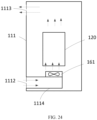
- the first accommodation cavity 101 has a first opening 1111 at a bottom of the first accommodation cavity 101
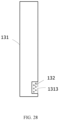
- the second accommodation cavity 102 has a second opening 1311 at a side the second accommodation cavity facing towards the box body.
- the second opening 1311 is correspondingly in communication with the first opening 1111, to enable the first accommodation cavity 101 and the second accommodation cavity 102 to form the above-mentioned air path.
- the housing 133 inevitably has an opening, to enable the first accommodation cavity 101 and the second accommodation cavity 102 to be in communication with each other to form the heat dissipation air path.
- connection base 131 has an avoidance hole 1302.
- the avoidance hole 1302 is disposed between the first opening and the second opening 1311, and the first opening, the avoidance hole 1302 and the second opening 1311 are correspondingly in communication with each other.
- the heat exchanger assembly 130 is disposed in the receiving space 1301 inside the connection base 131, and the second opening 1311 is defined at the shell 133 of the heat exchanger 132. If the second opening 1311 is in communication with the first opening on the box body 111, it is necessary to dispose the avoidance hole 1302 at a position corresponding to the first opening and the second opening 1311 at the connection base 131, to allow the first cavity 1011 and the second cavity 1012 to be in communication with each other to form the air path.
- a partition member 140 is provided in at least one of the first accommodation cavity 101 and the second accommodation cavity 102, and the partition member 140 is configured to partition at least one of the first accommodation cavity 101 or the second accommodation cavity 102 into the aforementioned air path.
- the air path may be divided into two spaces.
- One of the two spaces is used to circulate cold air cooled by the heat exchanger 132.
- the circuit board assembly 120 is disposed in the other one of the two spaces, and the other one of the two spaces is used to circulate hot air formed after the heat dissipation of the circuit board assembly 120.
- Sequentially dividing the hot air and the cold air into two independent paths can avoid mixing the cold air after being cooled by the heat exchanger 132 and the hot air, which causes a temperature of the cold air to rise and reduce the heat dissipation effect on the circuit board assembly 120.
- the partition member 140 comprises a first partition member 141 disposed in the first accommodation cavity 101.
- the first partition member 141 is configured to partition the first accommodation cavity 101 into a first cavity 1011 and a second cavity 1012.
- the first cavity 1011 and the second cavity 1012 are in communication with the first opening.
- the first cavity 1011 and the second cavity 1012 need to form a communicated air path, the first cavity 1011 and the second cavity 1012 inevitably need to be in communication with the first opening.
- the circuit board assembly 120 is disposed in the first cavity 1011, and the second cavity 1012 contains the cold air cooled by the heat exchanger 132.
- the cold air in the second cavity 1012 needs to circulate to flow into the first cavity 1011 in order to achieve the heat dissipation of the circuit board assembly 120.
- first cavity 1011 and the second cavity 1012 are in communication with each other through a first vent opening 1411, to enable the cold air in the first cavity 1011 to flow into the second cavity 1012.
- the first vent opening 1411 is located at an end of the first partition member 141 away from the connection base 131, and the circuit board assembly 120 is disposed in the first cavity 1011.
- the heat exchanger 132 is disposed in the connection base 131, and the cold air in the second cavity 1012 is sourced from an end of the second cavity 1012 close to the heat exchanger 132.
- the cold air should flow from an end of the circuit board assembly 120 to another end of the circuit board assembly 120, that is, from an end away from the connection base 131 into the heat sink 150 in the connection base 131 for cooling, to form the circulation air path. Therefore, the first vent opening 1411 is located at the end away from the connection base 131 in order to achieve the circulation of the air path described above.
- the first partition member 141 may have a through hole to be formed as a vent opening, or a gap left between an end of the first partition member 141 away from the connection base 131 and an inner wall of the box body 111 may be formed as a vent opening, which is not particularly limited herein.
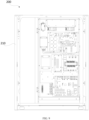
- FIG. 8 is a schematic view of a structure of a heat exchanger assembly of an electric control box according to an embodiment of the present disclosure.
- the shell 133 comprises a bottom plate and a plurality of side plates connected to circumferential outer sides of the bottom plate.
- the bottom plate and the plurality of side plates together enclose the second accommodation cavity 102.
- the second opening 1311 is formed at an edge of the side plate away from the bottom plate. That is, no plate covers the second opening 1311, but the second opening 1311 is in direct communication with the first opening.
- the bottom plate and the plurality of side plates may be integrally formed, or may be detachably spliced with each other to facilitate the maintenance of other components inside the shell 133.
- the shell 133 is detachably fixed to a side wall of the first support portion 1303 to facilitate removal of the heat exchanger assembly 130 from the side wall of the first support portion 1303.
- the side plate has a flange 134 at an edge of the side plate facing away from the bottom plate.
- the flange 134 is attached to the first support portion 1303. It is easy to understand that providing the above-mentioned flange 134 is to facilitate fixing of the shell 133 and also to facilitate disassembling of the shell 133.
- the attachment between the flange and the first support portion 1303 is to ensure satisfactory sealing of the air path, to prevent the air in the air path from leaking out, or prevent air in an ambient environment from flowing into the air path to affect the heat dissipation effect.
- the partition member 140 further comprises a second partition member 142 disposed in the second accommodation cavity 102.
- the second partition member 142 is configured to partition the second accommodation cavity 102 into a third cavity 1021 and a fourth cavity 1022.
- the third cavity 1021 and the fourth cavity 1022 are in communication with the second opening 1311.
- the third cavity 1021 is correspondingly in communication with the first cavity 1011
- the fourth cavity 1022 is correspondingly in communication with the second cavity 1012.
- the third cavity 1021 and the fourth cavity 1022 are in communication with each other through a second vent opening 1412.
- the heat exchanger 132 is disposed in the third cavity 1021 or the fourth cavity 1022.
- the second vent opening 1412 is located at a side of the heat exchanger 132 opposite to the first opening.
- air that absorbs the heat and heats up after flowing through a circuit board flows back to the heat exchanger 132; a refrigerant circulates in the heat exchanger 132 and can cool the air around the refrigerant; the cooled air flows into the second cavity 1012 through the second opening 1311, and then flows into the first cavity 1011 through the first vent opening 1411; and after air in the first cavity 1011 flows through the circuit board assembly 120, it flows back to the heat exchanger 132 again to be cooled. Therefore, the circulation of the air in the entire air path is achieved. Thus, a better heat dissipation and cooling effect on the circuit board assembly 120 is achieved.
- the second partition member 142 has a gap between an end of the second partition member 142 close to the bottom plate and the bottom plate, and the gap serves as the second vent opening 1412. Similar to the arrangement of the first vent opening 1411, this is only one of the simpler arrangements of the vent opening, for there is no need to modify the second partition member 142. In fact, the way of defining the vent opening at the second partition member 142 may also be adopted, as long as the third cavity 1021 and the fourth cavity 1022 are in communication with each other.
- the electric control box 100 further comprises a fan assembly 160.
- the fan assembly 160 comprises at least one fan disposed in the air path. Each of the at least one fan is configured to drive air to circulate and flow along the air path, to allow the air, after being cooled by the heat exchanger 132, to flow to the circuit board assembly 120 to cool the circuit board assembly 120.
- the fan serves to provide power for airflow circulation in the air path, and the number of fans may be considered based on the space, the heat generated by the circuit board assembly 120, a requirement for a heat dissipation speed, etc.
- the heat exchanger 132 may be an evaporator, and the evaporator is connected to a refrigerant flow path 300 of the air conditioning apparatus and is configured to perform cooling through a phase change of a refrigerant flowing through the evaporator.
- the evaporator may have an inlet connected to a low-pressure liquid refrigerant flow path in the refrigerant flow path 300, and an outlet connected to a low-pressure gaseous refrigerant flow path in the refrigerant flow path 300. Therefore, the refrigerant can absorb the heat through its phase change from the liquid to the gas phase, to reduce a temperature of the airflow in the electric control box 100.
- the evaporator is disposed in the electric control box, and the evaporator is connected to the flow path of the refrigerant system through the refrigerant pipeline.
- the box body assembly 110 in the electric control box 100 adopts a split type design, which is split into different components such as the box body 111 and the connection base 131.
- the electronic component in the electric control box 100 is disposed at the box body 111.
- the evaporator is mounted in the connection base 131.
- the evaporator is connected to the refrigerant system flow path through the refrigerant pipeline.
- the box body 111 is detachably connected to the connection base 131.
- the connection base 131 is fixedly mounted in the air conditioning apparatus.
- the box body 111 is movable relative to the connection base 131.
- the electric control box 100 is disposed inside the housing of the outdoor unit.
- Other components of the air conditioning apparatus are also arranged in the housing, such as a compressor, a gas-liquid separator, and a complex refrigerant pipeline.
- these components in the housing require inspection and maintenance, it is often necessary to disassemble and assemble the electric control box 100.
- an operating space is larger.
- This solution in the present disclosure can easily disassemble a relatively large box body 111 of the electric control box 100, and therefore inspection and maintenance of other components of the outdoor unit is more convenient.
- the detachable connection between the box body 111 and the connection base 131 mainly means that there is a variable relative position between the box body 111 and the connection base 131, to allow the box body 111 and the connection base 131 to be in a detachable state.
- the detachable connection between the box body 111 and the connection base 131 comprises but is not limited to:
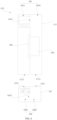
- the refrigerant flow path 300 in the air conditioning apparatus may be a circulation loop formed by sequentially connecting the compressor, the condenser, an expansion valve, and the evaporator in the air conditioning apparatus.
- the above-mentioned components are in communication with each other through a pipeline for circulating the refrigerant.
- a heat exchange is performed in the air conditioning apparatus through the phase change of the refrigerant in the refrigerant flow path 300 during the circulation of the refrigerant to achieve the function of cooling or heating.
- the heat exchanger 132 in the electric control box 100 may be connected to a main flow path of the refrigerant flow path 300 or to a branch flow path of the refrigerant flow path 300, which is not specifically limited in the embodiments of the present disclosure.
- the specific structure of the circuit board assembly 120 comprises the circuit board and the electronic components disposed at the circuit board.
- An amount of heat is generated by the electronic components during operation, which affects the normal operation of the electronic components. Therefore, the above-mentioned heat dissipation structure is essentially to cool down the electronic components.
- the fan is disposed in the first accommodation cavity 101, and the fan comprises an air inflowing side 1611 facing the first vent opening 1411 and an air outflowing side 1612 facing the circuit board assembly 120. It can be understood that the cold air in the first cavity 1011 flows into the second cavity 1012 through the first vent opening 1411, and the power of the cold air flow is provided by the fan, that is, the cold air is drawn in from the air inlet, flows out from the air outlet, and flows through the circuit board assembly 120 to take away heat generated by the electronic components.
- the air inflowing side 1611 facing towards the first vent opening 1411 mentioned herein refers to the air inflowing side 1611 faces towards the first vent opening 1411, but does not necessarily face the first vent opening 1411 directly, and the air outflowing side 1612 does not necessarily face the circuit board assembly 120 directly.
- the electric control box 100 further comprises a heat sink 150 disposed in the accommodation cavity.
- the heat sink 150 is fixedly attached to a back surface of the circuit board assembly 120.
- the heat sink 150 is configured to dissipate heat from the circuit board assembly 120 through heat conduction.
- the two cooling ways complement each other. In this way, an influence of the condensation drops generated in the first accommodation cavity 101 on the circuit board is avoided while achieving the good cooling effect.
- the box body 111 may be located above the connection base 131, and the second accommodation cavity 102 has a second opening 1311, the second opening 1311 is defined at a side of the second accommodation cavity 102 facing towards a bottom surface of the box body 111.
- the second opening 1311 corresponds to the first opening 1111 to enable the first accommodation cavity 101 and the second accommodation cavity 102 to be in communication with each other to form a closed air path.
- the air path is constructed to allow air cooled by the heat exchanger 132 to exchange heat with the circuit board assembly 120, that is, the heat dissipation of the circuit board assembly 120 is achieved by circulating air inside the closed air path. Hot air is cooled by the heat exchanger 132 and flows through the circuit board assembly 120 to achieve the good heat dissipation effect.
- the box body 111 may be rotatably connected to the connection base 131.
- the box body 111 rotates to the first position relative to the connection base 131, the box body 111 has a side wall flush with a side wall of the connection base 131, to enable the electric control box 100 to have a flat outer wall.
- the box body 111 When the box body 111 rotates to the second position relative to the connection base 131, the box body 111 is offset from the connection base 131. In this case, some maintenance operations may be performed on the box body 111 or the heat sink without disassembling the heat exchanger 132.
- the box body 111 of the electric control box 100 is rotatable about a vertical rotary shaft, and the box body 111 is disposed above the connection base 131 when the box body 111 is located at the first position.
- This implementation exemplarily provides a relative position relation between the box body 111 and the connection base 131 of the electric control box 100.
- the connection base 131 is disposed at a bottom side of the box body 111.
- the rotary shaft of the box body 111 is a vertical rotary shaft, that is, the rotary shaft of the box body 111 is positioned at a side of the box body 111, and not positioned in a same direction as the heat exchanger 132.
- the box body 111 rotates relative to the connection base 131, the box body 111 and the connection base 131 do not interference with each other.
- the box body 111 has a bottom wall parallel to a top wall of the connection base 131.
- the bottom wall of the box body 111 is attached to the top wall of the connection base 131.
- the first accommodation cavity 101 inside the box body 111 and the second accommodation cavity 102 inside the connection base 131 need to be in communication with each other, and the way of the communication is to define the corresponding opening at each of the wall of the first accommodation cavity 101 and the wall of the second accommodation cavity 102, that is, the first opening 1111 and the second opening 1311 are defined at the bottom wall of the box body 111 and the top wall of the connection base 131, respectively.
- the bottom wall of the box body 111 and the top wall of the connection base 131 should be flat and attached with each other, with no gap as much as possible, to ensure that the cooling air in the air path is not easy to overflow, and external hot air is not easy to flow into the air path, and thus to ensure the normal air circulation inside the air path. In this way, a good cooling effect is achieved.
- the parallel arrangement of the bottom wall of the box body 111 and the top wall of the connection base 131 is also to achieve the satisfactory attachment, to avoid the gap between the bottom wall of the box body 111 and the top wall of the connection base 131, which results in the overflowing of the internal cold air or the inflowing of the external hot air, and thus affecting heat dissipation effect of electrical element inside the box body 111.
- the first opening 1111 has an edge shape matching an edge shape of the second opening 1311. It can be understood that, in order to form the closed air path, after the bottom wall of the box body 111 is attached to the top wall of the connection base 131, an edge of the first opening 1111 should completely match an edge of the second opening 1311 corresponding to the first opening 1111, to avoid the gap, which results in loose sealing of the air path and affecting the heat dissipation effect of the internal electrical element.
- a projection of the box body 111 in a vertical direction nonoverlaps with a projection of the connection base 131 in the vertical direction.
- Such an arrangement has an advantage that when the box body 111 rotates relative to the connection base 131, for example, when the box body 111 rotates to a maximum angle, the box body 111 and the connection base 131 completely belong to two different planes.
- the box body 111 and the connection base 131 may touch each other during operation, resulting in inconvenience in operation. If the box body 111 rotates to a predetermined position in which the box body 111 may be completely offset from the connection base 131, such problems cannot occur.
- the electric control box 100 further comprises a partition member 140.
- the partition member 140 is disposed in at least one of the first accommodation cavity 101 and the second accommodation cavity 102, and the partition member 140 is configured to partition the first accommodation cavity 101 and the second accommodation cavity 102 into the aforementioned air path.
- the air path may be divided into two spaces.
- One of the two spaces is used to circulate cold air cooled by the heat exchanger 132.
- the circuit board assembly 120 is disposed in the other of the two spaces. Sequentially dividing the hot air and the cold air into two independent paths can avoid mixing the cold air after being cooled by the heat exchanger 132 and the hot air, which cannot maintain the temperature of the cold air, and thus reduces the heat dissipation effect on the circuit board assembly 120.
- the partition member 140 comprises a first partition member 141 disposed in the first accommodation cavity 101.
- the first partition member 141 is configured to partition the first accommodation cavity 101 into a first cavity 1011 and a second cavity 1012, and the first cavity 1011 and the second cavity 1012 are in communication with each other through a first vent opening 1411.
- the first cavity 1011 and the second cavity 1012 are in communication with the first opening 1111.
- the circuit board assembly 120 is disposed in the first cavity 1011.
- disposing the first vent opening 1411 is to allow the first cavity 1011 and the second cavity 1012 to be in communication with each other, to form the air path for the air circulation.
- the cold air circulating in the second cavity 1012 may flow into the first cavity 1011 through the first vent opening 1411, and the cold air flows through the circuit board assembly 120 to achieve the heat dissipation and the cooling of the circuit board assembly 120. That is, the cooling of the circuit board assembly 120 of the present disclosure is achieved by circulating the low-temperature air.
- the circulation of the air at least part of condensation drops generated after the cooling in the first cavity 1011 can be taken away.
- the first cavity 1011 can maintain a dry environment as much as possible. In this way, a risk of damage of the condensation drops to the circuit board assembly 120 is reduced while ensuring the satisfactory cooling of the circuit board assembly 120.
- the circuit board assembly 120 in the box body 111 comprises a circuit board and electronic components.
- the circuit board is fixed at the first partition member 141.
- the electronic components are arranged at a side of the circuit board facing away from the first partition member 141.
- This implementation exemplarily illustrates one of the fixing ways of the electronic components, i.e., fixing against the first partition member 141.
- This fixing way has an advantage that other heat dissipation structures may be arranged at a side of the first partition member 141 opposite to the circuit board, which may also have the heat dissipation and cooling effect on the circuit board assembly 120. If this is not considered, in fact, the circuit board may also be fixed at, for example, an inner wall surface of the first accommodation cavity 101.
- a temperature sensor may be provided at the circuit board assembly 120 and configured to detect a temperature of the electronic components.
- a flow rate of the refrigerant flowing into the heat exchanger 132 can be controlled, to avoid a relatively low temperature of the airflow in the air path, which affects operation of the electronic components.
- a heat sink 150 may also be provided in the first accommodation cavity 101.
- the heat sink 150 corresponds to the circuit board assembly 120.
- the heat sink 150 is configured to dissipate heat from the electronic components through heat conduction.
- the heat sink 150 is fixedly attached to a side of the first partition member 141 facing away from the circuit board assembly 120.
- the partition member 140 further comprises a second partition member 142 disposed in the second accommodation cavity 102.
- the second partition member 142 is configured to partition the second accommodation cavity 102 into a third cavity 1021 and a fourth cavity 1022.
- the third cavity 1021 is correspondingly in communication with the first cavity 1011.
- the fourth cavity 1022 is correspondingly in communication with the second cavity 1012.
- the heat exchanger 132 is disposed in the third cavity 1021 or the fourth cavity 1022.
- a second vent opening 1412 is defined between the third cavity 1021 and the fourth cavity 1022, and the second vent opening 1412 is located at a side of the heat exchanger 132 opposite to the first opening 1111.
- the airflow that absorbs the heat and heats up after passing through the circuit board assembly 120 flows to the heat exchanger 132; a refrigerant flows in the heat exchanger 132 and can cool the airflow passing around the refrigerant; the cooled airflow flows into the second cavity 1012 through the second opening 1311, and then flows into the first cavity 1011 through the first vent opening 1411 to cool the circuit board assembly 120; at this time, the airflow absorbs the heat and heats up, and flows to the heat exchanger 132 again. As such, the circulation of the airflow in the entire air path is achieved, and the better cooling effect is achieved.
- the second partition member 142 is disposed in the second accommodation cavity 102 to allow the second accommodation cavity 102 to be partitioned into the third cavity 1021 and the fourth cavity 1022.
- the third cavity 1021 and the fourth cavity 1022 also serve to partition the inflowing hot airflow and the outflowing cold airflow in space, to avoid mixing of the inflowing hot airflow and the cooled cold airflow that affects the cooling effect.
- the first cavity 1011 is correspondingly in communication with the third cavity 1021
- the second cavity 1012 is correspondingly in communication with the fourth cavity 1022.
- the air path inside the entire electric control box 100 forms a circular flow air path, to realize smooth circulation of the hot airflow and the cold airflow in the air path, to cool the circuit board assembly 120.
- Dividing the internal air path into the two parts enables easier control of a flowing direction of the overall airflow in the air path, and the circulation of the hot airflow and the cold airflow based on their respective specified paths, which prevent a poor cooling effect caused by the mixed flowing of the hot airflow and the cold airflow.
- airflow flowing through the circuit board assembly 120 turns into a cold airflow after flowing through the heat exchanger 132.
- the cold airflow flows into the fourth cavity 1022 through the second vent opening 1412, and then flows into the second cavity 1012 from the fourth cavity 1022.
- a same path is also used when the heat exchanger 132 is disposed in the fourth cavity 1022.
- the second vent opening 1412 is located at a side of the heat exchanger 132 opposite to the second opening 1311, in order to ensure that only the airflow cooled by the heat exchanger 132 can flow into the second cavity 1012 through the third cavity 1021 and the fourth cavity 1022, to ensure that the airflow flowing into the second cavity 1012 is an airflow with a lowest temperature.
- the heat exchanger 132 may have a drain opening, to allow condensation drops to be discharged from the drain opening to keep environment dry.
- the electric control box may further comprise a fan assembly 160.
- the fan assembly 160 comprises at least one fan 161 disposed in the air path.
- Each of the at least one fan 161 is configured to drive air to circulate and flow along the air path, to allow the air, after being cooled by the heat exchanger 132, to flow to the circuit board assembly 120 and cool the circuit board assembly 120.
- the fan 161 actually serves to provide power for the circulation of the airflow in the air path.
- the number of fans may be considered based on the space, a requirement for a heat dissipation speed, etc.
- the first partition member 141 and/or the second partition member 142 are/is in a plate shape. It should be noted that the first partition member 141 and the second partition member 142 mainly serve to separate the first accommodation cavity 101 and the second accommodation cavity 102 into two cavities, respectively. Therefore, a partition plate of any structure may be used as long as it can provide partitioning. However, given that the circuit board assembly 120 needs to be fixed at the first partition member 141, it is more convenient to select a partition member 140 that has a relatively flat plate-shaped structure, and the plate-shaped partition member 140 also enables a smoother circulation of the airflow in the air path.
- the air conditioning apparatus 200 adopts the technical solutions in the above-mentioned embodiments, the air conditioning apparatus 200 at least has the beneficial effects brought by the technical solutions in the above-mentioned embodiments, which will not be repeated herein.
- the housing 210 comprises upright posts 211.
- the box body 111 is rotatably connected to one of the upright posts 211.
- the box body 111 protrudes from the housing 210, that is, the box body 111 is rotatably connected to the upright post 211.
- the box body 111 is rotatable relative to the connection base 131.
- the maintenance operation of the circuit board assembly 120 in the box body 111 is more convenient.
- the air conditioning apparatus may further comprise a limit assembly.
- the limit assembly and at least one of the box body and the connection base are relatively fixed, and the limit assembly is configured to fix the box body at the first position.
- the limit assembly comprises a limit member.
- the limit member is disposed on the connection base or the connection base, and the limit member is located in a rotation trajectory of the box body to stop the box body at the first position.
- the housing 210 further comprises a hinge assembly configured to connect the box body 111 and the upright post 211.
- the hinge assembly comprises a plurality of hinge members 212.
- Each of the plurality of hinge members 212 comprises a first fixing portion fixed to the box body 111 and a second fixing portion fixed to the upright post 211.
- the first fixing portion is rotatably connected to the second fixing portion.
- the flexible rotation of the box body 111 can be facilitated by connecting the box body 111 to the upright post 211 using the hinge members 212.
- the air conditioning apparatus further comprises a seal member (not shown).
- the seal member is configured for sealing between the first opening 1111 and the second opening 1311 when the box body 111 is located at the first position.
- connection base 131 is connected sequentially to the box body 111 from top to bottom, and the box body 111 is movable relative to the connection base 131, to allow the box body 111 and the connection base 131 together to form a detachable electric control box 100 when the box body 111 moving to a position below the connection base 131.
- the box body 111 and the connection base 131 together enclose an accommodation cavity.
- a projection of the connection base 131 in a vertical direction and a projection of the box body 111 in the vertical direction at least partially overlap.
- the heat exchanger 132 and the circuit board assembly 120 are located in the accommodation cavity.
- the box body 111 is movable relative to the connection base 131, to enable the box body assembly 110 to be in a detached state or an undetached state.
- the box body 111 and the connection base 131 may together enclose the accommodation cavity.
- the electric control box 100 may operate to control operation of the air conditioning apparatus.
- a space behind the box body 111 may be exposed, to facilitate inspection and maintenance of the air conditioning apparatus by an operator.
- the box body 111 may be rotatable relative to the connection base 131, to allow the box body 111 to rotate to the position below the connection base 131, and to allow the box body 111 and the connection base 131 together to enclose the accommodation cavity; or the box body 111 and the connection base 131 are offset from each other horizontally to enable the box body assembly 110 to be in the detached state.
- the air conditioning apparatus further comprises an upright post 211.
- the upright post 211 and the outdoor unit 230 are relatively fixed, and the box body 111 is rotatably connected to the upright post 211.
- the air conditioning apparatus may further comprise a fan 161 and a partition member 140.
- the partition member 140 may be disposed in the accommodation cavity and configured to partition the accommodation cavity into a circulation air path.
- the circuit board assembly 120 and the heat exchanger 132 are sequentially arranged in an extending direction of the circulation air path.
- the heat exchanger 132 is located at the connection base 131 and at a top of the accommodation cavity.
- the heat exchanger 132 is configured to cool air flowing through the heat exchanger 132 through a phase change of a cooling medium.
- the fan 161 is configured to drive the air to flow along the circulation air path.
- a cooling airflow may be formed in the accommodation cavity when the fan 161 is started.
- the cooling airflow may sequentially flow through the heat exchanger 132 and the circuit board assembly 120 in the accommodation cavity.
- the cooling airflow flows through the heat exchanger 132 when the cooling airflow flows into the connection base 131 and through the top of the accommodation cavity.
- the heat exchanger 132 when in operation, can cool the cooling airflow, absorb heat of the cooling airflow flowing through the heat exchanger 132, and reduce a temperature of the cooling airflow. Therefore, the temperature of the cooling airflow can be lower than a surface temperature of the circuit board assembly 120 during the operation of the circuit board assembly 120.
- the cooling airflow when flowing through the circuit board assembly 120, can exchange the heat with the circuit board assembly 120, take away the heat of the circuit board assembly 120, and reduce the temperature of the circuit board assembly 120. In this way, the effect of heat dissipation is achieved.
- the box body 111 of the electric control box 100 can be movable relative to the connection base 131 with the box body assembly 110 of the electric control box 100 in the split type design. That is, when the electric control box 100 is assembled into the air conditioning apparatus, the connection base 131 may be relatively fixed; the box body 111 may be movable relative to the connection base 131; and the heat exchanger 132 introduced with the cooling medium is disposed at the connection base 131.
- the air conditioning apparatus requires the maintenance, only the box body 111 needs to be moved, without having to move the connection base 131, eliminating the need to cut off the refrigerant pipeline and recover the cooling medium. In this way, the electric control box 100 is easily disassembled and convenience of the maintenance is improved.
- the electric control box 100 when the electric control box 100 is applied to an air conditioning apparatus, the electric control box 100 may be mounted in the housing 210 of the air conditioning apparatus.
- a component such as a compressor, a fan, and a cooling medium pipeline may also be mounted in the housing 210.
- the connection base 131 may be fixedly connected to the housing 210 of the air conditioning apparatus, and the box body 111 may be rotatable relative to the housing 210 of the air conditioning apparatus. Therefore, the relative movement between the box body 111 and the connection base 131 can be achieved.
- the heat exchanger 132 may be an evaporator.
- the heat exchanger 132 may be connected to the refrigerant flow path 300 of the air conditioning apparatus, and the heat exchanger 132 is configured to perform cooling through a phase change of a refrigerant, that is, the cooling medium pipeline of the outdoor unit 230 may serve, in the electric control box 100, as the heat exchanger 132, to achieve an effect of heat exchange.
- the heat of the cooling airflow in the accommodation cavity can be absorbed using the phase change of the cooling medium to achieve the cooling effect.
- the evaporator may have an inlet connected to a low-pressure liquid refrigerant flow path in the refrigerant flow path 300, and an outlet connected to a low-pressure gaseous refrigerant flow path in the refrigerant flow path 300.
- the low temperature of the heat exchanger 132 only affects the air and the airflow in the accommodation cavity. The airflow after being cooled for the heat dissipation can avoid the condensation drops generated due to overcooling of the circuit board assembly 120, and ensure that the circuit board assembly 120 can operate satisfactorily.
- the refrigerant flow path 300 in the air conditioning apparatus may be a circulation loop formed by sequentially connecting the compressor, the condenser, an expansion valve, and the evaporator in the air conditioning apparatus.
- the above-mentioned components are in communication with each other through the pipeline for circulating the refrigerant.
- the heat exchange is performed in the air conditioning apparatus through the phase change of the refrigerant in the refrigerant flow path 300 during the circulation of the refrigerant to achieve the function of cooling or heating.
- the heat exchanger 132 in the electric control box 100 may be connected to a main flow path of the refrigerant flow path 300 or to a branch flow path of the refrigerant flow path 300, which is not specifically limited in the embodiments of the present disclosure.
- the evaporator is disposed in the electric control box, and the evaporator is connected to the flow path of the refrigerant system by the refrigerant pipeline.
- the component in the electric control box 100 requires inspection and maintenance, it is necessary to destructively cut off the refrigerant pipeline connected to the evaporator and recover a cooling medium in the refrigerant pipeline if the electric control box 100 is disassembled as a whole to the outside of the housing. After the inspection and maintenance is completed, it is necessary to re-weld the cut refrigerant pipeline when the electric control box 100 is mounted in the housing. Such an inspection and maintenance process is very cumbersome.
- Other components are arranged in the housing of the air-conditioning outdoor unit, such as a compressor, a gas-liquid separator, a complex refrigerant pipeline. When these components fail, it is often necessary to move the electric control box 100 to enable a larger operation space.
- the box body assembly 110 in the electric control box 100 adopts the split type design, which is divided into different components such as the box body 111 and the connection base 131.
- the electronic components in the electric control box 100 are disposed at the box body 111.
- the evaporator is mounted in the connection base 131.
- the evaporator is connected to the refrigerant system flow path through the refrigerant pipeline.
- the box body 111 is detachably connected to the connection base 131.
- the connection base 131 is fixedly mounted in the air conditioning apparatus, and the box body 111 is movable relative to the connection base.
- the box body 111 is detachable from the connection base 131, and the inspection and maintenance of the electronic components disposed in the box body 111 can be conveniently achieved without disassembling the evaporator, thereby avoiding the cumbersome process of cutting and re-welding the refrigerant pipeline caused by disassembling the evaporator.
- the disassembling process and the assembling process are relatively simple and easy.
- a relatively large box body assembly 110 of the electric control box 100 can be easily disassembled, and therefore the inspection and maintenance of other components of the outdoor unit is more convenient.
- the circuit board assembly 120 is configured to control operation of the air conditioning apparatus, for example, to control operation of a compressor, a fan, and other components in the air conditioning apparatus.
- the circuit board assembly 120 may be configured to control operation of the fan 161 in the electric control box 100.
- the accommodation cavity may be a closed accommodation cavity
- the electric control box 100 is correspondingly a closed electric control box 100
- This configuration also provides rainproof and corrosion prevention when applied in an outdoor environment. Meanwhile, external water vapor is not easy to enter the electric control box 100, and a limited water vapor content exists in the accommodation cavity of the electric control box 100.
- the heat exchanger 132 when absorbing heat of the cooling airflow for cooling, also has a dehumidification effect on the air. Therefore, the condensation drops are not easy to occur in the electric control box 100.
- the box body 111 is rotatable about a vertical rotary shaft relative to the connection base 131. That is, the box body 111, as a detachably movable component, has a rotation axis extending vertically. Therefore, stability of a movement direction of the box body 111 relative to the connection base 131 is ensured to avoid interference when the box body 111 rotates relative to the connection base 131.
- the box body 111 may be drawn to rotate towards an outside of the air conditioning apparatus, and the box body 111 may pivot to the outside of the housing 210 of the air conditioning apparatus.
- the connection base 131 does not need to be disassembled.
- the operator can check and repair the component behind the box body 111, such as the compressor.
- the box body 111 When the box body 111 and the connection base 131 together enclose an accommodation cavity, the box body 111 may be located directly below the connection base 131. Thus, the box body 111 and the connection base 131 can maintain an up-down arrangement pattern to ensure integrity of the accommodation cavity for circulating the cooling airflow.
- a projection of the box body 111 and a projection of the connection base 131 may not overlap each other, exposing a space below the connection base 131. Thus, the inspection and maintenance of the components in the air conditioning apparatus is facilitated.
- the box body 111 has a first accommodation cavity 101, and the first accommodation cavity 101 may have a first opening 1111 at a top of the first accommodation cavity 101; the connection base 131 has a second accommodation cavity 102, and the second accommodation cavity 102 may have a second opening 1311 at a bottom of the second accommodation cavity 102.
- the first opening 1111 and the second opening 1311 face towards each other.
- the box body 111 moves relative to the connection base 131 and the box body assembly 110 is in a detached state, the first opening 1111 and the second opening 1311 are offset from each other.
- the first accommodation cavity 101 and the second accommodation cavity 102 may together define the accommodation cavity.
- a closed space may be formed in the electric control box 100 for the flowing of the cooling airflow, avoiding an impact of the external environment.
- a top edge of a wall of the first accommodation cavity 101 encloses a first opening 1111.
- the first opening 1111 may be in a square shape, and the box body 111 may also be in a square shape. Since a predetermined space is required inside the box body 111 for the mounting of the component such as the circuit board assembly 120, a size of the first opening 1111 may be controlled by an easily inward flange at the top of the box body 111. That is, the first opening 1111 is formed by the top flange of the first accommodation cavity 101.
- the first opening 1111 may also be in a circular shape or in a shape of other regular polygons, which is not specifically limited in the embodiments of the present disclosure.
- a bottom edge of the second accommodation cavity 102 may enclose a second opening 1311.
- the second opening 1311 may have a shape matching a shape of the first opening 1111, which will not be repeated herein, to facilitate the assembling of the components inside the connection base 131.
- a seal member (not shown) is provided between the first opening 1111 and the second opening 1311, and the seal member is configured for sealing at a periphery of the first opening 1111 and the second opening 1311.
- the seal member may be a seal strip, a seal spacer, etc., and may be made of rubber, silicone, etc., which are not specifically limited in the present disclosure.
- the partition member 140 may comprise a first partition member 141 and a second partition member 142 that are vertically arranged sequentially from top to bottom.
- the first partition member 141 is connected to the box body 111
- the second partition member 142 is connected to the connection base 131.
- the partition member 140 can form a circulation air path in the accommodation cavity while avoiding interference of the partition member 140 when the box body 111 is opened.
- the first partition member 141 may be connected to the box body 111 by a fastener, such as a screw, a bolt, a bayonet, etc.
- the second partition member 142 may be connected to the box body 111 through welding.
- the second partition member 142 may be inserted into and engaged with the accommodation cavity, and a guide groove is disposed at an inner wall of the first accommodation cavity 101 for limiting.
- the specific connection way between the first partition member 141 and the box body 111 is not limited in the embodiment of the present disclosure.
- the second partition member 142 may be arranged in the connection base 131 in a manner similar to the first partition member 141, which is not repeated herein.
- the first partition member 141 and an inner wall of the first accommodation cavity 101 may define a first air path
- the second partition member 142 and an inner wall of the second accommodation cavity 102 may define a second air path.
- the first air path and the second air path are in communication with each other end to end to form a circulation air path.
- the cooling airflow sequentially flows through the first accommodation cavity 101 and the second accommodation cavity 102 to form a cycle. In this way, smoothness of the cooling airflow is ensured.
- the first air path in the box body 111 may have an "U"-shaped shape facing upward, and the second air path in the connection base 131 may have an "U"-shaped shape facing downward.
- the "U"-shaped first air path and the "U"-shaped second air path are in communication with each other to form a ring-shaped circulation air path.
- each of the first partition member 141 and the second partition member 142 may be a partition plate.
- the first partition member 141 has an extending direction same as an extending direction of the second partition member 142.
- the first partition member 141 has plate surfaces flushing with plate surfaces of the second partition member 142. As a result, the first partition member 141 and the second partition member 142 collectively can provide satisfactory guidance for the cooling airflow.
- the electric control box 100 may further comprise a hinge assembly disposed at a side of the box body 111.
- the hinge assembly may comprise a plurality of hinge members.
- Each of the plurality of hinge members may comprise a first fixing portion and a second fixing portion that are rotatably connected to each other.
- the first fixing portion is connected to the box body 111
- the second fixing portion is connected to the upright post 211 outside the electric control box 100.
- the box body 111 may pivot towards the side of the box body 111 relative to the connection base 131 and opened to facilitate the mounting and the connection of the box body 111.
- the upright post 211 is disposed in the air conditioning apparatus and may extend vertically at the air conditioning apparatus.
- the hinge assembly may be of a hinge structure, and the first fixing portion may be connected to an outer wall of the box body 111 by a threaded fastener, and the second fixing portion may be connected to the upright post 211 by a threaded fastener.
- a plurality of hinge assemblies are provided.
- the plurality of hinge assemblies may be arranged at intervals in a height direction of the box body 111. In this way, reliability and stability of the mounting of the box body 111 can be improved.
- the plurality of hinge assemblies may be two, three or more, which is not limited in the embodiments of the present disclosure.
- the electric control box 100 may further comprise a water receiving tray (not shown).
- the water receiving tray may be located below the heat exchanger 132 and configured to wrap a bottom end of the heat exchanger 132.
- the connection base 131 may have a drain opening in communication with the water receiving tray.
- the water receiving tray can receive condensed water on the heat exchanger 132 to prevent the condensed water from dripping and affecting the other components inside the electric control box 100.
- the water receiving tray may have a shape matching a projection shape of the heat exchanger 132 in the vertical direction.
- the water receiving tray may be disposed in the connection base 131 or in the box body 111.
- the water receiving tray may be disposed at the bottom of the box body 111 when disposed in the box body 111, which avoids the flow path of the cooling airflow and ensures the smoothness of the cooling airflow.
- the partition member 140 and two opposite sides of the accommodation cavity form a first cavity 1011 and a second cavity 1012, respectively, and each of an upper end and a lower end of the partition member 140 and the wall of the accommodation cavity define a first vent opening 1411 and a second vent opening 1412, respectively.
- a top end of the first cavity 1011 and a top end of the second cavity 1012 are in communication with each other through the first vent opening 1411, and a bottom end of the first cavity 1011 and a bottom end of the second cavity 1012 are in communication with each other through the second vent opening 1412.
- the first cavity 1011, the first vent opening 1411, the second cavity 1012, and the second vent opening 1412 may together form a circulation air path, and therefore circular flowing of the cooling airflow can be efficiently achieved in the accommodation cavity. As a result, a temperature of the cooling airflow can be maintained within a reasonable range. In this way, a good heat dissipation effect is guaranteed.
- a heat sink 150 may be provided in the electric control box 100.
- the heat sink 150 may also be located in the accommodation cavity.
- the heat sink 150 may be understood as an extension of a heat dissipation surface or a heat dissipation structure of the circuit board assembly 120.
- the heat of the circuit board assembly 120 may be transferred to the heat sink 150.
- the circuit board assembly 120 may comprise a circuit board 121 and a plurality of electrical elements 122.
- the plurality of electrical elements 122 are arranged at the circuit board 121 and electrically connected to each other to form a circuit structure.
- the heat is mainly generated by the electrical elements 122 and transferred to the circuit board 121.
- the cooling airflow flows through the circuit board assembly 120, it can take away part of the heat by blowing the electrical elements 122 and the circuit board 121.
- the electrical elements 122 may comprise but are not limited to controllers, capacitors, filters, reactors, wiring sockets, etc., and the circuit structure of the electrical elements 122 connected to each other is not limited in the present disclosure.
- the electrical elements 122 may be connected to an external power supply or an electrical device by a cable, and the electrical control box 100 may have a wire passing hole.
- a seal rubber ring may be provided at the wire hole for sealing to prevent the cooling airflow from overflowing.
- the circuit board assembly 120 may be disposed in the first cavity 1011, and the heat sink 150 may be disposed in the second cavity 1012.
- the circuit board assembly 120 and the heat sink 150 are connected to two sides of the first partition member 141, respectively, and the heat sink 150 is thermally connected to the electrical elements. Therefore, the heat of the circuit board assembly 120 can be conducted by using the heat sink 150. In this way, an effective air cooling and heat dissipation area of the circuit board assembly 120 is increased and the heat dissipation efficiency is improved.
- the heat sink 150 may be relatively independent from the circuit board assembly 120. During the assembling, the heat sink 150 may be mounted at a side of the circuit board 121 facing away from the electrical element 122. Alternatively, the heat sink 150 may also serve as a derivative structure of the circuit board 121, and the heat sink 150 and the circuit board 121 may be fixedly connected to each other or integrally formed.
- the circuit board 121 may be a mounting plate for the electrical element 122, which is not specifically limited in the embodiments of the present disclosure.
- the heat sink 150 may have a plurality of heat dissipation fins arranged at intervals. There are gaps between the plurality of heat dissipation fins for the circulation of the airflow. Heat of the heat dissipation fins can be taken away when the cooling airflow flows through the gaps between the plurality of heat dissipation fins. In this way, a contact area between the cooling airflow and the plurality of heat dissipation fins can be increased.
- the heat sink 150 may have a heat dissipation channel.
- the heat dissipation channel may extend in a flowing direction of the cooling airflow.
- the cooling airflow may flow through the heat sink 150 through the heat dissipation channel.
- the heat of the heat sink 150 may be taken away when the cooling airflow is in contact with an inner wall of the heat dissipation channel, which can not only ensure the heat dissipation effect, but also can serve to guide the flowing of the cooling airflow.
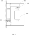
- the fan 161 may be disposed inside the box body 111 and located at a side of the first partition member 141 facing towards the first cavity 1011, and cooling airflow formed by the fan 161 may flow clockwise or counterclockwise in the accommodation cavity.
- cooling airflow flows clockwise.
- the cooling air flows out from an outflowing side of the fan 161 and flows upward. After flowing through the first vent opening 1411, the cooling airflow flows into the second cavity 1012 from the first cavity 1011, and then flows downward and through the heat exchanger 132 and the heat sink 150 in sequence, and reaches the bottom of the second cavity 1012.
- the cooling airflow flows into the first cavity 1011 through the second vent opening 1412, and then flows upward from the bottom of the first cavity 1011 and through the circuit board assembly 120, and returns to an air inflowing side of the fan 161.
- a process of the cooling airflow flowing counterclockwise is opposite to the process described above, which will not be repeated herein.
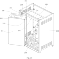
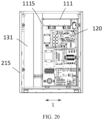
- the electric control box 100 is disposed in the housing 210.
- the housing 210 is provided with an upright post 211.
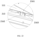
- the housing 210 is provided with a transverse beam 213 at a top of the housing 210.
- the box body 111 of the electric control box 100 is rotatably connected to the upright post 211.
- the connection base 131 of the electric control box 100 is mounted at the transverse beam 213.
- the upright post 211 may be located at a front side of the housing 210, and extends from the top of the housing 210 to a bottom of the housing 210.
- Two transverse beams 213 may be provided, and the connection base 131 may be mounted between the two transverse beams 213.
- the air conditioning apparatus further comprises a limit assembly relatively fixed to at least one of the box body 111 and the connection base 131.
- the limit assembly is configured to fix the box body 111 at the first position.
- the first position refers to a position when the box body 111 is closed relative to the connection base 131. In this case, the box body 111 and the connection base 131 together enclose the accommodation cavity.
- the limit assembly may comprise a limit member 180 disposed on the connection base 111 or the connection base 131.
- the limit member 180 is located in a rotation trajectory of the box body 111 to stop the box body 111 at the first position.
- the limit member 180 may be located at a top edge of the box body 111 and protrudes from the box body 111.
- the housing 210 has a limit surface 214 at the top edge of the housing 210.
- the limit member 180 is capable of abutting with the limit surface 214.
- the box assembly 110 comprises a box body 111 and a connection base 131 disposed in a direction of a horizontal side of the box body 111.
- the box body 111 is movably connected to the connection base 131, to allow the box body 111 to move to be horizontally docked with the connection base 131, or to move to be offset from the connection base 131.
- the box body 111 and the connection base 131 together enclose the accommodation cavity.
- the box body assembly 110 is in the undetached state.
- the circuit board assembly 120 is disposed in the box body 111, the heat exchanger 132 is disposed in the connection base 131, and the heat exchanger 132 and the circuit board assembly 120 are both located in the accommodation cavity when the box body 111 is docked with the connection base 131.
- the box body 111 is movably connected to a connection base 131.
- the box body 111 and the connection base 131 are docked with each other and enclose the accommodation cavity.
- the airflow cooled by the heat exchanger 132 in the connection base 131 may flow into the box body 111, thereby performing heat exchange and cooling on the electrical element 122, to ensure the cooling effect on the electrical element 122.
- the box body 111 and the connection base 131 may be in the detached state with the box body 111 moved to be offset from the connection base 131. In this case, the disassembling, inspection, and maintenance of the circuit board assembly 120 are no longer constrained by the heat exchanger 132 mounted in the connection base 131, which facilitates the maintenance and the disassembling of the circuit board assembly 120 and is convenient to use.
- the heat exchanger 132 is not directly attached to the circuit board assembly 120 for the heat exchange, thereby avoiding the generation of the condensation water caused by local overcooling of the circuit board assembly 120, hence avoiding the condensation water from affecting the normal operation of the circuit board assembly 120. In this way, use safety is improved.
- the box body 111 is configured to rotate about a rotary shaft relative to the connection base 131, to allow the box body 111 to pivot to be docked with the connection base 131, and to allow the box body 111 and the connection base 131 together to enclose the accommodation cavity, or to allow the box body 111 to pivot to be offset from the connection base 131. It is convenient for the box body 111 to change its position relative to the connection base 131 through the rotation of the box body 111. Therefore, when the box body 111 pivots to be docked with the connection base 131, the airflow cooled by the heat exchanger 132 in the connection base 131 can dissipate and cool the circuit board assembly 120 in the box body 111. When the box body 111 pivots to be offset from the connection base 131, the circuit board assembly 120 can be disassembled and repaired conveniently without being restrained by the heat exchanger 132 in the connection base 131. In this way, the inspection and maintenance is convenient.
- the air flowing through the heat exchanger 132 turns into the cooling airflow, and exchanging the heat of the circuit board assembly 120 with the cooling airflow can not only achieve the purpose of the heat dissipation and the cooling of the circuit board assembly 120, but also prevent the excessively low local surface temperature of the circuit board assembly 120, avoiding the water vapor condensation due to the overcooling of the circuit board assembly 120, thereby avoiding the generation of the condensation drops to ensure the normal operation of the circuit board assembly 120. In this way, possibility of safety accidents is reduced.
- the air conditioning apparatus comprises an indoor unit 220 and an outdoor unit 230 connected to each other, and an electric control box is located in the outdoor unit 230.
- the indoor unit 220 and the outdoor unit 230 are connected to each other through a refrigerant flow path 300.
- the air conditioning apparatus further comprises a refrigerant flow path 300
- the heat exchanger 132 comprises an evaporator.
- the evaporator has an inlet connected to a low-pressure liquid refrigerant flow path 300 in the refrigerant flow path 300, and an outlet connected to a low-pressure gaseous refrigerant flow path 300 in the refrigerant flow path 300.
- the evaporator is connected to the refrigerant flow path 300, and configured to cool air flowing through a surface of the evaporator through a phase change of a refrigerant flowing through the evaporator.
- the refrigerant in the refrigerant flow path 300 is in a liquid state before being introduced into the inlet of the evaporator. After passing through the evaporator, the refrigerant is transported in a gaseous state. Because the refrigerant in the evaporator changes from the liquid state to the gaseous state or a gas-liquid mixed state, it absorbs a large amount of heat from the air in the accommodation cavity. In this way, the effect of the cooling and the heat dissipation on the air in the accommodation cavity is achieved.
- the circuit board assembly 120 comprises an electrical element 122 disposed in the box body 111.
- the box body 111 serves to protect the electrical element 122, and enables the airflow cooled by the heat exchanger 132 to be in full contact with the electrical element 122 for the cooling and the heat dissipation of the electrical element 122.
- the housing comprises a support frame 215.
- An upright post is disposed in the support frame 215.
- the upright post and the air conditioning apparatus are relatively fixed.
- the electric control box is disposed in the support frame 215.
- the connection base 131 is connected in the support frame.
- an inner cavity of the connection base 131 and an inner cavity of the box body 111 are in communication with each other and together enclose the accommodation cavity; and when the box body 111 pivots to be offset form the connection base 131, the box body 111 at least partially extends out of the support frame 215.
- the heat exchanger 132 in the connection base 131 cools the airflow passing through the heat exchanger 132 through the phase change of the refrigerant.
- the cooled airflow may flow into the box body 111 to perform the heat exchange and the cooling on the electrical element 122. It is only necessary to pivot the box body 111 during the disassembling and the maintenance.
- the box body 111 pivots from the position where the box body is horizontally docked with the connection base 131 to a position where the box body is offset from the connection base 131, and the box body 111 at least partially extends out of the support frame 215. Therefore, the electrical element 122 can be exposed, which is convenient for the maintenance and the disassembling. After the maintenance is completed, the box body 111 pivots from the position where the box body is offset from the connection base to the position where the box body is horizontally docked with the connection base 131. In this way, it is convenient for the mounting, saving time and effort.
- connection base 131 When the box body 111 pivots to be docked with the connection base 131 horizontally, the inner cavity of the connection base 131 and the inner cavity of the box body 111 are in communication with each other and together enclose the accommodation cavity; and when the box body 111 pivots to be offset form the connection base 131, the connection base 131 at least partially extends out of the support frame 215.
- a fan 161 is further comprised.
- the fan 161 is configured to drive air to flow in the accommodating cavity, to allow air flowing through the heat exchanger 132 to flow to the circuit board assembly 120. Under an action of the fan 161, the airflow is driven to circulate in the accommodating cavity, to allow the airflow cooled by the heat exchanger 132 to perform the heat exchange and the cooling on the electrical element 122.
- the heat exchanger 132 absorbs the heat through the phase change of the refrigerant flowing inside the heat exchanger 132, and therefore the air flowing through the surface of the heat exchanger 132 is cooled and forms the cooling airflow.
- the fan 161 provides power for the airflow to circulate in the circulation air path, and therefore the airflow cooled by the heat exchanger 132 in the connection base 131 is transported to the box body 111 to perform the heat exchange and the cooling on the electrical element 122.
- the airflow that takes away the heat of the electrical element 122 is then transported to the connection base 131 to be cooled by the heat exchanger 132, and therefore the circulation of the airflow is realized for the heat exchange and the cooling of the electrical element 122, avoiding a high temperature of the electrical element 122 that affects its performance and service life as well as causes safety hazards such as fire. Meanwhile, since the electrical element 122 is cooled by the cooling airflow with a lower temperature, it is not easy to generate the water vapor condensation when the cooling airflow with the lower temperature encounters the surface of the electrical element 122 with the higher temperature. Thus, the generation of the condensation drops on the electrical element 122 is avoided.
- the housing has a rotary shaft extending in a direction in which the box body 111 and the connection base 131 are arranged.
- the box body 111 pivots, it rotates about the rotary shaft with an axial direction of the rotary shaft as a central rotation axis.
- the extending direction of the rotary shaft determines a pivoting direction of the box body 111.
- the rotary shaft in order to facilitate the pivoting movement of the box body 111, the rotary shaft extends in a direction in which the box body 111 and the connection base 131 are arranged, and the rotary shaft may extend horizontally.
- Such a structure facilitates the pivoting movement of the box body 111.
- the inner cavity of the connection base 131 and the inner cavity of the box body 111 are in communication with each other and together enclose the accommodation cavity.
- a direction indicated by arrow X in FIG. 20 represents the extending direction of the rotary shaft.
- connection base 131 and the box body 111 are arranged in a left-right direction, the rotary shaft extends in the left-right direction in a horizontal plane; and when the connection base 131 and the box body 111 are arranged in a front-back direction, the rotary shaft extends in the front-back direction in a horizontal plane.
- the support frame 215 comprises a transverse beam 213, and the box body 111 is rotatably disposed at the transverse beam 213 to pivot relative to the connection base 131.
- the transverse beam 213 is located at a top end or a bottom end of the connection base 131 and is relatively fixed to the connection base 131, and the connection base 131 and the box body 111 are arranged at different positions of the transverse beam 213 in the length direction of the transverse beam 213, respectively.
- the transverse beam 213 may be an elongated plate with two ends fixed to two side walls of the support frame 215, respectively.
- the transverse beam 213 When the transverse beam 213 is located at the top end of the connection base 131, there is a predetermined distance between the bottom of the box body 111 and a bottom surface of the support frame 215, ensuring that the pivoting movement of the box body 111 is not affected.
- the transverse beam 213 when the transverse beam 213 is located at the bottom end of the connection base 131, there is a predetermined distance between the top of the box body 111 and a top surface of the support frame 215, ensuring that the pivoting movement of the box body 111 is not affected.
- the control apparatus further comprises a hinge device 216, and the box body 111 is hinged to the support frame 215 by the hinge device 216.
- the box body 111 is hinged to the transverse beam 213 by the hinge device 216.
- the hinge device 216 comprises a first hinge 2161, a second hinge 2162, and a hinge shaft 2163.
- the first hinge 2161 is rotatably connected to the second hinge 2162 by the hinge shaft 2163.
- the first hinge 2161 is fixed to the outer wall of the box body 111.
- the support frame 215 has a front side end connected to the transverse beam 213.
- the second hinge 2162 is fixed to the transverse beam 213.
- the first hinge 2161 may be connected to the outer wall of the box body 111 by screws, and the second hinge 2162 may be connected to the transverse beam 213 by screws.
- the hinge device 216 is a hinge
- the rotatory shaft is a hinge shaft 2163.
- the support frame 215 has a first upright post facing towards the connection base 131 and a second upright post facing away from the connection base 131.
- the rotary shaft is fixedly connected between the first upright post and the second upright post, and the box body 111 may be rotatable about the rotary shaft.
- the box body 111 is rotatable between the first upright post and the second upright post to pivot relative to the connection base 131.
- the first upright post may have two ends connected to a top surface and a bottom surface of the support frame 215, respectively, and the second upright post may have two ends connected to the top surface and the bottom surface of the support frame 215, respectively.
- the rotary shaft may have two ends rotatably connected to the first upright post and the second upright post, respectively.
- the box body 111 is located between the first upright post and the second upright post and is fixedly connected to the rotary shaft. Therefore, the pivoting movement of the box body 111 can be realized by rotating the rotary shaft relative to the first upright post and the second upright post.
- the box body 111 has a first limit device 1115.
- the first limit device 1115 is configured to ensure consistency of the position where the box body 111 pivots to horizontally but-joined with the connection base 131 each time.
- the first limit device 1115 comprises flanges arranged at two outer side walls of the box body 111. The flange at one of the two outer side walls of the box body 111 abuts with the connection base 131, and the flange at the other of the two outer side walls of the box body 111 abuts with the support frame 215.
- the first limit device 1115 may also be a stop block, and the stop block is configured to be in contact with the at least one of the connection base 131 and the support frame 215 to limit an extreme rotation position of the box body 111.
- a second limit device may be provided between the box body 111 and the support frame 215.
- the second limit device may be an elastic rope, and the elastic rope has two ends tied between the box body 111 and the support frame 215.
- connection base 131 has two vent holes spaced apart from each other at the side of the connection base 131, and the box body 111 has two openings spaced apart from each other at the side wall of the box body 111.
- the two vent holes and the two openings are in communication with each other correspondingly to form a circulation air path together.
- the two vent holes spaced apart from each other at the side of the connection base 131 are a first air inflowing opening 1312 and a first air outflowing opening 1313, respectively.
- the two openings spaced apart from each other at the side wall of the box body 111 are a second air inflowing opening 1112 and a second air outflowing opening 1113, respectively.
- the first air inflowing opening 1312 and the second air outflowing opening 1113 are in communication with each other, and the first air outflowing opening 1313 and the second air inflowing opening 1112 are in communication with each other.
- a direction indicated by arrows in FIG. 24 represents a flowing direction of the airflow.
- the first air inflowing opening 1312 and the first air outflowing opening 1313 are located on a side of the connection base 131 facing towards the box body 111. As illustrated in FIGS. 21 to 23 , the second air inflowing opening 1112 and the second air outflowing opening 1113 are located on a side of the box body 111 facing towards the connection base 131. As such, the first air inflowing opening 1312 and the second air outflowing opening 1113 are easily in direct communication with each other, and the first air outflowing opening 1313 and the second air inflowing opening 1112 are easily in direct communication with each other.
- the first air inflowing opening 1312 has a shape adapted to a shape of the second air outflowing opening 1113.
- the first air outflowing opening 1313 has a shape adapted to a shape of the second air inflowing opening 1112.
- the first air inflowing opening 1312 and the second air outflowing opening 1113 are not limited to rectangular openings, but may also be circular openings, elliptical openings, polygonal openings, etc.
- the first air outflowing opening 1313 and the second air inflowing opening 1112 are also not limited to rectangular openings, but may also be circular openings, elliptical openings, polygonal openings, etc.
- a seal member may be provided at a contact between the first air inflowing opening 1312 and the second air outflowing opening 1113, and a seal member may be provided at a contact between the first air outflowing opening 1313 and the second air inflowing opening 1112, to improve sealing of the circulation air path.
- the seal member may be a seal rubber spacer or the like.
- connection base 131 and the inner cavity of the box body 111 are in communication with each other and together enclose the circulation air path, the connection base 131 and the box body 111 are more airtight. As a result, dust and small organisms in the air are prevented from entering the circulation air path, thereby ensuring the normal operation of the air conditioning apparatus. In addition, an entry of humid air from an ambient environment can also be effectively reduced to avoid the generation of condensation drops.
- the fan 161 is disposed in the box body 111.
- the fan 161 may be disposed at the second air inflowing opening 1112.
- the fan 161 has an air outflowing side facing towards the electrical element 122 and capable of blowing out the airflow cooled by the heat exchanger 132 to the electrical element 122.
- a contact area between the air blown out from the air outflowing side of the fan 161 and the electrical element 122 should be as large as possible. Using the fan 161 to blow the air directly to the electrical element 122 helps to improve the effect of the cooling and the heat dissipation on the electrical element 122.
- the box body 111 has a guide channel 1114.
- the guide channel 1114 has a first end docked with the opening, and a second end extending to the inside of the box body 111 and opposite to the circuit board assembly 120.
- the fan 161 is disposed in the guide channel 1114.
- the first end and the second end of the guide channel 1114 are two ends of the guide channel 1114 in a length direction of the guide channel 1114, respectively.
- the first end of the guide channel 1114 may be connected to the second air inflowing opening 1112, and the fan 161 is provided at the second end of the guide channel 1114.
- the guide channel 1114 is configured to guide airflow flowing from the second air inflowing opening 1112 to an upper side or a lower side of the electrical element 122.
- the fan 161 is disposed at the second air outflowing opening 1113.
- the fan 161 has an air inflowing side facing towards the inside of the box body 111 and capable of drawing the airflow from the box body 111 into the connection base 131.
- the heat exchanger 132 is disposed in the connection base 131, and the circuit board assembly 120 is fixed in the box body 111. Under the action of the fan 161, the airflow circulates unidirectionally and takes away the heat generated by the electrical element 122 in the box body 111.
- the effect of heat dissipation and cooling on the electrical element 122 is achieved by cooling the air by means of the heat exchanger 132 to guarantee the heat dissipation effect of the circuit board assembly 120.
- the circulation air path formed in the air conditioning apparatus according to the present disclosure is in no communication with the ambient environment. Therefore, an influence of a temperature change of the ambient environment on the electric control box can be reduced to ensure that an operating state of the electric control box maintains stable, and to reduce interference caused by changes of an environmental temperature, humidity, and other factors.
- the heat exchanger 132 is disposed in the connection base 131.
- the heat exchanger 132 may be located close to a top of the connection base 131; or the heat exchanger 132 may be located close to a middle of the connection base 131; or the heat exchanger 132 may be located close to a bottom of the connection base 131.
- the heat exchanger 132 may be located close to the first air inflowing opening 1312 of the connection base 131; or the heat exchanger 132 may be located close to the first air outflowing opening 1313 of the connection base 131.
- the airflow cooled by the heat exchanger 132 in the connection base 131 is introduced out through the first air outflowing opening 1313, and then introduced into the box body 111 through the second air inflowing opening 1112.
- the cold airflow flowing into the box body 111 takes away the heat dissipated by the electrical element 122, and then is introduced out from the second air outflowing opening 1113, and flows into the connection base 131 from the first air inflowing opening 1312. Therefore, an internal circulation heat exchange of the airflow is realized for the efficient heat dissipation heat cooling for the electrical element 122, ensuring that the electrical element 122 is always working in a suitable temperature environment.
- the first air inflowing opening 1312 is located above the first air outflowing opening 1313.
- the second air outflowing opening 1113 is located above the second air inflowing opening 1112.
- the first air inflowing opening 1312 is located below the first air outflowing opening 1313.
- the second air outflowing opening 1113 is located below the second air inflowing opening 1112.
- the box body 111 pivots to be docked with the connection base 131 horizontally.
- the box body 111 may be fixedly connected to the support frame 215 by screws or the like. As a result, so that the box body 111 is stably maintained to be docked with the connection base 131 horizontally.
- the support frame 215 may be, but is not limited to being in a cubic shape. Of course, the support frame 215 may also be other structures such as a polygonal frame.
- a seal plate is arranged around the support frame 215. The seal plate may have a breathing hole.
- the box body 111 may be in a cubic shape, and the box body 111 is provided with panels at four sides, the top, and the bottom of the box body 111.
- the circuit board assembly 120 is in a relatively independent space.
- the circuit board assembly 120 further comprises a circuit board.
- the circuit board may be but is not limited to being connected to the inner wall of the box body 111 by screws or buckles.
- the electrical element 122 is fixed at the circuit board.
- the circuit board assembly 120 may be connected to a corresponding component outside the electric control box by a cable to transmit an electrical signal.
- the electrical element 122 is not specifically limited herein, and it may be an electrical element 122 commonly used in the electric control box.
- the box body 111 and the connection base 131 are independent and relatively separated from each other, and the heat exchanger 132 is independently mounted in the connection base 131, the box body 111 and the connection base 131 can be relatively detached by moving the box body 111.
- the circuit board assembly 120 in the box body 111 can be disassembled and repaired conveniently, without disassembling the heat exchanger 132. In this way, the disassembling and the maintenance are more convenient.
- the box body assembly 110 adopts the split type design.
- the box body 111 and the connection base 131 are relatively movable, which can conveniently free up a large operating space in the electric control box.
- inspection and maintenance of other components of the outdoor unit is more convenient, such as a compressor 800, a gas-liquid separator, and a complex refrigerant pipeline.
- the heat exchanger 132 is an evaporator in communication with a refrigerant flow path 300 of the air conditioning apparatus.
- the evaporator is configured to performing cooling through a phase change of the refrigerant in the refrigerant flow path 300.
- the evaporator has an inlet connected to a low-pressure liquid refrigerant flow path in the refrigerant flow path 300, and an outlet connected to a low-pressure gaseous refrigerant flow path in the refrigerant flow path 300. Therefore, the refrigerant can absorb the heat through its phase change from the liquid to the gas phase, to reduce a temperature of the airflow in the electric control box 100.
- Using the airflow after being cooled for the heat dissipation can avoid the condensation drops generated due to the overcooling of the circuit board assembly 120, and thus avoid a short circuit and other faults of the circuit board assembly 120 to ensure that the circuit board assembly 120 can operate satisfactorily.
- the refrigerant flow path 300 in the air conditioning apparatus may be a circulation loop formed by sequentially connecting a compressor, an outdoor heat exchanger, an expansion valve, and an indoor heat exchanger in the air conditioning apparatus.
- the above-mentioned components are in communication with each other via the conduit for circulating the refrigerant.
- the heat exchange is performed in the air conditioning apparatus through the phase change of the refrigerant in the refrigerant flow path 300 during the circulation of the refrigerant to achieve the function of cooling or heating.
- the heat exchanger 132 in the electric control box 100 may be connected to a main flow path of the refrigerant flow path 300 or to a branch flow path of the refrigerant flow path 300, which is not specifically limited in the embodiments of the present disclosure.
- a closed circulation air path is formed in the accommodation cavity, and the circulation air path is constructed to allow air cooled by the heat exchanger 132 to exchange heat with the circuit board assembly 120.
- FIG. 6 shows a schematic view of an air conditioning apparatus.
- the air conditioning apparatus comprises an indoor unit 220 and an outdoor unit 230 that are in communication with each other via a refrigerant pipeline.
- a compressor 800, an outdoor heat exchanger 231, an electronic expansion valve 700, an indoor heat exchanger, and other components are connected in the refrigerant pipeline.
- the heat exchanger 132 in the electric control box 100 may be connected between the electronic expansion valve 700 and the compressor 800 by a branch pipeline.
- a refrigeration process of the air conditioning apparatus is taken as an example, and a specific process is as follows.
- the compressor 800 compresses a gaseous refrigerant into a high-temperature and high-pressure gaseous refrigerant.
- the high-temperature and high-pressure gaseous refrigerant turns into a normal-temperature and high-pressure liquid refrigerant after being transported to the outdoor heat exchanger 231 for a heat exchange, and heat of the refrigerant is transferred to the ambient environment.
- the liquid refrigerant then flows into the heat exchanger 132 in the electric control box 100 and the indoor heat exchanger of the indoor unit 220 through the electronic expansion valve 700.
- the liquid refrigerant vaporizes and turns into a gaseous low-temperature refrigerant.
- the refrigerant pipeline may further comprise a four-way reversing valve 600 configured to change a flowing direction of the refrigerant in the refrigerant pipeline to achieve heating of the air conditioning apparatus.
- the electric control box 100 is disposed at the outdoor unit 230, and the outdoor unit 230 may further comprise a compressor and an outdoor heat exchanger 132, etc.
- the indoor unit 220 may also be regarded as an indoor heat exchanger 132.
- the compressor may be connected to the outdoor heat exchanger 132 and the indoor unit 220 to form a heat exchange loop.
- An expansion valve, a control valve, etc. may be provided in the heat exchange loop to easily control the heat exchange loop.
- the heat exchange loop, the expansion valve, and the control valve form an air conditioning main pipeline of the air conditioning apparatus.
- the heat exchanger 132 in the electric control box 100 is connected to the air conditioning main pipeline to serve as a branch of the air conditioning main pipeline, in order to control the air conditioning apparatus 200 by the electric control box 100.
- connection between the components in the air conditioning main pipeline as well as the cooling and heating principles of the air conditioning apparatus are similar to those in the related art, which will not be further elaborated in this implementation.
- the air conditioning apparatus 200 may be a central air conditioning, the indoor unit 220 is disposed indoors, and the outdoor unit 230 is disposed outdoors.
- the air conditioning apparatus 200 may comprise a plurality of indoor units 220 and a plurality of outdoor units 230.
- the plurality of indoor units 220 may be arranged in a same indoor space, or may be arranged in different indoor spaces.
- Each of the plurality of outdoor units 230 may be equipped with the electric control box 100 to control different outdoor units 230.
- the different outdoor units 230 may communicate and cooperate with each other to realize multi-host joint operation.
- the outdoor unit 230 in the air conditioning apparatus adopts the air conditioning apparatus 200 in the above-mentioned embodiments, and the air conditioning apparatus 200 adopts the technical solutions of the electric control box 100 in the above-mentioned embodiments
- the outdoor unit 230 at least has the beneficial effects brought by the technical solutions in the above-mentioned embodiments, which will not be repeated herein.
- first and second are used herein for purposes of description and are not intended to indicate or imply relative importance, or to implicitly show the number of technical features indicated.
- the feature defined with “first” and “second” may explicitly or implicitly comprise one or more this feature.
- a plurality of means at least two, for example, two or three, unless specified otherwise.
- the terms “mounted,” “connected,” “coupled” and “fixed” are understood broadly, such as fixed, detachable mountings, connections and couplings or integrated, and may be mechanical or electrical mountings, connections and couplings, and also may be direct and via media indirect mountings, connections, and couplings, and further may be inner mountings, connections and couplings of two components or interaction relations between two components,
- the specific meaning of the above-mentioned terms in the embodiments of the present disclosure can be understood according to specific circumstances.
- the first characteristic is “on” or “under” the second characteristic refers to the first characteristic and the second characteristic may be direct or via media indirect mountings, connections, and couplings.
- the first characteristic is “on”, “above”, “over” the second characteristic may refer to the first characteristic is right over the second characteristic or is diagonal above the second characteristic, or just refer to the horizontal height of the first characteristic is higher than the horizontal height of the second characteristic.
- the first characteristic is “below” or “under” the second characteristic may refer to the first characteristic is right over the second characteristic or is diagonal under the second characteristic, or just refer to the horizontal height of the first characteristic is lower than the horizontal height of the second characteristic.
Landscapes
- Engineering & Computer Science (AREA)
- Chemical & Material Sciences (AREA)
- Combustion & Propulsion (AREA)
- Mechanical Engineering (AREA)
- General Engineering & Computer Science (AREA)
- Cooling Or The Like Of Electrical Apparatus (AREA)
Abstract
Description
- The present application claims priority to
Chinese Patent Application Nos. 202211037776.1 202222281275.X 202211034394.3 , and 202222281203.5, all titled "air conditioning apparatus", and all filed with China National Intellectual Property Administration on August 27, 2022 - The present disclosure relates to the field of air conditioning apparatus technologies, and more particularly, to an air conditioning apparatus.
- An air conditioner, as a widely used temperature and humidity regulating device, usually comprises components such as a compressor, an evaporator, a condenser, and a fan, and provides with a refrigerant circulation circuit. An electric control box is provided in the air conditioner to control operation of each component. The electric control box is provided with an electronic element. The electronic element generates heat during operation, leading to a relatively high temperature inside the electric control box. Therefore, the electronic element of the electric control box has a high failure rate and often requires maintenance. However, the electric control box is disposed inside an air conditioner outdoor unit, and it is inconvenient to disassemble and assemble during inspection and maintenance.
- A main object of the present disclosure is to provide an air conditioning apparatus, which aims to solve the problem of complex maintenance and disassembling operations of an electric control box.
- To achieve the above-mentioned object, the present disclosure provides an air conditioning apparatus. The air conditioning apparatus comprises a housing and an electric control box. The electric control box is disposed in the housing. The electric control box comprises a box body assembly, a circuit board assembly, and a heat exchanger assembly. The box body assembly comprises a box body and a connection base. The circuit board assembly is fixed in the box body. The heat exchanger assembly is connected to the connection base.
- The box body is movably connected to the heat exchanger assembly, and the box body has a first position and a second position relative to the heat exchanger assembly. When the box body is located at the first position relative to the heat exchanger assembly, the box body and the heat exchanger assembly together enclose an accommodation cavity; and when the box body is located at the second position relative to the heat exchanger assembly, the box body is separated from the heat exchanger assembly.
- The present disclosure has beneficial effects that by adopting a split type design for the box body assembly of the electric control box, a relative position of the box body of the electric control box relative to the connection base is changeable, that is, during the mounting, the connection base can be relatively fixed, and the box body can be movable relative to the connection base. In the present disclosure, a heat exchanger connected to an air conditioning refrigerant system through a refrigerant pipeline is provided at the connection base and located in the accommodation cavity, which can realize cooling inside the accommodation cavity, and thus can reduce a temperature of the electronic element in the accommodation cavity as well as a failure rate of the electronic element, and improve reliability of electronic control.
-
-
FIG. 1 is a schematic view of an overall structure of an electric control box of an air conditioning apparatus according to an embodiment of the present disclosure. -
FIG. 2 is a schematic side view of a structure of an electric control box of an air conditioning apparatus according to an embodiment of the present disclosure. -
FIG. 3 is a schematic exploded view of an electric control box of an air conditioning apparatus according to an embodiment of the present disclosure. -
FIG. 4 is another schematic exploded view of an electric control box of an air conditioning apparatus according to an embodiment of the present disclosure. -
FIG. 5 is a schematic view of an internal structure of a box body of an electric control box of an air conditioning apparatus according to an embodiment of the present disclosure. -
FIG. 6 is an exploded view of an internal structure of a box body of an electric control box of an air conditioning apparatus according to an embodiment of the present disclosure. -
FIG. 7 is a schematic view of a structure of a base assembly of an electric control box of an air conditioning apparatus according to an embodiment of the present disclosure. -
FIG. 8 is a schematic view of a structure of a heat exchanger assembly of an electric control box of an air conditioning apparatus according to an embodiment of the present disclosure. -
FIG. 9 is a first schematic view of assembling of an electric control box in an air conditioning apparatus according to an embodiment of the present disclosure. -
FIG. 10 is a second schematic view of assembling of an electric control box in an air conditioning apparatus according to an embodiment of the present disclosure. -
FIG. 11 is a schematic view of an internal structure of a box body of an electric control box in an air conditioning apparatus according to an embodiment of the present disclosure. -
FIG. 12 is a schematic view of an internal structure of a heat exchanger assembly of an electric control box in an air conditioning apparatus according to an embodiment of the present disclosure. -
FIG. 13 is a schematic view of assembling of an electric control box on an outdoor unit in an air conditioning apparatus according to an embodiment of the present disclosure. -
FIG. 14 is a front view of an electric control box on an outdoor unit in an air conditioning apparatus according to an embodiment of the present disclosure. -
FIG. 15 is a schematic view during opening of a box body of an electric control box in an air conditioning apparatus according to an embodiment of the present disclosure. -
FIG. 16 is a schematic view of an internal structure of an electric control box in an air conditioning apparatus according to an embodiment of the present disclosure. -
FIG. 17 is a schematic exploded view of a box body and a connection base of an electric control box in an air conditioning apparatus according to an embodiment of the present disclosure. -
FIG. 18 is a schematic view of a structure of a box body pivoting to be docked with a connection base horizontally in an air conditioning apparatus according to an embodiment of the present disclosure. -
FIG. 19 is a schematic view of a structure of a box body pivoting to be offset from a connection base in an air conditioning apparatus according to an embodiment of the present disclosure. -
FIG. 20 is a front view ofFIG. 18 . -
FIG. 21 is a schematic view of an internal structure of an electric control box and a housing in an air conditioning apparatus according to an embodiment of the present disclosure. -
FIG. 22 is an enlarged view of part A inFIG. 21 . -
FIG. 23 is a schematic view of a structure of a heat exchanger being located close to a bottom of a connection base in an air conditioning apparatus according to an embodiment of the present disclosure. -
FIG. 24 is a schematic view of a structure of a box body in an air conditioning apparatus according to an embodiment of the present disclosure. -
FIG. 25 is a schematic view of a structure of a heat exchanger being located close to a top of a connection base in an air conditioning apparatus according to an embodiment of the present disclosure. -
FIG. 26 is a schematic view of a structure of a heat exchanger being located close to a middle of a connection base in an air conditioning apparatus according to an embodiment of the present disclosure. -
FIG. 27 is a schematic view of a structure of a heat exchanger being located at a first air inlet of a connection base according to an embodiment of the present disclosure. -
FIG. 28 is a schematic view of a structure of a heat exchanger being located at a first air outlet of a connection base according to an embodiment of the present disclosure. -
FIG. 29 is yet another schematic view of a structure of a box body in an air conditioning apparatus according to an embodiment of the present disclosure. -
FIG. 30 is a schematic view of an air conditioning apparatus according to an embodiment of the present disclosure. - An existing air conditioning system usually comprises an indoor unit and an outdoor unit, and an electric control box is usually provided in a body of the outdoor unit. The electric control box serves to control the indoor unit and the outdoor unit of the air conditioning system. Generally, a circuit board assembly is provided in the box body of the electric control box, and the circuit board assembly comprises a circuit board and electronic components provided at the circuit board assembly. When the air conditioning system is in operation, the electronic components inside the air conditioning system release a large amount of heat. Therefore, the electronic element of the electric control box has a high failure rate and often requires inspection and maintenance. However, the electric control box is disposed inside the outdoor unit, and it is inconvenient to disassemble and assemble during inspection and maintenance.
- In a technical solution of the present disclosure, a heat exchanger connected to an air conditioning refrigerant system through a refrigerant pipeline is provided in the electric control box, and the heat exchanger performs cooling through a phase change of a refrigerant, which can reduce a temperature of the electronic element in the electric control box as well as the failure rate of the electronic element, and improve reliability of electric control.
- If the electronic element in the electric control box requires inspection and maintenance, it may be necessary to disassemble the heat exchanger in the electric control box. This requires destructively cutting off the refrigerant pipeline connected to the heat exchanger and recovering the refrigerant. When the electric control box is mounted back to its original position, the cut refrigerant pipeline needs to be re-welded, and this disassembling and assembling method is still inconvenient.
- In the present disclosure, the electric control box adopts a split type design. The electric control box comprises a box body and a connection base. The electronic element is disposed in the box body, and the heat exchanger is disposed in the connection base. As a result, a relative position of the box body of the electric control box relative to the connection base is changeable. When the electronic element in the electric control box requires the inspection and maintenance, it is only necessary to move the box body of the electric control box to a position convenient for the inspection and maintenance, without having to move the connection base and the heat exchanger disposed in the connection base, eliminating a need to cut off and re-weld the refrigerant pipe. As a result, an inspection and maintenance process is simpler and easier.
- In addition, the electric control box is disposed inside the housing of the outdoor unit. Other components of the air conditioning apparatus are also arranged in the housing, such as a compressor, a gas-liquid separator, and a complex refrigerant pipeline. When these components in the housing require inspection and maintenance, it is often necessary to disassemble and assemble the electric control box. As a result, an operating space is larger. This solution in the present disclosure can easily disassemble a relatively large box body of the electric control box, and therefore inspection and maintenance of other components of the outdoor unit is more convenient.
- Technical solutions according to embodiments of the present disclosure will be described clearly and completely below with reference to the accompanying drawings of the embodiments of the present disclosure. Obviously, the embodiments described below are only a part of the embodiments of the present disclosure, rather than all embodiments of the present disclosure. On a basis of the embodiments of the present disclosure, all other embodiments obtained by those skilled in the art without creative labor shall fall within the protection scope of the present disclosure.
- With reference to
FIGS. 1 to 5 , anair conditioning apparatus 200 according to the present disclosure comprises ahousing 210 and anelectric control box 100. Theelectric control box 100 comprises abox body assembly 110, acircuit board assembly 120, and aheat exchanger assembly 130. Thebox body assembly 110 comprises abox body 111 and aconnection base 131. Thebox body 111 has afirst accommodation cavity 101. Thecircuit board assembly 120 is disposed in thefirst accommodation cavity 101. Theheat exchanger assembly 130 comprises aheat exchanger 132. Thebox body 111 and theconnection base 131 are connected to each other in a split manner, and thebox body 111 has afirst opening 1111. Theconnection base 131 has asecond accommodation cavity 102. Theheat exchanger 132 is disposed in thesecond accommodation cavity 102, that is, theheat exchanger 132 and thecircuit board assembly 120 are disposed in two different spaces of thebox body 111 and theconnection base 131, respectively. Thebox body 111 is movably arranged relative to theconnection base 131, that is, thebox body 111 and theconnection base 131 are independent of each other. During maintenance of thecircuit board assembly 120, thebox body 111 may be directly moved to a suitable position without disassembling thebox body 111 and theheat exchanger 132, which simplifies a technical difficulty of the maintenance operation. Even if thebox body 111 needs to be disassembled during the maintenance, theheat exchanger 132 does not need to be disassembled, which further ensures convenience of the maintenance operation while avoiding an impact and damage of repeated disassembling on a connection pipeline of theheat exchanger 132. In addition, when a compressor, a gas-liquid separator, a complex refrigerant pipeline, and other components in the housing of theair conditioning apparatus 200 require inspection and maintenance, it is often necessary to disassemble and assemble the electric control box. The solution of the present disclosure can easily disassemble a relativelylarge box body 111 of theelectric control box 100. As a result, an operating space is larger and inspection and maintenance of other components of the outdoor unit is more convenient. - Moreover, since the
heat exchanger 132 and thecircuit board assembly 120 are in different spaces, respectively, the solution of the present disclosure can also protect thecircuit board assembly 120 from condensation drops generated around theheat exchanger 132 as much as possible. - In an air conditioning apparatus, electronic components at the
circuit board assembly 120 of theelectric control box 100 require frequent inspection and maintenance. It is often necessary to disassemble theelectric control box 100 from a housing of the air conditioning apparatus to an outside of the housing to perform inspection and maintenance of the electronic components in theelectric control box 100. However, a component such as a refrigerant pipeline or aheat exchanger 132 may be provided in theelectric control box 100, and these components are connected to a flow path of a refrigerant system. When the component in theelectric control box 100 requires inspection and maintenance, it is necessary to destructively cut off the refrigerant pipeline and recover a cooling medium in the refrigerant pipeline if theelectric control box 100 is disassembled as a whole to the outside of the housing. After the inspection and maintenance is completed, it is necessary to re-weld the cut off refrigerant pipeline when theelectric control box 100 is mounted in the housing. Such an inspection and maintenance process is very cumbersome. - In this embodiment of the present disclosure, the
box body assembly 110 in theelectric control box 100 adopts the split type design, which is split into different components such as thebox body 111 and theconnection base 131. The electronic components in theelectric control box 100 are disposed at thebox body 111. The evaporator is mounted at theconnection base 131. The evaporator is connected to the refrigerant system flow path through the refrigerant pipeline. Thebox body 111 is detachably connected to theconnection base 131. Theconnection base 131 is fixedly mounted in the air conditioning apparatus. Thebox body 111 is movable relative to theconnection base 131. In this way, when the electronic components in theelectric control box 100 require the inspection and maintenance, detaching thebox body 111 from theconnection base 131 can conveniently achieve the inspection and maintenance of the electronic components disposed in thebox body 111 without disassembling the evaporator, thereby avoiding the cumbersome process of cutting off and re-welding the refrigerant pipeline caused by disassembling the evaporator. As a result, the disassembling process and the assembling process are relatively simple and easy. Theheat exchanger 132 cools air through a phase change, a principle of which is that: a refrigerant inside theheat exchanger 132 circulates with an inside of the air conditioning refrigeration system; heat is then absorbed through the phase change of the refrigerant to reduce a temperature of air or airflow inside theelectric control box 100; and then heat of thecircuit board assembly 120 is dissipated through the relatively low-temperature airflow. - The
electric control box 100 is disposed inside the housing of the outdoor unit. Other components of theair conditioning apparatus 200 are further provided in the housing, such as a compressor, a gas-liquid separator, and a complex refrigerant pipeline. When these components in the housing require inspection and maintenance, it is often necessary to disassemble and assemble theelectric control box 100. As a result, an operating space is larger. The technical solution in the present disclosure can easily disassemble a relativelylarge box body 111 of theelectric control box 100, and therefore inspection and maintenance of other components of the outdoor unit is more convenient. - With reference to
FIGS. 1 to 8 , in some embodiments, thebox body 111 is detachably disposed at theconnection base 131; and theconnection base 131 has a receivingspace 1301. Theheat exchanger assembly 130 is drawable relative to theconnection base 131, to allow theheat exchanger assembly 130 to be disposed in the receivingspace 1301, or to be drawn out to an outside of the receivingspace 1301. Theheat exchanger assembly 130 is configured to dissipate heat from thecircuit board assembly 120. - That is, in the structure of the
electric control box 100 of the present disclosure, thecircuit board assembly 120 and theheat exchanger assembly 130 are separately arranged and are located in different spaces. Thebox body 111 is detachable from theconnection base 131. Theheat exchanger assembly 130 can be drawn out of the receivingspace 1301 of theconnection base 131. Thus, it is convenient to perform a separate maintenance operation on thecircuit board assembly 120 in thebox body 111 or theheat exchanger assembly 130 in the receivingspace 1301, and the two of which do not interfere with each other during the maintenance. And because theheat exchanger assembly 130 and thecircuit board assembly 120 are in different spaces, it is also possible to prevent condensation drops generated by a refrigerant heat dissipation device from affecting normal operation of thecircuit board assembly 120 in thebox body 111. Meanwhile, theheat exchanger assembly 130 can serve to dissipate heat from thecircuit board assembly 120. - With reference to
FIG. 4 , theheat exchanger assembly 130 is drawable relative to theconnection base 131, and when theheat exchanger assembly 130 is in a state of drawing out, theheat exchanger 132 is located outside the receivingspace 1301. It should be noted that theheat exchanger assembly 130 is arranged to be drawable, and theheat exchanger assembly 130 may directly draw out during the maintenance of theheat exchanger 132, which is convenient for the maintenance operation. - Exemplarily, the pipeline connecting the
heat exchanger 132 to the air conditioning refrigeration system may be arranged as a flexible connection pipeline with a predetermined extending length. When theheat exchanger assembly 130 is drawn out of the receivingspace 1301, since the connection pipeline has the predetermined length that can meet theheat exchanger 132 to be drawn out of the receivingspace 1301, there is no a need to discharge the cooling medium in theheat exchanger 132. In this case, the maintenance operation can be performed without having to disconnect the connection pipeline. In this way, it is convenient and quick. The connection pipeline has a suitable length just meeting theheat exchanger assembly 130 to protrude from the receivingspace 1301 to control a space occupied by the connection pipeline. - In a possible implementation, as illustrated in
FIGS. 5 and6 , theheat exchanger assembly 130 comprises ashell 133 and aheat exchanger 132. When theheat exchanger assembly 130 is located in the receivingspace 1301, thebox body 111 and theshell 133 together define the accommodation cavity, and theheat exchanger 132 is accommodated in the accommodation cavity and configured to dissipate heat from thecircuit board assembly 120. Theshell 133 mentioned herein means a protective shell of theheat exchanger 132 itself. Thebox body 111 and theshell 133 together define the accommodation cavity, which means that an internal space of thebox body 111 and an internal space of theshell 133 are in communication with each other, to enable theheat exchanger 132 in the receivingspace 1301 of theconnection base 131 to dissipate the heat from thecircuit board assembly 120 in thebox body 111, that is, a heat dissipation channel is formed inside the accommodation cavity. - In this implementation, through the detachable arrangement of the
box body 111 and theconnection base 131 as well as the detachable arrangement of theheat exchanger assembly 130 in the receivingspace 1301 of theconnection base 131, thecircuit board assembly 120 and theheat exchanger assembly 130 do not interfere with each other during their maintenance, which is convenient and quick. In addition, an interior of thebox body 111 and an interior of theshell 133 of theheat exchanger 132 are in communication with each other to form a heat dissipation air path, which ensures that theheat exchanger assembly 130 has a good heat dissipation effect on thecircuit board assembly 120. Meanwhile, since thecircuit board assembly 120 and theheat exchanger 132 are located in different spaces, condensation drops generated on a surface of theheat exchanger 132 cannot affect thecircuit board assembly 120, ensuring a satisfactory operating state of theelectric control box 100 and extending a service life of theelectric control box 100. - With continued reference to
FIG. 7 , the above-mentionedconnection base 131 comprises afirst support portion 1303 and asecond support portion 1304. Thefirst support portion 1303 and thesecond support portion 1304 together enclose the receivingspace 1301. Thesecond support portion 1304 is configured to carry theheat exchanger 132. - In an optional implementation, as illustrated in
FIGS. 4 and7 , thesecond support portion 1304 is arranged in the horizontal direction, and thesecond support portion 1304 and thefirst support portion 1303 jointly enclose a lateral opening in communication with the receivingspace 1301. The lateral opening is configured to allow theheat exchanger assembly 130 to be drawn out of the receivingspace 1301. That is, theshell 133 defined by thesecond support portion 1304 and thefirst support portion 1303 is not completely closed, but has an opening on its side surface. The opening may be essentially regarded as an operating window to facilitate the removal of theheat exchanger 132. - Possibly, as illustrated in
FIG. 7 , aguide surface 1324 is provided on a side of thesecond support portion 1304 facing towards the lateral opening, and theguide surface 1324 is gradually inclined outwardly from an inside of the lateral opening to an outside of the lateral opening. When theheat exchanger assembly 130 is removed from the receivingspace 1301, theguide surface 1324 can assist in quickly sliding out theheat exchanger 132. Therefore, theheat exchanger 132 is easily removed. - Exemplarily, the
guide surface 1324 extends to a bottom surface of theconnection base 131. It can be understood that when theheat exchanger assembly 130 slides down along theguide surface 1324, if theguide surface 1324 extends directly to the bottom, theheat exchanger assembly 130 can slide directly along theguide surface 1324 to the bottom. Since theguide surface 1324 can be for supporting in the entire process of removing theheat exchanger 132, the process of removing theheat exchanger 132 is safer and more reliable, avoiding a problem such as slipping or bumping during manual removal, and greatly saving manpower. - In some implementations, the closed air path is formed in the above-mentioned accommodation cavity, and the
heat exchanger 132 cools the air through the phase change of the refrigerant. The air path is configured to circulate the air cooled by theheat exchanger 132 and exchange heat with thecircuit board assembly 120. - Further, as shown in
FIGS. 5 and6 , thebox body 111 has afirst accommodation cavity 101, and the shell has asecond accommodation cavity 102. Theheat exchanger 132 is located in thesecond accommodation cavity 102. When theheat exchanger assembly 130 is located in the receivingspace 1301, thefirst accommodation cavity 101 and thesecond accommodation cavity 102 are in communication with each other to define the accommodation cavity together. As a result, the air cooled by theheat exchanger 132 can circulate in thefirst accommodation cavity 101 and thesecond accommodation cavity 102, to achieve an effect of heat dissipation and cooling for thecircuit board assembly 120. - As illustrated in
FIG. 6 , in order to achieve the communication between the first accommodation cavity and the second accommodation cavity, thefirst accommodation cavity 101 has afirst opening 1111 at a bottom of thefirst accommodation cavity 101, and thesecond accommodation cavity 102 has asecond opening 1311 at a side the second accommodation cavity facing towards the box body. Thesecond opening 1311 is correspondingly in communication with thefirst opening 1111, to enable thefirst accommodation cavity 101 and thesecond accommodation cavity 102 to form the above-mentioned air path. - It is easy to understand that in order to enable the
heat exchanger 132 to be located in the entire air path and realize the cooling of thecircuit board assembly 120, thehousing 133 inevitably has an opening, to enable thefirst accommodation cavity 101 and thesecond accommodation cavity 102 to be in communication with each other to form the heat dissipation air path. - Further, as illustrated in
FIG.7 , theconnection base 131 has anavoidance hole 1302. Theavoidance hole 1302 is disposed between the first opening and thesecond opening 1311, and the first opening, theavoidance hole 1302 and thesecond opening 1311 are correspondingly in communication with each other. - It can be understood that the
heat exchanger assembly 130 is disposed in the receivingspace 1301 inside theconnection base 131, and thesecond opening 1311 is defined at theshell 133 of theheat exchanger 132. If thesecond opening 1311 is in communication with the first opening on thebox body 111, it is necessary to dispose theavoidance hole 1302 at a position corresponding to the first opening and thesecond opening 1311 at theconnection base 131, to allow thefirst cavity 1011 and thesecond cavity 1012 to be in communication with each other to form the air path. - In addition, a
partition member 140 is provided in at least one of thefirst accommodation cavity 101 and thesecond accommodation cavity 102, and thepartition member 140 is configured to partition at least one of thefirst accommodation cavity 101 or thesecond accommodation cavity 102 into the aforementioned air path. - It should be noted that in order to achieve a satisfactory heat dissipation effect on the
circuit board assembly 120 in thebox body 111, the air path may be divided into two spaces. One of the two spaces is used to circulate cold air cooled by theheat exchanger 132. Thecircuit board assembly 120 is disposed in the other one of the two spaces, and the other one of the two spaces is used to circulate hot air formed after the heat dissipation of thecircuit board assembly 120. Sequentially dividing the hot air and the cold air into two independent paths can avoid mixing the cold air after being cooled by theheat exchanger 132 and the hot air, which causes a temperature of the cold air to rise and reduce the heat dissipation effect on thecircuit board assembly 120. - In one implementation, with reference to
FIGS. 5 and6 , thepartition member 140 comprises afirst partition member 141 disposed in thefirst accommodation cavity 101. Thefirst partition member 141 is configured to partition thefirst accommodation cavity 101 into afirst cavity 1011 and asecond cavity 1012. Thefirst cavity 1011 and thesecond cavity 1012 are in communication with the first opening. - It can be understood that since the
first cavity 1011 and thesecond cavity 1012 need to form a communicated air path, thefirst cavity 1011 and thesecond cavity 1012 inevitably need to be in communication with the first opening. Exemplarily, thecircuit board assembly 120 is disposed in thefirst cavity 1011, and thesecond cavity 1012 contains the cold air cooled by theheat exchanger 132. The cold air in thesecond cavity 1012 needs to circulate to flow into thefirst cavity 1011 in order to achieve the heat dissipation of thecircuit board assembly 120. - Based on this, the
first cavity 1011 and thesecond cavity 1012 are in communication with each other through afirst vent opening 1411, to enable the cold air in thefirst cavity 1011 to flow into thesecond cavity 1012. Thefirst vent opening 1411 is located at an end of thefirst partition member 141 away from theconnection base 131, and thecircuit board assembly 120 is disposed in thefirst cavity 1011. - It is easy to understand that the
heat exchanger 132 is disposed in theconnection base 131, and the cold air in thesecond cavity 1012 is sourced from an end of thesecond cavity 1012 close to theheat exchanger 132. In order to form a circulation air path and to allow the cold air to flow into thefirst cavity 1011 and cool thecircuit board assembly 120, the cold air should flow from an end of thecircuit board assembly 120 to another end of thecircuit board assembly 120, that is, from an end away from theconnection base 131 into theheat sink 150 in theconnection base 131 for cooling, to form the circulation air path. Therefore, thefirst vent opening 1411 is located at the end away from theconnection base 131 in order to achieve the circulation of the air path described above. - For a specific implementation form of the
first vent opening 1411, for example, thefirst partition member 141 may have a through hole to be formed as a vent opening, or a gap left between an end of thefirst partition member 141 away from theconnection base 131 and an inner wall of thebox body 111 may be formed as a vent opening, which is not particularly limited herein. -
FIG. 8 is a schematic view of a structure of a heat exchanger assembly of an electric control box according to an embodiment of the present disclosure. - Exemplarily, as illustrated in
FIG. 8 , theshell 133 comprises a bottom plate and a plurality of side plates connected to circumferential outer sides of the bottom plate. The bottom plate and the plurality of side plates together enclose thesecond accommodation cavity 102. Thesecond opening 1311 is formed at an edge of the side plate away from the bottom plate. That is, no plate covers thesecond opening 1311, but thesecond opening 1311 is in direct communication with the first opening. The bottom plate and the plurality of side plates may be integrally formed, or may be detachably spliced with each other to facilitate the maintenance of other components inside theshell 133. - The
shell 133 is detachably fixed to a side wall of thefirst support portion 1303 to facilitate removal of theheat exchanger assembly 130 from the side wall of thefirst support portion 1303. - Optionally, with continued reference to
FIG. 8 , the side plate has aflange 134 at an edge of the side plate facing away from the bottom plate. Theflange 134 is attached to thefirst support portion 1303. It is easy to understand that providing the above-mentionedflange 134 is to facilitate fixing of theshell 133 and also to facilitate disassembling of theshell 133. On the other hand, the attachment between the flange and thefirst support portion 1303 is to ensure satisfactory sealing of the air path, to prevent the air in the air path from leaking out, or prevent air in an ambient environment from flowing into the air path to affect the heat dissipation effect. - In addition, as illustrated in
FIGS. 5 and6 , thepartition member 140 further comprises asecond partition member 142 disposed in thesecond accommodation cavity 102. Thesecond partition member 142 is configured to partition thesecond accommodation cavity 102 into athird cavity 1021 and afourth cavity 1022. Thethird cavity 1021 and thefourth cavity 1022 are in communication with thesecond opening 1311. Thethird cavity 1021 is correspondingly in communication with thefirst cavity 1011, and thefourth cavity 1022 is correspondingly in communication with thesecond cavity 1012. Thethird cavity 1021 and thefourth cavity 1022 are in communication with each other through asecond vent opening 1412. Theheat exchanger 132 is disposed in thethird cavity 1021 or thefourth cavity 1022. Thesecond vent opening 1412 is located at a side of theheat exchanger 132 opposite to the first opening. - It should be noted that air that absorbs the heat and heats up after flowing through a circuit board flows back to the
heat exchanger 132; a refrigerant circulates in theheat exchanger 132 and can cool the air around the refrigerant; the cooled air flows into thesecond cavity 1012 through thesecond opening 1311, and then flows into thefirst cavity 1011 through thefirst vent opening 1411; and after air in thefirst cavity 1011 flows through thecircuit board assembly 120, it flows back to theheat exchanger 132 again to be cooled. Therefore, the circulation of the air in the entire air path is achieved. Thus, a better heat dissipation and cooling effect on thecircuit board assembly 120 is achieved. - Optionally, with continued reference to
FIGS. 5 and6 , thesecond partition member 142 has a gap between an end of thesecond partition member 142 close to the bottom plate and the bottom plate, and the gap serves as thesecond vent opening 1412. Similar to the arrangement of thefirst vent opening 1411, this is only one of the simpler arrangements of the vent opening, for there is no need to modify thesecond partition member 142. In fact, the way of defining the vent opening at thesecond partition member 142 may also be adopted, as long as thethird cavity 1021 and thefourth cavity 1022 are in communication with each other. - In some implementations, with continued reference to
FIGS. 5 and6 , theelectric control box 100 further comprises afan assembly 160. Thefan assembly 160 comprises at least one fan disposed in the air path. Each of the at least one fan is configured to drive air to circulate and flow along the air path, to allow the air, after being cooled by theheat exchanger 132, to flow to thecircuit board assembly 120 to cool thecircuit board assembly 120. The fan serves to provide power for airflow circulation in the air path, and the number of fans may be considered based on the space, the heat generated by thecircuit board assembly 120, a requirement for a heat dissipation speed, etc. - It can be understood that the
heat exchanger 132 may be an evaporator, and the evaporator is connected to arefrigerant flow path 300 of the air conditioning apparatus and is configured to perform cooling through a phase change of a refrigerant flowing through the evaporator. Exemplarily, the evaporator may have an inlet connected to a low-pressure liquid refrigerant flow path in therefrigerant flow path 300, and an outlet connected to a low-pressure gaseous refrigerant flow path in therefrigerant flow path 300. Therefore, the refrigerant can absorb the heat through its phase change from the liquid to the gas phase, to reduce a temperature of the airflow in theelectric control box 100. - In an air conditioning apparatus, electronic components at the
circuit board assembly 120 of theelectric control box 100 require frequent inspection and maintenance. It is often necessary to disassemble theelectric control box 100 from a housing of the air conditioning apparatus to an outside of the housing to perform inspection and maintenance of the electronic components in theelectric control box 100. In the present disclosure, the evaporator is disposed in the electric control box, and the evaporator is connected to the flow path of the refrigerant system through the refrigerant pipeline. - When the component in the
electric control box 100 requires inspection and maintenance, it is necessary to destructively cut off the refrigerant pipeline connected to the evaporator and recover a cooling medium in the refrigerant pipeline if theelectric control box 100 is disassembled as a whole to the outside of the housing. After the inspection and maintenance is completed, it is necessary to re-weld the cut refrigerant pipeline when theelectric control box 100 is mounted in the housing. Such an inspection and maintenance process is very cumbersome. - In this embodiment of the present disclosure, the
box body assembly 110 in theelectric control box 100 adopts a split type design, which is split into different components such as thebox body 111 and theconnection base 131. The electronic component in theelectric control box 100 is disposed at thebox body 111. The evaporator is mounted in theconnection base 131. The evaporator is connected to the refrigerant system flow path through the refrigerant pipeline. Thebox body 111 is detachably connected to theconnection base 131. Theconnection base 131 is fixedly mounted in the air conditioning apparatus. Thebox body 111 is movable relative to theconnection base 131. In this way, when the electronic components in theelectric control box 100 requires the inspection and maintenance, detaching thebox body 111 from theconnection base 131 can conveniently achieve the inspection and maintenance of the electronic components disposed in thebox body 111 without disassembling the evaporator, thereby avoiding the cumbersome process of cutting and re-welding the refrigerant pipeline caused by disassembling the evaporator. As a result, the disassembling process and the assembling process are relatively simple and easy. - In addition, the
electric control box 100 is disposed inside the housing of the outdoor unit. Other components of the air conditioning apparatus are also arranged in the housing, such as a compressor, a gas-liquid separator, and a complex refrigerant pipeline. When these components in the housing require inspection and maintenance, it is often necessary to disassemble and assemble theelectric control box 100. As a result, an operating space is larger. This solution in the present disclosure can easily disassemble a relativelylarge box body 111 of theelectric control box 100, and therefore inspection and maintenance of other components of the outdoor unit is more convenient. - It should be noted that the detachable connection between the
box body 111 and theconnection base 131 mainly means that there is a variable relative position between thebox body 111 and theconnection base 131, to allow thebox body 111 and theconnection base 131 to be in a detachable state. The detachable connection between thebox body 111 and theconnection base 131 comprises but is not limited to: - I. The
box body 111 and theconnection base 131 may only change in their relative position, and remain connected to each other before and after the disassembling. The connection between thebox body 111 and theconnection base 131 may be, for example, a rotatable connection or a slidable connection. - II. The
box body 111 and theconnection base 131 are completely separated in the disassembling state. In this case, no other structures are required for connecting thebox body 111 and theconnection base 131, and thebox body 111 may move freely relative to theconnection base 131. - The
refrigerant flow path 300 in the air conditioning apparatus may be a circulation loop formed by sequentially connecting the compressor, the condenser, an expansion valve, and the evaporator in the air conditioning apparatus. The above-mentioned components are in communication with each other through a pipeline for circulating the refrigerant. A heat exchange is performed in the air conditioning apparatus through the phase change of the refrigerant in therefrigerant flow path 300 during the circulation of the refrigerant to achieve the function of cooling or heating. Theheat exchanger 132 in theelectric control box 100 may be connected to a main flow path of therefrigerant flow path 300 or to a branch flow path of therefrigerant flow path 300, which is not specifically limited in the embodiments of the present disclosure. - Generally, the specific structure of the
circuit board assembly 120 comprises the circuit board and the electronic components disposed at the circuit board. An amount of heat is generated by the electronic components during operation, which affects the normal operation of the electronic components. Therefore, the above-mentioned heat dissipation structure is essentially to cool down the electronic components. - With continued reference to
FIGS. 5 and6 , the fan is disposed in thefirst accommodation cavity 101, and the fan comprises anair inflowing side 1611 facing thefirst vent opening 1411 and anair outflowing side 1612 facing thecircuit board assembly 120. It can be understood that the cold air in thefirst cavity 1011 flows into thesecond cavity 1012 through thefirst vent opening 1411, and the power of the cold air flow is provided by the fan, that is, the cold air is drawn in from the air inlet, flows out from the air outlet, and flows through thecircuit board assembly 120 to take away heat generated by the electronic components. It should be noted that theair inflowing side 1611 facing towards thefirst vent opening 1411 mentioned herein refers to theair inflowing side 1611 faces towards thefirst vent opening 1411, but does not necessarily face thefirst vent opening 1411 directly, and theair outflowing side 1612 does not necessarily face thecircuit board assembly 120 directly. - In addition, as illustrated in
FIGS. 5 and6 , theelectric control box 100 further comprises aheat sink 150 disposed in the accommodation cavity. Theheat sink 150 is fixedly attached to a back surface of thecircuit board assembly 120. Theheat sink 150 is configured to dissipate heat from thecircuit board assembly 120 through heat conduction. - In this implementation, another way of dissipating the heat from the
circuit board assembly 120 is added by disposing theheat sink 150 in thefirst accommodation cavity 101, which has the dual approaches of the air circulation and the heat conduction cooling. As a result, the heat dissipation effect is better. Fixedly attaching theheat sink 150 to the back surface of thecircuit board assembly 120 directly enables a faster heat conduction speed, to achieve the best heat dissipation effect. In addition, the condensation drops generated by rapid cooling of heat conduction can be taken away due to the airflow circulation in thefirst accommodation cavity 101. - In this implementation, the two cooling ways complement each other. In this way, an influence of the condensation drops generated in the
first accommodation cavity 101 on the circuit board is avoided while achieving the good cooling effect. - With reference to
FIGS. 9 to 12 , in some embodiments, thebox body 111 may be located above theconnection base 131, and thesecond accommodation cavity 102 has asecond opening 1311, thesecond opening 1311 is defined at a side of thesecond accommodation cavity 102 facing towards a bottom surface of thebox body 111. When thebox body 111 rotates to the first position relative to theconnection base 131, thesecond opening 1311 corresponds to thefirst opening 1111 to enable thefirst accommodation cavity 101 and thesecond accommodation cavity 102 to be in communication with each other to form a closed air path. The air path is constructed to allow air cooled by theheat exchanger 132 to exchange heat with thecircuit board assembly 120, that is, the heat dissipation of thecircuit board assembly 120 is achieved by circulating air inside the closed air path. Hot air is cooled by theheat exchanger 132 and flows through thecircuit board assembly 120 to achieve the good heat dissipation effect. - The
box body 111 may be rotatably connected to theconnection base 131. When thebox body 111 rotates to the first position relative to theconnection base 131, thebox body 111 has a side wall flush with a side wall of theconnection base 131, to enable theelectric control box 100 to have a flat outer wall. - When the
box body 111 rotates to the second position relative to theconnection base 131, thebox body 111 is offset from theconnection base 131. In this case, some maintenance operations may be performed on thebox body 111 or the heat sink without disassembling theheat exchanger 132. - Possibly, the
box body 111 of theelectric control box 100 is rotatable about a vertical rotary shaft, and thebox body 111 is disposed above theconnection base 131 when thebox body 111 is located at the first position. This implementation exemplarily provides a relative position relation between thebox body 111 and theconnection base 131 of theelectric control box 100. When thebox body 111 is located at the first position (i.e., thebox body 111 and theconnection base 131 are in a normal cooperating state), theconnection base 131 is disposed at a bottom side of thebox body 111. The rotary shaft of thebox body 111 is a vertical rotary shaft, that is, the rotary shaft of thebox body 111 is positioned at a side of thebox body 111, and not positioned in a same direction as theheat exchanger 132. When thebox body 111 rotates relative to theconnection base 131, thebox body 111 and theconnection base 131 do not interference with each other. - In addition, with reference to
FIG. 1 , thebox body 111 has a bottom wall parallel to a top wall of theconnection base 131. When thebox body 111 is located in the first position, the bottom wall of thebox body 111 is attached to the top wall of theconnection base 131. - It can understood that in order to form the closed air path, the
first accommodation cavity 101 inside thebox body 111 and thesecond accommodation cavity 102 inside theconnection base 131 need to be in communication with each other, and the way of the communication is to define the corresponding opening at each of the wall of thefirst accommodation cavity 101 and the wall of thesecond accommodation cavity 102, that is, thefirst opening 1111 and thesecond opening 1311 are defined at the bottom wall of thebox body 111 and the top wall of theconnection base 131, respectively. In order to ensure sealing of the air path, the bottom wall of thebox body 111 and the top wall of theconnection base 131 should be flat and attached with each other, with no gap as much as possible, to ensure that the cooling air in the air path is not easy to overflow, and external hot air is not easy to flow into the air path, and thus to ensure the normal air circulation inside the air path. In this way, a good cooling effect is achieved. Therefore, the parallel arrangement of the bottom wall of thebox body 111 and the top wall of theconnection base 131 is also to achieve the satisfactory attachment, to avoid the gap between the bottom wall of thebox body 111 and the top wall of theconnection base 131, which results in the overflowing of the internal cold air or the inflowing of the external hot air, and thus affecting heat dissipation effect of electrical element inside thebox body 111. - Further, with reference to
FIG. 9 , thefirst opening 1111 has an edge shape matching an edge shape of thesecond opening 1311. It can be understood that, in order to form the closed air path, after the bottom wall of thebox body 111 is attached to the top wall of theconnection base 131, an edge of thefirst opening 1111 should completely match an edge of thesecond opening 1311 corresponding to thefirst opening 1111, to avoid the gap, which results in loose sealing of the air path and affecting the heat dissipation effect of the internal electrical element. - In some implementations, when the
box body 111 is located at the second position, a projection of thebox body 111 in a vertical direction nonoverlaps with a projection of theconnection base 131 in the vertical direction. Such an arrangement has an advantage that when thebox body 111 rotates relative to theconnection base 131, for example, when thebox body 111 rotates to a maximum angle, thebox body 111 and theconnection base 131 completely belong to two different planes. Some maintenance operations, when performed on thebox body 111, cannot exert an impact on theconnection base 131, nor is hindered by theconnection base 131. Correspondingly, maintenance operations, when performed on theheat exchanger 132 in theconnection base 131, also cannot be hindered by thebox body 111. In particular, for some operations that need to be performed inside thebox body 111 and inside theconnection base 131 through thefirst opening 1111 and thesecond opening 1311, respectively, if the projection of thefirst opening 1111 in a vertical direction overlaps with a projection of thesecond opening 1311 in the vertical direction to a certain extent, thebox body 111 and theconnection base 131 may touch each other during operation, resulting in inconvenience in operation. If thebox body 111 rotates to a predetermined position in which thebox body 111 may be completely offset from theconnection base 131, such problems cannot occur. - With reference to
FIGS. 9 to 12 , in some other optional implementations, theelectric control box 100 further comprises apartition member 140. Thepartition member 140 is disposed in at least one of thefirst accommodation cavity 101 and thesecond accommodation cavity 102, and thepartition member 140 is configured to partition thefirst accommodation cavity 101 and thesecond accommodation cavity 102 into the aforementioned air path. - It should be noted that in order to achieve the satisfactory heat dissipation effect on the
circuit board assembly 120 in thebox body 111, the air path may be divided into two spaces. One of the two spaces is used to circulate cold air cooled by theheat exchanger 132. Thecircuit board assembly 120 is disposed in the other of the two spaces. Sequentially dividing the hot air and the cold air into two independent paths can avoid mixing the cold air after being cooled by theheat exchanger 132 and the hot air, which cannot maintain the temperature of the cold air, and thus reduces the heat dissipation effect on thecircuit board assembly 120. - Exemplarily, with reference to
FIGS. 9 to 12 , thepartition member 140 comprises afirst partition member 141 disposed in thefirst accommodation cavity 101. Thefirst partition member 141 is configured to partition thefirst accommodation cavity 101 into afirst cavity 1011 and asecond cavity 1012, and thefirst cavity 1011 and thesecond cavity 1012 are in communication with each other through afirst vent opening 1411. Thefirst cavity 1011 and thesecond cavity 1012 are in communication with thefirst opening 1111. Thecircuit board assembly 120 is disposed in thefirst cavity 1011. - It can be understood that disposing the
first vent opening 1411 is to allow thefirst cavity 1011 and thesecond cavity 1012 to be in communication with each other, to form the air path for the air circulation. When thecircuit board assembly 120 is disposed in thefirst cavity 1011, the cold air circulating in thesecond cavity 1012 may flow into thefirst cavity 1011 through thefirst vent opening 1411, and the cold air flows through thecircuit board assembly 120 to achieve the heat dissipation and the cooling of thecircuit board assembly 120. That is, the cooling of thecircuit board assembly 120 of the present disclosure is achieved by circulating the low-temperature air. During the circulation of the air, at least part of condensation drops generated after the cooling in thefirst cavity 1011 can be taken away. As a result, thefirst cavity 1011 can maintain a dry environment as much as possible. In this way, a risk of damage of the condensation drops to thecircuit board assembly 120 is reduced while ensuring the satisfactory cooling of thecircuit board assembly 120. - With reference to
FIGS. 9 to 12 , thecircuit board assembly 120 in thebox body 111 comprises a circuit board and electronic components. The circuit board is fixed at thefirst partition member 141. The electronic components are arranged at a side of the circuit board facing away from thefirst partition member 141. This implementation exemplarily illustrates one of the fixing ways of the electronic components, i.e., fixing against thefirst partition member 141. This fixing way has an advantage that other heat dissipation structures may be arranged at a side of thefirst partition member 141 opposite to the circuit board, which may also have the heat dissipation and cooling effect on thecircuit board assembly 120. If this is not considered, in fact, the circuit board may also be fixed at, for example, an inner wall surface of thefirst accommodation cavity 101. - In addition, a temperature sensor may be provided at the
circuit board assembly 120 and configured to detect a temperature of the electronic components. Thus, a flow rate of the refrigerant flowing into theheat exchanger 132 can be controlled, to avoid a relatively low temperature of the airflow in the air path, which affects operation of the electronic components. - Exemplarily, based on the technical solution that the
circuit board assembly 120 is fixed at thefirst partition member 141, aheat sink 150 may also be provided in thefirst accommodation cavity 101. Theheat sink 150 corresponds to thecircuit board assembly 120. Theheat sink 150 is configured to dissipate heat from the electronic components through heat conduction. - Optionally, the
heat sink 150 is fixedly attached to a side of thefirst partition member 141 facing away from thecircuit board assembly 120. - In the above-mentioned implementation, another way of dissipating the heat from the
circuit board assembly 120 is added by disposing theheat sink 150 in thefirst accommodation cavity 101, which has the dual approaches of the air circulation and the heat conduction cooling. As a result, the heat dissipation effect is better. Providing theheat sink 150 at the side of thefirst partition member 141 facing away from thecircuit board assembly 120 can enable a better heat conduction and heat dissipation effect. Due to the circulation of the airflow in thefirst accommodation cavity 101, the condensation drops generated by the rapid cooling caused by the heat conduction can be taken away. The two cooling ways complement each other. In this way, an influence of the condensation drops generated in thefirst accommodation cavity 101 on the circuit board is avoided while achieving the good cooling effect. - As illustrated in
FIGS. 9 to 12 , thepartition member 140 further comprises asecond partition member 142 disposed in thesecond accommodation cavity 102. Thesecond partition member 142 is configured to partition thesecond accommodation cavity 102 into athird cavity 1021 and afourth cavity 1022. Thethird cavity 1021 is correspondingly in communication with thefirst cavity 1011. Thefourth cavity 1022 is correspondingly in communication with thesecond cavity 1012. Theheat exchanger 132 is disposed in thethird cavity 1021 or thefourth cavity 1022. - A
second vent opening 1412 is defined between thethird cavity 1021 and thefourth cavity 1022, and thesecond vent opening 1412 is located at a side of theheat exchanger 132 opposite to thefirst opening 1111. - It should be noted that the airflow that absorbs the heat and heats up after passing through the
circuit board assembly 120 flows to theheat exchanger 132; a refrigerant flows in theheat exchanger 132 and can cool the airflow passing around the refrigerant; the cooled airflow flows into thesecond cavity 1012 through thesecond opening 1311, and then flows into thefirst cavity 1011 through thefirst vent opening 1411 to cool thecircuit board assembly 120; at this time, the airflow absorbs the heat and heats up, and flows to theheat exchanger 132 again. As such, the circulation of the airflow in the entire air path is achieved, and the better cooling effect is achieved. - The
second partition member 142 is disposed in thesecond accommodation cavity 102 to allow thesecond accommodation cavity 102 to be partitioned into thethird cavity 1021 and thefourth cavity 1022. Thethird cavity 1021 and thefourth cavity 1022 also serve to partition the inflowing hot airflow and the outflowing cold airflow in space, to avoid mixing of the inflowing hot airflow and the cooled cold airflow that affects the cooling effect. - The
first cavity 1011 is correspondingly in communication with thethird cavity 1021, and thesecond cavity 1012 is correspondingly in communication with thefourth cavity 1022. As such, the air path inside the entireelectric control box 100 forms a circular flow air path, to realize smooth circulation of the hot airflow and the cold airflow in the air path, to cool thecircuit board assembly 120. Dividing the internal air path into the two parts enables easier control of a flowing direction of the overall airflow in the air path, and the circulation of the hot airflow and the cold airflow based on their respective specified paths, which prevent a poor cooling effect caused by the mixed flowing of the hot airflow and the cold airflow. - With reference to
FIG. 9 , a case where theheat exchanger 132 is disposed in thethird cavity 1021 is taken as an example, airflow flowing through thecircuit board assembly 120 turns into a cold airflow after flowing through theheat exchanger 132. The cold airflow flows into thefourth cavity 1022 through thesecond vent opening 1412, and then flows into thesecond cavity 1012 from thefourth cavity 1022. A same path is also used when theheat exchanger 132 is disposed in thefourth cavity 1022. - It is easy to understand that the
second vent opening 1412 is located at a side of theheat exchanger 132 opposite to thesecond opening 1311, in order to ensure that only the airflow cooled by theheat exchanger 132 can flow into thesecond cavity 1012 through thethird cavity 1021 and thefourth cavity 1022, to ensure that the airflow flowing into thesecond cavity 1012 is an airflow with a lowest temperature. - In addition, the
heat exchanger 132 may have a drain opening, to allow condensation drops to be discharged from the drain opening to keep environment dry. - In addition, the electric control box may further comprise a
fan assembly 160. Thefan assembly 160 comprises at least onefan 161 disposed in the air path. Each of the at least onefan 161 is configured to drive air to circulate and flow along the air path, to allow the air, after being cooled by theheat exchanger 132, to flow to thecircuit board assembly 120 and cool thecircuit board assembly 120. Thefan 161 actually serves to provide power for the circulation of the airflow in the air path. The number of fans may be considered based on the space, a requirement for a heat dissipation speed, etc. - In some possible implementations, the
first partition member 141 and/or thesecond partition member 142 are/is in a plate shape. It should be noted that thefirst partition member 141 and thesecond partition member 142 mainly serve to separate thefirst accommodation cavity 101 and thesecond accommodation cavity 102 into two cavities, respectively. Therefore, a partition plate of any structure may be used as long as it can provide partitioning. However, given that thecircuit board assembly 120 needs to be fixed at thefirst partition member 141, it is more convenient to select apartition member 140 that has a relatively flat plate-shaped structure, and the plate-shapedpartition member 140 also enables a smoother circulation of the airflow in the air path. - It should be noted that the specific structure, the functional principle, etc. of the
electric control box 100 have been described in detail above, and will not be repeated herein. In addition, since theair conditioning apparatus 200 adopts the technical solutions in the above-mentioned embodiments, theair conditioning apparatus 200 at least has the beneficial effects brought by the technical solutions in the above-mentioned embodiments, which will not be repeated herein. - With reference to
FIGS. 9 to 12 , thehousing 210 comprisesupright posts 211. Thebox body 111 is rotatably connected to one of the upright posts 211. When thebox body 111 is located at the second position, thebox body 111 protrudes from thehousing 210, that is, thebox body 111 is rotatably connected to theupright post 211. As such, thebox body 111 is rotatable relative to theconnection base 131. As a result, the maintenance operation of thecircuit board assembly 120 in thebox body 111 is more convenient. - In some embodiments, the air conditioning apparatus may further comprise a limit assembly. The limit assembly and at least one of the box body and the connection base are relatively fixed, and the limit assembly is configured to fix the box body at the first position. The limit assembly comprises a limit member. The limit member is disposed on the connection base or the connection base, and the limit member is located in a rotation trajectory of the box body to stop the box body at the first position.
- In addition, the
housing 210 further comprises a hinge assembly configured to connect thebox body 111 and theupright post 211. The hinge assembly comprises a plurality ofhinge members 212. Each of the plurality ofhinge members 212 comprises a first fixing portion fixed to thebox body 111 and a second fixing portion fixed to theupright post 211. The first fixing portion is rotatably connected to the second fixing portion. The flexible rotation of thebox body 111 can be facilitated by connecting thebox body 111 to theupright post 211 using thehinge members 212. During maintenance of the component such as thecircuit board assembly 120 in thebox body 111, it may be necessary to rotate thebox body 111 to a predetermined angle for operation without disassembling thebox body 111. - In some embodiments, the air conditioning apparatus further comprises a seal member (not shown). The seal member is configured for sealing between the
first opening 1111 and thesecond opening 1311 when thebox body 111 is located at the first position. - With reference to
FIGS. 13 to 17 , in some embodiments, theconnection base 131 is connected sequentially to thebox body 111 from top to bottom, and thebox body 111 is movable relative to theconnection base 131, to allow thebox body 111 and theconnection base 131 together to form a detachableelectric control box 100 when thebox body 111 moving to a position below theconnection base 131. When theelectric control box 100 is in an undetached state, thebox body 111 and theconnection base 131 together enclose an accommodation cavity. A projection of theconnection base 131 in a vertical direction and a projection of thebox body 111 in the vertical direction at least partially overlap. Theheat exchanger 132 and thecircuit board assembly 120 are located in the accommodation cavity. - It can be understood that the
box body 111 is movable relative to theconnection base 131, to enable thebox body assembly 110 to be in a detached state or an undetached state. When thebox body assembly 110 is in the undetached state, thebox body 111 and theconnection base 131 may together enclose the accommodation cavity. In this case, theelectric control box 100 may operate to control operation of the air conditioning apparatus. When thebox body assembly 110 is in the detached state, a space behind thebox body 111 may be exposed, to facilitate inspection and maintenance of the air conditioning apparatus by an operator. - In some embodiments, the
box body 111 may be rotatable relative to theconnection base 131, to allow thebox body 111 to rotate to the position below theconnection base 131, and to allow thebox body 111 and theconnection base 131 together to enclose the accommodation cavity; or thebox body 111 and theconnection base 131 are offset from each other horizontally to enable thebox body assembly 110 to be in the detached state. - In addition, the air conditioning apparatus further comprises an
upright post 211. Theupright post 211 and theoutdoor unit 230 are relatively fixed, and thebox body 111 is rotatably connected to theupright post 211. - In some embodiments, the air conditioning apparatus may further comprise a
fan 161 and apartition member 140. Thepartition member 140 may be disposed in the accommodation cavity and configured to partition the accommodation cavity into a circulation air path. Thecircuit board assembly 120 and theheat exchanger 132 are sequentially arranged in an extending direction of the circulation air path. Theheat exchanger 132 is located at theconnection base 131 and at a top of the accommodation cavity. Theheat exchanger 132 is configured to cool air flowing through theheat exchanger 132 through a phase change of a cooling medium. Thefan 161 is configured to drive the air to flow along the circulation air path. - It can be understood that a cooling airflow may be formed in the accommodation cavity when the
fan 161 is started. The cooling airflow may sequentially flow through theheat exchanger 132 and thecircuit board assembly 120 in the accommodation cavity. The cooling airflow flows through theheat exchanger 132 when the cooling airflow flows into theconnection base 131 and through the top of the accommodation cavity. Theheat exchanger 132, when in operation, can cool the cooling airflow, absorb heat of the cooling airflow flowing through theheat exchanger 132, and reduce a temperature of the cooling airflow. Therefore, the temperature of the cooling airflow can be lower than a surface temperature of thecircuit board assembly 120 during the operation of thecircuit board assembly 120. Thus, the cooling airflow, when flowing through thecircuit board assembly 120, can exchange the heat with thecircuit board assembly 120, take away the heat of thecircuit board assembly 120, and reduce the temperature of thecircuit board assembly 120. In this way, the effect of heat dissipation is achieved. - It should be noted that in the embodiment of the present disclosure, the
box body 111 of theelectric control box 100 can be movable relative to theconnection base 131 with thebox body assembly 110 of theelectric control box 100 in the split type design. That is, when theelectric control box 100 is assembled into the air conditioning apparatus, theconnection base 131 may be relatively fixed; thebox body 111 may be movable relative to theconnection base 131; and theheat exchanger 132 introduced with the cooling medium is disposed at theconnection base 131. When the air conditioning apparatus requires the maintenance, only thebox body 111 needs to be moved, without having to move theconnection base 131, eliminating the need to cut off the refrigerant pipeline and recover the cooling medium. In this way, theelectric control box 100 is easily disassembled and convenience of the maintenance is improved. - It can be understood by those skilled in the art that when the
electric control box 100 is applied to an air conditioning apparatus, theelectric control box 100 may be mounted in thehousing 210 of the air conditioning apparatus. A component such as a compressor, a fan, and a cooling medium pipeline may also be mounted in thehousing 210. Theconnection base 131 may be fixedly connected to thehousing 210 of the air conditioning apparatus, and thebox body 111 may be rotatable relative to thehousing 210 of the air conditioning apparatus. Therefore, the relative movement between thebox body 111 and theconnection base 131 can be achieved. - In some embodiments, the
heat exchanger 132 may be an evaporator. Theheat exchanger 132 may be connected to therefrigerant flow path 300 of the air conditioning apparatus, and theheat exchanger 132 is configured to perform cooling through a phase change of a refrigerant, that is, the cooling medium pipeline of theoutdoor unit 230 may serve, in theelectric control box 100, as theheat exchanger 132, to achieve an effect of heat exchange. Based on an operation principle of the evaporator, the heat of the cooling airflow in the accommodation cavity can be absorbed using the phase change of the cooling medium to achieve the cooling effect. - Exemplarily, the evaporator may have an inlet connected to a low-pressure liquid refrigerant flow path in the
refrigerant flow path 300, and an outlet connected to a low-pressure gaseous refrigerant flow path in therefrigerant flow path 300. The low temperature of theheat exchanger 132 only affects the air and the airflow in the accommodation cavity. The airflow after being cooled for the heat dissipation can avoid the condensation drops generated due to overcooling of thecircuit board assembly 120, and ensure that thecircuit board assembly 120 can operate satisfactorily. - It can be understood that the
refrigerant flow path 300 in the air conditioning apparatus may be a circulation loop formed by sequentially connecting the compressor, the condenser, an expansion valve, and the evaporator in the air conditioning apparatus. The above-mentioned components are in communication with each other through the pipeline for circulating the refrigerant. The heat exchange is performed in the air conditioning apparatus through the phase change of the refrigerant in therefrigerant flow path 300 during the circulation of the refrigerant to achieve the function of cooling or heating. Theheat exchanger 132 in theelectric control box 100 may be connected to a main flow path of therefrigerant flow path 300 or to a branch flow path of therefrigerant flow path 300, which is not specifically limited in the embodiments of the present disclosure. - In an air conditioning apparatus, electronic components at the
circuit board assembly 120 of theelectric control box 100 require frequent inspection and maintenance. It is often necessary to disassemble theelectric control box 100 from a housing of the air conditioning apparatus to an outside of the housing to perform inspection and maintenance of the electronic components in theelectric control box 100. In the present disclosure, the evaporator is disposed in the electric control box, and the evaporator is connected to the flow path of the refrigerant system by the refrigerant pipeline. - When the component in the
electric control box 100 requires inspection and maintenance, it is necessary to destructively cut off the refrigerant pipeline connected to the evaporator and recover a cooling medium in the refrigerant pipeline if theelectric control box 100 is disassembled as a whole to the outside of the housing. After the inspection and maintenance is completed, it is necessary to re-weld the cut refrigerant pipeline when theelectric control box 100 is mounted in the housing. Such an inspection and maintenance process is very cumbersome. Other components are arranged in the housing of the air-conditioning outdoor unit, such as a compressor, a gas-liquid separator, a complex refrigerant pipeline. When these components fail, it is often necessary to move theelectric control box 100 to enable a larger operation space. - In this embodiment of the present disclosure, the
box body assembly 110 in theelectric control box 100 adopts the split type design, which is divided into different components such as thebox body 111 and theconnection base 131. The electronic components in theelectric control box 100 are disposed at thebox body 111. The evaporator is mounted in theconnection base 131. The evaporator is connected to the refrigerant system flow path through the refrigerant pipeline. Thebox body 111 is detachably connected to theconnection base 131. Theconnection base 131 is fixedly mounted in the air conditioning apparatus, and thebox body 111 is movable relative to the connection base. In this way, when the electronic components in theelectric control box 100 require the inspection and maintenance, thebox body 111 is detachable from theconnection base 131, and the inspection and maintenance of the electronic components disposed in thebox body 111 can be conveniently achieved without disassembling the evaporator, thereby avoiding the cumbersome process of cutting and re-welding the refrigerant pipeline caused by disassembling the evaporator. As a result, the disassembling process and the assembling process are relatively simple and easy. Meanwhile, a relatively largebox body assembly 110 of theelectric control box 100 can be easily disassembled, and therefore the inspection and maintenance of other components of the outdoor unit is more convenient. - In addition, when the
electric control box 100 is applied to the air conditioning apparatus, thecircuit board assembly 120 is configured to control operation of the air conditioning apparatus, for example, to control operation of a compressor, a fan, and other components in the air conditioning apparatus. In addition, thecircuit board assembly 120 may be configured to control operation of thefan 161 in theelectric control box 100. - It should be noted that in the embodiment of the present disclosure, the accommodation cavity may be a closed accommodation cavity, the
electric control box 100 is correspondingly a closedelectric control box 100, and the cooling airflow inside the accommodation cavity, when flowing, cannot convect with the air outside theelectric control box 100. Therefore, external dust or mosquitoes can be prevented from entering the accommodation cavity. This configuration also provides rainproof and corrosion prevention when applied in an outdoor environment. Meanwhile, external water vapor is not easy to enter theelectric control box 100, and a limited water vapor content exists in the accommodation cavity of theelectric control box 100. In this way, theheat exchanger 132, when absorbing heat of the cooling airflow for cooling, also has a dehumidification effect on the air. Therefore, the condensation drops are not easy to occur in theelectric control box 100. - The relative arrangement of the
box body 111 and theconnection base 131, as well as the specific structure inside the accommodation cavity, are described in detail below. - In a possible implementation, the
box body 111 is rotatable about a vertical rotary shaft relative to theconnection base 131. That is, thebox body 111, as a detachably movable component, has a rotation axis extending vertically. Therefore, stability of a movement direction of thebox body 111 relative to theconnection base 131 is ensured to avoid interference when thebox body 111 rotates relative to theconnection base 131. - It can be understood that when the
electric control box 100 is applied to the air conditioning apparatus and thebox body 111 needs to be moved, thebox body 111 may be drawn to rotate towards an outside of the air conditioning apparatus, and thebox body 111 may pivot to the outside of thehousing 210 of the air conditioning apparatus. In this case, theconnection base 131 does not need to be disassembled. Thus, the operator can check and repair the component behind thebox body 111, such as the compressor. - When the
box body 111 and theconnection base 131 together enclose an accommodation cavity, thebox body 111 may be located directly below theconnection base 131. Thus, thebox body 111 and theconnection base 131 can maintain an up-down arrangement pattern to ensure integrity of the accommodation cavity for circulating the cooling airflow. When thebox body 111 moves relative to theconnection base 131, a projection of thebox body 111 and a projection of theconnection base 131 may not overlap each other, exposing a space below theconnection base 131. Thus, the inspection and maintenance of the components in the air conditioning apparatus is facilitated. - In a possible implementation, the
box body 111 has afirst accommodation cavity 101, and thefirst accommodation cavity 101 may have afirst opening 1111 at a top of thefirst accommodation cavity 101; theconnection base 131 has asecond accommodation cavity 102, and thesecond accommodation cavity 102 may have asecond opening 1311 at a bottom of thesecond accommodation cavity 102. When thebox body assembly 110 is in an undetached state, thefirst opening 1111 and thesecond opening 1311 face towards each other. When thebox body 111 moves relative to theconnection base 131 and thebox body assembly 110 is in a detached state, thefirst opening 1111 and thesecond opening 1311 are offset from each other. - It can be understood that when the
first opening 1111 and thesecond opening 1311 face towards each other and in communication with each other, thefirst accommodation cavity 101 and thesecond accommodation cavity 102 may together define the accommodation cavity. Thus, when thebox body assembly 110 is in the undetached state, a closed space may be formed in theelectric control box 100 for the flowing of the cooling airflow, avoiding an impact of the external environment. - Exemplarily, a top edge of a wall of the
first accommodation cavity 101 encloses afirst opening 1111. Thefirst opening 1111 may be in a square shape, and thebox body 111 may also be in a square shape. Since a predetermined space is required inside thebox body 111 for the mounting of the component such as thecircuit board assembly 120, a size of thefirst opening 1111 may be controlled by an easily inward flange at the top of thebox body 111. That is, thefirst opening 1111 is formed by the top flange of thefirst accommodation cavity 101. Thefirst opening 1111 may also be in a circular shape or in a shape of other regular polygons, which is not specifically limited in the embodiments of the present disclosure. - Exemplarily, a bottom edge of the
second accommodation cavity 102 may enclose asecond opening 1311. Thesecond opening 1311 may have a shape matching a shape of thefirst opening 1111, which will not be repeated herein, to facilitate the assembling of the components inside theconnection base 131. - In addition, a seal member (not shown) is provided between the
first opening 1111 and thesecond opening 1311, and the seal member is configured for sealing at a periphery of thefirst opening 1111 and thesecond opening 1311. The seal member may be a seal strip, a seal spacer, etc., and may be made of rubber, silicone, etc., which are not specifically limited in the present disclosure. - In some embodiments, the
partition member 140 may comprise afirst partition member 141 and asecond partition member 142 that are vertically arranged sequentially from top to bottom. Thefirst partition member 141 is connected to thebox body 111, and thesecond partition member 142 is connected to theconnection base 131. Thus, thepartition member 140 can form a circulation air path in the accommodation cavity while avoiding interference of thepartition member 140 when thebox body 111 is opened. - Exemplarily, the
first partition member 141 may be connected to thebox body 111 by a fastener, such as a screw, a bolt, a bayonet, etc. Or thesecond partition member 142 may be connected to thebox body 111 through welding. Or thesecond partition member 142 may be inserted into and engaged with the accommodation cavity, and a guide groove is disposed at an inner wall of thefirst accommodation cavity 101 for limiting. The specific connection way between thefirst partition member 141 and thebox body 111 is not limited in the embodiment of the present disclosure. In addition, thesecond partition member 142 may be arranged in theconnection base 131 in a manner similar to thefirst partition member 141, which is not repeated herein. - In a possible implementation, the
first partition member 141 and an inner wall of thefirst accommodation cavity 101 may define a first air path, and thesecond partition member 142 and an inner wall of thesecond accommodation cavity 102 may define a second air path. The first air path and the second air path are in communication with each other end to end to form a circulation air path. As a result, the cooling airflow sequentially flows through thefirst accommodation cavity 101 and thesecond accommodation cavity 102 to form a cycle. In this way, smoothness of the cooling airflow is ensured. - It can be understood that due to the up-down arrangement pattern of the
connection base 131 and thebox body 111, the first air path in thebox body 111 may have an "U"-shaped shape facing upward, and the second air path in theconnection base 131 may have an "U"-shaped shape facing downward. The "U"-shaped first air path and the "U"-shaped second air path are in communication with each other to form a ring-shaped circulation air path. - Exemplarily, each of the
first partition member 141 and thesecond partition member 142 may be a partition plate. Thefirst partition member 141 has an extending direction same as an extending direction of thesecond partition member 142. Thefirst partition member 141 has plate surfaces flushing with plate surfaces of thesecond partition member 142. As a result, thefirst partition member 141 and thesecond partition member 142 collectively can provide satisfactory guidance for the cooling airflow. - In a possible implementation, the
electric control box 100 according to the embodiments of the present disclosure may further comprise a hinge assembly disposed at a side of thebox body 111. The hinge assembly may comprise a plurality of hinge members. Each of the plurality of hinge members may comprise a first fixing portion and a second fixing portion that are rotatably connected to each other. The first fixing portion is connected to thebox body 111, and the second fixing portion is connected to theupright post 211 outside theelectric control box 100. Thebox body 111 may pivot towards the side of thebox body 111 relative to theconnection base 131 and opened to facilitate the mounting and the connection of thebox body 111. - It can be understood that the
upright post 211 is disposed in the air conditioning apparatus and may extend vertically at the air conditioning apparatus. The hinge assembly may be of a hinge structure, and the first fixing portion may be connected to an outer wall of thebox body 111 by a threaded fastener, and the second fixing portion may be connected to theupright post 211 by a threaded fastener. - Exemplarily, a plurality of hinge assemblies are provided. The plurality of hinge assemblies may be arranged at intervals in a height direction of the
box body 111. In this way, reliability and stability of the mounting of thebox body 111 can be improved. The plurality of hinge assemblies may be two, three or more, which is not limited in the embodiments of the present disclosure. - In some embodiments, the
electric control box 100 according to the embodiments of the present disclosure may further comprise a water receiving tray (not shown). The water receiving tray may be located below theheat exchanger 132 and configured to wrap a bottom end of theheat exchanger 132. Theconnection base 131 may have a drain opening in communication with the water receiving tray. - It can be understood that the water receiving tray can receive condensed water on the
heat exchanger 132 to prevent the condensed water from dripping and affecting the other components inside theelectric control box 100. The water receiving tray may have a shape matching a projection shape of theheat exchanger 132 in the vertical direction. - It should be noted that there may be a gap between a side wall of the water receiving tray and the side wall of the
connection base 131, and the water receiving tray may be disposed in theconnection base 131 or in thebox body 111. The water receiving tray may be disposed at the bottom of thebox body 111 when disposed in thebox body 111, which avoids the flow path of the cooling airflow and ensures the smoothness of the cooling airflow. - In a possible implementation, the
partition member 140 and two opposite sides of the accommodation cavity form afirst cavity 1011 and asecond cavity 1012, respectively, and each of an upper end and a lower end of thepartition member 140 and the wall of the accommodation cavity define afirst vent opening 1411 and asecond vent opening 1412, respectively. A top end of thefirst cavity 1011 and a top end of thesecond cavity 1012 are in communication with each other through thefirst vent opening 1411, and a bottom end of thefirst cavity 1011 and a bottom end of thesecond cavity 1012 are in communication with each other through thesecond vent opening 1412. Thefirst cavity 1011, thefirst vent opening 1411, thesecond cavity 1012, and the second vent opening 1412 may together form a circulation air path, and therefore circular flowing of the cooling airflow can be efficiently achieved in the accommodation cavity. As a result, a temperature of the cooling airflow can be maintained within a reasonable range. In this way, a good heat dissipation effect is guaranteed. - In order to improve the heat dissipation efficiency, a
heat sink 150 may be provided in theelectric control box 100. Theheat sink 150 may also be located in the accommodation cavity. Theheat sink 150 may be understood as an extension of a heat dissipation surface or a heat dissipation structure of thecircuit board assembly 120. The heat of thecircuit board assembly 120 may be transferred to theheat sink 150. When the cooling airflow flows through theheat sink 150, the heat can be efficiently taken away, thereby achieving the better heat dissipation effect. - It can be understood by those skilled in the art that the
circuit board assembly 120 may comprise acircuit board 121 and a plurality ofelectrical elements 122. The plurality ofelectrical elements 122 are arranged at thecircuit board 121 and electrically connected to each other to form a circuit structure. When thecircuit board assembly 120 is in operation, the heat is mainly generated by theelectrical elements 122 and transferred to thecircuit board 121. When the cooling airflow flows through thecircuit board assembly 120, it can take away part of the heat by blowing theelectrical elements 122 and thecircuit board 121. - Exemplarily, the
electrical elements 122 may comprise but are not limited to controllers, capacitors, filters, reactors, wiring sockets, etc., and the circuit structure of theelectrical elements 122 connected to each other is not limited in the present disclosure. In addition, theelectrical elements 122 may be connected to an external power supply or an electrical device by a cable, and theelectrical control box 100 may have a wire passing hole. A seal rubber ring may be provided at the wire hole for sealing to prevent the cooling airflow from overflowing. - In some embodiments, the
circuit board assembly 120 may be disposed in thefirst cavity 1011, and theheat sink 150 may be disposed in thesecond cavity 1012. Thecircuit board assembly 120 and theheat sink 150 are connected to two sides of thefirst partition member 141, respectively, and theheat sink 150 is thermally connected to the electrical elements. Therefore, the heat of thecircuit board assembly 120 can be conducted by using theheat sink 150. In this way, an effective air cooling and heat dissipation area of thecircuit board assembly 120 is increased and the heat dissipation efficiency is improved. - Exemplarily, the
heat sink 150 may be relatively independent from thecircuit board assembly 120. During the assembling, theheat sink 150 may be mounted at a side of thecircuit board 121 facing away from theelectrical element 122. Alternatively, theheat sink 150 may also serve as a derivative structure of thecircuit board 121, and theheat sink 150 and thecircuit board 121 may be fixedly connected to each other or integrally formed. Thecircuit board 121 may be a mounting plate for theelectrical element 122, which is not specifically limited in the embodiments of the present disclosure. - In some embodiments, the
heat sink 150 may have a plurality of heat dissipation fins arranged at intervals. There are gaps between the plurality of heat dissipation fins for the circulation of the airflow. Heat of the heat dissipation fins can be taken away when the cooling airflow flows through the gaps between the plurality of heat dissipation fins. In this way, a contact area between the cooling airflow and the plurality of heat dissipation fins can be increased. - In some other embodiments, the
heat sink 150 may have a heat dissipation channel. The heat dissipation channel may extend in a flowing direction of the cooling airflow. The cooling airflow may flow through theheat sink 150 through the heat dissipation channel. The heat of theheat sink 150 may be taken away when the cooling airflow is in contact with an inner wall of the heat dissipation channel, which can not only ensure the heat dissipation effect, but also can serve to guide the flowing of the cooling airflow. - It should be noted that the
fan 161 may be disposed inside thebox body 111 and located at a side of thefirst partition member 141 facing towards thefirst cavity 1011, and cooling airflow formed by thefan 161 may flow clockwise or counterclockwise in the accommodation cavity. A case where the cooling airflow flows clockwise is taken as an example. The cooling air flows out from an outflowing side of thefan 161 and flows upward. After flowing through thefirst vent opening 1411, the cooling airflow flows into thesecond cavity 1012 from thefirst cavity 1011, and then flows downward and through theheat exchanger 132 and theheat sink 150 in sequence, and reaches the bottom of thesecond cavity 1012. After that, the cooling airflow flows into thefirst cavity 1011 through thesecond vent opening 1412, and then flows upward from the bottom of thefirst cavity 1011 and through thecircuit board assembly 120, and returns to an air inflowing side of thefan 161. A process of the cooling airflow flowing counterclockwise is opposite to the process described above, which will not be repeated herein. - In the air conditioning apparatus according to the present disclosure, the
electric control box 100 is disposed in thehousing 210. Thehousing 210 is provided with anupright post 211. Thehousing 210 is provided with atransverse beam 213 at a top of thehousing 210. Thebox body 111 of theelectric control box 100 is rotatably connected to theupright post 211. Theconnection base 131 of theelectric control box 100 is mounted at thetransverse beam 213. - It can be understood that the
upright post 211 may be located at a front side of thehousing 210, and extends from the top of thehousing 210 to a bottom of thehousing 210. Twotransverse beams 213 may be provided, and theconnection base 131 may be mounted between the twotransverse beams 213. - In some embodiments, the air conditioning apparatus further comprises a limit assembly relatively fixed to at least one of the
box body 111 and theconnection base 131. The limit assembly is configured to fix thebox body 111 at the first position. The first position refers to a position when thebox body 111 is closed relative to theconnection base 131. In this case, thebox body 111 and theconnection base 131 together enclose the accommodation cavity. - The limit assembly may comprise a
limit member 180 disposed on theconnection base 111 or theconnection base 131. Thelimit member 180 is located in a rotation trajectory of thebox body 111 to stop thebox body 111 at the first position. - It can be understood that the
limit member 180 may be located at a top edge of thebox body 111 and protrudes from thebox body 111. Thehousing 210 has alimit surface 214 at the top edge of thehousing 210. Thelimit member 180 is capable of abutting with thelimit surface 214. Thus, the relative position of thebox body 111 and theconnection base 131 can be ensured to be accurate when thebox body assembly 110 is in the undetached state. As a result, thebox body 111 is directly opposite to theconnection base 131. - With reference to
FIGS. 18 to 29 , in some embodiments, thebox assembly 110 comprises abox body 111 and aconnection base 131 disposed in a direction of a horizontal side of thebox body 111. Thebox body 111 is movably connected to theconnection base 131, to allow thebox body 111 to move to be horizontally docked with theconnection base 131, or to move to be offset from theconnection base 131. When thebox body 111 is docked with theconnection base 131, thebox body 111 and theconnection base 131 together enclose the accommodation cavity. When thebox body 111 is offset from theconnection base 131, thebox body assembly 110 is in the undetached state. Thecircuit board assembly 120 is disposed in thebox body 111, theheat exchanger 132 is disposed in theconnection base 131, and theheat exchanger 132 and thecircuit board assembly 120 are both located in the accommodation cavity when thebox body 111 is docked with theconnection base 131. - In the air conditioning apparatus according to the present disclosure, the
box body 111 is movably connected to aconnection base 131. During normal use, thebox body 111 and theconnection base 131 are docked with each other and enclose the accommodation cavity. The airflow cooled by theheat exchanger 132 in theconnection base 131 may flow into thebox body 111, thereby performing heat exchange and cooling on theelectrical element 122, to ensure the cooling effect on theelectrical element 122. During the disassembling and the maintenance, thebox body 111 and theconnection base 131 may be in the detached state with thebox body 111 moved to be offset from theconnection base 131. In this case, the disassembling, inspection, and maintenance of thecircuit board assembly 120 are no longer constrained by theheat exchanger 132 mounted in theconnection base 131, which facilitates the maintenance and the disassembling of thecircuit board assembly 120 and is convenient to use. - In addition, in the air conditioning apparatus according to the present disclosure, the
heat exchanger 132 is not directly attached to thecircuit board assembly 120 for the heat exchange, thereby avoiding the generation of the condensation water caused by local overcooling of thecircuit board assembly 120, hence avoiding the condensation water from affecting the normal operation of thecircuit board assembly 120. In this way, use safety is improved. - In a possible implementation, the
box body 111 is configured to rotate about a rotary shaft relative to theconnection base 131, to allow thebox body 111 to pivot to be docked with theconnection base 131, and to allow thebox body 111 and theconnection base 131 together to enclose the accommodation cavity, or to allow thebox body 111 to pivot to be offset from theconnection base 131. It is convenient for thebox body 111 to change its position relative to theconnection base 131 through the rotation of thebox body 111. Therefore, when thebox body 111 pivots to be docked with theconnection base 131, the airflow cooled by theheat exchanger 132 in theconnection base 131 can dissipate and cool thecircuit board assembly 120 in thebox body 111. When thebox body 111 pivots to be offset from theconnection base 131, thecircuit board assembly 120 can be disassembled and repaired conveniently without being restrained by theheat exchanger 132 in theconnection base 131. In this way, the inspection and maintenance is convenient. - In the air conditioning apparatus according to the present disclosure, the air flowing through the
heat exchanger 132 turns into the cooling airflow, and exchanging the heat of thecircuit board assembly 120 with the cooling airflow can not only achieve the purpose of the heat dissipation and the cooling of thecircuit board assembly 120, but also prevent the excessively low local surface temperature of thecircuit board assembly 120, avoiding the water vapor condensation due to the overcooling of thecircuit board assembly 120, thereby avoiding the generation of the condensation drops to ensure the normal operation of thecircuit board assembly 120. In this way, possibility of safety accidents is reduced. - The air conditioning apparatus according to an embodiment of the present disclosure comprises an
indoor unit 220 and anoutdoor unit 230 connected to each other, and an electric control box is located in theoutdoor unit 230. Theindoor unit 220 and theoutdoor unit 230 are connected to each other through arefrigerant flow path 300. - In a possible implementation, the air conditioning apparatus further comprises a
refrigerant flow path 300, and theheat exchanger 132 comprises an evaporator. The evaporator has an inlet connected to a low-pressure liquidrefrigerant flow path 300 in therefrigerant flow path 300, and an outlet connected to a low-pressure gaseousrefrigerant flow path 300 in therefrigerant flow path 300. - The evaporator is connected to the
refrigerant flow path 300, and configured to cool air flowing through a surface of the evaporator through a phase change of a refrigerant flowing through the evaporator. The refrigerant in therefrigerant flow path 300 is in a liquid state before being introduced into the inlet of the evaporator. After passing through the evaporator, the refrigerant is transported in a gaseous state. Because the refrigerant in the evaporator changes from the liquid state to the gaseous state or a gas-liquid mixed state, it absorbs a large amount of heat from the air in the accommodation cavity. In this way, the effect of the cooling and the heat dissipation on the air in the accommodation cavity is achieved. - In a possible implementation, the
circuit board assembly 120 comprises anelectrical element 122 disposed in thebox body 111. Thebox body 111 serves to protect theelectrical element 122, and enables the airflow cooled by theheat exchanger 132 to be in full contact with theelectrical element 122 for the cooling and the heat dissipation of theelectrical element 122. - In a possible implementation, the housing comprises a
support frame 215. An upright post is disposed in thesupport frame 215. The upright post and the air conditioning apparatus are relatively fixed. The electric control box is disposed in thesupport frame 215. Theconnection base 131 is connected in the support frame. - In a possible implementation, when the
box body 111 pivots to be docked with theconnection base 131 horizontally, an inner cavity of theconnection base 131 and an inner cavity of thebox body 111 are in communication with each other and together enclose the accommodation cavity; and when thebox body 111 pivots to be offset form theconnection base 131, thebox body 111 at least partially extends out of thesupport frame 215. - During normal use, when the
box body 111 pivots to be docked with theconnection base 131 horizontally, the inner cavity of thebox body 111 and the inner cavity of theconnection base 131 are in communication with each other. In this case, theheat exchanger 132 in theconnection base 131 cools the airflow passing through theheat exchanger 132 through the phase change of the refrigerant. The cooled airflow may flow into thebox body 111 to perform the heat exchange and the cooling on theelectrical element 122. It is only necessary to pivot thebox body 111 during the disassembling and the maintenance. As a result, thebox body 111 pivots from the position where the box body is horizontally docked with theconnection base 131 to a position where the box body is offset from theconnection base 131, and thebox body 111 at least partially extends out of thesupport frame 215. Therefore, theelectrical element 122 can be exposed, which is convenient for the maintenance and the disassembling. After the maintenance is completed, thebox body 111 pivots from the position where the box body is offset from the connection base to the position where the box body is horizontally docked with theconnection base 131. In this way, it is convenient for the mounting, saving time and effort. - When the
box body 111 pivots to be docked with theconnection base 131 horizontally, the inner cavity of theconnection base 131 and the inner cavity of thebox body 111 are in communication with each other and together enclose the accommodation cavity; and when thebox body 111 pivots to be offset form theconnection base 131, theconnection base 131 at least partially extends out of thesupport frame 215. - In a possible implementation, a
fan 161 is further comprised. Thefan 161 is configured to drive air to flow in the accommodating cavity, to allow air flowing through theheat exchanger 132 to flow to thecircuit board assembly 120. Under an action of thefan 161, the airflow is driven to circulate in the accommodating cavity, to allow the airflow cooled by theheat exchanger 132 to perform the heat exchange and the cooling on theelectrical element 122. - The
heat exchanger 132 absorbs the heat through the phase change of the refrigerant flowing inside theheat exchanger 132, and therefore the air flowing through the surface of theheat exchanger 132 is cooled and forms the cooling airflow. Thefan 161 provides power for the airflow to circulate in the circulation air path, and therefore the airflow cooled by theheat exchanger 132 in theconnection base 131 is transported to thebox body 111 to perform the heat exchange and the cooling on theelectrical element 122. The airflow that takes away the heat of theelectrical element 122 is then transported to theconnection base 131 to be cooled by theheat exchanger 132, and therefore the circulation of the airflow is realized for the heat exchange and the cooling of theelectrical element 122, avoiding a high temperature of theelectrical element 122 that affects its performance and service life as well as causes safety hazards such as fire. Meanwhile, since theelectrical element 122 is cooled by the cooling airflow with a lower temperature, it is not easy to generate the water vapor condensation when the cooling airflow with the lower temperature encounters the surface of theelectrical element 122 with the higher temperature. Thus, the generation of the condensation drops on theelectrical element 122 is avoided. - The housing has a rotary shaft extending in a direction in which the
box body 111 and theconnection base 131 are arranged. When thebox body 111 pivots, it rotates about the rotary shaft with an axial direction of the rotary shaft as a central rotation axis. The extending direction of the rotary shaft determines a pivoting direction of thebox body 111. - In a possible implementation, in order to facilitate the pivoting movement of the
box body 111, the rotary shaft extends in a direction in which thebox body 111 and theconnection base 131 are arranged, and the rotary shaft may extend horizontally. Such a structure facilitates the pivoting movement of thebox body 111. When thebox body 111 pivots to be horizontally docked with theconnection base 131, the inner cavity of theconnection base 131 and the inner cavity of thebox body 111 are in communication with each other and together enclose the accommodation cavity. Referring toFIG. 20 , a direction indicated by arrow X inFIG. 20 represents the extending direction of the rotary shaft. - It is easy to understand that when the
connection base 131 and thebox body 111 are arranged in a left-right direction, the rotary shaft extends in the left-right direction in a horizontal plane; and when theconnection base 131 and thebox body 111 are arranged in a front-back direction, the rotary shaft extends in the front-back direction in a horizontal plane. - In order to facilitate the mounting of the
box body 111, thesupport frame 215 comprises atransverse beam 213, and thebox body 111 is rotatably disposed at thetransverse beam 213 to pivot relative to theconnection base 131. - In a possible implementation, as illustrated in
FIG. 18 , thetransverse beam 213 is located at a top end or a bottom end of theconnection base 131 and is relatively fixed to theconnection base 131, and theconnection base 131 and thebox body 111 are arranged at different positions of thetransverse beam 213 in the length direction of thetransverse beam 213, respectively. - In a possible implementation, the
transverse beam 213 may be an elongated plate with two ends fixed to two side walls of thesupport frame 215, respectively. When thetransverse beam 213 is located at the top end of theconnection base 131, there is a predetermined distance between the bottom of thebox body 111 and a bottom surface of thesupport frame 215, ensuring that the pivoting movement of thebox body 111 is not affected. Similarly, when thetransverse beam 213 is located at the bottom end of theconnection base 131, there is a predetermined distance between the top of thebox body 111 and a top surface of thesupport frame 215, ensuring that the pivoting movement of thebox body 111 is not affected. - The control apparatus further comprises a
hinge device 216, and thebox body 111 is hinged to thesupport frame 215 by thehinge device 216. In a possible implementation, thebox body 111 is hinged to thetransverse beam 213 by thehinge device 216. - In one possible implementation, the
hinge device 216 comprises afirst hinge 2161, asecond hinge 2162, and ahinge shaft 2163. Thefirst hinge 2161 is rotatably connected to thesecond hinge 2162 by thehinge shaft 2163. Thefirst hinge 2161 is fixed to the outer wall of thebox body 111. Thesupport frame 215 has a front side end connected to thetransverse beam 213. Thesecond hinge 2162 is fixed to thetransverse beam 213. Thefirst hinge 2161 may be connected to the outer wall of thebox body 111 by screws, and thesecond hinge 2162 may be connected to thetransverse beam 213 by screws. - It is easy to understand that when the
hinge device 216 is a hinge, the rotatory shaft is ahinge shaft 2163. - In a possible implementation, the
support frame 215 has a first upright post facing towards theconnection base 131 and a second upright post facing away from theconnection base 131. The rotary shaft is fixedly connected between the first upright post and the second upright post, and thebox body 111 may be rotatable about the rotary shaft. As such, thebox body 111 is rotatable between the first upright post and the second upright post to pivot relative to theconnection base 131. - In a possible implementation, the first upright post may have two ends connected to a top surface and a bottom surface of the
support frame 215, respectively, and the second upright post may have two ends connected to the top surface and the bottom surface of thesupport frame 215, respectively. The rotary shaft may have two ends rotatably connected to the first upright post and the second upright post, respectively. Thebox body 111 is located between the first upright post and the second upright post and is fixedly connected to the rotary shaft. Therefore, the pivoting movement of thebox body 111 can be realized by rotating the rotary shaft relative to the first upright post and the second upright post. - In order to ensure that the inner cavity of the
connection base 131 and the inner cavity of thebox body 111 can be ensured to be in communication with each other, each time thebox body 111 pivots to the position where it is horizontally docked with theconnection base 131, thebox body 111 has afirst limit device 1115. Thefirst limit device 1115 is configured to ensure consistency of the position where thebox body 111 pivots to horizontally but-joined with theconnection base 131 each time. - When the
box body 111 is at the position where it is horizontally docked with theconnection base 131, at least one of theconnection base 131 and thesupport frame 215 is abutted against thefirst limit device 1115. In order to keep thebox body 111 balanced when it is limited, thefirst limit device 1115 comprises flanges arranged at two outer side walls of thebox body 111. The flange at one of the two outer side walls of thebox body 111 abuts with theconnection base 131, and the flange at the other of the two outer side walls of thebox body 111 abuts with thesupport frame 215. - In a possible implementation, the
first limit device 1115 may also be a stop block, and the stop block is configured to be in contact with the at least one of theconnection base 131 and thesupport frame 215 to limit an extreme rotation position of thebox body 111. - In a possible implementation, in order to ensure that the
box body 111 does not fall out and get damaged each time thebox body 111 pivots to a position where it is offset from theconnection base 131, a second limit device may be provided between thebox body 111 and thesupport frame 215. The second limit device may be an elastic rope, and the elastic rope has two ends tied between thebox body 111 and thesupport frame 215. - The
connection base 131 has two vent holes spaced apart from each other at the side of theconnection base 131, and thebox body 111 has two openings spaced apart from each other at the side wall of thebox body 111. The two vent holes and the two openings are in communication with each other correspondingly to form a circulation air path together. - In a possible implementation, the two vent holes spaced apart from each other at the side of the
connection base 131 are a firstair inflowing opening 1312 and a firstair outflowing opening 1313, respectively. As illustrated inFIG. 24 , the two openings spaced apart from each other at the side wall of thebox body 111 are a secondair inflowing opening 1112 and a secondair outflowing opening 1113, respectively. As illustrated inFIGS. 23 and24 , the firstair inflowing opening 1312 and the secondair outflowing opening 1113 are in communication with each other, and the firstair outflowing opening 1313 and the secondair inflowing opening 1112 are in communication with each other. As illustrated inFIG. 24 , a direction indicated by arrows inFIG. 24 represents a flowing direction of the airflow. - The first
air inflowing opening 1312 and the firstair outflowing opening 1313 are located on a side of theconnection base 131 facing towards thebox body 111. As illustrated inFIGS. 21 to 23 , the secondair inflowing opening 1112 and the secondair outflowing opening 1113 are located on a side of thebox body 111 facing towards theconnection base 131. As such, the firstair inflowing opening 1312 and the secondair outflowing opening 1113 are easily in direct communication with each other, and the firstair outflowing opening 1313 and the secondair inflowing opening 1112 are easily in direct communication with each other. The firstair inflowing opening 1312 has a shape adapted to a shape of the secondair outflowing opening 1113. The firstair outflowing opening 1313 has a shape adapted to a shape of the secondair inflowing opening 1112. - The first
air inflowing opening 1312 and the secondair outflowing opening 1113 are not limited to rectangular openings, but may also be circular openings, elliptical openings, polygonal openings, etc. The firstair outflowing opening 1313 and the secondair inflowing opening 1112 are also not limited to rectangular openings, but may also be circular openings, elliptical openings, polygonal openings, etc. - In a possible implementation, a seal member may be provided at a contact between the first
air inflowing opening 1312 and the secondair outflowing opening 1113, and a seal member may be provided at a contact between the firstair outflowing opening 1313 and the secondair inflowing opening 1112, to improve sealing of the circulation air path. The seal member may be a seal rubber spacer or the like. - Since the inner cavity of the
connection base 131 and the inner cavity of thebox body 111 are in communication with each other and together enclose the circulation air path, theconnection base 131 and thebox body 111 are more airtight. As a result, dust and small organisms in the air are prevented from entering the circulation air path, thereby ensuring the normal operation of the air conditioning apparatus. In addition, an entry of humid air from an ambient environment can also be effectively reduced to avoid the generation of condensation drops. In a possible implementation, thefan 161 is disposed in thebox body 111. Thefan 161 may be disposed at the secondair inflowing opening 1112. Thefan 161 has an air outflowing side facing towards theelectrical element 122 and capable of blowing out the airflow cooled by theheat exchanger 132 to theelectrical element 122. A contact area between the air blown out from the air outflowing side of thefan 161 and theelectrical element 122 should be as large as possible. Using thefan 161 to blow the air directly to theelectrical element 122 helps to improve the effect of the cooling and the heat dissipation on theelectrical element 122. - In a possible implementation, the
box body 111 has aguide channel 1114. Theguide channel 1114 has a first end docked with the opening, and a second end extending to the inside of thebox body 111 and opposite to thecircuit board assembly 120. Thefan 161 is disposed in theguide channel 1114. The first end and the second end of theguide channel 1114 are two ends of theguide channel 1114 in a length direction of theguide channel 1114, respectively. - In a possible implementation, the first end of the
guide channel 1114 may be connected to the secondair inflowing opening 1112, and thefan 161 is provided at the second end of theguide channel 1114. Theguide channel 1114 is configured to guide airflow flowing from the secondair inflowing opening 1112 to an upper side or a lower side of theelectrical element 122. - In a possible implementation, the
fan 161 is disposed at the secondair outflowing opening 1113. Thefan 161 has an air inflowing side facing towards the inside of thebox body 111 and capable of drawing the airflow from thebox body 111 into theconnection base 131. Theheat exchanger 132 is disposed in theconnection base 131, and thecircuit board assembly 120 is fixed in thebox body 111. Under the action of thefan 161, the airflow circulates unidirectionally and takes away the heat generated by theelectrical element 122 in thebox body 111. The effect of heat dissipation and cooling on theelectrical element 122 is achieved by cooling the air by means of theheat exchanger 132 to guarantee the heat dissipation effect of thecircuit board assembly 120. - The circulation air path formed in the air conditioning apparatus according to the present disclosure is in no communication with the ambient environment. Therefore, an influence of a temperature change of the ambient environment on the electric control box can be reduced to ensure that an operating state of the electric control box maintains stable, and to reduce interference caused by changes of an environmental temperature, humidity, and other factors.
- In a possible implementation, the
heat exchanger 132 is disposed in theconnection base 131. Theheat exchanger 132 may be located close to a top of theconnection base 131; or theheat exchanger 132 may be located close to a middle of theconnection base 131; or theheat exchanger 132 may be located close to a bottom of theconnection base 131. - In a possible implementation, the
heat exchanger 132 may be located close to the firstair inflowing opening 1312 of theconnection base 131; or theheat exchanger 132 may be located close to the firstair outflowing opening 1313 of theconnection base 131. - In the air conditioning apparatus according to the present disclosure, under the action of the
fan 161, the airflow cooled by theheat exchanger 132 in theconnection base 131 is introduced out through the firstair outflowing opening 1313, and then introduced into thebox body 111 through the secondair inflowing opening 1112. The cold airflow flowing into thebox body 111 takes away the heat dissipated by theelectrical element 122, and then is introduced out from the secondair outflowing opening 1113, and flows into theconnection base 131 from the firstair inflowing opening 1312. Therefore, an internal circulation heat exchange of the airflow is realized for the efficient heat dissipation heat cooling for theelectrical element 122, ensuring that theelectrical element 122 is always working in a suitable temperature environment. - In a possible implementation, the first
air inflowing opening 1312 is located above the firstair outflowing opening 1313. As illustrated inFIG. 24 , the secondair outflowing opening 1113 is located above the secondair inflowing opening 1112. With such a structure, the airflow flowing into thebox body 111 moves from bottom to top, and preferentially cools anelectrical element 122 at a bottom of thecircuit board assembly 120. - In a possible implementation, the first
air inflowing opening 1312 is located below the firstair outflowing opening 1313. As illustrated inFIG. 29 , the secondair outflowing opening 1113 is located below the secondair inflowing opening 1112. With such a structure, the airflow flowing into thebox body 111 moves from top to bottom and preferentially cools anelectrical element 122 at a top of thecircuit board assembly 120. - In a possible implementation, the
box body 111 pivots to be docked with theconnection base 131 horizontally. In this case, and thebox body 111 may be fixedly connected to thesupport frame 215 by screws or the like. As a result, so that thebox body 111 is stably maintained to be docked with theconnection base 131 horizontally. - The
support frame 215 may be, but is not limited to being in a cubic shape. Of course, thesupport frame 215 may also be other structures such as a polygonal frame. A seal plate is arranged around thesupport frame 215. The seal plate may have a breathing hole. - In a possible implementation, the
box body 111 may be in a cubic shape, and thebox body 111 is provided with panels at four sides, the top, and the bottom of thebox body 111. As a result, thecircuit board assembly 120 is in a relatively independent space. - The
circuit board assembly 120 further comprises a circuit board. The circuit board may be but is not limited to being connected to the inner wall of thebox body 111 by screws or buckles. Theelectrical element 122 is fixed at the circuit board. Thecircuit board assembly 120 may be connected to a corresponding component outside the electric control box by a cable to transmit an electrical signal. Theelectrical element 122 is not specifically limited herein, and it may be anelectrical element 122 commonly used in the electric control box. - In the air conditioning apparatus according to the present disclosure, since the
box body 111 and theconnection base 131 are independent and relatively separated from each other, and theheat exchanger 132 is independently mounted in theconnection base 131, thebox body 111 and theconnection base 131 can be relatively detached by moving thebox body 111. Thecircuit board assembly 120 in thebox body 111 can be disassembled and repaired conveniently, without disassembling theheat exchanger 132. In this way, the disassembling and the maintenance are more convenient. - In the present disclosure, the
box body assembly 110 adopts the split type design. Thebox body 111 and theconnection base 131 are relatively movable, which can conveniently free up a large operating space in the electric control box. As a result, inspection and maintenance of other components of the outdoor unit is more convenient, such as acompressor 800, a gas-liquid separator, and a complex refrigerant pipeline. - With reference to
FIG. 30 and combined withFIGS. 1 to 8 , in some embodiments, theheat exchanger 132 is an evaporator in communication with arefrigerant flow path 300 of the air conditioning apparatus. The evaporator is configured to performing cooling through a phase change of the refrigerant in therefrigerant flow path 300. Exemplarily, the evaporator has an inlet connected to a low-pressure liquid refrigerant flow path in therefrigerant flow path 300, and an outlet connected to a low-pressure gaseous refrigerant flow path in therefrigerant flow path 300. Therefore, the refrigerant can absorb the heat through its phase change from the liquid to the gas phase, to reduce a temperature of the airflow in theelectric control box 100. Using the airflow after being cooled for the heat dissipation can avoid the condensation drops generated due to the overcooling of thecircuit board assembly 120, and thus avoid a short circuit and other faults of thecircuit board assembly 120 to ensure that thecircuit board assembly 120 can operate satisfactorily. - The
refrigerant flow path 300 in the air conditioning apparatus may be a circulation loop formed by sequentially connecting a compressor, an outdoor heat exchanger, an expansion valve, and an indoor heat exchanger in the air conditioning apparatus. The above-mentioned components are in communication with each other via the conduit for circulating the refrigerant. The heat exchange is performed in the air conditioning apparatus through the phase change of the refrigerant in therefrigerant flow path 300 during the circulation of the refrigerant to achieve the function of cooling or heating. Theheat exchanger 132 in theelectric control box 100 may be connected to a main flow path of therefrigerant flow path 300 or to a branch flow path of therefrigerant flow path 300, which is not specifically limited in the embodiments of the present disclosure. - In addition, it should be noted that a closed circulation air path is formed in the accommodation cavity, and the circulation air path is constructed to allow air cooled by the
heat exchanger 132 to exchange heat with thecircuit board assembly 120. -
FIG. 6 shows a schematic view of an air conditioning apparatus. - With reference to
FIG. 6 , the air conditioning apparatus comprises anindoor unit 220 and anoutdoor unit 230 that are in communication with each other via a refrigerant pipeline. Acompressor 800, anoutdoor heat exchanger 231, anelectronic expansion valve 700, an indoor heat exchanger, and other components are connected in the refrigerant pipeline. Theheat exchanger 132 in theelectric control box 100 may be connected between theelectronic expansion valve 700 and thecompressor 800 by a branch pipeline. - A refrigeration process of the air conditioning apparatus is taken as an example, and a specific process is as follows. The
compressor 800 compresses a gaseous refrigerant into a high-temperature and high-pressure gaseous refrigerant. Then, the high-temperature and high-pressure gaseous refrigerant turns into a normal-temperature and high-pressure liquid refrigerant after being transported to theoutdoor heat exchanger 231 for a heat exchange, and heat of the refrigerant is transferred to the ambient environment. The liquid refrigerant then flows into theheat exchanger 132 in theelectric control box 100 and the indoor heat exchanger of theindoor unit 220 through theelectronic expansion valve 700. The liquid refrigerant vaporizes and turns into a gaseous low-temperature refrigerant. Thus, heat exchange and cooling are achieved. The refrigerant after the heat exchange is then transported to thecompressor 800. In addition, the refrigerant pipeline may further comprise a four-way reversing valve 600 configured to change a flowing direction of the refrigerant in the refrigerant pipeline to achieve heating of the air conditioning apparatus. - On the basis of the above, the
electric control box 100 is disposed at theoutdoor unit 230, and theoutdoor unit 230 may further comprise a compressor and anoutdoor heat exchanger 132, etc. Theindoor unit 220 may also be regarded as anindoor heat exchanger 132. The compressor may be connected to theoutdoor heat exchanger 132 and theindoor unit 220 to form a heat exchange loop. An expansion valve, a control valve, etc., may be provided in the heat exchange loop to easily control the heat exchange loop. The heat exchange loop, the expansion valve, and the control valve form an air conditioning main pipeline of the air conditioning apparatus. Theheat exchanger 132 in theelectric control box 100 is connected to the air conditioning main pipeline to serve as a branch of the air conditioning main pipeline, in order to control theair conditioning apparatus 200 by theelectric control box 100. - Specifically, the connection between the components in the air conditioning main pipeline as well as the cooling and heating principles of the air conditioning apparatus are similar to those in the related art, which will not be further elaborated in this implementation.
- Exemplarily, the
air conditioning apparatus 200 may be a central air conditioning, theindoor unit 220 is disposed indoors, and theoutdoor unit 230 is disposed outdoors. Theair conditioning apparatus 200 may comprise a plurality ofindoor units 220 and a plurality ofoutdoor units 230. The plurality ofindoor units 220 may be arranged in a same indoor space, or may be arranged in different indoor spaces. Each of the plurality ofoutdoor units 230 may be equipped with theelectric control box 100 to control differentoutdoor units 230. The differentoutdoor units 230 may communicate and cooperate with each other to realize multi-host joint operation. - It should be noted that the specific structure, the functional principle, etc. of the
electric control box 100 have been described in detail above, and will not be repeated herein. In addition, since theoutdoor unit 230 in the air conditioning apparatus adopts theair conditioning apparatus 200 in the above-mentioned embodiments, and theair conditioning apparatus 200 adopts the technical solutions of theelectric control box 100 in the above-mentioned embodiments, theoutdoor unit 230 at least has the beneficial effects brought by the technical solutions in the above-mentioned embodiments, which will not be repeated herein. - In the description of the present disclosure, it is to be understood that, terms such as "center", "longitudinal", "lateral", "length", "width", "thickness", "over", "below", "front", "back", "left", "right", "vertical", "horizontal", "top", "bottom", "in", "out", "clockwise", "anticlockwise", "axial", "radial" and "circumference" refer to the directions and location relations which are the directions and location relations shown in the drawings, and for describing the present disclosure and for describing in simple, and which are not intended to indicate or imply that the device or the elements are disposed to locate at the specific directions or are structured and performed in the specific directions, which could not to be understood to the limitation of the present disclosure.
- In addition, terms such as "first" and "second" are used herein for purposes of description and are not intended to indicate or imply relative importance, or to implicitly show the number of technical features indicated. Thus, the feature defined with "first" and "second" may explicitly or implicitly comprise one or more this feature. In the description of the present disclosure, "a plurality of" means at least two, for example, two or three, unless specified otherwise.
- In the present disclosure, unless specified or limited otherwise, the terms "mounted," "connected," "coupled" and "fixed" are understood broadly, such as fixed, detachable mountings, connections and couplings or integrated, and may be mechanical or electrical mountings, connections and couplings, and also may be direct and via media indirect mountings, connections, and couplings, and further may be inner mountings, connections and couplings of two components or interaction relations between two components, For those skilled in the art, the specific meaning of the above-mentioned terms in the embodiments of the present disclosure can be understood according to specific circumstances.
- In the present disclosure, unless specified or limited otherwise, the first characteristic is "on" or "under" the second characteristic refers to the first characteristic and the second characteristic may be direct or via media indirect mountings, connections, and couplings. And, the first characteristic is "on", "above", "over" the second characteristic may refer to the first characteristic is right over the second characteristic or is diagonal above the second characteristic, or just refer to the horizontal height of the first characteristic is higher than the horizontal height of the second characteristic. The first characteristic is "below" or "under" the second characteristic may refer to the first characteristic is right over the second characteristic or is diagonal under the second characteristic, or just refer to the horizontal height of the first characteristic is lower than the horizontal height of the second characteristic.
- Reference throughout this specification to "an embodiment", "some embodiments", "an example", "a specific example", or "some examples" means that a particular feature, structure, material, or characteristic described in connection with the embodiment or example is comprised in at least one embodiment or example of the present disclosure. The appearances of the above phrases in various places throughout this specification are not necessarily referring to the same embodiment or example of the present disclosure. Furthermore, the particular features, structures, materials, or characteristics may be combined in any suitable manner in one or more embodiments or examples. In addition, different embodiments or examples and features of different embodiments or examples described in the specification may be combined by those skilled in the art without mutual contradiction.
- Although embodiments of present disclosure have been shown and described above, it should be understood that above embodiments are just explanatory, and cannot be construed to limit the present disclosure, for those skilled in the art, changes, alternatives, and modifications can be made to the embodiments without departing from spirit, principles and scope of the present disclosure.
Claims (33)
- An air conditioning apparatus, comprising:a housing; andan electric control box disposed in the housing, wherein the electric control box comprises:a box body assembly comprising a box body and a connection base;a circuit board assembly fixed in the box body; anda heat exchanger assembly connected to the connection base, the box body being movably connected to the heat exchanger assembly, and the box body having a first position and a second position relative to the heat exchanger assembly, wherein:when the box body is located at the first position relative to the heat exchanger assembly, the box body and the heat exchanger assembly together enclose an accommodation cavity; andwhen the box body is located at the second position relative to the heat exchanger assembly, the box body is separated from the heat exchanger assembly.
- The air conditioning apparatus according to claim 1, wherein:the box body is detachably disposed at the connection base;the connection base has a receiving space, andthe heat exchanger assembly is configured to dissipate heat from the circuit board assembly;the heat exchanger assembly is drawable relative to the connection base, the heat exchanger assembly having a first position at which the heat exchanger assembly is located in the receiving space and a second position at which the heat exchanger assembly is drawn out of the receiving space.
- The air conditioning apparatus according to claim 2, wherein:the box body is disposed above the connection base; andthe heat exchanger assembly is horizontally drawable relative to the connection base.
- The air conditioning apparatus according to claim 1, wherein:the heat exchanger assembly comprises a shell and a heat exchanger; andwhen the heat exchanger assembly is located in the receiving space of the connection base, the box body and the shell together define the accommodation cavity, and the heat exchanger is accommodated in the accommodation cavity and configured to dissipate heat from the circuit board assembly.
- The air conditioning apparatus according to claim 4, wherein the connection base comprises:a first support portion configured to be docked with the box body; anda second support portion configured to carry the heat exchanger, wherein:the first support portion is spaced apart from the second support portion in an up-down direction; andthe first support portion and the second support portion together enclose the receiving space.
- The air conditioning apparatus according to claim 5, wherein the shell has a top edge with a flange, the flange being attached to a bottom surface of the first support portion.
- The air conditioning apparatus according to claim 2 or 3, wherein the connection base encloses a lateral opening in communication with the receiving space, the lateral opening being constructed to allow the heat exchanger assembly to be drawn out of the receiving space.
- The air conditioning apparatus according to claim 7, wherein the lateral opening has a guide surface at an edge of the lateral opening, the guide surface being gradually inclined outwardly from an inside of the lateral opening to an outside of the lateral opening.
- The air conditioning apparatus according to claim 1, wherein a rotary shaft is provided in the housing, the box body being rotatable relative to the connection base through the rotary shaft.
- The air conditioning apparatus according to claim 9, wherein the box body is rotatable about a vertical rotary shaft;when the box body rotates to the first position relative to the heat exchanger assembly, the box body rotates to a position above the connection base, and the box body and the heat exchanger assembly in the connection base together enclose the accommodation cavity; andwhen the box body rotates to the second position relative to the heat exchanger assembly, the box body and the connection base are horizontally offset from each other, and the box body is separated from the heat exchanger assembly.
- The air conditioning apparatus according to claim 10, wherein:the box body has a bottom wall parallel to a top wall of the connection base; andwhen the box body is located at the first position, the bottom wall of the box body and the top wall of the connection base are attached with each other.
- The air conditioning apparatus according to claim 11, wherein:when the box body is located at the first position, a side wall of the box body is flush with a side wall of the connection base; andthe electric control box has a flat outer wall.
- The air conditioning apparatus according to any one of claims 10 to 12, wherein when the box body is located at the second position, a projection of the box body in a vertical direction nonoverlaps with and a projection of the connection base in the vertical direction.
- The air conditioning apparatus according to any one of claims 10 to 12, further comprising an upright post relatively fixed to the air conditioning apparatus, the upright post being formed as the vertical rotary shaft, and the box body being rotatably connected to the upright post.
- The air conditioning apparatus according to claim 14, further comprising a hinge assembly comprising a plurality of hinge members,
wherein each of the plurality of hinge members comprises a first fixing portion fixed to the box body and a second fixing portion fixed to the upright post, the first fixing portion being rotatably connected to the second fixing portion. - The air conditioning apparatus according to claim 14, further comprising a limit assembly relatively fixed to at least one of the box body and the connection base, the limit assembly being configured to fix the box body at the first position.
- The air conditioning apparatus according to claim 16, wherein the limit assembly comprises a limit member disposed on the connection base or the connection base, the limit member being located in a rotation trajectory of the box body to stop the box body at the first position.
- The air conditioning apparatus according to claim 9, wherein:the connection base is sequentially connected to the box body from top to bottom, andthe box body is rotatable relative to the connection base, wherein:when the box body is located at the first position, the box body is rotatable to a position below the connection base, and the box body and the heat exchanger assembly in the connection base together enclose the accommodation cavity; andwhen the box body is located at the second position, the box body and the connection base are horizontally offset from each other, and the box body is separated from the heat exchanger assembly.
- The air conditioning apparatus according to claim 18, wherein:when the box body is located at the first position relative to the heat exchanger assembly, the box body is directly located below the connection base; andwhen the box body is located at the second position relative to the heat exchanger assembly, a projection of the box body in a vertical direction nonoverlaps with a projection of the connection base in the vertical direction.
- The air conditioning apparatus according to claim 1, wherein:the connection base is disposed at a horizontal side of the box body; andthe box body is movably connected to the connection base, wherein:when the box body is located at the first position, the box body is horizontally docked with the connection base; andwhen the box body is located at the second position, the box body and the connection base are offset from each other.
- The air conditioning apparatus according to claim 9, wherein the housing comprises a support frame internally provided with an upright post, the upright post being relatively fixed to the air conditioning apparatus, and the connection base being connected in the support frame.
- The air conditioning apparatus according to claim 21, wherein:the support frame is internally provided with a first upright post facing towards a side of the connection base and a second upright post facing away from the side of the connection base; andthe box body is rotatably disposed between the first upright post and the second upright post through the rotary shaft to pivot relative to the connection base.
- The air conditioning apparatus according to claim 21, wherein:when the box body pivots to be docked with the connection base horizontally, an inner cavity of the connection base and an inner cavity of the box body are in communication with each other; andwhen the box body pivots to be offset from the connection base, the box body at least partially extends out of the support frame.
- The air conditioning apparatus according to any one of claims 4 to 6, wherein the receiving space has a shape matching a shape of the shell.
- The air conditioning apparatus according to any one of claims 1 to 6, wherein:the box body has a first accommodation cavity and a first opening in communication with the first accommodation cavity; andthe connection base has a second accommodation cavity and a second opening in communication with the second accommodation cavity,
wherein when the box body is located at the first position, the first opening and the second opening face towards to each other and in communication with each other, allowing the accommodation cavity to be defined by the first accommodation cavity and the second accommodation cavity. - The air conditioning apparatus according to claim 25, further comprising a seal member, the seal member being configured for sealing between the first opening and the second opening when the box body is located at the first position.
- The air conditioning apparatus according to any one of claims 1 to 26, wherein the heat exchanger assembly is an evaporator, the evaporator being in communication with a refrigerant flow path of the air conditioning apparatus, and the evaporator being configured to perform cooling through a phase change of a refrigerant in the refrigerant flow path.
- The air conditioning apparatus according to claim 27, wherein the evaporator has an inlet connected to a low-pressure liquid refrigerant flow path of the refrigerant flow path and an outlet connected to a low-pressure gaseous refrigerant flow path of the refrigerant flow path.
- The air conditioning apparatus according to claim 28, wherein a closed circulation air path is formed in the accommodation cavity, the closed circulation air path being constructed to allow air cooled by the heat exchanger to exchange heat with the circuit board assembly.
- The air conditioning apparatus according to claim 29, further comprising a partition member connected to at least one of the connection base and the box body, the partition member being configured to partition the accommodation cavity into the circulation air path.
- The air conditioning apparatus according to claim 30, wherein the partition member comprises a first partition member connected to the box body and a second partition member connected to the connection base, the first partition member and the second partition member being vertically arranged sequentially, the circuit board assembly being connected to the first partition member, and the heat exchanger being connected to the second partition member.
- The air conditioning apparatus according to claim 31, further comprising a fan assembly, wherein the fan assembly comprises at least one fan disposed in the circulation air path, the at least one fan being configured to drive air to unidirectionally flow along the circulation air path, to allow the air cooled by the heat exchanger to flow to the circuit board assembly and cool the circuit board assembly.
- The air conditioning apparatus according to any one of claims 1 to 6, further comprising an indoor unit and an outdoor unit connected to the indoor unit, the housing being disposed at the outdoor unit.
Applications Claiming Priority (5)
| Application Number | Priority Date | Filing Date | Title |
|---|---|---|---|
| CN202222281203.5U CN218379662U (en) | 2022-08-27 | 2022-08-27 | Air conditioner |
| CN202211037776.1A CN117663286A (en) | 2022-08-27 | 2022-08-27 | Air conditioner |
| CN202222281275.XU CN218379668U (en) | 2022-08-27 | 2022-08-27 | Air conditioner |
| CN202211034394.3A CN117663288A (en) | 2022-08-27 | 2022-08-27 | Air conditioner |
| PCT/CN2023/110536 WO2024046005A1 (en) | 2022-08-27 | 2023-08-01 | Air conditioning apparatus |
Publications (2)
| Publication Number | Publication Date |
|---|---|
| EP4484837A1 true EP4484837A1 (en) | 2025-01-01 |
| EP4484837A4 EP4484837A4 (en) | 2025-08-06 |
Family
ID=90100349
Family Applications (1)
| Application Number | Title | Priority Date | Filing Date |
|---|---|---|---|
| EP23859040.0A Pending EP4484837A4 (en) | 2022-08-27 | 2023-08-01 | AIR CONDITIONER |
Country Status (3)
| Country | Link |
|---|---|
| EP (1) | EP4484837A4 (en) |
| KR (1) | KR20240154639A (en) |
| WO (1) | WO2024046005A1 (en) |
Families Citing this family (1)
| Publication number | Priority date | Publication date | Assignee | Title |
|---|---|---|---|---|
| CN118400929B (en) * | 2024-04-19 | 2024-11-29 | 广东昂舍科技有限公司 | Air conditioner electric control box heat dissipation structure and method for ensuring reliability thereof |
Family Cites Families (10)
| Publication number | Priority date | Publication date | Assignee | Title |
|---|---|---|---|---|
| JP2009030829A (en) * | 2007-07-25 | 2009-02-12 | Sanyo Electric Co Ltd | Air conditioning device |
| JP6497066B2 (en) * | 2014-12-25 | 2019-04-10 | ダイキン工業株式会社 | Cooling device and air conditioner |
| WO2017077647A1 (en) * | 2015-11-06 | 2017-05-11 | 三菱電機株式会社 | Outdoor unit and air-conditioner using same |
| CN210070063U (en) * | 2019-04-19 | 2020-02-14 | 青岛海尔智能技术研发有限公司 | Radiator, air condensing units and air conditioner |
| CN209819736U (en) * | 2019-05-06 | 2019-12-20 | 广东美的暖通设备有限公司 | Electric control box structure and air conditioning device |
| US12146669B2 (en) * | 2019-12-31 | 2024-11-19 | Gd Midea Air-Conditioning Equipment Co., Ltd. | Window air conditioner |
| CN110906459A (en) * | 2019-12-31 | 2020-03-24 | 广东美的制冷设备有限公司 | Air conditioner |
| CN213841138U (en) * | 2020-06-05 | 2021-07-30 | 青岛海信日立空调系统有限公司 | Air conditioner outdoor unit |
| CN218379662U (en) * | 2022-08-27 | 2023-01-24 | 广东美的暖通设备有限公司 | Air conditioner |
| CN218379668U (en) * | 2022-08-27 | 2023-01-24 | 广东美的暖通设备有限公司 | Air conditioner |
-
2023
- 2023-08-01 EP EP23859040.0A patent/EP4484837A4/en active Pending
- 2023-08-01 WO PCT/CN2023/110536 patent/WO2024046005A1/en not_active Ceased
- 2023-08-01 KR KR1020247032306A patent/KR20240154639A/en active Pending
Also Published As
| Publication number | Publication date |
|---|---|
| EP4484837A4 (en) | 2025-08-06 |
| WO2024046005A1 (en) | 2024-03-07 |
| KR20240154639A (en) | 2024-10-25 |
Similar Documents
| Publication | Publication Date | Title |
|---|---|---|
| JP4364244B2 (en) | Configurations for cooling electrical modular units in equipment and network cabinets | |
| CN106576436A (en) | Adjustable container-mounted cooling solution | |
| CN218379662U (en) | Air conditioner | |
| CA2759956C (en) | An air moving unit and a hvac system employing the same | |
| CN218379668U (en) | Air conditioner | |
| CN216693786U (en) | Air conditioning system and container | |
| CN115773541B (en) | Air conditioning cooling fan | |
| WO2024046005A1 (en) | Air conditioning apparatus | |
| CN110345570A (en) | A kind of electric-controlled box, outdoor machine of air-conditioner and air-conditioning system | |
| CN112050300B (en) | Outdoor unit of air conditioner | |
| CN218936546U (en) | Air source heat pump air conditioner | |
| CN223462302U (en) | A cooling unit and energy storage container | |
| CN210608206U (en) | Power transformation cabinet heat dissipation device | |
| CN219868347U (en) | Air treatment machine | |
| CN219868343U (en) | Air treatment machine | |
| CN216346635U (en) | Indoor unit of air conditioner | |
| CN218379840U (en) | Air conditioner | |
| WO2019205418A1 (en) | Vertical wall-mounted air conditioner indoor unit capable of two-way mounting | |
| CN117663286A (en) | Air conditioner | |
| CN216522013U (en) | Indoor unit of air conditioner | |
| CN117663288A (en) | Air conditioner | |
| CN222300314U (en) | Software storage | |
| CN223050250U (en) | Dry evaporator for dry cooler | |
| CN117677137A (en) | air conditioning unit | |
| CN222261898U (en) | A new modular DC power distribution device |
Legal Events
| Date | Code | Title | Description |
|---|---|---|---|
| STAA | Information on the status of an ep patent application or granted ep patent |
Free format text: STATUS: THE INTERNATIONAL PUBLICATION HAS BEEN MADE |
|
| PUAI | Public reference made under article 153(3) epc to a published international application that has entered the european phase |
Free format text: ORIGINAL CODE: 0009012 |
|
| STAA | Information on the status of an ep patent application or granted ep patent |
Free format text: STATUS: REQUEST FOR EXAMINATION WAS MADE |
|
| 17P | Request for examination filed |
Effective date: 20240925 |
|
| AK | Designated contracting states |
Kind code of ref document: A1 Designated state(s): AL AT BE BG CH CY CZ DE DK EE ES FI FR GB GR HR HU IE IS IT LI LT LU LV MC ME MK MT NL NO PL PT RO RS SE SI SK SM TR |
|
| A4 | Supplementary search report drawn up and despatched |
Effective date: 20250709 |
|
| RIC1 | Information provided on ipc code assigned before grant |
Ipc: F24F 1/16 20110101AFI20250703BHEP Ipc: F24F 1/22 20110101ALI20250703BHEP Ipc: F24F 1/24 20110101ALI20250703BHEP Ipc: F24F 1/48 20110101ALI20250703BHEP Ipc: F24F 1/10 20110101ALI20250703BHEP Ipc: F24F 1/56 20110101ALI20250703BHEP Ipc: F24F 13/20 20060101ALI20250703BHEP Ipc: F24F 11/89 20180101ALI20250703BHEP |
|
| DAV | Request for validation of the european patent (deleted) | ||
| DAX | Request for extension of the european patent (deleted) |