EP4484835A1 - Air conditioner indoor unit and air conditioner - Google Patents
Air conditioner indoor unit and air conditioner Download PDFInfo
- Publication number
- EP4484835A1 EP4484835A1 EP23902156.1A EP23902156A EP4484835A1 EP 4484835 A1 EP4484835 A1 EP 4484835A1 EP 23902156 A EP23902156 A EP 23902156A EP 4484835 A1 EP4484835 A1 EP 4484835A1
- Authority
- EP
- European Patent Office
- Prior art keywords
- air
- centrifugal wind
- indoor unit
- conditioning indoor
- bearing seat
- Prior art date
- Legal status (The legal status is an assumption and is not a legal conclusion. Google has not performed a legal analysis and makes no representation as to the accuracy of the status listed.)
- Pending
Links
Images




Classifications
-
- F—MECHANICAL ENGINEERING; LIGHTING; HEATING; WEAPONS; BLASTING
- F24—HEATING; RANGES; VENTILATING
- F24F—AIR-CONDITIONING; AIR-HUMIDIFICATION; VENTILATION; USE OF AIR CURRENTS FOR SCREENING
- F24F1/00—Room units for air-conditioning, e.g. separate or self-contained units or units receiving primary air from a central station
- F24F1/0007—Indoor units, e.g. fan coil units
- F24F1/0018—Indoor units, e.g. fan coil units characterised by fans
- F24F1/0022—Centrifugal or radial fans
-
- F—MECHANICAL ENGINEERING; LIGHTING; HEATING; WEAPONS; BLASTING
- F04—POSITIVE - DISPLACEMENT MACHINES FOR LIQUIDS; PUMPS FOR LIQUIDS OR ELASTIC FLUIDS
- F04D—NON-POSITIVE-DISPLACEMENT PUMPS
- F04D17/00—Radial-flow pumps, e.g. centrifugal pumps; Helico-centrifugal pumps
- F04D17/08—Centrifugal pumps
- F04D17/16—Centrifugal pumps for displacing without appreciable compression
-
- F—MECHANICAL ENGINEERING; LIGHTING; HEATING; WEAPONS; BLASTING
- F04—POSITIVE - DISPLACEMENT MACHINES FOR LIQUIDS; PUMPS FOR LIQUIDS OR ELASTIC FLUIDS
- F04D—NON-POSITIVE-DISPLACEMENT PUMPS
- F04D25/00—Pumping installations or systems
- F04D25/02—Units comprising pumps and their driving means
- F04D25/06—Units comprising pumps and their driving means the pump being electrically driven
-
- F—MECHANICAL ENGINEERING; LIGHTING; HEATING; WEAPONS; BLASTING
- F04—POSITIVE - DISPLACEMENT MACHINES FOR LIQUIDS; PUMPS FOR LIQUIDS OR ELASTIC FLUIDS
- F04D—NON-POSITIVE-DISPLACEMENT PUMPS
- F04D25/00—Pumping installations or systems
- F04D25/02—Units comprising pumps and their driving means
- F04D25/08—Units comprising pumps and their driving means the working fluid being air, e.g. for ventilation
-
- F—MECHANICAL ENGINEERING; LIGHTING; HEATING; WEAPONS; BLASTING
- F04—POSITIVE - DISPLACEMENT MACHINES FOR LIQUIDS; PUMPS FOR LIQUIDS OR ELASTIC FLUIDS
- F04D—NON-POSITIVE-DISPLACEMENT PUMPS
- F04D25/00—Pumping installations or systems
- F04D25/16—Combinations of two or more pumps ; Producing two or more separate gas flows
- F04D25/166—Combinations of two or more pumps ; Producing two or more separate gas flows using fans
-
- F—MECHANICAL ENGINEERING; LIGHTING; HEATING; WEAPONS; BLASTING
- F04—POSITIVE - DISPLACEMENT MACHINES FOR LIQUIDS; PUMPS FOR LIQUIDS OR ELASTIC FLUIDS
- F04D—NON-POSITIVE-DISPLACEMENT PUMPS
- F04D29/00—Details, component parts, or accessories
- F04D29/05—Shafts or bearings, or assemblies thereof, specially adapted for elastic fluid pumps
- F04D29/056—Bearings
-
- F—MECHANICAL ENGINEERING; LIGHTING; HEATING; WEAPONS; BLASTING
- F04—POSITIVE - DISPLACEMENT MACHINES FOR LIQUIDS; PUMPS FOR LIQUIDS OR ELASTIC FLUIDS
- F04D—NON-POSITIVE-DISPLACEMENT PUMPS
- F04D29/00—Details, component parts, or accessories
- F04D29/05—Shafts or bearings, or assemblies thereof, specially adapted for elastic fluid pumps
- F04D29/056—Bearings
- F04D29/059—Roller bearings
-
- F—MECHANICAL ENGINEERING; LIGHTING; HEATING; WEAPONS; BLASTING
- F04—POSITIVE - DISPLACEMENT MACHINES FOR LIQUIDS; PUMPS FOR LIQUIDS OR ELASTIC FLUIDS
- F04D—NON-POSITIVE-DISPLACEMENT PUMPS
- F04D29/00—Details, component parts, or accessories
- F04D29/66—Combating cavitation, whirls, noise, vibration or the like; Balancing
- F04D29/661—Combating cavitation, whirls, noise, vibration or the like; Balancing especially adapted for elastic fluid pumps
- F04D29/668—Combating cavitation, whirls, noise, vibration or the like; Balancing especially adapted for elastic fluid pumps damping or preventing mechanical vibrations
-
- F—MECHANICAL ENGINEERING; LIGHTING; HEATING; WEAPONS; BLASTING
- F16—ENGINEERING ELEMENTS AND UNITS; GENERAL MEASURES FOR PRODUCING AND MAINTAINING EFFECTIVE FUNCTIONING OF MACHINES OR INSTALLATIONS; THERMAL INSULATION IN GENERAL
- F16C—SHAFTS; FLEXIBLE SHAFTS; ELEMENTS OR CRANKSHAFT MECHANISMS; ROTARY BODIES OTHER THAN GEARING ELEMENTS; BEARINGS
- F16C27/00—Elastic or yielding bearings or bearing supports, for exclusively rotary movement
- F16C27/04—Ball or roller bearings, e.g. with resilient rolling bodies
-
- F—MECHANICAL ENGINEERING; LIGHTING; HEATING; WEAPONS; BLASTING
- F16—ENGINEERING ELEMENTS AND UNITS; GENERAL MEASURES FOR PRODUCING AND MAINTAINING EFFECTIVE FUNCTIONING OF MACHINES OR INSTALLATIONS; THERMAL INSULATION IN GENERAL
- F16C—SHAFTS; FLEXIBLE SHAFTS; ELEMENTS OR CRANKSHAFT MECHANISMS; ROTARY BODIES OTHER THAN GEARING ELEMENTS; BEARINGS
- F16C27/00—Elastic or yielding bearings or bearing supports, for exclusively rotary movement
- F16C27/06—Elastic or yielding bearings or bearing supports, for exclusively rotary movement by means of parts of rubber or like materials
- F16C27/066—Ball or roller bearings
-
- F—MECHANICAL ENGINEERING; LIGHTING; HEATING; WEAPONS; BLASTING
- F16—ENGINEERING ELEMENTS AND UNITS; GENERAL MEASURES FOR PRODUCING AND MAINTAINING EFFECTIVE FUNCTIONING OF MACHINES OR INSTALLATIONS; THERMAL INSULATION IN GENERAL
- F16C—SHAFTS; FLEXIBLE SHAFTS; ELEMENTS OR CRANKSHAFT MECHANISMS; ROTARY BODIES OTHER THAN GEARING ELEMENTS; BEARINGS
- F16C35/00—Rigid support of bearing units; Housings, e.g. caps, covers
- F16C35/04—Rigid support of bearing units; Housings, e.g. caps, covers in the case of ball or roller bearings
- F16C35/042—Housings for rolling element bearings for rotary movement
-
- F—MECHANICAL ENGINEERING; LIGHTING; HEATING; WEAPONS; BLASTING
- F16—ENGINEERING ELEMENTS AND UNITS; GENERAL MEASURES FOR PRODUCING AND MAINTAINING EFFECTIVE FUNCTIONING OF MACHINES OR INSTALLATIONS; THERMAL INSULATION IN GENERAL
- F16C—SHAFTS; FLEXIBLE SHAFTS; ELEMENTS OR CRANKSHAFT MECHANISMS; ROTARY BODIES OTHER THAN GEARING ELEMENTS; BEARINGS
- F16C35/00—Rigid support of bearing units; Housings, e.g. caps, covers
- F16C35/04—Rigid support of bearing units; Housings, e.g. caps, covers in the case of ball or roller bearings
- F16C35/06—Mounting or dismounting of ball or roller bearings; Fixing them onto shaft or in housing
- F16C35/07—Fixing them on the shaft or housing with interposition of an element
- F16C35/077—Fixing them on the shaft or housing with interposition of an element between housing and outer race ring
-
- F—MECHANICAL ENGINEERING; LIGHTING; HEATING; WEAPONS; BLASTING
- F24—HEATING; RANGES; VENTILATING
- F24F—AIR-CONDITIONING; AIR-HUMIDIFICATION; VENTILATION; USE OF AIR CURRENTS FOR SCREENING
- F24F1/00—Room units for air-conditioning, e.g. separate or self-contained units or units receiving primary air from a central station
- F24F1/0007—Indoor units, e.g. fan coil units
- F24F1/0018—Indoor units, e.g. fan coil units characterised by fans
- F24F1/0033—Indoor units, e.g. fan coil units characterised by fans having two or more fans
-
- F—MECHANICAL ENGINEERING; LIGHTING; HEATING; WEAPONS; BLASTING
- F24—HEATING; RANGES; VENTILATING
- F24F—AIR-CONDITIONING; AIR-HUMIDIFICATION; VENTILATION; USE OF AIR CURRENTS FOR SCREENING
- F24F1/00—Room units for air-conditioning, e.g. separate or self-contained units or units receiving primary air from a central station
- F24F1/0007—Indoor units, e.g. fan coil units
- F24F1/0043—Indoor units, e.g. fan coil units characterised by mounting arrangements
-
- F—MECHANICAL ENGINEERING; LIGHTING; HEATING; WEAPONS; BLASTING
- F24—HEATING; RANGES; VENTILATING
- F24F—AIR-CONDITIONING; AIR-HUMIDIFICATION; VENTILATION; USE OF AIR CURRENTS FOR SCREENING
- F24F1/00—Room units for air-conditioning, e.g. separate or self-contained units or units receiving primary air from a central station
- F24F1/0007—Indoor units, e.g. fan coil units
- F24F1/0043—Indoor units, e.g. fan coil units characterised by mounting arrangements
- F24F1/0047—Indoor units, e.g. fan coil units characterised by mounting arrangements mounted in the ceiling or at the ceiling
-
- F—MECHANICAL ENGINEERING; LIGHTING; HEATING; WEAPONS; BLASTING
- F24—HEATING; RANGES; VENTILATING
- F24F—AIR-CONDITIONING; AIR-HUMIDIFICATION; VENTILATION; USE OF AIR CURRENTS FOR SCREENING
- F24F1/00—Room units for air-conditioning, e.g. separate or self-contained units or units receiving primary air from a central station
- F24F1/0007—Indoor units, e.g. fan coil units
- F24F1/0059—Indoor units, e.g. fan coil units characterised by heat exchangers
-
- F—MECHANICAL ENGINEERING; LIGHTING; HEATING; WEAPONS; BLASTING
- F24—HEATING; RANGES; VENTILATING
- F24F—AIR-CONDITIONING; AIR-HUMIDIFICATION; VENTILATION; USE OF AIR CURRENTS FOR SCREENING
- F24F13/00—Details common to, or for air-conditioning, air-humidification, ventilation or use of air currents for screening
- F24F13/22—Means for preventing condensation or evacuating condensate
-
- F—MECHANICAL ENGINEERING; LIGHTING; HEATING; WEAPONS; BLASTING
- F24—HEATING; RANGES; VENTILATING
- F24F—AIR-CONDITIONING; AIR-HUMIDIFICATION; VENTILATION; USE OF AIR CURRENTS FOR SCREENING
- F24F13/00—Details common to, or for air-conditioning, air-humidification, ventilation or use of air currents for screening
- F24F13/22—Means for preventing condensation or evacuating condensate
- F24F13/222—Means for preventing condensation or evacuating condensate for evacuating condensate
-
- F—MECHANICAL ENGINEERING; LIGHTING; HEATING; WEAPONS; BLASTING
- F24—HEATING; RANGES; VENTILATING
- F24F—AIR-CONDITIONING; AIR-HUMIDIFICATION; VENTILATION; USE OF AIR CURRENTS FOR SCREENING
- F24F13/00—Details common to, or for air-conditioning, air-humidification, ventilation or use of air currents for screening
- F24F13/30—Arrangement or mounting of heat-exchangers
-
- F—MECHANICAL ENGINEERING; LIGHTING; HEATING; WEAPONS; BLASTING
- F05—INDEXING SCHEMES RELATING TO ENGINES OR PUMPS IN VARIOUS SUBCLASSES OF CLASSES F01-F04
- F05D—INDEXING SCHEME FOR ASPECTS RELATING TO NON-POSITIVE-DISPLACEMENT MACHINES OR ENGINES, GAS-TURBINES OR JET-PROPULSION PLANTS
- F05D2260/00—Function
- F05D2260/96—Preventing, counteracting or reducing vibration or noise
-
- F—MECHANICAL ENGINEERING; LIGHTING; HEATING; WEAPONS; BLASTING
- F05—INDEXING SCHEMES RELATING TO ENGINES OR PUMPS IN VARIOUS SUBCLASSES OF CLASSES F01-F04
- F05D—INDEXING SCHEME FOR ASPECTS RELATING TO NON-POSITIVE-DISPLACEMENT MACHINES OR ENGINES, GAS-TURBINES OR JET-PROPULSION PLANTS
- F05D2300/00—Materials; Properties thereof
- F05D2300/40—Organic materials
- F05D2300/43—Synthetic polymers, e.g. plastics; Rubber
- F05D2300/431—Rubber
-
- F—MECHANICAL ENGINEERING; LIGHTING; HEATING; WEAPONS; BLASTING
- F16—ENGINEERING ELEMENTS AND UNITS; GENERAL MEASURES FOR PRODUCING AND MAINTAINING EFFECTIVE FUNCTIONING OF MACHINES OR INSTALLATIONS; THERMAL INSULATION IN GENERAL
- F16C—SHAFTS; FLEXIBLE SHAFTS; ELEMENTS OR CRANKSHAFT MECHANISMS; ROTARY BODIES OTHER THAN GEARING ELEMENTS; BEARINGS
- F16C2226/00—Joining parts; Fastening; Assembling or mounting parts
- F16C2226/50—Positive connections
-
- F—MECHANICAL ENGINEERING; LIGHTING; HEATING; WEAPONS; BLASTING
- F16—ENGINEERING ELEMENTS AND UNITS; GENERAL MEASURES FOR PRODUCING AND MAINTAINING EFFECTIVE FUNCTIONING OF MACHINES OR INSTALLATIONS; THERMAL INSULATION IN GENERAL
- F16C—SHAFTS; FLEXIBLE SHAFTS; ELEMENTS OR CRANKSHAFT MECHANISMS; ROTARY BODIES OTHER THAN GEARING ELEMENTS; BEARINGS
- F16C2362/00—Apparatus for lighting or heating
- F16C2362/52—Compressors of refrigerators, e.g. air-conditioners
-
- F—MECHANICAL ENGINEERING; LIGHTING; HEATING; WEAPONS; BLASTING
- F24—HEATING; RANGES; VENTILATING
- F24F—AIR-CONDITIONING; AIR-HUMIDIFICATION; VENTILATION; USE OF AIR CURRENTS FOR SCREENING
- F24F1/00—Room units for air-conditioning, e.g. separate or self-contained units or units receiving primary air from a central station
- F24F1/0007—Indoor units, e.g. fan coil units
- F24F1/0059—Indoor units, e.g. fan coil units characterised by heat exchangers
- F24F1/0063—Indoor units, e.g. fan coil units characterised by heat exchangers by the mounting or arrangement of the heat exchangers
-
- F—MECHANICAL ENGINEERING; LIGHTING; HEATING; WEAPONS; BLASTING
- F24—HEATING; RANGES; VENTILATING
- F24F—AIR-CONDITIONING; AIR-HUMIDIFICATION; VENTILATION; USE OF AIR CURRENTS FOR SCREENING
- F24F11/00—Control or safety arrangements
- F24F11/89—Arrangement or mounting of control or safety devices
-
- F—MECHANICAL ENGINEERING; LIGHTING; HEATING; WEAPONS; BLASTING
- F24—HEATING; RANGES; VENTILATING
- F24F—AIR-CONDITIONING; AIR-HUMIDIFICATION; VENTILATION; USE OF AIR CURRENTS FOR SCREENING
- F24F13/00—Details common to, or for air-conditioning, air-humidification, ventilation or use of air currents for screening
- F24F13/20—Casings or covers
- F24F2013/205—Mounting a ventilator fan therein
Definitions
- the present disclosure relates to the technical field of air conditioners, and in particular, to an air-conditioning indoor unit and an air conditioner.
- An air-conditioning indoor unit may achieve cooling of indoor air.
- the air-conditioning indoor unit has many components, such as an evaporator, a wind wheel, and a motor. How to realize a reasonable arrangement of each component is crucial.
- the present disclosure aims to at least solve technical problems in the related art to some extent. Therefore, the present disclosure provides an air-conditioning indoor unit, which has a reasonable arrangement of components, effective utilization of space, and high operation efficiency.
- the present disclosure relates to an air-conditioning indoor unit.
- the air-conditioning indoor unit comprises a plurality of centrifugal wind wheels, a motor drivingly connected to a plurality of the centrifugal wind wheels, an electric control box disposed in an axial direction of the centrifugal wind wheel, and an evaporator disposed in a radial direction of the centrifugal wind wheel and obliquely disposed relative to a height direction of the air-conditioning indoor unit.
- the air-conditioning indoor unit further comprises a transmission shaft.
- the centrifugal wind wheels comprise three centrifugal wind wheels.
- the three centrifugal wind wheels are a first centrifugal wind wheel, a second centrifugal wind wheel, and a third centrifugal wind wheel that are arranged sequentially; and the motor comprises a motor body and a rotation shaft.
- the rotation shaft has an end connected to the first centrifugal wind wheel and another end connected to the transmission shaft, and the transmission shaft is connected to the second centrifugal wind wheel and the third centrifugal wind wheel.
- the motor is disposed between the first centrifugal wind wheel and the second centrifugal wind wheel.
- the air-conditioning indoor unit further comprises a bracket structure for supporting the transmission shaft.
- the bracket structure is disposed between the second centrifugal wind wheel and the third centrifugal wind wheel.
- the bracket structure comprises a bracket provided with a cavity and an opening in communication with the cavity, a bearing seat mounted to the bracket by embedding into the cavity through the opening, a bearing rubber ring disposed in the bearing seat, and a bearing disposed in the bearing rubber ring.
- the opening is located in a radial direction of the cavity. The transmission shaft passes through the bearing.
- the opening is located above the cavity.
- the bearing seat comprises a lower bearing seat and an upper bearing seat that are connected to each other.
- a mounting cavity for mounting the bearing is defined between the lower bearing seat and the upper bearing seat.
- the lower bearing seat and the upper bearing seat are connected to a periphery of the opening.
- the lower bearing seat and the upper bearing seat are each provided with a flange connected to the periphery of the opening.
- the air-conditioning indoor unit further comprises a fastener sequentially penetrating the flange of the upper bearing seat, the flange of the lower bearing seat, and the periphery of the opening for fastening.
- the bearing seat is provided with a groove surrounding the bearing rubber ring, enabling the bearing rubber ring to be embedded in the groove.
- the air-conditioning indoor unit further comprises a first drain tray.
- the evaporator is located above the first drain tray, and the evaporator has a bottom abutting against the first drain tray and a top abutting against a top cover of the air-conditioning indoor unit.
- the air-conditioning indoor unit further comprises a support plate provided at each of two opposite ends of the evaporator.
- the support plate is supported on the first drain tray.
- An air collection cavity is enclosed by the first drain tray, the support plate, the evaporator, and the top cover.
- the support plate is provided with an inclined surface to support an end portion of the evaporator.
- the air-conditioning indoor unit further comprises a draining pump. Taking a direction from the centrifugal wind wheel to the evaporator as a first direction, the electric control box and the draining pump are arranged in the first direction.
- the air-conditioning indoor unit further comprises a first drain tray located below the evaporator and a second drain tray located below the centrifugal wind wheel.
- the evaporator is located on an air inlet path of the centrifugal wind wheel.
- the air-conditioning indoor unit further comprises a housing.
- the centrifugal wind wheels, the motor, the evaporator, and the electric control box are disposed in the housing.
- the present disclosure also relates to an air conditioner.
- the air conditioner comprises the air-conditioning indoor unit as described above.
- directional indication (such as up, down, left, right, front, rear, etc.) in the embodiments of the present disclosure is only configured to explain a relative position relationship, a motion situation, etc. between components in a certain specific posture (as illustrated in the drawings). When the specific posture changes, the directional indication also changes accordingly.
- connection may be a fixed connection or a detachable connection or a connection as one piece; a mechanical connection or an electrical connection; a direct connection or an indirect connection through an intermediate; internal communication of two components or an interaction relationship between two components.
- fix may be a fixed connection or a detachable connection or a connection as one piece; a mechanical connection or an electrical connection; a direct connection or an indirect connection through an intermediate; internal communication of two components or an interaction relationship between two components.
- the present disclosure provides an air-conditioning indoor unit.
- the air-conditioning indoor unit comprises a centrifugal wind wheel 1000, a motor 2000, an electric control box 3000, and an evaporator 8000.
- the motor 2000 is drivingly connected to the centrifugal wind wheel 1000, and the centrifugal wind wheel 1000 rotates under action of the motor 2000. In this way, a predetermined negative pressure is formed inside the air-conditioning indoor unit. Therefore, indoor air can be sucked.
- the air-conditioning indoor unit has a predetermined size, and thus is formed with a plurality of air outlets.
- a plurality of centrifugal wind wheels 1000 are provided, i.e., at least two centrifugal wind wheels 1000 are provided. Each air outlet is correspondingly provided with one centrifugal wind wheel 1000, and the indoor air sucked by the centrifugal wind wheel 1000 is outputted through the air outlet.
- the motor 2000 In order to make consistent air output through each air outlet and avoid inconsistencies in air output sizes of different air outlets, in this embodiment, by configuring the motor 2000 to be drivingly connected to the plurality of centrifugal wind wheels 1000, i.e., through driving of a same motor 2000, power is transmitted to all the centrifugal wind wheels 1000, making rotational speeds of the centrifugal wind wheels almost same and formed suction forces also almost same. In this way, wind speeds outputted through the air outlet are almost same, and a problem of a partially excessive air volume or partially insufficient air volume is avoided.
- a connection between the motor 2000 and the plurality of centrifugal wind wheels 1000 may be implemented in various ways, such as a direct drive connection or an indirect drive connection.
- the evaporator 8000 is designed to be inclined.
- a height direction of the air-conditioning indoor unit (such as a vertical direction) is taken as an example, and a top of the evaporator 8000 may be considered to rotate downwards by a predetermined angle around a bottom of the evaporator 8000. In this way, the evaporator 8000 is formed in an inclined configuration.
- an angle between the evaporator 8000 and a horizontal plane may be designed to range from 48° to 58°, and may be 48°, 51°, 53°, 58°, and the like.
- the evaporator 8000 may be designed to form an angle of 37° with the height direction of the air-conditioning indoor unit.
- an angle between the evaporator 8000 and the bottom surface of the air-conditioning indoor unit is 53°. At this angle, optimum heat exchange efficiency may be achieved without a too large thickness of the air-conditioning indoor unit.
- the air-conditioning indoor unit needs to be provided with an electric control box 3000.
- the electric control box 3000 needs to be electrically connected to the centrifugal wind wheel 1000, the motor 2000, and the like, and also needs to be electrically connected to an air-conditioning outdoor unit, to ensure normal operation of the entire air conditioning system.
- the electric control box 3000 and the electric control box 3000 are disposed in two different directions.
- the electric control box 3000 is disposed in an axial direction of the centrifugal wind wheel 1000.
- the centrifugal wind wheel 1000 has a rotation axis during its rotation, and an extending direction of the rotation axis of the centrifugal wind wheel 1000 is the axial direction of the centrifugal wind wheel 1000.
- the evaporator 8000 is disposed in a radial direction of the centrifugal wind wheel 1000, and the radial direction of the centrifugal wind wheel 1000 is perpendicular to the axial direction of the centrifugal wind wheel 1000.
- the evaporator 8000 is located at the rear of the centrifugal wind wheel 1000.
- the air-conditioning indoor unit needs to have a predetermined space provided for realizing the suction of air by the centrifugal wind wheel 1000, and thus a space where the centrifugal wind wheel 1000 is located is large.
- the electric control box 3000 can be arranged more flexibly by disposing the electric control box 3000 in the axial direction of the centrifugal wind wheel 1000. Since the electric control box 3000 needs to be electrically connected to other components, the electric control box 3000 has wiring running outwards. At this time, the wiring has no interference with a refrigerant pipeline of the evaporator 8000, preventing an internal structure from appearing overly cluttered. In this way, the internal structure of the air-conditioning indoor unit appears neater, facilitating mounting and maintenance.
- the electric control box 3000 is located in the axial direction of the centrifugal wind wheel 1000 and far away from the evaporator 8000, to prevent the electric control box 3000 from being splashed by the condensed water.
- the electric control box 3000 is located in the axial direction of the centrifugal wind wheel 1000 to more facilitate an arrangement of the electric control box 3000.
- the evaporator 8000 is disposed obliquely relative to the air-conditioning indoor unit. In this way, the thickness of the air-conditioning indoor unit can be reduced. Moreover, a condensation area can be increased, and the heat exchange efficiency can be improved.
- three centrifugal wind wheels 1000 are provided for illustration.
- the three centrifugal wind wheels 1000 there are a third centrifugal wind wheel 1300, a second centrifugal wind wheel 1200, and a first centrifugal wind wheel 1100, respectively.
- the third centrifugal wind wheel 1300, the second centrifugal wind wheel 1200, and the first centrifugal wind wheel 1100 are arranged sequentially.
- the arrangement of the three centrifugal wind wheels 1000 (1100/1200/1300) makes the air-conditioning indoor unit have a wide range of air discharge effects, and does not make a product of the air-conditioning indoor unit excessively heavy simultaneously.
- the motor 2000 is used to cooperate with a transmission shaft 4400.
- the motor 2000 has two parts that are a motor body 2100 and a rotation shaft 2200, respectively.
- the rotation shaft 2200 passes through the motor body 2100, and the motor body 2100 drives the rotation shaft 2200 to rotate.
- a length of the rotation shaft 2200 needs to be set overlong.
- An overlong rotation shaft 2200 adversely affects a structural strength of the rotation shaft 2200.
- the transmission shaft 4400 is provided to be connected to the rotation shaft 2200.
- the rotation shaft 2200 passes through the motor body 2100, and the rotation shaft 2200 has one end exposed at one side of the motor body 2100 and another end exposed at another side of the motor body 2100.
- one end of the rotation shaft 2200 can be connected to the first centrifugal wind wheel 1100, i.e., the first centrifugal wind wheel 1100 is relatively fixed to one end of the rotation shaft 2200. Therefore, the first centrifugal wind wheel 1100 can be driven to rotate when the rotation shaft 2200 rotates.
- the other end of the rotation shaft 2200 is connected to the transmission shaft 4400, i.e., the rotation shaft 2200 realizes power transmission to the transmission shaft 4400, and the transmission shaft 4400 is rotatable with the rotation of the rotation shaft 2200.
- a connection between the rotation shaft 2200 and the transmission shaft 4400 may be realized by a coupling to transmit power.
- the transmission shaft 4400 passes and is fixed along rotation centers of the second centrifugal wind wheel 1200 and the third centrifugal wind wheel 1300. When the transmission shaft 4400 rotates, rotation of the second centrifugal wind wheel 1200 and the third centrifugal wind wheel 1300 may be realized.
- the transmission shaft 4400 By configuring the transmission shaft 4400 to cooperate with the motor 2000, a problem of insufficient structural strength caused by the overlong length of the rotation shaft 2200 is avoided, and the driving of the plurality of centrifugal wind wheels 1000 can be realized in cooperation with the motor 2000 simultaneously.
- the motor 2000 in order to utilize the space of the air-conditioning indoor unit to the maximum extent, the motor 2000 is disposed between the second centrifugal wind wheel 1200 and the first centrifugal wind wheel 1100.
- the centrifugal wind wheel 1000 needs to perform suction in the axial direction of the centrifugal wind wheel 1000 during operation, and the air enters the centrifugal wind wheel 1000 in the axial direction of the centrifugal wind wheel 1000. Therefore, adjacent centrifugal wind wheels 1000 are spaced apart from each other by a predetermined distance.
- the motor 2000 by placing the motor 2000 between the first centrifugal wind wheel 1100 and the second centrifugal wind wheel 1200, a larger space occupied by disposing the motor 2000 outside the first centrifugal wind wheel 1100 may be avoided.
- the motor 2000 is disposed between the second centrifugal wind wheel 1000 and the first centrifugal wind wheel 1100, the motor 2000 does not occupy all axial spaces of the centrifugal wind wheel 1000, and thus does not influence air suction of the centrifugal wind wheel 1000.
- centrifugal wind wheels 1000 are comprised in this embodiment, when the motor 2000 is disposed between the first centrifugal wind wheel 1100 and the second centrifugal wind wheel 1200, a distance of the motor 2000 from each centrifugal wind wheel 1000 is appropriate, making the driving of the motor 2000 more efficient.
- the transmission shaft 4400 when the transmission shaft 4400 and the rotation shaft 2200 are connected, the transmission shaft 4400 is equivalent to forming a cantilever structure.
- the air-conditioning indoor unit in this embodiment further comprises a bracket structure 4000 for supporting the transmission shaft 4400, which plays a role of supporting the transmission shaft 4400.
- the bracket structure 4000 by disposing the bracket structure 4000 between the third centrifugal wind wheel 1300 and the second centrifugal wind wheel 1200, a space between the third centrifugal wind wheel 1300 and the second centrifugal wind wheel 1200 may be fully utilized, and the bracket structure 4000 is closer to a middle part of the transmission shaft 4400. In this way, the transmission shaft 4400 is supported more effectively, making operation of the transmission shaft 4400 more stable.
- the bracket structure 4000 comprises a bracket 4100, a bearing seat 4200, and a bearing 4300.
- the bracket 4100, the bearing seat 4200, the bearing 4300, and the transmission shaft 4400 Through cooperation of the bracket 4100, the bearing seat 4200, the bearing 4300, and the transmission shaft 4400, mounting difficulty of the transmission shaft 4400 is reduced, mounting efficiency is improved, and effective supporting and positioning of the transmission shaft 4400 are realized.
- the supporting of the transmission shaft 4400 is realized by the bracket 4100.
- the bracket 4100 is mounted to the second drain tray 5200 (described in detail below).
- the transmission shaft 4400 needs to cooperate with the bearing seat 4200 and the bearing 4300, and the bearing seat 4200 and the bearing 4300 are parts used as a set.
- the bearing 4300 is a part capable of supporting the rotation of the transmission shaft 4400 and reducing a resistance to the rotation of the transmission shaft 4400.
- the bearing 4300 comprises an inner ring, an outer ring, and balls located between the inner ring and the outer ring.
- the transmission shaft 4400 passes through the bearing 4300, i.e., the transmission shaft 4400 passes through the inner ring and is fixed to the inner ring.
- the inner ring may be driven to rotate relative to the outer ring, and the outer ring is fixed to the bearing seat 4200 and relatively fixed to the bearing seat 4200.
- the bearing seat 4200 is a part for supporting the bearing 4300 and ensuring stability of the bearing 4300 during the rotation of the transmission shaft 4400.
- the outer ring of the bearing 4300 is fixed to the bearing seat 4200.
- the bracket 4100 is provided with a cavity 4110 and an opening 4120.
- the opening 4120 is in communication with the cavity 4110, and is formed in a radial direction of the cavity 4110. It can be understood that the radial direction here is perpendicular to an axial direction of the cavity 4110.
- the axial direction of the cavity 4110 is an extending direction of the transmission shaft 4400 when the transmission shaft 4400 is mounted to the bracket 4100. In this way, the arrangement of the cavity 4110 and the opening 4120 makes the bracket 4100 provided with a non-closed arc-shaped structure. For example, when the bracket 4100 is vertically fixed and mounted to the air-conditioning indoor unit, the cavity 4110 forms an upward opening 4120.
- the bearing seat 4200 can pass through the opening 4120 from top to bottom and be embedded into the cavity 4110, to realize mounting of the bearing seat 4200 with the bracket 4100. Because of occurrence of the opening 4120, during the mounting of the bearing seat 4200, the bearing seat 4200 enters the cavity 4110 from the opening 4120 and gradually approaches a wall of the cavity 4110. In this way, mounting efficiency of bearing seat 4200 can be effectively improved. Moreover, when the bearing seat 4200 is mounted to the bracket 4100, the bearing seat 4200 settles onto the bracket 4100 under action of gravity, thus providing an initial positioning that makes subsequent fastening operations more convenient. When the cavity 4110 has no opening 4120, the cavity 4110 causes the bracket 4100 to be in a closed ring shape. In this way, it is necessary to repeatedly align the bearing seat 4200 when the bearing seat 4200 is mounted, which reduces the mounting efficiency.
- the bearing 4300 is disposed in the bearing seat 4200, the transmission shaft 4400 passes through the bearing 4300, and the bracket 4100 is provided with the cavity 4110 and the opening 4120 in communication with the cavity 4110.
- the bearing seat 4200 can be embedded into the cavity 4110 from the opening 4120 to be mounted to the bracket 4100.
- the occurrence of the opening 4120 makes the mounting of the bearing seat 4200 more convenient, thus realizing the supporting of the transmission shaft 4400 and greatly improving mounting efficiency of the transmission shaft 4400.
- the bearing seat 4200 comprises an upper bearing seat 4220 and a lower bearing seat 4210.
- the upper bearing seat 4220 and the lower bearing seat 4210 are combined to form the entire bearing seat 4200 through a mutual connection of the upper bearing seat 4220 and the lower bearing seat 4210.
- a mounting cavity 4250 may be defined and is configured to realize the mounting of the bearing 4300.
- the bearing seat 4200 since it is necessary to prevent the bearing 4300 from being disengaged from the bearing seat 4200 after the bearing 4300 is mounted to the bearing seat 4200, when the bearing seat 4200 is designed as the upper bearing seat 4220 and the lower bearing seat 4210, the upper bearing seat 4220 and the lower bearing seat 4210 are docked together to cover the bearing 4300, which can form position-limit and fixation of the bearing 4300, with a simpler and more convenient connection manner. There are various manners when the bearing seat 4200 is mounted to the bracket 4100.
- the lower bearing seat 4210 is first mounted to the bracket 4100, then the transmission shaft 4400 mounted with the bearing 4300 is moved as a whole towards the bracket 4100 until the bearing 4300 is supported on the lower bearing seat 4210, and then the upper bearing seat 4220 is sleeved over the bearing 4300 and connected to the lower bearing seat 4210. In this way, the supporting and positioning of the transmission shaft 4400 can be realized.
- the bearing 4300 may be first fixed to the transmission shaft 4400, then the upper bearing seat 4220 and the lower bearing seat 4210 collectively cover the bearing 4300 for fixing, and then the transmission shaft 4400, the bearing 4300, and the bearing seat 4200 as a whole are moved towards the bracket 4100 until the bearing seat 4200 is mounted into the cavity 4110 through the opening 4120. No matter which manner is chosen, through the combination of the upper bearing seat 4220 and the lower bearing seat 4210, mounting efficiency between the bearing seat 4200 and the bearing 4300 is improved.
- the bearing seat 4200 in order to realize fastening between the bearing seat 4200 and the bracket 4100, is connected to a periphery of the opening 4120, i.e., a portion of the bracket 4100 closing to the opening 4120.
- the portion is located outside the cavity 4110, which does not interfere with embedding of the bearing seat 4200 into the cavity 4110.
- the upper bearing seat 4220 and the lower bearing seat 4210 are each provided with a flange 4230, and the flange 4230 abuts against the periphery of the opening 4120.
- the fastening between the bearing seat 4200 and the bracket 4100 can be conveniently realized by the flange 4230 and the periphery of the opening 4120.
- the lower bearing seat 4210 when the bearing seat 4200 is mounted to the bracket 4100, the lower bearing seat 4210 is embedded in the cavity 4110. It can be that the lower bearing seat 4210 is entirely embedded in the cavity 4110 or partially embedded in the cavity 4110. Two opposite ends of the lower bearing seat 4210 are provided with flanges 4230, and the flanges 4230 of the lower bearing seat 4210 are overlapped at the periphery of the opening 4120, i.e., overlapped at the portion of the bracket 4100 closing to the opening 4120.
- the upper bearing seat 4220 Two opposite ends of the upper bearing seat 4220 are also provided with flanges 4230.
- the flanges 4230 of the upper bearing seat 4220 are aligned with the flanges 4230 of the lower bearing seat 4210.
- the flanges 4230 of the upper bearing seat 4220, the flanges 4230 of the lower bearing seat 4210, and the periphery of the opening 4120 only need to be fastened in this case, to achieve the fastening between the bracket 4100 and the bearing seat 4200, thereby realizing the positioning and supporting of the transmission shaft 4400.
- a fastening connection between the bracket 4100 and the bearing seat 4200 is realized by a fastener 4600.
- the fastener 4600 is a threaded fastener, such as a bolt, a screw, or the like.
- the flange 4230 of the upper bearing seat 4220, the flange 4230 of the lower bearing seat 4210, and the periphery of the opening 4120 are provided with a mounting hole, respectively.
- the fastener 4600 sequentially passes through mounting holes of various components for fastening the components. In this way, the fastening connection between the bearing seat 4200 and the bracket 4100 is realized.
- the bracket structure 4000 further comprises a bearing rubber ring 4500.
- the bearing rubber ring 4500 has a predetermined elasticity.
- the bearing rubber ring 4500 is made of rubber to form a closed ring shape.
- a predetermined vibration may occur.
- the bearing rubber ring 4500 is provided and is of a hollow ring structure as a whole.
- the bearing 4300 is placed in the bearing rubber ring 4500, i.e., the bearing rubber ring 4500 surrounds a circumferential direction of the bearing 4300 to cover the bearing 4300, and the bearing rubber ring 4500 is mounted in the bearing seat 4200, i.e., the bearing rubber ring 4500 is provided between the bearing 4300 and the bearing seat 4200 for providing cushioning.
- the bearing rubber ring 4500 may absorb energy of the vibration, preventing the energy from continuing to be transmitted to the bearing seat 4200 and further transmitted to the bracket 4100. In this way, the generation of noise is avoided.
- a groove 4240 is disposed on the bearing seat 4200, and extends around an inner side of the bearing seat 4200. In this way, a peripheral portion of the bearing rubber ring 4500 can be embedded in the groove 4240, to prevent the bearing rubber ring 4500 from being disengaged from the bearing seat 4200 in the axial direction of the bearing seat 4200.
- the bearing seat 4200 comprises the upper bearing seat 4220 and the lower bearing seat 4210
- the upper bearing seat 4220 and the lower bearing seat 4210 have groove structures, respectively.
- the integrated groove 4240 is formed by mutual docking of the upper bearing seat 4220 and the lower bearing seat 4210, which can realize covering of the bearing rubber ring 4500.
- the air-conditioning indoor unit further comprises a first drain tray 5100.
- the first drain tray 5100 is a structure for collecting the condensed water and is disposed below the evaporator 8000. When the air flows through and exchanges heat with the evaporator 8000, the condensed water is generated on a surface of the evaporator 8000. The condensed water flows to the first drain tray 5100 along the evaporator 8000 under the action of gravity, to prevent the condensed water from overflowing to outside of the air-conditioning indoor unit.
- the air-conditioning indoor unit has a chassis structure, and the first drain tray 5100 may be fixed to the chassis structure.
- the bottom of the evaporator 8000 abuts against the first drain tray 5100. In this way, sealing between the evaporator 8000 and the first drain tray 5100 is realized, and the air is prevented from passing between the drain tray and the evaporator 8000 without performing heat exchange.
- the top of the evaporator 8000 and a top cover 7100 of the air-conditioning indoor unit abut against each other. In this way, the air is prevented from passing between the evaporator 8000 and the top cover 7100 of the air-conditioning indoor unit without performing heat exchange. Sealing of upper and lower positions of the evaporator 8000 is realized through the cooperation of the first drain tray 5100 and the top cover 7100 of the air-conditioning indoor unit.
- a support plate 5300 is provided in order to realize sealing of two opposite ends of the evaporator 8000. It can be understood that, with reference to FIG. 2 , the two opposite ends of the evaporator 8000 are left and right ends.
- the support plate 5300 respectively abuts against and is fixed to the two opposite ends of the evaporator 8000, and is mounted on the first drain tray 5100. In this way, sealing of the two opposite ends of the evaporator 8000 can be realized.
- an air collection cavity 5400 is enclosed by the support plate 5300, the first drain tray 5100, the top cover 7100 of the air-conditioning indoor unit, and the air inlet end of the evaporator 8000. When the air flows into the air collection cavity 5400, the air is gathered and prevented from overflowing. In this way, the air passes through the evaporator 8000 more efficiently, and the heat exchange efficiency is improved.
- the support plate 5300 in order to realize a demand for inclined mounting of the evaporator 8000, the support plate 5300 has an inclined surface in an inclined state formed thereon. In this way, the inclined surface 5310 of the support plate 5300 can support an end portion of the evaporator 8000 to make the evaporator 8000 inclined. A weight of the evaporator 8000 is supported by the support plate 5300. Through a support effect, structural strength requirements for the fastener being connected to the evaporator 8000 and the support plate 5300 are reduced. Moreover, a predetermined supporting and positioning effect is achieved when the evaporator 8000 is supported by the support plate 5300, which is more convenient to perform fastening operations on the support plate 5300 and the evaporator 8000 through the fastener.
- a draining pump 6100 in order to realize discharge of the collected condensed water, a draining pump 6100 is provided.
- the first drain tray 5100 is provided below the evaporator 8000 for collecting the condensed water flowing down from the evaporator 8000.
- forcible discharge of the condensed water may be realized through pumping and discharging effects of the draining pump 6100.
- the draining pump 6100 and the electric control box 3000 are arranged in a first direction, and the first direction herein is a direction from the centrifugal wind wheel 1000 to the evaporator 8000.
- the first direction herein is a direction from the centrifugal wind wheel 1000 to the evaporator 8000.
- the first direction is a front-rear direction.
- the centrifugal wind wheel 1000 is disposed in the front
- the evaporator 8000 is disposed in the rear
- the electric control box 3000 is disposed in the front and located at one side of the centrifugal wind wheel 1000 (at a left side of the centrifugal wind wheel 1000)
- the draining pump 6100 is disposed at the rear of the electric control box 3000 and located at one side of the evaporator 8000.
- the electric control box 3000, the drainage pump 6100, and other parts are disposed together in a region where the electric control box 3000, the drainage pump 6100, and other parts are close to each other, which is more convenient for subsequent maintenance and treatment.
- the first drain tray 5100 is provided below the evaporator 8000, and the condensed water generated when the air flows through the evaporator 8000 flows to the first drain tray 5100.
- the evaporator 8000 is disposed on an air inlet path of the centrifugal wind wheel 1000.
- the air inlet path of the centrifugal wind wheel 1000 is a path through which the air flows to an inlet of the centrifugal wind wheel 1000.
- the evaporator 8000 is located at the rear of the centrifugal wind wheel 1000.
- the condensed water may collide with the centrifugal wind wheel 1000 and be re-collected under obstruction of the centrifugal wind wheel 1000. Therefore, when the second drain tray 5200 is provided below the centrifugal wind wheel 1000, the condensed water obstructed by the centrifugal wind wheel 1000 is accumulated on the second drain tray 5200, and the second drain tray 5200 may be configured to be in communication with the first drain tray 5100. For example, the second drain tray 5200 is disposed at a higher position. In this way, water in the second drain tray 5200 may flow to the first drain tray 5100 under the action of gravity.
- the draining pump 6100 as mentioned above is disposed in the first drain tray 5100 to pump and discharge the condensed water in the first drain tray 5100 to the outside.
- the second drain tray 5200 provides a mounting base, which ensures a height at which the bracket 4100 and the motor 2000 are mounted, ensuring an effective connection between the motor 2000 and the transmission shaft 4400.
- the air-conditioning indoor unit further comprises a housing 7000 that defines an outer surface of the air-conditioning indoor unit.
- Components such as the motor 2000, the centrifugal wind wheel 1000, the evaporator 8000, and the electric control box 3000 are mounted in the housing 7000, and in particular, the electric control box 3000 is built in. In this way, an aesthetic degree of the whole machine can be improved.
- the present disclosure also relates to an air conditioner.
- the air conditioner comprises the aforementioned air-conditioning indoor unit.
- the air-conditioning outdoor unit and the air-conditioning indoor unit are connected to realize refrigerant circulation.
- a structure of the air-conditioning indoor unit of this embodiment refers to the embodiments described above. Since the air conditioner adopts the technical solutions of the embodiments described above, the air conditioner at least has the beneficial effects brought by the technical solutions of the embodiments described above, and details are omitted herein.
Landscapes
- Engineering & Computer Science (AREA)
- General Engineering & Computer Science (AREA)
- Mechanical Engineering (AREA)
- Chemical & Material Sciences (AREA)
- Combustion & Propulsion (AREA)
- Physics & Mathematics (AREA)
- Thermal Sciences (AREA)
- Structures Of Non-Positive Displacement Pumps (AREA)
Abstract
Description
- This application claims priorities to
Chinese Patent Applications No. 202223357502.9, filed on December 12, 2022 Chinese Patent Applications No. 202223358172.5, filed on December 12, 2022 - The present disclosure relates to the technical field of air conditioners, and in particular, to an air-conditioning indoor unit and an air conditioner.
- An air-conditioning indoor unit may achieve cooling of indoor air. The air-conditioning indoor unit has many components, such as an evaporator, a wind wheel, and a motor. How to realize a reasonable arrangement of each component is crucial.
- The present disclosure aims to at least solve technical problems in the related art to some extent. Therefore, the present disclosure provides an air-conditioning indoor unit, which has a reasonable arrangement of components, effective utilization of space, and high operation efficiency.
- In order to achieve the above objective, the present disclosure relates to an air-conditioning indoor unit. The air-conditioning indoor unit comprises a plurality of centrifugal wind wheels, a motor drivingly connected to a plurality of the centrifugal wind wheels, an electric control box disposed in an axial direction of the centrifugal wind wheel, and an evaporator disposed in a radial direction of the centrifugal wind wheel and obliquely disposed relative to a height direction of the air-conditioning indoor unit.
- In some embodiments of the present disclosure, the air-conditioning indoor unit further comprises a transmission shaft. The centrifugal wind wheels comprise three centrifugal wind wheels. The three centrifugal wind wheels are a first centrifugal wind wheel, a second centrifugal wind wheel, and a third centrifugal wind wheel that are arranged sequentially; and the motor comprises a motor body and a rotation shaft. The rotation shaft has an end connected to the first centrifugal wind wheel and another end connected to the transmission shaft, and the transmission shaft is connected to the second centrifugal wind wheel and the third centrifugal wind wheel.
- In some embodiments of the present disclosure, the motor is disposed between the first centrifugal wind wheel and the second centrifugal wind wheel.
- In some embodiments of the present disclosure, the air-conditioning indoor unit further comprises a bracket structure for supporting the transmission shaft. The bracket structure is disposed between the second centrifugal wind wheel and the third centrifugal wind wheel.
- In some embodiments of the present disclosure, the bracket structure comprises a bracket provided with a cavity and an opening in communication with the cavity, a bearing seat mounted to the bracket by embedding into the cavity through the opening, a bearing rubber ring disposed in the bearing seat, and a bearing disposed in the bearing rubber ring. The opening is located in a radial direction of the cavity. The transmission shaft passes through the bearing.
- In some embodiments of the present disclosure, the opening is located above the cavity.
- In some embodiments of the present disclosure, the bearing seat comprises a lower bearing seat and an upper bearing seat that are connected to each other. A mounting cavity for mounting the bearing is defined between the lower bearing seat and the upper bearing seat.
- In some embodiments of the present disclosure, the lower bearing seat and the upper bearing seat are connected to a periphery of the opening.
- In some embodiments of the present disclosure, the lower bearing seat and the upper bearing seat are each provided with a flange connected to the periphery of the opening.
- In some embodiments of the present disclosure, the air-conditioning indoor unit further comprises a fastener sequentially penetrating the flange of the upper bearing seat, the flange of the lower bearing seat, and the periphery of the opening for fastening.
- In some embodiments of the present disclosure, the bearing seat is provided with a groove surrounding the bearing rubber ring, enabling the bearing rubber ring to be embedded in the groove.
- In some embodiments of the present disclosure, the air-conditioning indoor unit further comprises a first drain tray. The evaporator is located above the first drain tray, and the evaporator has a bottom abutting against the first drain tray and a top abutting against a top cover of the air-conditioning indoor unit.
- In some embodiments of the present disclosure, the air-conditioning indoor unit further comprises a support plate provided at each of two opposite ends of the evaporator. The support plate is supported on the first drain tray. An air collection cavity is enclosed by the first drain tray, the support plate, the evaporator, and the top cover.
- In some embodiments of the present disclosure, the support plate is provided with an inclined surface to support an end portion of the evaporator.
- In some embodiments of the present disclosure, the air-conditioning indoor unit further comprises a draining pump. Taking a direction from the centrifugal wind wheel to the evaporator as a first direction, the electric control box and the draining pump are arranged in the first direction.
- In some embodiments of the present disclosure, the air-conditioning indoor unit further comprises a first drain tray located below the evaporator and a second drain tray located below the centrifugal wind wheel. The evaporator is located on an air inlet path of the centrifugal wind wheel.
- In some embodiments of the present disclosure, the air-conditioning indoor unit further comprises a housing. The centrifugal wind wheels, the motor, the evaporator, and the electric control box are disposed in the housing.
- The present disclosure also relates to an air conditioner. The air conditioner comprises the air-conditioning indoor unit as described above.
- In order to more clearly explain technical solutions of embodiments of the present disclosure or in the related art, drawings needing to be used in the embodiments or in the description of the related art are briefly described below. Obviously, the drawings as described below are merely some embodiments of the present disclosure. Based on structures illustrated in these drawings, other designs can be obtained by those skilled in the art without creative efforts.
-
FIG. 1 is a schematic view of an air-conditioning indoor unit in some embodiments. -
FIG. 2 is a partially schematic view of an air-conditioning indoor unit in some embodiments. -
FIG. 3 is a partially schematic view of an air-conditioning indoor unit in some embodiments. -
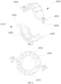
FIG. 4 is an exploded view of a bracket structure in some embodiments. -
FIG. 5 is an exploded view of a bearing seat in some embodiments. -
FIG. 6 is a schematic view of an assembly of a bearing seat in some embodiments. -
FIG. 7 is a schematic view of a bracket in some embodiments. -
FIG. 8 is a partially exploded view of a bracket structure in some embodiments. -
FIG. 9 is a schematic view of a support plate in some embodiments. - Reference numerals are explained as follows:
-
centrifugal wind wheel 1000, firstcentrifugal wind wheel 1100, secondcentrifugal wind wheel 1200, thirdcentrifugal wind wheel 1300; -
motor 2000,motor body 2100,rotation shaft 2200; -
electric control box 3000; -
bracket structure 4000; -
bracket 4100,cavity 4110, opening 4120; -
bearing seat 4200,lower bearing seat 4210,upper bearing seat 4220,flange 4230,groove 4240,mounting cavity 4250; - bearing 4300;
-
transmission shaft 4400; - bearing
rubber ring 4500; -
fastener 4600; -
first drain tray 5100,second drain tray 5200,support plate 5300, inclinedsurface 5310,air collection cavity 5400; - draining
pump 6100; -
housing 7000,top cover 7100; -
evaporator 8000. - Implementation, functional features, and advantages of the objectives of the present disclosure are further described in conjunction with the embodiments and with reference to the accompanying drawings.
- Technical solutions of the present disclosure will be described clearly and completely below in combination with accompanying drawings in embodiments of the present disclosure. Obviously, the described embodiments are only a part of the embodiments of the present disclosure, rather than all embodiments of the present disclosure. Based on the embodiments of the present disclosure, other embodiments obtained by those skilled in the art without creative efforts shall fall within scope of the present disclosure.
- It should be noted that, directional indication (such as up, down, left, right, front, rear, etc.) in the embodiments of the present disclosure is only configured to explain a relative position relationship, a motion situation, etc. between components in a certain specific posture (as illustrated in the drawings). When the specific posture changes, the directional indication also changes accordingly.
- In the present disclosure, unless otherwise clearly specified and limited, terms such as "connect", "fix" and the like should be understood in a broad sense. For example, unless otherwise clearly limited, "fix" may be a fixed connection or a detachable connection or a connection as one piece; a mechanical connection or an electrical connection; a direct connection or an indirect connection through an intermediate; internal communication of two components or an interaction relationship between two components. For those skilled in the art, specific meanings of the above-mentioned terms in the present disclosure can be understood according to specific circumstances.
- In addition, descriptions related to the terms "first" and "second" in the present disclosure are only used for descriptive purposes, and cannot be understood as indicating or implying relative importance or implicitly indicating the number of indicated technical features. Therefore, the features associated with "first" and "second" may explicitly or implicitly comprise at least one of the features. In addition, the technical solutions between the various embodiments may be combined with each other, but must be based on the ability of those of ordinary skill in the art to implement them. In addition, when the combination of the technical solutions is contradictory or cannot be implemented, it should be regarded that the combination of the technical solutions does not exist, nor is within the scope of the present disclosure.
- The present disclosure provides an air-conditioning indoor unit.
- As illustrated in
FIG. 1 andFIG. 2 , in some embodiments of the present disclosure, the air-conditioning indoor unit comprises acentrifugal wind wheel 1000, amotor 2000, anelectric control box 3000, and anevaporator 8000. - The
motor 2000 is drivingly connected to thecentrifugal wind wheel 1000, and thecentrifugal wind wheel 1000 rotates under action of themotor 2000. In this way, a predetermined negative pressure is formed inside the air-conditioning indoor unit. Therefore, indoor air can be sucked. In general, the air-conditioning indoor unit has a predetermined size, and thus is formed with a plurality of air outlets. A plurality ofcentrifugal wind wheels 1000 are provided, i.e., at least twocentrifugal wind wheels 1000 are provided. Each air outlet is correspondingly provided with onecentrifugal wind wheel 1000, and the indoor air sucked by thecentrifugal wind wheel 1000 is outputted through the air outlet. In order to make consistent air output through each air outlet and avoid inconsistencies in air output sizes of different air outlets, in this embodiment, by configuring themotor 2000 to be drivingly connected to the plurality ofcentrifugal wind wheels 1000, i.e., through driving of asame motor 2000, power is transmitted to all thecentrifugal wind wheels 1000, making rotational speeds of the centrifugal wind wheels almost same and formed suction forces also almost same. In this way, wind speeds outputted through the air outlet are almost same, and a problem of a partially excessive air volume or partially insufficient air volume is avoided. It can be understood that, as long as the transmission of power to eachcentrifugal wind wheel 1000 can be realized, a connection between themotor 2000 and the plurality ofcentrifugal wind wheels 1000 may be implemented in various ways, such as a direct drive connection or an indirect drive connection. - When the
centrifugal wind wheel 1000 sucks air under the action of themotor 2000, the air needs to flow through theevaporator 8000 and exchanges with a refrigerant in theevaporator 8000. In this way, cooling of the air is realized. In order to improve a heat exchange capacity of theevaporator 8000, theevaporator 8000 is designed to be inclined. In an exemplary embodiment of the present disclosure, a height direction of the air-conditioning indoor unit (such as a vertical direction) is taken as an example, and a top of theevaporator 8000 may be considered to rotate downwards by a predetermined angle around a bottom of theevaporator 8000. In this way, theevaporator 8000 is formed in an inclined configuration. It can be understood that when a thickness of the air-conditioning indoor unit is constant, theevaporator 8000 is designed to be inclined, which can increase an area of theevaporator 8000, thereby increasing a heat exchange area. In this way, heat exchange efficiency can be improved. In another exemplary embodiment of the present disclosure, in order to balance the heat exchange efficiency and the thickness of the air-conditioning indoor unit, an angle between theevaporator 8000 and a horizontal plane may be designed to range from 48° to 58°, and may be 48°, 51°, 53°, 58°, and the like. For example, theevaporator 8000 may be designed to form an angle of 37° with the height direction of the air-conditioning indoor unit. When a bottom surface of the air-conditioning indoor unit is horizontal, an angle between theevaporator 8000 and the bottom surface of the air-conditioning indoor unit is 53°. At this angle, optimum heat exchange efficiency may be achieved without a too large thickness of the air-conditioning indoor unit. - In addition, in order to ensure normal operation of the
centrifugal wind wheel 1000, themotor 2000, and theevaporator 8000, the air-conditioning indoor unit needs to be provided with anelectric control box 3000. Theelectric control box 3000 needs to be electrically connected to thecentrifugal wind wheel 1000, themotor 2000, and the like, and also needs to be electrically connected to an air-conditioning outdoor unit, to ensure normal operation of the entire air conditioning system. In order to ensure that theevaporator 8000 and theelectric control box 3000 do not interfere with each other, theelectric control box 3000 and theelectric control box 3000 are disposed in two different directions. For example, theelectric control box 3000 is disposed in an axial direction of thecentrifugal wind wheel 1000. It can be understood that thecentrifugal wind wheel 1000 has a rotation axis during its rotation, and an extending direction of the rotation axis of thecentrifugal wind wheel 1000 is the axial direction of thecentrifugal wind wheel 1000. Theevaporator 8000 is disposed in a radial direction of thecentrifugal wind wheel 1000, and the radial direction of thecentrifugal wind wheel 1000 is perpendicular to the axial direction of thecentrifugal wind wheel 1000. For example, as illustrated inFIG. 1 , theevaporator 8000 is located at the rear of thecentrifugal wind wheel 1000. Air flows through theevaporator 8000 from rear to front, and then is sucked by thecentrifugal wind wheel 1000 to be discharged forwards to an indoor space. Therefore, the air flowing through theevaporator 8000 is difficult to be in contact with theelectric control box 3000, and condensed water carried by the air is also difficult to reach theelectric control box 3000, to prevent theelectric control box 3000 from being damaged by moisture. - In addition, when the
centrifugal wind wheel 1000 is mounted, the air-conditioning indoor unit needs to have a predetermined space provided for realizing the suction of air by thecentrifugal wind wheel 1000, and thus a space where thecentrifugal wind wheel 1000 is located is large. In this way, theelectric control box 3000 can be arranged more flexibly by disposing theelectric control box 3000 in the axial direction of thecentrifugal wind wheel 1000. Since theelectric control box 3000 needs to be electrically connected to other components, theelectric control box 3000 has wiring running outwards. At this time, the wiring has no interference with a refrigerant pipeline of theevaporator 8000, preventing an internal structure from appearing overly cluttered. In this way, the internal structure of the air-conditioning indoor unit appears neater, facilitating mounting and maintenance. - According to the technical solutions, by providing the plurality of
centrifugal wind wheels 1000 and driving the plurality ofcentrifugal wind wheels 1000 by thesame motor 2000, when the size of the air-conditioning indoor unit is large, a constant air volume may be outputted. Theelectric control box 3000 is located in the axial direction of thecentrifugal wind wheel 1000 and far away from theevaporator 8000, to prevent theelectric control box 3000 from being splashed by the condensed water. In addition, since a large space is formed when thecentrifugal wind wheel 1000 is provided, theelectric control box 3000 is located in the axial direction of thecentrifugal wind wheel 1000 to more facilitate an arrangement of theelectric control box 3000. Theevaporator 8000 is disposed obliquely relative to the air-conditioning indoor unit. In this way, the thickness of the air-conditioning indoor unit can be reduced. Moreover, a condensation area can be increased, and the heat exchange efficiency can be improved. - In another exemplary embodiment of the present disclosure, as illustrated in
FIG. 1 to FIG. 3 , in some embodiments of the present disclosure, threecentrifugal wind wheels 1000 are provided for illustration. In the threecentrifugal wind wheels 1000, there are a thirdcentrifugal wind wheel 1300, a secondcentrifugal wind wheel 1200, and a firstcentrifugal wind wheel 1100, respectively. The thirdcentrifugal wind wheel 1300, the secondcentrifugal wind wheel 1200, and the firstcentrifugal wind wheel 1100 are arranged sequentially. The arrangement of the three centrifugal wind wheels 1000 (1100/1200/1300) makes the air-conditioning indoor unit have a wide range of air discharge effects, and does not make a product of the air-conditioning indoor unit excessively heavy simultaneously. - In order to realize driving of the three
centrifugal wind wheels 1000, themotor 2000 is used to cooperate with atransmission shaft 4400. In an exemplary embodiment of the present disclosure, themotor 2000 has two parts that are amotor body 2100 and arotation shaft 2200, respectively. Therotation shaft 2200 passes through themotor body 2100, and themotor body 2100 drives therotation shaft 2200 to rotate. When therotation shaft 2200 is directly connected to each of the threecentrifugal wind wheels 1000, a length of therotation shaft 2200 needs to be set overlong. Anoverlong rotation shaft 2200 adversely affects a structural strength of therotation shaft 2200. In this way, differences in torques borne by various parts in a length direction of therotation shaft 2200 may be generated, and fracture of therotation shaft 2200 may occur under driving of themotor body 2100 and under action of thecentrifugal wind wheel 1000. Therefore, thetransmission shaft 4400 is provided to be connected to therotation shaft 2200. - In an exemplary embodiment of the present disclosure, the
rotation shaft 2200 passes through themotor body 2100, and therotation shaft 2200 has one end exposed at one side of themotor body 2100 and another end exposed at another side of themotor body 2100. In this way, one end of therotation shaft 2200 can be connected to the firstcentrifugal wind wheel 1100, i.e., the firstcentrifugal wind wheel 1100 is relatively fixed to one end of therotation shaft 2200. Therefore, the firstcentrifugal wind wheel 1100 can be driven to rotate when therotation shaft 2200 rotates. The other end of therotation shaft 2200 is connected to thetransmission shaft 4400, i.e., therotation shaft 2200 realizes power transmission to thetransmission shaft 4400, and thetransmission shaft 4400 is rotatable with the rotation of therotation shaft 2200. It can be understood that a connection between therotation shaft 2200 and thetransmission shaft 4400 may be realized by a coupling to transmit power. Thetransmission shaft 4400 passes and is fixed along rotation centers of the secondcentrifugal wind wheel 1200 and the thirdcentrifugal wind wheel 1300. When thetransmission shaft 4400 rotates, rotation of the secondcentrifugal wind wheel 1200 and the thirdcentrifugal wind wheel 1300 may be realized. By configuring thetransmission shaft 4400 to cooperate with themotor 2000, a problem of insufficient structural strength caused by the overlong length of therotation shaft 2200 is avoided, and the driving of the plurality ofcentrifugal wind wheels 1000 can be realized in cooperation with themotor 2000 simultaneously. - In another exemplary embodiment of the present disclosure, as illustrated in
FIG. 2 , in some embodiments of the present disclosure, in order to utilize the space of the air-conditioning indoor unit to the maximum extent, themotor 2000 is disposed between the secondcentrifugal wind wheel 1200 and the firstcentrifugal wind wheel 1100. In an exemplary embodiment of the present disclosure, thecentrifugal wind wheel 1000 needs to perform suction in the axial direction of thecentrifugal wind wheel 1000 during operation, and the air enters thecentrifugal wind wheel 1000 in the axial direction of thecentrifugal wind wheel 1000. Therefore, adjacentcentrifugal wind wheels 1000 are spaced apart from each other by a predetermined distance. At this time, by placing themotor 2000 between the firstcentrifugal wind wheel 1100 and the secondcentrifugal wind wheel 1200, a larger space occupied by disposing themotor 2000 outside the firstcentrifugal wind wheel 1100 may be avoided. When themotor 2000 is disposed between the secondcentrifugal wind wheel 1000 and the firstcentrifugal wind wheel 1100, themotor 2000 does not occupy all axial spaces of thecentrifugal wind wheel 1000, and thus does not influence air suction of thecentrifugal wind wheel 1000. In addition, since threecentrifugal wind wheels 1000 are comprised in this embodiment, when themotor 2000 is disposed between the firstcentrifugal wind wheel 1100 and the secondcentrifugal wind wheel 1200, a distance of themotor 2000 from eachcentrifugal wind wheel 1000 is appropriate, making the driving of themotor 2000 more efficient. - In another exemplary embodiment of the present disclosure, as illustrated in
FIG. 2 andFIG. 3 , when thetransmission shaft 4400 and therotation shaft 2200 are connected, thetransmission shaft 4400 is equivalent to forming a cantilever structure. In order to make the rotation of thetransmission shaft 4400 smoother, the air-conditioning indoor unit in this embodiment further comprises abracket structure 4000 for supporting thetransmission shaft 4400, which plays a role of supporting thetransmission shaft 4400. In addition, by disposing thebracket structure 4000 between the thirdcentrifugal wind wheel 1300 and the secondcentrifugal wind wheel 1200, a space between the thirdcentrifugal wind wheel 1300 and the secondcentrifugal wind wheel 1200 may be fully utilized, and thebracket structure 4000 is closer to a middle part of thetransmission shaft 4400. In this way, thetransmission shaft 4400 is supported more effectively, making operation of thetransmission shaft 4400 more stable. - As illustrated in
FIG. 4 andFIG. 7 , in some embodiments of the present disclosure, thebracket structure 4000 comprises abracket 4100, abearing seat 4200, and abearing 4300. Through cooperation of thebracket 4100, the bearingseat 4200, thebearing 4300, and thetransmission shaft 4400, mounting difficulty of thetransmission shaft 4400 is reduced, mounting efficiency is improved, and effective supporting and positioning of thetransmission shaft 4400 are realized. - In an exemplary embodiment of the present disclosure, the supporting of the
transmission shaft 4400 is realized by thebracket 4100. For example, thebracket 4100 is mounted to the second drain tray 5200 (described in detail below). In order to cause thetransmission shaft 4400 to smoothly rotate, thetransmission shaft 4400 needs to cooperate with thebearing seat 4200 and thebearing 4300, and thebearing seat 4200 and thebearing 4300 are parts used as a set. Thebearing 4300 is a part capable of supporting the rotation of thetransmission shaft 4400 and reducing a resistance to the rotation of thetransmission shaft 4400. For example, thebearing 4300 comprises an inner ring, an outer ring, and balls located between the inner ring and the outer ring. Thetransmission shaft 4400 passes through thebearing 4300, i.e., thetransmission shaft 4400 passes through the inner ring and is fixed to the inner ring. When thetransmission shaft 4400 rotates, the inner ring may be driven to rotate relative to the outer ring, and the outer ring is fixed to thebearing seat 4200 and relatively fixed to thebearing seat 4200. The bearingseat 4200 is a part for supporting thebearing 4300 and ensuring stability of thebearing 4300 during the rotation of thetransmission shaft 4400. For example, the outer ring of thebearing 4300 is fixed to thebearing seat 4200. In order to conveniently combine thebearing seat 4200 and thebracket 4100, thebracket 4100 is provided with acavity 4110 and anopening 4120. Theopening 4120 is in communication with thecavity 4110, and is formed in a radial direction of thecavity 4110. It can be understood that the radial direction here is perpendicular to an axial direction of thecavity 4110. The axial direction of thecavity 4110 is an extending direction of thetransmission shaft 4400 when thetransmission shaft 4400 is mounted to thebracket 4100. In this way, the arrangement of thecavity 4110 and theopening 4120 makes thebracket 4100 provided with a non-closed arc-shaped structure. For example, when thebracket 4100 is vertically fixed and mounted to the air-conditioning indoor unit, thecavity 4110 forms anupward opening 4120. In this way, the bearingseat 4200 can pass through theopening 4120 from top to bottom and be embedded into thecavity 4110, to realize mounting of thebearing seat 4200 with thebracket 4100. Because of occurrence of theopening 4120, during the mounting of thebearing seat 4200, the bearingseat 4200 enters thecavity 4110 from theopening 4120 and gradually approaches a wall of thecavity 4110. In this way, mounting efficiency of bearingseat 4200 can be effectively improved. Moreover, when thebearing seat 4200 is mounted to thebracket 4100, the bearingseat 4200 settles onto thebracket 4100 under action of gravity, thus providing an initial positioning that makes subsequent fastening operations more convenient. When thecavity 4110 has noopening 4120, thecavity 4110 causes thebracket 4100 to be in a closed ring shape. In this way, it is necessary to repeatedly align thebearing seat 4200 when thebearing seat 4200 is mounted, which reduces the mounting efficiency. - By providing the
bracket 4100, the bearingseat 4200, thebearing 4300, and thetransmission shaft 4400, thebearing 4300 is disposed in thebearing seat 4200, thetransmission shaft 4400 passes through thebearing 4300, and thebracket 4100 is provided with thecavity 4110 and theopening 4120 in communication with thecavity 4110. In this way, the bearingseat 4200 can be embedded into thecavity 4110 from theopening 4120 to be mounted to the bracket 4100.The occurrence of theopening 4120 makes the mounting of thebearing seat 4200 more convenient, thus realizing the supporting of thetransmission shaft 4400 and greatly improving mounting efficiency of thetransmission shaft 4400. - As illustrated in
FIG. 5 and FIG. 6 , in some embodiments of the present disclosure, the bearingseat 4200 comprises anupper bearing seat 4220 and alower bearing seat 4210. Theupper bearing seat 4220 and thelower bearing seat 4210 are combined to form theentire bearing seat 4200 through a mutual connection of theupper bearing seat 4220 and thelower bearing seat 4210. After theupper bearing seat 4220 and thelower bearing seat 4210 are connected to each other, a mountingcavity 4250 may be defined and is configured to realize the mounting of thebearing 4300. By designing thebearing seat 4200 as theupper bearing seat 4220 and thelower bearing seat 4210, the bearing is more convenient to be mounted into the bearingseat 4200. - In an exemplary embodiment of the present disclosure, since it is necessary to prevent the
bearing 4300 from being disengaged from the bearingseat 4200 after thebearing 4300 is mounted to thebearing seat 4200, when thebearing seat 4200 is designed as theupper bearing seat 4220 and thelower bearing seat 4210, theupper bearing seat 4220 and thelower bearing seat 4210 are docked together to cover thebearing 4300, which can form position-limit and fixation of thebearing 4300, with a simpler and more convenient connection manner. There are various manners when thebearing seat 4200 is mounted to thebracket 4100. For example, thelower bearing seat 4210 is first mounted to thebracket 4100, then thetransmission shaft 4400 mounted with thebearing 4300 is moved as a whole towards thebracket 4100 until thebearing 4300 is supported on thelower bearing seat 4210, and then theupper bearing seat 4220 is sleeved over thebearing 4300 and connected to thelower bearing seat 4210. In this way, the supporting and positioning of thetransmission shaft 4400 can be realized. It can also be that thebearing 4300 may be first fixed to thetransmission shaft 4400, then theupper bearing seat 4220 and thelower bearing seat 4210 collectively cover thebearing 4300 for fixing, and then thetransmission shaft 4400, thebearing 4300, and thebearing seat 4200 as a whole are moved towards thebracket 4100 until thebearing seat 4200 is mounted into thecavity 4110 through theopening 4120. No matter which manner is chosen, through the combination of theupper bearing seat 4220 and thelower bearing seat 4210, mounting efficiency between thebearing seat 4200 and thebearing 4300 is improved. - In another exemplary embodiment of the present disclosure, as illustrated in
FIG. 5 and FIG. 6 , in order to realize fastening between thebearing seat 4200 and thebracket 4100, the bearingseat 4200 is connected to a periphery of theopening 4120, i.e., a portion of thebracket 4100 closing to theopening 4120. The portion is located outside thecavity 4110, which does not interfere with embedding of thebearing seat 4200 into thecavity 4110. - For example, as illustrated in
FIG. 5 and FIG. 6 , after thebearing seat 4200 is mounted to thebracket 4100, in order to realize connection and fastening between thebearing seat 4200 and thebracket 4100, theupper bearing seat 4220 and thelower bearing seat 4210 are each provided with aflange 4230, and theflange 4230 abuts against the periphery of theopening 4120. In this way, the fastening between thebearing seat 4200 and thebracket 4100 can be conveniently realized by theflange 4230 and the periphery of theopening 4120. - In an exemplary embodiment of the present disclosure, when the
bearing seat 4200 is mounted to thebracket 4100, thelower bearing seat 4210 is embedded in thecavity 4110. It can be that thelower bearing seat 4210 is entirely embedded in thecavity 4110 or partially embedded in thecavity 4110. Two opposite ends of thelower bearing seat 4210 are provided withflanges 4230, and theflanges 4230 of thelower bearing seat 4210 are overlapped at the periphery of theopening 4120, i.e., overlapped at the portion of thebracket 4100 closing to theopening 4120. - The same applies to the upper bearing seat 4220.Two opposite ends of the
upper bearing seat 4220 are also provided withflanges 4230. When theupper bearing seat 4220 is connected to thelower bearing seat 4210, theflanges 4230 of theupper bearing seat 4220 are aligned with theflanges 4230 of thelower bearing seat 4210. In this way, theflanges 4230 of theupper bearing seat 4220, theflanges 4230 of thelower bearing seat 4210, and the periphery of theopening 4120 only need to be fastened in this case, to achieve the fastening between thebracket 4100 and thebearing seat 4200, thereby realizing the positioning and supporting of thetransmission shaft 4400. Since theflange 4230 of theupper bearing seat 4220 and theflange 4230 of thelower bearing seat 4210 extend away from the mountingcavity 4250, connections of theflanges 4230 do not affect the mounting of thebearing 4300 to the mountingcavity 4250. Moreover, through the arrangement of theflange 4230, the bearingseat 4200 when located on thebracket 4100 may play a predetermined supporting and positioning effect, making the subsequent fastening operations more convenient. - In another exemplary embodiment of the present disclosure, as illustrated in
FIG. 5 and FIG. 6 , in some embodiments of the present disclosure, a fastening connection between thebracket 4100 and thebearing seat 4200 is realized by afastener 4600. In this embodiment, thefastener 4600 is a threaded fastener, such as a bolt, a screw, or the like. Theflange 4230 of theupper bearing seat 4220, theflange 4230 of thelower bearing seat 4210, and the periphery of theopening 4120 are provided with a mounting hole, respectively. Thefastener 4600 sequentially passes through mounting holes of various components for fastening the components. In this way, the fastening connection between thebearing seat 4200 and thebracket 4100 is realized. Since thefastener 4600 passes through theflange 4230 of theupper bearing seat 4220 and theflange 4230 of thelower bearing seat 4210, fastening of thebearing 4300 is realized between theupper bearing seat 4220 and thelower bearing seat 4210, without interference with thebearing 4300 during tightly screwing of theflange 4230. Therefore, fixation among thebracket 4100, the bearingseat 4200, thebearing 4300, and thetransmission shaft 4400 is conveniently realized. - As illustrated in
FIG. 4 andFIG. 8 , in some embodiments of the present disclosure, thebracket structure 4000 further comprises a bearingrubber ring 4500. The bearingrubber ring 4500 has a predetermined elasticity. For example, the bearingrubber ring 4500 is made of rubber to form a closed ring shape. During a process where thetransmission shaft 4400 drives thecentrifugal wind wheel 1000 to rotate, a predetermined vibration may occur. In order to prevent the vibration from being transmitted to thebracket 4100 to cause noise, the bearingrubber ring 4500 is provided and is of a hollow ring structure as a whole. Thebearing 4300 is placed in the bearingrubber ring 4500, i.e., the bearingrubber ring 4500 surrounds a circumferential direction of thebearing 4300 to cover thebearing 4300, and the bearingrubber ring 4500 is mounted in thebearing seat 4200, i.e., the bearingrubber ring 4500 is provided between thebearing 4300 and thebearing seat 4200 for providing cushioning. When the vibration is transmitted from thetransmission shaft 4400 to thebearing 4300, the bearingrubber ring 4500 may absorb energy of the vibration, preventing the energy from continuing to be transmitted to thebearing seat 4200 and further transmitted to thebracket 4100. In this way, the generation of noise is avoided. - In another exemplary embodiment of the present disclosure, as illustrated in
FIG. 5 , in order to more facilitate the fixation of the bearingrubber ring 4500 and prevent the bearingrubber ring 4500 from being disengaged from the bearingseat 4200, agroove 4240 is disposed on thebearing seat 4200, and extends around an inner side of thebearing seat 4200. In this way, a peripheral portion of the bearingrubber ring 4500 can be embedded in thegroove 4240, to prevent the bearingrubber ring 4500 from being disengaged from the bearingseat 4200 in the axial direction of thebearing seat 4200. In an exemplary embodiment of the present disclosure, when thebearing seat 4200 comprises theupper bearing seat 4220 and thelower bearing seat 4210, theupper bearing seat 4220 and thelower bearing seat 4210 have groove structures, respectively. Theintegrated groove 4240 is formed by mutual docking of theupper bearing seat 4220 and thelower bearing seat 4210, which can realize covering of the bearingrubber ring 4500. - As illustrated in
FIG. 2 , in some embodiments of the present disclosure, the air-conditioning indoor unit further comprises afirst drain tray 5100. Thefirst drain tray 5100 is a structure for collecting the condensed water and is disposed below theevaporator 8000. When the air flows through and exchanges heat with theevaporator 8000, the condensed water is generated on a surface of theevaporator 8000. The condensed water flows to thefirst drain tray 5100 along theevaporator 8000 under the action of gravity, to prevent the condensed water from overflowing to outside of the air-conditioning indoor unit. In an exemplary embodiment of the present disclosure, the air-conditioning indoor unit has a chassis structure, and thefirst drain tray 5100 may be fixed to the chassis structure. When theevaporator 8000 is mounted, the bottom of theevaporator 8000 abuts against thefirst drain tray 5100. In this way, sealing between theevaporator 8000 and thefirst drain tray 5100 is realized, and the air is prevented from passing between the drain tray and theevaporator 8000 without performing heat exchange. In addition, in order to realize sealing of the top of theevaporator 8000, the top of theevaporator 8000 and atop cover 7100 of the air-conditioning indoor unit abut against each other. In this way, the air is prevented from passing between theevaporator 8000 and thetop cover 7100 of the air-conditioning indoor unit without performing heat exchange. Sealing of upper and lower positions of theevaporator 8000 is realized through the cooperation of thefirst drain tray 5100 and thetop cover 7100 of the air-conditioning indoor unit. - In another exemplary embodiment of the present disclosure, in order to realize sealing of two opposite ends of the
evaporator 8000, asupport plate 5300 is provided. It can be understood that, with reference toFIG. 2 , the two opposite ends of theevaporator 8000 are left and right ends. Thesupport plate 5300 respectively abuts against and is fixed to the two opposite ends of theevaporator 8000, and is mounted on thefirst drain tray 5100. In this way, sealing of the two opposite ends of theevaporator 8000 can be realized. Moreover, anair collection cavity 5400 is enclosed by thesupport plate 5300, thefirst drain tray 5100, thetop cover 7100 of the air-conditioning indoor unit, and the air inlet end of theevaporator 8000. When the air flows into theair collection cavity 5400, the air is gathered and prevented from overflowing. In this way, the air passes through theevaporator 8000 more efficiently, and the heat exchange efficiency is improved. - In another exemplary embodiment of the present disclosure, as illustrated in
FIG. 2 andFIG. 9 , in order to realize a demand for inclined mounting of theevaporator 8000, thesupport plate 5300 has an inclined surface in an inclined state formed thereon. In this way, theinclined surface 5310 of thesupport plate 5300 can support an end portion of theevaporator 8000 to make theevaporator 8000 inclined. A weight of theevaporator 8000 is supported by thesupport plate 5300. Through a support effect, structural strength requirements for the fastener being connected to theevaporator 8000 and thesupport plate 5300 are reduced. Moreover, a predetermined supporting and positioning effect is achieved when theevaporator 8000 is supported by thesupport plate 5300, which is more convenient to perform fastening operations on thesupport plate 5300 and theevaporator 8000 through the fastener. - As illustrated in
FIG. 2 , in some embodiments of the present disclosure, in order to realize discharge of the collected condensed water, adraining pump 6100 is provided. For example, as described above, thefirst drain tray 5100 is provided below theevaporator 8000 for collecting the condensed water flowing down from theevaporator 8000. At this time, forcible discharge of the condensed water may be realized through pumping and discharging effects of thedraining pump 6100. In order to facilitate the arrangement of thedraining pump 6100, the drainingpump 6100 and theelectric control box 3000 are arranged in a first direction, and the first direction herein is a direction from thecentrifugal wind wheel 1000 to theevaporator 8000. For example, referring to an orientation inFIG. 2 , the first direction is a front-rear direction. Thecentrifugal wind wheel 1000 is disposed in the front, theevaporator 8000 is disposed in the rear, theelectric control box 3000 is disposed in the front and located at one side of the centrifugal wind wheel 1000 (at a left side of the centrifugal wind wheel 1000), and thedraining pump 6100 is disposed at the rear of theelectric control box 3000 and located at one side of theevaporator 8000. In this way, it is convenient to wiring design between thedrainage pump 6100 and theelectric control box 3000, making the wiring simpler. Theelectric control box 3000, thedrainage pump 6100, and other parts are disposed together in a region where theelectric control box 3000, thedrainage pump 6100, and other parts are close to each other, which is more convenient for subsequent maintenance and treatment. - As described above, the
first drain tray 5100 is provided below theevaporator 8000, and the condensed water generated when the air flows through theevaporator 8000 flows to thefirst drain tray 5100. In order to prevent the condensed water from being sprayed into an indoor environment along with flowing of the air, as illustrated inFIG. 2 , theevaporator 8000 is disposed on an air inlet path of thecentrifugal wind wheel 1000. It can be understood that the air inlet path of thecentrifugal wind wheel 1000 is a path through which the air flows to an inlet of thecentrifugal wind wheel 1000. For example, inFIG. 2 , theevaporator 8000 is located at the rear of thecentrifugal wind wheel 1000. In this way, when the air passes through theevaporator 8000 and takes away the condensed water, the condensed water may collide with thecentrifugal wind wheel 1000 and be re-collected under obstruction of thecentrifugal wind wheel 1000. Therefore, when thesecond drain tray 5200 is provided below thecentrifugal wind wheel 1000, the condensed water obstructed by thecentrifugal wind wheel 1000 is accumulated on thesecond drain tray 5200, and thesecond drain tray 5200 may be configured to be in communication with thefirst drain tray 5100. For example, thesecond drain tray 5200 is disposed at a higher position. In this way, water in thesecond drain tray 5200 may flow to thefirst drain tray 5100 under the action of gravity. The drainingpump 6100 as mentioned above is disposed in thefirst drain tray 5100 to pump and discharge the condensed water in thefirst drain tray 5100 to the outside. When thebracket 4100 and themotor 2000 are mounted to thesecond drain tray 5200, thesecond drain tray 5200 provides a mounting base, which ensures a height at which thebracket 4100 and themotor 2000 are mounted, ensuring an effective connection between themotor 2000 and thetransmission shaft 4400. - As illustrated in
FIG. 1 , in some embodiments of the present disclosure, the air-conditioning indoor unit further comprises ahousing 7000 that defines an outer surface of the air-conditioning indoor unit. Components such as themotor 2000, thecentrifugal wind wheel 1000, theevaporator 8000, and theelectric control box 3000 are mounted in thehousing 7000, and in particular, theelectric control box 3000 is built in. In this way, an aesthetic degree of the whole machine can be improved. - The present disclosure also relates to an air conditioner. The air conditioner comprises the aforementioned air-conditioning indoor unit. In an exemplary embodiment of the present disclosure, the air-conditioning outdoor unit and the air-conditioning indoor unit are connected to realize refrigerant circulation. A structure of the air-conditioning indoor unit of this embodiment refers to the embodiments described above. Since the air conditioner adopts the technical solutions of the embodiments described above, the air conditioner at least has the beneficial effects brought by the technical solutions of the embodiments described above, and details are omitted herein.
- The above is only some specific embodiments of the present disclosure, and does not limit the patent scope of the present disclosure. Any equivalent structural transformation made by using the contents of the specification of the present disclosure and the accompanying drawings under the concept of the present disclosure, or directly/indirectly applied to other related technical fields, is comprised in the patent protection scope of the present disclosure.
Claims (18)
- An air-conditioning indoor unit, comprising:a plurality of centrifugal wind wheels;a motor drivingly connected to a plurality of the centrifugal wind wheels;an electric control box disposed in an axial direction of the centrifugal wind wheel; andan evaporator disposed in a radial direction of the centrifugal wind wheel and obliquely disposed relative to a height direction of the air-conditioning indoor unit.
- The air-conditioning indoor unit according to claim 1, further comprising a transmission shaft, wherein:the centrifugal wind wheels comprise three centrifugal wind wheels, the three centrifugal wind wheels being a first centrifugal wind wheel, a second centrifugal wind wheel, and a third centrifugal wind wheel that are arranged sequentially; andthe motor comprises a motor body and a rotation shaft, the rotation shaft having an end connected to the first centrifugal wind wheel and an other end connected to the transmission shaft, and the transmission shaft being connected to the second centrifugal wind wheel and the third centrifugal wind wheel.
- The air-conditioning indoor unit according to claim 2, wherein the motor is disposed between the first centrifugal wind wheel and the second centrifugal wind wheel.
- The air-conditioning indoor unit according to claim 2, further comprising a bracket structure for supporting the transmission shaft, the bracket structure being disposed between the second centrifugal wind wheel and the third centrifugal wind wheel.
- The air-conditioning indoor unit according to claim 4, wherein the bracket structure comprises:a bracket provided with a cavity and an opening in communication with the cavity, the opening being located in a radial direction of the cavity;a bearing seat mounted to the bracket by embedding into the cavity through the opening;a bearing rubber ring disposed in the bearing seat; anda bearing disposed in the bearing rubber ring, the transmission shaft passing through the bearing.
- The air-conditioning indoor unit according to claim 5, wherein the opening is located above the cavity.
- The air-conditioning indoor unit according to claim 5, wherein the bearing seat comprises a lower bearing seat and an upper bearing seat that are connected to each other, a mounting cavity for mounting the bearing being defined between the lower bearing seat and the upper bearing seat.
- The air-conditioning indoor unit according to claim 7, wherein the lower bearing seat and the upper bearing seat are connected to a periphery of the opening.
- The air-conditioning indoor unit according to claim 8, wherein the lower bearing seat and the upper bearing seat are each provided with a flange connected to the periphery of the opening.
- The air-conditioning indoor unit according to claim 9, further comprising a fastener sequentially penetrating the flange of the upper bearing seat, the flange of the lower bearing seat, and the periphery of the opening for fastening.
- The air-conditioning indoor unit according to claim 5, wherein the bearing seat is provided with a groove surrounding the bearing rubber ring, enabling the bearing rubber ring to be embedded in the groove.
- The air-conditioning indoor unit according to claim 1, further comprising a first drain tray, the evaporator being located above the first drain tray, and the evaporator having a bottom abutting against the first drain tray and a top abutting against a top cover of the air-conditioning indoor unit.
- The air-conditioning indoor unit according to claim 12, further comprising a support plate provided at each of two opposite ends of the evaporator, the support plate being supported on the first drain tray, an air collection cavity being enclosed by the first drain tray, the support plate, the evaporator, and the top cover.
- The air-conditioning indoor unit according to claim 13, wherein the support plate is provided with an inclined surface to support an end portion of the evaporator.
- The air-conditioning indoor unit according to claim 1, further comprising a draining pump, wherein:
taking a direction from the centrifugal wind wheel to the evaporator as a first direction, the electric control box and the draining pump are arranged in the first direction. - The air-conditioning indoor unit according to claim 1, further comprising a first drain tray located below the evaporator and a second drain tray located below the centrifugal wind wheel, the evaporator being located on an air inlet path of the centrifugal wind wheel.
- The air-conditioning indoor unit according to claim 1, further comprising a housing, the centrifugal wind wheels, the motor, the evaporator, and the electric control box being disposed in the housing.
- An air conditioner, comprising an air-conditioning indoor unit according to any one of claims 1 to 17.
Applications Claiming Priority (3)
| Application Number | Priority Date | Filing Date | Title |
|---|---|---|---|
| CN202223358172.5U CN219063597U (en) | 2022-12-12 | 2022-12-12 | Transmission shaft mounting structure, air conditioner indoor unit and air conditioner |
| CN202223357502.9U CN219063599U (en) | 2022-12-12 | 2022-12-12 | Air suction type air conditioner indoor unit and air conditioner |
| PCT/CN2023/114020 WO2024124947A1 (en) | 2022-12-12 | 2023-08-21 | Air conditioner indoor unit and air conditioner |
Publications (2)
| Publication Number | Publication Date |
|---|---|
| EP4484835A1 true EP4484835A1 (en) | 2025-01-01 |
| EP4484835A4 EP4484835A4 (en) | 2025-07-02 |
Family
ID=91484329
Family Applications (1)
| Application Number | Title | Priority Date | Filing Date |
|---|---|---|---|
| EP23902156.1A Pending EP4484835A4 (en) | 2022-12-12 | 2023-08-21 | INDOOR UNIT OF AN AIR CONDITIONER AND AIR CONDITIONING SYSTEM |
Country Status (4)
| Country | Link |
|---|---|
| US (1) | US20250271149A1 (en) |
| EP (1) | EP4484835A4 (en) |
| KR (1) | KR20240155303A (en) |
| WO (1) | WO2024124947A1 (en) |
Family Cites Families (11)
| Publication number | Priority date | Publication date | Assignee | Title |
|---|---|---|---|---|
| TW458258U (en) * | 2000-12-01 | 2001-10-01 | Koochingchai Pong | Improved structure for wind-wheel and wind-channel of separated air conditioner |
| TW517833U (en) * | 2002-04-24 | 2003-01-11 | Koochingchai Pong | Improved ventilating structure for wind wheel of split air conditioning and heating machine |
| KR20050117665A (en) * | 2004-06-11 | 2005-12-15 | 엘지전자 주식회사 | Indoor unit for air conditioner |
| WO2006080793A2 (en) * | 2005-01-27 | 2006-08-03 | Lg Electronics, Inc. | Indoor unit of air conditioner |
| JP6115782B2 (en) * | 2011-09-29 | 2017-04-19 | パナソニックIpマネジメント株式会社 | Air conditioner |
| CN204176767U (en) * | 2014-09-28 | 2015-02-25 | 广东美的制冷设备有限公司 | Indoor unit of wall hanging type air conditioner and air-conditioner |
| AU2016396507B2 (en) * | 2016-03-07 | 2020-03-19 | Toshiba Carrier Corporation | Air conditioner and blower device |
| CN205860403U (en) * | 2016-05-03 | 2017-01-04 | 广东美的制冷设备有限公司 | The wind guiding component of air-conditioner and air-conditioner |
| CN109882943A (en) * | 2019-03-22 | 2019-06-14 | 广东美的制冷设备有限公司 | Package AC plant |
| CN219063599U (en) * | 2022-12-12 | 2023-05-23 | 广东美的暖通设备有限公司 | Air suction type air conditioner indoor unit and air conditioner |
| CN219063597U (en) * | 2022-12-12 | 2023-05-23 | 广东美的暖通设备有限公司 | Transmission shaft mounting structure, air conditioner indoor unit and air conditioner |
-
2023
- 2023-08-21 EP EP23902156.1A patent/EP4484835A4/en active Pending
- 2023-08-21 KR KR1020247032014A patent/KR20240155303A/en active Pending
- 2023-08-21 WO PCT/CN2023/114020 patent/WO2024124947A1/en not_active Ceased
- 2023-08-21 US US18/850,575 patent/US20250271149A1/en active Pending
Also Published As
| Publication number | Publication date |
|---|---|
| WO2024124947A1 (en) | 2024-06-20 |
| US20250271149A1 (en) | 2025-08-28 |
| EP4484835A4 (en) | 2025-07-02 |
| KR20240155303A (en) | 2024-10-28 |
Similar Documents
| Publication | Publication Date | Title |
|---|---|---|
| EP4442895A1 (en) | Clothes treatment device having a heat pump drying function | |
| CN208750992U (en) | Water pan and ducted air conditioner | |
| JP7607191B2 (en) | Wall-mounted air conditioner | |
| CN114083954B (en) | A roof-mounted car air conditioner | |
| US20250271149A1 (en) | Air-conditioning indoor unit and air conditioner | |
| CN219063599U (en) | Air suction type air conditioner indoor unit and air conditioner | |
| CN214028131U (en) | Parking air conditioner | |
| CN214492456U (en) | Parking air conditioner | |
| CN214501488U (en) | Electric control box of air conditioner outdoor unit and air conditioner outdoor unit | |
| CN111509951B (en) | Frequency converter | |
| CN1188878A (en) | Integral air conditioner with motors for driving interior and exterior blowers both disposed at exterior side | |
| CN201093675Y (en) | Single centrifugal wind wheel air conditioner device | |
| CN220205919U (en) | Chassis assembly and mobile air conditioner | |
| CN220541230U (en) | Roof machine and air conditioner | |
| CN209639137U (en) | Duct machine | |
| CN216812205U (en) | Casing and box formula centrifugal fan | |
| CN214492464U (en) | Parking air conditioner | |
| CN214492459U (en) | Parking air conditioner | |
| CN219063597U (en) | Transmission shaft mounting structure, air conditioner indoor unit and air conditioner | |
| WO2024045297A1 (en) | Unitary air conditioner | |
| CN101726056A (en) | Outdoor fan of window-type air conditioner | |
| CN222793177U (en) | Front end module for a vehicle thermal management system | |
| CN214492463U (en) | Parking air conditioner | |
| CN224188683U (en) | Side-vent air conditioner | |
| CN214606986U (en) | Parking air conditioner |
Legal Events
| Date | Code | Title | Description |
|---|---|---|---|
| STAA | Information on the status of an ep patent application or granted ep patent |
Free format text: STATUS: THE INTERNATIONAL PUBLICATION HAS BEEN MADE |
|
| PUAI | Public reference made under article 153(3) epc to a published international application that has entered the european phase |
Free format text: ORIGINAL CODE: 0009012 |
|
| STAA | Information on the status of an ep patent application or granted ep patent |
Free format text: STATUS: REQUEST FOR EXAMINATION WAS MADE |
|
| 17P | Request for examination filed |
Effective date: 20240926 |
|
| AK | Designated contracting states |
Kind code of ref document: A1 Designated state(s): AL AT BE BG CH CY CZ DE DK EE ES FI FR GB GR HR HU IE IS IT LI LT LU LV MC ME MK MT NL NO PL PT RO RS SE SI SK SM TR |
|
| A4 | Supplementary search report drawn up and despatched |
Effective date: 20250602 |
|
| RIC1 | Information provided on ipc code assigned before grant |
Ipc: F24F 13/22 20060101ALI20250526BHEP Ipc: F24F 1/0059 20190101ALI20250526BHEP Ipc: F24F 1/0047 20190101ALI20250526BHEP Ipc: F24F 1/0043 20190101ALI20250526BHEP Ipc: F24F 1/0033 20190101ALI20250526BHEP Ipc: F24F 1/0022 20190101AFI20250526BHEP |
|
| GRAP | Despatch of communication of intention to grant a patent |
Free format text: ORIGINAL CODE: EPIDOSNIGR1 |
|
| STAA | Information on the status of an ep patent application or granted ep patent |
Free format text: STATUS: GRANT OF PATENT IS INTENDED |
|
| DAV | Request for validation of the european patent (deleted) | ||
| DAX | Request for extension of the european patent (deleted) | ||
| INTG | Intention to grant announced |
Effective date: 20260202 |
|
| GRAS | Grant fee paid |
Free format text: ORIGINAL CODE: EPIDOSNIGR3 |
|
| GRAA | (expected) grant |
Free format text: ORIGINAL CODE: 0009210 |
|
| STAA | Information on the status of an ep patent application or granted ep patent |
Free format text: STATUS: THE PATENT HAS BEEN GRANTED |