EP4484809A1 - Flapper valve with common rotational direction - Google Patents
Flapper valve with common rotational direction Download PDFInfo
- Publication number
- EP4484809A1 EP4484809A1 EP24185721.8A EP24185721A EP4484809A1 EP 4484809 A1 EP4484809 A1 EP 4484809A1 EP 24185721 A EP24185721 A EP 24185721A EP 4484809 A1 EP4484809 A1 EP 4484809A1
- Authority
- EP
- European Patent Office
- Prior art keywords
- flapper
- valve
- portions
- flapper valve
- set forth
- Prior art date
- Legal status (The legal status is an assumption and is not a legal conclusion. Google has not performed a legal analysis and makes no representation as to the accuracy of the status listed.)
- Pending
Links
Images


Classifications
-
- F—MECHANICAL ENGINEERING; LIGHTING; HEATING; WEAPONS; BLASTING
- F04—POSITIVE - DISPLACEMENT MACHINES FOR LIQUIDS; PUMPS FOR LIQUIDS OR ELASTIC FLUIDS
- F04B—POSITIVE-DISPLACEMENT MACHINES FOR LIQUIDS; PUMPS
- F04B53/00—Component parts, details or accessories not provided for in, or of interest apart from, groups F04B1/00 - F04B23/00 or F04B39/00 - F04B47/00
- F04B53/10—Valves; Arrangement of valves
- F04B53/1037—Flap valves
- F04B53/104—Flap valves the closure member being a rigid element oscillating around a fixed point
- F04B53/1045—Flap valves the closure member being a rigid element oscillating around a fixed point the valve being formed by two elements
-
- B—PERFORMING OPERATIONS; TRANSPORTING
- B64—AIRCRAFT; AVIATION; COSMONAUTICS
- B64D—EQUIPMENT FOR FITTING IN OR TO AIRCRAFT; FLIGHT SUITS; PARACHUTES; ARRANGEMENT OR MOUNTING OF POWER PLANTS OR PROPULSION TRANSMISSIONS IN AIRCRAFT
- B64D13/00—Arrangements or adaptations of air-treatment apparatus for aircraft crew or passengers, or freight space
- B64D13/02—Arrangements or adaptations of air-treatment apparatus for aircraft crew or passengers, or freight space the air being pressurised
-
- F—MECHANICAL ENGINEERING; LIGHTING; HEATING; WEAPONS; BLASTING
- F01—MACHINES OR ENGINES IN GENERAL; ENGINE PLANTS IN GENERAL; STEAM ENGINES
- F01D—NON-POSITIVE DISPLACEMENT MACHINES OR ENGINES, e.g. STEAM TURBINES
- F01D17/00—Regulating or controlling by varying flow
- F01D17/10—Final actuators
- F01D17/12—Final actuators arranged in stator parts
- F01D17/14—Final actuators arranged in stator parts varying effective cross-sectional area of nozzles or guide conduits
- F01D17/148—Final actuators arranged in stator parts varying effective cross-sectional area of nozzles or guide conduits by means of rotatable members, e.g. butterfly valves
-
- F—MECHANICAL ENGINEERING; LIGHTING; HEATING; WEAPONS; BLASTING
- F16—ENGINEERING ELEMENTS AND UNITS; GENERAL MEASURES FOR PRODUCING AND MAINTAINING EFFECTIVE FUNCTIONING OF MACHINES OR INSTALLATIONS; THERMAL INSULATION IN GENERAL
- F16K—VALVES; TAPS; COCKS; ACTUATING-FLOATS; DEVICES FOR VENTING OR AERATING
- F16K15/00—Check valves
- F16K15/02—Check valves with guided rigid valve members
- F16K15/03—Check valves with guided rigid valve members with a hinged closure member or with a pivoted closure member
- F16K15/035—Check valves with guided rigid valve members with a hinged closure member or with a pivoted closure member with a plurality of valve members
- F16K15/036—Dual valve members with hinges crossing the flow line substantially diametrical
Definitions
- This application relates to a flapper check valve wherein the two flapper valve members rotate in a common direction between open and closed positions.
- Check valves are used in any number of applications.
- One type of check valve is a so called flapper valve.
- valve members In a typical flapper valve there are two valve members each mounted to pivot about a pivot axis.
- a high pressure source delivered to a use and an alternative lower pressure source.
- the high pressure source passes through a valve which may be electronically commanded closed at higher power operation.
- the high pressure source When the high pressure source is being delivered to the use it maintains a check valve closed so the low pressure source does not reach the use.
- the low pressure source will be at a sufficiently high enough pressure that it may be delivered to the use.
- the valve on the high pressure source is electronically commanded closed and the low pressure source air can pass through the flapper valve to the use.
- flapper valves have two pivoting flapper valve portions which pivot in opposed rotational directions. Such flapper valves may have challenges if turbulent airflow reaches the check valve. Moreover, there may be dithering, or challenges with returning to a closed position.
- a flapper check valve includes a valve seat body. Two flapper valve portions are each mounted on their own shaft to the valve seat body, and move between open and closed positions. The flapper valve portions pivot in a common rotational direction to the open position and to the closed position.
- FIG. 1A schematically shows an aircraft 20 receiving a gas turbine engine 22.
- Gas turbine engine 22 includes a compressor 24.
- a first air tap 26 taps higher pressure air from the compressor 24 to be selectively delivered to a use 27 on the aircraft 20.
- the use 27 could be an environmental control system for the aircraft, cooling air for a bearing on the gas turbine engine 22, or any number of other applications.
- a second tap 28 is shown tapped from the compressor 24 at what will be a lower pressure location in the compressor 24.
- Air from the higher pressure tap 26 passes through a selectively opened valve 30 downstream into a chamber 32, and then through a duct 38 to the use 27.
- a control 31 is schematically shown controlling the valve 30.
- Control 31 may be an electronic control such a full authority digital electric controller (“FADEC”) or could be a dedicated control.
- FADEC full authority digital electric controller
- the low pressure air 28 is delivered into a duct 34.
- a check valve 36 is placed on the duct 34 and blocks the low pressure air from reaching the chamber 32 when higher pressure air is delivered through valve 30 into the chamber 32.
- the lower pressure tap 28 may be at a sufficiently high pressure to meet the needs of the use 27.
- the valve 30 is closed such that the lower pressure air from tap 28 can move through the check valve 36 into the chamber 32. This improves the efficiency of the gas turbine engine 22 operation.
- the check valve 36 includes two pivoting flapper valve portions 40 and 44. Flapper valve portion 40 pivots on the shaft 42 and flapper valve portion 44 pivots on the shaft 46.
- the arrangement is such that the shaft 42 is on an opposed side of the flapper valve portion 40 from the shaft 46 of the flapper valve portion 44. Stops 48 and 50 are shown respectively.
- a valve seat body 60 mounts the flapper valve portions.
- the air initially entering the chamber 32 is within a duct portion 37 which extends generally along a first direction X.
- the duct section 39 extends along a direction Y.
- direction Y is generally perpendicular to direction X, thus defining an effective 90 degree turn.
- direction Y will have at least a component in a direction which is perpendicular to the direction X.
- the position of the flapper valve portions 40 and 44 serve to direct the airflow from the direction X to the direction Y.
- This arrangement is more capable of handling turbulent flow than the prior art.
- FIG. 2A is a view of the flapper valve 36 in a closed portion. Flapper valve portions 40 and 44 have both pivoted in the rotational direction opposite of R to the closed position.
- FIG. 2B shows the valve 36 in the closed position.
- the combination of the flapper valve members 40 and 44 generally provides a cylindrical shape.
- the one flapper valve portion 40 has a forward face 54 which is generally straight.
- the opposed flapper valve portion 44 has an end 52 remote from its shaft 46 which is part cylindrical.
- the shafts 42 and 46 are generally at one end of the flapper valve portions 40 and 44.
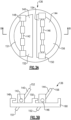
- FIG. 3A shows an embodiment 136 where the shafts 142 and 146 are at an intermediate location.
- the flapper valve portion 140 has one end 151 on one side of the shaft 142 and the opposed end 152 on the other side of the shaft 146.
- the flapper valve portion 144 has an end 154 on one side of the shaft 146 and an opposed end 156 on the other side of the shaft 146.
- valve stops 148 and 150 are shown for stopping rotation of the valve portions 140 and 144 in the closed position.
- a flapper check valve under this disclosure could be said to include a valve seat body.
- Two flapper valve portions are each mounted on their own shaft to the valve seat body, and pivotable between open and closed positions.
- the flapper valve portions pivot in a common rotational direction to the open position and to the closed position.
- a fluid system under this disclosure could be said to include a compressor, a high pressure tap from the compressor section and a low pressure tap.
- the high pressure tap is connected to a selectively closed and opened valve and into a chamber.
- the low pressure tap passes into a low pressure duct, and then to a flapper check valve.
- a control for the control valve is programmed selectively opens and closes the control valve to provide the higher pressure air into the chamber.
- the check valve blocks the lower pressure tap from entering the chamber when the higher pressure air is delivered into the chamber, with the flapper check valve being allowed to open and deliver the lower pressure air into the chamber valve housing when the control valve is closed.
- the flapper check valve has a valve seat body, two flapper valve portions each mounted on their own shaft to the valve seat body, and pivotable between open and closed positions, with the flapper valve portions pivoting in a common rotational direction to the open position and to the closed position.
Landscapes
- Engineering & Computer Science (AREA)
- General Engineering & Computer Science (AREA)
- Mechanical Engineering (AREA)
- Health & Medical Sciences (AREA)
- General Health & Medical Sciences (AREA)
- Pulmonology (AREA)
- Aviation & Aerospace Engineering (AREA)
- Check Valves (AREA)
Abstract
A flapper check valve includes a valve seat body (60). Two flapper valve portions (140, 144) are each mounted on their own shaft (42, 46) to the valve seat body, and pivotable between open and closed positions. The flapper valve portions pivot in a common rotational direction to the open position and to the closed position. A fluid systems is also disclosed.
Description
- This application relates to a flapper check valve wherein the two flapper valve members rotate in a common direction between open and closed positions.
- Check valves are used in any number of applications. One type of check valve is a so called flapper valve.
- In a typical flapper valve there are two valve members each mounted to pivot about a pivot axis.
- As one example system, in many aerospace applications there is a high pressure source delivered to a use and an alternative lower pressure source. The high pressure source passes through a valve which may be electronically commanded closed at higher power operation. When the high pressure source is being delivered to the use it maintains a check valve closed so the low pressure source does not reach the use.
- However, at high power operation the low pressure source will be at a sufficiently high enough pressure that it may be delivered to the use. In such a case the valve on the high pressure source is electronically commanded closed and the low pressure source air can pass through the flapper valve to the use.
- Known flapper valves have two pivoting flapper valve portions which pivot in opposed rotational directions. Such flapper valves may have challenges if turbulent airflow reaches the check valve. Moreover, there may be dithering, or challenges with returning to a closed position.
- A flapper check valve includes a valve seat body. Two flapper valve portions are each mounted on their own shaft to the valve seat body, and move between open and closed positions. The flapper valve portions pivot in a common rotational direction to the open position and to the closed position.
- These and other features will be best understood from the following drawings and specification, the following is a brief description.
-
-
Figure 1A schematically shows an aircraft with an associated system. -
Figure 1B shows a flapper valve from theFigure 1A system in an open position. -
Figure 1C shows a feature of theFigure 1A and 1B flapper valve. -
Figure 2A shows the flapper valve in a closed position. -
Figure 2B also shows the flapper valve in a closed position. -
Figure 3A shows an alternative embodiment flapper valve. -
Figure 3B shows the alternative embodiment flapper valve in an open position. -
Figure 1A schematically shows anaircraft 20 receiving agas turbine engine 22.Gas turbine engine 22 includes acompressor 24. Afirst air tap 26 taps higher pressure air from thecompressor 24 to be selectively delivered to a use 27 on theaircraft 20. The use 27 could be an environmental control system for the aircraft, cooling air for a bearing on thegas turbine engine 22, or any number of other applications. Asecond tap 28 is shown tapped from thecompressor 24 at what will be a lower pressure location in thecompressor 24. - Air from the
higher pressure tap 26 passes through a selectively openedvalve 30 downstream into achamber 32, and then through aduct 38 to the use 27. Acontrol 31 is schematically shown controlling thevalve 30.Control 31 may be an electronic control such a full authority digital electric controller ("FADEC") or could be a dedicated control. - The
low pressure air 28 is delivered into aduct 34. Acheck valve 36 is placed on theduct 34 and blocks the low pressure air from reaching thechamber 32 when higher pressure air is delivered throughvalve 30 into thechamber 32. - However, at high power operation of the
gas turbine engine 22 thelower pressure tap 28 may be at a sufficiently high pressure to meet the needs of the use 27. In such a case, thevalve 30 is closed such that the lower pressure air fromtap 28 can move through thecheck valve 36 into thechamber 32. This improves the efficiency of thegas turbine engine 22 operation. - As shown, the
check valve 36 includes two pivotingflapper valve portions Flapper valve portion 40 pivots on theshaft 42 andflapper valve portion 44 pivots on theshaft 46. - As shown in
Figure 1B , the arrangement is such that theshaft 42 is on an opposed side of theflapper valve portion 40 from theshaft 46 of theflapper valve portion 44.Stops - Thus, it could be said in this arrangement in one direction there is a shaft, a flapper valve portion, a second shaft and then a second flapper valve portion.
- As shown in
Figure 1C , with such an arrangement theflapper valve portions - Returning to
Figure 1A , as can be appreciated, the position of theflap members downstream portion 39 of theduct 38. Avalve seat body 60 mounts the flapper valve portions. - As shown, the air initially entering the
chamber 32 is within aduct portion 37 which extends generally along a first direction X. Theduct section 39 extends along a direction Y. In the disclosed embodiment direction Y is generally perpendicular to direction X, thus defining an effective 90 degree turn. In embodiments direction Y will have at least a component in a direction which is perpendicular to the direction X. As shown by arrows here, the position of theflapper valve portions - This arrangement is more capable of handling turbulent flow than the prior art.
-
Figure 2A is a view of theflapper valve 36 in a closed portion.Flapper valve portions -
Figure 2B shows thevalve 36 in the closed position. As can be appreciated, in this embodiment since theduct 34 is cylindrical the combination of theflapper valve members flapper valve portion 40 has aforward face 54 which is generally straight. The opposedflapper valve portion 44 has anend 52 remote from itsshaft 46 which is part cylindrical. - In the
Figures 1A, 1B ,2A and 2B , theshafts flapper valve portions -
Figure 3A shows anembodiment 136 where theshafts flapper valve portion 140 has oneend 151 on one side of theshaft 142 and theopposed end 152 on the other side of theshaft 146. Similarly, theflapper valve portion 144 has anend 154 on one side of theshaft 146 and anopposed end 156 on the other side of theshaft 146. - Now, as shown in
Figure 3B , when theflapper valve portions ends valve seat body 160 whereas theends valve seat body 160. Valve stops 148 and 150 are shown for stopping rotation of thevalve portions - A flapper check valve under this disclosure could be said to include a valve seat body. Two flapper valve portions are each mounted on their own shaft to the valve seat body, and pivotable between open and closed positions. The flapper valve portions pivot in a common rotational direction to the open position and to the closed position.
- A fluid system under this disclosure could be said to include a compressor, a high pressure tap from the compressor section and a low pressure tap. The high pressure tap is connected to a selectively closed and opened valve and into a chamber. The low pressure tap passes into a low pressure duct, and then to a flapper check valve. A control for the control valve is programmed selectively opens and closes the control valve to provide the higher pressure air into the chamber. The check valve blocks the lower pressure tap from entering the chamber when the higher pressure air is delivered into the chamber, with the flapper check valve being allowed to open and deliver the lower pressure air into the chamber valve housing when the control valve is closed. The flapper check valve has a valve seat body, two flapper valve portions each mounted on their own shaft to the valve seat body, and pivotable between open and closed positions, with the flapper valve portions pivoting in a common rotational direction to the open position and to the closed position.
- Although embodiment have been disclosed, a worker of skill in this art would recognize that certain modifications would come within the scope of this disclosure. For that reason the following claims should be studied to determine the true scope and content of this disclosure.
Claims (13)
- A flapper check valve comprising:a valve seat body (60);two flapper valve portions (140, 144) each mounted on their own shaft (42, 46) to the valve seat body, and pivotable between open and closed positions, with said flapper valve portions pivoting in a common rotational direction to the open position and to the closed position.
- The flapper check valve as set forth in claim 1, wherein the shaft for one of the flapper valve portions is on an opposed side of the one of the flapper valve portion relative to the shaft of the other of the flapper valve portions, and the other of the flapper valve portions is on an opposed side of its shaft relative to the first of the flapper valve portions.
- The flapper check valve as set forth in claim 2, wherein stops (48, 50) are provided to limit the movement of the first and second flapper valve portions.
- The flapper check valve as set forth in claim 3, wherein the shafts of the first and second flapper valve portions are at ends of the flapper valve portions.
- The flapper check valve as set forth in claim 3, wherein the shafts of the flapper valve portions are at an intermediate location in each of the flapper valve portions such that when in the open position, one end of each of the flapper valve portions is above the valve seat body and an opposed end of each of the flapper valve portions has pivoted in the common direction to be below the valve seat body.
- The flapper check valve as set forth in any preceding claim, wherein a forward face (54) at a first of the flapper valve portion facing a second of the flapper valve portions is straight and a forward face (52) of the second of the flapper valve portions facing away from the first of the flapper valve portion is cylindrical.
- The flapper check valve as set forth in any preceding claim, wherein the shafts of the first and second flapper valve portions are at ends of the flapper valve portions.
- The flapper check valve as set forth in any preceding claim, wherein the shafts of the flapper valve portions are at an intermediate location in each of the flapper valve portions such that when in the open position, one end of each of the flapper valve portions is above the valve seat body and an opposed end of each of the flapper valve portions has pivoted in the common direction to be below the valve seat body.
- A fluid system comprising:a compressor (24), a high pressure tap (26) from the compressor section and a low pressure tap (28), the high pressure tap connected to a selectively closed and opened valve and into a chamber (32);the low pressure tap passing into a low pressure duct (34), and then to a flapper check valve (36) as claimed in any preceding claim, with a control for the control valve programmed to selectively opens and closes the control valve to provide the higher pressure air into the chamber, and the flapper check valve blocking the lower pressure tap from entering the chamber when the higher pressure air is delivered into the chamber, with the flapper check valve being allowed to open and deliver the lower pressure air into the chamber valve housing when the control valve is closed.
- The fluid system as set forth in claim 9, wherein the chamber (32) is connected to deliver compressed air to a use.
- The fluid system as set forth in claim 10, wherein the use is on an aircraft.
- The fluid system as set forth in claim 10 or 11, wherein the low pressure duct delivering air to the flapper check valve extends along a first direction, and air entering the chamber and passing downstream toward the use moving through a duct portion extending along a second direction having at least a component perpendicular to the first direction, and the flapper valve portions in the open position guiding air from the first direction and to the second direction.
- The fluid system as set forth in claim 12, wherein the second direction is perpendicular to the first direction.
Applications Claiming Priority (1)
| Application Number | Priority Date | Filing Date | Title |
|---|---|---|---|
| US18/345,582 US12264668B2 (en) | 2023-06-30 | 2023-06-30 | Flapper valve with common rotational direction |
Publications (1)
| Publication Number | Publication Date |
|---|---|
| EP4484809A1 true EP4484809A1 (en) | 2025-01-01 |
Family
ID=91759396
Family Applications (1)
| Application Number | Title | Priority Date | Filing Date |
|---|---|---|---|
| EP24185721.8A Pending EP4484809A1 (en) | 2023-06-30 | 2024-07-01 | Flapper valve with common rotational direction |
Country Status (2)
| Country | Link |
|---|---|
| US (1) | US12264668B2 (en) |
| EP (1) | EP4484809A1 (en) |
Citations (7)
| Publication number | Priority date | Publication date | Assignee | Title |
|---|---|---|---|---|
| US3933173A (en) * | 1968-02-26 | 1976-01-20 | Yoshio Kajita | Check valve |
| US6273136B1 (en) * | 1998-03-25 | 2001-08-14 | Nord-Micro Elektronik Feinmechanik | Differential valve, specifically a cabin air discharge valve in an aircraft, and method for regulating cabin pressure |
| EP2669443A1 (en) * | 2012-05-31 | 2013-12-04 | Holding Dinnissen B.V. | Pressure relief device |
| US20170363003A1 (en) * | 2016-06-17 | 2017-12-21 | United Technologies Corporation | Gas turbine engine and method to cool a gas turbine engine case assembly |
| CN112096884A (en) * | 2020-09-17 | 2020-12-18 | 扬州海通电子科技有限公司 | A mechanical one-way ventilation valve |
| CN113483127A (en) * | 2021-07-02 | 2021-10-08 | 江苏瑞雨斯环保科技有限公司 | Composite material special-shaped air pipe check valve for circular gas transmission pipeline |
| CN114151585A (en) * | 2021-12-27 | 2022-03-08 | 凯龙高科技股份有限公司 | One-way switch valve device |
Family Cites Families (14)
| Publication number | Priority date | Publication date | Assignee | Title |
|---|---|---|---|---|
| DE1806409A1 (en) * | 1968-02-26 | 1969-09-04 | Yoshio Kajita | Check valve |
| DE2715345C2 (en) * | 1977-04-06 | 1982-04-29 | Klein, Schanzlin & Becker Ag, 6710 Frankenthal | Device for preventing flap blows |
| KR200171953Y1 (en) * | 1999-05-06 | 2000-03-15 | 박일열 | Large size non-slam check valve |
| US6796327B2 (en) | 2001-11-09 | 2004-09-28 | Bnl Industries, Inc. | Check valve with multiple doors |
| US20080078459A1 (en) | 2006-09-29 | 2008-04-03 | Honeywell International, Inc. | Rotary hydraulic damper for check valve |
| JP5439267B2 (en) * | 2010-04-26 | 2014-03-12 | 株式会社日立製作所 | Wind pressure shutter and cooling fan system |
| CN104405935A (en) * | 2014-11-21 | 2015-03-11 | 苏州福润机械有限公司 | Non-return valve of flue |
| EP3193059B1 (en) | 2016-01-15 | 2019-05-22 | Hamilton Sundstrand Corporation | Check valve |
| EP3193055B1 (en) | 2016-01-15 | 2020-05-06 | Hamilton Sundstrand Corporation | Check valve |
| EP3258146B1 (en) | 2016-06-14 | 2020-04-08 | Hamilton Sundstrand Corporation | Check valve |
| CN206496046U (en) | 2017-03-06 | 2017-09-15 | 西安飞豹科技有限公司 | A kind of check valve of error-preventive design |
| US10683812B2 (en) | 2018-08-17 | 2020-06-16 | Raytheon Technologies Corporation | Dual valve system with mechanical linkage |
| EP3667138B1 (en) | 2018-12-10 | 2022-11-23 | Hamilton Sundstrand Corporation | Check valve |
| CN113531175A (en) * | 2021-08-13 | 2021-10-22 | 深圳中雅机电实业有限公司 | Rainproof check valve of silencer |
-
2023
- 2023-06-30 US US18/345,582 patent/US12264668B2/en active Active
-
2024
- 2024-07-01 EP EP24185721.8A patent/EP4484809A1/en active Pending
Patent Citations (7)
| Publication number | Priority date | Publication date | Assignee | Title |
|---|---|---|---|---|
| US3933173A (en) * | 1968-02-26 | 1976-01-20 | Yoshio Kajita | Check valve |
| US6273136B1 (en) * | 1998-03-25 | 2001-08-14 | Nord-Micro Elektronik Feinmechanik | Differential valve, specifically a cabin air discharge valve in an aircraft, and method for regulating cabin pressure |
| EP2669443A1 (en) * | 2012-05-31 | 2013-12-04 | Holding Dinnissen B.V. | Pressure relief device |
| US20170363003A1 (en) * | 2016-06-17 | 2017-12-21 | United Technologies Corporation | Gas turbine engine and method to cool a gas turbine engine case assembly |
| CN112096884A (en) * | 2020-09-17 | 2020-12-18 | 扬州海通电子科技有限公司 | A mechanical one-way ventilation valve |
| CN113483127A (en) * | 2021-07-02 | 2021-10-08 | 江苏瑞雨斯环保科技有限公司 | Composite material special-shaped air pipe check valve for circular gas transmission pipeline |
| CN114151585A (en) * | 2021-12-27 | 2022-03-08 | 凯龙高科技股份有限公司 | One-way switch valve device |
Also Published As
| Publication number | Publication date |
|---|---|
| US20250003403A1 (en) | 2025-01-02 |
| US12264668B2 (en) | 2025-04-01 |
Similar Documents
| Publication | Publication Date | Title |
|---|---|---|
| US5771929A (en) | Low noise ball valve assembly with airfoil insert | |
| US8356486B2 (en) | APU bleed valve with integral anti-surge port | |
| EP0831262A2 (en) | Ball valve assembly | |
| JP3837166B2 (en) | Integrated bypass valve and air circulation machine | |
| EP3018323A1 (en) | Bleed valve | |
| EP1918560B1 (en) | Combined control for supplying cooling air and support air in a turbine engine nozzle | |
| CN104220730B (en) | Butterfly bypass valve, and throttle loss recovery system incorporating same | |
| JP7207216B2 (en) | fuel cell system | |
| EP3988772B1 (en) | Pressure regulating valve assembly | |
| EP1988315A2 (en) | Fast acting aircraft engine bleed air check valve | |
| EP3118436B1 (en) | Bleed valves for gas turbine engines | |
| EP3135964B1 (en) | Flow diverting flapper | |
| US20130118624A1 (en) | Sealed flapper diverter valve | |
| EP1728992B1 (en) | Bleed valve for a gas turbine engine and a corresponding gas turbine. | |
| CN102171416B (en) | System for controlling variable geometry equipment of a gas turbine engine especially comprising a guiding track connection | |
| US12264668B2 (en) | Flapper valve with common rotational direction | |
| US20170341763A1 (en) | None | |
| US10648359B2 (en) | System for controlling variable-setting blades for a turbine engine | |
| US10844778B2 (en) | Exhaust-flow-rate control valve, and two-stage supercharging system provided with same | |
| EP3647601A1 (en) | Adjustment mechanism for an inlet flow section of a compressor wheel of a turbocharger | |
| EP4155505A1 (en) | Spring loaded sleeve valve with controlled closing force | |
| EP3440333B1 (en) | Exhaust gas valve device | |
| EP2233804A1 (en) | Butterfly valve combined with check valve | |
| EP3842627B1 (en) | Air turbine starter air valve | |
| US20230341058A1 (en) | Energy Recovery Valve System with Spherical Segment Valve for Controlling the Fluid Flow in a Duct |
Legal Events
| Date | Code | Title | Description |
|---|---|---|---|
| PUAI | Public reference made under article 153(3) epc to a published international application that has entered the european phase |
Free format text: ORIGINAL CODE: 0009012 |
|
| STAA | Information on the status of an ep patent application or granted ep patent |
Free format text: STATUS: THE APPLICATION HAS BEEN PUBLISHED |
|
| AK | Designated contracting states |
Kind code of ref document: A1 Designated state(s): AL AT BE BG CH CY CZ DE DK EE ES FI FR GB GR HR HU IE IS IT LI LT LU LV MC ME MK MT NL NO PL PT RO RS SE SI SK SM TR |
|
| STAA | Information on the status of an ep patent application or granted ep patent |
Free format text: STATUS: REQUEST FOR EXAMINATION WAS MADE |
|
| 17P | Request for examination filed |
Effective date: 20250701 |