EP4484780A1 - Bearing retention system - Google Patents
Bearing retention system Download PDFInfo
- Publication number
- EP4484780A1 EP4484780A1 EP24182601.5A EP24182601A EP4484780A1 EP 4484780 A1 EP4484780 A1 EP 4484780A1 EP 24182601 A EP24182601 A EP 24182601A EP 4484780 A1 EP4484780 A1 EP 4484780A1
- Authority
- EP
- European Patent Office
- Prior art keywords
- shaft
- bearing
- ring
- recess
- housing
- Prior art date
- Legal status (The legal status is an assumption and is not a legal conclusion. Google has not performed a legal analysis and makes no representation as to the accuracy of the status listed.)
- Pending
Links
Images


Classifications
-
- F—MECHANICAL ENGINEERING; LIGHTING; HEATING; WEAPONS; BLASTING
- F16—ENGINEERING ELEMENTS AND UNITS; GENERAL MEASURES FOR PRODUCING AND MAINTAINING EFFECTIVE FUNCTIONING OF MACHINES OR INSTALLATIONS; THERMAL INSULATION IN GENERAL
- F16H—GEARING
- F16H57/00—General details of gearing
- F16H57/02—Gearboxes; Mounting gearing therein
- F16H57/021—Shaft support structures, e.g. partition walls, bearing eyes, casing walls or covers with bearings
-
- B—PERFORMING OPERATIONS; TRANSPORTING
- B64—AIRCRAFT; AVIATION; COSMONAUTICS
- B64C—AEROPLANES; HELICOPTERS
- B64C27/00—Rotorcraft; Rotors peculiar thereto
- B64C27/04—Helicopters
- B64C27/12—Rotor drives
-
- F—MECHANICAL ENGINEERING; LIGHTING; HEATING; WEAPONS; BLASTING
- F16—ENGINEERING ELEMENTS AND UNITS; GENERAL MEASURES FOR PRODUCING AND MAINTAINING EFFECTIVE FUNCTIONING OF MACHINES OR INSTALLATIONS; THERMAL INSULATION IN GENERAL
- F16C—SHAFTS; FLEXIBLE SHAFTS; ELEMENTS OR CRANKSHAFT MECHANISMS; ROTARY BODIES OTHER THAN GEARING ELEMENTS; BEARINGS
- F16C35/00—Rigid support of bearing units; Housings, e.g. caps, covers
- F16C35/04—Rigid support of bearing units; Housings, e.g. caps, covers in the case of ball or roller bearings
- F16C35/06—Mounting or dismounting of ball or roller bearings; Fixing them onto shaft or in housing
- F16C35/063—Fixing them on the shaft
-
- F—MECHANICAL ENGINEERING; LIGHTING; HEATING; WEAPONS; BLASTING
- F16—ENGINEERING ELEMENTS AND UNITS; GENERAL MEASURES FOR PRODUCING AND MAINTAINING EFFECTIVE FUNCTIONING OF MACHINES OR INSTALLATIONS; THERMAL INSULATION IN GENERAL
- F16C—SHAFTS; FLEXIBLE SHAFTS; ELEMENTS OR CRANKSHAFT MECHANISMS; ROTARY BODIES OTHER THAN GEARING ELEMENTS; BEARINGS
- F16C19/00—Bearings with rolling contact, for exclusively rotary movement
- F16C19/22—Bearings with rolling contact, for exclusively rotary movement with bearing rollers essentially of the same size in one or more circular rows, e.g. needle bearings
- F16C19/34—Bearings with rolling contact, for exclusively rotary movement with bearing rollers essentially of the same size in one or more circular rows, e.g. needle bearings for both radial and axial load
- F16C19/36—Bearings with rolling contact, for exclusively rotary movement with bearing rollers essentially of the same size in one or more circular rows, e.g. needle bearings for both radial and axial load with a single row of rollers
- F16C19/364—Bearings with rolling contact, for exclusively rotary movement with bearing rollers essentially of the same size in one or more circular rows, e.g. needle bearings for both radial and axial load with a single row of rollers with tapered rollers, i.e. rollers having essentially the shape of a truncated cone
-
- F—MECHANICAL ENGINEERING; LIGHTING; HEATING; WEAPONS; BLASTING
- F16—ENGINEERING ELEMENTS AND UNITS; GENERAL MEASURES FOR PRODUCING AND MAINTAINING EFFECTIVE FUNCTIONING OF MACHINES OR INSTALLATIONS; THERMAL INSULATION IN GENERAL
- F16C—SHAFTS; FLEXIBLE SHAFTS; ELEMENTS OR CRANKSHAFT MECHANISMS; ROTARY BODIES OTHER THAN GEARING ELEMENTS; BEARINGS
- F16C2226/00—Joining parts; Fastening; Assembling or mounting parts
- F16C2226/50—Positive connections
- F16C2226/70—Positive connections with complementary interlocking parts
-
- F—MECHANICAL ENGINEERING; LIGHTING; HEATING; WEAPONS; BLASTING
- F16—ENGINEERING ELEMENTS AND UNITS; GENERAL MEASURES FOR PRODUCING AND MAINTAINING EFFECTIVE FUNCTIONING OF MACHINES OR INSTALLATIONS; THERMAL INSULATION IN GENERAL
- F16C—SHAFTS; FLEXIBLE SHAFTS; ELEMENTS OR CRANKSHAFT MECHANISMS; ROTARY BODIES OTHER THAN GEARING ELEMENTS; BEARINGS
- F16C2226/00—Joining parts; Fastening; Assembling or mounting parts
- F16C2226/50—Positive connections
- F16C2226/80—Positive connections with splines, serrations or similar profiles to prevent movement between joined parts
-
- F—MECHANICAL ENGINEERING; LIGHTING; HEATING; WEAPONS; BLASTING
- F16—ENGINEERING ELEMENTS AND UNITS; GENERAL MEASURES FOR PRODUCING AND MAINTAINING EFFECTIVE FUNCTIONING OF MACHINES OR INSTALLATIONS; THERMAL INSULATION IN GENERAL
- F16C—SHAFTS; FLEXIBLE SHAFTS; ELEMENTS OR CRANKSHAFT MECHANISMS; ROTARY BODIES OTHER THAN GEARING ELEMENTS; BEARINGS
- F16C2326/00—Articles relating to transporting
- F16C2326/43—Aeroplanes; Helicopters
-
- F—MECHANICAL ENGINEERING; LIGHTING; HEATING; WEAPONS; BLASTING
- F16—ENGINEERING ELEMENTS AND UNITS; GENERAL MEASURES FOR PRODUCING AND MAINTAINING EFFECTIVE FUNCTIONING OF MACHINES OR INSTALLATIONS; THERMAL INSULATION IN GENERAL
- F16C—SHAFTS; FLEXIBLE SHAFTS; ELEMENTS OR CRANKSHAFT MECHANISMS; ROTARY BODIES OTHER THAN GEARING ELEMENTS; BEARINGS
- F16C2361/00—Apparatus or articles in engineering in general
- F16C2361/65—Gear shifting, change speed gear, gear box
-
- F—MECHANICAL ENGINEERING; LIGHTING; HEATING; WEAPONS; BLASTING
- F16—ENGINEERING ELEMENTS AND UNITS; GENERAL MEASURES FOR PRODUCING AND MAINTAINING EFFECTIVE FUNCTIONING OF MACHINES OR INSTALLATIONS; THERMAL INSULATION IN GENERAL
- F16H—GEARING
- F16H57/00—General details of gearing
- F16H57/02—Gearboxes; Mounting gearing therein
- F16H2057/02039—Gearboxes for particular applications
- F16H2057/02043—Gearboxes for particular applications for vehicle transmissions
Definitions
- a VTOL may include one or more rotors coupled to a main rotor shaft.
- the main rotor shaft is driven to rotate and is supported for rotation within a gearbox of the aircraft by one or more bearings.
- Embodiments described herein provide a gear box including a housing, a shaft that is driven by the gear, the shaft including a recess, a bearing mounted between the shaft and the housing to support the shaft for rotation with respect to the housing about a rotation axis, and a ring assembly for axially securing the bearing to the shaft.
- the ring assembly surrounds the shaft and is seated in the recess.
- the recess has a retaining surface including a conical surface extending at an angle to the rotation axis, a curved surface, and a transition surface extending between the conical surface and the curved surface, the transition surface extending generally parallel to the rotation axis.
- Embodiments described herein provide a bearing retention system for a gear box.
- the gear box includes a housing and a shaft at least partially positioned within the housing.
- the system includes a bearing mounted between the shaft and the housing to support the shaft for rotation relative to the housing about a rotation axis.
- the bearing is adjacent a shoulder formed in the shaft.
- the bearing includes an inner race surrounding the shaft, an outer race coupled to the housing, and a plurality of rollers positioned between the inner race and the outer race to allow rotation of the outer race with respect to the inner race.
- a split ring surrounds the shaft and is selectively engageable within a recess formed in the shaft.
- the recess and the shoulder are on axially opposite sides of the bearing.
- a locking ring surrounds the split ring and biases the split ring into the recess.
- the bearing is axially secured with respect to the shaft between the shoulder and the recess.
- Embodiments described herein provide an aircraft includes a main body extending between a nose and a tail, a shaft extending between a first end and a second end along an axis, a rotor assembly mounted on the first end of the shaft, and a gear box configured to drive the shaft to rotate the rotor assembly, the gear box including a housing.
- a bearing is mounted between the shaft and the housing to support the shaft for rotation with respect to the housing about the axis.
- the shaft includes a shoulder and a recess and the bearing rests against the shoulder.
- a ring assembly for axially securing the bearing to the shaft includes a split ring at least partially seated within the recess, and a locking ring surrounding the split ring to bias the split ring into the recess.
- FIG. 1 illustrates a vertical take-off and landing (VTOL) aircraft 10 or rotary wing aircraft according to some embodiments.
- the aircraft 10 includes a main body 14 including an airframe 18 and an empennage 22.
- the airframe 18 extends between a nose 30 and a tail 34.
- the aircraft 10 includes a rotor assembly 38 coupled to the main body 14 between the nose 30 and the tail 34.
- the aircraft 10 is an single rotor helicopter and includes a main rotor assembly 38 that rotates about a rotational axis R.
- the main rotor assembly 38 is mounted on a main shaft 58 (also referred to herein as a shaft or a main rotor shaft) extending along a shaft axis S between a first end 62 and a second end 66.
- the main rotor assembly 38 includes a plurality of blades 70 coupled to a hub 74.
- the hub 74 is coupled to the first end 62 of the shaft 58.
- the second end 66 of the shaft 58 is positioned within the airframe 18. Rotation of the shaft 58 rotates the blades 70 about the rotational axis R generating lift.
- the shaft 58 may be rotated by a gear train 78 positioned within the gear box 54.
- the first bearing 94 is also press-fit onto the support portion 118 of the shaft 58 such that a bottom edge 154 of the inner race 122 abuts the second bearing 98.
- the outer race 126 of the first bearing 94 is positioned such that an upper edge 158 of the outer race 126 contacts one of the ledges 106 formed in the housing 86.
- the ledge 106 may prevent the bearing assembly 90 from axially displacing in a second direction (i.e., upward or away from the gear box 54) along the shaft axis S relative to the housing 86.
- the spacer sleeve 102 is also be press-fit onto the shaft 58 adjacent the inner race 122 of the first bearing 94.
- the bearing assembly 90 extends along the entire support portion 118 of the shaft 58.
- a ring assembly 170 is coupled to the shaft 58 above the support portion 118 to selectively engage with the recess 114.
- FIG. 3 illustrates an exploded view of the bearing retention system 80 including the ring assembly 170, the bearing assembly 90 (represented schematically by block 90'), and the portion 82 of the shaft 58.
- the ring assembly 170 includes a split ring 174 and an outer ring 178 (also referred to herein as locking ring).
- the split ring 174 is formed of two halves 174a, 174b separated by two splits.
- the split ring 174 may be a unitary piece with a singular split.
- the split ring 174 may be formed of more than two pieces with the corresponding number of splits. The split(s) allows the split ring 174 to bias inwardly to engage the recess 114.
- the split ring 174 includes an inner surface 186 with a profile that is inverse to a profile of the recess 114 (discussed in further detail below).
- the split ring 174 also includes an outer surface 190 having receiving area 194 and a lip 198.
- the lip 198 is slanted with respect to the shaft axis S.
- the recess 114 on the shaft 58 is shown in more detail.
- the recess 114 extends along the shaft axis S to a height H and includes a retaining surface 202.
- the shaft 58 has a first outer diameter measured on the support portion 118.
- the second outer diameter of the upper portion 206 is the same as the first outer diameter of the support portion 118.
- the second outer diameter of the upper portion 206 is smaller than the first outer diameter of the support portion 118.
- the recess 114 extends from the outer diameter to a depth d.
- the depth may be between .115 inches and .145 inches, and more specifically may be 0.13 inches. In other applications, the depth may vary based on the size of the loads applied to the shaft 58, the material and fracture properties of the shaft, and other factors. Thus, any dimensions given in reference to the exemplary application are not intended to limit the possible applications.
- the shaft 58 is hollow and therefore has a thickness t1 at the support portion 118 and a thickness t2 at the upper portion 206.
- the thickness t1 is equal to the thickness t2, however, in some embodiments the thickness t2 may be different than the thickness t1.
- the "thickness" may refer to a measurement from the central axis to the outer surface (i.e., the radius).
- the diameter of the upper portion 206 is equal to or less than the diameter of the support portion 118, so the bearing assembly 90 may be moved down over the upper portion 206 and be press fit onto the support portion 118 against the shoulder 110.
- the recess 114 is set in from the outer diameter of the support portion 118 so that the bearing retention system 80 does not interfere with installation of the bearing assembly 90.
- the retaining surface 202 includes a conical surface 210, a transition surface 214, and a curved surface 218.
- the conical surface 210 is positioned adjacent the upper portion 206 of the shaft 58 and extends from the outer diameter to the depth d.
- the conical surface 210 extends on a straight line at an angle ⁇ .
- the angle ⁇ is a relatively shallow acute angle measured relative to the shaft axis S.
- the conical surface 210 extends along the shaft axis S to a first height h1.
- the conical surface 210 is angled with respect to the shaft axis to form a stop capable of reacting axial forces to prevent axial movement upward along the shaft 58.
- the first height h1 should be sufficiently long so that axial force applied to the conical surface 210 creates a stress profile within the shaft 58 that is within the acceptable range allowed by the material.
- the transition surface 214 of the retaining surface 202 extends generally parallel to the shaft axis S.
- the transition surface 214 extends to a second height h2 along the shaft axis S.
- the shaft 58 has a thickness t3 at the transition surface 214.
- the thickness t3 of the shaft 58 in the recess 114 is less than the thicknesses t1, t2, and is generally equal to the thickness t2 minus the depth d.
- the transition surface 214 is recessed from the outer diameter by the depth d.
- the angle ⁇ may be between about 10 degrees and 20 degrees relative to the shaft axis S. More specifically, the angle ⁇ may be about 14.6 degrees.
- the first height h1 may be between 0.12 inches and 0.92 inches. Specifically, the first height h1 may be approximately 0.52 inches.
- the second height h2 may be between .15 inches and 0.35 inches. The second height h2 may be 0.25 inches.
- the shaft 58 is subject to high loading, including bending loads and negative thrust loads.
- Other bearing retainment systems that use a ring assembly may include a groove with a profile having abrupt changes in thickness as you travel along the shaft axis S. These profiles can cause points with high stress concentration which leads to cracking and failure when the shaft is fatigue loaded.
- the profile of the recess 114 allows for engagement with the ring assembly 170 to axially secure the bearing assembly 90 without decreasing the fatigue life of the shaft 58. Specifically, increasing the radius r1 of the curved surface 218 decreases the impact of the recess 114 on the fatigue life of the shaft 58.
- Other bearing retainment systems may use threads to locate a nut to act as an axial stop.
Landscapes
- Engineering & Computer Science (AREA)
- General Engineering & Computer Science (AREA)
- Mechanical Engineering (AREA)
- Aviation & Aerospace Engineering (AREA)
- Mounting Of Bearings Or Others (AREA)
Abstract
A gear box includes a housing, a shaft that is driven by the gear, the shaft including a recess, a bearing mounted between the shaft and the housing to support the shaft for rotation with respect to the housing about a rotation axis, and a ring assembly for axially securing the bearing to the shaft. The ring assembly surrounds the shaft and is seated in the recess. The recess has a retaining surface including a conical surface extending at an angle to the rotation axis, a curved surface, and a transition surface extending between the conical surface and the curved surface, the transition surface extending generally parallel to the rotation axis.
Description
- Embodiments described herein relate to shaft bearings, and in particular shaft bearings positioned on shafts subject to high loads.
- Aircrafts, and specifically vertical take-off and landing (VTOL) aircrafts utilize rotors to provide lift and thrust. A VTOL may include one or more rotors coupled to a main rotor shaft. The main rotor shaft is driven to rotate and is supported for rotation within a gearbox of the aircraft by one or more bearings.
- Embodiments described herein provide a gear box including a housing, a shaft that is driven by the gear, the shaft including a recess, a bearing mounted between the shaft and the housing to support the shaft for rotation with respect to the housing about a rotation axis, and a ring assembly for axially securing the bearing to the shaft. The ring assembly surrounds the shaft and is seated in the recess. The recess has a retaining surface including a conical surface extending at an angle to the rotation axis, a curved surface, and a transition surface extending between the conical surface and the curved surface, the transition surface extending generally parallel to the rotation axis.
- Embodiments described herein provide a bearing retention system for a gear box. The gear box includes a housing and a shaft at least partially positioned within the housing. The system includes a bearing mounted between the shaft and the housing to support the shaft for rotation relative to the housing about a rotation axis. The bearing is adjacent a shoulder formed in the shaft. The bearing includes an inner race surrounding the shaft, an outer race coupled to the housing, and a plurality of rollers positioned between the inner race and the outer race to allow rotation of the outer race with respect to the inner race. A split ring surrounds the shaft and is selectively engageable within a recess formed in the shaft. The recess and the shoulder are on axially opposite sides of the bearing. A locking ring surrounds the split ring and biases the split ring into the recess. The bearing is axially secured with respect to the shaft between the shoulder and the recess.
- Embodiments described herein provide an aircraft includes a main body extending between a nose and a tail, a shaft extending between a first end and a second end along an axis, a rotor assembly mounted on the first end of the shaft, and a gear box configured to drive the shaft to rotate the rotor assembly, the gear box including a housing. A bearing is mounted between the shaft and the housing to support the shaft for rotation with respect to the housing about the axis. The shaft includes a shoulder and a recess and the bearing rests against the shoulder. A ring assembly for axially securing the bearing to the shaft includes a split ring at least partially seated within the recess, and a locking ring surrounding the split ring to bias the split ring into the recess.
- Other aspects will become apparent by consideration of the detailed description and accompanying drawings.
-
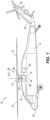
FIG. 1 illustrates an aircraft according to an exemplary embodiment. -
FIG. 2 is a sectional view of one embodiment of a bearing retention system used in a gear box of the aircraft ofFIG. 1 . -
FIG. 3 is an exploded view of the bearing retention system ofFIG. 2 . -
FIG. 4 is a detail view of a recess positioned on a main rotor shaft of the aircraft ofFIG. 1 . - Before any embodiments are explained in detail, it is to be understood that the embodiments described herein are provided as examples and the details of construction and the arrangement of the components described herein or illustrated in the accompanying drawings should not be considered limiting. Also, it is to be understood that the phraseology and terminology used herein is for the purpose of description and should not be regarded as limited. The use of "including," "comprising" or "having" and variations thereof herein is meant to encompass the items listed thereafter and equivalents thereof as well as additional items. The terms "mounted," "connected" and "coupled" are used broadly and encompass both direct and indirect mounting, connecting, and coupling. Further, "connected" and "coupled" are not restricted to physical or mechanical connections or couplings, and may include electrical connections or couplings, whether direct or indirect. Also, electronic communications and notifications may be performed using any known means including direct connections, wireless connections, and the like.
-
FIG. 1 illustrates a vertical take-off and landing (VTOL)aircraft 10 or rotary wing aircraft according to some embodiments. Theaircraft 10 includes amain body 14 including anairframe 18 and anempennage 22. Theairframe 18 extends between anose 30 and atail 34. Theaircraft 10 includes arotor assembly 38 coupled to themain body 14 between thenose 30 and thetail 34. In the illustrated embodiment, theaircraft 10 is an single rotor helicopter and includes amain rotor assembly 38 that rotates about a rotational axis R. In other embodiments, the aircraft may be of a different type, for example, dual rotor assembly helicopters, tandem rotor helicopters including offset rotor assemblies, tandem intermeshing rotor helicopters including overlapping rotor assemblies, coaxial helicopters including a plurality of rotary wings aligned along a common axis, and the like, and therotor assembly 38 may be the rotor assembly of the respective aircraft. Themain body 14 defines a cockpit in theairframe 18 having one or more seats for flight crew and optional passengers. Themain rotor assembly 38 is driven by apower source 50, such as, for example, one or more motors via a mainrotor gear box 54. The one or more motors can include an electric motor, a piston engine, a gas turbine, or other device for providing motion. - The
main rotor assembly 38 is mounted on a main shaft 58 (also referred to herein as a shaft or a main rotor shaft) extending along a shaft axis S between afirst end 62 and asecond end 66. When assembled, the shaft axis S is coaxial with the rotational axis R. Themain rotor assembly 38 includes a plurality ofblades 70 coupled to ahub 74. Thehub 74 is coupled to thefirst end 62 of theshaft 58. Thesecond end 66 of theshaft 58 is positioned within theairframe 18. Rotation of theshaft 58 rotates theblades 70 about the rotational axis R generating lift. Theshaft 58 may be rotated by agear train 78 positioned within thegear box 54. - In some operational conditions, wind or extreme flight conditions may create a bending moment or a negative thrust condition within the
main shaft 58. For example, negative thrust may occur in conditions when the aircraft is in a state of autorotation, when the aircraft performs a pushover maneuver, when the aircraft is grounded in high wind conditions, or when the aircraft is grounded and the droop stops are pounded or otherwise impacted. If during these conditions, theshaft 58 is supported via components press-fit onto theshaft 58, the bending moment or negative thrust condition may cause theshaft 58 to axially displace relative to the press-fit components (e.g., bearings). This displacement may be known as "self-disassembly" of a press-fit or interference fit connection. Axial displacement of theshaft 58 may cause additional wear or damage to surrounding components. For example, in some cases theshaft 58 may displace inwardly along the rotational axis R toward the bottom of theaircraft 10, and thesecond end 66 of theshaft 58 may contact and/or interfere with other components adjacent thesecond end 66 of theshaft 58, such as thegear train 78 or an oil sump. - With reference to
FIG. 2 , to prevent axial displacement of themain shaft 58, abearing retention system 80 is used. While thebearing retention system 80 is described in use in the main shaft assembly of theaircraft 10, thebearing retention system 80 may also be usable in other parts of the airplane, for example the tail rotor shaft. Thebearing retention system 80 is also widely applicable in other situations having a rotating shaft subject to high loads, for example, propellers for planes or boats, drills in oil rigs, or wind turbines. -
FIG. 2 illustrates aportion 82 of theshaft 58 within theairframe 18. Theportion 82 of theshaft 58 may extend within ahousing 86 of the mainrotor gear box 54. In the following description, thehousing 86 is described as part of the mainrotor gear box 54, however, in other embodiments thehousing 86 may be a separate housing within theairframe 18 that may be specific to a support assembly or may contain other components. - A
bearing assembly 90 is positioned around theshaft 58 to support theshaft 58 within thehousing 86. In the illustrated embodiment, thebearing 90 includes a first bearing 94, a second bearing 98, and aspacer sleeve 102. In other embodiments, thespacer sleeve 102 may be omitted, thebearing assembly 90 may include a single bearing, or thebearing assembly 90 may have an entirely different configuration of bearings and spacers. Thehousing 86 includes one ormore ledges 106 that support thebearing assembly 90 to prevent axial displacement of thebearing assembly 90 with respect to thehousing 86. - The
portion 82 of theshaft 58 within thehousing 86 includes ashoulder 110 and arecess 114. Theshoulder 110 andrecess 114 are axially spaced along the shaft axis S. Theshaft 58 defines asupport portion 118 formed between theshoulder 110 and therecess 114. The bearingassembly 90 is positioned around theshaft 58 adjacent thesupport portion 118. When assembled, therecess 114 and theshoulder 110 are on opposite ends of the bearingassembly 90. - Specifically, in the illustrated embodiment the
first bearing 94 includes aninner race 122, anouter race 126, and a plurality ofrollers 130 positioned between theinner race 122 andouter race 126 to allow rotation therebetween. Thesecond bearing 98 similarly includes aninner race 134, anouter race 138, and a plurality ofrollers 142 positioned between the tworaces - In the illustrated embodiment, the
second bearing 98 is press-fit onto thesupport portion 118 of theshaft 58 and is positioned such that abottom edge 146 of theinner race 134 abuts or rests on theshoulder 110 formed in theshaft 58. Abottom edge 150 of theouter race 138 is positioned adjacent one of theledges 106 formed in thehousing 86 so that thesecond bearing 98 is supported with respect to thehousing 86. Theouter race 138 may include multiple components, including spacers, and may be axially offset from the inner race to best support theshaft 58 relative to thehousing 86. Theledge 106 prevents the bearingassembly 90 from axially displacing in a first direction (i.e., downward or toward the gear box 54) along the shaft axis S relative to thehousing 86 and theshoulder 110 prevents the bearingassembly 90 from axially displacing in the first direction along the shaft axis S relative to theshaft 58. - The
first bearing 94 is also press-fit onto thesupport portion 118 of theshaft 58 such that abottom edge 154 of theinner race 122 abuts thesecond bearing 98. Theouter race 126 of thefirst bearing 94 is positioned such that anupper edge 158 of theouter race 126 contacts one of theledges 106 formed in thehousing 86. Theledge 106 may prevent the bearingassembly 90 from axially displacing in a second direction (i.e., upward or away from the gear box 54) along the shaft axis S relative to thehousing 86. Thespacer sleeve 102 is also be press-fit onto theshaft 58 adjacent theinner race 122 of thefirst bearing 94. In the illustrated embodiment, the bearingassembly 90 extends along theentire support portion 118 of theshaft 58. Aring assembly 170 is coupled to theshaft 58 above thesupport portion 118 to selectively engage with therecess 114. -
FIG. 3 illustrates an exploded view of thebearing retention system 80 including thering assembly 170, the bearing assembly 90 (represented schematically by block 90'), and theportion 82 of theshaft 58. Thering assembly 170 includes asplit ring 174 and an outer ring 178 (also referred to herein as locking ring). In the illustrated embodiment, thesplit ring 174 is formed of twohalves split ring 174 may be a unitary piece with a singular split. In still other embodiments, thesplit ring 174 may be formed of more than two pieces with the corresponding number of splits. The split(s) allows thesplit ring 174 to bias inwardly to engage therecess 114. Specifically, thesplit ring 174 includes aninner surface 186 with a profile that is inverse to a profile of the recess 114 (discussed in further detail below). Thesplit ring 174 also includes anouter surface 190 having receivingarea 194 and alip 198. In the illustrated embodiment thelip 198 is slanted with respect to the shaft axis S. - With reference to
FIGS. 2 and4 , therecess 114 on theshaft 58 is shown in more detail. Therecess 114 extends along the shaft axis S to a height H and includes a retainingsurface 202. Theshaft 58 has a first outer diameter measured on thesupport portion 118. Anupper portion 206 of theshaft 58, positioned above therecess 114, has a second outer diameter. In some embodiments the second outer diameter of theupper portion 206 is the same as the first outer diameter of thesupport portion 118. In other embodiments, the second outer diameter of theupper portion 206 is smaller than the first outer diameter of thesupport portion 118. Therecess 114 extends from the outer diameter to a depth d. In one exemplary application, the depth may be between .115 inches and .145 inches, and more specifically may be 0.13 inches. In other applications, the depth may vary based on the size of the loads applied to theshaft 58, the material and fracture properties of the shaft, and other factors. Thus, any dimensions given in reference to the exemplary application are not intended to limit the possible applications. - In the illustrated embodiment, the
shaft 58 is hollow and therefore has a thickness t1 at thesupport portion 118 and a thickness t2 at theupper portion 206. In the illustrated embodiment, the thickness t1 is equal to the thickness t2, however, in some embodiments the thickness t2 may be different than the thickness t1. In embodiments where theshaft 58 is solid the "thickness" may refer to a measurement from the central axis to the outer surface (i.e., the radius). Regardless of the relative thicknesses t1, t2, the diameter of theupper portion 206 is equal to or less than the diameter of thesupport portion 118, so the bearingassembly 90 may be moved down over theupper portion 206 and be press fit onto thesupport portion 118 against theshoulder 110. Similarly, therecess 114 is set in from the outer diameter of thesupport portion 118 so that thebearing retention system 80 does not interfere with installation of the bearingassembly 90. - The retaining
surface 202 includes aconical surface 210, atransition surface 214, and acurved surface 218. Theconical surface 210 is positioned adjacent theupper portion 206 of theshaft 58 and extends from the outer diameter to the depth d. Theconical surface 210 extends on a straight line at an angle α. The angle α is a relatively shallow acute angle measured relative to the shaft axis S. Theconical surface 210 extends along the shaft axis S to a first height h1. Theconical surface 210 is angled with respect to the shaft axis to form a stop capable of reacting axial forces to prevent axial movement upward along theshaft 58. The first height h1 should be sufficiently long so that axial force applied to theconical surface 210 creates a stress profile within theshaft 58 that is within the acceptable range allowed by the material. Thetransition surface 214 of the retainingsurface 202 extends generally parallel to the shaft axis S. Thetransition surface 214 extends to a second height h2 along the shaft axis S. In the illustrated embodiment, theshaft 58 has a thickness t3 at thetransition surface 214. The thickness t3 of theshaft 58 in therecess 114 is less than the thicknesses t1, t2, and is generally equal to the thickness t2 minus the depth d. In other words, thetransition surface 214 is recessed from the outer diameter by the depth d. - The
curved surface 218 of the retainingsurface 202 extends from thetransition surface 214 at the depth d back to the outer diameter of thesupport portion 118. In the illustrated embodiment, the profile of thecurved surface 218 is a segment of a circle and has a constant radius r1. In other embodiments, more complex curves may be used and thecurved surface 218 may have multiple sections of varying radii. Thecurved surface 218 extends along the shaft axis S to a third height h3. Small fillets may be positioned between the different surfaces. - Specifically, a small fillet may be positioned between the
conical surface 210 and thetransition surface 214, a small fillet may be positioned between theconical surface 210 and theupper portion 206, and another small fillet may be positioned between thecurved surface 218 and thesupport portion 118. Thetransition surface 214 extends up from thecurved surface 218 following the tangent of the curve. - In the exemplary application, the angle α may be between about 10 degrees and 20 degrees relative to the shaft axis S. More specifically, the angle α may be about 14.6 degrees. The first height h1 may be between 0.12 inches and 0.92 inches. Specifically, the first height h1 may be approximately 0.52 inches. The second height h2 may be between .15 inches and 0.35 inches. The second height h2 may be 0.25 inches.
- The radius r1 may be between 2.75 inches and 3.25 inches. The radius r1 may be approximately 3 inches. The third height h3 may be between .75 inches and .95 inches. The third height h3 may be approximately 0.85 inches. The small transition fillets may have a radius of approximately .030 inches.
- As seen in
FIG. 4 , in the illustrated embodiment, the third height h3 of thecurved surface 218 is larger than the first height h1 of theconical surface 210 and larger than the second height h2 of thetransition surface 214. The first height h1 is larger than the second height h2. - Referring once again to
FIG. 2 , once the bearingassembly 90 has been installed on theshaft 58, thering assembly 170 is coupled to theshaft 58 to engage therecess 114. The halves of thesplit ring 174 are positioned on either side of theshaft 58 adjacent therecess 114. As mentioned above, and as seen inFIG. 3 , theinner surface 186 of thesplit ring 174 has a profile inverse of therecess 114 profile and includes a ringconical surface 222 extending at an angle to the shaft axis S, aring transition surface 226 extending parallel to the shaft axis S, and a ringcurved surface 230 extending at a constant radius equal to the radius of thecurved surface 218. - Referring back to
FIG.2 , thesplit ring 174 is positioned so that theinner surface 186 is adjacent the retainingsurface 202. Theouter ring 178 is then moved downward along the shaft axis S to engage thehalves split ring 174, moving the halves radially inwardly toward the axis S. Theouter ring 178 biases thesplit ring 174 into therecess 114 so that theinner surface 186 of thesplit ring 174 contacts the retainingsurface 202 of therecess 114. Theconical surfaces inner surface 186 and the retainingsurface 202 as thesplit ring 174 moves into therecess 114. Theouter ring 178 is positioned in the receivingarea 194 of theouter surface 190 so that abottom edge 234 of theouter ring 178 abuts thelip 198. Abottom edge 242 of thesplit ring 174 abuts the bearingassembly 90. - In the illustrated
embodiment fasteners 238 are used to couple theouter ring 178 to the pieces of thesplit ring 174 to prevent unintentional disengagement of thesplit ring 174 from therecess 114. Thefasteners 238 may be screws with a spherical ball tip that fits into a spherical dimple on thesplit ring 174. Thefasteners 238 may be threaded and engage corresponding threads on thesplit ring 174 and optionally theouter ring 178. In some embodiments, pegs may simply be press-fit into corresponding apertures. In other embodiments, theouter ring 178 may be held on thesplit ring 174 by a press fit or by other coupling features, such as a cooperating detent and indent or groove and tang. - The
ring assembly 170 is coupled to themain shaft 58, thereby axially securing the bearingassembly 90 to themain shaft 58. The bearingassembly 90 is prevented from moving in the first direction (axially downward along the shaft axis S) by theshoulder 110 formed in theshaft 58. The bearingassembly 90 is prevented from moving in the second direction (axially upward along the shaft axis S) by thering assembly 170. Any upward axial movement applies an axial force on thering assembly 170, which is reacted through thesplit ring 174 to themain shaft 58 by the engagement of the retainingsurface 202 with theinner surface 186. More specifically, the axial force is reacted through the engagement of theconical surfaces - In some embodiments, the bearing
retention system 80 can be retrofitted into thegear box 54. When amain shaft 58 havingbearings 90 press fit on theshaft 58 is nearing the end of its fatigue life and is due for replacement, the shaft can be replaced with amain shaft 58 having arecess 114. Thering assembly 170 can then be coupled to (or seated in) therecess 114 to axially secure thebearing 90. - As discussed above, the
shaft 58 is subject to high loading, including bending loads and negative thrust loads. Other bearing retainment systems that use a ring assembly may include a groove with a profile having abrupt changes in thickness as you travel along the shaft axis S. These profiles can cause points with high stress concentration which leads to cracking and failure when the shaft is fatigue loaded. The profile of therecess 114 allows for engagement with thering assembly 170 to axially secure the bearingassembly 90 without decreasing the fatigue life of theshaft 58. Specifically, increasing the radius r1 of thecurved surface 218 decreases the impact of therecess 114 on the fatigue life of theshaft 58. Other bearing retainment systems may use threads to locate a nut to act as an axial stop. However, threads can similarly negatively effect the fatigue life of themain shaft 58. Thus, the proposedbearing retention system 80 improves retainment of thebearing 90 without decreasing the fatigue life of theshaft 58. Finally, some previous solutions would include adding a spacer braced against a portion of the housing to hold thebearing 90 against theshoulder 110 of theshaft 58. But these solutions add significant extra weight, which is undesirable in an aircraft. In contrast, thering assembly 170 of the proposed design adds negligible weight to the overall weight of theaircraft 10. - Various features and advantages of the embodiments described herein are set forth in the following claims.
Claims (15)
- A gear box, the gear box comprising:a housing;a shaft that is driven by the gear box, the shaft including a recess;a bearing mounted between the shaft and the housing to support the shaft for rotation with respect to the housing about a rotation axis; anda ring assembly for axially securing the bearing to the shaft, the ring assembly surrounding the shaft and seated in the recess;wherein the recess has a retaining surface including:a conical surface extending at an angle to the rotation axis;a curved surface; anda transition surface extending between the conical surface and the curved surface, the transition surface extending generally parallel to the rotation axis.
- The gear box of claim 1, wherein the curved surface is larger than the transition surface and/or has a constant radius.
- The gear box of claim 1 or 2, wherein the ring assembly includes a split ring with an inner surface having a profile substantially similar to a profile of the retaining surface.
- The gear box of claim 3, wherein the inner surface includes a ring conical surface, a ring curved surface, and a ring transition surface, and wherein the ring conical surface engages the conical surface of the retaining surface to guide the split ring into engagement with the retaining surface.
- The gear box of claim 3 or 4, wherein the split ring is axially secured by engagement of the inner surface and the retaining surface, and/or when the split ring is engaged with the retaining surface, a bottom edge of the split ring abuts the bearing to prevent axial movement of the bearing.
- The gear box of one of claims 1-5, wherein the shaft includes a shoulder, and wherein the bearing is positioned on the shaft between the shoulder and the recess.
- The gear box of one of claims 1-6, wherein when the shaft is subject to a bending load, the bearing may apply an axial force on the ring assembly which is reacted through engagement of the ring assembly and the retaining surface.
- A bearing retention system for a gear box, the gear box including a housing and a shaft at least partially positioned within the housing of the gear box, the system comprising:a bearing mounted between the shaft and the housing to support the shaft for rotation relative to the housing about a rotation axis, the bearing adjacent a shoulder formed in the shaft and including,an inner race surrounding the shaft,an outer race coupled to the housing, anda plurality of rollers positioned between the inner race and the outer race to allow rotation of the outer race with respect to the inner race;a split ring surrounding the shaft, wherein the split ring is selectively engageable within a recess formed in the shaft, wherein the recess and the shoulder are on axially opposite sides of the bearing; anda locking ring surrounding the split ring and biasing the split ring into the recess;wherein the bearing is axially secured with respect to the shaft between the shoulder and the recess.
- The bearing retention system of claim 8, wherein the locking ring is coupled to the split ring using fasteners extending radially through the locking ring to couple to the split ring, and/or is coupled to the split ring via a detent and indent.
- The bearing retention system of claim 8 or 9, wherein the bearing further includes a spacer sleeve positioned on the shaft between the inner race and the split ring.
- The bearing retention system of one of claims 8-10, wherein the outer race of the bearing is supported adjacent a ledge formed in the housing of the gear box to support the bearing in the housing.
- The bearing retention system of one of claims 8-11, wherein the recess has a retaining surface including a conical surface, a transition surface, and a curved surface, particularly wherein the transition surface is parallel to the rotation axis and is smaller than the curved surface.
- An aircraft comprising:a main body extending between a nose and a tail;a shaft extending between a first end and a second end along an axis, the shaft having a shoulder and a recess;a rotor assembly mounted on the first end of the shaft;a gear box configured to drive the shaft to rotate the rotor assembly, the gear box including a housing;a bearing mounted between the shaft and the housing to support the shaft for rotation with respect to the housing about the axis, the bearing resting against the shoulder; anda ring assembly for axially securing the bearing to the shaft, the ring assembly including,a split ring at least partially seated within the recess, anda locking ring surrounding the split ring to bias the split ring into the recess.
- The aircraft of claim 13, wherein the recess includes a retaining surface including a conical surface, a transition surface, and a curved surface, particularly
wherein the conical surface extends at an angle to the axis and the transition surface extends parallel to the axis, and wherein the conical surface is larger than the transition surface. - The aircraft of claim 13 or 14, wherein the bearing is prevented from axial displacement in a first direction by the shoulder and in a second direction by the ring assembly.
Applications Claiming Priority (1)
| Application Number | Priority Date | Filing Date | Title |
|---|---|---|---|
| US18/343,230 US12449029B2 (en) | 2023-06-28 | 2023-06-28 | Bearing retention system |
Publications (1)
| Publication Number | Publication Date |
|---|---|
| EP4484780A1 true EP4484780A1 (en) | 2025-01-01 |
Family
ID=91581982
Family Applications (1)
| Application Number | Title | Priority Date | Filing Date |
|---|---|---|---|
| EP24182601.5A Pending EP4484780A1 (en) | 2023-06-28 | 2024-06-17 | Bearing retention system |
Country Status (2)
| Country | Link |
|---|---|
| US (1) | US12449029B2 (en) |
| EP (1) | EP4484780A1 (en) |
Citations (4)
| Publication number | Priority date | Publication date | Assignee | Title |
|---|---|---|---|---|
| FR2734874A1 (en) * | 1995-05-31 | 1996-12-06 | Snecma | Attachment of bearing on shaft |
| US9133926B2 (en) * | 2012-11-21 | 2015-09-15 | Arvinmeritor Technology, Llc | Pinion gear assembly |
| US11505239B2 (en) * | 2018-10-01 | 2022-11-22 | Jtekt Corporation | Steering system and method for manufacturing steering system |
| JP7196516B2 (en) * | 2018-10-10 | 2022-12-27 | 株式会社ジェイテクト | Steering device and steering device manufacturing method |
Family Cites Families (11)
| Publication number | Priority date | Publication date | Assignee | Title |
|---|---|---|---|---|
| US3912412A (en) | 1973-02-09 | 1975-10-14 | Borg Warner | Shaft locking device |
| US3942387A (en) * | 1974-10-15 | 1976-03-09 | United Technologies Corporation | Replaceable freewheel unit for helicopters |
| GB2012011B (en) | 1977-12-09 | 1982-08-18 | Timken Co | Adjustment of rolling bearings |
| GB2307536A (en) | 1995-11-23 | 1997-05-28 | Nastech Europ Ltd | Mounting bearing on shaft |
| US5746517A (en) | 1996-12-30 | 1998-05-05 | Eskridge, Inc. | Retaining assembly for roller bearings |
| US5971621A (en) | 1998-05-04 | 1999-10-26 | Ford Motor Company | Axial shaft retention design |
| DE19845671C1 (en) * | 1998-10-05 | 2000-04-13 | Fag Automobiltechnik Ag | Retaining circlip for roller bearing on shaft has trapezoidal section circlip retained in groove in shaft by outer spring ring |
| DE10310639A1 (en) | 2003-03-10 | 2004-09-23 | Volker Limbeck | Output configuration for wind turbines |
| US20060222280A1 (en) * | 2005-03-31 | 2006-10-05 | Hirotake Harada | Shaft assembly |
| DE102019207255A1 (en) | 2019-05-17 | 2020-11-19 | Zf Friedrichshafen Ag | Device for preloading a bearing arrangement for supporting a shaft of a drive train of a motor vehicle |
| DE102021210737A1 (en) * | 2021-09-27 | 2023-03-30 | Robert Bosch Gesellschaft mit beschränkter Haftung | Drive arrangement and vehicle with such a drive arrangement |
-
2023
- 2023-06-28 US US18/343,230 patent/US12449029B2/en active Active
-
2024
- 2024-06-17 EP EP24182601.5A patent/EP4484780A1/en active Pending
Patent Citations (4)
| Publication number | Priority date | Publication date | Assignee | Title |
|---|---|---|---|---|
| FR2734874A1 (en) * | 1995-05-31 | 1996-12-06 | Snecma | Attachment of bearing on shaft |
| US9133926B2 (en) * | 2012-11-21 | 2015-09-15 | Arvinmeritor Technology, Llc | Pinion gear assembly |
| US11505239B2 (en) * | 2018-10-01 | 2022-11-22 | Jtekt Corporation | Steering system and method for manufacturing steering system |
| JP7196516B2 (en) * | 2018-10-10 | 2022-12-27 | 株式会社ジェイテクト | Steering device and steering device manufacturing method |
Also Published As
| Publication number | Publication date |
|---|---|
| US12449029B2 (en) | 2025-10-21 |
| US20250003478A1 (en) | 2025-01-02 |
Similar Documents
| Publication | Publication Date | Title |
|---|---|---|
| EP3587845B1 (en) | Redundant helicopter pitch change bearing | |
| US20170259913A1 (en) | Gimbaled Tail Rotor Hub with Spherical Elastomeric Centrifugal Force Bearing for Blade Retention and Pitch Change Articulation | |
| EP3066007B1 (en) | Counter-rotating rotor system with stationary standpipe | |
| US10745122B2 (en) | Redundant helicopter pitch change shaft system | |
| US9278756B2 (en) | Dry lubricated linear actuator for in blade rotor control | |
| US10899438B2 (en) | Seals for rotor system fairings | |
| US9347487B2 (en) | Rotorcraft bearing with rotation slip joint | |
| US20260109458A1 (en) | Compact propeller blade retention assembly | |
| US12449029B2 (en) | Bearing retention system | |
| US10960972B2 (en) | Rotorcraft masts having a nonintegral raceway | |
| US11015652B2 (en) | Hybrid elastomeric self-lubricated bearing | |
| EP2778058B1 (en) | Multilink constant velocity joint | |
| US10696386B2 (en) | Rigid rotor head with tension torsion (TT) strap retention | |
| US12054276B2 (en) | Installation of gear assemblies in aircraft gearboxes | |
| US10322797B2 (en) | Rotating sealing systems | |
| US20110164979A1 (en) | Mechanical system for high acceleration environments | |
| US11753156B2 (en) | Main rotor blade using integral metallic center block strap assembly | |
| US12576964B1 (en) | Helicopter pitch controls | |
| US11708156B2 (en) | Friction welded raceways for use in rotorcraft propulsion assemblies | |
| US9428268B2 (en) | Flexbeam hinge for helicopter blade active trailing edge flap | |
| US11691720B2 (en) | Pitch change linkage | |
| US11066158B2 (en) | Low drag high capacity pitch bearing for rigid rotor aircraft | |
| US10654566B2 (en) | Integrated main rotor hub and shaft | |
| US20210332879A1 (en) | Oil pump receiving bore lip |
Legal Events
| Date | Code | Title | Description |
|---|---|---|---|
| PUAI | Public reference made under article 153(3) epc to a published international application that has entered the european phase |
Free format text: ORIGINAL CODE: 0009012 |
|
| STAA | Information on the status of an ep patent application or granted ep patent |
Free format text: STATUS: THE APPLICATION HAS BEEN PUBLISHED |
|
| AK | Designated contracting states |
Kind code of ref document: A1 Designated state(s): AL AT BE BG CH CY CZ DE DK EE ES FI FR GB GR HR HU IE IS IT LI LT LU LV MC ME MK MT NL NO PL PT RO RS SE SI SK SM TR |
|
| STAA | Information on the status of an ep patent application or granted ep patent |
Free format text: STATUS: REQUEST FOR EXAMINATION WAS MADE |
|
| 17P | Request for examination filed |
Effective date: 20250526 |
|
| STAA | Information on the status of an ep patent application or granted ep patent |
Free format text: STATUS: EXAMINATION IS IN PROGRESS |