EP4484765A1 - Aéronef comportant un système d attache d'un élément à un fuselage et comportant un écran anti-foudre - Google Patents
Aéronef comportant un système d attache d'un élément à un fuselage et comportant un écran anti-foudre Download PDFInfo
- Publication number
- EP4484765A1 EP4484765A1 EP24184552.8A EP24184552A EP4484765A1 EP 4484765 A1 EP4484765 A1 EP 4484765A1 EP 24184552 A EP24184552 A EP 24184552A EP 4484765 A1 EP4484765 A1 EP 4484765A1
- Authority
- EP
- European Patent Office
- Prior art keywords
- plate
- fuselage
- face
- aircraft
- screw
- Prior art date
- Legal status (The legal status is an assumption and is not a legal conclusion. Google has not performed a legal analysis and makes no representation as to the accuracy of the status listed.)
- Granted
Links
Images


Classifications
-
- B—PERFORMING OPERATIONS; TRANSPORTING
- B64—AIRCRAFT; AVIATION; COSMONAUTICS
- B64C—AEROPLANES; HELICOPTERS
- B64C1/00—Fuselages; Constructional features common to fuselages, wings, stabilising surfaces or the like
- B64C1/40—Sound or heat insulation, e.g. using insulation blankets
- B64C1/403—Arrangement of fasteners specially adapted therefor, e.g. of clips
- B64C1/406—Arrangement of fasteners specially adapted therefor, e.g. of clips in combination with supports for lines, e.g. for pipes or cables
-
- B—PERFORMING OPERATIONS; TRANSPORTING
- B64—AIRCRAFT; AVIATION; COSMONAUTICS
- B64C—AEROPLANES; HELICOPTERS
- B64C1/00—Fuselages; Constructional features common to fuselages, wings, stabilising surfaces or the like
-
- B—PERFORMING OPERATIONS; TRANSPORTING
- B64—AIRCRAFT; AVIATION; COSMONAUTICS
- B64C—AEROPLANES; HELICOPTERS
- B64C1/00—Fuselages; Constructional features common to fuselages, wings, stabilising surfaces or the like
- B64C1/40—Sound or heat insulation, e.g. using insulation blankets
-
- B—PERFORMING OPERATIONS; TRANSPORTING
- B64—AIRCRAFT; AVIATION; COSMONAUTICS
- B64C—AEROPLANES; HELICOPTERS
- B64C7/00—Structures or fairings not otherwise provided for
-
- B—PERFORMING OPERATIONS; TRANSPORTING
- B64—AIRCRAFT; AVIATION; COSMONAUTICS
- B64D—EQUIPMENT FOR FITTING IN OR TO AIRCRAFT; FLIGHT SUITS; PARACHUTES; ARRANGEMENT OR MOUNTING OF POWER PLANTS OR PROPULSION TRANSMISSIONS IN AIRCRAFT
- B64D13/00—Arrangements or adaptations of air-treatment apparatus for aircraft crew or passengers, or freight space
-
- B—PERFORMING OPERATIONS; TRANSPORTING
- B64—AIRCRAFT; AVIATION; COSMONAUTICS
- B64D—EQUIPMENT FOR FITTING IN OR TO AIRCRAFT; FLIGHT SUITS; PARACHUTES; ARRANGEMENT OR MOUNTING OF POWER PLANTS OR PROPULSION TRANSMISSIONS IN AIRCRAFT
- B64D45/00—Aircraft indicators or protectors not otherwise provided for
- B64D45/02—Lightning protectors; Static dischargers
-
- F—MECHANICAL ENGINEERING; LIGHTING; HEATING; WEAPONS; BLASTING
- F16—ENGINEERING ELEMENTS AND UNITS; GENERAL MEASURES FOR PRODUCING AND MAINTAINING EFFECTIVE FUNCTIONING OF MACHINES OR INSTALLATIONS; THERMAL INSULATION IN GENERAL
- F16B—DEVICES FOR FASTENING OR SECURING CONSTRUCTIONAL ELEMENTS OR MACHINE PARTS TOGETHER, e.g. NAILS, BOLTS, CIRCLIPS, CLAMPS, CLIPS OR WEDGES; JOINTS OR JOINTING
- F16B5/00—Joining sheets or plates, e.g. panels, to one another or to strips or bars parallel to them
- F16B5/02—Joining sheets or plates, e.g. panels, to one another or to strips or bars parallel to them by means of fastening members using screw-thread
-
- F—MECHANICAL ENGINEERING; LIGHTING; HEATING; WEAPONS; BLASTING
- F16—ENGINEERING ELEMENTS AND UNITS; GENERAL MEASURES FOR PRODUCING AND MAINTAINING EFFECTIVE FUNCTIONING OF MACHINES OR INSTALLATIONS; THERMAL INSULATION IN GENERAL
- F16B—DEVICES FOR FASTENING OR SECURING CONSTRUCTIONAL ELEMENTS OR MACHINE PARTS TOGETHER, e.g. NAILS, BOLTS, CIRCLIPS, CLAMPS, CLIPS OR WEDGES; JOINTS OR JOINTING
- F16B9/00—Connections of rods or tubular parts to flat surfaces at an angle
- F16B9/05—Connections of rods or tubular parts to flat surfaces at an angle by way of an intermediate member
- F16B9/052—Connections of rods or tubular parts to flat surfaces at an angle by way of an intermediate member the intermediate member having a radial flange secured to the flat surface
-
- F—MECHANICAL ENGINEERING; LIGHTING; HEATING; WEAPONS; BLASTING
- F16—ENGINEERING ELEMENTS AND UNITS; GENERAL MEASURES FOR PRODUCING AND MAINTAINING EFFECTIVE FUNCTIONING OF MACHINES OR INSTALLATIONS; THERMAL INSULATION IN GENERAL
- F16B—DEVICES FOR FASTENING OR SECURING CONSTRUCTIONAL ELEMENTS OR MACHINE PARTS TOGETHER, e.g. NAILS, BOLTS, CIRCLIPS, CLAMPS, CLIPS OR WEDGES; JOINTS OR JOINTING
- F16B9/00—Connections of rods or tubular parts to flat surfaces at an angle
- F16B9/05—Connections of rods or tubular parts to flat surfaces at an angle by way of an intermediate member
- F16B9/054—Connections of rods or tubular parts to flat surfaces at an angle by way of an intermediate member the intermediate member being threaded
-
- F—MECHANICAL ENGINEERING; LIGHTING; HEATING; WEAPONS; BLASTING
- F16—ENGINEERING ELEMENTS AND UNITS; GENERAL MEASURES FOR PRODUCING AND MAINTAINING EFFECTIVE FUNCTIONING OF MACHINES OR INSTALLATIONS; THERMAL INSULATION IN GENERAL
- F16B—DEVICES FOR FASTENING OR SECURING CONSTRUCTIONAL ELEMENTS OR MACHINE PARTS TOGETHER, e.g. NAILS, BOLTS, CIRCLIPS, CLAMPS, CLIPS OR WEDGES; JOINTS OR JOINTING
- F16B2200/00—Constructional details of connections not covered for in other groups of this subclass
- F16B2200/50—Flanged connections
- F16B2200/503—Flanged connections the flange being separate from the elements to be connected
Definitions
- the present invention relates to an aircraft comprising an attachment system with a fitting for fixing an element such as a pipe or a skid to a fuselage of the aircraft.
- An aircraft typically has a fuselage to which two wings are attached and each wing supports at least one engine, in particular a turbojet. At the central part of the fuselage, the latter is covered by a ventral fairing.
- Some components are attached to the outside of the fuselage, such as air ducts that run along the fuselage between the fuselage and the belly fairing. It may happen that one of these ducts ends up partly outside the belly fairing and is then in contact with external components, such as the engines, and if lightning strikes the engine, an induced electric current can then travel through the duct.
- skids are provided that are fixed to the outside of the fuselage, and these skids then slide on the tarmac. This sliding generates heating of the skid and it is therefore desirable to prevent this heating from being transmitted to the fuselage and inside it. To avoid this heating, specific and expensive materials are used.
- An object of the present invention is to provide an aircraft comprising an attachment system with a metal fitting for fixing an element to the exterior of the fuselage of the aircraft.
- the plate is made of an electrically insulating material arranged to prevent the passage of current.
- the plate is made of a thermally insulating material arranged to limit the passage of heat.
- the attachment system comprises an intermediate plate arranged against the second face of the plate and intended to be arranged against the fuselage.
- the intermediate plate is made of the same material as the material constituting the plate.
- the plate is fixed to the fuselage by bolts where each comprises a screw with a head and a nut, for each bolt, the plate comprises a through bore and the fuselage comprises a through hole aligned with the bore, for each bolt, the screw of said bolt passes through a bore and the associated hole so as to sandwich the plate and the fuselage between the head of the screw of said bolt and the nut of said bolt, and the bores of the plate are arranged so that there is no contact between the shoe and the heads of the screws.
- the plate is wider than the shoe and the holes are on the outside and at a distance from the shoe.
- FIG. 1 shows an aircraft 100 which has a fuselage 101 on either side of which is fixed a wing 106 which each carries at least one engine 102, in particular a turbojet, here by means of a reactor mast 104.
- X is the longitudinal direction of the aircraft 100 oriented positively in the direction of advancement of the aircraft 100
- Y is the transverse direction of the aircraft 100 which is horizontal when the aircraft 100 is on the ground
- Z is the vertical direction or vertical height when the aircraft 100 is on the ground, these three directions X, Y and Z being orthogonal to each other.
- Fig. 2 shows a section through a vertical plane of the fuselage 101.
- the aircraft 100 comprises a ventral fairing 202 which is integral with the fuselage 101 and which is outside the latter to delimit between them a space 204 in in which at least one element 206 of the aircraft 100 is arranged.
- the ventral fairing 202 makes it possible, among other things, to protect the element 206 from direct lightning strikes.
- the element 206 is a duct, such as an air duct supplying for example an engine 102, but it can be another element.
- the element 206 can be a skid, intended to ensure that the aircraft 100 slides on the tarmac in the event of landing without landing gear for example.
- the element 206 is fixed to the fuselage 101 by at least one fitting 208 secured to the fuselage 101.
- the element 206 here comprises bars 210 which are fixed to the fittings 208.
- FIG. 3 shows the same elements as those of the Fig. 2 but without the ventral fairing 202.
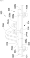
- the Fig. 4 shows a fastening system 300 according to a first embodiment of the invention and the Fig. 5 shows the 300 attachment system in cross-section.
- the fitting 208 here takes the form of a female yoke in which the element 206 is fixed, here by means of a bar 210.
- the fitting 208 here has a shoe 209 which is here a flat wall which allows the fixing of the fitting 208 to the fuselage 101 using fixing bolts 304 described below.
- the attachment system 300 comprises the fitting 208 and a plate 302.
- the plate 302 has a first face 302a and a second face 302b.
- the second face 302b is oriented towards the fuselage 101 and outside the latter.
- the plate 302 is fixed to the fuselage 101 by any suitable fixing means, such as screw elements, rivets, weld points, etc.
- the plate 302 is fixed to the fuselage 101 by means of several bolts 306 where each comprises a screw 306a with a head and a nut 306b.
- the plate 302 comprises through-bores 303 and the fuselage 101 comprises orifices 305 also through and positioned in alignment with the bores 303 when the plate 302 is pressed against the fuselage 101.
- the screw 306a of said bolt 306 passes through a bore 303 and the associated orifice 305 and the plate 302 and the fuselage 101 are thus sandwiched between the head of the screw 306a of said bolt 306 and the nut 306b of said bolt 306.
- each screw head 306a is a countersunk head inserted into a countersunk bore of the plate 302 on the side of the first face 302a and the nut 306b bears against the fuselage 101.
- the bolts 306 do not pass through the fitting 208.
- the holes 303 of the plate 302 are arranged so that there is no contact between the shoe 209 and the heads of the screws 306a in the assembled position.
- the plate 302 is wider than the shoe 209 and the holes 303 are outside and at a distance from the shoe 209.
- the shoe 209 of the fitting 208 has a contact face 208a which is in contact with the first face 302a of the plate 302.
- the plate 302 is thus between the fitting 208 and the fuselage 101.
- the fastening system 300 also comprises at least one fastening bolt 304, where each comprises a screw 304a and a nut 304b.
- the plate 302 comprises on the side of the second face 302b, a hole 308 passing through the plate 302, and which, in the form illustrated here is a countersunk hole, in which the head of the screw 304a is housed so as to be flush with the second face 302b which thus remains flat.
- Each nut 304b is screwed to the associated screw 304a by sandwiching the plate 302 and the fitting 208. Each nut 304b is thus against a bearing face 208b which is the face of the shoe 209 opposite the contact face 208a.
- the plate 302 thus constitutes a screen by preventing the disturbances (current, heat) from reaching the fuselage 101.
- the head of the screw 304a does not pass through the fuselage 101 and it is integrated into the plate 302 so that said head is flush with the second face 302b of the plate 302 and does not protrude relative to the latter.
- the screws 304a and the nuts 304b of the fixing bolts 304 make it possible to fix the plate 302 to the fitting 208 and therefore to the element 206 without passing through the fuselage 101, the fixing of the plate 302 on the fuselage 101 being carried out by the screws 306a and nuts 306b of the bolts 306.
- the plate 302 is advantageously made of a material which is arranged to limit the passage of heat and thus heating of the skid will result in limited heating of the fuselage 101.
- a material thus acts as a thermal insulator, and it can be made of MICA, glass fiber reinforced polymers, titanium alloy, carbon fiber reinforced polymers, etc.
- the plate 302 is advantageously made of a material which is arranged to prevent the passage of the current and thus a lightning strike. does not reach the fuselage 101.
- Such material acts as an electrical insulator, and it can be made of ABS, glass fiber reinforced polymers, etc.
- the plate 302 has a minimum electrical resistance of 1 ohm.
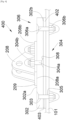
- FIG. 6 shows a fastening system 400 according to a second embodiment of the invention.
- the Fig. 4 also corresponds to the attachment system 400 according to the second embodiment of the invention.
- the elements identical to the first embodiment bear the same references.
- the attachment system 400 comprises an intermediate plate 402 which is arranged between the second face 302b of the plate 302 and the fuselage 101, so as to separate the screw heads 304a of each fixing bolt 304 from the fuselage 101.
- the intermediate plate 402 is thus on one side against the second face 302b of the plate 302 and on the other side against the fuselage 101.
- the intermediate plate 402 has a through bore 403 into which the screw 306a of said bolt 306 is inserted.
- this second embodiment is more particularly suitable in the case of induced currents, it can be implemented for the case relating to heat transfer.
- the intermediate plate 402 is made of the same material as the material constituting the plate 302, that is to say a thermally insulating material or an electrically insulating material.
- each nut 304b, 306b is covered with a cap 310 made of an electrically insulating material, such as ABS, glass fiber reinforced polymers, etc.
Landscapes
- Engineering & Computer Science (AREA)
- Aviation & Aerospace Engineering (AREA)
- Mechanical Engineering (AREA)
- General Engineering & Computer Science (AREA)
- Health & Medical Sciences (AREA)
- General Health & Medical Sciences (AREA)
- Pulmonology (AREA)
- Connection Of Plates (AREA)
Abstract
Description
- La présente invention concerne un aéronef comportant un système d'attache avec une ferrure pour fixer un élément tel qu'une canalisation ou un patin à un fuselage de l'aéronef.
- Un aéronef comporte classiquement un fuselage auquel deux ailes sont fixées et chaque aile supporte au moins un moteur, en particulier un turboréacteur. Au niveau de la partie centrale du fuselage, ce dernier est recouvert d'un carénage ventral.
- Certains éléments sont fixés à l'extérieur du fuselage, comme des canalisations d'air qui cheminent le long du fuselage entre le fuselage et le carénage ventral. Il peut arriver qu'une de ces canalisations se retrouve en partie en dehors du carénage ventral et soit alors en contact avec des éléments extérieurs, comme les moteurs, et si la foudre tombe sur le moteur, un courant électrique induit peut alors parcourir la canalisation.
- Pour éviter que le courant ne se propage au fuselage, voire à l'intérieur de ce dernier, la fixation de la canalisation au fuselage nécessite l'utilisation de matériaux spécifiques pouvant être relativement coûteux.
- Il est donc nécessaire de définir un arrangement permettant de réduire le coût nécessaire à la fixation d'une ferrure, en particulier métallique, à l'extérieur du fuselage tout en assurant une isolation électrique.
- De la même manière, pour diminuer les dégâts sur le fuselage lors d'un atterrissage en catastrophe, par exemple sans train d'atterrissage, il est prévu des patins qui sont fixés à l'extérieur du fuselage, et ces patins viennent alors glisser sur le tarmac. Ce glissement génère un échauffement du patin et il est donc souhaitable d'éviter que cet échauffement se transmette au fuselage et à l'intérieur de celui-ci. Pour éviter cet échauffement, des matériaux spécifiques et coûteux sont utilisés.
- Il est donc nécessaire de définir un arrangement permettant de réduire le coût nécessaire à la fixation d'une ferrure, en particulier métallique, à l'extérieur du fuselage tout en assurant une isolation thermique.
- D'une manière générale, il est nécessaire de trouver un arrangement qui permet de limiter le passage de perturbations comme un courant électrique ou un flux de chaleur vers le fuselage.
- Le document
US-B-7,898,785 divulgue un système de protection contre la foudre, où l'élément à protéger contre la foudre est à l'intérieur de l'aéronef. - Un objet de la présente invention est de proposer aéronef comportant un système d'attache avec une ferrure métallique pour fixer un élément à l'extérieur du fuselage de l'aéronef.
- À cet effet, est proposé un aéronef comportant un fuselage, un élément et au moins un système d'attache pour fixer l'élément à l'extérieur dudit fuselage, le système d'attache comportant :
- une plaque présentant une première face, et une deuxième face orientée vers le fuselage et où la plaque est fixée audit fuselage,
- une ferrure métallique fixée audit élément et présentant un sabot avec une face de contact en contact avec la première face, et
- au moins un boulon de fixation comportant une vis et un écrou, où la tête de la vis est logée dans la plaque du côté de la deuxième face et où l'écrou est vissé à la vis en prenant en sandwich la plaque et le sabot de la ferrure.
- Avec un tel système d'attache, cela permet de limiter le passage de perturbations comme un courant électrique ou un flux de chaleur vers le fuselage en incorporant une plaque tampon. Avantageusement, la plaque est constituée d'un matériau électriquement isolant arrangé pour empêcher le passage du courant.
- Avantageusement, la plaque est constituée d'un matériau thermiquement isolant arrangé pour limiter le passage de la chaleur.
- Avantageusement, le système d'attache comporte une plaque intermédiaire disposée contre la deuxième face de la plaque et destinée à être disposée contre le fuselage.
- Avantageusement, la plaque intermédiaire est constituée du même matériau que le matériau constituant la plaque.
- Avantageusement, la plaque est fixée au fuselage par des boulons où chacun comporte une vis avec une tête et un écrou, pour chaque boulon, la plaque comporte un perçage traversant et le fuselage comporte un orifice traversant et aligné avec le perçage, pour chaque boulon, la vis dudit boulon traverse un perçage et l'orifice associé de manière à prendre en sandwich la plaque et le fuselage entre la tête de la vis dudit boulon et l'écrou dudit boulon, et les perçages de la plaque sont arrangés de manière à ce qu'il n'y a aucun contact entre le sabot et les têtes des vis.
- Avantageusement, la plaque est plus large que le sabot et les perçages sont à l'extérieur et à distance du sabot.
- Les caractéristiques de l'invention mentionnées ci-dessus, ainsi que d'autres, apparaîtront plus clairement à la lecture de la description suivante d'un exemple de réalisation, ladite description étant faite en relation avec les dessins joints, parmi lesquels :
-
Fig. 1 est une vue de côté d'un aéronef selon l'invention, -
Fig. 2 est une vue en coupe partielle selon la ligne II-II de la partie basse du fuselage de l'aéronef de laFig. 1 , -
Fig. 3 est une vue en perspective d'une implantation particulière d'un système d'attache selon l'invention, -
Fig. 4 est une vue de dessus d'un système d'attache selon l'invention, -
Fig. 5 est une vue en coupe selon la ligne V-V de laFig. 4 d'un système d'attache selon un premier mode de réalisation de l'invention, et -
Fig. 6 est une vue en coupe selon la ligne V-V de laFig. 4 d'un système d'attache selon un deuxième mode de réalisation de l'invention. - Dans la description qui suit, les termes relatifs à une position sont pris en référence à un aéronef en position d'avancement, c'est-à-dire comme il est représenté sur la
Fig. 1 , où la flèche F représente la direction d'avancement. - La
Fig. 1 montre un aéronef 100 qui présente un fuselage 101 de part et d'autre duquel est fixée une aile 106 qui porte chacune au moins un moteur 102, en particulier un turboréacteur, ici par l'intermédiaire d'un mât réacteur 104. - Dans la description qui suit, et par convention, on appelle X la direction longitudinale de l'aéronef 100 orientée positivement dans le sens d'avancement de l'aéronef 100, on appelle Y la direction transversale de l'aéronef 100 qui est horizontale lorsque l'aéronef 100 est au sol, et Z la direction verticale ou hauteur verticale lorsque l'aéronef 100 est au sol, ces trois directions X, Y et Z étant orthogonales entre elles.
- La
Fig. 2 montre une coupe par un plan vertical du fuselage 101. Au niveau de la partie centrale du fuselage 101, l'aéronef 100 comporte un carénage ventral 202 qui est solidaire du fuselage 101 et qui est à l'extérieur de ce dernier pour délimiter entre eux un espace 204 dans lequel au moins un élément 206 de l'aéronef 100 est arrangé. Le carénage ventral 202 permet entre autres de protéger l'élément 206 des impacts directs de la foudre. - Dans le mode de réalisation de l'invention présenté ici, l'élément 206 est une canalisation, comme une canalisation d'air alimentant par exemple un moteur 102, mais il peut s'agir d'un autre élément. Par exemple, l'élément 206 peut être un patin, destiné à assurer que l'aéronef 100 glisse sur le tarmac en cas d'atterrissage sans train d'atterrissage par exemple. L'élément 206 est fixé au fuselage 101 par au moins une ferrure 208 solidaire du fuselage 101. Dans le mode de réalisation de l'invention présenté à la
Fig. 2 , l'élément 206 comporte ici des barres 210 qui sont fixées aux ferrures 208. - La
Fig. 3 montre les mêmes éléments que ceux de laFig. 2 mais sans le carénage ventral 202. LaFig. 4 montre un système d'attache 300 selon un premier mode de réalisation de l'invention et laFig. 5 montre le système d'attache 300 en coupe. - La ferrure 208 prend ici la forme d'une chape femelle dans laquelle se fixe l'élément 206, ici par l'intermédiaire d'une barre 210. La ferrure 208 présente ici un sabot 209 qui est ici une paroi plane qui permet la fixation de la ferrure 208 au fuselage 101 à l'aide de boulons de fixation 304 décrits ci-dessous.
- Le système d'attache 300 comporte la ferrure 208 et une plaque 302.
- La plaque 302 présente une première face 302a et une deuxième face 302b. La deuxième face 302b est orientée vers le fuselage 101 et à l'extérieur de ce dernier.
- La plaque 302 est fixée au fuselage 101 par tous moyens de fixation appropriés, comme des éléments de visserie, des rivets, des points de soudure, etc.
- Dans le mode de réalisation de l'invention présenté ici, la plaque 302 est fixée au fuselage 101 par l'intermédiaire de plusieurs boulons 306 où chacun comporte une vis 306a avec une tête et un écrou 306b. À cette fin, la plaque 302 comporte des perçages 303 traversants et le fuselage 101 comporte des orifices 305 également traversants et positionnés en alignement avec les perçages 303 lorsque la plaque 302 est plaquée contre le fuselage 101. Pour chaque boulon 306, la vis 306a dudit boulon 306 traverse un perçage 303 et l'orifice 305 associé et la plaque 302 et le fuselage 101 sont ainsi pris en sandwich entre la tête de la vis 306a dudit boulon 306 et l'écrou 306b dudit boulon 306. Dans le mode de réalisation de l'invention présenté à la
Fig. 5 , chaque tête de vis 306a est une tête fraisée insérée dans un alésage fraisé de la plaque 302 du côté de la première face 302a et l'écrou 306b est en appui contre le fuselage 101. Les boulons 306 ne traversent pas la ferrure 208. - Pour empêcher le passage du courant ou de la chaleur entre le sabot 209 et les boulons 306, les perçages 303 de la plaque 302 sont arrangés de manière à ce qu'il n'y a aucun contact entre le sabot 209 et les têtes des vis 306a en position assemblée. Dans le mode de réalisation de l'invention présenté ici, la plaque 302 est plus large que le sabot 209 et les perçages 303 sont à l'extérieur et à distance du sabot 209.
- Le sabot 209 de la ferrure 208 présente une face de contact 208a qui est en contact avec la première face 302a de la plaque 302. La plaque 302 est ainsi entre la ferrure 208 et le fuselage 101.
- Le système d'attache 300 comporte également au moins un boulon de fixation 304, où chacun comporte une vis 304a et un écrou 304b.
- Pour chaque boulon de fixation 304, la plaque 302 comporte du côté de la deuxième face 302b, un trou 308 traversant la plaque 302, et qui, dans la forme illustrée est ici un trou fraisé, dans lequel la tête de la vis 304a est logée de manière à affleurer la deuxième face 302b qui reste ainsi plane.
- Chaque écrou 304b est vissé à la vis 304a associée en prenant en sandwich la plaque 302 et la ferrure 208. Chaque écrou 304b est ainsi contre une face d'appui 208b qui est la face du sabot 209 opposée à la face de contact 208a.
- Avec un tel assemblage, il est possible de protéger le fuselage 101 des éventuelles perturbations provenant de l'élément 206 à travers la ferrure 208, comme un courant électrique ou un flux de chaleur. La plaque 302 constitue ainsi un écran en empêchant les perturbations (courant, chaleur) d'atteindre le fuselage 101.
- La tête de la vis 304a ne traverse pas le fuselage 101 et elle est intégrée à la plaque 302 de manière à ce que ladite tête soit affleurante avec la deuxième face 302b de la plaque 302 et ne dépasse pas par rapport à celle-ci.
- Les vis 304a et les écrous 304b des boulons de fixation 304 permettent de fixer la plaque 302 à la ferrure 208 et donc à l'élément 206 sans traverser le fuselage 101, la fixation de la plaque 302 sur le fuselage 101 étant réalisée par les vis 306a et écrous 306b des boulons 306.
- Par exemple, dans le cas où l'élément 206 est un patin, la plaque 302 est avantageusement constituée d'un matériau qui est arrangé pour limiter le passage de la chaleur et ainsi un échauffement du patin entraînera un échauffement limité du fuselage 101. Un tel matériau agit ainsi comme un isolant thermique, et il peut être réalisé en MICA, en polymères renforcés de fibres de verre, en alliage de titane, en polymères renforcés de fibres de carbone, etc.
- Par exemple, dans le cas où l'élément 206 est une canalisation susceptible de recevoir un impact de foudre qui pourrait induire un courant dans la canalisation et dans la ferrure 208, en particulier lorsqu'elle est métallique, la plaque 302 est avantageusement constituée d'un matériau qui est arrangé pour empêcher le passage du courant et ainsi un impact de foudre n'atteint pas le fuselage 101. Un tel matériau agit comme un isolant électrique, et il peut être réalisé en ABS, en polymères renforcés de fibres de verre, etc.
- Du fait de la présence du carénage ventral 202, les boulons 306 ne peuvent pas être atteints directement par un potentiel impact de foudre.
- Selon un mode de réalisation particulier, la plaque 302 présente une résistance électrique minimale de 1 ohm.
- La
Fig. 6 montre un système d'attache 400 selon un deuxième mode de réalisation de l'invention. LaFig. 4 correspond également au système d'attache 400 selon le deuxième mode de réalisation de l'invention. Les éléments identiques au premier mode de réalisation portent les mêmes références. - Pour limiter encore plus le passage des éventuels courants électriques entre la ferrure 208 et le fuselage 101, le système d'attache 400 comporte une plaque intermédiaire 402 qui est disposée entre la deuxième face 302b de la plaque 302 et le fuselage 101, de manière à séparer les têtes de vis 304a de chaque boulon de fixation 304 du fuselage 101. La plaque intermédiaire 402 est ainsi d'un côté contre la deuxième face 302b de la plaque 302 et de l'autre côté contre le fuselage 101.
- Pour chaque boulon 306, la plaque intermédiaire 402 présente un alésage 403 traversant dans lequel s'introduit la vis 306a dudit boulon 306.
- Bien que ce deuxième mode de réalisation soit plus particulièrement adapté dans le cas de courants induits, il peut être mis en oeuvre pour le cas relatif au transfert de chaleur.
- Selon le cas, la plaque intermédiaire 402 est constituée du même matériau que le matériau constituant la plaque 302, c'est-à-dire un matériau thermiquement isolant ou un matériau électriquement isolant.
- Dans les modes de réalisation de l'invention présentés sur les
Figs. 5 et6 , chaque écrou 304b, 306b est recouvert d'un capuchon 310 réalisé dans un matériau électriquement isolant, comme de l'ABS, des polymères renforcés de fibres de verre, etc.
Claims (7)
- Aéronef (100) comportant un fuselage (101), un élément (206) et au moins un système d'attache (300, 400) pour fixer l'élément (206) à l'extérieur dudit fuselage (101), le système d'attache (300, 400) comportant :- une plaque (302) présentant une première face (302a) et une deuxième face (302b) orientée vers le fuselage (101), et où la plaque (302) est fixée audit fuselage (101),- une ferrure (208) métallique fixée audit élément (206) et présentant un sabot (209) avec une face de contact (208a) en contact avec la première face (302a), et- au moins un boulon de fixation (304) comportant une vis (304a) et un écrou (304b), où la tête de la vis (304a) est logée dans la plaque (302) du côté de la deuxième face (302b) et où l'écrou (304b) est vissé à la vis (304a) en prenant en sandwich la plaque (302) et le sabot (209) de la ferrure (208).
- Aéronef (100) selon la revendication 1, caractérisé en ce que la plaque (302) est constituée d'un matériau électriquement isolant arrangé pour empêcher le passage du courant.
- Aéronef (100) selon la revendication 1, caractérisé en ce que la plaque (302) est constituée d'un matériau thermiquement isolant arrangé pour limiter le passage de la chaleur.
- Aéronef (100) selon l'une des revendications 1 à 3, caractérisé en ce qu'il comporte une plaque intermédiaire (402) disposée contre la deuxième face (302b) de la plaque (302) et destinée à être disposée contre le fuselage (101).
- Aéronef (100) selon la revendication 4, caractérisé en ce que la plaque intermédiaire (402) est constituée du même matériau que le matériau constituant la plaque (302).
- Aéronef (100) selon l'une des revendications 1 à 5, caractérisé en ce que la plaque (302) est fixée au fuselage (101) par des boulons (306) où chacun comporte une vis (306a) avec une tête et un écrou (306b), en ce que pour chaque boulon (306), la plaque (302) comporte un perçage (303) traversant et le fuselage (101) comporte un orifice (305) traversant et aligné avec le perçage (303), en ce que pour chaque boulon (306), la vis (306a) dudit boulon (306) traverse un perçage (303) et l'orifice (305) associé de manière à prendre en sandwich la plaque (302) et le fuselage (101) entre la tête de la vis (306a) dudit boulon (306) et l'écrou (306b) dudit boulon (306), et en ce que les perçages (303) de la plaque (302) sont arrangés de manière à ce qu'il n'y a aucun contact entre le sabot (209) et les têtes des vis (306a).
- Aéronef (100) selon la revendication 6, caractérisé en ce que la plaque (302) est plus large que le sabot (209) et les perçages (303) sont à l'extérieur et à distance du sabot (209).
Applications Claiming Priority (1)
| Application Number | Priority Date | Filing Date | Title |
|---|---|---|---|
| FR2306863 | 2023-06-29 |
Publications (2)
| Publication Number | Publication Date |
|---|---|
| EP4484765A1 true EP4484765A1 (fr) | 2025-01-01 |
| EP4484765B1 EP4484765B1 (fr) | 2026-03-25 |
Family
ID=88839896
Family Applications (1)
| Application Number | Title | Priority Date | Filing Date |
|---|---|---|---|
| EP24184552.8A Active EP4484765B1 (fr) | 2023-06-29 | 2024-06-26 | Aéronef comportant un système d attache d'un élément à un fuselage et comportant un écran anti-foudre |
Country Status (3)
| Country | Link |
|---|---|
| US (1) | US20250002134A1 (fr) |
| EP (1) | EP4484765B1 (fr) |
| CN (1) | CN119218404A (fr) |
Citations (3)
| Publication number | Priority date | Publication date | Assignee | Title |
|---|---|---|---|---|
| US7898785B2 (en) | 2006-12-07 | 2011-03-01 | The Boeing Company | Lightning protection system for an aircraft composite structure |
| US20120236457A1 (en) * | 2011-03-16 | 2012-09-20 | Mitsubishi Aircraft Corporation | Lightning protection fastener, aircraft assembly, and method of manufacturing aircraft assembly component |
| US20140110526A1 (en) * | 2012-10-18 | 2014-04-24 | Embraer S.A. | Assemblies for external attachment of airborne sensor pods to an aircraft fuselage |
Family Cites Families (8)
| Publication number | Priority date | Publication date | Assignee | Title |
|---|---|---|---|---|
| EP1628879B1 (fr) * | 2003-05-30 | 2006-09-20 | BAE Systems PLC | Protection contre la foudre d'une structure composite |
| US7731127B2 (en) * | 2005-05-18 | 2010-06-08 | Airbus Deutschland Gmbh | Drain mast connector |
| EP2455286B1 (fr) * | 2010-11-22 | 2016-09-28 | Airbus Defence and Space SA | Protection contre la foudre pour structures composites d'avions |
| GB201101311D0 (en) * | 2011-01-26 | 2011-03-09 | Airbus Uk Ltd | Fastener assembly |
| US10279926B2 (en) * | 2014-03-28 | 2019-05-07 | Bombardier Inc. | Lightning protection for aircraft antenna avionics |
| US9537207B2 (en) * | 2014-12-11 | 2017-01-03 | Thales, Inc. | Antenna assembly with a multi-band radome and associated methods |
| FR3067868B1 (fr) * | 2017-06-16 | 2019-08-02 | Dassault Aviation | Systeme parafoudre et nez associe |
| GB2575105A (en) * | 2018-06-29 | 2020-01-01 | Airbus Operations Ltd | A duct stringer |
-
2024
- 2024-06-26 EP EP24184552.8A patent/EP4484765B1/fr active Active
- 2024-06-27 US US18/755,821 patent/US20250002134A1/en active Pending
- 2024-07-01 CN CN202410870602.6A patent/CN119218404A/zh active Pending
Patent Citations (3)
| Publication number | Priority date | Publication date | Assignee | Title |
|---|---|---|---|---|
| US7898785B2 (en) | 2006-12-07 | 2011-03-01 | The Boeing Company | Lightning protection system for an aircraft composite structure |
| US20120236457A1 (en) * | 2011-03-16 | 2012-09-20 | Mitsubishi Aircraft Corporation | Lightning protection fastener, aircraft assembly, and method of manufacturing aircraft assembly component |
| US20140110526A1 (en) * | 2012-10-18 | 2014-04-24 | Embraer S.A. | Assemblies for external attachment of airborne sensor pods to an aircraft fuselage |
Also Published As
| Publication number | Publication date |
|---|---|
| EP4484765B1 (fr) | 2026-03-25 |
| US20250002134A1 (en) | 2025-01-02 |
| CN119218404A (zh) | 2024-12-31 |
Similar Documents
| Publication | Publication Date | Title |
|---|---|---|
| EP2190739B1 (fr) | Carenage aerodynamique arriere inferieur pour dispositif d'accrochage d'un moteur d'aeronef | |
| EP2139768B1 (fr) | Mat d'accrochage de moteur pour aeronef disposant d'une attache moteur arriere pourvue d'un ecrou a barillet | |
| EP2146898B1 (fr) | Carenage aerodynamique arriere inferieur pour dispositif d' accrochage d' un moteur d' aeronef | |
| EP1883578B1 (fr) | Ensemble moteur pour aéronef | |
| EP2500268B1 (fr) | Mât d'accrochage de moteur pour aéronef | |
| FR3015431A1 (fr) | Structure primaire de mat d'accrochage renforcee. | |
| EP1931567B1 (fr) | Mat d'accrochage de turboreacteur pour aeronef | |
| CA2781013C (fr) | Carenage aerodynamique arriere d'un mat de liaison d'un moteur d'aeronef | |
| EP4296157B1 (fr) | Aéronef comportant un fuselage et un panneau fixé de manière amovible au fuselage à l'aide de moyens de fixation | |
| EP4484297B1 (fr) | Système d'attache moteur avant pour un moteur d'aéronef qui comporte une structure compacte | |
| EP2072396A2 (fr) | Carter intermediaire pour turboreacteur d'aeronef a conception amelioree | |
| EP4484298A1 (fr) | Système d attache moteur avant pour un moteur d aéronef qui comporte une structure compacte | |
| EP4484765B1 (fr) | Aéronef comportant un système d attache d'un élément à un fuselage et comportant un écran anti-foudre | |
| EP4148254B1 (fr) | Ensemble pour une nacelle d'aéronef et comportant un panneau support, une protection thermique et un système de fixation | |
| FR3121428A1 (fr) | Mât réacteur d’aéronef comportant un ensemble mobile de capots | |
| FR3156756A1 (fr) | Ensemble propulsif pour aéronef comportant un moteur, un mât et des moyens d’accrochage du moteur au mât | |
| FR3141676A1 (fr) | Ensemble pour un aéronef comportant une aile et un mât réacteur pour coupler un système de propulsion à ladite aile | |
| EP3581781B1 (fr) | Systeme de propulsion d'un aeronef comportant une structure interieure fixe presentant une fente d'evacuation | |
| EP3560827A1 (fr) | Atterriseur pourvu d'un dispositif pare-foudre | |
| EP4717587A1 (fr) | Dispositif de protection thermique d'un longeron inférieur d'un caisson d'aéronef | |
| EP3575209A1 (fr) | Aéronef comprenant une paroi aérodynamique et au moins un générateur de tourbillons | |
| EP4129825B1 (fr) | Ensemble pour une nacelle d'un moteur d'aéronef, ledit ensemble comportant un capot fixe et un capot monté mobile sur le capot fixe | |
| EP4067227B1 (fr) | Nacelle d'aéronef comportant un système de joint avec ressort pour une casquette de ladite nacelle | |
| FR3156118A1 (fr) | Mât réacteur pour le montage sur un aéronef d’un système de propulsion | |
| EP4682055A1 (fr) | Mât réacteur comportant une structure primaire et une structure secondaire avant avec des moyens de fixation de l'une à l'autre |
Legal Events
| Date | Code | Title | Description |
|---|---|---|---|
| PUAI | Public reference made under article 153(3) epc to a published international application that has entered the european phase |
Free format text: ORIGINAL CODE: 0009012 |
|
| STAA | Information on the status of an ep patent application or granted ep patent |
Free format text: STATUS: THE APPLICATION HAS BEEN PUBLISHED |
|
| AK | Designated contracting states |
Kind code of ref document: A1 Designated state(s): AL AT BE BG CH CY CZ DE DK EE ES FI FR GB GR HR HU IE IS IT LI LT LU LV MC ME MK MT NL NO PL PT RO RS SE SI SK SM TR |
|
| STAA | Information on the status of an ep patent application or granted ep patent |
Free format text: STATUS: REQUEST FOR EXAMINATION WAS MADE |
|
| 17P | Request for examination filed |
Effective date: 20250626 |
|
| GRAP | Despatch of communication of intention to grant a patent |
Free format text: ORIGINAL CODE: EPIDOSNIGR1 |
|
| STAA | Information on the status of an ep patent application or granted ep patent |
Free format text: STATUS: GRANT OF PATENT IS INTENDED |
|
| INTG | Intention to grant announced |
Effective date: 20251024 |
|
| GRAS | Grant fee paid |
Free format text: ORIGINAL CODE: EPIDOSNIGR3 |
|
| GRAA | (expected) grant |
Free format text: ORIGINAL CODE: 0009210 |
|
| STAA | Information on the status of an ep patent application or granted ep patent |
Free format text: STATUS: THE PATENT HAS BEEN GRANTED |
|
| AK | Designated contracting states |
Kind code of ref document: B1 Designated state(s): AL AT BE BG CH CY CZ DE DK EE ES FI FR GB GR HR HU IE IS IT LI LT LU LV MC ME MK MT NL NO PL PT RO RS SE SI SK SM TR |
|
| REG | Reference to a national code |
Ref country code: CH Ref legal event code: F10 Free format text: ST27 STATUS EVENT CODE: U-0-0-F10-F00 (AS PROVIDED BY THE NATIONAL OFFICE) Effective date: 20260325 Ref country code: GB Ref legal event code: FG4D Free format text: NOT ENGLISH |
|
| REG | Reference to a national code |
Ref country code: DE Ref legal event code: R096 Ref document number: 602024003388 Country of ref document: DE |
|
| REG | Reference to a national code |
Ref country code: IE Ref legal event code: FG4D Free format text: LANGUAGE OF EP DOCUMENT: FRENCH |