EP4484755A1 - Fluid transport device, liquid cooling device, refrigeration device, and method for detecting state of fluid transport device - Google Patents
Fluid transport device, liquid cooling device, refrigeration device, and method for detecting state of fluid transport device Download PDFInfo
- Publication number
- EP4484755A1 EP4484755A1 EP23779595.0A EP23779595A EP4484755A1 EP 4484755 A1 EP4484755 A1 EP 4484755A1 EP 23779595 A EP23779595 A EP 23779595A EP 4484755 A1 EP4484755 A1 EP 4484755A1
- Authority
- EP
- European Patent Office
- Prior art keywords
- fluid
- fan
- change
- flow path
- state
- Prior art date
- Legal status (The legal status is an assumption and is not a legal conclusion. Google has not performed a legal analysis and makes no representation as to the accuracy of the status listed.)
- Pending
Links
Images





Classifications
-
- F—MECHANICAL ENGINEERING; LIGHTING; HEATING; WEAPONS; BLASTING
- F25—REFRIGERATION OR COOLING; COMBINED HEATING AND REFRIGERATION SYSTEMS; HEAT PUMP SYSTEMS; MANUFACTURE OR STORAGE OF ICE; LIQUEFACTION SOLIDIFICATION OF GASES
- F25B—REFRIGERATION MACHINES, PLANTS OR SYSTEMS; COMBINED HEATING AND REFRIGERATION SYSTEMS; HEAT PUMP SYSTEMS
- F25B13/00—Compression machines, plants or systems, with reversible cycle
-
- F—MECHANICAL ENGINEERING; LIGHTING; HEATING; WEAPONS; BLASTING
- F04—POSITIVE - DISPLACEMENT MACHINES FOR LIQUIDS; PUMPS FOR LIQUIDS OR ELASTIC FLUIDS
- F04D—NON-POSITIVE-DISPLACEMENT PUMPS
- F04D25/00—Pumping installations or systems
- F04D25/02—Units comprising pumps and their driving means
- F04D25/08—Units comprising pumps and their driving means the working fluid being air, e.g. for ventilation
-
- F—MECHANICAL ENGINEERING; LIGHTING; HEATING; WEAPONS; BLASTING
- F04—POSITIVE - DISPLACEMENT MACHINES FOR LIQUIDS; PUMPS FOR LIQUIDS OR ELASTIC FLUIDS
- F04D—NON-POSITIVE-DISPLACEMENT PUMPS
- F04D27/00—Control, e.g. regulation, of pumps, pumping installations or pumping systems specially adapted for elastic fluids
- F04D27/001—Testing thereof; Determination or simulation of flow characteristics; Stall or surge detection, e.g. condition monitoring
-
- F—MECHANICAL ENGINEERING; LIGHTING; HEATING; WEAPONS; BLASTING
- F25—REFRIGERATION OR COOLING; COMBINED HEATING AND REFRIGERATION SYSTEMS; HEAT PUMP SYSTEMS; MANUFACTURE OR STORAGE OF ICE; LIQUEFACTION SOLIDIFICATION OF GASES
- F25B—REFRIGERATION MACHINES, PLANTS OR SYSTEMS; COMBINED HEATING AND REFRIGERATION SYSTEMS; HEAT PUMP SYSTEMS
- F25B25/00—Machines, plants or systems, using a combination of modes of operation covered by two or more of the groups F25B1/00 - F25B23/00
- F25B25/005—Machines, plants or systems, using a combination of modes of operation covered by two or more of the groups F25B1/00 - F25B23/00 using primary and secondary systems
-
- F—MECHANICAL ENGINEERING; LIGHTING; HEATING; WEAPONS; BLASTING
- F25—REFRIGERATION OR COOLING; COMBINED HEATING AND REFRIGERATION SYSTEMS; HEAT PUMP SYSTEMS; MANUFACTURE OR STORAGE OF ICE; LIQUEFACTION SOLIDIFICATION OF GASES
- F25B—REFRIGERATION MACHINES, PLANTS OR SYSTEMS; COMBINED HEATING AND REFRIGERATION SYSTEMS; HEAT PUMP SYSTEMS
- F25B49/00—Arrangement or mounting of control or safety devices
- F25B49/005—Arrangement or mounting of control or safety devices of safety devices
-
- F—MECHANICAL ENGINEERING; LIGHTING; HEATING; WEAPONS; BLASTING
- F05—INDEXING SCHEMES RELATING TO ENGINES OR PUMPS IN VARIOUS SUBCLASSES OF CLASSES F01-F04
- F05D—INDEXING SCHEME FOR ASPECTS RELATING TO NON-POSITIVE-DISPLACEMENT MACHINES OR ENGINES, GAS-TURBINES OR JET-PROPULSION PLANTS
- F05D2270/00—Control
- F05D2270/30—Control parameters, e.g. input parameters
- F05D2270/301—Pressure
- F05D2270/3015—Pressure differential pressure
-
- F—MECHANICAL ENGINEERING; LIGHTING; HEATING; WEAPONS; BLASTING
- F05—INDEXING SCHEMES RELATING TO ENGINES OR PUMPS IN VARIOUS SUBCLASSES OF CLASSES F01-F04
- F05D—INDEXING SCHEME FOR ASPECTS RELATING TO NON-POSITIVE-DISPLACEMENT MACHINES OR ENGINES, GAS-TURBINES OR JET-PROPULSION PLANTS
- F05D2270/00—Control
- F05D2270/30—Control parameters, e.g. input parameters
- F05D2270/335—Output power or torque
-
- F—MECHANICAL ENGINEERING; LIGHTING; HEATING; WEAPONS; BLASTING
- F25—REFRIGERATION OR COOLING; COMBINED HEATING AND REFRIGERATION SYSTEMS; HEAT PUMP SYSTEMS; MANUFACTURE OR STORAGE OF ICE; LIQUEFACTION SOLIDIFICATION OF GASES
- F25B—REFRIGERATION MACHINES, PLANTS OR SYSTEMS; COMBINED HEATING AND REFRIGERATION SYSTEMS; HEAT PUMP SYSTEMS
- F25B2313/00—Compression machines, plants or systems with reversible cycle not otherwise provided for
- F25B2313/003—Indoor unit with water as a heat sink or heat source
Definitions
- the present disclosure relates to a fluid transfer apparatus, a fluid cooling apparatus and a refrigeration apparatus, and a state detecting method of the fluid transfer apparatus.
- Patent Document 1 Japanese Unexamined Patent Application Publication No. H11-290630
- the present disclosure provides a fluid transfer apparatus, a fluid cooling apparatus, a refrigeration apparatus, and a state detection method of the fluid transfer apparatus, which can highly accurately detect the state of a fluid transferred by a fan along a flow path or the state of a structure through which the fluid passes.
- a fluid transfer apparatus including:
- the state of the fluid or the state of the structure can be detected with high accuracy while reducing the influence of a temperature variation of an atmosphere and a power supply voltage variation.
- the state of the fluid detected by the detecting unit may include an amount correlated with a magnitude of the pressure loss generated in the flow path.
- the amount correlated with the magnitude of the pressure loss generated in the flow path can be detected with high accuracy.
- the state of the structure detected by the detecting unit may include clogging of the structure.
- the phenomenon may be a change in a current, a voltage, or a power of a motor driving the fan.
- the change in the current, voltage, or power of the motor driving the fan is a phenomenon having a high correlation with the variation in the force caused by the disturbance
- the state of the fluid or the state of the structure can be detected with high accuracy by monitoring the change in the current, voltage, or power of the motor driving the fan.
- the phenomenon may be a change in a rotation speed of the fan.
- the change in the rotation speed of the fan is a phenomenon having a high correlation with the variation in the force caused by the disturbance
- the state of the fluid or the state of the structure can be detected with high accuracy by monitoring the change in the rotation speed of the fan.
- the phenomenon may be a change in sound or vibration caused by the rotational motion of the fan.
- the state of the fluid or the state of the structure can be detected with high accuracy by monitoring the change in the sound or the vibration caused by the rotational motion of the fan.
- the phenomenon may be a change in a frequency spectrum of the current, the voltage, or the power of the motor driving the fan.
- the change in the frequency spectrum of the current, voltage, or power of the motor driving the fan is a phenomenon having high correlation with the variation in the force caused by the disturbance, the state of the fluid or the state of the structure can be detected with high accuracy by monitoring the change in the frequency spectrum.
- the change in the frequency spectrum may be a change associated with a change in a frequency of a highest spectral intensity.
- a change in the frequency spectrum when a phenomenon occurs in which a frequency having the largest spectral intensity fluctuates is a phenomenon having a high correlation with a variation in the force caused by the disturbance. Therefore, by monitoring a change in the frequency spectrum when a phenomenon occurs in which a frequency having the largest spectral intensity fluctuates, the state of the fluid or the state of the structure can be detected with high accuracy.
- the change in the frequency spectrum may be a change in a spectral intensity of the current at a specific frequency within a machine angular frequency of the motor ⁇ N (N being a natural number) ⁇ a (a ⁇ the machine angular frequency/20).
- the change in the spectral intensity of the current at a specific frequency within the machine angular frequency of the motor ⁇ N (N is a natural number) ⁇ a (a ⁇ the machine angular frequency/20) is a phenomenon having a high correlation with the variation of the force caused by the disturbance. Therefore, by monitoring the change in the spectral intensity of the current at the specific frequency, the state of the fluid or the state of the structure can be detected with high accuracy.
- the current may be a direct current amount correlated with a torque of the motor.
- the state of the fluid or the state of the structure can be detected with high accuracy by monitoring a change in the spectral intensity of the DC amount at the specific frequency.
- the current is a direct current amount correlated with a torque of the motor
- the change in the frequency spectrum may be a change in a spectral intensity of the current at a specific frequency within a machine angular frequency of the motor ⁇ a number of blades of the fan ⁇ N (N being a natural number) ⁇ a (a ⁇ the machine angular frequency/20).
- the filter 13 has a filter material formed of, for example, a nonwoven fabric.
- the shape of the filter material may be flat, pleated, net-like, or roll-like, but is not limited thereto.
- FIG. 5 is a partial cross-sectional view schematically illustrating the longitudinal cross-section B-B of FIG. 3 .
- the filter 13, the condenser 3, and the fan 6 are arranged in the housing 11 in the order of the filter 13, the condenser 3, and the fan 6 from the intake port 12 side.
- outside air is taken in from the intake port 12 through the filter 13 by rotation of the fan 6, supplied to the condenser 3, and then discharged from the blowout port 14.
- the housing 11 has, for example, a bottom frame 30 that covers the lower side of the housing 11.
- the bottom frame 30 has an oil reservoir 33 provided below the condenser 3 and the filter 13.
- the oil reservoir 33 receives and stores oil droplets from the condenser 3 and the filter 13.
- the oil reservoir 33 is also referred to as an oil pan.
- the oil reservoir 33 may be formed integrally with the bottom frame 30 or may be provided separately from the bottom frame 30.
- the motor 7 is an electric motor for rotating the fan 6.
- the rotating shaft of the motor 7 is connected directly or via a gear to the center of rotation of the fan 6.
- the motor 7 is controlled by the control device 50.
- the motor 7 may be arranged in the flow path 71 or outside the flow path 71. By arranging the motor 7 in the flow path 71, the motor 7 can be cooled by air A.
- the condenser 3 is an example of a structure provided in the flow path 71 and having a passage through which air A passes.
- the condenser 3 is a structure through which air A passes, and is provided at a position somewhere along the flow path 71.
- the condenser 3 is a heat exchanger that liquefies a high-pressure, high-temperature gas refrigerant by exchanging heat with air A.
- the condenser 3 is arranged between the filter 13 and the fan 6.
- the gap between the plurality of fins 3a arranged as illustrated in FIG. 4 corresponds to a passage through which air A passes.
- the control device 50 has a driving circuit 51 that drives the motor 7 by switching a plurality of semiconductor switching elements.
- the driving circuit 51 supplies a drive current to the motor 7, and the motor 7 rotates the fan 6 when the drive current is supplied from the driving circuit 51.
- the driving circuit 51 is, for example, an inverter circuit that converts a direct current from a direct current source into an alternating current that is supplied to the motor 7.
- the heat of the driving circuit 51 is transferred to the heat sink 52. Because the heat sink 52 is arranged in the flow path 71, the heat sink 52 is cooled by the air A, and the heat dissipation effect of the heat sink 52 on the driving circuit 51 is improved.
- the control device 50 is separated from the flow path 71 by the inner wall 72, but the control device 50 may be arranged in the flow path 71.
- the driving circuit 51 may be arranged at a different location from the control device 50.
- the filter 13 is a structure that generates a pressure loss in the flow path 71 when the air A passes through the filter 13.
- the condenser 3 is a structure that generates a pressure loss in the flow path 71 when the air A passes through the condenser 3.
- the control device 50 controls the rotation speed of the fan 6 or the motor 7 to be constant, the average rotation speed of the fan 6 becomes constant, although the rotation speed of the fan 6 fluctuates slightly.
- the pressure loss in the flow path 71 increases.
- the disturbance refers to a state in which the flow direction of the fluid, the flow velocity of the fluid, or the pressure of the fluid fluctuates irregularly.
- the flow direction of the fluid and the flow velocity of the fluid can be measured by using, for example, a flow velocity sensor (electromagnetic type, ultrasonic type, Karman vortex type, thermal type, etc.) or the like, or particle image velocimetry (PIV).
- the pressure of the fluid can be measured by using, for example, a strain gauge sensor or the like.
- FIG. 6 is a correlation block diagram illustrating the influence of a state of clogging or the like.
- a state of clogging or the like occurs in the filter 13 or the condenser 3, the degree of turbulence (disturbance) of the air A in the flow path 71 increases.
- the variation of the force F applied to the blades 8 (variation of the load applied to the fan 6) is disturbed.
- the variation of the load variation of the fan 6 increases the variation of the rotation speed of the fan 6, although the average rotation speed of the fan 6 is constant.
- the variation of the rotation speed of the fan 6 increases, the variation of the phase current flowing through the motor 7 that drives the fan 6 also increases.
- the control device 50 illustrated in FIG. 5 functions as a detecting unit that monitors a phenomenon correlated with the variation of the force F due to the disturbance of the air A and detects, for example, the state of the air A or the state of the structure through which the air A passes.
- the variation of the force F due to the disturbance of the air A means a state in which the variation of the force F increases due to the disturbance of the air A.
- the control device 50 has such a function as a detecting unit, it is possible to detect the state of the fluid such as the disturbance of the air A or the state of the structure such as the clogging of the filter 13 or the condenser 3 with high accuracy by monitoring the phenomenon correlated with the variation of the force F caused by the disturbance of the air A.
- the control device 50 may detect the state of the fluid such as the disturbance of the air A or the state of the structure such as the clogging of the filter 13 or the condenser 3 by monitoring, for example, the change in the phase current flowing through the motor 7 with the current sensor.
- the control device 50 may detect the state of the fluid such as the disturbance of the air A or the state of the structure such as the clogging of the filter 13 or the condenser 3 by monitoring, for example, the change in the voltage generated in the motor 7 with the voltage sensor.
- the control device 50 may detect the state of the fluid such as the disturbance of the air A or the state of the structure such as the clogging of the filter 13 or the condenser 3 by monitoring, for example, the change in the power input/output to the motor 7 with the current sensor and the voltage sensor. Because the current sensor and the voltage sensor for detecting the current, voltage, and power of the motor 7 are already provided for fan control, it is not necessary to separately provide the aforementioned flow velocity sensor or the like in order to detect the disturbance of the air A, so that there is no need for additional cost for implementing this configuration.
- the control device 50 may detect the state of the fluid such as the disturbance of the air A or the state of the structure such as the clogging of the filter 13 or the condenser 3 by monitoring, for example, the change in the rotation speed of the fan 6 (more specifically, the magnitude of the pulsation of the rotation speed of the fan 6) with the sensor.
- the control device 50 may detect, for example, the state of a fluid such as the disturbance of the air A or the state of a structure such as the clogging of the filter 13 or the condenser 3 by monitoring the change in sound or vibration generated by the rotational motion of the fan 6 with a sensor.
- control device 50 may detect a quantity correlated with the magnitude of the pressure loss generated in the flow path 71 by monitoring the phenomenon correlated with the variation of the force F caused by the disturbance of the air A.
- the control device 50 is a control unit including, for example, a processor such as a CPU (Central Processing Unit) and a memory.
- the function of the control device 50 is implemented by causing the processor to operate by a program stored in the memory.
- the function of the control device 50 may be implemented by an FPGA (Field Programmable Gate Array) or an ASIC (Application Specific Integrated Circuit).
- the output device 60 is an example of an output unit for outputting detection information indicating the state of the air A detected by the control device 50 or the state of the structure through which the air A passes.
- the output device 60 outputs detection information to the outside of the fluid transfer apparatus 70 by, for example, sound, light, display, communication, or any combination thereof.
- Specific examples of the output device 60 include a speaker, a lamp, a display, a communication device, or a combination thereof.
- the output device 60 outputs detection information when the state of the air A detected by the control device 50 or the state of the structure through which the air A passes satisfies a predetermined condition. Because the detection information is output by the execution of the above state detection method by the fluid transfer apparatus 70, for example, the occurrence of clogging in the filter 13 or the condenser 3 can be detected.
- clogging in the filter 13 or the condenser 3 can be detected, for example, maintenance work of the filter 13 or the condenser 3 can be facilitated, and an increase in hours labored and costs for management and maintenance can be prevented. Further, because clogging in the filter 13 or the condenser 3 can be detected, prior measures such as cleaning or replacement of the filter 13 or the condenser 3 can be taken before a malfunction such as a decrease in the oil cooling capability of the oil cooling apparatus 10 occurs.
- the output device 60 may report the detection information to a user or an external device.
- the user or the external device can recognize the clogging of the filter 13 or the condenser 3.
- FIG. 7 is a diagram for explaining the first detection method of the clogging.
- the current waveform in the upper part of FIG. 7 represents the transition of the phase current for 3 seconds flowing through the motor 7 for rotationally driving the fan 6 in response to a predetermined rotation speed instruction.
- the control device 50 performs Fast Fourier Transform (FFT) on the phase current detected by the current sensor at predetermined intervals (In this example, every second).
- FFT Fast Fourier Transform
- the three frequency spectra in the lower part of FIG. 7 represent the results of FFT on the phase current at predetermined intervals.
- the large pressure loss and the small pressure loss represent the pressure loss in the flow path 71. The larger the pressure loss in the flow path 71, the more severe the clogging.
- the control device 50 can detect the state of the air A transferred by the fan 6 along the flow path 71 or the state of the structure through which the air A passes with high accuracy by monitoring the change in the frequency spectrum of the current, voltage, or power of the motor 7 when the fan 6 is driven.
- control device 50 may detect the state of the air A or the state of the structure through which the air A passes by monitoring the change in the spectrum when the frequency with the largest spectral intensity changes.
- the frequency with the largest spectral intensity may not be the frequency with the largest spectral intensity within all frequencies, but may be the frequency with the largest spectral intensity within the frequency of the machine angular frequency of the motor 7 ⁇ N ⁇ a (a ⁇ the machine angular frequency/20).
- a phenomenon P occurs in which the spectral intensity of the frequency f1 becomes largest in the frequency spectrum of the first period, the spectral intensity of the frequency (f1+a1) becomes largest in the frequency spectrum of the second period different from the first period, and the spectral intensity of the frequency (f1-a2) becomes largest in the frequency spectrum of the third period different from the first and second periods.
- the notations of a1 and a2 represent frequency change components.
- the phenomenon P is an example of a phenomenon in which the frequency with the largest spectral intensity varies.
- FIG. 8 is a diagram illustrating a time variation of the frequency (maximum intensity frequency) at which the spectral intensity becomes maximum.
- the control device 50 can detect, for example, the state of air A or the state of a structure through which air A passes by monitoring the difference in the range R when phenomenon P occurs.
- the control device 50 detects that a state of clogging or the like has occurred when the range R is greater than or equal to or equal to a predetermined threshold value.
- the control device 50 detects that a state of clogging or the like has not occurred when the range R is less than a predetermined threshold value.
- the control device 50 can detect, for example, the state of air A or the state of a structure through which air A passes by monitoring the difference in the extreme value of the maximum intensity frequency when phenomenon P occurs.
- the control device 50 detects that a state of clogging or the like has occurred when the maximum value of the maximum intensity frequency when phenomenon P occurs is greater than or equal to a predetermined first frequency fa, or when the minimum value of the maximum intensity frequency when phenomenon P occurs is less than or equal to a predetermined second frequency fb (fb ⁇ fa).
- control device 50 detects that a state of clogging or the like has not occurred when the maximum value of the maximum intensity frequency when phenomenon P occurs is less than a predetermined first frequency fa, and when the minimum value of the maximum intensity frequency when phenomenon P occurs exceeds a predetermined second frequency fb.
- the control device 50 can detect the state of the air A or the state of the structure through which the air A passes by monitoring the change (difference) of the spectral intensity at a predetermined frequency (f1+a1) when the phenomenon P occurs.
- the control device 50 may monitor the change of the spectral intensity of the phase current at a specific frequency F.
- the specific frequency F is set within, for example, the machine angular frequency of the motor 7 ⁇ N (N is a natural number) ⁇ a (a ⁇ the machine angular frequency/20).
- the machine angular frequency of the motor 7 is f1.
- the change of the spectral intensity of the phase current at the specific frequency F is larger for the frequency spectrum in which the pressure loss in the flow path 71 is larger.
- the control device 50 monitors the change of the spectral intensity of the phase current at the specific frequency F, and can detect the state of the air A or the state of the structure through which the air A passes according to the difference of the spectral intensity of the phase current at the specific frequency F.
- the control device 50 may monitor a change in the spectral intensity of the current vector amplitude (that is, the direct current (DC) amount D correlated with the torque of the motor 7) at a specific frequency F.
- the current vector amplitude is represented by the square root of the sum of squares of the phase currents of all phases flowing through the motor 7.
- the specific frequency F is set within, for example, the machine angular frequency of the motor 7 ⁇ the number of blades 8 ⁇ N (N is a natural number) ⁇ a (a ⁇ the machine angular frequency/20).
- the control device 50 acquires the frequency spectrum of the current vector at each predetermined period by performing the Fast Fourier Transform (FFT) of the DC amount D correlated with the torque of the motor 7 at each predetermined period.
- FFT Fast Fourier Transform
- the peak of the spectral intensity of the current vector appears at the frequency component of (the machine angular frequency of the motor 7 ⁇ the number of blades 8 ⁇ N).
- the change in the spectral intensity of the current vector at the specific frequency F will be greater.
- the control device 50 monitors the change in the current spectrum at the specific frequency F, and can detect the state of the air A or the state of the structure through which the air A passes according to the difference in the spectral intensity of the current vector at the specific frequency F.
- the DC amount D correlated with the torque of the motor 7 may be, in addition to the current vector amplitude, the square value of the current vector amplitude, the amplitude or the actual value of the phase current flowing through the motor 7, or the current obtained by converting the ⁇ -axis current and the ⁇ -axis current obtained by converting the phase current flowing through the motor 7 into three phases and two phases, into rotational coordinates by an angle based on the primary magnetic flux or the direction of the magnetic pole of the rotor of the motor 7.
- FIG. 9 is a diagram illustrating time variations in the spectral intensity at the specific frequency F. Looking at time variations in the current spectral intensity at the specific frequency F, the larger the pressure loss, the larger the change range of the current spectral intensity. When the spectral intensity at the specific frequency F fluctuates more than a predetermined variation range, the control device 50 detects that a state of clogging or the like has occurred. When the spectral intensity at the specific frequency F fluctuates less than a predetermined variation range, the control device 50 detects that a state of clogging or the like has not occurred.
- the number of the specific frequencies F used for determining the state of clogging or the like is not limited to one, but may be plural.
- the frequency spectrum used by the control device 50 for determining the state of clogging or the like is not limited to the frequency spectrum of the current of the motor 7, but may be the frequency spectrum of the voltage or power of the motor 7.
- FIG. 10 is a diagram illustrating time variations in the current spectral intensity at the specific frequency F of 99 Hz when the pressure loss in the flow path 71 is small.
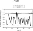
- FIG. 11 is a diagram illustrating time variations in the current spectral intensity at the specific frequency F of 99 Hz when the pressure loss in the flow path 71 is large.
- the control device 50 evaluates time variations in the current spectrum intensity at a specific frequency F of 99 Hz. As the state of clogging or the like worsens, the variation range of the current spectrum intensity in a predetermined period widens. If the variation range of the current spectrum intensity in the predetermined period is smaller than the predetermined variation range (predetermined threshold) ( FIG. 10 ), the control device 50 determines that the state of clogging or the like has not occurred. On the other hand, if the variation range of the current spectrum intensity in the predetermined period is larger than the predetermined variation range (predetermined threshold) ( FIG. 11 ), the control device 50 determines that the state of clogging or the like has occurred.
- FIG. 12 is a diagram for explaining a second detection method of the state of clogging or the like when the fan 6 is small.
- FIG. 13 is a diagram for explaining a second detection method of a state of clogging or the like when the fan 6 is large.
- the rotation speed of the fan 6 is constant (specifically, when the fan 6 is rotating at a constant instructed rotation speed,)
- the current spectrum intensity of only the rotational frequency (101 Hz for FIG. 12 ; in FIG. 13 , 126 Hz) of the fan 6 should increase.
- the rotation speed of the fan 6 is fluctuating due to a disturbance of the fluid caused by a change in the pressure loss in the flow path 71, a difference occurs in the current spectrum intensity at a specific frequency (99 Hz for FIG.
- the fluid transfer apparatus may be applied to a fluid cooling apparatus for cooling a liquid different from oil.
- the fluid cooling apparatus of the second embodiment may have the same configuration and effect as the oil cooling apparatus 10 of the first embodiment. A description of the same configuration and effect as the oil cooling apparatus 10 of the first embodiment will be omitted by referring to the above description.
- the fluid cooling apparatus of the second embodiment is, for example, an apparatus for cooling the cutting fluid of the machine tool 100.
- the fluid cooling apparatus is a kind of refrigeration apparatus for cooling a fluid.
- the state determination of the structure in the third embodiment may be a clogging determination of the heat exchanger or a clogging determination of a filter for preventing clogging of heat exchange.
- the clogging determination of the heat exchanger may be performed when frost builds up on the evaporator.
- the gas cooling apparatus is a kind of refrigeration apparatus for cooling a fluid.
- the flow path through which the fluid flows is not limited to a flow path inside the housing, as long as the flow path is partitioned by a partition, but may be a flow path inside a member different from the housing, for example, a flow path (hollow portion) inside a tube such as a duct.
- the fluid transferred along the flow path may be a gas other than air, or a liquid such as water or oil, for example. That is, the fluid transfer apparatus may be an apparatus transferring a gas other than air, or a liquid such as water or oil, for example, as long as the fluid is transferred along the flow path by the rotation of a fan.
- the structure provided in the flow path is not limited to a filter or a condenser, and may be other structures such as an evaporator.
- a detecting unit such as the control device 50 detects the state of the air A or the state of the structure through which the air A passes by monitoring a phenomenon correlated with the variation of the force F caused by the disturbance of the air A.
- the detecting unit detects a quantity correlated with the magnitude of the pressure loss generated in the flow path as the state of the air A to be detected by monitoring the phenomenon, and may detect a failure of the fan 6 such as breakage of the blade 8 based on the quantity.
- the detecting unit detects a quantity correlated with the magnitude of the pressure loss generated in the flow path, and may perform air volume control, pressure control, or rotation speed control based on the PQ characteristic (P: static pressure, Q: flow rate) of the fan without using an air volume sensor or a pressure sensor based on the quantity.
- PQ characteristic P: static pressure, Q: flow rate
Landscapes
- Engineering & Computer Science (AREA)
- Mechanical Engineering (AREA)
- General Engineering & Computer Science (AREA)
- Physics & Mathematics (AREA)
- Thermal Sciences (AREA)
- Control Of Positive-Displacement Air Blowers (AREA)
- Air Conditioning Control Device (AREA)
- Filtering Of Dispersed Particles In Gases (AREA)
Abstract
Description
- The present disclosure relates to a fluid transfer apparatus, a fluid cooling apparatus and a refrigeration apparatus, and a state detecting method of the fluid transfer apparatus.
- Conventionally, there has been known a clogging detection device that stores the number of rotations of a motor that drives a fan, and determines that the filter is clogged when the average value Nave of n rotations exceeds the reference number of rotations N1. By obtaining the average value Nave of n rotations, it is possible to reduce the influence of temperature variation of the atmosphere and power supply voltage variation (for example, see
Patent Document 1.). - [Patent Document 1]
Japanese Unexamined Patent Application Publication No. H11-290630 - However, when the average value of the number of rotations in a fixed time is determined, the variation of the number of rotations caused by the occurrence of clogging itself excluding the influence of the temperature variation of the atmosphere and the power supply voltage variation is also averaged, and the accuracy of the state detection may be degraded.
- The present disclosure provides a fluid transfer apparatus, a fluid cooling apparatus, a refrigeration apparatus, and a state detection method of the fluid transfer apparatus, which can highly accurately detect the state of a fluid transferred by a fan along a flow path or the state of a structure through which the fluid passes.
- According to a first aspect of the present disclosure, there is provided
a fluid transfer apparatus including: - a fan configured to transfer fluid along a flow path by a rotational motion;
- a structure provided in the flow path, the structure being configured to generate a pressure loss in the flow path as the fluid passes through the structure; and
- a detecting unit configured to detect a state of the fluid or a state of the structure by monitoring a phenomenon correlated with a change in a force received by a blade of the fan from the fluid due to a disturbance of the fluid transferred along the flow path by the fan.
- According to this, the state of the fluid or the state of the structure can be detected with high accuracy while reducing the influence of a temperature variation of an atmosphere and a power supply voltage variation.
- According to a second aspect, in the fluid transfer apparatus according to the first aspect, the state of the fluid detected by the detecting unit may include an amount correlated with a magnitude of the pressure loss generated in the flow path.
- According to this, the amount correlated with the magnitude of the pressure loss generated in the flow path can be detected with high accuracy.
- According to a third aspect, in the fluid transfer apparatus according to the first or second aspect, the state of the structure detected by the detecting unit may include clogging of the structure.
- According to this, clogging of the structure can be detected with high accuracy.
- According to a fourth aspect, in the fluid transfer apparatus according to any one of the first to third aspects, the phenomenon may be a change in a current, a voltage, or a power of a motor driving the fan.
- Because the change in the current, voltage, or power of the motor driving the fan is a phenomenon having a high correlation with the variation in the force caused by the disturbance, the state of the fluid or the state of the structure can be detected with high accuracy by monitoring the change in the current, voltage, or power of the motor driving the fan.
- According to a fifth aspect, in the fluid transfer apparatus according to any one of the first to third aspects, the phenomenon may be a change in a rotation speed of the fan.
- Because the change in the rotation speed of the fan is a phenomenon having a high correlation with the variation in the force caused by the disturbance, the state of the fluid or the state of the structure can be detected with high accuracy by monitoring the change in the rotation speed of the fan.
- According to a sixth aspect, in the fluid transfer apparatus according to any one of the first to third aspects, the phenomenon may be a change in sound or vibration caused by the rotational motion of the fan.
- Because the change in the sound or the vibration caused by the rotational motion of the fan is a phenomenon having high correlation with the variation in the force caused by the disturbance, the state of the fluid or the state of the structure can be detected with high accuracy by monitoring the change in the sound or the vibration caused by the rotational motion of the fan.
- According to a seventh aspect, in the fluid transfer apparatus of the fourth aspect, the phenomenon may be a change in a frequency spectrum of the current, the voltage, or the power of the motor driving the fan.
- Because the change in the frequency spectrum of the current, voltage, or power of the motor driving the fan is a phenomenon having high correlation with the variation in the force caused by the disturbance, the state of the fluid or the state of the structure can be detected with high accuracy by monitoring the change in the frequency spectrum.
- According to an eighth aspect, in the fluid transfer apparatus of the seventh aspect, the change in the frequency spectrum may be a change associated with a change in a frequency of a highest spectral intensity.
- A change in the frequency spectrum when a phenomenon occurs in which a frequency having the largest spectral intensity fluctuates is a phenomenon having a high correlation with a variation in the force caused by the disturbance. Therefore, by monitoring a change in the frequency spectrum when a phenomenon occurs in which a frequency having the largest spectral intensity fluctuates, the state of the fluid or the state of the structure can be detected with high accuracy.
- According to the ninth aspect, in the fluid transfer apparatus according to the seventh or eighth aspect, the change in the frequency spectrum may be a change in a spectral intensity of the current at a specific frequency within a machine angular frequency of the motor × N (N being a natural number) ±a (a < the machine angular frequency/20).
- The change in the spectral intensity of the current at a specific frequency within the machine angular frequency of the motor × N (N is a natural number) ±a (a < the machine angular frequency/20) is a phenomenon having a high correlation with the variation of the force caused by the disturbance. Therefore, by monitoring the change in the spectral intensity of the current at the specific frequency, the state of the fluid or the state of the structure can be detected with high accuracy.
- According to a tenth aspect, in the fluid transfer apparatus according to the ninth aspect, the current may be a direct current amount correlated with a torque of the motor.
- According to this, the state of the fluid or the state of the structure can be detected with high accuracy by monitoring a change in the spectral intensity of the DC amount at the specific frequency.
- According to an eleventh aspect, in the fluid transfer apparatus according to the seventh or eighth aspect, the current is a direct current amount correlated with a torque of the motor, and
the change in the frequency spectrum may be a change in a spectral intensity of the current at a specific frequency within a machine angular frequency of the motor × a number of blades of the fan × N (N being a natural number) ±a (a < the machine angular frequency/20). - The change in the spectral intensity of the current at a specific frequency within the range of the machine angular frequency of the motor × the number of blades of the fan × N (N is a natural number) ±a (a < the machine angular frequency/20) is a phenomenon highly correlated with the change in the force due to the disturbance. Therefore, the state of the fluid or the state of the structure can be detected with high accuracy by monitoring a change in the spectral intensity of the current at the specific frequency.
- According to a twelfth aspect of the present disclosure, there is provided
a fluid transfer apparatus including: - a fan configured to transfer fluid along a flow path by a rotational motion;
- a structure provided in the flow path, the structure being configured to generate a pressure loss in the flow path as the fluid passes through the structure; and
- a detecting unit configured to detect a state of the fluid or a state of the structure by monitoring a change in a frequency spectrum of a current, a voltage, or a power of a motor driving the fan, the change being a change in the frequency spectrum associated with a change in a frequency of a highest spectral intensity.
- According to this, the state of the fluid or the state of the structure can be detected with high accuracy.
- According to a thirteenth aspect, in the fluid transfer apparatus according to the twelfth aspect, the change in the frequency spectrum may be a change in a spectral intensity of the current at a specific frequency within a machine angular frequency of the motor × N (N being a natural number) ±a (a < the machine angular frequency/20).
- The change in the spectral intensity of the current at a specific frequency within the machine angular frequency of the motor ×N (N is a natural number) ±a (a < the machine angular frequency/20) is a phenomenon highly correlated with the variation of the force caused by the disturbance. Therefore, by monitoring the change in the spectral intensity of the current at the specific frequency, the state of the fluid or the state of the structure can be detected with high accuracy.
- According to the fourteenth aspect, in the fluid transfer apparatus according to the thirteenth aspect, the current may be a direct current amount correlated with a torque of the motor.
- According to this, by monitoring the change in the spectral intensity of the DC amount at the specific frequency, the state of the fluid or the state of the structure can be detected with high accuracy.
- According to the fifteenth aspect, in the fluid transfer apparatus according to the twelfth aspect,
- the current is a direct current amount correlated with a torque of the motor, and
- the change in the frequency spectrum may be a change in a spectral intensity of the current at a specific frequency within a machine angular frequency of the motor × a number of blades of the fan × N (N being a natural number) ±a (a < the machine angular frequency/20).
- The change in the spectral intensity of the current at a specific frequency within the range of the machine angular frequency of the motor × the number of blades of the fan ×N (N is a natural number) ±a (a < the machine angular frequency/20) is a phenomenon highly correlated with the variation of the force due to the disturbance. Therefore, the state of the fluid or the state of the structure can be detected with high accuracy by monitoring the change in the spectral intensity of the current at the specific frequency.
- According to a sixteenth aspect of the present disclosure, there is provided
a fluid transfer apparatus including: - a fan configured to transfer fluid along a flow path by a rotational motion;
- a structure provided in the flow path, the structure being configured to generate a pressure loss in the flow path as the fluid passes through the structure; and
- a detecting unit configured to detect a state of the fluid or a state of the structure based on a magnitude of pulsation of a rotation speed of the fan.
- According to this, the state of the fluid or the state of the structure can be detected with high accuracy.
- According to a seventeenth aspect of the present disclosure, there is provided a refrigeration apparatus including the fluid transfer apparatus according to any one of the first to sixteenth aspects.
- According to this, it is possible to provide a refrigeration apparatus including a fluid transfer apparatus capable of detecting the state of the fluid or the state of the structure with high accuracy.
- According to an eighteenth aspect of the present disclosure, there is provided a fluid cooling apparatus including the fluid transfer apparatus according to any one of the first to sixteenth aspects.
- According to this, it is possible to provide a fluid cooling apparatus including the fluid transfer apparatus capable of detecting the state of the fluid or the state of the structure with high accuracy.
- According to a nineteenth aspect of the present disclosure, there is provided
a method of detecting a state of a fluid transfer apparatus, the fluid transfer apparatus including: - a fan configured to transfer fluid along a flow path by a rotational motion; and
- a structure provided in the flow path, the structure being configured to generate a pressure loss in the flow path as the fluid passes through the structure, the method including:
detecting a state of the fluid or a state of the structure by monitoring a phenomenon correlated with a change in a force received by a blade of the fan from the fluid due to a disturbance of the fluid transferred along the flow path by the fan. - According to the method, the state of the fluid or the state of the structure can be detected with high accuracy.
-
- [
FIG. 1] FIG. 1 is a schematic structural view of an oil cooling apparatus according to a first embodiment. - [
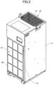
FIG. 2] FIG. 2 is a perspective view of an oil cooling apparatus according to the first embodiment. - [
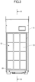
FIG. 3] FIG. 3 is a front view of an oil cooling apparatus according to the first embodiment. - [
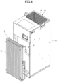
FIG. 4] FIG. 4 is a perspective view illustrating the configuration of a condenser of an oil cooling apparatus according to the first embodiment. - [
FIG. 5] FIG. 5 is a partial cross-sectional view schematically illustrating the longitudinal cross-section B-B ofFIG. 3 . - [
FIG. 6] FIG. 6 is a correlation block diagram illustrating the effects of the occurrence of a state of clogging or the like. - [
FIG. 7] FIG. 7 is a diagram for explaining a first detection method of a state of clogging or the like. - [
FIG. 8] FIG. 8 is a diagram illustrating the time variation of the frequency at which the spectral intensity is greatest. - [
FIG. 9] FIG. 9 illustrates the time variation in spectral intensity at a specific frequency. - [
FIG. 10] FIG. 10 illustrates the time variation in the current spectral intensity at a specific frequency when the pressure loss is small. - [
FIG. 11] FIG. 11 illustrates the time variation in current spectral intensity at a specific frequency when the pressure loss is large. - [
FIG. 12] FIG. 12 illustrates a second method of detecting a state of clogging or the like when the fan is small. - [
FIG. 13] FIG. 13 illustrates a second method of detecting a state of clogging or the like when the fan is large. - Embodiments will be described below. In the drawings, the same reference numerals represent the same or equivalent portions. Dimensions in the drawings, such as length, width, thickness, and depth, may not represent actual relative dimensions because they are appropriately changed from actual scales for the sake of clarity and simplification of the drawings.
-
FIG. 1 is a schematic configuration diagram of an oil cooling apparatus according to the first embodiment. Anoil cooling apparatus 10 illustrated inFIG. 1 is an example of a fluid cooling apparatus for cooling a fluid, and in this example, theoil cooling apparatus 10 cools oil. Theoil cooling apparatus 10 illustrated inFIG. 1 cools the operating oil, the lubricating oil, or the cooling oil (hereinafter, also referred to simply as "oil") of themachine tool 100 while circulating the oil through the oil tank T. Specific examples of themachine tool 100 include a machining center, an NC (Numerical Control) lathe, a grinding machine, an exclusive-use NC machine, and an NC electric discharge machine. Theoil cooling apparatus 10 may be an apparatus for cooling oil of a machine (a molding machine, a press machine, etc.) different from the machine tool. - The
oil cooling apparatus 10 includes a refrigerant circuit RC in which acompressor 1, acondenser 3, an electronic expansion valve EV, and anevaporator 4 are annularly connected, a four-way selector valve 2 for switching the refrigerant circulation direction of the refrigerant circuit RC from a positive cycle to a reverse cycle, afan 6 for supplying air to thecondenser 3, and acontrol device 50 for controlling the refrigerant circuit RC and the four-way selector valve 2. Thecontrol device 50 controls thefan 6, and more specifically, controls amotor 7 for rotating thefan 6. The electronic expansion valve EV is an example of a pressure reducing mechanism. The refrigerant circuit RC has a hot gas bypass pipe L10 and a hot gas bypass valve HGB arranged in the hot gas bypass pipe L10. - Although the embodiment illustrated here is an oil cooling apparatus capable of switching between a normal cycle and a reverse cycle by a four-way selector valve, the cooling cycle of the oil cooling apparatus may be a cycle without a four-way selector valve.
- The refrigerant circuit RC, the four-
way selector valve 2, thefan 6, and thecontrol device 50 are housed in ahousing 11. - The discharge side of the
compressor 1 is connected to thefirst port 2a of a four-way selector valve 2. Asecond port 2b of the four-way selector valve 2 is connected to one end of thecondenser 3 through a closing valve V1. The other end of thecondenser 3 is connected to one end of the electronic expansion valve EV through a closing valve V2. - The other end of the electronic expansion valve EV is connected to one
end 4a of theevaporator 4. Anotherend 4b of theevaporator 4 is connected to athird port 2c of the four-way selector valve 2. Afourth port 2d of the four-way selector valve 2 is connected to an intake side of thecompressor 1 via anaccumulator 5. The oneend 4a of theevaporator 4 is connected to one end of a hot gas bypass pipe L10. The other end of the hot gas bypass pipe L10 is connected to thesecond port 2b of the four-way selector valve 2. - The other end of the pipe L1, one end of which is immersed in oil in the oil tank T, is connected to the intake port of the circulation pump P. The discharge port of the circulation pump P is connected to the
inflow port 4c of theevaporator 4 via the pipe L2. - The
outflow port 4d of theevaporator 4 is connected to one end of the pipe L3, and the other end of the pipe L3 is connected to theinflow port 101 of themachine tool 100. Theoutflow port 102 of themachine tool 100 is connected to the oil tank T through the pipe L4. - The oil tank T, the
evaporator 4, themachine tool 100, and the pipes L1 to L4 are included in a circulation path through which oil circulates. - The oil cooling system includes an
oil cooling apparatus 10 and a circulation path. In the first embodiment, theoil cooling apparatus 10 includes a circulation pump P, but the oil cooling system may include a circulation pump outside the oil cooling apparatus. - In the oil cooling operation of the
oil cooling apparatus 10, the high-pressure gas refrigerant discharged from thecompressor 1 flows into thecondenser 3 through the four-way selector valve 2, and is then heat-exchanged with outside air in thecondenser 3 to be condensed to become a liquid refrigerant. Next, the liquid refrigerant reduced in pressure in the electronic expansion valve EV flows into theevaporator 4, and is then heat-exchanged with oil and evaporated to become a low-pressure gas refrigerant, and returns to the intake side of thecompressor 1 through theaccumulator 5. Thus, the oil is cooled in theevaporator 4. In this oil cooling operation, thecontrol device 50 controls the rotational frequency of thecompressor 1 and the opening degree of the electronic expansion valve EV based on the temperature of the oil and the room temperature. The hot gas bypass valve HGB arranged in the hot gas bypass pipe L10 controls the cooling capability at a low load by adjusting the amount of high-temperature and high-pressure gas supplied to theevaporator 4. -
FIG. 2 is a perspective view of theoil cooling apparatus 10, andFIG. 3 is a front view of theoil cooling apparatus 10. In the example illustrated inFIGS. 2 and3 , theoil cooling apparatus 10 includes the longitudinalrectangular parallelepiped housing 11. In this example, theintake port 12 located upstream of thecondenser 3 is provided on one side surface (front surface) of thehousing 11, and ablowout port 14 located downstream of thecondenser 3 is provided on the top surface side of thehousing 11. The positions of theintake port 12 and theblowout port 14 are not limited to the above. - A
filter 13 is attached to theintake port 12. Thefilter 13 is fixed to thehousing 11 by a mountingframe 20. - The
filter 13 has a filter material formed of, for example, a nonwoven fabric. The shape of the filter material may be flat, pleated, net-like, or roll-like, but is not limited thereto. -
FIG. 4 illustrates a state in which thecondenser 3 is removed from thehousing 11. Thecondenser 3 has a plurality of plate-like fins 3a arranged parallel to each other and along the vertical direction. -
FIG. 5 is a partial cross-sectional view schematically illustrating the longitudinal cross-section B-B ofFIG. 3 . Thefilter 13, thecondenser 3, and thefan 6 are arranged in thehousing 11 in the order of thefilter 13, thecondenser 3, and thefan 6 from theintake port 12 side. Thefilter 13 may be attached to theintake port 12 of thehousing 11 with an interval D (for example, 10 mm) with respect to thecondenser 3, or may be partially or entirely in contact with the condenser 3 (interval D=0 mm). - In the
oil cooling apparatus 10, outside air is taken in from theintake port 12 through thefilter 13 by rotation of thefan 6, supplied to thecondenser 3, and then discharged from theblowout port 14. - Depending on the environment in which the
oil cooling apparatus 10 is used, air A containing foreign matter such as oil smoke (oil mist) and dust generated by themachine tool 100 may be supplied to thefilter 13 or thecondenser 3. When air A containing foreign matter is supplied to thefilter 13 or thecondenser 3, clogging of thefilter 13 or thecondenser 3 occurs. When clogging occurs, the ability of theoil cooling apparatus 10 to cool oil decreases, which may result in, for example, themachine tool 100 suddenly stopping or decreased processing accuracy. When clogging occurs in thecondenser 3, it is necessary to remove thecondenser 3 from thehousing 11 and perform measures such as cleaning and replacement, resulting in a long down time and a large opportunity loss. - The
oil cooling apparatus 10 according to the first embodiment of the present disclosure includes afluid transfer apparatus 70 having a function of detecting clogging of thefilter 13 or thecondenser 3. Thefluid transfer apparatus 70 is an apparatus for transferring air A, which is an example of fluid, from theintake port 12 to theblowout port 14. Thefluid transfer apparatus 70 includes afan 6, amotor 7, afilter 13, acondenser 3, acontrol device 50, and anoutput device 60. - The
fan 6 is an example of a rotating body for transferring air A along theflow path 71 in thehousing 11 by rotary driving by themotor 7. In this example, thefan 6 is arranged at a position somewhere along theflow path 71, but may be arranged at an end (e.g., blowout port 14) of theflow path 71. Air A flowing in theflow path 71 is transferred from theintake port 12 to theblowout port 14 by rotation of thefan 6. Thefan 6 rotates so that air A is taken in from theintake port 12 through thefilter 13, and air A filtered through thefilter 13 is supplied to thecondenser 3. Air A passing through thecondenser 3 is discharged from theblowout port 14 by rotation of thefan 6. Thefan 6 has a plurality ofblades 8 rotated by driving of themotor 7. Thefan 6 is, for example, an axial flow fan such as a propeller fan. - The
flow path 71 is a passage through which air A flows. At least a part of theflow path 71 may be formed by a structure such as a duct arranged in thehousing 11, may be formed by aninner wall 72 in thehousing 11, or may be formed by ahousing 11. In the example illustrated inFIG. 1 , theflow path 71 is an internal space surrounded by aninner wall 72 in thehousing 11, aninner surface 11a of thehousing 11, and anoil reservoir 33. - The
housing 11 has, for example, abottom frame 30 that covers the lower side of thehousing 11. Thebottom frame 30 has anoil reservoir 33 provided below thecondenser 3 and thefilter 13. Theoil reservoir 33 receives and stores oil droplets from thecondenser 3 and thefilter 13. Theoil reservoir 33 is also referred to as an oil pan. Theoil reservoir 33 may be formed integrally with thebottom frame 30 or may be provided separately from thebottom frame 30. - The
motor 7 is an electric motor for rotating thefan 6. The rotating shaft of themotor 7 is connected directly or via a gear to the center of rotation of thefan 6. Themotor 7 is controlled by thecontrol device 50. Themotor 7 may be arranged in theflow path 71 or outside theflow path 71. By arranging themotor 7 in theflow path 71, themotor 7 can be cooled by air A. - The
filter 13 is an example of a structure provided in theflow path 71 and having a path through which air A passes. Thefilter 13 is a structure through which air A passes and filters the air A. Thefilter 13 may be provided at an end (for example, the open end of theflow path 71, more specifically, the intake port 12) of theflow path 71 or in the middle (e.g., within the duct forming the flow path 71) of theflow path 71. For example, when thefilter 13 is made of a nonwoven fabric, the gap between the fibers of the nonwoven fabric corresponds to a passage through which air A passes. - The
condenser 3 is an example of a structure provided in theflow path 71 and having a passage through which air A passes. Thecondenser 3 is a structure through which air A passes, and is provided at a position somewhere along theflow path 71. Thecondenser 3 is a heat exchanger that liquefies a high-pressure, high-temperature gas refrigerant by exchanging heat with air A. In the illustrated example, thecondenser 3 is arranged between thefilter 13 and thefan 6. The gap between the plurality of fins 3a arranged as illustrated inFIG. 4 corresponds to a passage through which air A passes. - In
FIG. 5 , thecontrol device 50 has a drivingcircuit 51 that drives themotor 7 by switching a plurality of semiconductor switching elements. The drivingcircuit 51 supplies a drive current to themotor 7, and themotor 7 rotates thefan 6 when the drive current is supplied from the drivingcircuit 51. The drivingcircuit 51 is, for example, an inverter circuit that converts a direct current from a direct current source into an alternating current that is supplied to themotor 7. - The heat of the driving
circuit 51 is transferred to theheat sink 52. Because theheat sink 52 is arranged in theflow path 71, theheat sink 52 is cooled by the air A, and the heat dissipation effect of theheat sink 52 on the drivingcircuit 51 is improved. In the illustrated example, thecontrol device 50 is separated from theflow path 71 by theinner wall 72, but thecontrol device 50 may be arranged in theflow path 71. The drivingcircuit 51 may be arranged at a different location from thecontrol device 50. - The
filter 13 is a structure that generates a pressure loss in theflow path 71 when the air A passes through thefilter 13. Similarly, thecondenser 3 is a structure that generates a pressure loss in theflow path 71 when the air A passes through thecondenser 3. - When the
control device 50 controls the rotation speed of thefan 6 or themotor 7 to be constant, the average rotation speed of thefan 6 becomes constant, although the rotation speed of thefan 6 fluctuates slightly. On the other hand, as the clogging of thefilter 13 or thecondenser 3 worsens, the pressure loss in theflow path 71 increases. When the pressure loss in theflow path 71 increases, the degree of disturbance of the air A transferred by thefan 6 along theflow path 71 increases. The disturbance refers to a state in which the flow direction of the fluid, the flow velocity of the fluid, or the pressure of the fluid fluctuates irregularly. The flow direction of the fluid and the flow velocity of the fluid can be measured by using, for example, a flow velocity sensor (electromagnetic type, ultrasonic type, Karman vortex type, thermal type, etc.) or the like, or particle image velocimetry (PIV). The pressure of the fluid can be measured by using, for example, a strain gauge sensor or the like. When thecontrol device 50 controls the rotation speed of thefan 6 or themotor 7 to be constant in a state in which the air A is disturbed, the average rotation speed of thefan 6 does not appreciably change. However, the variation of the load on thefan 6 changes due to the disturbance whose degree is increased by the increase of the pressure loss due to clogging, resulting in an increase in the degree of variation of the rotation speed of thefan 6. -
FIG. 6 is a correlation block diagram illustrating the influence of a state of clogging or the like. When a state of clogging or the like occurs in thefilter 13 or thecondenser 3, the degree of turbulence (disturbance) of the air A in theflow path 71 increases. When theblades 8 of thefan 6 are disturbed by the air A, the variation of the force F applied to the blades 8 (variation of the load applied to the fan 6) is disturbed. The variation of the load variation of thefan 6 increases the variation of the rotation speed of thefan 6, although the average rotation speed of thefan 6 is constant. When the variation of the rotation speed of thefan 6 increases, the variation of the phase current flowing through themotor 7 that drives thefan 6 also increases. - Thus, when the state of the air A transferred by the
fan 6 along theflow path 71 or the state of the structure through which the air A passes significantly changes, the degree of disturbance of the air A transferred by thefan 6 along theflow path 71 increases. The force F exerted on theblade 8 of thefan 6 by the air A fluctuates due to the disturbance of the air A. - By focusing on this correlation, the
control device 50 illustrated inFIG. 5 functions as a detecting unit that monitors a phenomenon correlated with the variation of the force F due to the disturbance of the air A and detects, for example, the state of the air A or the state of the structure through which the air A passes. The variation of the force F due to the disturbance of the air A means a state in which the variation of the force F increases due to the disturbance of the air A. Because thecontrol device 50 has such a function as a detecting unit, it is possible to detect the state of the fluid such as the disturbance of the air A or the state of the structure such as the clogging of thefilter 13 or thecondenser 3 with high accuracy by monitoring the phenomenon correlated with the variation of the force F caused by the disturbance of the air A. - As the phenomenon correlated with the variation of the force F caused by the disturbance of the air A, there is a change in the current, voltage, or power of the
motor 7 which drives thefan 6. Thecontrol device 50 may detect the state of the fluid such as the disturbance of the air A or the state of the structure such as the clogging of thefilter 13 or thecondenser 3 by monitoring, for example, the change in the phase current flowing through themotor 7 with the current sensor. Thecontrol device 50 may detect the state of the fluid such as the disturbance of the air A or the state of the structure such as the clogging of thefilter 13 or thecondenser 3 by monitoring, for example, the change in the voltage generated in themotor 7 with the voltage sensor. Thecontrol device 50 may detect the state of the fluid such as the disturbance of the air A or the state of the structure such as the clogging of thefilter 13 or thecondenser 3 by monitoring, for example, the change in the power input/output to themotor 7 with the current sensor and the voltage sensor. Because the current sensor and the voltage sensor for detecting the current, voltage, and power of themotor 7 are already provided for fan control, it is not necessary to separately provide the aforementioned flow velocity sensor or the like in order to detect the disturbance of the air A, so that there is no need for additional cost for implementing this configuration. - As a phenomenon correlated with the change in the force F caused by the disturbance of the air A, there is a change in the rotation speed of the
fan 6. Thecontrol device 50 may detect the state of the fluid such as the disturbance of the air A or the state of the structure such as the clogging of thefilter 13 or thecondenser 3 by monitoring, for example, the change in the rotation speed of the fan 6 (more specifically, the magnitude of the pulsation of the rotation speed of the fan 6) with the sensor. - As a phenomenon correlated with the variation of the force F caused by the disturbance of the air A, there is a change in sound or vibration generated by the rotational motion of the
fan 6. Thecontrol device 50 may detect, for example, the state of a fluid such as the disturbance of the air A or the state of a structure such as the clogging of thefilter 13 or thecondenser 3 by monitoring the change in sound or vibration generated by the rotational motion of thefan 6 with a sensor. - As described above, when the magnitude of the pressure loss generated in the
flow path 71 changes, the degree of the disturbance of the air A increases and the variation of the force F increases. By focusing on this feature, thecontrol device 50 may detect a quantity correlated with the magnitude of the pressure loss generated in theflow path 71 by monitoring the phenomenon correlated with the variation of the force F caused by the disturbance of the air A. - The
control device 50 is a control unit including, for example, a processor such as a CPU (Central Processing Unit) and a memory. The function of thecontrol device 50 is implemented by causing the processor to operate by a program stored in the memory. The function of thecontrol device 50 may be implemented by an FPGA (Field Programmable Gate Array) or an ASIC (Application Specific Integrated Circuit). - The
output device 60 is an example of an output unit for outputting detection information indicating the state of the air A detected by thecontrol device 50 or the state of the structure through which the air A passes. Theoutput device 60 outputs detection information to the outside of thefluid transfer apparatus 70 by, for example, sound, light, display, communication, or any combination thereof. Specific examples of theoutput device 60 include a speaker, a lamp, a display, a communication device, or a combination thereof. - Thus, according to the
fluid transfer apparatus 70, theoutput device 60 outputs detection information when the state of the air A detected by thecontrol device 50 or the state of the structure through which the air A passes satisfies a predetermined condition. Because the detection information is output by the execution of the above state detection method by thefluid transfer apparatus 70, for example, the occurrence of clogging in thefilter 13 or thecondenser 3 can be detected. - Because clogging in the
filter 13 or thecondenser 3 can be detected, for example, maintenance work of thefilter 13 or thecondenser 3 can be facilitated, and an increase in hours labored and costs for management and maintenance can be prevented. Further, because clogging in thefilter 13 or thecondenser 3 can be detected, prior measures such as cleaning or replacement of thefilter 13 or thecondenser 3 can be taken before a malfunction such as a decrease in the oil cooling capability of theoil cooling apparatus 10 occurs. - The
output device 60 may report the detection information to a user or an external device. Thus, the user or the external device can recognize the clogging of thefilter 13 or thecondenser 3. -
FIG. 7 is a diagram for explaining the first detection method of the clogging. The current waveform in the upper part ofFIG. 7 represents the transition of the phase current for 3 seconds flowing through themotor 7 for rotationally driving thefan 6 in response to a predetermined rotation speed instruction. Thecontrol device 50 performs Fast Fourier Transform (FFT) on the phase current detected by the current sensor at predetermined intervals (In this example, every second). The three frequency spectra in the lower part ofFIG. 7 represent the results of FFT on the phase current at predetermined intervals. In the legend, the large pressure loss and the small pressure loss represent the pressure loss in theflow path 71. The larger the pressure loss in theflow path 71, the more severe the clogging. - As illustrated by the three frequency spectra in the lower part of
FIG. 7 , when the state of the air A transferred by thefan 6 along theflow path 71 or the state of the structure through which the air A passes significantly changes, the frequency spectrum changes in a manner corresponding to the change. Therefore, thecontrol device 50 can detect the state of the air A transferred by thefan 6 along theflow path 71 or the state of the structure through which the air A passes with high accuracy by monitoring the change in the frequency spectrum of the current, voltage, or power of themotor 7 when thefan 6 is driven. - For example, the
control device 50 may detect the state of the air A or the state of the structure through which the air A passes by monitoring the change in the spectrum when the frequency with the largest spectral intensity changes. The frequency with the largest spectral intensity may not be the frequency with the largest spectral intensity within all frequencies, but may be the frequency with the largest spectral intensity within the frequency of the machine angular frequency of themotor 7 × N±a (a < the machine angular frequency/20). For example, when the pressure loss is large due to clogging of the structure, a phenomenon P occurs in which the spectral intensity of the frequency f1 becomes largest in the frequency spectrum of the first period, the spectral intensity of the frequency (f1+a1) becomes largest in the frequency spectrum of the second period different from the first period, and the spectral intensity of the frequency (f1-a2) becomes largest in the frequency spectrum of the third period different from the first and second periods. The notations of a1 and a2 represent frequency change components. The phenomenon P is an example of a phenomenon in which the frequency with the largest spectral intensity varies. -
FIG. 8 is a diagram illustrating a time variation of the frequency (maximum intensity frequency) at which the spectral intensity becomes maximum. When clogging occurs, the pressure loss increases, and the phenomenon P occurs, the width (range R), in which the frequency at which the spectral intensity becomes maximum fluctuates, increases. - The
control device 50 can detect, for example, the state of air A or the state of a structure through which air A passes by monitoring the difference in the range R when phenomenon P occurs. Thecontrol device 50 detects that a state of clogging or the like has occurred when the range R is greater than or equal to or equal to a predetermined threshold value. On the other hand, thecontrol device 50 detects that a state of clogging or the like has not occurred when the range R is less than a predetermined threshold value. - The
control device 50 can detect, for example, the state of air A or the state of a structure through which air A passes by monitoring the difference in the extreme value of the maximum intensity frequency when phenomenon P occurs. Thecontrol device 50 detects that a state of clogging or the like has occurred when the maximum value of the maximum intensity frequency when phenomenon P occurs is greater than or equal to a predetermined first frequency fa, or when the minimum value of the maximum intensity frequency when phenomenon P occurs is less than or equal to a predetermined second frequency fb (fb<fa). On the other hand, thecontrol device 50 detects that a state of clogging or the like has not occurred when the maximum value of the maximum intensity frequency when phenomenon P occurs is less than a predetermined first frequency fa, and when the minimum value of the maximum intensity frequency when phenomenon P occurs exceeds a predetermined second frequency fb. - When the phenomenon P occurs, for example, the spectral intensity at a predetermined frequency (f1+a1) changes for each of the first to third three periods. Therefore, the
control device 50 can detect the state of the air A or the state of the structure through which the air A passes by monitoring the change (difference) of the spectral intensity at a predetermined frequency (f1+a1) when the phenomenon P occurs. - The
control device 50 may monitor the change of the spectral intensity of the phase current at a specific frequency F. The specific frequency F is set within, for example, the machine angular frequency of themotor 7 × N (N is a natural number) ±a (a < the machine angular frequency/20). In the example illustrated inFIG. 7 , the machine angular frequency of themotor 7 is f1. As illustrated in the three frequency spectra illustrated in the lower part ofFIG. 7 , the change of the spectral intensity of the phase current at the specific frequency F is larger for the frequency spectrum in which the pressure loss in theflow path 71 is larger. Thecontrol device 50 monitors the change of the spectral intensity of the phase current at the specific frequency F, and can detect the state of the air A or the state of the structure through which the air A passes according to the difference of the spectral intensity of the phase current at the specific frequency F. - The
control device 50 may monitor a change in the spectral intensity of the current vector amplitude (that is, the direct current (DC) amount D correlated with the torque of the motor 7) at a specific frequency F. The current vector amplitude is represented by the square root of the sum of squares of the phase currents of all phases flowing through themotor 7. In this case, the specific frequency F is set within, for example, the machine angular frequency of themotor 7 × the number ofblades 8 × N (N is a natural number) ± a (a < the machine angular frequency/20). Thecontrol device 50 acquires the frequency spectrum of the current vector at each predetermined period by performing the Fast Fourier Transform (FFT) of the DC amount D correlated with the torque of themotor 7 at each predetermined period. In the case of the frequency spectrum of the current vector, the peak of the spectral intensity of the current vector appears at the frequency component of (the machine angular frequency of themotor 7 × the number ofblades 8 × N). For the frequency spectrum with the greater pressure loss in theflow path 71, the change in the spectral intensity of the current vector at the specific frequency F will be greater. Thecontrol device 50 monitors the change in the current spectrum at the specific frequency F, and can detect the state of the air A or the state of the structure through which the air A passes according to the difference in the spectral intensity of the current vector at the specific frequency F. - The DC amount D correlated with the torque of the
motor 7 may be, in addition to the current vector amplitude, the square value of the current vector amplitude, the amplitude or the actual value of the phase current flowing through themotor 7, or the current obtained by converting the α-axis current and the β-axis current obtained by converting the phase current flowing through themotor 7 into three phases and two phases, into rotational coordinates by an angle based on the primary magnetic flux or the direction of the magnetic pole of the rotor of themotor 7. -
FIG. 9 is a diagram illustrating time variations in the spectral intensity at the specific frequency F. Looking at time variations in the current spectral intensity at the specific frequency F, the larger the pressure loss, the larger the change range of the current spectral intensity. When the spectral intensity at the specific frequency F fluctuates more than a predetermined variation range, thecontrol device 50 detects that a state of clogging or the like has occurred. When the spectral intensity at the specific frequency F fluctuates less than a predetermined variation range, thecontrol device 50 detects that a state of clogging or the like has not occurred. - The number of the specific frequencies F used for determining the state of clogging or the like is not limited to one, but may be plural. The frequency spectrum used by the
control device 50 for determining the state of clogging or the like is not limited to the frequency spectrum of the current of themotor 7, but may be the frequency spectrum of the voltage or power of themotor 7. -
FIG. 10 is a diagram illustrating time variations in the current spectral intensity at the specific frequency F of 99 Hz when the pressure loss in theflow path 71 is small.FIG. 11 is a diagram illustrating time variations in the current spectral intensity at the specific frequency F of 99 Hz when the pressure loss in theflow path 71 is large. - The
control device 50 evaluates time variations in the current spectrum intensity at a specific frequency F of 99 Hz. As the state of clogging or the like worsens, the variation range of the current spectrum intensity in a predetermined period widens. If the variation range of the current spectrum intensity in the predetermined period is smaller than the predetermined variation range (predetermined threshold) (FIG. 10 ), thecontrol device 50 determines that the state of clogging or the like has not occurred. On the other hand, if the variation range of the current spectrum intensity in the predetermined period is larger than the predetermined variation range (predetermined threshold) (FIG. 11 ), thecontrol device 50 determines that the state of clogging or the like has occurred. - In order to reduce the detection error of the variation range of the current spectrum intensity, one or more upper current spectra and one or more lower current spectra may be removed from the variation range of the current spectrum intensity. Further, in order to reduce the detection error of the variation range of the current spectrum intensity, the variation range of the current spectrum intensity may be measured from the effective value of the current spectrum intensity.
-
FIG. 12 is a diagram for explaining a second detection method of the state of clogging or the like when thefan 6 is small.FIG. 13 is a diagram for explaining a second detection method of a state of clogging or the like when thefan 6 is large. When the rotation speed of thefan 6 is constant (specifically, when thefan 6 is rotating at a constant instructed rotation speed,), the current spectrum intensity of only the rotational frequency (101 Hz forFIG. 12 ; inFIG. 13 , 126 Hz) of thefan 6 should increase. However, when the rotation speed of thefan 6 is fluctuating due to a disturbance of the fluid caused by a change in the pressure loss in theflow path 71, a difference occurs in the current spectrum intensity at a specific frequency (99 Hz forFIG. 12 ; inFIG. 13 , 125 Hz) different from the rotational frequency of thefan 6. When the current spectrum intensity at a specific frequency different from the rotational frequency of thefan 6 exceeds a predetermined state determination specified value, thecontrol device 50 determines that a state of clogging or the like has occurred. On the other hand, when the current spectrum intensity at a specific frequency different from the rotational frequency of thefan 6 is lower than a predetermined state determination specified value, thecontrol device 50 determines that a state of clogging or the like has not occurred. - The fluid transfer apparatus may be applied to a fluid cooling apparatus for cooling a liquid different from oil. The fluid cooling apparatus of the second embodiment may have the same configuration and effect as the
oil cooling apparatus 10 of the first embodiment. A description of the same configuration and effect as theoil cooling apparatus 10 of the first embodiment will be omitted by referring to the above description. The fluid cooling apparatus of the second embodiment is, for example, an apparatus for cooling the cutting fluid of themachine tool 100. The fluid cooling apparatus is a kind of refrigeration apparatus for cooling a fluid. - The fluid transfer apparatus may be applied to a gas cooling apparatus for cooling a gas. The gas cooling apparatus of the third embodiment may have the same configuration and effect as the
oil cooling apparatus 10 of the first embodiment. A description of the same configuration and effect as theoil cooling apparatus 10 of the first embodiment will be omitted by referring to the above description. The gas cooling apparatus of the third embodiment is, for example, an air conditioner for an air conditioning operation of at least one of cooling and heating. In this case, the heat exchanger to which the fluid is supplied may be a heat exchanger functioning as a condenser or a heat exchanger functioning as an evaporator. The state determination of the structure in the third embodiment may be a clogging determination of the heat exchanger or a clogging determination of a filter for preventing clogging of heat exchange. The clogging determination of the heat exchanger may be performed when frost builds up on the evaporator. The gas cooling apparatus is a kind of refrigeration apparatus for cooling a fluid. - Although the embodiments have been described above, it will be understood that various changes in form and details can be made without departing from the spirit and scope of the claims. Various modifications and improvements such as combination with or replacement with some or all of the other embodiments are possible.
- For example, the flow path through which the fluid flows is not limited to a flow path inside the housing, as long as the flow path is partitioned by a partition, but may be a flow path inside a member different from the housing, for example, a flow path (hollow portion) inside a tube such as a duct.
- The fluid transferred along the flow path may be a gas other than air, or a liquid such as water or oil, for example. That is, the fluid transfer apparatus may be an apparatus transferring a gas other than air, or a liquid such as water or oil, for example, as long as the fluid is transferred along the flow path by the rotation of a fan.
- The structure provided in the flow path is not limited to a filter or a condenser, and may be other structures such as an evaporator.
- A detecting unit such as the
control device 50 detects the state of the air A or the state of the structure through which the air A passes by monitoring a phenomenon correlated with the variation of the force F caused by the disturbance of the air A. The detecting unit detects a quantity correlated with the magnitude of the pressure loss generated in the flow path as the state of the air A to be detected by monitoring the phenomenon, and may detect a failure of thefan 6 such as breakage of theblade 8 based on the quantity. The detecting unit detects a quantity correlated with the magnitude of the pressure loss generated in the flow path, and may perform air volume control, pressure control, or rotation speed control based on the PQ characteristic (P: static pressure, Q: flow rate) of the fan without using an air volume sensor or a pressure sensor based on the quantity. - The present international application is based upon and claims priority to
Japanese patent application no. 2022-057307 filed on March 30, 2022 -
- 1... compressor
- 2... four-way selector valve
- 3... condenser
- 4... evaporator
- 5... accumulator
- 6... fan
- 7... motor
- 8... blade
- 10... oil cooling apparatus
- 11... housing
- 12... intake port
- 13... filter
- 14... blowout port
- 20... mounting frame
- 30... bottom frame
- 33... oil reservoir
- 50... control device
- 51... driving circuit
- 52... heat sink
- 60... output device
- 70... fluid transfer apparatus
- 71... flow path
- 72... inner wall
- 100... machine tool
- ev... electronic expansion valve
- hgb... hot gas pipe valve
- L1, L2, L3, L4... pipe
- L10... hot gas bypass pipe
- P... circulation pump
- RC... refrigerant circuit
- T... oil tank
- V1, V2... closing valve
Claims (19)
- A fluid transfer apparatus comprising:a fan configured to transfer fluid along a flow path by a rotational motion;a structure provided in the flow path, the structure being configured to generate a pressure loss in the flow path as the fluid passes through the structure; anda detecting unit configured to detect a state of the fluid or a state of the structure by monitoring a phenomenon correlated with a change in a force received by a blade of the fan from the fluid due to a disturbance of the fluid transferred along the flow path by the fan.
- The fluid transfer apparatus according to claim 1, wherein the state of the fluid detected by the detecting unit includes an amount correlated with a magnitude of the pressure loss generated in the flow path.
- The fluid transfer apparatus according to claim 1 or 2, wherein the state of the structure detected by the detecting unit includes clogging of the structure.
- The fluid transfer apparatus according to any one of claims 1 to 3, wherein the phenomenon is a change in a current, a voltage, or a power of a motor driving the fan.
- The fluid transfer apparatus according to any one of claims 1 to 3, wherein the phenomenon is a change in a rotation speed of the fan.
- The fluid transfer apparatus according to any one of claims 1 to 3, wherein the phenomenon is a change in sound or vibration caused by the rotational motion of the fan.
- The fluid transfer apparatus according to claim 4, wherein the phenomenon is a change in a frequency spectrum of the current, the voltage, or the power of the motor driving the fan.
- The fluid transfer apparatus according to claim 7, wherein the change in the frequency spectrum is a change associated with a change in a frequency of a highest spectral intensity.
- The fluid transfer apparatus according to claim 7 or 8, wherein the change in the frequency spectrum is a change in a spectral intensity of the current at a specific frequency within a machine angular frequency of the motor × N (N being a natural number) ±a (a < the machine angular frequency/20).
- The fluid transfer apparatus according to claim 9, wherein the current is a direct current amount correlated with a torque of the motor.
- The fluid transfer apparatus according to claim 7 or 8, whereinthe current is a direct current amount correlated with a torque of the motor, andthe change in the frequency spectrum is a change in a spectral intensity of the current at a specific frequency within a machine angular frequency of the motor × a number of blades of the fan × N (N being a natural number) ±a (a < the machine angular frequency/20).
- A fluid transfer apparatus comprising:a fan configured to transfer fluid along a flow path by a rotational motion;a structure provided in the flow path, the structure being configured to generate a pressure loss in the flow path as the fluid passes through the structure; anda detecting unit configured to detect a state of the fluid or a state of the structure by monitoring a change in a frequency spectrum of a current, a voltage, or a power of a motor driving the fan, the change being a change in the frequency spectrum associated with a change in a frequency of a highest spectral intensity.
- The fluid transfer apparatus according to claim 12, wherein the change in the frequency spectrum is a change in a spectral intensity of the current at a specific frequency within a machine angular frequency of the motor × N (N being a natural number) ±a (a < the machine angular frequency/20).
- The fluid transfer apparatus according to claim 13, wherein the current is a direct current amount correlated with a torque of the motor.
- The fluid transfer apparatus according to claim 12, whereinthe current is a direct current amount correlated with a torque of the motor, andthe change in the frequency spectrum is a change in a spectral intensity of the current at a specific frequency within a machine angular frequency of the motor × a number of blades of the fan × N (N being a natural number) ±a (a < the machine angular frequency/20).
- A fluid transfer apparatus comprising:a fan configured to transfer fluid along a flow path by a rotational motion;a structure provided in the flow path, the structure being configured to generate a pressure loss in the flow path as the fluid passes through the structure; anda detecting unit configured to detect a state of the fluid or a state of the structure based on a magnitude of pulsation of a rotation speed of the fan.
- A refrigeration apparatus comprising the fluid transfer apparatus according to any one of claims 1 to 16.
- A fluid cooling apparatus comprising the fluid transfer apparatus according to any one of claims 1 to 16.
- A method of detecting a state of a fluid transfer apparatus, the fluid transfer apparatus including:a fan configured to transfer fluid along a flow path by a rotational motion; anda structure provided in the flow path, the structure being configured to generate a pressure loss in the flow path as the fluid passes through the structure, the method comprising:
detecting a state of the fluid or a state of the structure by monitoring a phenomenon correlated with a change in a force received by a blade of the fan from the fluid due to a disturbance of the fluid transferred along the flow path by the fan.
Applications Claiming Priority (2)
| Application Number | Priority Date | Filing Date | Title |
|---|---|---|---|
| JP2022057307A JP7376817B2 (en) | 2022-03-30 | 2022-03-30 | Fluid transport device, liquid cooling device, refrigeration device, and state detection method of fluid transport device |
| PCT/JP2023/009993 WO2023189577A1 (en) | 2022-03-30 | 2023-03-15 | Fluid transport device, liquid cooling device, refrigeration device, and method for detecting state of fluid transport device |
Publications (2)
| Publication Number | Publication Date |
|---|---|
| EP4484755A1 true EP4484755A1 (en) | 2025-01-01 |
| EP4484755A4 EP4484755A4 (en) | 2025-06-04 |
Family
ID=88201506
Family Applications (1)
| Application Number | Title | Priority Date | Filing Date |
|---|---|---|---|
| EP23779595.0A Pending EP4484755A4 (en) | 2022-03-30 | 2023-03-15 | FLUID TRANSPORT DEVICE, LIQUID COOLING DEVICE, REFRIGERATION DEVICE, AND FLUID TRANSPORT DEVICE STATE DETECTION METHOD |
Country Status (5)
| Country | Link |
|---|---|
| US (1) | US20250012288A1 (en) |
| EP (1) | EP4484755A4 (en) |
| JP (1) | JP7376817B2 (en) |
| CN (1) | CN118974416A (en) |
| WO (1) | WO2023189577A1 (en) |
Family Cites Families (16)
| Publication number | Priority date | Publication date | Assignee | Title |
|---|---|---|---|---|
| US4751501A (en) * | 1981-10-06 | 1988-06-14 | Honeywell Inc. | Variable air volume clogged filter detector |
| JPH0576713A (en) * | 1991-09-26 | 1993-03-30 | Matsushita Electric Ind Co Ltd | Air cleaner |
| JPH05223312A (en) * | 1991-12-18 | 1993-08-31 | Mitsubishi Electric Corp | Device for detecting clogging of filter of air conditioner |
| JPH05332590A (en) * | 1992-05-29 | 1993-12-14 | Hitachi Ltd | Air conditioner |
| JPH0680019A (en) * | 1992-09-02 | 1994-03-22 | Mitsubishi Motors Corp | Vehicle air purification device |
| JPH08285348A (en) * | 1995-04-18 | 1996-11-01 | Mitsubishi Heavy Ind Ltd | Air conditioner |
| JP4209493B2 (en) | 1998-04-15 | 2009-01-14 | パナソニックエコシステムズ株式会社 | How to detect filter clogging |
| JP3951934B2 (en) * | 2003-02-24 | 2007-08-01 | トヨタ自動車株式会社 | Electric motor system, motor system abnormality detection device and abnormality detection method |
| JP2004325017A (en) | 2003-04-28 | 2004-11-18 | Hitachi Ltd | Air conditioner |
| JP4374965B2 (en) * | 2003-09-29 | 2009-12-02 | パナソニック株式会社 | Ventilation device |
| US20060204383A1 (en) * | 2005-03-08 | 2006-09-14 | Hiroyuki Kushida | Electric vacuum cleaner |
| JP2010091230A (en) | 2008-10-10 | 2010-04-22 | Panasonic Corp | Ventilation device |
| US7941294B2 (en) * | 2009-02-10 | 2011-05-10 | Emerson Electric Co. | System and method for detecting fluid delivery system conditions based on motor parameters |
| US9732976B2 (en) * | 2014-01-28 | 2017-08-15 | Zhongshan Broad-Ocean Motor Co., Ltd. | Direct power control for constant airflow control with advanced motor system modeling |
| WO2019187003A1 (en) * | 2018-03-30 | 2019-10-03 | 日本電気株式会社 | State estimation device, method, and program recording medium |
| JP7609595B2 (en) | 2020-09-30 | 2025-01-07 | 花王株式会社 | Ammonia metabolism promoter |
-
2022
- 2022-03-30 JP JP2022057307A patent/JP7376817B2/en active Active
-
2023
- 2023-03-15 EP EP23779595.0A patent/EP4484755A4/en active Pending
- 2023-03-15 CN CN202380029897.8A patent/CN118974416A/en active Pending
- 2023-03-15 WO PCT/JP2023/009993 patent/WO2023189577A1/en not_active Ceased
-
2024
- 2024-09-24 US US18/894,431 patent/US20250012288A1/en active Pending
Also Published As
| Publication number | Publication date |
|---|---|
| WO2023189577A1 (en) | 2023-10-05 |
| US20250012288A1 (en) | 2025-01-09 |
| CN118974416A (en) | 2024-11-15 |
| JP2023148997A (en) | 2023-10-13 |
| JP7376817B2 (en) | 2023-11-09 |
| EP4484755A4 (en) | 2025-06-04 |
Similar Documents
| Publication | Publication Date | Title |
|---|---|---|
| JP5268317B2 (en) | Oil-cooled air compressor | |
| EP3356680B1 (en) | Centrifugal compressor with magnetic bearings and surge prediction using a shaft position | |
| KR101723385B1 (en) | Motor housing temperature control system | |
| KR101498689B1 (en) | Hermetic motor cooling and control | |
| EP3037745A1 (en) | Heat source device and method for controlling same | |
| CN102384855A (en) | Performance evaluation device for centrifugal chiller | |
| KR102297053B1 (en) | Method for protecting an electric motor of a device with a motor driven consumer having a continuous capacity control system and selection of such a motor | |
| JP2014199053A (en) | Thermal/noise management in scroll pump | |
| US9677566B2 (en) | Centrifugal compressor inlet guide vane control | |
| US20250012288A1 (en) | Fluid transfer apparatus, fluid cooling apparatus and refrigeration apparatus, as well as method of detecting state of fluid transfer apparatus | |
| CN115523178A (en) | Surge prevention in a refrigerating machine with a centrifugal compressor | |
| CN111954762A (en) | Method for controlling at least one radial fan in a refrigeration plant and radial fan | |
| JP7716364B2 (en) | Gas compressor | |
| EP3059510B1 (en) | Apparatus and method to dehumidify a fluid | |
| KR20210144905A (en) | Fluid flow control for compressor lubrication systems | |
| JP2022155832A (en) | Fluid conveyance device, output method for pressure loss information, system and program | |
| JP2006523805A (en) | Surge detection method for centrifugal compressor | |
| JP2019203466A (en) | Gas compressor | |
| US9121416B2 (en) | Variable speed air blowing system | |
| EP4537924A1 (en) | Fluid carrying apparatus | |
| EP4596887A1 (en) | Control device and program | |
| JP2025167471A (en) | Fan drive system and fan drive method | |
| JP2024146084A (en) | Diagnostic system, diagnostic method, and program | |
| CN121739520A (en) | Air conditioner | |
| CN105917179B (en) | Motor shell temperature control system |
Legal Events
| Date | Code | Title | Description |
|---|---|---|---|
| STAA | Information on the status of an ep patent application or granted ep patent |
Free format text: STATUS: THE INTERNATIONAL PUBLICATION HAS BEEN MADE |
|
| PUAI | Public reference made under article 153(3) epc to a published international application that has entered the european phase |
Free format text: ORIGINAL CODE: 0009012 |
|
| STAA | Information on the status of an ep patent application or granted ep patent |
Free format text: STATUS: REQUEST FOR EXAMINATION WAS MADE |
|
| 17P | Request for examination filed |
Effective date: 20240924 |
|
| AK | Designated contracting states |
Kind code of ref document: A1 Designated state(s): AL AT BE BG CH CY CZ DE DK EE ES FI FR GB GR HR HU IE IS IT LI LT LU LV MC ME MK MT NL NO PL PT RO RS SE SI SK SM TR |
|
| P01 | Opt-out of the competence of the unified patent court (upc) registered |
Free format text: CASE NUMBER: APP_958/2025 Effective date: 20250108 |
|
| REG | Reference to a national code |
Ref country code: DE Ref legal event code: R079 Free format text: PREVIOUS MAIN CLASS: F04D0027000000 Ipc: F04D0025080000 |
|
| A4 | Supplementary search report drawn up and despatched |
Effective date: 20250502 |
|
| RIC1 | Information provided on ipc code assigned before grant |
Ipc: F25B 49/02 20060101ALI20250425BHEP Ipc: F24F 11/39 20180101ALI20250425BHEP Ipc: F25B 49/00 20060101ALI20250425BHEP Ipc: F25B 25/00 20060101ALI20250425BHEP Ipc: F25B 13/00 20060101ALI20250425BHEP Ipc: F04D 27/02 20060101ALI20250425BHEP Ipc: B01D 46/42 20060101ALI20250425BHEP Ipc: F04D 27/00 20060101ALI20250425BHEP Ipc: F04D 25/08 20060101AFI20250425BHEP |
|
| DAV | Request for validation of the european patent (deleted) | ||
| DAX | Request for extension of the european patent (deleted) | ||
| STAA | Information on the status of an ep patent application or granted ep patent |
Free format text: STATUS: EXAMINATION IS IN PROGRESS |
|
| 17Q | First examination report despatched |
Effective date: 20260102 |