EP4484739A1 - Turbo-compounded engine with exhaust duct acoustic arrangement - Google Patents
Turbo-compounded engine with exhaust duct acoustic arrangement Download PDFInfo
- Publication number
- EP4484739A1 EP4484739A1 EP24184811.8A EP24184811A EP4484739A1 EP 4484739 A1 EP4484739 A1 EP 4484739A1 EP 24184811 A EP24184811 A EP 24184811A EP 4484739 A1 EP4484739 A1 EP 4484739A1
- Authority
- EP
- European Patent Office
- Prior art keywords
- engine
- exhaust duct
- wall
- set forth
- extending portion
- Prior art date
- Legal status (The legal status is an assumption and is not a legal conclusion. Google has not performed a legal analysis and makes no representation as to the accuracy of the status listed.)
- Pending
Links
Images


Classifications
-
- B—PERFORMING OPERATIONS; TRANSPORTING
- B64—AIRCRAFT; AVIATION; COSMONAUTICS
- B64D—EQUIPMENT FOR FITTING IN OR TO AIRCRAFT; FLIGHT SUITS; PARACHUTES; ARRANGEMENT OR MOUNTING OF POWER PLANTS OR PROPULSION TRANSMISSIONS IN AIRCRAFT
- B64D33/00—Arrangement in aircraft of power plant parts or auxiliaries not otherwise provided for
- B64D33/04—Arrangement in aircraft of power plant parts or auxiliaries not otherwise provided for of exhaust outlets or jet pipes
- B64D33/06—Silencing exhaust or propulsion jets
-
- B—PERFORMING OPERATIONS; TRANSPORTING
- B64—AIRCRAFT; AVIATION; COSMONAUTICS
- B64D—EQUIPMENT FOR FITTING IN OR TO AIRCRAFT; FLIGHT SUITS; PARACHUTES; ARRANGEMENT OR MOUNTING OF POWER PLANTS OR PROPULSION TRANSMISSIONS IN AIRCRAFT
- B64D27/00—Arrangement or mounting of power plants in aircraft; Aircraft characterised by the type or position of power plants
- B64D27/02—Aircraft characterised by the type or position of power plants
- B64D27/04—Aircraft characterised by the type or position of power plants of piston type
-
- B—PERFORMING OPERATIONS; TRANSPORTING
- B64—AIRCRAFT; AVIATION; COSMONAUTICS
- B64D—EQUIPMENT FOR FITTING IN OR TO AIRCRAFT; FLIGHT SUITS; PARACHUTES; ARRANGEMENT OR MOUNTING OF POWER PLANTS OR PROPULSION TRANSMISSIONS IN AIRCRAFT
- B64D27/00—Arrangement or mounting of power plants in aircraft; Aircraft characterised by the type or position of power plants
- B64D27/02—Aircraft characterised by the type or position of power plants
- B64D27/30—Aircraft characterised by electric power plants
- B64D27/33—Hybrid electric aircraft
-
- B—PERFORMING OPERATIONS; TRANSPORTING
- B64—AIRCRAFT; AVIATION; COSMONAUTICS
- B64D—EQUIPMENT FOR FITTING IN OR TO AIRCRAFT; FLIGHT SUITS; PARACHUTES; ARRANGEMENT OR MOUNTING OF POWER PLANTS OR PROPULSION TRANSMISSIONS IN AIRCRAFT
- B64D35/00—Transmitting power from power plants to propellers or rotors; Arrangements of transmissions
- B64D35/02—Transmitting power from power plants to propellers or rotors; Arrangements of transmissions specially adapted for specific power plants
- B64D35/021—Transmitting power from power plants to propellers or rotors; Arrangements of transmissions specially adapted for specific power plants for electric power plants
- B64D35/022—Transmitting power from power plants to propellers or rotors; Arrangements of transmissions specially adapted for specific power plants for electric power plants of hybrid-electric type
- B64D35/025—Transmitting power from power plants to propellers or rotors; Arrangements of transmissions specially adapted for specific power plants for electric power plants of hybrid-electric type of parallel type
-
- F—MECHANICAL ENGINEERING; LIGHTING; HEATING; WEAPONS; BLASTING
- F01—MACHINES OR ENGINES IN GENERAL; ENGINE PLANTS IN GENERAL; STEAM ENGINES
- F01N—GAS-FLOW SILENCERS OR EXHAUST APPARATUS FOR MACHINES OR ENGINES IN GENERAL; GAS-FLOW SILENCERS OR EXHAUST APPARATUS FOR INTERNAL-COMBUSTION ENGINES
- F01N1/00—Silencing apparatus characterised by method of silencing
- F01N1/02—Silencing apparatus characterised by method of silencing by using resonance
- F01N1/023—Helmholtz resonators
-
- F—MECHANICAL ENGINEERING; LIGHTING; HEATING; WEAPONS; BLASTING
- F01—MACHINES OR ENGINES IN GENERAL; ENGINE PLANTS IN GENERAL; STEAM ENGINES
- F01N—GAS-FLOW SILENCERS OR EXHAUST APPARATUS FOR MACHINES OR ENGINES IN GENERAL; GAS-FLOW SILENCERS OR EXHAUST APPARATUS FOR INTERNAL-COMBUSTION ENGINES
- F01N1/00—Silencing apparatus characterised by method of silencing
- F01N1/08—Silencing apparatus characterised by method of silencing by reducing exhaust energy by throttling or whirling
- F01N1/085—Silencing apparatus characterised by method of silencing by reducing exhaust energy by throttling or whirling throttling exhaust gas flow using a central core in a flow passage
-
- F—MECHANICAL ENGINEERING; LIGHTING; HEATING; WEAPONS; BLASTING
- F01—MACHINES OR ENGINES IN GENERAL; ENGINE PLANTS IN GENERAL; STEAM ENGINES
- F01N—GAS-FLOW SILENCERS OR EXHAUST APPARATUS FOR MACHINES OR ENGINES IN GENERAL; GAS-FLOW SILENCERS OR EXHAUST APPARATUS FOR INTERNAL-COMBUSTION ENGINES
- F01N1/00—Silencing apparatus characterised by method of silencing
- F01N1/08—Silencing apparatus characterised by method of silencing by reducing exhaust energy by throttling or whirling
- F01N1/10—Silencing apparatus characterised by method of silencing by reducing exhaust energy by throttling or whirling in combination with sound-absorbing materials
-
- F—MECHANICAL ENGINEERING; LIGHTING; HEATING; WEAPONS; BLASTING
- F01—MACHINES OR ENGINES IN GENERAL; ENGINE PLANTS IN GENERAL; STEAM ENGINES
- F01N—GAS-FLOW SILENCERS OR EXHAUST APPARATUS FOR MACHINES OR ENGINES IN GENERAL; GAS-FLOW SILENCERS OR EXHAUST APPARATUS FOR INTERNAL-COMBUSTION ENGINES
- F01N1/00—Silencing apparatus characterised by method of silencing
- F01N1/24—Silencing apparatus characterised by method of silencing by using sound-absorbing materials
-
- F—MECHANICAL ENGINEERING; LIGHTING; HEATING; WEAPONS; BLASTING
- F02—COMBUSTION ENGINES; HOT-GAS OR COMBUSTION-PRODUCT ENGINE PLANTS
- F02K—JET-PROPULSION PLANTS
- F02K1/00—Plants characterised by the form or arrangement of the jet pipe or nozzle; Jet pipes or nozzles peculiar thereto
- F02K1/78—Other construction of jet pipes
- F02K1/82—Jet pipe walls, e.g. liners
-
- F—MECHANICAL ENGINEERING; LIGHTING; HEATING; WEAPONS; BLASTING
- F02—COMBUSTION ENGINES; HOT-GAS OR COMBUSTION-PRODUCT ENGINE PLANTS
- F02K—JET-PROPULSION PLANTS
- F02K1/00—Plants characterised by the form or arrangement of the jet pipe or nozzle; Jet pipes or nozzles peculiar thereto
- F02K1/78—Other construction of jet pipes
- F02K1/82—Jet pipe walls, e.g. liners
- F02K1/827—Sound absorbing structures or liners
-
- B—PERFORMING OPERATIONS; TRANSPORTING
- B64—AIRCRAFT; AVIATION; COSMONAUTICS
- B64D—EQUIPMENT FOR FITTING IN OR TO AIRCRAFT; FLIGHT SUITS; PARACHUTES; ARRANGEMENT OR MOUNTING OF POWER PLANTS OR PROPULSION TRANSMISSIONS IN AIRCRAFT
- B64D27/00—Arrangement or mounting of power plants in aircraft; Aircraft characterised by the type or position of power plants
- B64D27/02—Aircraft characterised by the type or position of power plants
- B64D27/026—Aircraft characterised by the type or position of power plants comprising different types of power plants, e.g. combination of a piston engine and a gas-turbine
-
- B—PERFORMING OPERATIONS; TRANSPORTING
- B64—AIRCRAFT; AVIATION; COSMONAUTICS
- B64D—EQUIPMENT FOR FITTING IN OR TO AIRCRAFT; FLIGHT SUITS; PARACHUTES; ARRANGEMENT OR MOUNTING OF POWER PLANTS OR PROPULSION TRANSMISSIONS IN AIRCRAFT
- B64D33/00—Arrangement in aircraft of power plant parts or auxiliaries not otherwise provided for
- B64D33/04—Arrangement in aircraft of power plant parts or auxiliaries not otherwise provided for of exhaust outlets or jet pipes
-
- F—MECHANICAL ENGINEERING; LIGHTING; HEATING; WEAPONS; BLASTING
- F01—MACHINES OR ENGINES IN GENERAL; ENGINE PLANTS IN GENERAL; STEAM ENGINES
- F01N—GAS-FLOW SILENCERS OR EXHAUST APPARATUS FOR MACHINES OR ENGINES IN GENERAL; GAS-FLOW SILENCERS OR EXHAUST APPARATUS FOR INTERNAL-COMBUSTION ENGINES
- F01N2340/00—Dimensional characteristics of the exhaust system, e.g. length, diameter or volume of the exhaust apparatus; Spatial arrangements of exhaust apparatuses
- F01N2340/06—Arrangement of the exhaust apparatus relative to the turbine of a turbocharger
-
- F—MECHANICAL ENGINEERING; LIGHTING; HEATING; WEAPONS; BLASTING
- F02—COMBUSTION ENGINES; HOT-GAS OR COMBUSTION-PRODUCT ENGINE PLANTS
- F02C—GAS-TURBINE PLANTS; AIR INTAKES FOR JET-PROPULSION PLANTS; CONTROLLING FUEL SUPPLY IN AIR-BREATHING JET-PROPULSION PLANTS
- F02C6/00—Plural gas-turbine plants; Combinations of gas-turbine plants with other apparatus; Adaptations of gas-turbine plants for special use
-
- F—MECHANICAL ENGINEERING; LIGHTING; HEATING; WEAPONS; BLASTING
- F02—COMBUSTION ENGINES; HOT-GAS OR COMBUSTION-PRODUCT ENGINE PLANTS
- F02C—GAS-TURBINE PLANTS; AIR INTAKES FOR JET-PROPULSION PLANTS; CONTROLLING FUEL SUPPLY IN AIR-BREATHING JET-PROPULSION PLANTS
- F02C6/00—Plural gas-turbine plants; Combinations of gas-turbine plants with other apparatus; Adaptations of gas-turbine plants for special use
- F02C6/04—Gas-turbine plants providing heated or pressurised working fluid for other apparatus, e.g. without mechanical power output
- F02C6/10—Gas-turbine plants providing heated or pressurised working fluid for other apparatus, e.g. without mechanical power output supplying working fluid to a user, e.g. a chemical process, which returns working fluid to a turbine of the plant
- F02C6/12—Turbochargers, i.e. plants for augmenting mechanical power output of internal-combustion piston engines by increase of charge pressure
-
- F—MECHANICAL ENGINEERING; LIGHTING; HEATING; WEAPONS; BLASTING
- F02—COMBUSTION ENGINES; HOT-GAS OR COMBUSTION-PRODUCT ENGINE PLANTS
- F02C—GAS-TURBINE PLANTS; AIR INTAKES FOR JET-PROPULSION PLANTS; CONTROLLING FUEL SUPPLY IN AIR-BREATHING JET-PROPULSION PLANTS
- F02C7/00—Features, components parts, details or accessories, not provided for in, or of interest apart form groups F02C1/00 - F02C6/00; Air intakes for jet-propulsion plants
- F02C7/24—Heat or noise insulation
-
- F—MECHANICAL ENGINEERING; LIGHTING; HEATING; WEAPONS; BLASTING
- F02—COMBUSTION ENGINES; HOT-GAS OR COMBUSTION-PRODUCT ENGINE PLANTS
- F02K—JET-PROPULSION PLANTS
- F02K5/00—Plants including an engine, other than a gas turbine, driving a compressor or a ducted fan
-
- F—MECHANICAL ENGINEERING; LIGHTING; HEATING; WEAPONS; BLASTING
- F05—INDEXING SCHEMES RELATING TO ENGINES OR PUMPS IN VARIOUS SUBCLASSES OF CLASSES F01-F04
- F05D—INDEXING SCHEME FOR ASPECTS RELATING TO NON-POSITIVE-DISPLACEMENT MACHINES OR ENGINES, GAS-TURBINES OR JET-PROPULSION PLANTS
- F05D2220/00—Application
- F05D2220/70—Application in combination with
- F05D2220/76—Application in combination with an electrical generator
-
- F—MECHANICAL ENGINEERING; LIGHTING; HEATING; WEAPONS; BLASTING
- F05—INDEXING SCHEMES RELATING TO ENGINES OR PUMPS IN VARIOUS SUBCLASSES OF CLASSES F01-F04
- F05D—INDEXING SCHEME FOR ASPECTS RELATING TO NON-POSITIVE-DISPLACEMENT MACHINES OR ENGINES, GAS-TURBINES OR JET-PROPULSION PLANTS
- F05D2260/00—Function
- F05D2260/96—Preventing, counteracting or reducing vibration or noise
-
- F—MECHANICAL ENGINEERING; LIGHTING; HEATING; WEAPONS; BLASTING
- F05—INDEXING SCHEMES RELATING TO ENGINES OR PUMPS IN VARIOUS SUBCLASSES OF CLASSES F01-F04
- F05D—INDEXING SCHEME FOR ASPECTS RELATING TO NON-POSITIVE-DISPLACEMENT MACHINES OR ENGINES, GAS-TURBINES OR JET-PROPULSION PLANTS
- F05D2260/00—Function
- F05D2260/96—Preventing, counteracting or reducing vibration or noise
- F05D2260/963—Preventing, counteracting or reducing vibration or noise by Helmholtz resonators
Definitions
- This application relates to providing acoustic arrangements to reduce exhaust noise in a turbo-compounded engine.
- Engines for aircraft applications typically include a propulsor. In some engines a fan is used and in others a propeller.
- turbo-compounded engine In a turbo-compounded engine there is typically a piston engine driving the propulsor. Exhaust products downstream of the piston engine pass across a turbine. The rotation of the turbine drives a shaft that also provides propulsion to the propulsor.
- Such engines are provided with relatively long exhaust ducts to handle the noise that will be created. Further, the exhaust duct shape needs to fit particular installation challenges for a turboprop.
- APU auxiliary power unit
- an electric motor also supplements the piston engine.
- the exhaust noise challenges in such engines are particularly acute.
- a turbo-compounded engine includes a piston engine connected to drive a propulsor.
- An outlet of the piston engine is operable to connect products of combustion from the piston engine to pass over a turbine.
- the turbine is connected to drive a turbine shaft also connected to drive the propulsor.
- An outlet of the turbine is connected into an exhaust duct configured to exhaust the products of combustion.
- the exhaust duct is provided with an exhaust duct outer wall defining an exhaust chamber.
- a further cooling air outer wall is positioned outwardly of the exhaust duct.
- Flow dividers are received within an exhaust chamber inward of the exhaust duct outer wall.
- the exhaust duct outer wall has an inner surface and the flow dividers have an outer surface. Acoustic treatment is provided on both the inner surface of the exhaust duct outer wall and the outer surface of the flow dividers.
- the piston engine may be a rotary engine.
- the exhaust duct outer wall may have a first generally axially extending portion extending away from the engine in a first direction with a first axial component in an axial direction defined by the rotational axis of the engine and a first radial component.
- the first axial component may be greater than the first radial component.
- the first axial portion may merge into a radially extending portion.
- the radially extending portion may merge into a second generally axially extending portion extending along a second direction with a second axial component in the axial direction and a second radial component.
- the second axial component may be greater than the second radial component.
- the radially extending portion may extend in a third direction with a third axial component and a third radial component that is greater than the radial component in both the first and second generally axially extending portions (e.g., the third radial component that is greater than each of the first radial component and the second radial component).
- an electric motor may be provided to selectively drive the propulsor.
- the turbine shaft may drive a compressor for delivering compressed air into the piston engine.
- the exhaust duct outer wall may have a first generally axially extending portion extending axially away from the engine with a component in an axial direction defined by the rotational axis of the engine, and the axial component (e.g., the component in an axial direction) being greater than a radial component, the first axial portion merging into a radially extending portion, and the radially extending portion merging into a second generally axially extending portion extending along a direction with a component in an axial direction (e.g., the axial direction) that is greater than a radial component and the radially extending portion extending with an axial component but also having a radial component that is greater than the radial component in both the first and second generally axially extending portion.
- the axial component e.g., the component in an axial direction
- a gear reduction may be provided between an output shaft driven by the piston engine and the propulsor such that the propulsor rotates at a slower speed than the output shaft.
- a compound gearbox may take in rotation from the electric motor, the piston engine and the turbine and drive the output shaft leading into the gear reduction.
- the flow dividers may divide the exhaust chamber into at least three sub-chambers.
- the flow dividers may include a central bullet and struts extending from the central bullet to the inner surface of the exhaust duct outer wall.
- the flow dividers may comprise a plurality of plates extending to be perpendicular to each other to define the sub-chambers.
- the flow dividers may comprise plural crossing plates which extend parallel to each other.
- the acoustic treatment on at least one of the inner surface of the exhaust duct outer wall and the outer surface of the flow dividers may be provided by at least one of a coating, a mesh material, a porous material, a foam or fiberglass.
- the acoustic treatment on at least one of the inner surface of the exhaust duct outer wall and the outer surface of the flow dividers may be provided by a plurality of chambers and an outer face sheet with small perforations extending through the face sheet and into the chambers.
- At least one of the flow dividers may be provided with a Helmholtz resonator.
- a turbo-compounded engine 100 is illustrated in Figure 1 .
- Engine 100 is for use on an aircraft.
- a gear reduction 102 is shown schematically driving a shaft 104 to in turn drive a propulsor 106.
- Propulsor 106 rotates at a slower speed than shaft 100 due to gear reduction 102.
- the propulsor 106 could be a propeller.
- the propulsor could be a fan.
- a compound gearbox 108 takes in several sources of drive to in turn drive a shaft 110 that drives the gear reduction 102.
- An electric motor 114 optionally drives a shaft 112 to provide rotational force into the compound gearbox 108.
- a piston engine 116 drives a shaft 118 to also provide a source of rotation into the gearbox 108. It is known that the electric motor can provide additional power in combination with the piston engine 116 under certain operational conditions such as high power conditions. As an example, at takeoff both the electric motor 114 and the piston engine 116 may be utilized. At lower power conditions, such as cruise, perhaps only the electric motor 114 is used.
- a compound gearbox 123 receives rotation from a shaft 121.
- An exhaust 120 from the piston engine 116 passes across a turbine 122.
- the turbine 122 drives the shaft 121 through the gearbox 123 to provide additional rotational force to shaft 118.
- the turbine 122 is also shown driving a compressor 124.
- the compressed air from compressor 124 passes through a heat exchanger 125 and then to the piston engine 116 through line 127.
- FIG. 2 shows an example of the piston engine 116.
- a rotary piston engine such as a Wankel engine is illustrated.
- a piston 126 rotates within a chamber 128.
- Compressed air at 130 is injected into the chamber 128 from line 127. It is mixed with fuel and ignited and drives the piston 126.
- the products of combustion pass through outlet 132 and into line 120.
- the operation of the engines 100 and 116 may be as known.
- a turbo-compounded engine could have a piston engine with a plurality of engines such as engine 116 as shown in Figure 2 . Further, it is known that the piston engine could be a reciprocating piston.
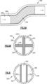
- Figure 3A shows an exhaust for an engine such as engine 100.
- a nacelle 142 surrounds a core housing 144.
- the propulsor 106 provides propulsion for an associated aircraft.
- Propulsor 106 also delivers air into the nacelle 142 as shown at 143. Some of the air passes outwardly of an inner housing 144 to cool the inner housing 144.
- Another portion of the air is pumped into an inlet 148 defined between the housing 144 and an outer exhaust housing 146. That air passes downstream and through an ejector opening 158.
- the products of combustion leaving the engine 100 enter a chamber 161 inward of housing 146 and provide a jet pump at an exit 156 of the housing 146.
- the housing 146 may be thought of as an S-duct arrangement. There is a radially inner first generally axially extending portion 150 leading into a radially outwardly extending portion 152, which then merges into a second generally axially extending portion 154.
- the first generally axially extending portion 150 extends axially away from the engine 100 with a component in an axial direction defined by the rotational axis X of the engine.
- the axial component is greater than a radial component of its direction.
- the first generally axially extending portion 150 merges into radially extending portion 152.
- the radially extending portion 152 merges into the second generally axially extending portion 154.
- Portion 154 extends along a direction with a component in an axial direction that is greater than a radial component.
- the radially extending portion 152 extends with an axial component but also having a radial component that is greater than the radial component in both the first and second axially extending portion 150/154.
- the S-duct In an engine such as engine 100, the S-duct must be made relatively long to provide sufficient area for exhaust noise mitigation and reduce exhaust noise. This is particularly true when an electric motor 114 is utilized in the engine 100.
- Applicant has recognized that breaking the exhaust gas flow in chamber 161 in subportions will help reduce the noise leaving the exhaust duct exit 156.
- a flow divider is provided by a center bullet 160 and struts 162.
- FIG. 3B there are three chambers 163 defined between circumferentially spaced ones of the struts 162.
- the struts 162 may have an aero shape to minimize losses.
- the struts 162 and center bullet 160 thus provide flow dividers.
- Acoustic treatments 170 are shown on an inner surface 147 of outer wall 146 and an outer surface of the center bullet 160. The thickness of treatments 170 is exaggerated for illustration purposes only. In practice they will likely be thinner.
- FIG 4A shows a first embodiment of the acoustic treatment on the bullet 160.
- the acoustic treatment 170 may be a coating of foam or other porous materials such as fiberglass or mesh.
- Mesh treatments include porous materials bagged in a mesh cloth and finished with a perforated sheet to form the skin facing the flow. This avoids contamination/deterioration with hot gases in the exhaust. Similar treatments can be provided on inner surface 147.
- Figure 4B shows an acoustic treatment 270 which includes a plurality of chambers 180 in a flow divider body 174, and having a face plate 176 with small perforations 178 over the chamber 180.
- An acoustic treatment 370 as shown in Figure 4C is shown schematically as a Helmholtz resonator 190 in the center bullet 160.
- the treatments provided on the inner surface 147 may be any of these acoustic treatments, or any other acoustic treatments.
- Possible wall treatments include passive types, such as fibrous, foam, ceramic, and filled cavity with a special handling of the treatment in a package.
- quarter-wavelength resonator type Helmholtz resonators, single and double degree of freedom liners, made up of a perforated skin on honeycomb or partitions, volume tune liner types made up with fined tuned limited volumes on a top of which a perforated skin is bonded, where the perforations have a tuned size and number may all be used.
- Figure 5A shows another exhaust duct embodiment 190 having an outer housing 246 with flow dividers 194.
- flow dividers 194 and 196 which are generally perpendicular to each other to define four separate chambers 292.
- the flow dividers 194/196 and the inner wall 246 will each be provided with acoustic treatment as in the above embodiment.
- Figure 6 shows yet another embodiment 300 wherein there are plural flow dividers 350 which are generally parallel to each other and divide an interior of the outer exhaust wall 346 into three separate chambers 352.
- acoustic treatments will be provided both on the outer surface of the flow dividers 350 and an inner surface of the outer wall 346 will provide effective noise reduction in the turbo-compounded engine.
- the distance or the length of acoustically treated walls is a function of the level of attenuation needed.
- the total length is optimized along with the number of splitters and type of acoustic treatment.
- a turbo-compounded engine 100 under this disclosure could be said to include a piston engine 116 connected to drive a propulsor 106.
- An outlet 120 of the piston engine is operable to connect products of combustion from the piston engine 116 to pass over a turbine 122.
- the turbine 122 is connected to drive a turbine shaft 121 also connected to drive the propulsor 106.
- An outlet of the turbine is connected into an exhaust duct 146 configured to exhaust the products of combustion.
- the exhaust duct 146 is provided with an exhaust duct outer wall 146 defining an exhaust chamber 161.
- a further cooling air outer wall 144 is positioned outwardly of the exhaust duct wall 146.
- Flow dividers are received within an exhaust chamber inward of the exhaust duct outer wall.
- the exhaust duct outer wall has an inner surface and the flow dividers have an outer surface. Acoustic treatments are provided on both the inner surface of the exhaust duct outer wall and the outer surface of the flow dividers.
Landscapes
- Engineering & Computer Science (AREA)
- Mechanical Engineering (AREA)
- Chemical & Material Sciences (AREA)
- Combustion & Propulsion (AREA)
- General Engineering & Computer Science (AREA)
- Aviation & Aerospace Engineering (AREA)
- Exhaust Silencers (AREA)
- Laminated Bodies (AREA)
Abstract
A turbo-compounded engine (100) includes a piston engine (116) connected to drive a propulsor (106). An outlet (132) of the piston engine (116) is operable to connect products of combustion from the piston engine (116) to pass over a turbine (122). The turbine (122) is connected to drive a turbine shaft (121) also connected to drive the propulsor (106). An outlet (132) of the turbine (122) is connected into an exhaust duct (146) configured to exhaust (120) the products of combustion. The exhaust duct (146) is provided with an exhaust duct outer wall (146) defining an exhaust chamber (161). A further cooling air outer wall (144) is positioned outwardly of the exhaust duct (146). Flow dividers (162) are received within an exhaust chamber (161) inward of the exhaust duct outer wall (146). The exhaust duct outer wall (146) has an inner surface (147) and the flow dividers (162) have an outer surface. Acoustic treatment (170) is provided on both the inner surface (147) of the exhaust duct outer wall (146) and the outer surface of the flow dividers (162).
Description
- This application relates to providing acoustic arrangements to reduce exhaust noise in a turbo-compounded engine.
- Engines for aircraft applications typically include a propulsor. In some engines a fan is used and in others a propeller.
- One type of engine that is showing some promise is a turbo-compounded engine. In a turbo-compounded engine there is typically a piston engine driving the propulsor. Exhaust products downstream of the piston engine pass across a turbine. The rotation of the turbine drives a shaft that also provides propulsion to the propulsor.
- Such engines are provided with relatively long exhaust ducts to handle the noise that will be created. Further, the exhaust duct shape needs to fit particular installation challenges for a turboprop.
- Another engine type is an auxiliary power unit ("APU"). These engines do not have a propulsor, but may use turbo-compounded engines. Such APU engines also have noise challenges.
- In one type of turbo-compounded engine an electric motor also supplements the piston engine. The exhaust noise challenges in such engines are particularly acute.
- A turbo-compounded engine includes a piston engine connected to drive a propulsor. An outlet of the piston engine is operable to connect products of combustion from the piston engine to pass over a turbine. The turbine is connected to drive a turbine shaft also connected to drive the propulsor. An outlet of the turbine is connected into an exhaust duct configured to exhaust the products of combustion. The exhaust duct is provided with an exhaust duct outer wall defining an exhaust chamber. A further cooling air outer wall is positioned outwardly of the exhaust duct. Flow dividers are received within an exhaust chamber inward of the exhaust duct outer wall. The exhaust duct outer wall has an inner surface and the flow dividers have an outer surface. Acoustic treatment is provided on both the inner surface of the exhaust duct outer wall and the outer surface of the flow dividers.
- The piston engine may be a rotary engine.
- In an embodiment of any of the above, the exhaust duct outer wall may have a first generally axially extending portion extending away from the engine in a first direction with a first axial component in an axial direction defined by the rotational axis of the engine and a first radial component. The first axial component may be greater than the first radial component. The first axial portion may merge into a radially extending portion. The radially extending portion may merge into a second generally axially extending portion extending along a second direction with a second axial component in the axial direction and a second radial component. The second axial component may be greater than the second radial component. The radially extending portion may extend in a third direction with a third axial component and a third radial component that is greater than the radial component in both the first and second generally axially extending portions (e.g., the third radial component that is greater than each of the first radial component and the second radial component).
- In an embodiment of any of the above, an electric motor may be provided to selectively drive the propulsor.
- In an embodiment of any of the above, the turbine shaft may drive a compressor for delivering compressed air into the piston engine.
- In an embodiment of any of the above, the exhaust duct outer wall may have a first generally axially extending portion extending axially away from the engine with a component in an axial direction defined by the rotational axis of the engine, and the axial component (e.g., the component in an axial direction) being greater than a radial component, the first axial portion merging into a radially extending portion, and the radially extending portion merging into a second generally axially extending portion extending along a direction with a component in an axial direction (e.g., the axial direction) that is greater than a radial component and the radially extending portion extending with an axial component but also having a radial component that is greater than the radial component in both the first and second generally axially extending portion.
- In an embodiment of any of the above, a gear reduction may be provided between an output shaft driven by the piston engine and the propulsor such that the propulsor rotates at a slower speed than the output shaft.
- In an embodiment of any of the above, a compound gearbox may take in rotation from the electric motor, the piston engine and the turbine and drive the output shaft leading into the gear reduction.
- In an embodiment of any of the above, the flow dividers may divide the exhaust chamber into at least three sub-chambers.
- In an embodiment of any of the above, the flow dividers may include a central bullet and struts extending from the central bullet to the inner surface of the exhaust duct outer wall.
- In an embodiment of any of the above, the flow dividers may comprise a plurality of plates extending to be perpendicular to each other to define the sub-chambers.
- In an embodiment of any of the above, the flow dividers may comprise plural crossing plates which extend parallel to each other.
- In an embodiment of any of the above, the acoustic treatment on at least one of the inner surface of the exhaust duct outer wall and the outer surface of the flow dividers may be provided by at least one of a coating, a mesh material, a porous material, a foam or fiberglass.
- In an embodiment of any of the above, the acoustic treatment on at least one of the inner surface of the exhaust duct outer wall and the outer surface of the flow dividers may be provided by a plurality of chambers and an outer face sheet with small perforations extending through the face sheet and into the chambers.
- In an embodiment of any of the above, at least one of the flow dividers may be provided with a Helmholtz resonator.
- These and other features will be best understood from the following drawings and specification, the following is a brief description.
-
-
Figure 1 schematically shows a turbo-compounded engine. -
Figure 2 shows a piston engine incorporated into the turbo-compounded engine ofFigure 1 . -
Figure 3A shows an exhaust duct arrangement for a turbo-compounded engine. -
Figure 3B is a cross-section of theFigure 3A embodiment. -
Figure 4A shows a first acoustic treatment. -
Figure 4B shows a second example acoustic treatment. -
Figure 4C shows yet another alternative acoustic treatment. -
Figure 5A shows a distinct embodiment exhaust duct. -
Figure 5B is a cross-section throughFigure 5A . -
Figure 6 shows yet another exhaust duct embodiment. - A turbo-compounded
engine 100 is illustrated inFigure 1 .Engine 100 is for use on an aircraft. Agear reduction 102 is shown schematically driving ashaft 104 to in turn drive apropulsor 106.Propulsor 106 rotates at a slower speed thanshaft 100 due togear reduction 102. In embodiments thepropulsor 106 could be a propeller. However, it is also within the scope of this disclosure that the propulsor could be a fan. Acompound gearbox 108 takes in several sources of drive to in turn drive ashaft 110 that drives thegear reduction 102. - An
electric motor 114 optionally drives ashaft 112 to provide rotational force into thecompound gearbox 108. - A
piston engine 116 drives ashaft 118 to also provide a source of rotation into thegearbox 108. It is known that the electric motor can provide additional power in combination with thepiston engine 116 under certain operational conditions such as high power conditions. As an example, at takeoff both theelectric motor 114 and thepiston engine 116 may be utilized. At lower power conditions, such as cruise, perhaps only theelectric motor 114 is used. - A
compound gearbox 123 receives rotation from ashaft 121. Anexhaust 120 from thepiston engine 116 passes across aturbine 122. Theturbine 122 drives theshaft 121 through thegearbox 123 to provide additional rotational force toshaft 118. Theturbine 122 is also shown driving acompressor 124. The compressed air fromcompressor 124 passes through aheat exchanger 125 and then to thepiston engine 116 throughline 127. -
Figure 2 shows an example of thepiston engine 116. A rotary piston engine, such as a Wankel engine is illustrated. Apiston 126 rotates within achamber 128. Compressed air at 130 is injected into thechamber 128 fromline 127. It is mixed with fuel and ignited and drives thepiston 126. The products of combustion pass throughoutlet 132 and intoline 120. - The operation of the
engines - It is also known that a turbo-compounded engine could have a piston engine with a plurality of engines such as
engine 116 as shown inFigure 2 . Further, it is known that the piston engine could be a reciprocating piston. - As mentioned above, there are challenges with exhaust noise in such engines, because of the pulsation nature of the rotary core.
-
Figure 3A shows an exhaust for an engine such asengine 100. Anacelle 142 surrounds acore housing 144. Thepropulsor 106 provides propulsion for an associated aircraft.Propulsor 106 also delivers air into thenacelle 142 as shown at 143. Some of the air passes outwardly of aninner housing 144 to cool theinner housing 144. - While a propulsor is shown, the teachings of this disclosure extends to turbo-compounded engines in non-propulsor applications, such as APUs.
- Another portion of the air is pumped into an
inlet 148 defined between thehousing 144 and anouter exhaust housing 146. That air passes downstream and through anejector opening 158. - The products of combustion leaving the
engine 100 enter achamber 161 inward ofhousing 146 and provide a jet pump at anexit 156 of thehousing 146. - The
housing 146 may be thought of as an S-duct arrangement. There is a radially inner first generally axially extendingportion 150 leading into a radially outwardly extendingportion 152, which then merges into a second generally axially extendingportion 154. - The first generally axially extending
portion 150 extends axially away from theengine 100 with a component in an axial direction defined by the rotational axis X of the engine. The axial component is greater than a radial component of its direction. - The first generally axially extending
portion 150 merges into radially extendingportion 152. Theradially extending portion 152 merges into the second generally axially extendingportion 154. -
Portion 154 extends along a direction with a component in an axial direction that is greater than a radial component. - The
radially extending portion 152 extends with an axial component but also having a radial component that is greater than the radial component in both the first and second axially extendingportion 150/154. - In an engine such as
engine 100, the S-duct must be made relatively long to provide sufficient area for exhaust noise mitigation and reduce exhaust noise. This is particularly true when anelectric motor 114 is utilized in theengine 100. - Applicant has recognized that breaking the exhaust gas flow in
chamber 161 in subportions will help reduce the noise leaving theexhaust duct exit 156. - Thus, a flow divider is provided by a
center bullet 160 and struts 162. - As shown in
Figure 3B , there are threechambers 163 defined between circumferentially spaced ones of thestruts 162. Thestruts 162 may have an aero shape to minimize losses. Thestruts 162 andcenter bullet 160 thus provide flow dividers.Acoustic treatments 170 are shown on an inner surface 147 ofouter wall 146 and an outer surface of thecenter bullet 160. The thickness oftreatments 170 is exaggerated for illustration purposes only. In practice they will likely be thinner. -
Figure 4A shows a first embodiment of the acoustic treatment on thebullet 160. Theacoustic treatment 170 may be a coating of foam or other porous materials such as fiberglass or mesh. Mesh treatments include porous materials bagged in a mesh cloth and finished with a perforated sheet to form the skin facing the flow. This avoids contamination/deterioration with hot gases in the exhaust. Similar treatments can be provided on inner surface 147. - Alternatively,
Figure 4B shows anacoustic treatment 270 which includes a plurality ofchambers 180 in aflow divider body 174, and having aface plate 176 withsmall perforations 178 over thechamber 180. - An
acoustic treatment 370 as shown inFigure 4C is shown schematically as aHelmholtz resonator 190 in thecenter bullet 160. - The treatments provided on the inner surface 147 may be any of these acoustic treatments, or any other acoustic treatments.
- Possible wall treatments include passive types, such as fibrous, foam, ceramic, and filled cavity with a special handling of the treatment in a package.
- Further, quarter-wavelength resonator type, Helmholtz resonators, single and double degree of freedom liners, made up of a perforated skin on honeycomb or partitions, volume tune liner types made up with fined tuned limited volumes on a top of which a perforated skin is bonded, where the perforations have a tuned size and number may all be used.
-
Figure 5A shows anotherexhaust duct embodiment 190 having anouter housing 246 withflow dividers 194. - As shown in
Figure 5B , there are crossingflow dividers separate chambers 292. Theflow dividers 194/196 and theinner wall 246 will each be provided with acoustic treatment as in the above embodiment. -
Figure 6 shows yet anotherembodiment 300 wherein there areplural flow dividers 350 which are generally parallel to each other and divide an interior of theouter exhaust wall 346 into threeseparate chambers 352. Here again, acoustic treatments will be provided both on the outer surface of theflow dividers 350 and an inner surface of theouter wall 346 will provide effective noise reduction in the turbo-compounded engine. - The distance or the length of acoustically treated walls is a function of the level of attenuation needed. The total length is optimized along with the number of splitters and type of acoustic treatment.
- A turbo-compounded
engine 100 under this disclosure could be said to include apiston engine 116 connected to drive apropulsor 106. Anoutlet 120 of the piston engine is operable to connect products of combustion from thepiston engine 116 to pass over aturbine 122. Theturbine 122 is connected to drive aturbine shaft 121 also connected to drive thepropulsor 106. An outlet of the turbine is connected into anexhaust duct 146 configured to exhaust the products of combustion. Theexhaust duct 146 is provided with an exhaust ductouter wall 146 defining anexhaust chamber 161. A further cooling airouter wall 144 is positioned outwardly of theexhaust duct wall 146. Flow dividers are received within an exhaust chamber inward of the exhaust duct outer wall. The exhaust duct outer wall has an inner surface and the flow dividers have an outer surface. Acoustic treatments are provided on both the inner surface of the exhaust duct outer wall and the outer surface of the flow dividers. - Although an embodiment has been disclosed, a worker of ordinary skill in this art would recognize that modifications would come within the scope of this disclosure. Thus, the following claims should be studied to determine the true scope and content of this disclosure.
Claims (15)
- A turbo-compounded engine (100) comprising:a piston engine (116) connected to drive a propulsor (106), an outlet (132) of the piston engine (116) being configured to connect products of combustion from the piston engine (116) to pass over a turbine (122), the turbine (122) being connected to drive a turbine shaft (121) connected to drive the propulsor (106);an outlet of the turbine (122) connected into an exhaust duct (146) configured to exhaust the products of combustion, the exhaust duct (146) being provided with an exhaust duct outer wall (146) defining an exhaust chamber (161), and a cooling air outer wall (144) positioned outwardly of the exhaust duct (146); andflow dividers (160, 162, 194, 196, 350) received within the exhaust chamber (161) inward of the exhaust duct outer wall (146), the exhaust duct outer wall (146) having an inner surface (147) and the flow dividers (160, 162, 194, 196, 350) having an outer surface, and acoustic treatment (170) being provided on both the inner surface (147) of the exhaust duct outer wall (146) and the outer surface of the flow dividers (160, 162, 194, 196,350).
- The engine (100) as set forth in claim 1, wherein the piston engine (116) is a rotary engine (100).
- The engine (100) as set forth in claim 1 or 2, wherein:the exhaust duct outer wall (146) has a first generally axially extending portion (150) extending away from the engine (116) in a first direction with a first axial component in an axial direction defined by the rotational axis of the engine (116) and a first radial component, the first axial component being greater than the first radial component; andthe first axial portion (150) merging into a radially extending portion (152), and the radially extending portion (152) merging into a second generally axially extending portion (154) extending along a second direction with a second axial component in the axial direction and a second radial component, the second axial component being greater than the second radial component, andthe radially extending portion (152) extending in a third direction with a third axial component and a third radial component that is greater than the radial component in both the first and second generally axially extending portion (154).
- The engine (100) as set forth in claim 1 or 2, wherein the exhaust duct outer wall (146) has a first generally axially extending portion (150) extending axially away from the engine (100) with a component in an axial direction defined by the rotational axis of the engine (100), and the axial component being greater than a radial component, the first axial portion (154) merging into a radially extending portion (152), and the radially extending portion (152) merging into a second generally axially extending portion (154) extending along a direction with a component in an axial direction that is greater than a radial component and the radially extending portion (152) extending with an axial component but also having a radial component that is greater than the radial component in both the first and second generally axially extending portion (154).
- The engine (100) as set forth in any preceding claim, wherein the turbine shaft (121) further drives a compressor (124) for delivering compressed air into the piston engine (116).
- The engine (100) as set forth in any preceding claim, further comprising an electric motor (114) configured to selectively drive the propulsor (106).
- The engine (100) as set forth in any preceding claim, wherein a gear reduction (102) is provided between an output shaft (104) driven by the piston engine (116) and the propulsor (106) such that the propulsor (106) rotates at a slower speed than the output shaft (104).
- The engine as set forth in claim 7, wherein a compound gearbox (108) receives rotational input from a or the electric motor (114), the piston engine (116) and the turbine (122) and drives the output shaft (104) leading into the gear reduction (102).
- The engine (100) as set forth in any preceding claim, wherein the flow dividers (160, 162, 194, 196, 350) divide the exhaust chamber (161) into at least three sub-chambers (163).
- The engine (100) as set forth in any preceding claim, wherein the flow dividers (160, 162) include a central bullet (160) and struts (162) extending from the central bullet (160) to the inner surface (147) of the exhaust duct outer wall (146).
- The engine (100) as set forth in any of claims 1 to 9, wherein the flow dividers (194, 196) are a plurality of plates extending to be perpendicular to each other to define a plurality of sub-chambers (292).
- The engine (100) as set forth in any of claims 1 to 9, wherein the flow dividers (350) are plural crossing plates which extend parallel to each other.
- The engine (100) as set forth in any preceding claim, wherein the acoustic treatment (170) on at least one of the inner surface (147) of the exhaust duct outer wall (146) and the outer surface of the flow dividers (194) is provided by a coating, a mesh material, a porous material, a foam or fiberglass.
- The engine (100) as set forth in any preceding claim, wherein the acoustic treatment (170) on at least one of the inner surface (147) of the exhaust duct outer wall (146) and the outer surface of the flow dividers (194) is provided by a plurality of chambers (163) and an outer face sheet with perforations (178) extending through the face sheet and into the chambers (163).
- The engine (100) as set forth in any preceding claim, wherein at least one of the flow dividers (194) is provided with a Helmholtz resonator (190).
Applications Claiming Priority (1)
| Application Number | Priority Date | Filing Date | Title |
|---|---|---|---|
| US18/341,211 US12415611B2 (en) | 2023-06-26 | 2023-06-26 | Turbo-compounded engine with exhaust duct acoustic arrangement |
Publications (1)
| Publication Number | Publication Date |
|---|---|
| EP4484739A1 true EP4484739A1 (en) | 2025-01-01 |
Family
ID=91700258
Family Applications (1)
| Application Number | Title | Priority Date | Filing Date |
|---|---|---|---|
| EP24184811.8A Pending EP4484739A1 (en) | 2023-06-26 | 2024-06-26 | Turbo-compounded engine with exhaust duct acoustic arrangement |
Country Status (3)
| Country | Link |
|---|---|
| US (2) | US12415611B2 (en) |
| EP (1) | EP4484739A1 (en) |
| CA (1) | CA3241824A1 (en) |
Cited By (1)
| Publication number | Priority date | Publication date | Assignee | Title |
|---|---|---|---|---|
| EP4749116A1 (en) * | 2024-11-26 | 2026-05-27 | Pratt & Whitney Canada Corp. | Bifurcated exhaust duct for hybrid aircraft powerplant |
Citations (3)
| Publication number | Priority date | Publication date | Assignee | Title |
|---|---|---|---|---|
| US2958388A (en) * | 1958-01-30 | 1960-11-01 | Chris H Paulsen | Muffler |
| US4263982A (en) * | 1979-08-06 | 1981-04-28 | Feuling James J | Muffler for internal combustion engines and method of manufacturing same |
| US20200307812A1 (en) * | 2019-03-29 | 2020-10-01 | Pratt & Whitney Canada Corp. | Hybrid aircraft propulsion power plants |
Family Cites Families (8)
| Publication number | Priority date | Publication date | Assignee | Title |
|---|---|---|---|---|
| US3177972A (en) | 1960-12-14 | 1965-04-13 | Garrett Corp | Sound absorbing gas turbine exhaust duct |
| US4244441A (en) | 1979-07-31 | 1981-01-13 | The Garrett Corporation | Broad band acoustic attenuator |
| US5936210A (en) * | 1998-01-15 | 1999-08-10 | Maremont Exhaust Products, Inc. | High performance muffler |
| FR2787513B1 (en) * | 1998-12-17 | 2001-01-19 | Turbomeca | MULTICHANNEL EXHAUST DEVICE FOR ACOUSTICALLY TREATED TURBOMACHINE |
| US7717229B2 (en) | 2008-05-09 | 2010-05-18 | Siemens Energy, Inc. | Gas turbine exhaust sound suppressor and associated methods |
| US8656888B2 (en) | 2011-07-28 | 2014-02-25 | Pratt & Whitney Canada Corp. | Rotary internal combustion engine with variable volumetric compression ratio |
| US9194232B2 (en) | 2012-07-20 | 2015-11-24 | Pratt & Whitney Canada Corp. | Compound cycle engine |
| US11535392B2 (en) | 2019-03-18 | 2022-12-27 | Pratt & Whitney Canada Corp. | Architectures for hybrid-electric propulsion |
-
2023
- 2023-06-26 US US18/341,211 patent/US12415611B2/en active Active
-
2024
- 2024-06-17 CA CA3241824A patent/CA3241824A1/en active Pending
- 2024-06-26 EP EP24184811.8A patent/EP4484739A1/en active Pending
-
2025
- 2025-09-12 US US19/327,146 patent/US20260077875A1/en active Pending
Patent Citations (3)
| Publication number | Priority date | Publication date | Assignee | Title |
|---|---|---|---|---|
| US2958388A (en) * | 1958-01-30 | 1960-11-01 | Chris H Paulsen | Muffler |
| US4263982A (en) * | 1979-08-06 | 1981-04-28 | Feuling James J | Muffler for internal combustion engines and method of manufacturing same |
| US20200307812A1 (en) * | 2019-03-29 | 2020-10-01 | Pratt & Whitney Canada Corp. | Hybrid aircraft propulsion power plants |
Cited By (1)
| Publication number | Priority date | Publication date | Assignee | Title |
|---|---|---|---|---|
| EP4749116A1 (en) * | 2024-11-26 | 2026-05-27 | Pratt & Whitney Canada Corp. | Bifurcated exhaust duct for hybrid aircraft powerplant |
Also Published As
| Publication number | Publication date |
|---|---|
| US20240425192A1 (en) | 2024-12-26 |
| US12415611B2 (en) | 2025-09-16 |
| US20260077875A1 (en) | 2026-03-19 |
| CA3241824A1 (en) | 2025-10-31 |
Similar Documents
| Publication | Publication Date | Title |
|---|---|---|
| CN113217582B (en) | Gear box for engine | |
| EP3869499B1 (en) | Acoustic liner with non-uniform volumetric distribution | |
| EP2971659B1 (en) | Acoustic liner with varied properties | |
| CN114909215A (en) | Propulsion system configuration and method of operation | |
| US20260077875A1 (en) | Turbo-compounded engine with exhaust duct acoustic arrangement | |
| US7993099B2 (en) | Helicopter gas turbine engine with sound level lowered by ejector hush kitting | |
| US20120167574A1 (en) | Gas turbine engine and combustion liner | |
| GB2405181A (en) | Low noise emission turbomachine | |
| US10677163B2 (en) | Noise attenuation structures | |
| EP2540993A1 (en) | Aircraft gas turbine | |
| CN116806353A (en) | Reduced volume acoustic treatment panel for turbojet engine | |
| CA3166771A1 (en) | Bleed air offtake assembly for a gas turbine engine | |
| EP4484740A1 (en) | Cooling flow injection to alter exhaust boundary conditions in a turbo-compounded engine | |
| EP3892546A1 (en) | Transpirationally cooled exhaust center body for an aircraft propulsion system | |
| EP4310299B1 (en) | Flow deflector for aperture in gas turbine engine flowpath wall | |
| EP4450789A2 (en) | Acoustic panel with non-linear variable percentage of open area | |
| EP3273030B1 (en) | Embedded engine using boundary layer cooling air | |
| EP4317661A1 (en) | Porous cover for a takeoff port of a gas turbine engine | |
| CN116892446A (en) | Gas turbine engine with compressed air injection assembly | |
| EP4600947A1 (en) | Acoustic panel with different cell configurations | |
| US20250236386A1 (en) | Rotorcraft with powerplant exhaust sound attenuation | |
| EP4650661A1 (en) | Turbine engine having a multicavity damper | |
| EP4549701B1 (en) | Combined gas turbine engine vane and blade outer air seal assembly and gas turbine engine | |
| EP4332364A1 (en) | Engine exhaust nozzle with acoustic attenuation | |
| US20240328361A1 (en) | Acoustic panel with non-linear variable percentage of open area |
Legal Events
| Date | Code | Title | Description |
|---|---|---|---|
| PUAI | Public reference made under article 153(3) epc to a published international application that has entered the european phase |
Free format text: ORIGINAL CODE: 0009012 |
|
| STAA | Information on the status of an ep patent application or granted ep patent |
Free format text: STATUS: THE APPLICATION HAS BEEN PUBLISHED |
|
| AK | Designated contracting states |
Kind code of ref document: A1 Designated state(s): AL AT BE BG CH CY CZ DE DK EE ES FI FR GB GR HR HU IE IS IT LI LT LU LV MC ME MK MT NL NO PL PT RO RS SE SI SK SM TR |
|
| STAA | Information on the status of an ep patent application or granted ep patent |
Free format text: STATUS: REQUEST FOR EXAMINATION WAS MADE |
|
| 17P | Request for examination filed |
Effective date: 20250701 |