EP4484737A1 - Method of operating an internal combustion engine, control arrangement, computer program, computer-readable medium, and engine - Google Patents
Method of operating an internal combustion engine, control arrangement, computer program, computer-readable medium, and engine Download PDFInfo
- Publication number
- EP4484737A1 EP4484737A1 EP23182740.3A EP23182740A EP4484737A1 EP 4484737 A1 EP4484737 A1 EP 4484737A1 EP 23182740 A EP23182740 A EP 23182740A EP 4484737 A1 EP4484737 A1 EP 4484737A1
- Authority
- EP
- European Patent Office
- Prior art keywords
- engine
- exhaust
- state
- controlling
- cylinders
- Prior art date
- Legal status (The legal status is an assumption and is not a legal conclusion. Google has not performed a legal analysis and makes no representation as to the accuracy of the status listed.)
- Pending
Links
Images


Classifications
-
- F—MECHANICAL ENGINEERING; LIGHTING; HEATING; WEAPONS; BLASTING
- F02—COMBUSTION ENGINES; HOT-GAS OR COMBUSTION-PRODUCT ENGINE PLANTS
- F02D—CONTROLLING COMBUSTION ENGINES
- F02D41/00—Electrical control of supply of combustible mixture or its constituents
- F02D41/02—Circuit arrangements for generating control signals
- F02D41/021—Introducing corrections for particular conditions exterior to the engine
- F02D41/0235—Introducing corrections for particular conditions exterior to the engine in relation with the state of the exhaust gas treating apparatus
- F02D41/024—Introducing corrections for particular conditions exterior to the engine in relation with the state of the exhaust gas treating apparatus to increase temperature of the exhaust gas treating apparatus
- F02D41/0255—Introducing corrections for particular conditions exterior to the engine in relation with the state of the exhaust gas treating apparatus to increase temperature of the exhaust gas treating apparatus to accelerate the warming-up of the exhaust gas treating apparatus at engine start
-
- F—MECHANICAL ENGINEERING; LIGHTING; HEATING; WEAPONS; BLASTING
- F01—MACHINES OR ENGINES IN GENERAL; ENGINE PLANTS IN GENERAL; STEAM ENGINES
- F01N—GAS-FLOW SILENCERS OR EXHAUST APPARATUS FOR MACHINES OR ENGINES IN GENERAL; GAS-FLOW SILENCERS OR EXHAUST APPARATUS FOR INTERNAL-COMBUSTION ENGINES
- F01N13/00—Exhaust or silencing apparatus characterised by constructional features
- F01N13/009—Exhaust or silencing apparatus characterised by constructional features having two or more separate purifying devices arranged in series
-
- F—MECHANICAL ENGINEERING; LIGHTING; HEATING; WEAPONS; BLASTING
- F01—MACHINES OR ENGINES IN GENERAL; ENGINE PLANTS IN GENERAL; STEAM ENGINES
- F01N—GAS-FLOW SILENCERS OR EXHAUST APPARATUS FOR MACHINES OR ENGINES IN GENERAL; GAS-FLOW SILENCERS OR EXHAUST APPARATUS FOR INTERNAL-COMBUSTION ENGINES
- F01N3/00—Exhaust or silencing apparatus having means for purifying, rendering innocuous, or otherwise treating exhaust
- F01N3/08—Exhaust or silencing apparatus having means for purifying, rendering innocuous, or otherwise treating exhaust for rendering innocuous
- F01N3/10—Exhaust or silencing apparatus having means for purifying, rendering innocuous, or otherwise treating exhaust for rendering innocuous by thermal or catalytic conversion of noxious components of exhaust
-
- F—MECHANICAL ENGINEERING; LIGHTING; HEATING; WEAPONS; BLASTING
- F01—MACHINES OR ENGINES IN GENERAL; ENGINE PLANTS IN GENERAL; STEAM ENGINES
- F01N—GAS-FLOW SILENCERS OR EXHAUST APPARATUS FOR MACHINES OR ENGINES IN GENERAL; GAS-FLOW SILENCERS OR EXHAUST APPARATUS FOR INTERNAL-COMBUSTION ENGINES
- F01N3/00—Exhaust or silencing apparatus having means for purifying, rendering innocuous, or otherwise treating exhaust
- F01N3/08—Exhaust or silencing apparatus having means for purifying, rendering innocuous, or otherwise treating exhaust for rendering innocuous
- F01N3/10—Exhaust or silencing apparatus having means for purifying, rendering innocuous, or otherwise treating exhaust for rendering innocuous by thermal or catalytic conversion of noxious components of exhaust
- F01N3/24—Exhaust or silencing apparatus having means for purifying, rendering innocuous, or otherwise treating exhaust for rendering innocuous by thermal or catalytic conversion of noxious components of exhaust characterised by constructional aspects of converting apparatus
- F01N3/28—Construction of catalytic reactors
- F01N3/2892—Exhaust flow directors or the like, e.g. upstream of catalytic device
-
- F—MECHANICAL ENGINEERING; LIGHTING; HEATING; WEAPONS; BLASTING
- F01—MACHINES OR ENGINES IN GENERAL; ENGINE PLANTS IN GENERAL; STEAM ENGINES
- F01N—GAS-FLOW SILENCERS OR EXHAUST APPARATUS FOR MACHINES OR ENGINES IN GENERAL; GAS-FLOW SILENCERS OR EXHAUST APPARATUS FOR INTERNAL-COMBUSTION ENGINES
- F01N9/00—Electrical control of exhaust gas treating apparatus
-
- F—MECHANICAL ENGINEERING; LIGHTING; HEATING; WEAPONS; BLASTING
- F02—COMBUSTION ENGINES; HOT-GAS OR COMBUSTION-PRODUCT ENGINE PLANTS
- F02D—CONTROLLING COMBUSTION ENGINES
- F02D13/00—Controlling the engine output power by varying inlet or exhaust valve operating characteristics, e.g. timing
- F02D13/02—Controlling the engine output power by varying inlet or exhaust valve operating characteristics, e.g. timing during engine operation
- F02D13/0203—Variable control of intake and exhaust valves
- F02D13/0215—Variable control of intake and exhaust valves changing the valve timing only
-
- F—MECHANICAL ENGINEERING; LIGHTING; HEATING; WEAPONS; BLASTING
- F02—COMBUSTION ENGINES; HOT-GAS OR COMBUSTION-PRODUCT ENGINE PLANTS
- F02D—CONTROLLING COMBUSTION ENGINES
- F02D41/00—Electrical control of supply of combustible mixture or its constituents
- F02D41/0002—Controlling intake air
-
- F—MECHANICAL ENGINEERING; LIGHTING; HEATING; WEAPONS; BLASTING
- F02—COMBUSTION ENGINES; HOT-GAS OR COMBUSTION-PRODUCT ENGINE PLANTS
- F02D—CONTROLLING COMBUSTION ENGINES
- F02D41/00—Electrical control of supply of combustible mixture or its constituents
- F02D41/02—Circuit arrangements for generating control signals
- F02D41/021—Introducing corrections for particular conditions exterior to the engine
- F02D41/0235—Introducing corrections for particular conditions exterior to the engine in relation with the state of the exhaust gas treating apparatus
- F02D41/024—Introducing corrections for particular conditions exterior to the engine in relation with the state of the exhaust gas treating apparatus to increase temperature of the exhaust gas treating apparatus
- F02D41/0245—Introducing corrections for particular conditions exterior to the engine in relation with the state of the exhaust gas treating apparatus to increase temperature of the exhaust gas treating apparatus by increasing temperature of the exhaust gas leaving the engine
-
- F—MECHANICAL ENGINEERING; LIGHTING; HEATING; WEAPONS; BLASTING
- F02—COMBUSTION ENGINES; HOT-GAS OR COMBUSTION-PRODUCT ENGINE PLANTS
- F02D—CONTROLLING COMBUSTION ENGINES
- F02D41/00—Electrical control of supply of combustible mixture or its constituents
- F02D41/02—Circuit arrangements for generating control signals
- F02D41/04—Introducing corrections for particular operating conditions
- F02D41/08—Introducing corrections for particular operating conditions for idling
-
- F—MECHANICAL ENGINEERING; LIGHTING; HEATING; WEAPONS; BLASTING
- F02—COMBUSTION ENGINES; HOT-GAS OR COMBUSTION-PRODUCT ENGINE PLANTS
- F02D—CONTROLLING COMBUSTION ENGINES
- F02D41/00—Electrical control of supply of combustible mixture or its constituents
- F02D41/02—Circuit arrangements for generating control signals
- F02D41/14—Introducing closed-loop corrections
- F02D41/1438—Introducing closed-loop corrections using means for determining characteristics of the combustion gases; Sensors therefor
- F02D41/1444—Introducing closed-loop corrections using means for determining characteristics of the combustion gases; Sensors therefor characterised by the characteristics of the combustion gases
- F02D41/1446—Introducing closed-loop corrections using means for determining characteristics of the combustion gases; Sensors therefor characterised by the characteristics of the combustion gases the characteristics being exhaust temperatures
-
- F—MECHANICAL ENGINEERING; LIGHTING; HEATING; WEAPONS; BLASTING
- F02—COMBUSTION ENGINES; HOT-GAS OR COMBUSTION-PRODUCT ENGINE PLANTS
- F02D—CONTROLLING COMBUSTION ENGINES
- F02D9/00—Controlling engines by throttling air or fuel-and-air induction conduits or exhaust conduits
- F02D9/08—Throttle valves specially adapted therefor; Arrangements of such valves in conduits
-
- F—MECHANICAL ENGINEERING; LIGHTING; HEATING; WEAPONS; BLASTING
- F01—MACHINES OR ENGINES IN GENERAL; ENGINE PLANTS IN GENERAL; STEAM ENGINES
- F01N—GAS-FLOW SILENCERS OR EXHAUST APPARATUS FOR MACHINES OR ENGINES IN GENERAL; GAS-FLOW SILENCERS OR EXHAUST APPARATUS FOR INTERNAL-COMBUSTION ENGINES
- F01N2240/00—Combination or association of two or more different exhaust treating devices, or of at least one such device with an auxiliary device, not covered by indexing codes F01N2230/00 or F01N2250/00, one of the devices being
- F01N2240/20—Combination or association of two or more different exhaust treating devices, or of at least one such device with an auxiliary device, not covered by indexing codes F01N2230/00 or F01N2250/00, one of the devices being a flow director or deflector
-
- F—MECHANICAL ENGINEERING; LIGHTING; HEATING; WEAPONS; BLASTING
- F01—MACHINES OR ENGINES IN GENERAL; ENGINE PLANTS IN GENERAL; STEAM ENGINES
- F01N—GAS-FLOW SILENCERS OR EXHAUST APPARATUS FOR MACHINES OR ENGINES IN GENERAL; GAS-FLOW SILENCERS OR EXHAUST APPARATUS FOR INTERNAL-COMBUSTION ENGINES
- F01N2240/00—Combination or association of two or more different exhaust treating devices, or of at least one such device with an auxiliary device, not covered by indexing codes F01N2230/00 or F01N2250/00, one of the devices being
- F01N2240/36—Combination or association of two or more different exhaust treating devices, or of at least one such device with an auxiliary device, not covered by indexing codes F01N2230/00 or F01N2250/00, one of the devices being an exhaust flap
-
- F—MECHANICAL ENGINEERING; LIGHTING; HEATING; WEAPONS; BLASTING
- F02—COMBUSTION ENGINES; HOT-GAS OR COMBUSTION-PRODUCT ENGINE PLANTS
- F02D—CONTROLLING COMBUSTION ENGINES
- F02D41/00—Electrical control of supply of combustible mixture or its constituents
- F02D41/0002—Controlling intake air
- F02D2041/001—Controlling intake air for engines with variable valve actuation
-
- F—MECHANICAL ENGINEERING; LIGHTING; HEATING; WEAPONS; BLASTING
- F02—COMBUSTION ENGINES; HOT-GAS OR COMBUSTION-PRODUCT ENGINE PLANTS
- F02D—CONTROLLING COMBUSTION ENGINES
- F02D2200/00—Input parameters for engine control
- F02D2200/02—Input parameters for engine control the parameters being related to the engine
- F02D2200/08—Exhaust gas treatment apparatus parameters
- F02D2200/0802—Temperature of the exhaust gas treatment apparatus
Definitions
- the present disclosure relates to a method of operating an internal combustion engine.
- the present disclosure further relates to a control arrangement for an internal combustion engine, a computer program, a computer-readable medium, an engine, and a vehicle.
- Internal combustion engines such as four-stroke internal combustion engines, comprise one or more cylinders and a piston arranged in each cylinder.
- the pistons are connected to a crankshaft of the engine and are arranged to reciprocate within the cylinders upon rotation of the crankshaft.
- the engine usually further comprises one or more inlet valves and one or more outlet valves as well as one or more fuel supply arrangements.
- the one or more inlet valves and outlet valves are controlled by a respective valve control arrangement usually comprising one or more camshafts rotatably connected to a crankshaft of the engine, via a belt, chain, gears, or similar.
- a four-stroke internal combustion engine completes four separate strokes while turning a crankshaft.
- a stroke refers to the full travel of the piston along the cylinder, in either direction.
- the uppermost position of the piston in the cylinder is usually referred to as the top dead centre TDC, and the lowermost position of the piston in the cylinder is usually referred to as the bottom dead centre BDC.
- the strokes are completed in the following order, inlet stroke, compression stroke, expansion stroke and exhaust stroke.
- the inlet valve control arrangement controls inlet valves of a cylinder to an open state during the inlet stroke of a piston within the cylinder, to allow air, or a mixture of air and fuel, to enter the cylinder.
- all valves should be closed to allow compression of the air, or the mixture of the air and fuel, in the cylinder. If the engine is in a power producing state, fuel in the cylinder is ignited, usually towards the end of the compression stroke, for example by a spark plug or by compression heat in the cylinder.
- the combustion of fuel within the cylinder significantly increases pressure and temperature in the cylinder.
- the combustion of the fuel usually continues into a significant portion of the subsequent expansion stroke.
- the increased pressure and temperature in the cylinder obtained by the combustion is partially converted into mechanical work supplied to the crank shaft during the expansion stroke.
- all valves should remain closed during the expansion stroke to allow the increased pressure and temperature to be converted into mechanical work.
- the expansion stroke is also usually referred to as the combustion stroke, since usually, most of the combustion takes place during the expansion stroke.
- the exhaust valve control arrangement controls exhaust valves of the cylinder to an open state to allow exhaust gases to be expelled out of the cylinder into an exhaust system of the combustion engine.
- auxiliary braking system is a so called exhaust brake which comprises an exhaust throttle arranged in the exhaust system of the engine.
- the exhaust throttle is controllable between an open state and a closed state, wherein the exhaust throttle restricts the flow of gas through the exhaust system to thereby generate a backpressure when controlled to the closed state.
- the backpressure opposes the upward motion of the pistons when they are moving toward the top dead centre in the exhaust stroke, which thereby increases the braking torque of the engine.
- exhausts from an engine can comprise carbon monoxide CO from incomplete combustion, hydrocarbons HC from unburnt fuel, nitrogen oxides NOx from high combustion temperatures, and particulate matter which is usually abbreviated PM and consists mostly of soot/smoke.
- Nitrogen oxides NOx are formed by a reaction between oxygen 02 and nitrogen N upon high temperatures and pressures in a cylinder of an engine. In other words, when the operation of the engine is optimized regarding fuel efficiently, large amounts of nitrogen oxides NOx may be formed.
- Exhaust gas recirculation (EGR) is an effective strategy to control the NOx emissions from engines. EGR works by recirculating a portion of an engine's exhaust gas back to the engine cylinders. The EGR reduces the formation of NOx through lowering the oxygen concentration in the combustion chamber, as well as through heat absorption, which reduces peak in-cylinder temperatures.
- a selective catalytic reduction arrangement is a means of converting nitrogen oxides, also referred to as NOx with the aid of a catalyst into diatomic nitrogen N2, and water H2O.
- a gaseous reductant typically anhydrous ammonia, aqueous ammonia, or urea is added to a stream of exhaust gas and is adsorbed onto a catalytic substrate.
- the conversion efficiency rate of these exhaust aftertreatment systems highly depends on the high temperature of the exhaust gases. Therefore, problems may arise in the converting efficiency of an exhaust aftertreatment system if the engine is operated to generate a low exhaust temperature, especially during cold starts, low engine load conditions, during engine idling, and similar operating conditions. Therefore, at certain times and/or conditions, it can be desired to operate the engine to increase the exhaust temperature even if it has a negative impact on the fuel consumption of the engine.
- Engine idling refers to the operation of an internal combustion engine when it is running but not actively engaged in performing any useful work. During engine idling, the engine is operated to run at a low speed, typically around 600 to 1000 revolutions per minute (RPM), to maintain basic functions such as powering the vehicle's electrical systems, operating air conditioning or heating, and allowing for a quick restart when necessary.
- RPM revolutions per minute
- the exhaust flow to be heated should be minimized.
- the throttling of the exhaust gas by the exhaust throttle is not enough for keeping engine speed from rising at sufficient fuel quantity for the desired temperature.
- the engine would still have combustion stability issues at small exhaust flow and low fuel injection levels.
- the object is achieved by a method of operating an internal combustion engine, wherein the method is performed by a control arrangement, and wherein the engine comprises a number of cylinders, a piston arranged in each cylinder to delimit a combustion chamber inside the cylinder, an exhaust system comprising one or more catalytic converters and an exhaust throttle controllable between an open state and a closed state, and a flow control assembly controllable between a first state to provide a nominal amount of gas pumped from the number of cylinders into the exhaust system and a second state to provide a reduced amount of gas pumped from the number of cylinders into the exhaust system.
- the method comprises, during idling of the engine:
- the method comprises the step of switching in an alternating manner between the first and second modes of operation, a method is provided having conditions for maintaining a temperature of the one or more catalytic converters above a lower threshold temperature while minimizing the fuel consumption of the engine during idling of the engine.
- the method comprises the steps of controlling the flow control assembly to provide the nominal amount of gas pumped from the number of cylinders into the exhaust system and controlling the exhaust throttle to the closed state when operating the engine in the first mode of operation. Accordingly, the one or more catalytic converters will be heated in an efficient manner when the engine is operated in the first mode of operation. Therefore, the first mode of operation, as referred to herein, may also be referred to as a heating mode.
- the method comprises the steps of controlling the flow control assembly to provide the reduced amount of gas pumped from the number of cylinders into the exhaust system and controlling the exhaust throttle to the open state when operating the engine in the second mode of operation.
- the reduced amount of gas pumped from the number of cylinders into the exhaust system results in a low cooling rate of the one or more catalytic converters and the controlling of the exhaust throttle to the open state can ensure combustion stability despite a low flow of gas through the engine and a low fuel injection rate in the second mode of operation. Therefore, the second mode of operation, as referred to herein, may also be referred to as a temperature saving mode.
- a method having conditions for maintaining a temperature of the one or more catalytic converters above a lower threshold temperature while minimizing the fuel consumption of the engine during idling of the engine.
- the temperature of the one or more catalytic converters can be maintained above a lower threshold temperature, the conversion efficiency rate thereof can be maintained while ensuring a low fuel consumption of the engine during idling.
- a method is provided having conditions for meeting upcoming emission legislations while minimizing the fuel consumption of the engine.
- the method comprises:
- the method comprises:
- the one or more catalytic converters is/are heated in an efficient manner when the temperature estimate declines below the lower threshold temperature. In other words, in this manner, it can be ensured that a high conversion efficiency rate of the one or more catalytic converters is maintained during engine idling of the engine.
- the method comprises:
- engine idling can be initiated in an optimal manner regarding fuel consumption and conversion efficiency rate of the one or more catalytic converters. This is because engine idling can be initiated in the first mode of operation if the temperature estimate is below a threshold temperature so as to efficiently heat the one or more catalytic converters and can be initiated in the second mode of operation if the temperature estimate is above a threshold temperature so as to efficiently maintain the temperature of the one or more catalytic converters.
- the step of providing the temperature estimate is performed using input from at least two different temperature sensors.
- the flow control assembly comprises a cam phaser arrangement controllable to regulate the amount of gas pumped from the number of cylinders into the exhaust system, and wherein the steps of controlling the flow control assembly to the first and second states are performed by:
- the step of controlling the flow control assembly to the second state comprises the steps of:
- the amount of gas pumped from the number of cylinders into the exhaust system can be controlled in an efficient manner while ensuring combustion stability and a low fuel consumption of the engine.
- the step of advancing the control of the exhaust valves comprises:
- the step of retarding the control of the inlet valves comprises:
- the engine comprises an exhaust gas recirculation loop configured to recirculate exhaust gas from an exhaust outlet of the engine to an air inlet of the engine, and wherein the flow control assembly comprises a throttle controllable to regulate the amount of exhaust gas flowing to the exhaust gas recirculation loop, and wherein the steps of controlling the flow control assembly between the first and second states is performed by:
- the object is achieved by a control arrangement for an internal combustion engine, and wherein the engine comprises a number of cylinders, a piston arranged in each cylinder to delimit a combustion chamber inside the cylinder, an exhaust system comprising one or more catalytic converters and an exhaust throttle controllable between an open state and a closed state, and a flow control assembly controllable between a first state to provide a nominal amount of gas pumped from the number of cylinders into the exhaust system and a second state to provide a reduced amount of gas pumped from the number of cylinders into the exhaust system.
- the control arrangement is configured to, during idling of the engine:
- control arrangement Since the control arrangement is configured to switch in an alternating manner between the first and second modes of operation, a control arrangement is provided having conditions for maintaining a temperature of the one or more catalytic converters above a lower threshold temperature while minimizing the fuel consumption of the engine during idling of the engine.
- control arrangement is configured to control the flow control assembly to provide the nominal amount of gas pumped from the number of cylinders into the exhaust system and control the exhaust throttle to the closed state when operating the engine in the first mode of operation. Accordingly, the one or more catalytic converters will be heated in an efficient manner when the engine is operated in the first mode of operation by the control arrangement. Therefore, the first mode of operation, as referred to herein, may also be referred to as a heating mode.
- control arrangement is configured to control the flow control assembly to provide the reduced amount of gas pumped from the number of cylinders into the exhaust system and control the exhaust throttle to the open state when operating the engine in the second mode of operation.
- the reduced amount of gas pumped from the number of cylinders into the exhaust system results in a low cooling rate of the one or more catalytic converters and the control of the exhaust throttle to the open state can ensure combustion stability despite a low flow of gas through the engine and a low fuel injection rate in the second mode of operation. Therefore, the second mode of operation, as referred to herein, may also be referred to as a temperature saving mode.
- the control performed by the control arrangement can maintain a temperature of the one or more catalytic converters above a lower threshold temperature while minimizing the fuel consumption of the engine during idling.
- the temperature of the one or more catalytic converters can be maintained above a lower threshold temperature, the conversion efficiency rate thereof can be maintained while ensuring a low fuel consumption of the engine during idling.
- a control arrangement is provided having conditions for meeting upcoming emission legislations while minimizing the fuel consumption of the engine.
- a control arrangement is provided overcoming, or at least alleviating, at least some of the above-mentioned problems and drawbacks. As a result, the above-mentioned object is achieved.
- the object is achieved by a computer program comprising instructions to cause the control arrangement according to the second aspect of the invention to execute the steps of the method according to some embodiments of the first aspect of the invention. Since the computer program comprises instructions to cause the control arrangement to carry out the method according to some embodiments described herein, a computer program is provided which provides conditions for overcoming, or at least alleviating, at least some of the above-mentioned drawbacks. As a result, the above-mentioned object is achieved.
- the object is achieved by a computer-readable medium having stored thereon the computer program according to the third aspect of the invention. Since the computer-readable medium comprises instructions to cause the control arrangement to carry out the method according to some embodiments described herein, a computer-readable medium is provided which provides conditions for overcoming, or at least alleviating, at least some of the above-mentioned drawbacks. As a result, the above-mentioned object is achieved.
- an engine comprising a number of cylinders, a piston arranged in each cylinder to delimit a combustion chamber inside the cylinder, an exhaust system comprising one or more catalytic converters and an exhaust throttle controllable between an open state and a closed state, and a flow control assembly controllable between a first state to provide a nominal amount of gas pumped from the number of cylinders into the exhaust system and a second state to provide a reduced amount of gas pumped from the number of cylinders into the exhaust system, and a control arrangement configured to, during idling of the engine:
- control arrangement of the engine is configured to switch in an alternating manner between the first and second modes of operation, an engine is provided having conditions for maintaining a temperature of the one or more catalytic converters above a lower threshold temperature while minimizing the fuel consumption during idling.
- control arrangement of the engine is configured to control the flow control assembly to provide the nominal amount of gas pumped from the number of cylinders into the exhaust system and control the exhaust throttle to the closed state when operating the engine in the first mode of operation. Accordingly, the one or more catalytic converters will be heated in an efficient manner when the engine is operated in the first mode of operation by the control arrangement of the engine.
- control arrangement of the engine is configured to control the flow control assembly to provide the reduced amount of gas pumped from the number of cylinders into the exhaust system and control the exhaust throttle to the open state when operating the engine in the second mode of operation.
- the reduced amount of gas pumped from the number of cylinders into the exhaust system results in a low cooling rate of the one or more catalytic converters and the control of the exhaust throttle to the open state can ensure combustion stability despite a low flow of gas through the engine and a low fuel injection rate in the second mode of operation.
- the control performed by the control arrangement of the engine can maintain a temperature of the one or more catalytic converters above a lower threshold temperature while minimizing the fuel consumption of the engine during idling.
- the temperature of the one or more catalytic converters can be maintained above a lower threshold temperature, the conversion efficiency rate thereof can be maintained while ensuring a low fuel consumption of the engine during idling.
- a control arrangement is provided having conditions for meeting upcoming emission legislations while minimizing the fuel consumption of the engine.
- an engine is provided overcoming, or at least alleviating, at least some of the above-mentioned problems and drawbacks. As a result, the above-mentioned object is achieved.
- the object is achieved by a vehicle comprising an engine according to the fifth aspect of the invention. Since the vehicle comprises an engine according to the fifth aspect of the invention, a vehicle is provided overcoming, or at least alleviating, at least some of the above-mentioned problems and drawbacks. As a result, the above-mentioned object is achieved.
- Fig. 1 schematically illustrates a vehicle 2 according to some embodiments of the present disclosure.
- the vehicle 2 is a truck, i.e. a type of heavy road vehicle, as well as a type of heavy commercial vehicle.
- the vehicle 2, as referred to herein may be another type of heavy or lighter type of manned or unmanned vehicle for land based propulsion such as a lorry, a bus, a construction vehicle, a tractor, a car, or the like.
- the vehicle 2 comprises an internal combustion engine 1.
- the internal combustion engine 1 is configured to provide motive power to the vehicle 2 via wheels 47 of the vehicle 2.
- the vehicle 2 may comprise one or more electric propulsion motors in addition to the internal combustion engine 1 for providing motive power to the vehicle 2.
- the vehicle 2 may comprise a so called hybrid electric powertrain comprising one or more electric propulsion motors in addition to the internal combustion engine 1 for providing motive power to the vehicle 2.
- the internal combustion engine 1 is in some places herein simply referred to as "the engine 1".
- Fig. 2 schematically illustrates the internal combustion engine 1 of the vehicle 2 illustrated in Fig. 1 .
- Cylinders 3 of the engine 1 are schematically indicated in Fig. 2 .
- the engine 1 comprises four cylinders 3 arranged in one row.
- the engine 1 according to the illustrated embodiments may therefore be referred to an inline-four engine.
- the engine 1, as referred to herein may comprise another number of cylinders 3.
- the cylinders 3 of the engine 1 may be arranged in another configuration than in one row, such as in two or more rows.
- the internal combustion engine 1 is a diesel engine, i.e. a type of compression ignition engine.
- the internal combustion engine 1 may thus be configured to operate on diesel or a diesel-like fuel, such as biodiesel, biomass to liquid (BTL), or gas to liquid (GTL) diesel.
- Diesel-like fuels, such as biodiesel can be obtained from renewable sources such as vegetable oil which mainly comprises fatty acid methyl esters (FAME).
- Diesel-like fuels can be produced from many types of oils, such as rapeseed oil (rapeseed methyl ester, RME) and soybean oil (soy methyl ester, SME).
- the internal combustion engine 1 may an Otto engine with a spark-ignition device, wherein the Otto engine may be configured to run on petrol, alcohol, similar volatile fuels, or combinations thereof. Alcohol, such as ethanol, can be derived from renewable biomass. According to embodiments herein, the internal combustion engine 1 is a four-stroke internal combustion engine 1.
- the engine 1 comprises an air inlet 14 and an exhaust outlet 26.
- the engine 1 further comprises an air inlet duct 14' connected to the air inlet 14 and an exhaust system 4 connected to exhaust outlet 26 of the engine 1.
- the exhaust system 4 is configured to conduct exhaust gas from the exhaust outlet 26 to the surroundings.
- the engine 1 further comprises a turbocharger 11.
- the turbocharger 11 comprises a turbine 11' driven by exhaust gas flowing out from the engine 1 via the exhaust outlet 26.
- the turbocharger 11 comprises a compressor wheel 11" connected to the turbine 11'.
- the compressor wheel 11" is configured to compress air from an air filter assembly 19 of the engine 1 to the air inlet 14 of the engine 1.
- the compressor wheel 11" may be connected to the turbine 11' via a shaft.
- the engine 1 comprises a charge air cooler 17.
- the charge air cooler 17 is configured to cool the air compressed by the compressor wheel 11" before the air is conducted to the air inlet 14 of the engine 1.
- the engine 1 may lack a turbocharger and/or may comprise one or more other types of supercharger devices, such as one or more compressors. Moreover, according to some embodiments, the engine 1 may comprise two or more turbochargers, wherein the two or more turbochargers may be arranged in parallel or on series.
- the exhaust system 4 comprises two catalytic converters C1, C2 and a diesel particulate filter P1.
- the exhaust system 4 may comprise another number of catalytic converters, such as one, three, four, or the like.
- the exhaust system 4 comprises a first Selective Catalytic Reduction (SCR) catalyst C1 and a second Selective Catalytic Reduction (SCR) catalyst C2, wherein the second Selective Catalytic Reduction (SCR) catalyst C2 is arranged downstream of the first Selective Catalytic Reduction (SCR) catalyst C1 in the exhaust system 4.
- each of the first and second Selective Catalytic Reduction (SCR) catalysts C1, C2 comprises a respective ammonia slip catalyst A1, A2.
- the diesel particulate filter P1 is positioned between the first and second Selective Catalytic Reduction (SCR) catalysts C1, C2.
- the exhaust system 4 further comprises a first reductant dosing unit D1 and a second reductant dosing unit D2.
- the first reductant dosing unit D1 is arranged upstream of a catalytic substrate of the first Selective Catalytic Reduction (SCR) catalyst C1 and the second reductant dosing unit D2 is arranged upstream of a catalytic substrate of the second a Selective Catalytic Reduction (SCR) catalyst C2.
- Each of the first and second reductant dosing units D1, D2 is configured to introduce a reductant, such as an aqueous solution of urea known as Diesel Exhaust Fluid (DEF), into the exhaust stream.
- a reductant such as an aqueous solution of urea known as Diesel Exhaust Fluid (DEF)
- ammonia slip a small amount of unreacted ammonia, known as "ammonia slip," may escape a SCR catalyst C1, C2 without undergoing the desired reaction.
- the ammonia slip catalysts A1, A2 are added downstream of the respective SCR catalyst C1, C2.
- the ammonia slip catalysts A1, A2 are designed to promote a secondary reaction, where the remaining ammonia in the exhaust gas is further oxidized and converted into nitrogen and water vapor.
- An ammonia slip catalyst A1, A2 typically comprises a high-surface-area catalyst that facilitates the oxidation of ammonia. It operates under specific temperature and operating conditions to ensure optimal performance. The presence of the ammonia slip catalysts A1, A2 helps to meet strict emission standards and ensures that the SCR system operates efficiently, minimizing both nitrogen oxide (NOx) and ammonia (NH3) emissions.
- NOx nitrogen oxide
- NH3 ammonia
- the exhaust system 4 further comprises a first temperature sensor T1, a second temperature sensor T2, and a third temperature sensor T3.
- the first temperature sensor T1 is configured to provide data representative of the temperature of exhaust gas flowing into the first Selective Catalytic Reduction (SCR) catalyst C1.
- the second temperature sensor T2 is configured to provide data representative of the temperature of exhaust gas flowing into the diesel particulate filter P1.
- the third temperature sensor T3 is configured to provide data representative of the temperature of exhaust gas flowing into the second Selective Catalytic Reduction (SCR) catalyst C2.
- the first temperature sensor T1 is positioned at a gas inlet of the first Selective Catalytic Reduction (SCR) catalyst C1
- the second temperature sensor T2 is positioned at a gas inlet of the diesel particulate filter P1
- the third temperature sensor T3 is positioned at a gas inlet of the second Selective Catalytic Reduction (SCR) catalyst C2.
- the exhaust system 4 may comprise another number of temperature sensors which may be positioned in another manner than described above, and in another manner than what is depicted in Fig. 2 .
- the exhaust system 4 further comprises an exhaust throttle 5.
- the exhaust throttle 5 is controllable between an open state and a closed state.
- the exhaust throttle 5 is configured to provide at least substantially no restriction of exhaust flow through the exhaust throttle 5 when the exhaust throttle 5 is in the open state.
- the exhaust throttle 5 is configured to provide a restriction of the flow of exhaust gas through the exhaust throttle 5 when the exhaust throttle 5 is in the closed state.
- the closed state of the exhaust throttle 5, as referred to herein, may also be referred to as an at least partially closed state, a partially closed state, or the like.
- the exhaust throttle 5 may for example be controlled to the closed state when wanting to provide additional braking force onto a vehicle 2 comprising the engine 1.
- the additional braking force is provided due to an increased force on pistons of the engine 1 for pumping gas out from the cylinders 3 in exhaust strokes of the cylinders 3 when the exhaust throttle 5 is in the closed state.
- the exhaust throttle 5 is positioned between the turbine 11' of the turbocharger 11 and the first Selective Catalytic Reduction (SCR) catalyst C1.
- SCR Selective Catalytic Reduction
- the engine 1 further comprises a flow control assembly 6.
- the flow control assembly 6 is controllable between a first state to provide a nominal amount of gas pumped from the number of cylinders 3 into the exhaust system 4 and a second state to provide a reduced amount of gas pumped from the number of cylinders 3 into the exhaust system 4.
- the engine 1 comprises a control arrangement 21.
- the control arrangement 21 is operably connected to the flow control assembly 6, the exhaust throttle 5, the first temperature sensor T1, the first reductant dosing unit D1, the second temperature sensor T2, the third temperature sensor T3, and the second reductant dosing unit D2.
- Fig. 3 schematically illustrates a cross sectional view of the internal combustion engine 1 illustrated in Fig. 2 .
- the cross section is made in a plane comprising a centre axis of one of the cylinders 3 of the engine 1.
- the engine 1 comprises at least one cylinder 3 and a piston 12 arranged in each cylinder 3.
- the piston 12 delimits a combustion chamber 3' inside the cylinder 3 and is connected via a connecting rod 13 to a crankshaft 16, which at rotation moves the piston 12 forwards and backwards in the cylinder 3, between a top dead centre (TDC) and a bottom dead centre (BDC).
- TDC top dead centre
- BDC bottom dead centre
- the piston 12 is illustrated in a region of the top dead centre.
- the engine 1 further comprises at least one inlet valve 18 arranged in each cylinder 3, which at least one inlet valve 18 is connected with the air inlet 14.
- the engine 1 further comprises an inlet valve control arrangement 22 configured to control each inlet valve 18 on the basis of a rotational position of the crankshaft 16.
- the engine 1 further comprises at least one exhaust valve 24 arranged in each cylinder 3, which at least one exhaust valve 24 is connected with an exhaust outlet 26 of the engine 1.
- the engine 1 further comprises an exhaust valve control arrangement 28 configured to control each exhaust valve 24 on the basis of the rotational position of the crankshaft 16.
- the inlet valve 18 and the exhaust valve 24 are illustrated in a respective fully closed position. In a fully closed position, each valve 18, 24 abuts against a respective valve seat to close fluid connection between the cylinder 3 and the respective air inlet 14 and the exhaust outlet 26.
- the inlet valve control arrangement 22 is arranged to control the at least one inlet valve 18 between the fully closed position and an open position by displacing the at least one inlet valve 18 in a direction into the cylinder 3. A fluid connection is thereby opened between the air inlet 14 and the cylinder 3.
- the exhaust valve control arrangement 28 is arranged to control the at least one exhaust valve 24 between the fully closed position to an open position by displacing the at least one exhaust valve 24 in a direction into the cylinder 3. Thereby, a fluid connection is opened between the cylinder 3 and the exhaust outlet 26. Upon displacement of a valve 18, 24 from the closed position to the open position, the valve 18, 24 is lifted from its valve seat.
- the engine comprises one fuel injector i1 per cylinder 3 wherein each fuel injector i1 is configured to inject fuel directly into a cylinder 3 of the internal combustion engine 1.
- the internal combustion engine 1 may comprise another number of fuel injectors i1 per cylinder 3.
- the internal combustion engine 1 may comprise one or more fuel injectors configured to inject fuel into an air inlet of the combustion engine 1 as an alternative to fuel injectors i1 configured to inject fuel into the cylinders 3 or in addition to the fuel injectors i1 configured to inject fuel into the cylinders 3.
- the control arrangement 21 of the engine 1 is operably connected to each fuel injector i1 and is configured to control the operation thereof.
- the exhaust valve control arrangement 28 and the inlet valve control arrangement 22 may each comprise one or more camshafts 71, 72 rotatably connected to the crankshaft 16 of the engine 1. Moreover, the exhaust valve control arrangement 28 and the inlet valve control arrangement 22 may each comprise one or more arrangements, such as rocker arms 73, 74, for transferring movement of cam lobes of the camshafts 71, 72 to valve stems of the valves 18, 24 to open and close the valves 18, 24 upon rotation of the respective camshaft 71, 72.
- the cam lobes of the camshafts 71, 72 of the engine 1 may be arranged to displace valves 18, 24 to an open position by pressing onto valve stems of the valves 18, 24 upon rotation of the respective camshaft 71, 72.
- the exhaust valve control arrangement 28 and/or the inlet valve control arrangement 22 may according to further embodiments comprise electric, pneumatic, or hydraulic actuators arranged to control valves based on the rotational position of the crankshaft 16. The rotational position of the crankshaft 16 may be obtained using a crank angle sensor 29.
- the flow control assembly 6 is controllable between a first state to provide a nominal amount of gas pumped from the number of cylinders 3 into the exhaust system 4 and a second state to provide a reduced amount of gas pumped from the number of cylinders 3 into the exhaust system 4.
- the flow control assembly 6 comprises an Exhaust Gas Recirculation (EGR) system 6".
- the Exhaust Gas Recirculation (EGR) system 6" comprises an exhaust gas recirculation loop 7 configured to recirculate exhaust gas from an exhaust outlet 26 of the engine 1 to an air inlet 14 of the engine 1.
- the Exhaust Gas Recirculation (EGR) system 6" of the flow control assembly 6 comprises a throttle 27 controllable to regulate the amount of exhaust gas flowing to the exhaust gas recirculation loop 7.
- the throttle 27 is an EGR-throttle arranged in the exhaust gas recirculation loop 7.
- the control arrangement 21 is operably connected to the throttle 27 and is configured to control an opening degree of the throttle 27 so as to regulate the amount of gas pumped from the number of cylinders 3 into the exhaust system 4. According to the illustrated embodiments, the control arrangement 21 is configured to decrease an opening degree of the throttle 27 upon switching to a first state and is configured to increase the opening degree of the throttle 27 upon switching to a second state.
- the throttle 27 is controlled towards a more open state, i.e., if the opening degree of the throttle 27 is increased, more gas will be conducted through the exhaust gas recirculation loop 7 and consequently less gas will be pumped from the number of cylinders 3 into the exhaust system 4. Moreover, if the throttle 27 is controlled towards a more closed state, i.e., if the opening degree of the throttle 27 is decreased, less gas will be conducted through the exhaust gas recirculation loop 7 and more gas will be pumped from the number of cylinders 3 into the exhaust system 4. In other words, a higher proportion of gas flowing through the exhaust gas recirculation loop 7 leads to a reduced amount of gas pumped from the number of cylinders 3 into the exhaust system 4 and vice versa.
- the flow control assembly 6 comprises an air inlet throttle 15 arranged in the air inlet duct 14' of the engine 1.
- the control arrangement 21 is operably connected to the air inlet throttle 15 and is configured to control an opening degree of the air inlet throttle 15 so as to regulate the amount of gas pumped from the number of cylinders 3 into the exhaust system 4.
- the control arrangement 21 is configured to increase an opening degree of the air inlet throttle 15 upon switching to the first state and is configured to decrease the opening degree of the air inlet throttle 15 upon switching to the second state.
- the air inlet throttle 15 is controlled towards a more closed state, i.e., if the opening degree of the air inlet throttle 15 is decreased, more gas will be conducted through the exhaust gas recirculation loop 7 and consequently less gas will be pumped from the number of cylinders 3 into the exhaust system 4. Moreover, if the air inlet throttle 15 is controlled towards a more open state, i.e., if the opening degree of the air inlet throttle 15 is increased, less gas will be conducted through the exhaust gas recirculation loop 7 and more gas will be pumped from the number of cylinders 3 into the exhaust system 4.
- the exhaust gas recirculation loop 7 may as an alternative, or in addition, comprise one or more other types of throttles controllable by the control arrangement 21 so as to regulate the amount of gas pumped from the number of cylinders 3 into the exhaust system 4. Moreover, the exhaust gas recirculation loop 7 may comprise one or more further arrangements or systems, such as an EGR cooler.
- the flow control assembly 6 comprises a cam phaser arrangement 6'.
- the cam phaser arrangement 6' is controllable to regulate the amount of gas pumped from the number of cylinders 3 into the exhaust system 4.
- the flow control assembly 6 of the engine 1 comprises the Exhaust Gas Recirculation (EGR) system 6" as well as the cam phaser arrangement 6'.
- the flow control assembly 6 of the engine 1 may comprise only one of the Exhaust Gas Recirculation (EGR) system 6" and the cam phaser arrangement 6' for regulating the amount of gas pumped from the number of cylinders 3 into the exhaust system 4.
- the cam phaser arrangement 6' of the flow control assembly 6 is also indicated in Fig. 3 .
- the cam phaser arrangement 6' comprises an exhaust valve phase-shifting device 30 configured to phase-shift control of the at least one exhaust valve 24 in relation to the crankshaft 16.
- the cam phaser arrangement 6' comprises an inlet valve phase-shifting device 32 configured to phase-shift control of the at least one inlet valve 18 in relation to the crankshaft 16.
- the exhaust valve phase-shifting device 30 and the inlet valve phase-shifting device 32 may each comprise a hydraulic arrangement, for example using engine oil as hydraulic fluid, to phase-shift control of the valves 18, 24 in relation to the crankshaft 16.
- Such hydraulic arrangement may form part of a belt pulley, gear wheel, sprocket, or the like (not illustrated) arranged to transfer rotation from the crankshaft 16 to a camshaft 71, 72 of the exhaust valve control arrangement 28 and/or the inlet valve control arrangement 22.
- the hydraulic arrangement may be arranged to regulate an angular relationship between a first portion of the belt pulley, gear wheel, sprocket, or the like, being connected to the crankshaft 16, and a second portion of the belt pulley, gear wheel, sprocket, or the like, being connected to the camshaft 71, 72, in order to phase-shift control of the at least one inlet valve 18 and/or the at least one exhaust valve 24.
- the exhaust valve control arrangement 28 and/or the inlet valve control arrangement 22 comprises electric, pneumatic, or hydraulic actuators
- the phase-shift of control of the at least one inlet valve 18 and/or the at least one exhaust valve 24 may be performed in another manner, for example by an electronic phase-shift of control.
- control arrangement 21 of the engine 1 is operably connected to each of the exhaust valve phase-shifting device 30 and the inlet valve phase-shifting device 32 and is configured to control operation thereof.
- the control arrangement 21 may be operably connected to one or more further components and systems of the engine 1, such as the inlet valve control arrangement 22 and the exhaust valve control arrangement 28 and may be configured to control operation thereof.
- the control arrangement 21 may be connected to a number of different sensors to obtain signals therefrom. Examples are sensors arranged to sense exhaust pressure, charge air temperature, mass airflow, throttle position, engine speed, engine load, absolute pressure in an inlet manifold, rotational position of the crank shaft 16, and the like.
- Fig. 4a and Fig. 4b illustrate valve lift events 51, 52 in different operational states of the cam phaser arrangement 6' of the engine 1 illustrated in Fig. 2 and Fig. 3 . Therefore, below, reference is made to the Fig. 1 - Fig. 4b , if not indicated otherwise.
- the curves illustrated in Fig. 4a and Fig. 4b illustrate valve lift events performed during two revolutions of the crank shaft 16, i.e. during all four strokes of the four-stroke internal combustion engine 1. In these figures, the strokes are illustrated in the following order: compression stroke 41, expansion stroke 42, exhaust stroke 43 and inlet stroke 44.
- Fig. 4a illustrates valve lift events 51 of the at least one inlet valve 18, and valve lift events 52 of the at least one exhaust valve 24, obtained when the cam phaser arrangement 6' is in a first state.
- the at least one inlet valve 18 and the at least one exhaust valve 24 are closed.
- the exhaust valve control arrangement 28 controls the at least one exhaust valve 24 to an open position to allow exhaust gases to be expelled from the cylinder 3 to the exhaust outlet 26 during the exhaust stroke 43.
- the exhaust valve control arrangement 28 controls the at least one exhaust valve 24 to a closed position.
- the inlet valve control arrangement 22 controls the at least one inlet valve 18 to an open position to allow air, or an air/fuel mixture, to enter the cylinder 3 during the inlet stroke 44.
- the inlet valve control arrangement 22 controls the at least one inlet valve 18 to a closed position to allow compression of the air, or the air/fuel mixture, in the subsequent compression stroke 41.
- the valve lift events 51 of the at least one inlet valve 18 and the valve lift events 52 of the at least one exhaust valve 24 illustrated in Fig. 4a may be the same during normal engine braking of the engine 1, occurring for example when a driver of a vehicle releases an accelerator pedal.
- a nominal amount of gas pumped from the number of cylinders 3 into the exhaust system 4 is provided when the cam phaser arrangement 6' is in the first state.
- the nominal amount of gas pumped from the number of cylinders 3 into the exhaust system 4 may also be referred to as a standard amount of gas for example obtained when a cam phaser arrangement 6' of the engine 1 provides nominal control of phase shifting of the at least one inlet valve 18 and of the at least one exhaust valve 24, as illustrated in Fig. 4a , and/or when an Exhaust Gas Recirculation (EGR) system 6" of the engine 1 is controlled to provide a nominal flow of exhaust gas through an exhaust gas recirculation loop 7 of the engine 1.
- EGR Exhaust Gas Recirculation
- Fig. 4b illustrates valve lift events 51 of the at least one inlet valve 18 and valve lift events 52 of the at least one exhaust valve 24, obtained when the cam phaser arrangement 6' is in a second state.
- the cam phaser arrangement 6' has phase shifted control of the inlet valves 18 and the exhaust valves 24 of the engine 1 when transitioning from the first state to the second state.
- the cam phaser arrangement 6' has phase shifted control of at least one exhaust valve 24 of the cylinder 3 such that opening and closing events 62, 62' of the at least one exhaust valve 24 are advanced as compared to when operating in the first state illustrated in Fig. 4a . That is, as can be seen when comparing Fig. 4a and Fig. 4b , the control of the at least one exhaust valve 24 has been phase shifted such that an opening event 62 of the at least one exhaust valve 24 is obtained in the expansion stroke 42 of the cylinder 3 and such that a closing event 62' of the at least one exhaust valve 24 is obtained in the exhaust stroke 43 of the cylinder 3.
- the control of the at least one exhaust valve 24 has been advanced approximately 60 crank angle degrees as compared to when cam phaser arrangement 6' is operating in the first state, i.e. as illustrated in Fig. 4a .
- the cam phaser arrangement 6' may phase shift control of the exhaust valves 24 a number of crank angle degrees being within the range of 20 - 85, or within the range of 50 - 70 upon transitioning from the first state to the second state.
- the cam phaser arrangement 6' has retarded control of the inlet valves 18 of the engine 1 upon transitioning from the first state illustrated in Fig. 4a to the second state illustrated in Fig. 4b .
- the cam phaser arrangement 6' has phase shifted control of the at least one inlet valve 18 of the cylinder 3 such that an opening event 61 of the at least one inlet valve 18 is obtained in the intake stroke 44 and a closing event 61' of the at least one inlet valve 18 is obtained in the compression stroke 41 of the engine 1.
- the cam phaser arrangement 6' has phase shifted control of the inlet valves 18 approximately 60 crank angle degrees upon transitioning from the first state illustrated in Fig. 4a to the second state illustrated in Fig. 4b .
- the cam phaser arrangement 6' may be configured to retard the control of the inlet valves 18 a number of crank angle degrees being within the range of 20 - 85, or within the range of 45 - 60, or within the range of 50 - 70 upon transitioning from the first state to the second state.
- control arrangement 21 is configured to, during idling of the engine 1, switch in an alternating manner between a first and a second mode of operation.
- the control arrangement 21 is configured to operate the engine 1 in the first mode of operation by controlling the flow control assembly 6 to the first state and controlling the exhaust throttle 5 to the closed state.
- the control arrangement 21 may be configured to control the flow control assembly 6 to the first state by controlling the cam phaser arrangement 6' to the first state and/or by controlling the throttle 27 towards a closed state.
- control arrangement 21 may be configured to control the flow control assembly 6 to the first state by controlling the air inlet throttle 15 towards an open state.
- the first mode of operation may also be referred to as a heating mode.
- the control arrangement 21 is configured to operate the engine 1 in the second mode of operation by controlling the flow control assembly 6 to the second state and by controlling the exhaust throttle 5 to the open state. As understood from the above, the control arrangement 21 may be configured to control the flow control assembly 6 to the second state by controlling the cam phaser arrangement 6' to the second state and/or by controlling the throttle 27 towards an open state. Moreover, the control arrangement 21 may be configured to control the flow control assembly 6 to the second state by controlling the air inlet throttle 15 towards a closed state.
- the second mode of operation may also be referred to as a temperature saving mode.
- Fig. 5 illustrates an upper graph showing temperature data dT1, dT2, dT3 as a function of time t from the first, second, and third temperature sensors T1, T2, T3 of the engine 1 illustrated in Fig. 2 , and a lower graph showing a current operational mode m1, m2 of the engine 1 illustrated in Fig. 2 .
- the control arrangement 21 receives an idling request, i.e., a request for engine idling, at the time t0.
- the idling request may be received from an input device in a driver environment of a vehicle 2 comprising the engine 1, such as from an accelerator pedal, and/or from another control device or system of the vehicle 2 comprising the engine 1.
- the control arrangement 21 is configured to provide a temperature estimate Avg of the one or more catalytic converters C1, C2 of the exhaust system 4 of the engine 1, i.e., of the first Selective Catalytic Reduction (SCR) catalyst C1 and the second Selective Catalytic Reduction (SCR) catalyst C2, based on the temperature data dT1, dT2, dT3 from the first, second, and third temperature sensors T1, T2, T3 of the engine 1.
- SCR Selective Catalytic Reduction
- SCR Selective Catalytic Reduction
- control arrangement 21 is configured to provide the temperature estimate Avg using input from the first, the second, and the third temperature sensors T1, T2, T3 of the engine 1.
- control arrangement 21 may be configured to provide the temperature estimate Avg using input from one temperature sensor, or at least two different temperature sensors.
- control arrangement 21 may be configured to provide a temperature estimate Avg of one or more catalytic converters C1, C2 of the exhaust system 4 of the engine 1 in another manner than by using input from a number of temperature sensors, such as by estimating the temperature estimate Avg for example using data representative of one or more of a current ambient temperature, a current or preceding load of the engine 1, a current or preceding rotational speed of a crankshaft 16 of the engine 1, and the like.
- the temperature estimate Avg of the one or more catalytic converters C1, C2 of the exhaust system 4 of the engine 1 may be representative of an average temperature of the one or more catalytic converters C1, C2 or a weighted average temperature of the one or more catalytic converters C1, C2.
- the temperature estimate Avg of the one or more catalytic converters C1, C2 of the exhaust system 4 of the engine 1 may be representative of an estimated or sensed temperature of one of the one or more catalytic converters C1, C2 of the exhaust system 4 of the engine 1.
- control arrangement 21 is configured to, upon receipt of an idling request, select between initiating idling of the engine 1 in the first mode of operation m1 or in the second mode of operation m2 based on the temperature estimate Avg. That is, in more detail, according to the illustrated embodiments, the control arrangement 21 is configured to initiate idling of the engine 1 in the first mode of operation m1 if the temperature estimate Avg is below the lower threshold temperature tr1 and is configured to initiate idling of the engine 1 in the second mode of operation m2 if the temperature estimate Avg is above the lower threshold temperature tr1.
- the temperature estimate Avg is above the lower threshold temperature tr1 and engine idling is therefore initiated in the second mode of operation m2.
- the temperature of the first Selective Catalytic Reduction (SCR) catalyst C1 and the second Selective Catalytic Reduction (SCR) catalyst C2 can be maintained in an efficient manner.
- the control arrangement 21 is configured to switch from the second mode of operation m2 to the first mode of operation m1 when the temperature estimate Avg declines below the lower threshold temperature tr1.
- the temperature estimate Avg declines below the lower threshold temperature tr1 at time t1 and the control arrangement 21 therefore switches from the second mode of operation m2 to the first mode of operation m1.
- the temperature of the first Selective Catalytic Reduction (SCR) catalyst C1 and the second Selective Catalytic Reduction (SCR) catalyst C2 can be increased in an efficient manner.
- the temperature data dT1, dT2, dT3 steadily increases after the switch from the second mode of operation m2 to the first mode of operation m1.
- the control arrangement 21 is configured to switch from the first mode of operation m1 to the second mode of operation m2 when the temperature estimate Avg rises above the upper threshold temperature tr2. As seen in the illustrated example of Fig. 5 , the temperature estimate Avg rises above the upper threshold temperature tr2 at time t2 and the control arrangement 21 therefore switches from the first mode of operation m1 to the second mode of operation m2. In this manner, the temperature of the first Selective Catalytic Reduction (SCR) catalyst C1 and the second Selective Catalytic Reduction (SCR) catalyst C2 can again be maintained in an efficient manner.
- SCR Selective Catalytic Reduction
- SCR Selective Catalytic Reduction
- control arrangement 21 is configured to continue the above mentioned control as long as engine idling is requested and the control arrangement 21 therefore switches in an alternating manner between the first and second modes of operation m1, m2 based on the temperature estimate Avg and the upper and lower threshold temperatures tr1, tr2 according to the above described as long as engine idling is requested.
- the lower threshold temperature tr1 is set to 200 degrees Celsius and the upper threshold temperature tr2 is set to 210 degrees Celsius.
- each of the upper and lower threshold temperatures tr1, tr2 may be set to another value.
- the lower threshold temperature tr1 may be set to a value between 180 - 220 degrees Celsius
- the upper threshold temperature tr2 may be set to a value between 200 - 280 degrees Celsius.
- conditions are provided for maintaining a temperature of the one or more catalytic converters C1, C2 above such a lower threshold temperature while minimizing the fuel consumption of the engine 1 during engine idling.
- control arrangement 21 may switch in an alternating manner between the first and second modes of operation m1, m2 without the provision of a temperature estimate Avg of one of the one or more catalytic converters C1, C2 of the exhaust system 4 of the engine 1.
- the control arrangement 21 may be configured to operate the engine 1 in the first and second modes of operation m1, m2 in some determined time periods.
- the durations of such determined time periods may for example be based on some input data, such as a current ambient temperature, a current or preceding load of the engine 1, a current or preceding rotational speed of a crankshaft 16 of the engine 1, or the like.
- conditions are provided for maintaining a temperature of the one or more catalytic converters C1, C2 above a lower threshold temperature while minimizing the fuel consumption of the engine 1 during engine idling.
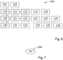
- Fig. 6 schematically illustrates a method 100 of operating an internal combustion engine.
- the internal combustion engine 1 may be an internal combustion engine 1 according to theembodiments explained with reference to Fig. 1 - Fig. 5 above. Therefore below, simultaneous reference is made to Fig. 1 - Fig. 6 , if not indicated otherwise.
- the method 100 is a method of operating an internal combustion engine 1, wherein the method 100 is performed by a control arrangement 21, and wherein the engine 1 comprises a number of cylinders 3, a piston 12 arranged in each cylinder 3 to delimit a combustion chamber 3' inside the cylinder 3, an exhaust system 4 comprising one or more catalytic converters C1, C2 and an exhaust throttle 5 controllable between an open state and a closed state, and a flow control assembly 6 controllable between a first state to provide a nominal amount of gas pumped from the number of cylinders 3 into the exhaust system 4 and a second state to provide a reduced amount of gas pumped from the number of cylinders 3 into the exhaust system 4.
- the method 100 comprises, during idling of the engine 1:
- the method 100 may comprise:
- the method 100 may comprise:
- the method 100 comprises:
- the step of providing 101 the temperature estimate Avg is performed using input from at least two different temperature sensors T1, T2, T3.
- the flow control assembly 6 comprises a cam phaser arrangement 6' controllable to regulate the amount of gas pumped from the number of cylinders 3 into the exhaust system 4, and wherein the steps of controlling 111, 121 the flow control assembly 6 to the first and second states are performed by:
- the step of controlling 121 the flow control assembly 6 to the second state may comprise the steps of:
- step of advancing 124 the control of the exhaust valves 24 may comprise:
- step of retarding 125 the control of the inlet valves 18 may comprise:
- the engine 1 comprises an exhaust gas recirculation loop 7 configured to recirculate exhaust gas from an exhaust outlet 26 of the engine 1 to an air inlet 14 of the engine 1, and wherein the flow control assembly 6 comprises a throttle 27 controllable to regulate the amount of exhaust gas flowing to the exhaust gas recirculation loop 7.
- the steps of controlling 111, 121 the flow control assembly 6 between the first and second states may be performed by:
- the throttle 27 is an EGR-throttle.
- the flow control assembly 6 comprises an air inlet throttle 15 arranged in the air inlet duct 14' of the engine 1. According to such embodiments, the steps of controlling 111, 121 the flow control assembly 6 between the first and second states may be performed by:
- control arrangement 21 may be configured to perform any one of the method steps 101, 103, 110, 111, 112, 113, 116, 120, 121, 122, 123, 124, 124', 125, 125', 126, 130, 131, and 132 of the method 100.
- Fig. 7 illustrates a computer-readable medium 200 comprising instructions which, when executed by a computer, cause the computer to carry out the method 100 according to some embodiments of the present disclosure.
- the computer-readable medium 200 comprises a computer program comprising instructions which, when the program is executed by a computer, cause the computer to carry out the method 100 according to some embodiments.
- the computer may be comprised in the control arrangement 21.
- the method 100 of operating an internal combustion engine 1 may be implemented by programmed instructions.
- These programmed instructions are typically constituted by a computer program, which, when it is executed in the control arrangement 21, ensures that the control arrangement 21 carries out the desired control, such as the method steps 101, 103, 110, 111, 112, 113, 116, 120, 121, 122, 123, 124, 124', 125, 125', 126, 130, 131, and 132 described herein.
- the computer program is usually part of a computer program product 200 which comprises a suitable digital storage medium on which the computer program is stored, such as the computer-readable medium 200 illustrated in Fig. 7 .
- the computer program product may be a computer readable medium 200 and the computer program may be stored in the computer readable medium 200.
- the control arrangement 21 may comprise a computer which may take the form of substantially any suitable type of hardware or hardware/firmware device implemented using processing circuity such as, but not limited to, a processor, Central Processing Unit (CPU), a controller, an arithmetic logic unit (ALU), a digital signal processor, an Application Specific Integrated Circuit (ASIC), a circuit for digital signal processing (digital signal processor, DSP), a microcomputer, a field programmable gate array (FPGA), a System-on-Chip (SoC), a programmable logic unit, a microprocessor, an application-specific integrated circuit, or any other device capable of electronically performing operations in a defined manner or other processing logic that may interpret and execute instructions.
- CPU Central Processing Unit
- ALU arithmetic logic unit
- ASIC Application Specific Integrated Circuit
- DSP Digital signal processor
- microcomputer a field programmable gate array
- FPGA field programmable gate array
- SoC System-on-Chip
- programmable logic unit a microprocessor, an application
- the control arrangement 21 may further comprise a memory unit, wherein the computer may be connected to the memory unit, which may provide the computer with, for example, stored program code and/or stored data which the computer may need to enable it to do calculations.
- the computer may also be adapted to store partial or final results of calculations in the memory unit.
- the memory unit may comprise a physical device utilised to store data or programs, i.e., sequences of instructions, on a temporary or permanent basis. According to some embodiments, the memory unit may comprise integrated circuits comprising silicon-based transistors.
- the memory unit may comprise e.g. a memory card, a flash memory, a USB memory, a hard disc, or another similar volatile or non-volatile storage unit for storing data such as e.g. ROM (Read-Only Memory), PROM (Programmable Read-Only Memory), EPROM (Erasable PROM), EEPROM (Electrically Erasable PROM), etc. in different embodiments.
- the control arrangement 21 is connected to components of the combustion engine 1 for receiving and/or sending input and output signals.
- These input and output signals may comprise waveforms, pulses, or other attributes which the input signal receiving devices can detect as information and which can be converted to signals processable by the control arrangement 21. These signals may then be supplied to the computer.
- One or more output signal sending devices may be arranged to convert calculation results from the computer to output signals for conveying to other parts of the vehicle's control system and/or the component or components for which the signals are intended.
- Each of the connections to the respective components of the combustion engine 1 for receiving and sending input and output signals may take the form of one or more from among a cable, a data bus, e.g. a CAN (controller area network) bus, a MOST (media orientated systems transport) bus or some other bus configuration, or a wireless connection.
- a data bus e.g. a CAN (controller area network) bus, a MOST (media orientated systems transport) bus or some other bus configuration,
- the combustion engine 1 comprises a control arrangement 21 but might alternatively be implemented wholly or partly in two or more control arrangements or two or more control units.
- Control systems in modern vehicles generally comprise a communication bus system consisting of one or more communication buses for connecting a number of electronic control units (ECUs), or controllers, to various components on board the vehicle.
- ECUs electronice control units
- Such a control system may comprise a large number of control units and taking care of a specific function may be shared between two or more of them.
- Vehicles and engines of the type here concerned are therefore often provided with significantly more control arrangements than depicted in Fig. 2 and Fig. 3 , as one skilled in the art will surely appreciate.
- the computer-readable medium 200 may be provided for instance in the form of a data carrier carrying computer program code for performing at least some of the method steps 101, 103, 110, 111, 112, 113, 116, 120, 121, 122, 123, 124, 124', 125, 125', 126, 130, 131, and 132 according to some embodiments when being loaded into one or more computers of the control arrangement 21.
- the data carrier may be, e.g. a CD ROM disc, as is illustrated in Fig.
- the computer-readable medium 200 may be a non-transitory computer-readable medium, such as a tangible electronic, magnetic, optical, infrared, electromagnetic, and/or semiconductor system, apparatus, and/or device.
- the computer-readable medium 200 may furthermore be provided as computer program code on a server and may be downloaded to the control arrangement 21 remotely, e.g., over an Internet or an intranet connection, or via other wired or wireless communication systems.
Landscapes
- Engineering & Computer Science (AREA)
- Chemical & Material Sciences (AREA)
- Combustion & Propulsion (AREA)
- Mechanical Engineering (AREA)
- General Engineering & Computer Science (AREA)
- Chemical Kinetics & Catalysis (AREA)
- Health & Medical Sciences (AREA)
- Toxicology (AREA)
- Output Control And Ontrol Of Special Type Engine (AREA)
Abstract
A method (100) of operating an internal combustion engine (1). The method (100) comprises, during idling of the engine (1) operating (110) the engine (1) in a first mode of operation (m1) by controlling (111) a flow control assembly (6) to provide a nominal amount of gas pumped into an exhaust system (4) and controlling (112) an exhaust throttle (5) to the closed state, operating (120) the engine (1) in a second mode of operation (m2) by controlling (121) the flow control assembly (6) to provide a reduced amount of gas pumped into the exhaust system (4) and controlling (122) the exhaust throttle (5) to an open state, and switching (130) in an alternating manner between the first and second modes of operation (m1, m2). The present disclosure further relates to a control arrangement (21), a computer program, a computer-readable medium (200), an engine (1), and a vehicle (2).
Description
- The present disclosure relates to a method of operating an internal combustion engine. The present disclosure further relates to a control arrangement for an internal combustion engine, a computer program, a computer-readable medium, an engine, and a vehicle.
- Internal combustion engines, such as four-stroke internal combustion engines, comprise one or more cylinders and a piston arranged in each cylinder. The pistons are connected to a crankshaft of the engine and are arranged to reciprocate within the cylinders upon rotation of the crankshaft. The engine usually further comprises one or more inlet valves and one or more outlet valves as well as one or more fuel supply arrangements. The one or more inlet valves and outlet valves are controlled by a respective valve control arrangement usually comprising one or more camshafts rotatably connected to a crankshaft of the engine, via a belt, chain, gears, or similar.
- A four-stroke internal combustion engine completes four separate strokes while turning a crankshaft. A stroke refers to the full travel of the piston along the cylinder, in either direction. The uppermost position of the piston in the cylinder is usually referred to as the top dead centre TDC, and the lowermost position of the piston in the cylinder is usually referred to as the bottom dead centre BDC.
- The strokes are completed in the following order, inlet stroke, compression stroke, expansion stroke and exhaust stroke. During operation of a conventional four-stroke internal combustion engine, the inlet valve control arrangement controls inlet valves of a cylinder to an open state during the inlet stroke of a piston within the cylinder, to allow air, or a mixture of air and fuel, to enter the cylinder. During the compression stroke, all valves should be closed to allow compression of the air, or the mixture of the air and fuel, in the cylinder. If the engine is in a power producing state, fuel in the cylinder is ignited, usually towards the end of the compression stroke, for example by a spark plug or by compression heat in the cylinder.
- The combustion of fuel within the cylinder significantly increases pressure and temperature in the cylinder. The combustion of the fuel usually continues into a significant portion of the subsequent expansion stroke. The increased pressure and temperature in the cylinder obtained by the combustion is partially converted into mechanical work supplied to the crank shaft during the expansion stroke. Obviously, all valves should remain closed during the expansion stroke to allow the increased pressure and temperature to be converted into mechanical work. The expansion stroke is also usually referred to as the combustion stroke, since usually, most of the combustion takes place during the expansion stroke. In the subsequent exhaust stroke, the exhaust valve control arrangement controls exhaust valves of the cylinder to an open state to allow exhaust gases to be expelled out of the cylinder into an exhaust system of the combustion engine.
- Some legislations require heavier vehicles to be provided with an auxiliary braking system in addition to wheel brakes. One type of auxiliary braking system is a so called exhaust brake which comprises an exhaust throttle arranged in the exhaust system of the engine. The exhaust throttle is controllable between an open state and a closed state, wherein the exhaust throttle restricts the flow of gas through the exhaust system to thereby generate a backpressure when controlled to the closed state. The backpressure opposes the upward motion of the pistons when they are moving toward the top dead centre in the exhaust stroke, which thereby increases the braking torque of the engine.
- General problems when designing an internal combustion engine is the emission levels from the engine as well as the fuel consumption of the engine. The emission levels of carbon dioxide CO2 are directly correlated to the fuel consumption of the engine. Moreover, exhausts from an engine can comprise carbon monoxide CO from incomplete combustion, hydrocarbons HC from unburnt fuel, nitrogen oxides NOx from high combustion temperatures, and particulate matter which is usually abbreviated PM and consists mostly of soot/smoke.
- Nitrogen oxides NOx are formed by a reaction between oxygen 02 and nitrogen N upon high temperatures and pressures in a cylinder of an engine. In other words, when the operation of the engine is optimized regarding fuel efficiently, large amounts of nitrogen oxides NOx may be formed. Exhaust gas recirculation (EGR) is an effective strategy to control the NOx emissions from engines. EGR works by recirculating a portion of an engine's exhaust gas back to the engine cylinders. The EGR reduces the formation of NOx through lowering the oxygen concentration in the combustion chamber, as well as through heat absorption, which reduces peak in-cylinder temperatures.
- Due to environmental concerns, almost all vehicles for sale today comprise some sort of exhaust aftertreatment system. Examples are catalytic converters, particulate filters, and Selective catalytic reduction (SCR) arrangements. A selective catalytic reduction arrangement is a means of converting nitrogen oxides, also referred to as NOx with the aid of a catalyst into diatomic nitrogen N2, and water H2O. A gaseous reductant, typically anhydrous ammonia, aqueous ammonia, or urea is added to a stream of exhaust gas and is adsorbed onto a catalytic substrate.
- The conversion efficiency rate of these exhaust aftertreatment systems highly depends on the high temperature of the exhaust gases. Therefore, problems may arise in the converting efficiency of an exhaust aftertreatment system if the engine is operated to generate a low exhaust temperature, especially during cold starts, low engine load conditions, during engine idling, and similar operating conditions. Therefore, at certain times and/or conditions, it can be desired to operate the engine to increase the exhaust temperature even if it has a negative impact on the fuel consumption of the engine.
- Engine idling refers to the operation of an internal combustion engine when it is running but not actively engaged in performing any useful work. During engine idling, the engine is operated to run at a low speed, typically around 600 to 1000 revolutions per minute (RPM), to maintain basic functions such as powering the vehicle's electrical systems, operating air conditioning or heating, and allowing for a quick restart when necessary.
- Upcoming emission regulations require exhaust aftertreatment systems to be kept warm even during engine idling to be able to fulfil the maximum permitted NOx emission levels. One way to increase the temperature of an exhaust aftertreatment system is to inject more fuel. However, as a consequence, the engine speed will increase unless other measures are performed to restrict the engine speed, such as by controlling an exhaust throttle to a closed state. Increasing an injected fuel amount and closing an exhaust throttle is an efficient means of raising the temperature of an exhaust aftertreatment system to thereby maintain a conversion efficiency thereof. However, it will also cause a significant increase in fuel consumption.
- For minimum fuel consumption, the exhaust flow to be heated should be minimized. However, if the exhaust flow is too small, the throttling of the exhaust gas by the exhaust throttle is not enough for keeping engine speed from rising at sufficient fuel quantity for the desired temperature. Moreover, if braked by other means, the engine would still have combustion stability issues at small exhaust flow and low fuel injection levels.
- It is an object of the present invention to overcome, or at least alleviate, at least some of the above-mentioned problems and drawbacks.
- According to a first aspect of the invention, the object is achieved by a method of operating an internal combustion engine, wherein the method is performed by a control arrangement, and wherein the engine comprises a number of cylinders, a piston arranged in each cylinder to delimit a combustion chamber inside the cylinder, an exhaust system comprising one or more catalytic converters and an exhaust throttle controllable between an open state and a closed state, and a flow control assembly controllable between a first state to provide a nominal amount of gas pumped from the number of cylinders into the exhaust system and a second state to provide a reduced amount of gas pumped from the number of cylinders into the exhaust system. The method comprises, during idling of the engine:
- operating the engine in a first mode of operation by controlling the flow control assembly to the first state and controlling the exhaust throttle to the closed state,
- operating the engine in a second mode of operation by controlling the flow control assembly to the second state and controlling the exhaust throttle to the open state, and
- switching in an alternating manner between the first and second modes of operation.
- Since the method comprises the step of switching in an alternating manner between the first and second modes of operation, a method is provided having conditions for maintaining a temperature of the one or more catalytic converters above a lower threshold temperature while minimizing the fuel consumption of the engine during idling of the engine.
- This is because the method comprises the steps of controlling the flow control assembly to provide the nominal amount of gas pumped from the number of cylinders into the exhaust system and controlling the exhaust throttle to the closed state when operating the engine in the first mode of operation. Accordingly, the one or more catalytic converters will be heated in an efficient manner when the engine is operated in the first mode of operation. Therefore, the first mode of operation, as referred to herein, may also be referred to as a heating mode.
- Moreover, as indicated above, the method comprises the steps of controlling the flow control assembly to provide the reduced amount of gas pumped from the number of cylinders into the exhaust system and controlling the exhaust throttle to the open state when operating the engine in the second mode of operation. The reduced amount of gas pumped from the number of cylinders into the exhaust system results in a low cooling rate of the one or more catalytic converters and the controlling of the exhaust throttle to the open state can ensure combustion stability despite a low flow of gas through the engine and a low fuel injection rate in the second mode of operation. Therefore, the second mode of operation, as referred to herein, may also be referred to as a temperature saving mode.
- Accordingly, by switching in an alternating manner between the first and second modes of operation, a method is provided having conditions for maintaining a temperature of the one or more catalytic converters above a lower threshold temperature while minimizing the fuel consumption of the engine during idling of the engine.
- Since the temperature of the one or more catalytic converters can be maintained above a lower threshold temperature, the conversion efficiency rate thereof can be maintained while ensuring a low fuel consumption of the engine during idling. In other words, a method is provided having conditions for meeting upcoming emission legislations while minimizing the fuel consumption of the engine.
- Accordingly, a method is provided overcoming, or at least alleviating, at least some of the above-mentioned problems and drawbacks. As a result, the above-mentioned object is achieved.
- Optionally, the method comprises:
- providing a temperature estimate of at least one of the one or more catalytic converters, and
- switching from the first mode of operation to the second mode of operation when the temperature estimate rises above an upper threshold temperature.
- Thereby, it can be ensured that a low cooling rate of the one or more catalytic converters is obtained when the temperature estimate rises above the upper threshold temperature and that the fuel consumption of the engine is minimized in such situations.
- Optionally, the method comprises:
- providing a temperature estimate of at least one of the one or more catalytic converters, and
- switching from the second mode of operation to the first mode of operation when the temperature estimate declines below a lower threshold temperature.
- Thereby, it can be ensured that the one or more catalytic converters is/are heated in an efficient manner when the temperature estimate declines below the lower threshold temperature. In other words, in this manner, it can be ensured that a high conversion efficiency rate of the one or more catalytic converters is maintained during engine idling of the engine.
- Optionally, the method comprises:
- providing a temperature estimate of at least one of the one or more catalytic converters, and upon receipt of an idling request:
- selecting between initiating idling of the engine in the first mode of operation or in the second mode of operation based on the temperature estimate.
- Thereby, a method is provided in which engine idling can be initiated in an optimal manner regarding fuel consumption and conversion efficiency rate of the one or more catalytic converters. This is because engine idling can be initiated in the first mode of operation if the temperature estimate is below a threshold temperature so as to efficiently heat the one or more catalytic converters and can be initiated in the second mode of operation if the temperature estimate is above a threshold temperature so as to efficiently maintain the temperature of the one or more catalytic converters.
- Optionally, the step of providing the temperature estimate is performed using input from at least two different temperature sensors.
- Thereby, a more robust and redundant switching can be performed between the first and second modes of operation. In other words, due to these features, further improved conditions are provided for maintaining a temperature of the one or more catalytic converters above a lower threshold temperature while minimizing the fuel consumption of the engine during idling.
- Optionally, the flow control assembly comprises a cam phaser arrangement controllable to regulate the amount of gas pumped from the number of cylinders into the exhaust system, and wherein the steps of controlling the flow control assembly to the first and second states are performed by:
- controlling the cam phaser arrangement to phase shift control of at least one of inlet valves and exhaust valves of the engine.
- Thereby, the amount of gas pumped from the number of cylinders into the exhaust system can be controlled in an efficient manner.
- Optionally, the step of controlling the flow control assembly to the second state comprises the steps of:
- advancing control of exhaust valves of the engine, and
- retarding control of inlet valves of the engine.
- Thereby, the amount of gas pumped from the number of cylinders into the exhaust system can be controlled in an efficient manner while ensuring combustion stability and a low fuel consumption of the engine.
- Optionally, the step of advancing the control of the exhaust valves comprises:
- advancing the control of the exhaust valves a number of crank angle degrees being within the range of 20 - 85, or within the range of 50 - 70.
- Thereby, it can be ensured that a low amount of gas is pumped from the number of cylinders into the exhaust system so as to efficiently maintain a temperature of the one or more catalytic converters while ensuring combustion stability and a low fuel consumption of the engine.
- Optionally, the step of retarding the control of the inlet valves comprises:
- retarding the control of the inlet valves a number of crank angle degrees being within the range of 20 - 85, or within the range of 45 - 60.
- Thereby, it can be ensured that a low amount of gas is pumped from the number of cylinders into the exhaust system so as to efficiently maintain a temperature of the one or more catalytic converters while ensuring combustion stability and a low fuel consumption of the engine.
- Optionally, the engine comprises an exhaust gas recirculation loop configured to recirculate exhaust gas from an exhaust outlet of the engine to an air inlet of the engine, and wherein the flow control assembly comprises a throttle controllable to regulate the amount of exhaust gas flowing to the exhaust gas recirculation loop, and wherein the steps of controlling the flow control assembly between the first and second states is performed by:
- controlling an opening degree of the throttle.
- Thereby, the amount of gas pumped from the number of cylinders into the exhaust system can be controlled in a simple and efficient manner.
- According to a second aspect of the invention, the object is achieved by a control arrangement for an internal combustion engine, and wherein the engine comprises a number of cylinders, a piston arranged in each cylinder to delimit a combustion chamber inside the cylinder, an exhaust system comprising one or more catalytic converters and an exhaust throttle controllable between an open state and a closed state, and a flow control assembly controllable between a first state to provide a nominal amount of gas pumped from the number of cylinders into the exhaust system and a second state to provide a reduced amount of gas pumped from the number of cylinders into the exhaust system. The control arrangement is configured to, during idling of the engine:
- operate the engine in a first mode of operation by controlling the flow control assembly to the first state and controlling the exhaust throttle to the closed state,
- operate the engine in a second mode of operation by controlling the flow control assembly to the second state and controlling the exhaust throttle to the open state, and
- switch in an alternating manner between the first and second modes of operation.
- Since the control arrangement is configured to switch in an alternating manner between the first and second modes of operation, a control arrangement is provided having conditions for maintaining a temperature of the one or more catalytic converters above a lower threshold temperature while minimizing the fuel consumption of the engine during idling of the engine.
- This is because the control arrangement is configured to control the flow control assembly to provide the nominal amount of gas pumped from the number of cylinders into the exhaust system and control the exhaust throttle to the closed state when operating the engine in the first mode of operation. Accordingly, the one or more catalytic converters will be heated in an efficient manner when the engine is operated in the first mode of operation by the control arrangement. Therefore, the first mode of operation, as referred to herein, may also be referred to as a heating mode.
- Moreover, as indicated above, the control arrangement is configured to control the flow control assembly to provide the reduced amount of gas pumped from the number of cylinders into the exhaust system and control the exhaust throttle to the open state when operating the engine in the second mode of operation. The reduced amount of gas pumped from the number of cylinders into the exhaust system results in a low cooling rate of the one or more catalytic converters and the control of the exhaust throttle to the open state can ensure combustion stability despite a low flow of gas through the engine and a low fuel injection rate in the second mode of operation. Therefore, the second mode of operation, as referred to herein, may also be referred to as a temperature saving mode.
- Accordingly, by switching in an alternating manner between the first and second modes of operation, the control performed by the control arrangement can maintain a temperature of the one or more catalytic converters above a lower threshold temperature while minimizing the fuel consumption of the engine during idling.
- Since the temperature of the one or more catalytic converters can be maintained above a lower threshold temperature, the conversion efficiency rate thereof can be maintained while ensuring a low fuel consumption of the engine during idling. In other words, a control arrangement is provided having conditions for meeting upcoming emission legislations while minimizing the fuel consumption of the engine.
- Accordingly, a control arrangement is provided overcoming, or at least alleviating, at least some of the above-mentioned problems and drawbacks. As a result, the above-mentioned object is achieved.
- According to a third aspect of the invention, the object is achieved by a computer program comprising instructions to cause the control arrangement according to the second aspect of the invention to execute the steps of the method according to some embodiments of the first aspect of the invention. Since the computer program comprises instructions to cause the control arrangement to carry out the method according to some embodiments described herein, a computer program is provided which provides conditions for overcoming, or at least alleviating, at least some of the above-mentioned drawbacks. As a result, the above-mentioned object is achieved.
- According to a fourth aspect of the invention, the object is achieved by a computer-readable medium having stored thereon the computer program according to the third aspect of the invention. Since the computer-readable medium comprises instructions to cause the control arrangement to carry out the method according to some embodiments described herein, a computer-readable medium is provided which provides conditions for overcoming, or at least alleviating, at least some of the above-mentioned drawbacks. As a result, the above-mentioned object is achieved.
- According to a fifth aspect of the invention, the object is achieved by an engine comprising a number of cylinders, a piston arranged in each cylinder to delimit a combustion chamber inside the cylinder, an exhaust system comprising one or more catalytic converters and an exhaust throttle controllable between an open state and a closed state, and a flow control assembly controllable between a first state to provide a nominal amount of gas pumped from the number of cylinders into the exhaust system and a second state to provide a reduced amount of gas pumped from the number of cylinders into the exhaust system, and a control arrangement configured to, during idling of the engine:
- operate the engine in a first mode of operation by controlling the flow control assembly to the first state and controlling the exhaust throttle to the closed state,
- operate the engine in a second mode of operation by controlling the flow control assembly to the second state and controlling the exhaust throttle to the open state, and
- switch in an alternating manner between the first and second modes of operation.
- Since the control arrangement of the engine is configured to switch in an alternating manner between the first and second modes of operation, an engine is provided having conditions for maintaining a temperature of the one or more catalytic converters above a lower threshold temperature while minimizing the fuel consumption during idling.
- This is because the control arrangement of the engine is configured to control the flow control assembly to provide the nominal amount of gas pumped from the number of cylinders into the exhaust system and control the exhaust throttle to the closed state when operating the engine in the first mode of operation. Accordingly, the one or more catalytic converters will be heated in an efficient manner when the engine is operated in the first mode of operation by the control arrangement of the engine.
- Moreover, as indicated above, the control arrangement of the engine is configured to control the flow control assembly to provide the reduced amount of gas pumped from the number of cylinders into the exhaust system and control the exhaust throttle to the open state when operating the engine in the second mode of operation. The reduced amount of gas pumped from the number of cylinders into the exhaust system results in a low cooling rate of the one or more catalytic converters and the control of the exhaust throttle to the open state can ensure combustion stability despite a low flow of gas through the engine and a low fuel injection rate in the second mode of operation.
- Accordingly, by switching in an alternating manner between the first and second modes of operation, the control performed by the control arrangement of the engine can maintain a temperature of the one or more catalytic converters above a lower threshold temperature while minimizing the fuel consumption of the engine during idling.
- Since the temperature of the one or more catalytic converters can be maintained above a lower threshold temperature, the conversion efficiency rate thereof can be maintained while ensuring a low fuel consumption of the engine during idling. In other words, a control arrangement is provided having conditions for meeting upcoming emission legislations while minimizing the fuel consumption of the engine.
- Accordingly, an engine is provided overcoming, or at least alleviating, at least some of the above-mentioned problems and drawbacks. As a result, the above-mentioned object is achieved.
- According to a sixth aspect of the invention, the object is achieved by a vehicle comprising an engine according to the fifth aspect of the invention. Since the vehicle comprises an engine according to the fifth aspect of the invention, a vehicle is provided overcoming, or at least alleviating, at least some of the above-mentioned problems and drawbacks. As a result, the above-mentioned object is achieved.
- Further features of, and advantages with, the present invention will become apparent when studying the appended claims and the following detailed description.
- Various aspects of the invention, including its particular features and advantages, will be readily understood from the example embodiments discussed in the following detailed description and the accompanying drawings, in which:
-
Fig. 1 schematically illustrates a vehicle according to some embodiments, -
Fig. 2 schematically illustrates an internal combustion engine of the vehicle illustrated inFig. 1 , -
Fig. 3 schematically illustrates a cross sectional view of the internal combustion engine illustrated inFig. 2 , -
Fig. 4a and Fig. 4b illustrate valve lift events in different operational states of a cam phaser arrangement of the engine illustrated inFig. 2 andFig. 3 , -
Fig. 5 illustrates an upper graph showing temperature data as a function of time from a first, a second, and a third temperature sensor of the engine illustrated inFig. 2 andFig. 3 , and a lower graph showing a current operational mode of the engine illustrated inFig. 2 andFig. 3 , -
Fig. 6 schematically illustrates a method of operating an internal combustion engine, and -
Fig. 7 illustrates a computer-readable medium. - Aspects of the present invention will now be described more fully. Like reference signs refer to like elements throughout. Well-known functions or constructions will not necessarily be described in detail for brevity and/or clarity.
-
Fig. 1 schematically illustrates avehicle 2 according to some embodiments of the present disclosure. According to the illustrated embodiments, thevehicle 2 is a truck, i.e. a type of heavy road vehicle, as well as a type of heavy commercial vehicle. According to further embodiments, thevehicle 2, as referred to herein, may be another type of heavy or lighter type of manned or unmanned vehicle for land based propulsion such as a lorry, a bus, a construction vehicle, a tractor, a car, or the like. - The
vehicle 2 comprises aninternal combustion engine 1. According to the illustrated embodiments, theinternal combustion engine 1 is configured to provide motive power to thevehicle 2 viawheels 47 of thevehicle 2. Thevehicle 2 may comprise one or more electric propulsion motors in addition to theinternal combustion engine 1 for providing motive power to thevehicle 2. Thus, thevehicle 2 may comprise a so called hybrid electric powertrain comprising one or more electric propulsion motors in addition to theinternal combustion engine 1 for providing motive power to thevehicle 2. - For reasons of brevity and clarity, the
internal combustion engine 1 is in some places herein simply referred to as "theengine 1". -
Fig. 2 schematically illustrates theinternal combustion engine 1 of thevehicle 2 illustrated inFig. 1 .Cylinders 3 of theengine 1 are schematically indicated inFig. 2 . According to the illustrated embodiments, theengine 1 comprises fourcylinders 3 arranged in one row. Theengine 1 according to the illustrated embodiments may therefore be referred to an inline-four engine. However, according to further embodiments, theengine 1, as referred to herein, may comprise another number ofcylinders 3. Moreover, thecylinders 3 of theengine 1 may be arranged in another configuration than in one row, such as in two or more rows. - According to the illustrated embodiments, the
internal combustion engine 1 is a diesel engine, i.e. a type of compression ignition engine. Theinternal combustion engine 1 may thus be configured to operate on diesel or a diesel-like fuel, such as biodiesel, biomass to liquid (BTL), or gas to liquid (GTL) diesel. Diesel-like fuels, such as biodiesel, can be obtained from renewable sources such as vegetable oil which mainly comprises fatty acid methyl esters (FAME). Diesel-like fuels can be produced from many types of oils, such as rapeseed oil (rapeseed methyl ester, RME) and soybean oil (soy methyl ester, SME). - According to further embodiments, the
internal combustion engine 1, as referred to herein, may an Otto engine with a spark-ignition device, wherein the Otto engine may be configured to run on petrol, alcohol, similar volatile fuels, or combinations thereof. Alcohol, such as ethanol, can be derived from renewable biomass. According to embodiments herein, theinternal combustion engine 1 is a four-strokeinternal combustion engine 1. - The
engine 1 comprises anair inlet 14 and anexhaust outlet 26. Theengine 1 further comprises anair inlet duct 14' connected to theair inlet 14 and anexhaust system 4 connected to exhaustoutlet 26 of theengine 1. Theexhaust system 4 is configured to conduct exhaust gas from theexhaust outlet 26 to the surroundings. - According to the illustrated embodiments, the
engine 1 further comprises aturbocharger 11. Theturbocharger 11 comprises a turbine 11' driven by exhaust gas flowing out from theengine 1 via theexhaust outlet 26. Moreover, theturbocharger 11 comprises acompressor wheel 11" connected to the turbine 11'. Thecompressor wheel 11" is configured to compress air from anair filter assembly 19 of theengine 1 to theair inlet 14 of theengine 1. Thecompressor wheel 11" may be connected to the turbine 11' via a shaft. Moreover, according to the illustrated embodiments, theengine 1 comprises acharge air cooler 17. Thecharge air cooler 17 is configured to cool the air compressed by thecompressor wheel 11" before the air is conducted to theair inlet 14 of theengine 1. - According to further embodiments, the
engine 1 may lack a turbocharger and/or may comprise one or more other types of supercharger devices, such as one or more compressors. Moreover, according to some embodiments, theengine 1 may comprise two or more turbochargers, wherein the two or more turbochargers may be arranged in parallel or on series. - According to the illustrated embodiments, the
exhaust system 4 comprises two catalytic converters C1, C2 and a diesel particulate filter P1. According to further embodiments, theexhaust system 4 may comprise another number of catalytic converters, such as one, three, four, or the like. - In more detail, according to the illustrated embodiments, the
exhaust system 4 comprises a first Selective Catalytic Reduction (SCR) catalyst C1 and a second Selective Catalytic Reduction (SCR) catalyst C2, wherein the second Selective Catalytic Reduction (SCR) catalyst C2 is arranged downstream of the first Selective Catalytic Reduction (SCR) catalyst C1 in theexhaust system 4. Moreover, according to the illustrated embodiments, each of the first and second Selective Catalytic Reduction (SCR) catalysts C1, C2 comprises a respective ammonia slip catalyst A1, A2. According to the illustrated embodiments, the diesel particulate filter P1 is positioned between the first and second Selective Catalytic Reduction (SCR) catalysts C1, C2. - The
exhaust system 4 further comprises a first reductant dosing unit D1 and a second reductant dosing unit D2. The first reductant dosing unit D1 is arranged upstream of a catalytic substrate of the first Selective Catalytic Reduction (SCR) catalyst C1 and the second reductant dosing unit D2 is arranged upstream of a catalytic substrate of the second a Selective Catalytic Reduction (SCR) catalyst C2. Each of the first and second reductant dosing units D1, D2 is configured to introduce a reductant, such as an aqueous solution of urea known as Diesel Exhaust Fluid (DEF), into the exhaust stream. When the exhaust gases pass through a catalytic substrate of the respective SCR catalyst C1, C2, the urea reacts with the NOx, converting it into nitrogen (N2) and water (H2O). - In some cases, a small amount of unreacted ammonia, known as "ammonia slip," may escape a SCR catalyst C1, C2 without undergoing the desired reaction. To address this issue, the ammonia slip catalysts A1, A2 are added downstream of the respective SCR catalyst C1, C2. The ammonia slip catalysts A1, A2 are designed to promote a secondary reaction, where the remaining ammonia in the exhaust gas is further oxidized and converted into nitrogen and water vapor. By incorporating the ammonia slip catalysts A1, A2, the overall efficiency of the SCR system is improved, ensuring that a minimal amount of ammonia is emitted into the environment.
- An ammonia slip catalyst A1, A2 typically comprises a high-surface-area catalyst that facilitates the oxidation of ammonia. It operates under specific temperature and operating conditions to ensure optimal performance. The presence of the ammonia slip catalysts A1, A2 helps to meet strict emission standards and ensures that the SCR system operates efficiently, minimizing both nitrogen oxide (NOx) and ammonia (NH3) emissions.
- The
exhaust system 4 further comprises a first temperature sensor T1, a second temperature sensor T2, and a third temperature sensor T3. The first temperature sensor T1 is configured to provide data representative of the temperature of exhaust gas flowing into the first Selective Catalytic Reduction (SCR) catalyst C1. The second temperature sensor T2 is configured to provide data representative of the temperature of exhaust gas flowing into the diesel particulate filter P1. The third temperature sensor T3 is configured to provide data representative of the temperature of exhaust gas flowing into the second Selective Catalytic Reduction (SCR) catalyst C2. According to the illustrated embodiments, the first temperature sensor T1 is positioned at a gas inlet of the first Selective Catalytic Reduction (SCR) catalyst C1, the second temperature sensor T2 is positioned at a gas inlet of the diesel particulate filter P1, and the third temperature sensor T3 is positioned at a gas inlet of the second Selective Catalytic Reduction (SCR) catalyst C2. According to further embodiments, theexhaust system 4 may comprise another number of temperature sensors which may be positioned in another manner than described above, and in another manner than what is depicted inFig. 2 . - The
exhaust system 4 further comprises anexhaust throttle 5. Theexhaust throttle 5 is controllable between an open state and a closed state. Theexhaust throttle 5 is configured to provide at least substantially no restriction of exhaust flow through theexhaust throttle 5 when theexhaust throttle 5 is in the open state. Theexhaust throttle 5 is configured to provide a restriction of the flow of exhaust gas through theexhaust throttle 5 when theexhaust throttle 5 is in the closed state. The closed state of theexhaust throttle 5, as referred to herein, may also be referred to as an at least partially closed state, a partially closed state, or the like. - The
exhaust throttle 5 may for example be controlled to the closed state when wanting to provide additional braking force onto avehicle 2 comprising theengine 1. The additional braking force is provided due to an increased force on pistons of theengine 1 for pumping gas out from thecylinders 3 in exhaust strokes of thecylinders 3 when theexhaust throttle 5 is in the closed state. According to the illustrated embodiments, theexhaust throttle 5 is positioned between the turbine 11' of theturbocharger 11 and the first Selective Catalytic Reduction (SCR) catalyst C1. - The
engine 1 further comprises aflow control assembly 6. Theflow control assembly 6 is controllable between a first state to provide a nominal amount of gas pumped from the number ofcylinders 3 into theexhaust system 4 and a second state to provide a reduced amount of gas pumped from the number ofcylinders 3 into theexhaust system 4. The features, functions, and advantages of theflow control assembly 6 are explained in more detail below. - Moreover, as indicated in
Fig. 2 , theengine 1 comprises acontrol arrangement 21. According to the illustrated embodiments, thecontrol arrangement 21 is operably connected to theflow control assembly 6, theexhaust throttle 5, the first temperature sensor T1, the first reductant dosing unit D1, the second temperature sensor T2, the third temperature sensor T3, and the second reductant dosing unit D2. -
Fig. 3 schematically illustrates a cross sectional view of theinternal combustion engine 1 illustrated inFig. 2 . InFig. 3 , the cross section is made in a plane comprising a centre axis of one of thecylinders 3 of theengine 1. Theengine 1 comprises at least onecylinder 3 and a piston 12 arranged in eachcylinder 3. The piston 12 delimits a combustion chamber 3' inside thecylinder 3 and is connected via a connectingrod 13 to acrankshaft 16, which at rotation moves the piston 12 forwards and backwards in thecylinder 3, between a top dead centre (TDC) and a bottom dead centre (BDC). InFig. 3 , the piston 12 is illustrated in a region of the top dead centre. - Moreover, in
Fig. 3 , theair inlet 14 and theexhaust outlet 26 of theengine 1 are indicated. Theengine 1 further comprises at least oneinlet valve 18 arranged in eachcylinder 3, which at least oneinlet valve 18 is connected with theair inlet 14. Theengine 1 further comprises an inletvalve control arrangement 22 configured to control eachinlet valve 18 on the basis of a rotational position of thecrankshaft 16. Theengine 1 further comprises at least oneexhaust valve 24 arranged in eachcylinder 3, which at least oneexhaust valve 24 is connected with anexhaust outlet 26 of theengine 1. - The
engine 1 further comprises an exhaustvalve control arrangement 28 configured to control eachexhaust valve 24 on the basis of the rotational position of thecrankshaft 16. InFig. 3 , theinlet valve 18 and theexhaust valve 24 are illustrated in a respective fully closed position. In a fully closed position, eachvalve cylinder 3 and therespective air inlet 14 and theexhaust outlet 26. - The inlet
valve control arrangement 22 is arranged to control the at least oneinlet valve 18 between the fully closed position and an open position by displacing the at least oneinlet valve 18 in a direction into thecylinder 3. A fluid connection is thereby opened between theair inlet 14 and thecylinder 3. Likewise, the exhaustvalve control arrangement 28 is arranged to control the at least oneexhaust valve 24 between the fully closed position to an open position by displacing the at least oneexhaust valve 24 in a direction into thecylinder 3. Thereby, a fluid connection is opened between thecylinder 3 and theexhaust outlet 26. Upon displacement of avalve valve - According to the illustrated embodiments, the engine comprises one fuel injector i1 per
cylinder 3 wherein each fuel injector i1 is configured to inject fuel directly into acylinder 3 of theinternal combustion engine 1. According to further embodiments, theinternal combustion engine 1 may comprise another number of fuel injectors i1 percylinder 3. Moreover, according to some embodiments, theinternal combustion engine 1 may comprise one or more fuel injectors configured to inject fuel into an air inlet of thecombustion engine 1 as an alternative to fuel injectors i1 configured to inject fuel into thecylinders 3 or in addition to the fuel injectors i1 configured to inject fuel into thecylinders 3. According to the illustrated embodiments, thecontrol arrangement 21 of theengine 1 is operably connected to each fuel injector i1 and is configured to control the operation thereof. - The exhaust
valve control arrangement 28 and the inletvalve control arrangement 22 may each comprise one ormore camshafts crankshaft 16 of theengine 1. Moreover, the exhaustvalve control arrangement 28 and the inletvalve control arrangement 22 may each comprise one or more arrangements, such asrocker arms camshafts valves valves respective camshaft - According to further embodiments, the cam lobes of the
camshafts engine 1 may be arranged to displacevalves valves respective camshaft valve control arrangement 28 and/or the inletvalve control arrangement 22 may according to further embodiments comprise electric, pneumatic, or hydraulic actuators arranged to control valves based on the rotational position of thecrankshaft 16. The rotational position of thecrankshaft 16 may be obtained using acrank angle sensor 29. - In the following, some features, functions, and advantages of the
flow control assembly 6 are further explained with simultaneous reference toFig. 1 - Fig. 3 . As mentioned, theflow control assembly 6 is controllable between a first state to provide a nominal amount of gas pumped from the number ofcylinders 3 into theexhaust system 4 and a second state to provide a reduced amount of gas pumped from the number ofcylinders 3 into theexhaust system 4. - As indicated in
Fig. 2 , according to the illustrated embodiments, theflow control assembly 6 comprises an Exhaust Gas Recirculation (EGR)system 6". The Exhaust Gas Recirculation (EGR)system 6" comprises an exhaustgas recirculation loop 7 configured to recirculate exhaust gas from anexhaust outlet 26 of theengine 1 to anair inlet 14 of theengine 1. Moreover, the Exhaust Gas Recirculation (EGR)system 6" of theflow control assembly 6 comprises athrottle 27 controllable to regulate the amount of exhaust gas flowing to the exhaustgas recirculation loop 7. According to the illustrated embodiments, thethrottle 27 is an EGR-throttle arranged in the exhaustgas recirculation loop 7. - As seen in
Fig. 2 , according to the illustrated embodiments, thecontrol arrangement 21 is operably connected to thethrottle 27 and is configured to control an opening degree of thethrottle 27 so as to regulate the amount of gas pumped from the number ofcylinders 3 into theexhaust system 4. According to the illustrated embodiments, thecontrol arrangement 21 is configured to decrease an opening degree of thethrottle 27 upon switching to a first state and is configured to increase the opening degree of thethrottle 27 upon switching to a second state. - If the
throttle 27 is controlled towards a more open state, i.e., if the opening degree of thethrottle 27 is increased, more gas will be conducted through the exhaustgas recirculation loop 7 and consequently less gas will be pumped from the number ofcylinders 3 into theexhaust system 4. Moreover, if thethrottle 27 is controlled towards a more closed state, i.e., if the opening degree of thethrottle 27 is decreased, less gas will be conducted through the exhaustgas recirculation loop 7 and more gas will be pumped from the number ofcylinders 3 into theexhaust system 4. In other words, a higher proportion of gas flowing through the exhaustgas recirculation loop 7 leads to a reduced amount of gas pumped from the number ofcylinders 3 into theexhaust system 4 and vice versa. These and further aspects of the control performed by thecontrol arrangement 21 are explained in greater detail below. - Moreover, according to the illustrated embodiments, the
flow control assembly 6 comprises anair inlet throttle 15 arranged in theair inlet duct 14' of theengine 1. As seen inFig. 2 , according to the illustrated embodiments, thecontrol arrangement 21 is operably connected to theair inlet throttle 15 and is configured to control an opening degree of theair inlet throttle 15 so as to regulate the amount of gas pumped from the number ofcylinders 3 into theexhaust system 4. According to the illustrated embodiments, thecontrol arrangement 21 is configured to increase an opening degree of theair inlet throttle 15 upon switching to the first state and is configured to decrease the opening degree of theair inlet throttle 15 upon switching to the second state. - If the
air inlet throttle 15 is controlled towards a more closed state, i.e., if the opening degree of theair inlet throttle 15 is decreased, more gas will be conducted through the exhaustgas recirculation loop 7 and consequently less gas will be pumped from the number ofcylinders 3 into theexhaust system 4. Moreover, if theair inlet throttle 15 is controlled towards a more open state, i.e., if the opening degree of theair inlet throttle 15 is increased, less gas will be conducted through the exhaustgas recirculation loop 7 and more gas will be pumped from the number ofcylinders 3 into theexhaust system 4. In other words, a higher proportion of gas flowing through the exhaustgas recirculation loop 7 leads to a reduced amount of gas pumped from the number ofcylinders 3 into theexhaust system 4 and vice versa. These and further aspects of the control performed by thecontrol arrangement 21 are explained in greater detail below. - The exhaust
gas recirculation loop 7 may as an alternative, or in addition, comprise one or more other types of throttles controllable by thecontrol arrangement 21 so as to regulate the amount of gas pumped from the number ofcylinders 3 into theexhaust system 4. Moreover, the exhaustgas recirculation loop 7 may comprise one or more further arrangements or systems, such as an EGR cooler. - Furthermore, as is indicated in
Fig. 2 , according to the illustrated embodiments, theflow control assembly 6 comprises a cam phaser arrangement 6'. As is explained in the following, the cam phaser arrangement 6' is controllable to regulate the amount of gas pumped from the number ofcylinders 3 into theexhaust system 4. According to the illustrated embodiments, theflow control assembly 6 of theengine 1 comprises the Exhaust Gas Recirculation (EGR)system 6" as well as the cam phaser arrangement 6'. According to further embodiments, theflow control assembly 6 of theengine 1 may comprise only one of the Exhaust Gas Recirculation (EGR)system 6" and the cam phaser arrangement 6' for regulating the amount of gas pumped from the number ofcylinders 3 into theexhaust system 4. - The cam phaser arrangement 6' of the
flow control assembly 6 is also indicated inFig. 3 . According to the illustrated embodiments, the cam phaser arrangement 6' comprises an exhaust valve phase-shiftingdevice 30 configured to phase-shift control of the at least oneexhaust valve 24 in relation to thecrankshaft 16. Moreover, according to the illustrated embodiments, the cam phaser arrangement 6' comprises an inlet valve phase-shiftingdevice 32 configured to phase-shift control of the at least oneinlet valve 18 in relation to thecrankshaft 16. - The exhaust valve phase-shifting
device 30 and the inlet valve phase-shiftingdevice 32 may each comprise a hydraulic arrangement, for example using engine oil as hydraulic fluid, to phase-shift control of thevalves crankshaft 16. Such hydraulic arrangement may form part of a belt pulley, gear wheel, sprocket, or the like (not illustrated) arranged to transfer rotation from thecrankshaft 16 to acamshaft valve control arrangement 28 and/or the inletvalve control arrangement 22. The hydraulic arrangement may be arranged to regulate an angular relationship between a first portion of the belt pulley, gear wheel, sprocket, or the like, being connected to thecrankshaft 16, and a second portion of the belt pulley, gear wheel, sprocket, or the like, being connected to thecamshaft inlet valve 18 and/or the at least oneexhaust valve 24. In embodiments wherein the exhaustvalve control arrangement 28 and/or the inletvalve control arrangement 22 comprises electric, pneumatic, or hydraulic actuators, the phase-shift of control of the at least oneinlet valve 18 and/or the at least oneexhaust valve 24 may be performed in another manner, for example by an electronic phase-shift of control. - According to the illustrated embodiments, the
control arrangement 21 of theengine 1 is operably connected to each of the exhaust valve phase-shiftingdevice 30 and the inlet valve phase-shiftingdevice 32 and is configured to control operation thereof. Thecontrol arrangement 21 may be operably connected to one or more further components and systems of theengine 1, such as the inletvalve control arrangement 22 and the exhaustvalve control arrangement 28 and may be configured to control operation thereof. Furthermore, thecontrol arrangement 21 may be connected to a number of different sensors to obtain signals therefrom. Examples are sensors arranged to sense exhaust pressure, charge air temperature, mass airflow, throttle position, engine speed, engine load, absolute pressure in an inlet manifold, rotational position of thecrank shaft 16, and the like. -
Fig. 4a and Fig. 4b illustratevalve lift events engine 1 illustrated inFig. 2 andFig. 3 . Therefore, below, reference is made to theFig. 1 - Fig. 4b , if not indicated otherwise. The curves illustrated inFig. 4a and Fig. 4b illustrate valve lift events performed during two revolutions of thecrank shaft 16, i.e. during all four strokes of the four-strokeinternal combustion engine 1. In these figures, the strokes are illustrated in the following order:compression stroke 41,expansion stroke 42,exhaust stroke 43 andinlet stroke 44. -
Fig. 4a illustratesvalve lift events 51 of the at least oneinlet valve 18, andvalve lift events 52 of the at least oneexhaust valve 24, obtained when the cam phaser arrangement 6' is in a first state. As indicated, during thecompression stroke 41 and theexpansion stroke 42, the at least oneinlet valve 18 and the at least oneexhaust valve 24 are closed. When the piston reaches the bottom dead centre BDC at the end of theexpansion stroke 42, the exhaustvalve control arrangement 28 controls the at least oneexhaust valve 24 to an open position to allow exhaust gases to be expelled from thecylinder 3 to theexhaust outlet 26 during theexhaust stroke 43. In the transition area between theexhaust stroke 43 and theinlet stroke 44, the exhaustvalve control arrangement 28 controls the at least oneexhaust valve 24 to a closed position. - Moreover, in the transition area between the
exhaust stroke 43 and theinlet stroke 44, the inletvalve control arrangement 22 controls the at least oneinlet valve 18 to an open position to allow air, or an air/fuel mixture, to enter thecylinder 3 during theinlet stroke 44. Towards the end of theinlet stroke 44, the inletvalve control arrangement 22 controls the at least oneinlet valve 18 to a closed position to allow compression of the air, or the air/fuel mixture, in thesubsequent compression stroke 41. Thevalve lift events 51 of the at least oneinlet valve 18 and thevalve lift events 52 of the at least oneexhaust valve 24 illustrated inFig. 4a may be the same during normal engine braking of theengine 1, occurring for example when a driver of a vehicle releases an accelerator pedal. A nominal amount of gas pumped from the number ofcylinders 3 into theexhaust system 4 is provided when the cam phaser arrangement 6' is in the first state. - The nominal amount of gas pumped from the number of
cylinders 3 into theexhaust system 4 may also be referred to as a standard amount of gas for example obtained when a cam phaser arrangement 6' of theengine 1 provides nominal control of phase shifting of the at least oneinlet valve 18 and of the at least oneexhaust valve 24, as illustrated inFig. 4a , and/or when an Exhaust Gas Recirculation (EGR)system 6" of theengine 1 is controlled to provide a nominal flow of exhaust gas through an exhaustgas recirculation loop 7 of theengine 1. -
Fig. 4b illustratesvalve lift events 51 of the at least oneinlet valve 18 andvalve lift events 52 of the at least oneexhaust valve 24, obtained when the cam phaser arrangement 6' is in a second state. As seen inFig. 4b , the cam phaser arrangement 6' has phase shifted control of theinlet valves 18 and theexhaust valves 24 of theengine 1 when transitioning from the first state to the second state. - In more detail, the cam phaser arrangement 6' has phase shifted control of at least one
exhaust valve 24 of thecylinder 3 such that opening and closingevents exhaust valve 24 are advanced as compared to when operating in the first state illustrated inFig. 4a . That is, as can be seen when comparingFig. 4a and Fig. 4b , the control of the at least oneexhaust valve 24 has been phase shifted such that anopening event 62 of the at least oneexhaust valve 24 is obtained in theexpansion stroke 42 of thecylinder 3 and such that aclosing event 62' of the at least oneexhaust valve 24 is obtained in theexhaust stroke 43 of thecylinder 3. - In
Fig. 4b , the control of the at least oneexhaust valve 24 has been advanced approximately 60 crank angle degrees as compared to when cam phaser arrangement 6' is operating in the first state, i.e. as illustrated inFig. 4a . According to some embodiments, the cam phaser arrangement 6' may phase shift control of the exhaust valves 24 a number of crank angle degrees being within the range of 20 - 85, or within the range of 50 - 70 upon transitioning from the first state to the second state. By advancing control of at least oneexhaust valve 24, less gas is pumped out of thecylinder 3 to theexhaust outlet 26 and consequently also to theexhaust system 4 of theengine 1. - Moreover, as can be seen in
Fig. 4b , according to the illustrated embodiments, the cam phaser arrangement 6' has retarded control of theinlet valves 18 of theengine 1 upon transitioning from the first state illustrated inFig. 4a to the second state illustrated inFig. 4b . In more detail, the cam phaser arrangement 6' has phase shifted control of the at least oneinlet valve 18 of thecylinder 3 such that anopening event 61 of the at least oneinlet valve 18 is obtained in theintake stroke 44 and a closing event 61' of the at least oneinlet valve 18 is obtained in thecompression stroke 41 of theengine 1. - According to the illustrated embodiments, the cam phaser arrangement 6' has phase shifted control of the
inlet valves 18 approximately 60 crank angle degrees upon transitioning from the first state illustrated inFig. 4a to the second state illustrated inFig. 4b . According to further embodiments, the cam phaser arrangement 6' may be configured to retard the control of the inlet valves 18 a number of crank angle degrees being within the range of 20 - 85, or within the range of 45 - 60, or within the range of 50 - 70 upon transitioning from the first state to the second state. By retarding control of theinlet valves 18 of theengine 1, less gas is sucked into thecylinder 3 from theair inlet 14 and consequently less gas is pumped from the number ofcylinders 3 into theexhaust system 4 of theengine 1. - According to embodiments herein, the
control arrangement 21 is configured to, during idling of theengine 1, switch in an alternating manner between a first and a second mode of operation. Thecontrol arrangement 21 is configured to operate theengine 1 in the first mode of operation by controlling theflow control assembly 6 to the first state and controlling theexhaust throttle 5 to the closed state. As understood from the above, thecontrol arrangement 21 may be configured to control theflow control assembly 6 to the first state by controlling the cam phaser arrangement 6' to the first state and/or by controlling thethrottle 27 towards a closed state. Moreover, thecontrol arrangement 21 may be configured to control theflow control assembly 6 to the first state by controlling theair inlet throttle 15 towards an open state. - In this manner, a nominal amount of gas is pumped from the number of
cylinders 3 into theexhaust system 4 upon operating theengine 1 in the first mode of operation. The relatively high flow rate of gas pumped from the number ofcylinders 3 into theexhaust system 4 and the closing of theexhaust throttle 5 results in an efficient heating of the one or more catalytic converters C1, C2 of theexhaust system 4 of theengine 1, i.e., of the first Selective Catalytic Reduction (SCR) catalyst C1 and the second Selective Catalytic Reduction (SCR) catalyst C2 referred to above. Therefore, the first mode of operation may also be referred to as a heating mode. - The
control arrangement 21 is configured to operate theengine 1 in the second mode of operation by controlling theflow control assembly 6 to the second state and by controlling theexhaust throttle 5 to the open state. As understood from the above, thecontrol arrangement 21 may be configured to control theflow control assembly 6 to the second state by controlling the cam phaser arrangement 6' to the second state and/or by controlling thethrottle 27 towards an open state. Moreover, thecontrol arrangement 21 may be configured to control theflow control assembly 6 to the second state by controlling theair inlet throttle 15 towards a closed state. - In this manner, a reduced amount of gas is pumped from the number of
cylinders 3 into theexhaust system 4 upon operating theengine 1 in the second mode of operation. The relatively low flow rate of gas pumped from the number ofcylinders 3 into theexhaust system 4 results in a low cooling rate of the one or more catalytic converters C1, C2 of theexhaust system 4 of theengine 1, i.e., of the first Selective Catalytic Reduction (SCR) catalyst C1 and the second Selective Catalytic Reduction (SCR) catalyst C2 referred to above. The controlling of theexhaust throttle 5 to the open state can ensure combustion stability despite a low flow of gas through theengine 1 and a low fuel injection rate in the second mode of operation. Therefore, the second mode of operation, as referred to herein, may also be referred to as a temperature saving mode. -
Fig. 5 illustrates an upper graph showing temperature data dT1, dT2, dT3 as a function of time t from the first, second, and third temperature sensors T1, T2, T3 of theengine 1 illustrated inFig. 2 , and a lower graph showing a current operational mode m1, m2 of theengine 1 illustrated inFig. 2 . - Below, simultaneous reference is made to
Fig. 1 - Fig. 5 , if not indicated otherwise. In the following, the first mode of operation has been assigned the reference sign "m1" and the second mode of operation has been assigned the reference sign "m2". - In the illustrated example of
Fig. 5 , thecontrol arrangement 21 receives an idling request, i.e., a request for engine idling, at the time t0. The idling request may be received from an input device in a driver environment of avehicle 2 comprising theengine 1, such as from an accelerator pedal, and/or from another control device or system of thevehicle 2 comprising theengine 1. - In
Fig. 5 , an upper threshold temperature tr2 and a lower threshold temperature tr1 are indicated. According to the illustrated embodiments, thecontrol arrangement 21 is configured to provide a temperature estimate Avg of the one or more catalytic converters C1, C2 of theexhaust system 4 of theengine 1, i.e., of the first Selective Catalytic Reduction (SCR) catalyst C1 and the second Selective Catalytic Reduction (SCR) catalyst C2, based on the temperature data dT1, dT2, dT3 from the first, second, and third temperature sensors T1, T2, T3 of theengine 1. - That is, according to the illustrated embodiments, the
control arrangement 21 is configured to provide the temperature estimate Avg using input from the first, the second, and the third temperature sensors T1, T2, T3 of theengine 1. According to further embodiments, thecontrol arrangement 21 may be configured to provide the temperature estimate Avg using input from one temperature sensor, or at least two different temperature sensors. - Moreover, according to some embodiments, the
control arrangement 21 may be configured to provide a temperature estimate Avg of one or more catalytic converters C1, C2 of theexhaust system 4 of theengine 1 in another manner than by using input from a number of temperature sensors, such as by estimating the temperature estimate Avg for example using data representative of one or more of a current ambient temperature, a current or preceding load of theengine 1, a current or preceding rotational speed of acrankshaft 16 of theengine 1, and the like. - The temperature estimate Avg of the one or more catalytic converters C1, C2 of the
exhaust system 4 of theengine 1 may be representative of an average temperature of the one or more catalytic converters C1, C2 or a weighted average temperature of the one or more catalytic converters C1, C2. As an alternative, the temperature estimate Avg of the one or more catalytic converters C1, C2 of theexhaust system 4 of theengine 1 may be representative of an estimated or sensed temperature of one of the one or more catalytic converters C1, C2 of theexhaust system 4 of theengine 1. - Moreover, according to the illustrated embodiments, the
control arrangement 21 is configured to, upon receipt of an idling request, select between initiating idling of theengine 1 in the first mode of operation m1 or in the second mode of operation m2 based on the temperature estimate Avg. That is, in more detail, according to the illustrated embodiments, thecontrol arrangement 21 is configured to initiate idling of theengine 1 in the first mode of operation m1 if the temperature estimate Avg is below the lower threshold temperature tr1 and is configured to initiate idling of theengine 1 in the second mode of operation m2 if the temperature estimate Avg is above the lower threshold temperature tr1. - As seen in the illustrated example of
Fig. 5 at time to, the temperature estimate Avg is above the lower threshold temperature tr1 and engine idling is therefore initiated in the second mode of operation m2. In this manner, the temperature of the first Selective Catalytic Reduction (SCR) catalyst C1 and the second Selective Catalytic Reduction (SCR) catalyst C2 can be maintained in an efficient manner. - According to the illustrated embodiments, the
control arrangement 21 is configured to switch from the second mode of operation m2 to the first mode of operation m1 when the temperature estimate Avg declines below the lower threshold temperature tr1. As seen in the illustrated example ofFig. 5 , the temperature estimate Avg declines below the lower threshold temperature tr1 at time t1 and thecontrol arrangement 21 therefore switches from the second mode of operation m2 to the first mode of operation m1. In this manner, the temperature of the first Selective Catalytic Reduction (SCR) catalyst C1 and the second Selective Catalytic Reduction (SCR) catalyst C2 can be increased in an efficient manner. As seen in the time period following the time t1, the temperature data dT1, dT2, dT3 steadily increases after the switch from the second mode of operation m2 to the first mode of operation m1. - According to the illustrated embodiments, the
control arrangement 21 is configured to switch from the first mode of operation m1 to the second mode of operation m2 when the temperature estimate Avg rises above the upper threshold temperature tr2. As seen in the illustrated example ofFig. 5 , the temperature estimate Avg rises above the upper threshold temperature tr2 at time t2 and thecontrol arrangement 21 therefore switches from the first mode of operation m1 to the second mode of operation m2. In this manner, the temperature of the first Selective Catalytic Reduction (SCR) catalyst C1 and the second Selective Catalytic Reduction (SCR) catalyst C2 can again be maintained in an efficient manner. - According to the illustrated embodiments, the
control arrangement 21 is configured to continue the above mentioned control as long as engine idling is requested and thecontrol arrangement 21 therefore switches in an alternating manner between the first and second modes of operation m1, m2 based on the temperature estimate Avg and the upper and lower threshold temperatures tr1, tr2 according to the above described as long as engine idling is requested. - According to the illustrated embodiments, the lower threshold temperature tr1 is set to 200 degrees Celsius and the upper threshold temperature tr2 is set to 210 degrees Celsius. However, each of the upper and lower threshold temperatures tr1, tr2 may be set to another value. As an example, the lower threshold temperature tr1 may be set to a value between 180 - 220 degrees Celsius, and the upper threshold temperature tr2 may be set to a value between 200 - 280 degrees Celsius.
- In this manner, it can be ensured that an actual temperature of each of the first Selective Catalytic Reduction (SCR) catalyst C1 and the second Selective Catalytic Reduction (SCR) catalyst C2 is maintained above 180 degrees which commonly is a lower threshold temperature below which the conversion efficiency of a catalytic converter is significantly reduced.
- Accordingly, as understood from the above, due to the control performed by the
control arrangement 21, conditions are provided for maintaining a temperature of the one or more catalytic converters C1, C2 above such a lower threshold temperature while minimizing the fuel consumption of theengine 1 during engine idling. - According to some further embodiments, the
control arrangement 21 may switch in an alternating manner between the first and second modes of operation m1, m2 without the provision of a temperature estimate Avg of one of the one or more catalytic converters C1, C2 of theexhaust system 4 of theengine 1. Instead, in such embodiments, thecontrol arrangement 21 may be configured to operate theengine 1 in the first and second modes of operation m1, m2 in some determined time periods. Moreover, in such embodiments, the durations of such determined time periods may for example be based on some input data, such as a current ambient temperature, a current or preceding load of theengine 1, a current or preceding rotational speed of acrankshaft 16 of theengine 1, or the like. Also in such embodiments, conditions are provided for maintaining a temperature of the one or more catalytic converters C1, C2 above a lower threshold temperature while minimizing the fuel consumption of theengine 1 during engine idling. -
Fig. 6 schematically illustrates amethod 100 of operating an internal combustion engine. Theinternal combustion engine 1 may be aninternal combustion engine 1 according to theembodiments explained with reference toFig. 1 - Fig. 5 above. Therefore below, simultaneous reference is made toFig. 1 - Fig. 6 , if not indicated otherwise. - The
method 100 is a method of operating aninternal combustion engine 1, wherein themethod 100 is performed by acontrol arrangement 21, and wherein theengine 1 comprises a number ofcylinders 3, a piston 12 arranged in eachcylinder 3 to delimit a combustion chamber 3' inside thecylinder 3, anexhaust system 4 comprising one or more catalytic converters C1, C2 and anexhaust throttle 5 controllable between an open state and a closed state, and aflow control assembly 6 controllable between a first state to provide a nominal amount of gas pumped from the number ofcylinders 3 into theexhaust system 4 and a second state to provide a reduced amount of gas pumped from the number ofcylinders 3 into theexhaust system 4. Themethod 100 comprises, during idling of the engine 1: - operating 110 the
engine 1 in a first mode of operation m1 by controlling 111 theflow control assembly 6 to the first state and controlling 112 theexhaust throttle 5 to the closed state, - operating 120 the
engine 1 in a second mode of operation m2 by controlling 121 theflow control assembly 6 to the second state and controlling 122 theexhaust throttle 5 to the open state, and - switching 130 in an alternating manner between the first and second modes of operation m1, m2.
- Moreover, as indicated in
Fig. 6 , themethod 100 may comprise: - providing 101 a temperature estimate Avg of at least one of the one or more catalytic converters C1, C2, and
- switching 131 from the first mode of operation m1 to the second mode of operation m2 when the temperature estimate Avg rises above an upper threshold temperature tr2.
- Furthermore, as indicated in
Fig. 6 , themethod 100 may comprise: - providing 101 a temperature estimate Avg of at least one of the one or more catalytic converters C1, C2, and
- switching 132 from the second mode of operation m2 to the first mode of operation m1 when the temperature estimate Avg declines below a lower threshold temperature tr1.
- Moreover, as indicated in
Fig. 6 , according to some embodiments, themethod 100 comprises: - providing 101 a temperature estimate Avg of at least one of the one or more catalytic converters C1, C2,
- selecting 103 between initiating idling of the
engine 1 in the first mode of operation m1 or in the second mode of operation m2 based on the temperature estimate Avg. - According to some embodiments, the step of providing 101 the temperature estimate Avg is performed using input from at least two different temperature sensors T1, T2, T3.
- Moreover, according to some embodiments, the
flow control assembly 6 comprises a cam phaser arrangement 6' controllable to regulate the amount of gas pumped from the number ofcylinders 3 into theexhaust system 4, and wherein the steps of controlling 111, 121 theflow control assembly 6 to the first and second states are performed by: - controlling 113, 123 the cam phaser arrangement 6' to phase shift control of at least one of
inlet valves 18 andexhaust valves 24 of theengine 1. - As indicated in
Fig. 6 , the step of controlling 121 theflow control assembly 6 to the second state may comprise the steps of: - advancing 124 control of
exhaust valves 24 of theengine 1, and - retarding 125 control of
inlet valves 18 of theengine 1. - Moreover, the step of advancing 124 the control of the
exhaust valves 24 may comprise: - advancing 124' the control of the exhaust valves 24 a number of crank angle degrees being within the range of 20 - 85, or within the range of 50 - 70.
- Furthermore, the step of retarding 125 the control of the
inlet valves 18 may comprise: - retarding 125' the control of the inlet valves 18 a number of crank angle degrees being within the range of 20 - 85, or within the range of 45 - 60.
- According to some embodiments, the
engine 1 comprises an exhaustgas recirculation loop 7 configured to recirculate exhaust gas from anexhaust outlet 26 of theengine 1 to anair inlet 14 of theengine 1, and wherein theflow control assembly 6 comprises athrottle 27 controllable to regulate the amount of exhaust gas flowing to the exhaustgas recirculation loop 7. According to such embodiments, the steps of controlling 111, 121 theflow control assembly 6 between the first and second states may be performed by: - controlling 116, 126 an opening degree of the
throttle 27. - As explained with reference to
Fig. 2 , according to the illustrated embodiments, thethrottle 27 is an EGR-throttle. Moreover, as explained with reference toFig. 2 , according to the illustrated embodiments, theflow control assembly 6 comprises anair inlet throttle 15 arranged in theair inlet duct 14' of theengine 1. According to such embodiments, the steps of controlling 111, 121 theflow control assembly 6 between the first and second states may be performed by: - controlling an opening degree of the
air inlet throttle 15. - It will be appreciated that the various embodiments described for the
method 100 are all combinable with thecontrol arrangement 21 as described herein. That is, thecontrol arrangement 21 may be configured to perform any one of the method steps 101, 103, 110, 111, 112, 113, 116, 120, 121, 122, 123, 124, 124', 125, 125', 126, 130, 131, and 132 of themethod 100. -
Fig. 7 illustrates a computer-readable medium 200 comprising instructions which, when executed by a computer, cause the computer to carry out themethod 100 according to some embodiments of the present disclosure. According to some embodiments, the computer-readable medium 200 comprises a computer program comprising instructions which, when the program is executed by a computer, cause the computer to carry out themethod 100 according to some embodiments. The computer may be comprised in thecontrol arrangement 21. - One skilled in the art will appreciate that the
method 100 of operating aninternal combustion engine 1 may be implemented by programmed instructions. These programmed instructions are typically constituted by a computer program, which, when it is executed in thecontrol arrangement 21, ensures that thecontrol arrangement 21 carries out the desired control, such as the method steps 101, 103, 110, 111, 112, 113, 116, 120, 121, 122, 123, 124, 124', 125, 125', 126, 130, 131, and 132 described herein. The computer program is usually part of acomputer program product 200 which comprises a suitable digital storage medium on which the computer program is stored, such as the computer-readable medium 200 illustrated inFig. 7 . In other words, the computer program product may be a computerreadable medium 200 and the computer program may be stored in the computerreadable medium 200. - The
control arrangement 21 may comprise a computer which may take the form of substantially any suitable type of hardware or hardware/firmware device implemented using processing circuity such as, but not limited to, a processor, Central Processing Unit (CPU), a controller, an arithmetic logic unit (ALU), a digital signal processor, an Application Specific Integrated Circuit (ASIC), a circuit for digital signal processing (digital signal processor, DSP), a microcomputer, a field programmable gate array (FPGA), a System-on-Chip (SoC), a programmable logic unit, a microprocessor, an application-specific integrated circuit, or any other device capable of electronically performing operations in a defined manner or other processing logic that may interpret and execute instructions. The herein utilised expression "computer" may represent a processing circuitry comprising a plurality of processing circuits, such as, e.g., any, some or all of the ones mentioned above. - The
control arrangement 21 may further comprise a memory unit, wherein the computer may be connected to the memory unit, which may provide the computer with, for example, stored program code and/or stored data which the computer may need to enable it to do calculations. The computer may also be adapted to store partial or final results of calculations in the memory unit. The memory unit may comprise a physical device utilised to store data or programs, i.e., sequences of instructions, on a temporary or permanent basis. According to some embodiments, the memory unit may comprise integrated circuits comprising silicon-based transistors. The memory unit may comprise e.g. a memory card, a flash memory, a USB memory, a hard disc, or another similar volatile or non-volatile storage unit for storing data such as e.g. ROM (Read-Only Memory), PROM (Programmable Read-Only Memory), EPROM (Erasable PROM), EEPROM (Electrically Erasable PROM), etc. in different embodiments. - The
control arrangement 21 is connected to components of thecombustion engine 1 for receiving and/or sending input and output signals. These input and output signals may comprise waveforms, pulses, or other attributes which the input signal receiving devices can detect as information and which can be converted to signals processable by thecontrol arrangement 21. These signals may then be supplied to the computer. One or more output signal sending devices may be arranged to convert calculation results from the computer to output signals for conveying to other parts of the vehicle's control system and/or the component or components for which the signals are intended. Each of the connections to the respective components of thecombustion engine 1 for receiving and sending input and output signals may take the form of one or more from among a cable, a data bus, e.g. a CAN (controller area network) bus, a MOST (media orientated systems transport) bus or some other bus configuration, or a wireless connection. - In the embodiments illustrated, the
combustion engine 1 comprises acontrol arrangement 21 but might alternatively be implemented wholly or partly in two or more control arrangements or two or more control units. - Control systems in modern vehicles generally comprise a communication bus system consisting of one or more communication buses for connecting a number of electronic control units (ECUs), or controllers, to various components on board the vehicle. Such a control system may comprise a large number of control units and taking care of a specific function may be shared between two or more of them. Vehicles and engines of the type here concerned are therefore often provided with significantly more control arrangements than depicted in
Fig. 2 andFig. 3 , as one skilled in the art will surely appreciate. - The computer-
readable medium 200 may be provided for instance in the form of a data carrier carrying computer program code for performing at least some of the method steps 101, 103, 110, 111, 112, 113, 116, 120, 121, 122, 123, 124, 124', 125, 125', 126, 130, 131, and 132 according to some embodiments when being loaded into one or more computers of thecontrol arrangement 21. The data carrier may be, e.g. a CD ROM disc, as is illustrated inFig. 7 , or a ROM (read-only memory), a PROM (programable read-only memory), an EPROM (erasable PROM), a flash memory, an EEPROM (electrically erasable PROM), a hard disc, a memory stick, an optical storage device, a magnetic storage device or any other appropriate medium such as a disk or tape that may hold machine readable data in a non-transitory manner. Accordingly, in some embodiments, the computer-readable medium 200 may be a non-transitory computer-readable medium, such as a tangible electronic, magnetic, optical, infrared, electromagnetic, and/or semiconductor system, apparatus, and/or device. The computer-readable medium 200 may furthermore be provided as computer program code on a server and may be downloaded to thecontrol arrangement 21 remotely, e.g., over an Internet or an intranet connection, or via other wired or wireless communication systems. - The features "advanced" and "advancing", as used herein means that a control or event referred to is performed earlier regarding crank angle degrees or time, as compared to if the control or event would not be advanced. The features "retarded" and "retarding", as used herein means that a control or event referred to is performed later regarding crank angle degrees or time, as compared to if the control or event would not be retarded.
- It is to be understood that the foregoing is illustrative of various example embodiments and that the invention is defined only by the appended independent claims. A person skilled in the art will realize that the example embodiments may be modified, and that different features of the example embodiments may be combined to create embodiments other than those described herein, without departing from the scope of the present invention, as defined by the appended independent claims.
- As used herein, the term "comprising" or "comprises" is open-ended, and includes one or more stated features, elements, steps, components, or functions but does not preclude the presence or addition of one or more other features, elements, steps, components, functions, or groups thereof.
Claims (15)
- A method (100) of operating an internal combustion engine (1), wherein the method (100) is performed by a control arrangement (21), and wherein the engine (1) comprises:- a number of cylinders (3),- a piston (12) arranged in each cylinder (3) to delimit a combustion chamber (3') inside the cylinder (3),- an exhaust system (4) comprising one or more catalytic converters (C1, C2) and an exhaust throttle (5) controllable between an open state and a closed state, and- a flow control assembly (6) controllable between a first state to provide a nominal amount of gas pumped from the number of cylinders (3) into the exhaust system (4) and a second state to provide a reduced amount of gas pumped from the number of cylinders (3) into the exhaust system (4),wherein the method (100) comprises, during idling of the engine (1):- operating (110) the engine (1) in a first mode of operation (m1) by controlling (111) the flow control assembly (6) to the first state and controlling (112) the exhaust throttle (5) to the closed state,- operating (120) the engine (1) in a second mode of operation (m2) by controlling (121) the flow control assembly (6) to the second state and controlling (122) the exhaust throttle (5) to the open state, and- switching (130) in an alternating manner between the first and second modes of operation (m1, m2).
- The method (100) according to claim 1, wherein the method (100) comprises:- providing (101) a temperature estimate (Avg) of at least one of the one or more catalytic converters (C1, C2), and- switching (131) from the first mode of operation (m1) to the second mode of operation (m2) when the temperature estimate (Avg) rises above an upper threshold temperature (tr2).
- The method (100) according to claim 1 or 2, wherein the method (100) comprises:- providing (101) a temperature estimate (Avg) of at least one of the one or more catalytic converters (C1, C2), and- switching (132) from the second mode of operation (m2) to the first mode of operation (m1) when the temperature estimate (Avg) declines below a lower threshold temperature (tr1).
- The method (100) according to any one of the preceding claims, wherein the method (100) comprises:- providing (101) a temperature estimate (Avg) of at least one of the one or more catalytic converters (C1, C2), andupon receipt of an idling request:- selecting (103) between initiating idling of the engine (1) in the first mode of operation (m1) or in the second mode of operation (m2) based on the temperature estimate (Avg).
- The method (100) according to any one of the claims 2 - 4, wherein the step of providing (101) the temperature estimate (Avg) is performed using input from at least two different temperature sensors (T1, T2, T3).
- The method (100) according to any one of the preceding claims, wherein the flow control assembly (6) comprises a cam phaser arrangement (6') controllable to regulate the amount of gas pumped from the number of cylinders (3) into the exhaust system (4), and wherein the steps of controlling (111, 121) the flow control assembly (6) to the first and second states are performed by:- controlling (113, 123) the cam phaser arrangement (6') to phase shift control of at least one of inlet valves (18) and exhaust valves (24) of the engine (1).
- The method (100) according to claim 6, wherein the step of controlling (121) the flow control assembly (6) to the second state comprises the steps of:- advancing (124) control of exhaust valves (24) of the engine (1), and- retarding (125) control of inlet valves (18) of the engine (1).
- The method (100) according to claim 7, wherein the step of advancing (124) the control of the exhaust valves (24) comprises:- advancing (124') the control of the exhaust valves (24) a number of crank angle degrees being within the range of 20 - 85, or within the range of 50 - 70.
- The method (100) according to claim 7 or 8, wherein the step of retarding (125) the control of the inlet valves (18) comprises:- retarding (125') the control of the inlet valves (18) a number of crank angle degrees being within the range of 20 - 85, or within the range of 45 - 60.
- The method (100) according to any one of the preceding claims, wherein the engine (1) comprises an exhaust gas recirculation loop (7) configured to recirculate exhaust gas from an exhaust outlet (26) of the engine (1) to an air inlet (14) of the engine (1),and wherein the flow control assembly (6) comprises a throttle (27) controllable to regulate the amount of exhaust gas flowing to the exhaust gas recirculation loop (7),and wherein the steps of controlling (111, 121) the flow control assembly (6) between the first and second states is performed by:- controlling (116, 126) an opening degree of the throttle (27).
- A control arrangement (21) for an internal combustion engine (1), and wherein the engine (1) comprises:- a number of cylinders (3),- a piston (12) arranged in each cylinder (3) to delimit a combustion chamber (3') inside the cylinder (3),- an exhaust system (4) comprising one or more catalytic converters (C1, C2) and an exhaust throttle (5) controllable between an open state and a closed state, and- a flow control assembly (6) controllable between a first state to provide a nominal amount of gas pumped from the number of cylinders (3) into the exhaust system (4) and a second state to provide a reduced amount of gas pumped from the number of cylinders (3) into the exhaust system (4),wherein the control arrangement (21) is configured to, during idling of the engine (1):- operate the engine (1) in a first mode of operation (m1) by controlling the flow control assembly (6) to the first state and controlling the exhaust throttle (5) to the closed state,- operate the engine (1) in a second mode of operation (m2) by controlling the flow control assembly (6) to the second state and controlling the exhaust throttle (5) to the open state, and- switch in an alternating manner between the first and second modes of operation (m1, m2).
- A computer program comprising instructions to cause the control arrangement (21) according to claim 11 to execute the steps of the method (100) according to any one of the claims 1-10.
- A computer-readable medium (200) having stored thereon the computer program of claim 12.
- An engine (1) comprising:- a number of cylinders (3),- a piston (12) arranged in each cylinder (3) to delimit a combustion chamber (3') inside the cylinder (3),- an exhaust system (4) comprising one or more catalytic converters (C1, C2) and an exhaust throttle (5) controllable between an open state and a closed state, and- a flow control assembly (6) controllable between a first state to provide a nominal amount of gas pumped from the number of cylinders (3) into the exhaust system (4) and a second state to provide a reduced amount of gas pumped from the number of cylinders (3) into the exhaust system (4), and- a control arrangement (21) according to claim 11.
- A vehicle (2) comprising an engine (1) according to claim 14.
Priority Applications (3)
| Application Number | Priority Date | Filing Date | Title |
|---|---|---|---|
| EP23182740.3A EP4484737A1 (en) | 2023-06-30 | 2023-06-30 | Method of operating an internal combustion engine, control arrangement, computer program, computer-readable medium, and engine |
| CN202480048548.5A CN121569105A (en) | 2023-06-30 | 2024-06-19 | Method and control device for operating an internal combustion engine |
| PCT/SE2024/050602 WO2025005851A1 (en) | 2023-06-30 | 2024-06-19 | Method and control arrangement for operating an internal combustion engine |
Applications Claiming Priority (1)
| Application Number | Priority Date | Filing Date | Title |
|---|---|---|---|
| EP23182740.3A EP4484737A1 (en) | 2023-06-30 | 2023-06-30 | Method of operating an internal combustion engine, control arrangement, computer program, computer-readable medium, and engine |
Publications (1)
| Publication Number | Publication Date |
|---|---|
| EP4484737A1 true EP4484737A1 (en) | 2025-01-01 |
Family
ID=87060632
Family Applications (1)
| Application Number | Title | Priority Date | Filing Date |
|---|---|---|---|
| EP23182740.3A Pending EP4484737A1 (en) | 2023-06-30 | 2023-06-30 | Method of operating an internal combustion engine, control arrangement, computer program, computer-readable medium, and engine |
Country Status (3)
| Country | Link |
|---|---|
| EP (1) | EP4484737A1 (en) |
| CN (1) | CN121569105A (en) |
| WO (1) | WO2025005851A1 (en) |
Citations (5)
| Publication number | Priority date | Publication date | Assignee | Title |
|---|---|---|---|---|
| JP2016153631A (en) * | 2015-02-20 | 2016-08-25 | いすゞ自動車株式会社 | Exhaust emission control system |
| EP3260689A1 (en) * | 2015-02-20 | 2017-12-27 | Isuzu Motors Limited | Exhaust purification system and control method therefor |
| CN108223181B (en) * | 2017-12-20 | 2020-03-17 | 中国第一汽车股份有限公司 | Cold start emission reduction strategy monitoring system |
| DE102022128416A1 (en) * | 2021-11-01 | 2023-05-04 | Ford Global Technologies, Llc | METHODS AND SYSTEMS FOR ENGINE BRAKING VIA COORDINATED EGR AND VGT ACTUATION |
| WO2023152946A1 (en) * | 2022-02-14 | 2023-08-17 | 三菱自動車工業株式会社 | Hybrid vehicle |
Family Cites Families (4)
| Publication number | Priority date | Publication date | Assignee | Title |
|---|---|---|---|---|
| JP3959600B2 (en) * | 2001-07-18 | 2007-08-15 | 三菱ふそうトラック・バス株式会社 | Exhaust gas purification device for internal combustion engine |
| JP4412049B2 (en) * | 2004-04-30 | 2010-02-10 | いすゞ自動車株式会社 | Diesel engine exhaust gas aftertreatment device |
| US8997457B2 (en) * | 2012-09-10 | 2015-04-07 | Ford Global Technologies, Llc | Catalyst heating with exhaust back-pressure |
| EP3615782A2 (en) * | 2017-04-28 | 2020-03-04 | Eaton Intelligent Power Limited | Aftertreatment temperature management via boot-shaped valve lift profiles |
-
2023
- 2023-06-30 EP EP23182740.3A patent/EP4484737A1/en active Pending
-
2024
- 2024-06-19 CN CN202480048548.5A patent/CN121569105A/en active Pending
- 2024-06-19 WO PCT/SE2024/050602 patent/WO2025005851A1/en not_active Ceased
Patent Citations (5)
| Publication number | Priority date | Publication date | Assignee | Title |
|---|---|---|---|---|
| JP2016153631A (en) * | 2015-02-20 | 2016-08-25 | いすゞ自動車株式会社 | Exhaust emission control system |
| EP3260689A1 (en) * | 2015-02-20 | 2017-12-27 | Isuzu Motors Limited | Exhaust purification system and control method therefor |
| CN108223181B (en) * | 2017-12-20 | 2020-03-17 | 中国第一汽车股份有限公司 | Cold start emission reduction strategy monitoring system |
| DE102022128416A1 (en) * | 2021-11-01 | 2023-05-04 | Ford Global Technologies, Llc | METHODS AND SYSTEMS FOR ENGINE BRAKING VIA COORDINATED EGR AND VGT ACTUATION |
| WO2023152946A1 (en) * | 2022-02-14 | 2023-08-17 | 三菱自動車工業株式会社 | Hybrid vehicle |
Also Published As
| Publication number | Publication date |
|---|---|
| CN121569105A (en) | 2026-02-24 |
| WO2025005851A1 (en) | 2025-01-02 |
Similar Documents
| Publication | Publication Date | Title |
|---|---|---|
| CN101900053B (en) | Control system and method for fuel and secondary air injection | |
| US10669951B2 (en) | Four-stroke internal combustion engine thereto related vehicle and method | |
| WO2017127219A1 (en) | Cylinder deactivation and engine braking for thermal management | |
| US10947907B2 (en) | Variable engine braking for thermal management | |
| US11149666B2 (en) | Control method and control device for vehicular internal combustion engine | |
| CN102269072B (en) | System and method for improved transitions between engine combustion modes | |
| US8069650B2 (en) | Method for internal combustion engine with exhaust recirculation | |
| US10508607B2 (en) | Diesel engine particulate filter regeneration system and methods | |
| US20240426256A1 (en) | Method of controlling internal combustion engine, control arrangement, internal combustion engine, and vehicle | |
| SE541888C2 (en) | Four-Stroke Internal Combustion Engine and thereto related Vehicle and Method | |
| WO2025005851A1 (en) | Method and control arrangement for operating an internal combustion engine | |
| US11674423B2 (en) | Lean burn internal combustion engine exhaust gas control | |
| GB2533376A (en) | A method of operating an internal combustion engine | |
| WO2023033694A1 (en) | Method and control arrangement for restricting engine speed for engines with reduced top-clearance | |
| US12286937B2 (en) | Method of controlling inlet valves and exhaust valves of an internal combustion engine, control arrangement, combustion engine, and vehicle | |
| JP2012246797A (en) | Internal combustion engine control apparatus | |
| EP4357597B1 (en) | Method of operating a combustion engine, computer program, computer-readable medium, control arrangement, combustion engine, and vehicle | |
| US20190203654A1 (en) | Egr system and method for an opposed piston engine | |
| US11319885B2 (en) | Control method and control device for vehicular internal combustion engine |
Legal Events
| Date | Code | Title | Description |
|---|---|---|---|
| PUAI | Public reference made under article 153(3) epc to a published international application that has entered the european phase |
Free format text: ORIGINAL CODE: 0009012 |
|
| STAA | Information on the status of an ep patent application or granted ep patent |
Free format text: STATUS: THE APPLICATION HAS BEEN PUBLISHED |
|
| AK | Designated contracting states |
Kind code of ref document: A1 Designated state(s): AL AT BE BG CH CY CZ DE DK EE ES FI FR GB GR HR HU IE IS IT LI LT LU LV MC ME MK MT NL NO PL PT RO RS SE SI SK SM TR |
|
| STAA | Information on the status of an ep patent application or granted ep patent |
Free format text: STATUS: REQUEST FOR EXAMINATION WAS MADE |
|
| 17P | Request for examination filed |
Effective date: 20250701 |