EP4484735A1 - Throttle device and straddled vehicle including the same - Google Patents
Throttle device and straddled vehicle including the same Download PDFInfo
- Publication number
- EP4484735A1 EP4484735A1 EP24183347.4A EP24183347A EP4484735A1 EP 4484735 A1 EP4484735 A1 EP 4484735A1 EP 24183347 A EP24183347 A EP 24183347A EP 4484735 A1 EP4484735 A1 EP 4484735A1
- Authority
- EP
- European Patent Office
- Prior art keywords
- throttle
- shaft
- return spring
- throttle valve
- sensor
- Prior art date
- Legal status (The legal status is an assumption and is not a legal conclusion. Google has not performed a legal analysis and makes no representation as to the accuracy of the status listed.)
- Pending
Links
Images





Classifications
-
- F—MECHANICAL ENGINEERING; LIGHTING; HEATING; WEAPONS; BLASTING
- F02—COMBUSTION ENGINES; HOT-GAS OR COMBUSTION-PRODUCT ENGINE PLANTS
- F02D—CONTROLLING COMBUSTION ENGINES
- F02D9/00—Controlling engines by throttling air or fuel-and-air induction conduits or exhaust conduits
- F02D9/08—Throttle valves specially adapted therefor; Arrangements of such valves in conduits
- F02D9/10—Throttle valves specially adapted therefor; Arrangements of such valves in conduits having pivotally-mounted flaps
- F02D9/1065—Mechanical control linkage between an actuator and the flap, e.g. including levers, gears, springs, clutches, limit stops of the like
-
- F—MECHANICAL ENGINEERING; LIGHTING; HEATING; WEAPONS; BLASTING
- F02—COMBUSTION ENGINES; HOT-GAS OR COMBUSTION-PRODUCT ENGINE PLANTS
- F02D—CONTROLLING COMBUSTION ENGINES
- F02D11/00—Arrangements for, or adaptations to, non-automatic engine control initiation means, e.g. operator initiated
- F02D11/04—Arrangements for, or adaptations to, non-automatic engine control initiation means, e.g. operator initiated characterised by mechanical control linkages
-
- F—MECHANICAL ENGINEERING; LIGHTING; HEATING; WEAPONS; BLASTING
- F02—COMBUSTION ENGINES; HOT-GAS OR COMBUSTION-PRODUCT ENGINE PLANTS
- F02D—CONTROLLING COMBUSTION ENGINES
- F02D11/00—Arrangements for, or adaptations to, non-automatic engine control initiation means, e.g. operator initiated
- F02D11/06—Arrangements for, or adaptations to, non-automatic engine control initiation means, e.g. operator initiated characterised by non-mechanical control linkages, e.g. fluid control linkages or by control linkages with power drive or assistance
- F02D11/10—Arrangements for, or adaptations to, non-automatic engine control initiation means, e.g. operator initiated characterised by non-mechanical control linkages, e.g. fluid control linkages or by control linkages with power drive or assistance of the electric type
-
- F—MECHANICAL ENGINEERING; LIGHTING; HEATING; WEAPONS; BLASTING
- F02—COMBUSTION ENGINES; HOT-GAS OR COMBUSTION-PRODUCT ENGINE PLANTS
- F02D—CONTROLLING COMBUSTION ENGINES
- F02D11/00—Arrangements for, or adaptations to, non-automatic engine control initiation means, e.g. operator initiated
- F02D11/06—Arrangements for, or adaptations to, non-automatic engine control initiation means, e.g. operator initiated characterised by non-mechanical control linkages, e.g. fluid control linkages or by control linkages with power drive or assistance
- F02D11/10—Arrangements for, or adaptations to, non-automatic engine control initiation means, e.g. operator initiated characterised by non-mechanical control linkages, e.g. fluid control linkages or by control linkages with power drive or assistance of the electric type
- F02D11/107—Safety-related aspects
-
- F—MECHANICAL ENGINEERING; LIGHTING; HEATING; WEAPONS; BLASTING
- F02—COMBUSTION ENGINES; HOT-GAS OR COMBUSTION-PRODUCT ENGINE PLANTS
- F02D—CONTROLLING COMBUSTION ENGINES
- F02D9/00—Controlling engines by throttling air or fuel-and-air induction conduits or exhaust conduits
- F02D9/08—Throttle valves specially adapted therefor; Arrangements of such valves in conduits
- F02D9/10—Throttle valves specially adapted therefor; Arrangements of such valves in conduits having pivotally-mounted flaps
- F02D9/1035—Details of the valve housing
- F02D9/105—Details of the valve housing having a throttle position sensor
-
- F—MECHANICAL ENGINEERING; LIGHTING; HEATING; WEAPONS; BLASTING
- F02—COMBUSTION ENGINES; HOT-GAS OR COMBUSTION-PRODUCT ENGINE PLANTS
- F02D—CONTROLLING COMBUSTION ENGINES
- F02D9/00—Controlling engines by throttling air or fuel-and-air induction conduits or exhaust conduits
- F02D9/02—Controlling engines by throttling air or fuel-and-air induction conduits or exhaust conduits concerning induction conduits
- F02D2009/0201—Arrangements; Control features; Details thereof
- F02D2009/0269—Throttle closing springs; Acting of throttle closing springs on the throttle shaft
-
- F—MECHANICAL ENGINEERING; LIGHTING; HEATING; WEAPONS; BLASTING
- F02—COMBUSTION ENGINES; HOT-GAS OR COMBUSTION-PRODUCT ENGINE PLANTS
- F02D—CONTROLLING COMBUSTION ENGINES
- F02D9/00—Controlling engines by throttling air or fuel-and-air induction conduits or exhaust conduits
- F02D9/02—Controlling engines by throttling air or fuel-and-air induction conduits or exhaust conduits concerning induction conduits
- F02D2009/0201—Arrangements; Control features; Details thereof
- F02D2009/0271—Arrangements; Control features; Details thereof with means for closing the throttle other than throttle closing springs
-
- F—MECHANICAL ENGINEERING; LIGHTING; HEATING; WEAPONS; BLASTING
- F02—COMBUSTION ENGINES; HOT-GAS OR COMBUSTION-PRODUCT ENGINE PLANTS
- F02D—CONTROLLING COMBUSTION ENGINES
- F02D9/00—Controlling engines by throttling air or fuel-and-air induction conduits or exhaust conduits
- F02D9/02—Controlling engines by throttling air or fuel-and-air induction conduits or exhaust conduits concerning induction conduits
- F02D2009/0201—Arrangements; Control features; Details thereof
- F02D2009/0277—Fail-safe mechanisms, e.g. with limp-home feature, to close throttle if actuator fails, or if control cable sticks or breaks
Definitions
- the present invention relates to a throttle device.
- the present invention relates to a straddled vehicle including the throttle device.
- a throttle device described in Patent Document 1 includes a throttle body, a throttle shaft, a throttle valve, and a return spring.
- the throttle body has an intake passage.
- the throttle shaft is supported by the throttle body.
- the throttle valve is provided in the intake passage.
- the throttle valve is coupled to the throttle shaft.
- the return spring biases the throttle valve in a closing direction.
- the return spring is provided on the throttle shaft.
- the return spring is disposed concentrically with the throttle shaft.
- a conventional throttle device is relatively large. Specifically, the throttle device is long in an extending direction of the throttle shaft. Therefore, it is difficult to mount the throttle device on a straddled vehicle.
- the present invention has been made in view of such circumstances, and an object of the present invention is to provide a small throttle device and a straddled vehicle including the throttle device.
- the present invention has the following configurations.
- the present invention is a throttle device including a throttle body having an intake passage, a throttle shaft supported by the throttle body, a throttle valve provided in the intake passage and coupled to the throttle shaft, a first shaft parallel with the throttle shaft, a transmission mechanism configured to transmit rotational force between the throttle shaft and the first shaft, and a return spring provided on the first shaft and configured to bias the throttle valve in a closing direction via the transmission mechanism.
- the above-described throttle device includes the throttle body, the throttle shaft, and the throttle valve.
- the throttle body has an intake passage.
- the throttle shaft is supported by the throttle body.
- the throttle valve is provided in the intake passage.
- the throttle valve is coupled to the throttle shaft. Therefore, the throttle valve rotates integrally with the throttle shaft. When the throttle shaft rotates, the throttle valves open and close the intake passages.
- the throttle device includes the first shaft, the transmission mechanism, and the return spring.
- the first shaft is parallel with the throttle shaft.
- the transmission mechanism transmits rotational force between the throttle shaft and the first shaft.
- the return spring is provided on the first shaft.
- the return spring biases the throttle valve in the closing direction via the transmission mechanism. Therefore, the return spring is not provided on the throttle shaft.
- the return spring is not provided on an extension of the throttle shaft. Therefore, the throttle shaft can be shortened. Therefore, the throttle device is more compact than a conventional device.
- the return spring is preferably at the same position as the throttle shaft in an extending direction of the throttle shaft.
- the return spring and the throttle shaft overlap each other in the extending direction of the throttle shaft. Therefore, the return spring does not contribute to an increase in length of the throttle device in the extending direction of the throttle shaft. Therefore, it is possible to prevent an increase in size of the throttle device due to the provision of the return spring. Therefore, the throttle device is even smaller in size.
- the return spring is preferably at the same position as the throttle valve in the extending direction of the throttle shaft.
- the return spring and the throttle valve overlap each other in the extending direction of the throttle shaft. Therefore, it is easy to dispose the return spring at the same position as the throttle shaft in the extending direction of the throttle shaft. In this way, a compact throttle device can be easily implemented.
- the first shaft is preferably at the same position as the throttle shaft in the extending direction of the throttle shaft.
- the first shaft and the throttle shaft overlap each other in the extending direction of the throttle shaft. Therefore, the first shaft does not contribute to an increase in the length of the throttle device in the extending direction of the throttle shaft. Therefore, it is possible to prevent an increase in size of the throttle device due to the provision of the first shaft. Therefore, the throttle device is even smaller in size.
- the first shaft is preferably at the same position as the throttle valve in the extending direction of the throttle shaft.
- the first shaft and the throttle valve overlap each other in the extending direction of the throttle shaft. Therefore, it is easy to dispose the first shaft at the same position as the throttle shaft in the extending direction of the throttle shaft. In this way, a compact throttle device can be easily implemented.
- the throttle device described above preferably further includes a drive motor configured to drive the throttle valve, in which the first shaft is preferably a drive shaft included in the drive motor.
- the drive motor preferably includes a motor main body configured to output rotational force to the drive shaft, and the return spring is preferably disposed between the motor main body and the transmission mechanism in an extending direction of the drive shaft.
- the throttle device described above preferably further includes a throttle position sensor configured to detect a rotation angle of the first shaft.
- the rotation angle of the first shaft corresponds to a position that the throttle valve is in.
- the throttle position sensor is configured to directly detect the rotation angle of the first shaft, thereby indirectly detecting the position the throttle valve is in.
- the first shaft is a so-called "sensor shaft”.
- the return spring is provided on the sensor shaft for detecting an opening degree of the throttle valve.
- the return spring is preferably disposed between the throttle position sensor and the transmission mechanism in an extending direction of the first shaft.
- the throttle device described above preferably further includes a sensor shaft parallel with the throttle shaft and different from the first shaft, a drive motor parallel with the throttle shaft and having a drive shaft different from the first shaft, and a throttle position sensor configured to detect a rotation angle of the sensor shaft.
- the throttle device includes the first shaft, the throttle shaft, the drive shaft, and the sensor shaft.
- the first shaft is different from any of the throttle shaft, the drive shaft, and the sensor shaft.
- the return spring is provided on the first shaft different from the throttle shaft, the drive shaft, and the sensor shaft. Therefore, it is easy to increase flexibility of arrangement of the first shaft and the return spring.
- the return spring preferably includes an arc-shaped part centered on the first shaft.
- the return spring includes an arc-shaped configuration that generates biasing force.
- the arc-shaped part is centered on the first shaft. Therefore, it is easy for the return spring to apply biasing force to the first shaft.
- the return spring preferably includes a first end connected to the first shaft directly or indirectly, and a second end connected to the throttle body directly or indirectly.
- the first end of the return spring is connected to the first shaft, and the second end of the return spring is connected to the throttle body.
- the return spring can be configured to rotate the first shaft in a predetermined direction with respect to the throttle body. That is, the return spring that biases the throttle valve in the closing direction can be easily configured.
- the throttle device described above preferably further includes a locking part fixed to the first shaft, in which the first end of the return spring is preferably coupled to the locking part.
- the first end of the return spring is connected to the first shaft through the locking part fixed to the first shaft.
- a locked state of the return spring can be configured only by winding an end of the return spring around the locking part.
- the first shaft is preferably configured to rotate in a first direction when the throttle valve rotates in the closing direction, and the return spring is preferably configured to bias the first shaft to the first direction.
- a straddled vehicle of the present invention includes the throttle device. It is easy to mount the throttle device on the straddled vehicle, because the throttle device is smaller than a conventional throttle device.
- the throttle device of the present invention is compact.
- a vehicle of the embodiment is a straddled vehicle including an internal combustion engine.
- the vehicle according to the embodiment includes a throttle device.
- the throttle device adjusts an amount of intake air supplied to the internal combustion engine.
- the throttle device includes butterfly-type throttle valves, a mechanism for rotating the throttle valves, and a mechanism for detecting an opening degree of the throttle valves.
- FIG. 1 shows an overall configuration of a two-wheel motor vehicle 1 of the present invention.
- the two-wheel motor vehicle 1 is an example of a straddled vehicle.
- the two-wheel motor vehicle 1 according to the embodiment includes a vehicle body frame 51, a front wheel 3 and rear wheel 4, an internal combustion engine (engine) 5 having a two-cylinder configuration, an exterior cover, and a seat 53.
- the two-wheel motor vehicle 1 according to the embodiment includes a front fork 6 that supports the front wheel 3 and a handlebar 54 for rotating the front fork 6.
- a driver sits on the seat 53 while gripping the handlebar 54 and straddles the two-wheel motor vehicle 1.
- the throttle device is operated accordingly, and the amount of intake air supplied to the internal combustion engine 5 is adjusted.
- a width direction Y is a direction orthogonal to a front-rear direction and an up-down direction.
- the front-rear direction, the up-down direction, and the width direction Y are defined with reference to the driver riding on the two-wheel motor vehicle 1.
- these reference signs are appropriately denoted in order to clarify a direction of each member installed in the two-wheel motor vehicle 1.
- FIG. 2 is a perspective view showing a configuration of a throttle device 10 according to the embodiment.
- the throttle device 10 is directly or indirectly connected to the internal combustion engine 5.
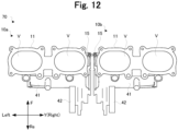
- the throttle device 10 of the present example includes a throttle body 11 having intake passages V
- the intake passages V are configured to send air to the internal combustion engine 5, and the two intake passages V are provided in the throttle body 11.
- the throttle device 10 includes the throttle body 11 equipped with movable members, a sensor, members related to positioning of an adjustment screw or the like.
- the throttle body 11 supports a throttle shaft 21 described later.
- a first throttle valve 12a is provided in an intake passage V and is coupled to the throttle shaft 21.
- a second throttle valve 12b is provided in an intake passage V and is coupled to the throttle shaft 21. That is, as shown in FIG. 3 , butterfly-type throttle valves are provided in the respective intake passages V.
- the first throttle valve 12a and second throttle valve 12b are arranged in the width direction Y.
- the two throttle valves 12a and 12b are fixed to the throttle shaft 21 extending in the width direction Y, and configured to tilt along with rotation of the throttle shaft 21.
- the first throttle valve 12a and second throttle valve 12b rotate integrally with the throttle shaft 21 and tilt to adjust an amount of air passing through the intake passages V.
- the first throttle valve 12a and second throttle valve 12b are in a fully closed position.
- the intake passages V are in a state where it is most difficult for air to pass therethrough.
- the first throttle valve 12a and second throttle valve 12b rotate in an opening direction.
- a tilt angle of the first throttle valve 12a and second throttle valve 12b approaches 90°.
- the first throttle valve 12a and second throttle valve 12b reach a fully open position.
- the intake passages V are in a state where it is easiest for air to pass therethrough.
- the first throttle valve 12a and second throttle valve 12b are an example of the throttle valve of the present invention.
- a drive motor 41 has a drive shaft 22 parallel with the throttle shaft 21.
- the drive shaft 22 is also referred to as a motor shaft.
- the drive motor 41 is configured to rotate the throttle shaft 21.
- the drive shaft 22 is a shaft through which the drive motor 41 outputs rotational force.
- the drive shaft 22 corresponds to a first shaft of the present invention.
- the main body 41b is an example of a motor main body in the present invention.
- the throttle device 10 includes a sensor shaft 23 and a throttle position sensor 42.
- the sensor shaft 23 extends in the width direction Y.
- the sensor shaft 23 is parallel with the throttle shaft 21.
- the sensor shaft 23 is parallel with the drive shaft 22.
- the sensor shaft 23 is parallel with the throttle shaft 21.
- the throttle position sensor 42 is coupled to the sensor shaft 23.
- the throttle position sensor 42 detects a rotation angle of the sensor shaft 23.
- the throttle position sensor 42 is provided at a position close to one end of the drive motor 41.
- the throttle position sensor 42 is provided at a position close to the drive shaft 22.
- the throttle position sensor 42 is provided to the right of the drive motor 41. More specifically, a left end of the throttle position sensor 42 is to the left of a right end of the main body 41b of the drive motor. A right end of the throttle position sensor 42 is to the right of the right end of the main body 41b of the drive motor. This configuration reduces length of the throttle device 10 in the width direction Y.
- the throttle device 10 in this configuration is smaller in dimension in the width direction Y than when in a configuration in which the drive motor 41 and the throttle position sensor 42 are arranged in a row in the width direction Y. Therefore, it is easy to mount the throttle device 10 on the two-wheel motor vehicle 1.
- the throttle position sensor 42 is at the same position as the drive shaft 22 in an extending direction (width direction Y) of the drive shaft 22.
- the throttle position sensor 42 has the left end positioned to the left of a right end of the drive shaft 22 and the right end positioned to the right of a left end of the drive shaft 22.
- At least a portion of the throttle position sensor 42 is at the same position as the drive motor 41. Specifically, the left end of the throttle position sensor 42 is positioned to the left of a right end of the drive motor 41, and the right end of the throttle position sensor 42 is positioned to the right of a left end of the drive motor 41.
- the throttle position sensor 42 is a sensor attached to the throttle device 10, and has a function of detecting rotation of a shaft by using this. That is, a through hole through which a main shaft passes is provided in a housing of the throttle position sensor 42, and the main shaft passes through the through hole and extends rightward (in the width direction Y) from an inside of the throttle position sensor 42.
- the main shaft is a part included in the throttle position sensor 42, and is combined to the sensor shaft 23 extending on an extension of the main shaft when attached to the throttle device 10.
- the main shaft and the sensor shaft 23 are firmly integrated via a spring. Between the main shaft and the sensor shaft 23, there is a clearance necessary for fastening the throttle position sensor 42 to the throttle body 11. Because the clearance is invalidated by biasing force of the spring, there is no backlash between the sensor shaft 23 and the main shaft.
- the rotational force of the drive motor 41 is transmitted to the sensor shaft 23 by a second lever 26. Details of the second lever 26 will be described later.
- the drive shaft 22 is at the same position as the throttle shaft 21 in an extending direction (width direction Y) of the throttle shaft 21.
- the entire drive shaft 22 is positioned to the left of a right end of the throttle shaft 21 and to the right of a left end of the throttle shaft 21. That is, the drive shaft 22 falls within a section extending in the width direction Y, the section being defined by positions of the both ends of the throttle shaft 21.
- the drive shaft 22 is shorter in length than the throttle shaft 21. Therefore, a compact throttle device 10 can be provided.
- the drive shaft 22 is disposed to the left of the sensor shaft 23 in an extending direction (width direction Y) of the sensor shaft 23.
- the present invention is not limited thereto.
- At least a portion of the drive shaft 22 may be disposed at the same position as the sensor shaft 23 in the extending direction (width direction Y) of the sensor shaft 23.
- the left end of the drive shaft 22 may be to the left of a right end of the sensor shaft 23, and the right end of the drive shaft 22 may be to the right of a left end of the sensor shaft 23.
- At least a portion of the drive shaft 22 is at the same position as the first throttle valve 12a in the extending direction (width direction Y) of the throttle shaft 21. Specifically, at least a portion of the drive shaft 22 is positioned to the left of a right end of the first throttle valve 12a and to the right of a left end of the first throttle valve 12a.
- the drive shaft 22 is at the same position as the first throttle valve 12a and second throttle valve 12b in the extending direction of the throttle shaft 21.
- the entire drive shaft 22 is positioned to the left of the right end of the first throttle valve 12a and to the right of the left end of the second throttle valve 12b. That is, the drive shaft 22 falls within a section extending in the width direction Y from the right end of the first throttle valve 12a to the left end of the second throttle valve 12b.
- At least a portion of the throttle position sensor 42 is at the same position as the first throttle valve 12a in the extending direction (width direction Y) of the drive shaft 22. Specifically, at least a portion of the throttle position sensor 42 is positioned to the left of a right end of the first throttle valve 12a and to the right of a left end of the first throttle valve 12a.
- FIG. 6 is a right side view of the throttle device 10. Separation distances of each shaft will be described with reference to FIG. 6 .
- a distance between the sensor shaft 23 and the throttle shaft 21 is equal to or longer than a distance between the drive shaft 22 and the throttle shaft 21.
- the distance between the sensor shaft 23 and the throttle shaft 21 is equal to or longer than a distance between the drive shaft 22 and the sensor shaft 23. That is, the distance between the throttle shaft 21 and the sensor shaft 23 is equal to or longer than other distances, that is, the distance between the throttle shaft 21 and the drive shaft 22 and the distance between the sensor shaft 23 and the drive shaft 22.
- the drive shaft 22 may be disposed at an intermediate position between the throttle shaft 21 and the sensor shaft 23 in a direction connecting the throttle shaft 21 and the sensor shaft 23.
- the throttle device 10 has a compact configuration.
- the transmission mechanism 9 is compact.
- the second lever 26 is compact.
- the transmission mechanism 9 is a mechanical mechanism that transmits rotational force between the throttle shaft 21 and the drive shaft 22.
- the transmission mechanism 9 includes a first arm 20, a rotary member 24, and a first lever 25 (refer to FIG. 2 ).
- the first arm 20 is a member extending in a direction orthogonal to the throttle shaft 21, and is rotatably coupled to the first lever 25.
- the first arm 20 is coupled to the throttle shaft 21.
- the first arm 20 is displaceable between a lying position extending in a horizontal direction and a standing position extending in a vertical direction.
- the throttle shaft 21 rotates along with displacement of the first arm 20.
- the rotary member 24 has a circular shape.
- the rotary member 24 is coupled to the drive shaft 22 and rotates integrally with the drive shaft 22.
- the rotary member 24 is fixed to the drive shaft 22.
- the first lever 25 is a member that transmits rotational force of the rotary member 24 to the first arm 20.
- the first lever 25 extends in a direction orthogonal to the drive shaft 22.
- One end of the first lever 25 is disposed on the rotary member 24, and another end of the first lever 25 is disposed on the first arm 20.
- the first lever 25 is rotatably coupled to the rotary member 24.
- the first lever 25 is configured to rotate the first arm 20 by receiving the rotational force of the rotary member 24.
- the first lever 25 is coupled to the rotary member 24 via a joint 32.
- the joint 32 couples the first lever 25 to the rotary member 24.
- the rotary member 24 has a first protrusion extending in a direction away from the drive shaft 22.
- the one end of the first lever 25 is fastened to the first protrusion of the rotary member 24 via the joint 32.
- the one end of the first lever 25 is rotatable with respect to the first protrusion.
- the first lever 25 is rotatable around the joint 32 with respect to the rotary member 24.
- the rotary shaft of the joint 32 is parallel with the drive shaft 22.
- the joint 32 is provided at a position away from a rotation center of the drive shaft 22.
- the joint 32 is a concavo-convex joint.
- the rotary member 24 has a first projection provided on the first protrusion of the rotary member 24.
- the first lever 25 has a first through hole provided on the one end of the first lever 25.
- the first projection of the rotary member 24 is fitted into the first through hole of the first lever 25.
- the first projection protrudes in a direction (width direction Y) in which the drive shaft 22 extends, and the first through hole penetrates the first lever 25 in the direction (width direction Y) in which the drive shaft 22 extends.
- the joint 32 includes a bearing. The bearing is provided between the first projection of the rotary member 24 and the first through hole of the first lever 25.
- the joint 32 has backlash.
- the joint 32 has a degree of clearance between parts.
- the joint 32 has a degree of clearance between the first projection of the rotary member 24 and the first through hole of the first lever 25. This is because it is necessary to allow a degree of clearance between the parts in order for the joint 32 to operate smoothly.
- the joint 31 is a concavo-convex joint.
- the first arm 20 has a projection provided at the one end of the first arm 20.
- the first lever 25 has a second through hole provided on the another end of the first lever 25.
- the projection of the first arm 20 is fitted into the second through hole of the first lever 25.
- the projection of the first arm 20 protrudes in a direction (width direction Y) in which the throttle shaft 21 extends, and the second through hole penetrates the first lever 25 in the direction (width direction Y) in which the drive shaft 22 extends.
- the joint 31 includes a bearing. The bearing is provided between the projection of the first arm 20 and the second through hole of the first lever 25.
- the joint 31 has backlash.
- the joint 31 has a degree of clearance between parts.
- the joint 31 has a degree of clearance between the projection of the first arm 20 and the second through hole of the first lever 25. This is because it is necessary to allow a degree of clearance between parts in order for the joint 31 to operate smoothly.
- the second lever 26 and a second arm 27 transmit the rotational force of the rotary member 24 to the sensor shaft 23. That is, the second lever 26 and the second arm 27 operate by obtaining the rotational force from the drive motor 41. The rotational force of the rotary member 24 is transmitted to the sensor shaft 23 not via the first arm 20 and the first lever 25. A system of the second lever 26 and the second arm 27 is different from a system of the first arm 20 and the first lever 25.
- the second lever 26 is rotatably coupled to the rotary member 24.
- the second lever 26 is also rotatably coupled to the second arm 27.
- the second arm 27 is a member extending in a direction orthogonal to the sensor shaft 23.
- the second arm 27 is coupled to the sensor shaft 23.
- the second arm 27 is fixed to the sensor shaft 23. Therefore, the second lever 26 is a member that transmits the rotational force of the drive motor 41 to the second arm 27.
- One end of the second lever 26 is disposed on the rotary member 24, and another end of the second lever 26 is disposed on the second arm 27.
- the second lever 26 is configured to rotate the second arm 27 by receiving the rotational force of the rotary member 24.
- the second lever 26 is coupled to the rotary member 24 via a joint 33.
- the joint 33 couples the second lever 26 to the rotary member 24.
- the rotary member 24 has a second protrusion extending in a direction away from the drive shaft 22.
- the one end of the second lever 26 is fastened to the second protrusion of the rotary member 24 via the joint 33.
- the one end of the second lever 26 is rotatable with respect to the second protrusion.
- the second lever 26 is rotatable around the joint 33 with respect to the rotary member 24.
- the rotary shaft of the joint 33 is parallel with the drive shaft 22.
- the second lever 26 is coupled to the second arm 27 via a joint 34.
- the joint 34 couples the second lever 26 to the second arm 27.
- the another end of the second lever 26 is fastened to one end of the second arm 27 via the joint 34.
- the another end of the second lever 26 is rotatable with respect to the one end of the second arm 27.
- the second lever 26 is rotatable around the joint 34 with respect to the second arm 27.
- the rotary shaft of the joint 34 is parallel with the drive shaft 22.
- the transmission mechanism 9 is provided on the right end portion of the throttle body 11.
- the second lever 26 is also provided on the right end portion of the throttle body 11. Therefore, the transmission mechanism 9 and the second lever 26 are positioned on the same end as the entire throttle body 11.
- the first throttle valve 12a is positioned between the transmission mechanism 9 and the second throttle valve 12b along the throttle shaft 21.
- the first throttle valve 12a is disposed on the left of the transmission mechanism 9 and on the right of the second throttle valve 12b.
- the drive shaft 22 is positioned between the transmission mechanism 9 and the second throttle valve 12b in the extending direction (width direction Y) of the throttle shaft 21.
- the drive shaft 22 is positioned to the left of the transmission mechanism 9 and to the right of the second throttle valve 12b.
- the throttle position sensor 42 is positioned between the transmission mechanism 9 and the second throttle valve 12b in the extending direction (width direction Y) of the throttle shaft 21.
- the throttle position sensor 42 is positioned to the left of the transmission mechanism 9 and to the right of the second throttle valve 12b.
- the entire second lever 26 is disposed to the left of the right end of the throttle shaft 21.
- the entire second lever 26 is disposed to the right of the left end of the throttle shaft 21.
- the second lever 26 is provided between the transmission mechanism 9 and the drive motor 41 in the extending direction (width direction Y) of the drive shaft 22.
- the second lever 26 is disposed to the left of the transmission mechanism 9 and to the right of the drive motor 41.
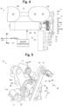
- the second lever 26 is disposed to the left of the first lever 25 and to the right of the drive motor 41. Therefore, the transmission mechanism 9 and the second lever 26 are in different positions in the width direction Y so as not to interfere with each other (refer to FIGS. 2 and 4 ).
- the first lever 25 is positioned to the right of the second lever 26. In other words, with respect to a right end portion of the throttle device 10, the second lever 26 is positioned on a back side of the first lever 25.
- the second lever 26 is provided between the first lever 25 and the drive motor 41 in the extending direction (width direction Y) of the drive shaft 22. Therefore, the right end of the throttle shaft 21 interlocked with the first lever 25 can be disposed on the right end portion of the throttle device 10 as much as possible. It is easy to dispose the second lever 26 to the left of the right end of the throttle body 11 and to the right of a left end of the throttle body 11. For example, it is easy to suppress the second lever 26 from protruding rightward from the throttle body 11. Therefore, it is easy to reduce a dimension of the throttle device 10 in the width direction Y. For example, the dimension of the throttle device 10 in the width direction Y can be reduced as compared with a configuration in which the second lever 26 is positioned to the right of the first lever 25.
- each of the first lever 25 and the second lever 26 is supported by the rotary member 24. That is, rotational force transmission by the first lever 25 and rotational force transmission by the second lever 26 are independent from each other. Therefore, even when the second lever 26 does not function, the first lever 25 functions without being affected by the second lever 26 not functioning, and even when the first lever 25 does not function, the second lever 26 functions without being affected by the first lever 25 not functioning. In this sense, it can be said that the first lever 25 and the second lever 26 are provided in parallel with the rotary member 24. This is because there is no concept of upstream and downstream between the first lever 25 and the second lever 26 from a viewpoint of rotational force transmission. Thus, the first lever 25 and the second lever 26 are not in engagement with each other.
- a return spring 35 is provided on the drive shaft 22 and configured to bias the first throttle valve 12a and second throttle valve 12b in a closing direction via the transmission mechanism 9 described above.
- the return spring 35 positions the first throttle valve 12a and second throttle valve 12b to the fully closed position.
- the drive motor 41 outputs the rotational force
- the first throttle valve 12a and second throttle valve 12b rotate in the opening direction, resisting the biasing force of the return spring 35.
- the return spring 35 is not provided on the throttle shaft 21.
- the return spring 35 is not provided at a position coaxial with the throttle shaft 21.
- the return spring 35 is not provided on the extension of the throttle shaft 21.
- the return spring 35 is at the same position as the throttle shaft 21 in the extending direction (width direction Y) of the throttle shaft 21.
- the entire return spring 35 is disposed to the left of the right end of the throttle shaft 21 and to the right of a left end of the throttle shaft 21. That is, the return spring 35 falls within a section extending in the width direction Y, the section being defined by positions of the both ends of the throttle shaft 21.
- the return spring 35 is disposed in parallel with the throttle shaft 21 in the width direction Y. With this configuration, the return spring 35 does not protrude in the width direction Y with respect to the throttle shaft 21, providing a compact throttle device 10.
- the return spring 35 is at the same position as the first throttle valve 12a and second throttle valve 12b in the extending direction of the throttle shaft 21.
- the entire return spring 35 is positioned to the left of the right end of the first throttle valve 12a and to the right of the left end of the second throttle valve 12b. That is, the return spring 35 falls within a section extending in the width direction Y from the right end of the first throttle valve 12a to the left end of the second throttle valve 12b.
- the return spring 35 is at the same position as the first throttle valve 12a in the extending direction of the throttle shaft 21.
- the entire return spring 35 is positioned to the left of the right end of the first throttle valve 12a and to the right of the left end of the first throttle valve 12a. That is, the return spring 35 falls within a section extending in the width direction Y from the right end of the first throttle valve 12a to the left end of the first throttle valve 12a.
- the return spring 35 is disposed between the main body 41b and the transmission mechanism 9 in the extending direction of the throttle shaft 21.
- the return spring 35 is disposed between the main body 41b and the rotary member 24 in the extending direction of the throttle shaft 21.
- the return spring 35 is disposed at a position sandwiched between the main body 41b and the rotary member 24.
- At least a portion of the return spring 35 may be provided around the rotary member 24.
- the return spring 35 includes an arc-shaped part centered on the drive shaft 22. When deformed, the arc-shaped part of the return spring 35 tries to return to its shape before the deformation. Therefore, the arc-shaped part is a source of the biasing force in the return spring 35.
- the return spring 35 is, for example, a coil spring. An axial direction of the return spring 35 coincides with the extending direction of the drive shaft 22. The drive shaft 22 is inserted into the return spring 35.
- the return spring 35 has a first end 35a and a second end 35b.
- the first end 35a of the return spring 35 is directly or indirectly connected to the drive shaft 22.
- the second end 35b of the return spring 35 is directly or indirectly connected to the throttle body 11.
- FIG. 5 shows a configuration of the return spring 35 of the present example.
- the rotary member 24 includes a locking part 24a.
- the locking part 24a is formed by bending a protrusion extending in a direction away from the drive shaft 22 in a left direction. The direction away from the drive shaft 22 corresponds to a radially outer side of the drive shaft 22.
- the rotary member 24 is fixed to the drive shaft 22. Therefore, the locking part 24a is also fixed to the drive shaft 22.
- the first end 35a is coupled to the locking part 24a. As a result, the first end 35a is directly connected to the rotary member 24.
- the first end 35a is indirectly connected to the drive shaft 22.
- the second end 35b is fixed to the throttle body 11 by a fixing screw 36.
- the second end 35b is directly connected to the throttle body 11.
- a rotation direction F1 illustrated in FIG. 5 denotes a biasing direction of the return spring 35.
- FIG. 5 exemplifies the first end 35a indirectly connected to the drive shaft 22.
- the present invention is not limited thereto.
- the first end 35a may be directly connected to the drive shaft 22.
- FIG. 5 exemplifies the second end 35b directly connected to the throttle body 11.
- the present invention is not limited thereto.
- the second end 35b may be indirectly connected to the throttle body 11.
- FIG. 6 shows rotation directions E1 and E2 around the throttle shaft 21.
- FIG. 6 shows rotation directions F1 and F2 around the drive shaft 22.
- the rotation direction E1 is a counterclockwise direction in a right side view of the two-wheel motor vehicle 1.
- the rotation direction E2 is a clockwise direction in a right side view of the two-wheel motor vehicle 1.
- the rotation direction F1 is an example of a first direction of the present invention.
- the rotation direction F1 is appropriately referred to as a "first direction F1".
- the rotary member 24 rotates integrally with the drive shaft 22 in the rotation direction F2.
- the first lever 25 pushes up the one end of the first arm 20. Therefore, when the rotary member 24 rotates in the rotation direction F2, the first arm 20 rotates in the rotation direction E2.
- the throttle shaft 21 rotates integrally with the first arm 20 in the rotation direction E2.
- the first throttle valve 12a and second throttle valve 12b rotate in the opening direction.
- FIG. 7 is a right side view of the throttle device 10.
- the first arm 20 rotates in the rotation direction E2
- the one end of the first arm 20 is finally pushed up to a position denoted by a broken line in FIG. 7 .
- the throttle shaft 21 When the first arm 20 is at the position denoted by the broken line in FIG. 7 , the throttle shaft 21 is at a maximum angle. When the throttle shaft 21 is at the maximum angle, the first throttle valve 12a and second throttle valve 12b are in the fully open position. For example, when the drive shaft 22 rotates in the rotation direction F2, the first throttle valve 12a and second throttle valve 12b transition from the fully closed position to the fully open position.
- the rotary member 24 rotates integrally with the drive shaft 22 in the first direction F1.
- the first arm 20 rotates in the rotation direction E1.
- the throttle shaft 21 rotates integrally with the first arm 20 in the rotation direction E1.
- the first throttle valve 12a and second throttle valve 12b rotate in the closing direction. For example, the first throttle valve 12a and second throttle valve 12b transition from the fully open position to the fully closed position.
- FIG. 6 shows rotation directions G1 and G2 around the sensor shaft 23.
- the rotary member 24 rotates integrally with the drive shaft 22 in the rotation direction F2.
- the second lever 26 causes the second arm 27 in an upright posture to lie down flat. Therefore, when the rotary member 24 rotates in the rotation direction F2, the second arm 27 rotates in the rotation direction G2.
- the sensor shaft 23 rotates integrally with the second arm 27 in the rotation direction G2.
- the rotary member 24 rotates integrally with the drive shaft 22 in the first direction F1.
- the second arm 27 rotates in the rotation direction G1.
- the sensor shaft 23 rotates integrally with the second arm 27 in the rotation direction G1.
- the rotation angle of the sensor shaft 23 corresponds to a position that the first throttle valve 12a and second throttle valve 12b are in. Therefore, the throttle position sensor 42 detects the position that the first throttle valve 12a and second throttle valve 12b are in.
- the return spring 35 first biases the drive shaft 22 in the first direction F1. Through this, the return spring 35 biases the rotary member 24 in the first direction F1.
- the rotary member 24 rotates in the first direction F1. Therefore, when the drive motor 41 does not output the rotational force, the throttle shaft 21 is at the initial angle, and the first throttle valve 12a and second throttle valve 12b are in the fully closed position.
- the sensor shaft 23 is at the initial angle.
- the drive motor 41 When the rotary member 24 is rotated in the rotation direction F2 by the drive motor 41, the drive motor 41 is required to apply, to the rotary member 24, rotational force that can resist the biasing force of the return spring 35.
- the throttle device 10 in the present example is provided with two stopper mechanisms that limit the rotation operation of the throttle shaft 21, and is provided with one stopper mechanism that limits the rotation operation of the sensor shaft 23. Configurations of these stopper mechanisms will be described.
- a first stopper mechanism S1 is a mechanism that forbids the first throttle valve 12a from further rotating in the closing direction when the first throttle valve 12a is in the fully closed position.
- the first stopper mechanism S1 will be specifically described.
- the first stopper mechanism S1 includes a fully closed position limiter 15 coupled to the throttle body 11 and a first protrusion 20a coupled to the throttle shaft 21.
- the first arm 20 mounted on the throttle shaft 21 has the one end extending from the throttle shaft 21 toward the first lever 25 and the another end extending in a direction away from the first lever 25 with the throttle shaft 21 as a starting point.
- the another end of the first arm 20 has a T shape.
- the first protrusion 20a is disposed on the another end of the first arm 20.
- the first protrusion 20a protrudes in the rotation direction E1.
- the throttle body 11 is provided with the fully closed position limiter 15 that abuts on the first protrusion 20a.
- the fully closed position limiter 15 corresponds to a first limiter of the present invention.
- the first protrusion 20a corresponds to a first rotation contact part of the present invention.
- the first protrusion 20a and the fully closed position limiter 15 constitute the first stopper mechanism S1 of the present invention.
- a second stopper mechanism S2 is a mechanism that forbids the sensor shaft 23 from further rotating in the rotation direction G1 when the first throttle valve 12a is in the fully closed position.
- the second stopper mechanism S2 will be specifically described.
- the second stopper mechanism S2 includes a sensor shaft limiter 17 coupled to the throttle body 11 and a protrusion 27a coupled to the sensor shaft 23.
- the second arm 27 mounted on the sensor shaft 23 has the one end extending from the sensor shaft 23 toward the second lever 26 and the another end extending in a direction away from the second lever 26 with the sensor shaft 23 as a starting point.
- the protrusion 27a is provided on the another end of the second arm 27.
- the protrusion 27a protrudes in the rotation direction G1.
- the throttle body 11 is provided with the sensor shaft limiter 17 that abuts on the protrusion 27a.
- the sensor shaft limiter 17 corresponds to a second limiter of the present invention.
- the protrusion 27a corresponds to a second rotation contact part of the present invention.
- the protrusion 27a and the sensor shaft limiter 17 constitute the second stopper mechanism S2 of the present invention.
- the sensor shaft limiter 17 is a mechanism that forbids the sensor shaft 23 from further rotating in the rotation direction G1 when the first throttle valve 12a and second throttle valve 12b are in the fully closed position.
- the sensor shaft limiter 17 includes an adjustment screw 17b supported by the throttle body 11.
- the protrusion 27a comes into contact with the adjustment screw 17b. A position of the adjustment screw 17b with respect to the throttle body 11 is easily adjusted.
- the sensor shaft limiter 17 includes a lock nut 17a attached via the adjustment screw 17b to a support provided on the throttle body 11.
- the support has a screw hole screwed with the adjustment screw 17b.
- the adjustment screw 17b is rotated in a forward direction, a tip of the adjustment screw 17b emerges from an opening of the screw hole, and when the adjustment screw 17b is rotated in a reverse direction, the tip of the adjustment screw 17b retreats from the opening of the screw hole in the support.
- the adjustment screw 17b can move forward and backward with respect to the throttle body 11.
- the lock nut 17a is a nut screwed with the adjustment screw 17b, and is configured to fix the adjustment screw 17b to the throttle body 11.
- an angle of the sensor shaft 23 corresponding to the first throttle valve 12a and second throttle valve 12b in a fully closed state can be adjusted.
- the fully closed position limiter 15 of the first stopper mechanism S1 has a configuration similar to a configuration of the sensor shaft limiter 17.
- the fully closed position limiter 15 includes an adjustment screw 15b.
- the adjustment screw 15b has a structure similar to a structure of the adjustment screw 17b.
- the fully closed position limiter 15 includes a lock nut 15a.
- the lock nut 15a is configured to fix the adjustment screw 15b to the throttle body 11.
- a contact position between the first protrusion 20a and the adjustment screw 15b is adjusted.
- the initial angle of the throttle shaft 21 is adjusted.
- the first stopper mechanism S 1 including the first protrusion 20a and the fully closed position limiter 15 regulates the throttle shaft 21 so that the throttle shaft 21 does not rotate in the rotation direction E1 anymore.
- the first stopper mechanism S1 sets the initial angle of the throttle shaft 21.
- the adjustment screw 15b adjusts the initial angle of the throttle shaft 21.
- the fully closed position limiter 15 has a configuration that allows fine adjustment of the fully closed position of the first throttle valve 12a and second throttle valve 12b.
- a third stopper mechanism S3 is a mechanism that forbids the first throttle valve 12a from further rotating in the opening direction when the first throttle valve 12a is in the fully open position.
- the third stopper mechanism S3 will be specifically described.
- the third stopper mechanism S3 includes a fully open position limiter 16 coupled to the throttle body 11 and a second protrusion 20b coupled to the throttle shaft 21.
- the second protrusion 20b is provided on the another end of the first arm 20.
- the second protrusion 20b protrudes in the rotation direction E2.
- the fully open position limiter 16 has a similar configuration to the sensor shaft limiter 17.
- the fully open position limiter 16 includes an adjustment screw 16b and a lock nut 16a.
- the adjustment screw 16b has a structure similar to a structure of the adjustment screw 17b.
- the lock nut 16a is configured to fix the adjustment screw 16b to the throttle body 11.
- a contact position between the second protrusion 20b and the adjustment screw 16b is adjusted.
- a maximum value (maximum angle) of the rotation of the throttle shaft 21 is adjusted.
- the third stopper mechanism S3 including the second protrusion 20b and the fully open position limiter 16 regulates the throttle shaft 21 so that the throttle shaft 21 does not rotate in the rotation direction E2 anymore.
- the third stopper mechanism S3 sets the maximum angle of the throttle shaft 21.
- the adjustment screw 16b adjusts the maximum angle of the throttle shaft 21.
- the first throttle valve 12a and second throttle valve 12b are in the fully closed position.
- each of the fully closed position limiter 15, the fully open position limiter 16, and the sensor shaft limiter 17 is appropriately adjusted. That is, in FIG. 6 , the first protrusion 20a of the first arm 20 abuts on the fully closed position limiter 15, and the protrusion 27a of the second arm 27 abuts on the sensor shaft limiter 17.
- the throttle shaft 21 does not rotate in the rotation direction E1.
- the first throttle valve 12a and second throttle valve 12b do not rotate in the closing direction.
- the first throttle valve 12a and second throttle valve 12b are stationary in the fully closed position.
- the sensor shaft 23 does not rotate in the rotation direction G1.
- a movable part between the first lever 25 and the rotary member 24 has backlash.
- the backlash slightly allows the drive shaft 22 to rotate in a state where the throttle shaft 21 is stationary. Therefore, the drive shaft 22 may slightly rotate in the first direction F1 in a state where the first throttle valve 12a and second throttle valve 12b are stationary in the fully closed position. This means that the drive shaft 22 may rotate by the backlash in a state where the first throttle valve 12a and second throttle valve 12b are stationary in the fully closed position.
- the sensor shaft 23 may rotate slightly according to the slight rotation of the drive shaft 22 allowed by the backlash described above. This means that, if the throttle device 10 does not include the second stopper mechanism S2, the sensor shaft 23 may rotate in the rotation direction G1 in a state where the first throttle valve 12a and second throttle valve 12b are stationary in the fully closed position.
- the protrusion 27a may move to the rearward Re and continue to be on the sensor shaft limiter 17. This means that when the adjustment screw 17b is moved slightly rearward Re, the sensor shaft 23 may rotate slightly in the rotation direction G1.
- the sensor shaft 23 may rotate after the first stopper mechanism S 1 forbids the rotation of the throttle shaft 21. Therefore, the sensor shaft 23 may rotate in the rotation direction G1 or the rotation direction G2 in a state where the first throttle valve 12a and second throttle valve 12b are stationary in the fully closed position. This means that the rotation angle of the sensor shaft 23 changes in a state where the first throttle valve 12a and second throttle valve 12b are stationary in the fully closed position.
- an event in which the sensor shaft 23 rotates slightly in the rotation direction G1 is referred to as excessive rotation of the sensor shaft 23.
- the excessive rotation of the sensor shaft 23 adversely affects detection accuracy of the opening degree of the first throttle valve 12a and second throttle valve 12b.
- the rotation angle of the sensor shaft 23 changes in a state where the first throttle valve 12a and second throttle valve 12b are stationary in the fully closed position the position the first throttle valve 12a and second throttle valve 12b are in is not accurately reflected in the rotation angle of the sensor shaft 23.
- the position the first throttle valve 12a and second throttle valve 12b are in is not accurately reflected in the rotation angle of the sensor shaft 23, it is difficult for the throttle position sensor 42 to accurately detect the position that the first throttle valve 12a and second throttle valve 12b are in.
- each of the fully closed position limiter 15 and the sensor shaft limiter 17 is appropriately adjusted. Therefore, as the first arm 20 starts to rotate, the second arm 27 starts to rotate. That is, in FIG. 6 , the excessive rotation of the sensor shaft 23 does not actually occur.
- FIG. 7 shows a case where the fully closed position limiter 15 and the sensor shaft limiter 17 are appropriately adjusted.
- a gap D1 is generated between the fully closed position limiter 15 and the first protrusion 20a.
- a gap D2 is generated between the sensor shaft limiter 17 and the protrusion 27a.
- the sensor shaft 23 rotates at the same time as the throttle shaft 21 rotates.
- a timing at which the throttle shaft 21 starts to rotate in the rotation direction E2 from the initial angle coincides with a timing at which the sensor shaft 23 starts to rotate in the rotation direction G2 from the initial angle. Therefore, the gap D1 and the gap D2 are simultaneously generated. Therefore, the throttle position sensor 42 can accurately detect the position that the first throttle valve 12a and second throttle valve 12b are in.
- the throttle position sensor 42 can accurately detect the position that the first throttle valve 12a and second throttle valve 12b are in.
- FIG. 8 shows the throttle device 10 when the adjustment of the sensor shaft limiter 17 is intentionally shifted from the state in FIG. 6 for description.
- the protrusion 27a follows the adjustment screw 17b. That is, the second arm 27 and the sensor shaft 23 slightly rotate in the rotation direction G1, and the drive shaft 22 slightly rotates in the first direction F1.
- the rotation of the sensor shaft 23 in the rotation direction G1 is derived from the biasing force of the return spring 35.
- the rotation of the drive shaft 22 in the first direction F1 is also derived from the biasing force of the return spring 35.
- the throttle shaft 21 does not rotate regardless of the rotation of the sensor shaft 23. This is because the rotation of the throttle shaft 21 in the rotation direction E1 is forbidden by the first protrusion 20a of the first arm 20 abutting on the fully closed position limiter 15. Because there is a clearance in each link mechanism, the sensor shaft 23 rotates in the rotation direction G1 even though the throttle shaft 21 is stopped. The clearance impairs synchronization between the rotation of the throttle shaft 21 and the rotation of the sensor shaft 23.
- the second stopper mechanism S2 does not stop the rotation of the sensor shaft 23 at an appropriate timing, the rotation angle of the sensor shaft 23 may change in a state where the throttle shaft 21 is not rotating.
- the throttle position sensor 42 detects the rotation of the sensor shaft 23 to estimate the position that the first throttle valve 12a and second throttle valve 12b are in. Therefore, if the rotation of the throttle shaft 21 and the rotation of the sensor shaft 23 are not synchronized with each other, detection accuracy of the throttle position sensor 42 decreases. For example, the throttle position sensor 42 erroneously detects that the throttle shaft 21 is rotating although the throttle shaft 21 is not actually rotating. For example, when the first throttle valve 12a is not actually rotating, the throttle position sensor 42 acquires an erroneous detection result indicating that the first throttle valve 12a is rotating.
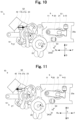
- FIGS. 9 to 11 illustrate a method for adjusting the sensor shaft limiter 17.
- FIG. 9 shows a state where the adjustment screw 17b as the sensor shaft limiter 17 is moved slightly forward F from the state in FIG. 8 .
- the adjustment screw 17b moves, the second arm 27 and the sensor shaft 23 rotate in the rotation direction G2.
- the throttle shaft 21 remains stopped. Because there is a clearance in each link mechanism, the throttle shaft 21 remains stopped even though the sensor shaft 23 rotates in the rotation direction G2.
- FIG. 10 shows a state where the adjustment screw 17b as the sensor shaft limiter 17 is moved further forward F from the state in FIG. 9 .
- the sensor shaft 23 rotates further in the rotation direction G2.
- the rotation angle of the sensor shaft 23 exceeds an angle that can be allowed by the clearance of each link mechanism. Thereafter, the first arm 20 and the throttle shaft 21 start to rotate in the rotation direction E2.
- FIG. 11 shows a state where the adjustment screw 17b as the sensor shaft limiter 17 is moved rearward Re from the state in FIG. 10 .
- the protrusion 27a follows the adjustment screw 17b and continues to be on the adjustment screw 17b.
- the sensor shaft 23 rotates in the rotation direction G1.
- the drive shaft 22 rotates in the first direction F1.
- the throttle shaft 21 rotates in the rotation direction E1.
- FIG. 11 shows a moment when the first protrusion 20a of the first arm 20 abuts on the fully closed position limiter 15.
- the position of the adjustment screw 17b at the moment when the first protrusion 20a abuts on the fully closed position limiter 15 is optimal. Therefore, the adjustment screw 17b is fixed to the position of the adjustment screw 17b at the moment when the first protrusion 20a abuts on the fully closed position limiter 15. That is, the sensor shaft limiter 17 is appropriately adjusted.
- the second stopper mechanism S2 appropriately adjusts the initial angle of the sensor shaft 23.
- the rotation angle of the sensor shaft 23 is adjusted so that the sensor shaft 23 starts to rotate at the same time as the throttle shaft 21 starts to rotate.
- the position of the adjustment screw 17b in FIG. 11 is substantially the same as the position of the adjustment screw 17b in FIG. 6 .
- the angle of the sensor shaft 23 may be within a certain range (from - ⁇ to + ⁇ ).
- the angle of the sensor shaft 23 in FIG. 11 is defined to be at an end (+ ⁇ ) in the rotation direction G2 within the certain range.
- the angle + ⁇ is an angle does not allow the clearance of the link mechanism to act on the rotation of the throttle shaft 21. Therefore, when the sensor shaft limiter 17 is adjusted as illustrated in FIG. 11 , each link mechanism operates as if there is no clearance. As a result, the rotation angle of the sensor shaft 23 is proportional to the rotation angle of the throttle shaft 21.
- the throttle position sensor 42 accurately detects the rotation of the throttle shaft 21.
- the throttle position sensor 42 accurately detects the position that the first throttle valve 12a and second throttle valve 12b are in.
- the adjustment screw 17b is moved forward F in a state where the first protrusion 20a is in contact with the fully closed position limiter 15.
- the sensor shaft 23 is rotated in the rotation direction G2
- the drive shaft 22 is rotated in the rotation direction F2
- the throttle shaft 21 is rotated in the rotation direction E2
- the first protrusion 20a is separated from the fully closed position limiter 15.
- the adjustment screw 17b is moved rearward Re.
- the sensor shaft 23 is rotated in the rotation direction G1
- the drive shaft 22 is rotated in the first direction F1
- the throttle shaft 21 is rotated in the rotation direction E1.
- the movement of the adjustment screw 17b is stopped when the first protrusion 20a abuts on the fully closed position limiter 15.
- the adjustment screw 17b is fixed to the position.
- the motor controller 61 transmits, to the drive motor 41, a control signal of which a duty ratio is to be indicated.
- the drive motor 41 generates the rotational force in accordance with the control signal.
- the duty ratio is lower than a predetermined value
- the rotational force of the drive motor 41 cannot resist the biasing force of the return spring 35.
- the angle of the throttle shaft 21 does not change from the initial angle.
- the drive motor 41 rotates the throttle shaft 21 in the rotation direction E2, resisting the biasing force of the return spring 35.
- the throttle shaft 21 stops rotating when the rotational force of the drive motor 41 and rotational force of the return spring 35 are balanced (refer to FIG. 7 ).
- the motor controller 61 is configured to change the opening degree of the first throttle valve 12a and second throttle valve 12b by controlling the duty ratio of the control signal.
- a time point of accelerator operation by the driver and a time point of starting rotation of the first throttle valve 12a and second throttle valve 12b it is possible to cause a time point of accelerator operation by the driver and a time point of starting rotation of the first throttle valve 12a and second throttle valve 12b to be more coincident with each other. In order to do so, it is only required, before the accelerator operation, to continue to supply the drive motor 41 with a control signal having a duty ratio that is low enough that the throttle shaft 21 does not rotate. Then, the first throttle valve 12a and second throttle valve 12b are opened when the duty ratio is increased by the accelerator operation by the driver.
- output from the throttle position sensor 42 is input to the motor controller 61 and used for feedback control of the motor controller 61.
- the throttle device 10 includes the throttle body 11, the throttle shaft 21, and the throttle valves (12a and 12b).
- the throttle body 11 has the intake passages V.
- the throttle shaft 21 is supported by the throttle body 11.
- the throttle valves (12a and 12b) are provided in the intake passages V.
- the throttle valves (12a and 12b) are coupled to the throttle shaft 21. Therefore, the first throttle valves (12a and 12b) rotate integrally with the throttle shaft 21.
- the throttle valves (12a and 12b) open and close the intake passages V
- the throttle device 10 includes the drive shaft 22, the transmission mechanism 9, and the return spring 35.
- the drive shaft 22 is parallel with the throttle shaft 21.
- the transmission mechanism 9 transmits rotational force between the throttle shaft 21 and the drive shaft 22.
- the return spring 35 is provided on the drive shaft 22.
- the return spring 35 biases the throttle valves (12a and 12b) in the closing direction via the transmission mechanism 9. Therefore, the return spring 35 is not provided on the throttle shaft 21.
- the return spring 35 is not provided on the extension of the throttle shaft 21. Therefore, the throttle shaft 21 can be shortened. Therefore, the throttle device 10 is more compact than a conventional device.
- the drive shaft 22 and the throttle shaft 21 overlap each other in the extending direction of the throttle shaft 21. Therefore, the drive shaft 22 does not contribute to an increase in the length of the throttle device 10 in the extending direction of the throttle shaft 21. Therefore, it is possible to prevent an increase in size of the throttle device 10 due to the provision of the drive shaft 22. Therefore, the throttle device 10 is even smaller in size.
- the drive motor 41 includes the main body 41b.
- the return spring 35 is disposed between the main body 41b and the transmission mechanism 9 in the extending direction of the drive shaft 21. Therefore, it is easy to provide the return spring 35 on the drive shaft 22. For example, it is easy to provide the return spring 35 on the drive shaft 22 by a slight design change. More specifically, by lengthening the drive shaft 22 by a width of the return spring 35, it is easy to provide the return spring 35 on the drive shaft 22.
- the return spring 35 includes an arc-shaped configuration that generates biasing force.
- the arc-shaped part is centered on the drive shaft 22. Therefore, it is easy for the return spring 35 to apply biasing force to the drive shaft 22.
- the first end 35a of the return spring 35 is connected to the drive shaft 22, and the second end 35b of the return spring 35 is connected to the throttle body 11.
- the return spring 35 can be configured to rotate the drive shaft 22 in a predetermined direction with respect to the throttle body 11.
- the predetermined direction is a first rotation direction G1. That is, the return spring 35 that biases the first throttle valve 12a and second throttle valve 12b in the closing direction can be easily configured.
- the first end 35a of the return spring 35 is connected to the drive shaft 22 through the locking part 24a fixed to the drive shaft 22. With this configuration, a locked state of the return spring 35 can be configured only by winding an end of the return spring 35 around the locking part 24a.
- the throttle device 10 includes the first unit 10a and the second unit 10b that are mirror-symmetric to each other In Modification 1 described above.
- the present invention is not limited to this configuration.
- the throttle device 70 may include two first units 10a.
- the throttle device 70 may include two second units 10b.
- the two first units 10a or the two second units 10b are arranged in the width direction Y. With such a configuration, the drive motor 41 is exposed in the width direction Y. Therefore, an effect of the present invention that can downsize the throttle device 10 is applied is greater.
- the return spring 35 is provided on the drive shaft 22.
- the present invention is not limited to this configuration.
- the return spring 35 may be provided on the sensor shaft 23.
- the throttle position sensor 42 of the present modification is configured to detect the rotation angle of the sensor shaft 23 provided with the return spring 35.
- the return spring 35 is provided on a sensor shaft 23 for detecting the opening degree of the throttle valves (12a and 12b). Therefore, with this configuration, it is not necessary to provide a new shaft for the return spring 35. Therefore, it is possible to provide the throttle device 10 with a simplified device configuration.
- the first arm 20, the rotary member 24, the first lever 25, the second lever 26, and the second arm 27 transmit rotational force between the throttle shaft 21 and the drive shaft 22.
- the return spring 35 is disposed between the throttle position sensor 42 and the transmission mechanisms (20, 24, 25, 26, and 27) in the extending direction of the sensor shaft 23. Therefore, it is easy to provide the return spring 35 on the sensor shaft 23. For example, it is easy to provide the return spring 35 on the sensor shaft 23 by a slight design change. More specifically, by lengthening the sensor shaft 23 by a width of the return spring 35, it is easy to provide the return spring 35 on the sensor shaft 23.
- the first end 35a of the return spring 35 is directly or indirectly connected to the sensor shaft 23.
- the second end 35b of the return spring 35 is directly or indirectly connected to the throttle body 11.
- the first end 35a of the return spring 35 is coupled to a locking part 27b provided on the second arm 27.
- the second arm 27 is fixed to the sensor shaft 23. Therefore, the locking part 27b is also fixed to the sensor shaft 23.
- the first end 35a is coupled to the locking part 27b. As a result, the first end 35a is directly connected to the second arm 27.
- the first end 35a is indirectly connected to the sensor shaft 23.
- the second end 35b is fixed to the throttle body 11 by a fixing screw 36.
- the second end 35b is directly connected to the throttle body 11.
- the sensor shaft 23 of the present modification is an example of the first shaft of the present invention.
- the rotary member 24, the first lever 25, the first arm 20, the second lever 26, and the second arm 27 of the present modification are an example of a transmission mechanism of the present invention.
- the rotation direction G1 of the present modification is an example of the first direction G1 of the present invention.
- the return spring 35 is not necessarily provided on the drive shaft 22 or the sensor shaft 23.
- the return spring 35 may be provided on a shaft other than the throttle shaft 21, the drive shaft 22, and the sensor shaft 23.
- the throttle device 10 includes a return spring shaft 18.
- the return spring shaft 18 is different from any of the throttle shaft 21, the drive shaft 22, and the sensor shaft 23.
- the return spring shaft 18 extends in the width direction Y.
- the return spring shaft 18 is parallel with the throttle shaft 21.
- the return spring 35 is provided on the return spring shaft 18.
- the return spring shaft 18 of the present modification is an example of the first shaft of the present invention. According to the present modification, it is easy to increase flexibility of arrangement of the return spring shaft 18. Therefore, it is easy to increase flexibility of arrangement of the return spring 35.
- An original moving gear 19 is fixed to the return spring shaft 18.
- the original moving gear 19 may be formed integrally with the return spring shaft 18.
- a rotation center of the original moving gear 19 coincides with the return spring shaft 18.
- a driven gear 24b is fixed to the rotary member 24.
- the driven gear 24b may be formed integrally with the rotary member 24.
- a rotation center of the driven gear 24b coincides with the drive shaft 22.
- the driven gear 24b meshes with the original moving gear 19.
- the original moving gear 19, the rotary member 24, the driven gear 24b, the first lever 25, and the first arm 20 transmit rotational force between the throttle shaft 21 and the return spring shaft 18.
- the original moving gear 19, the rotary member 24, the driven gear 24b, the first lever 25, and the first arm 20 of the present modification are an example of a transmission mechanism of the present invention.
- the return spring 35 biases the original moving gear 19 in a predetermined direction.
- the driven gear 24b rotates in the rotation direction F1. Therefore, the return spring 35 biases the rotary member 24 in the rotation direction F1 via the original moving gear 19 and the driven gear 24b. Therefore, the return spring 35 biases the first throttle valve 12a and second throttle valve 12b in the closing direction via the original moving gear 19, the rotary member 24, the first lever 25, and the first arm 20.
- the first end 35a of the return spring 35 is directly or indirectly connected to the return spring shaft 18.
- the second end 35b of the return spring 35 is directly or indirectly connected to the throttle body 11.
- the first end 35a of the return spring 35 is inserted into a through hole provided on the original moving gear 19.
- the original moving gear 19 is fixed to the return spring shaft 18. Therefore, the through hole of the original moving gear 19 is also fixed to the return spring shaft 18.
- the first end 35a is coupled to the through hole of the original moving gear 19. As a result, the first end 35a is fixed to the return spring shaft 18 via the original moving gear 19.
- the through hole of the original moving gear 19 is an example of a locking part of the present invention.
- the second end 35b of the return spring 35 is fixed to the throttle body 11 by the fixing screw 36.
- the second end 35b is directly connected to the throttle body 11.
- the throttle device 10 according to the above-described embodiment is mounted on the two-wheel motor vehicle 1.
- the present invention is not limited to this configuration.
- the present invention can also be applied to other straddled vehicles.
- the number of the front wheel 3 is not limited thereto.
- the number of the rear wheel 4 is also not limited thereto.
Landscapes
- Engineering & Computer Science (AREA)
- Chemical & Material Sciences (AREA)
- Combustion & Propulsion (AREA)
- Mechanical Engineering (AREA)
- General Engineering & Computer Science (AREA)
- Control Of Throttle Valves Provided In The Intake System Or In The Exhaust System (AREA)
Abstract
Description
- The present invention relates to a throttle device. The present invention relates to a straddled vehicle including the throttle device.
- A throttle device described in
Patent Document 1 includes a throttle body, a throttle shaft, a throttle valve, and a return spring. The throttle body has an intake passage. The throttle shaft is supported by the throttle body. The throttle valve is provided in the intake passage. The throttle valve is coupled to the throttle shaft. The return spring biases the throttle valve in a closing direction. The return spring is provided on the throttle shaft. The return spring is disposed concentrically with the throttle shaft. -
JP 2013-104389 A - A conventional throttle device is relatively large. Specifically, the throttle device is long in an extending direction of the throttle shaft. Therefore, it is difficult to mount the throttle device on a straddled vehicle.
- The present invention has been made in view of such circumstances, and an object of the present invention is to provide a small throttle device and a straddled vehicle including the throttle device.
- In order to solve the above problem, the present invention has the following configurations.
- That is, the present invention is a throttle device including a throttle body having an intake passage, a throttle shaft supported by the throttle body, a throttle valve provided in the intake passage and coupled to the throttle shaft, a first shaft parallel with the throttle shaft, a transmission mechanism configured to transmit rotational force between the throttle shaft and the first shaft, and a return spring provided on the first shaft and configured to bias the throttle valve in a closing direction via the transmission mechanism.
- The above-described throttle device includes the throttle body, the throttle shaft, and the throttle valve. The throttle body has an intake passage. The throttle shaft is supported by the throttle body. The throttle valve is provided in the intake passage. The throttle valve is coupled to the throttle shaft. Therefore, the throttle valve rotates integrally with the throttle shaft. When the throttle shaft rotates, the throttle valves open and close the intake passages.
- The throttle device includes the first shaft, the transmission mechanism, and the return spring. The first shaft is parallel with the throttle shaft. The transmission mechanism transmits rotational force between the throttle shaft and the first shaft. The return spring is provided on the first shaft. The return spring biases the throttle valve in the closing direction via the transmission mechanism. Therefore, the return spring is not provided on the throttle shaft. The return spring is not provided on an extension of the throttle shaft. Therefore, the throttle shaft can be shortened. Therefore, the throttle device is more compact than a conventional device.
- In the throttle device described above, the return spring is preferably at the same position as the throttle shaft in an extending direction of the throttle shaft.
- In the above-described configuration, the return spring and the throttle shaft overlap each other in the extending direction of the throttle shaft. Therefore, the return spring does not contribute to an increase in length of the throttle device in the extending direction of the throttle shaft. Therefore, it is possible to prevent an increase in size of the throttle device due to the provision of the return spring. Therefore, the throttle device is even smaller in size.
- In the throttle device described above, the return spring is preferably at the same position as the throttle valve in the extending direction of the throttle shaft.
- In the above-described configuration, the return spring and the throttle valve overlap each other in the extending direction of the throttle shaft. Therefore, it is easy to dispose the return spring at the same position as the throttle shaft in the extending direction of the throttle shaft. In this way, a compact throttle device can be easily implemented.
- In the throttle device described above, the first shaft is preferably at the same position as the throttle shaft in the extending direction of the throttle shaft.
- According to the above-described configuration, the first shaft and the throttle shaft overlap each other in the extending direction of the throttle shaft. Therefore, the first shaft does not contribute to an increase in the length of the throttle device in the extending direction of the throttle shaft. Therefore, it is possible to prevent an increase in size of the throttle device due to the provision of the first shaft. Therefore, the throttle device is even smaller in size.
- In the throttle device described above, the first shaft is preferably at the same position as the throttle valve in the extending direction of the throttle shaft.
- According to the above-described configuration, the first shaft and the throttle valve overlap each other in the extending direction of the throttle shaft. Therefore, it is easy to dispose the first shaft at the same position as the throttle shaft in the extending direction of the throttle shaft. In this way, a compact throttle device can be easily implemented.
- The throttle device described above preferably further includes a drive motor configured to drive the throttle valve, in which the first shaft is preferably a drive shaft included in the drive motor.
- According to the above-described configuration, the return spring is provided on the drive shaft for driving the throttle valve. With this configuration, it is not necessary to provide a new shaft for the return spring. Therefore, it is possible to provide the throttle device with a simplified device configuration.
- In the throttle device described above, the drive motor preferably includes a motor main body configured to output rotational force to the drive shaft, and the return spring is preferably disposed between the motor main body and the transmission mechanism in an extending direction of the drive shaft.
- According to the above-described configuration, it is easy to provide the return spring on the drive shaft.
- The throttle device described above preferably further includes a throttle position sensor configured to detect a rotation angle of the first shaft.
- According to the above-described configuration, the rotation angle of the first shaft corresponds to a position that the throttle valve is in. The throttle position sensor is configured to directly detect the rotation angle of the first shaft, thereby indirectly detecting the position the throttle valve is in. The first shaft is a so-called "sensor shaft". The return spring is provided on the sensor shaft for detecting an opening degree of the throttle valve. With this configuration, it is not necessary to provide a new shaft for the return spring. Therefore, it is possible to provide the throttle device with a simplified device configuration.
- In the throttle device described above, the return spring is preferably disposed between the throttle position sensor and the transmission mechanism in an extending direction of the first shaft.
- According to the above-described configuration, it is easy to provide the return spring on the drive shaft.
- The throttle device described above preferably further includes a sensor shaft parallel with the throttle shaft and different from the first shaft, a drive motor parallel with the throttle shaft and having a drive shaft different from the first shaft, and a throttle position sensor configured to detect a rotation angle of the sensor shaft.
- According to the above-described configuration, the throttle device includes the first shaft, the throttle shaft, the drive shaft, and the sensor shaft. Here, the first shaft is different from any of the throttle shaft, the drive shaft, and the sensor shaft. The return spring is provided on the first shaft different from the throttle shaft, the drive shaft, and the sensor shaft. Therefore, it is easy to increase flexibility of arrangement of the first shaft and the return spring.
- In the throttle device described above, the return spring preferably includes an arc-shaped part centered on the first shaft.
- According to the above-described configuration, the return spring includes an arc-shaped configuration that generates biasing force. The arc-shaped part is centered on the first shaft. Therefore, it is easy for the return spring to apply biasing force to the first shaft.
- In the throttle device described above, the return spring preferably includes a first end connected to the first shaft directly or indirectly, and a second end connected to the throttle body directly or indirectly.
- According to the above-described configuration, the first end of the return spring is connected to the first shaft, and the second end of the return spring is connected to the throttle body. With this configuration, the return spring can be configured to rotate the first shaft in a predetermined direction with respect to the throttle body. That is, the return spring that biases the throttle valve in the closing direction can be easily configured.
- The throttle device described above preferably further includes a locking part fixed to the first shaft, in which the first end of the return spring is preferably coupled to the locking part.
- According to the above-described configuration, the first end of the return spring is connected to the first shaft through the locking part fixed to the first shaft. With this configuration, a locked state of the return spring can be configured only by winding an end of the return spring around the locking part.
- In the throttle device described above, the first shaft is preferably configured to rotate in a first direction when the throttle valve rotates in the closing direction, and the return spring is preferably configured to bias the first shaft to the first direction.
- According to the above-described configuration, it is easy for the return spring to bias the throttle valve in the closing direction.
- A straddled vehicle of the present invention includes the throttle device. It is easy to mount the throttle device on the straddled vehicle, because the throttle device is smaller than a conventional throttle device.
- The throttle device of the present invention is compact.
-
-
FIG. 1 is a plan view for describing an overall configuration of a two-wheel motor vehicle according to an embodiment. -
FIG. 2 is a perspective view for describing a throttle device according to the embodiment. -
FIG. 3 is a plan view for describing a throttle body according to the embodiment. -
FIG. 4 is aplan view for describing a positional relationship among respective shafts according to the embodiment. -
FIG. 5 is a perspective view for describing a return spring according to the embodiment. -
FIG. 6 is a right side view for describing operation of the throttle device according to the embodiment. -
FIG. 7 is a right side view for describing operation of the throttle device according to the embodiment. -
FIG. 8 is a right side view for describing operation of the throttle device according to the embodiment. -
FIG. 9 is a right side view for describing operation of the throttle device according to the embodiment. -
FIG. 10 is a right side view for describing operation of the throttle device according to the embodiment. -
FIG. 11 is a right side view for describing operation of the throttle device according to the embodiment. -
FIG. 12 is a plan view for describing one modification of the present invention. -
FIG. 13 is a plan view for describing one modification of the present invention. -
FIG. 14 is a perspective view for describing one modification of the present invention. - A detailed description will hereinafter be given of an embodiment of the present invention with consultation of drawings. A vehicle of the embodiment is a straddled vehicle including an internal combustion engine. The vehicle according to the embodiment includes a throttle device. The throttle device adjusts an amount of intake air supplied to the internal combustion engine. The throttle device includes butterfly-type throttle valves, a mechanism for rotating the throttle valves, and a mechanism for detecting an opening degree of the throttle valves.
-
FIG. 1 shows an overall configuration of a two-wheel motor vehicle 1 of the present invention. The two-wheel motor vehicle 1 is an example of a straddled vehicle. As shown inFIG. 1 , the two-wheel motor vehicle 1 according to the embodiment includes avehicle body frame 51, afront wheel 3 andrear wheel 4, an internal combustion engine (engine) 5 having a two-cylinder configuration, an exterior cover, and aseat 53. The two-wheel motor vehicle 1 according to the embodiment includes afront fork 6 that supports thefront wheel 3 and ahandlebar 54 for rotating thefront fork 6. To ride on the two-wheel motor vehicle 1, a driver sits on theseat 53 while gripping thehandlebar 54 and straddles the two-wheel motor vehicle 1. When the driver operates an accelerator in this state, the throttle device is operated accordingly, and the amount of intake air supplied to theinternal combustion engine 5 is adjusted. - Note that the reference sign F in
FIG. 1 denotes forward of the vehicle, and the reference sign Re denotes rearward of the vehicle. InFIG. 1 , the reference sign U denotes an upward direction, and reference sign D denotes a downward direction. A width direction Y is a direction orthogonal to a front-rear direction and an up-down direction. The front-rear direction, the up-down direction, and the width direction Y are defined with reference to the driver riding on the two-wheel motor vehicle 1. In the following drawings as well, these reference signs are appropriately denoted in order to clarify a direction of each member installed in the two-wheel motor vehicle 1. -
FIG. 2 is a perspective view showing a configuration of athrottle device 10 according to the embodiment. Thethrottle device 10 is directly or indirectly connected to theinternal combustion engine 5. As shown inFIG. 2 , thethrottle device 10 of the present example includes athrottle body 11 having intake passages V The intake passages V are configured to send air to theinternal combustion engine 5, and the two intake passages V are provided in thethrottle body 11. Thethrottle device 10 includes thethrottle body 11 equipped with movable members, a sensor, members related to positioning of an adjustment screw or the like. Thethrottle body 11 supports athrottle shaft 21 described later. - Refer to
FIG. 3 . Afirst throttle valve 12a is provided in an intake passage V and is coupled to thethrottle shaft 21. Similarly, asecond throttle valve 12b is provided in an intake passage V and is coupled to thethrottle shaft 21. That is, as shown inFIG. 3 , butterfly-type throttle valves are provided in the respective intake passages V. Thefirst throttle valve 12a andsecond throttle valve 12b are arranged in the width direction Y. The twothrottle valves throttle shaft 21 extending in the width direction Y, and configured to tilt along with rotation of thethrottle shaft 21. Thefirst throttle valve 12a andsecond throttle valve 12b rotate integrally with thethrottle shaft 21 and tilt to adjust an amount of air passing through the intake passages V. - When the
throttle shaft 21 is at an initial angle, thefirst throttle valve 12a andsecond throttle valve 12b are in a fully closed position. When thefirst throttle valve 12a andsecond throttle valve 12b are in the fully closed position, the intake passages V are in a state where it is most difficult for air to pass therethrough. When thethrottle shaft 21 is rotated from the initial angle, thefirst throttle valve 12a andsecond throttle valve 12b rotate in an opening direction. When thefirst throttle valve 12a andsecond throttle valve 12b rotate in the opening direction, a tilt angle of thefirst throttle valve 12a andsecond throttle valve 12b approaches 90°. Eventually, thefirst throttle valve 12a andsecond throttle valve 12b reach a fully open position. When thefirst throttle valve 12a andsecond throttle valve 12b are in the fully open position, the intake passages V are in a state where it is easiest for air to pass therethrough. - The
first throttle valve 12a andsecond throttle valve 12b are an example of the throttle valve of the present invention. - As shown in
FIG. 4 , adrive motor 41 has adrive shaft 22 parallel with thethrottle shaft 21. Thedrive shaft 22 is also referred to as a motor shaft. Thedrive motor 41 is configured to rotate thethrottle shaft 21. Thedrive shaft 22 is a shaft through which thedrive motor 41 outputs rotational force. Thedrive shaft 22 corresponds to a first shaft of the present invention. - The
drive motor 41 is configured to drive thefirst throttle valve 12a andsecond throttle valve 12b through rotation drive of thethrottle shaft 21. As shown inFIG. 4 , thedrive motor 41 has amain body 41b that outputs rotational force to thedrive shaft 22. Themain body 41b has a cylindrical shape extending in the width direction Y. Thedrive shaft 22 protrudes in the width direction Y from themain body 41b. For example, thedrive shaft 22 extends rightward from themain body 41b. In themain body 41b, electromagnetic coils and permanent magnets are concentrically arranged. The rotational force of thedrive motor 41 is transmitted to thethrottle shaft 21 by atransmission mechanism 9. Details of thetransmission mechanism 9 will be described later. - The
main body 41b is an example of a motor main body in the present invention. - The
throttle device 10 includes asensor shaft 23 and athrottle position sensor 42. Thesensor shaft 23 extends in the width direction Y. Thesensor shaft 23 is parallel with thethrottle shaft 21. Thesensor shaft 23 is parallel with thedrive shaft 22. Thesensor shaft 23 is parallel with thethrottle shaft 21. Thethrottle position sensor 42 is coupled to thesensor shaft 23. Thethrottle position sensor 42 detects a rotation angle of thesensor shaft 23. - As shown in
FIG. 4 , thethrottle position sensor 42 is provided at a position close to one end of thedrive motor 41. Thethrottle position sensor 42 is provided at a position close to thedrive shaft 22. For example, thethrottle position sensor 42 is provided to the right of thedrive motor 41. More specifically, a left end of thethrottle position sensor 42 is to the left of a right end of themain body 41b of the drive motor. A right end of thethrottle position sensor 42 is to the right of the right end of themain body 41b of the drive motor. This configuration reduces length of thethrottle device 10 in the width direction Y. For example, thethrottle device 10 in this configuration is smaller in dimension in the width direction Y than when in a configuration in which thedrive motor 41 and thethrottle position sensor 42 are arranged in a row in the width direction Y. Therefore, it is easy to mount thethrottle device 10 on the two-wheel motor vehicle 1. - The
drive motor 41 is provided on a right end portion of thethrottle body 11. Thethrottle position sensor 42 is also provided on the right end portion of thethrottle body 11. - As can be seen with reference to
FIG. 4 , at least a portion of thethrottle position sensor 42 is at the same position as thedrive shaft 22 in an extending direction (width direction Y) of thedrive shaft 22. Specifically, thethrottle position sensor 42 has the left end positioned to the left of a right end of thedrive shaft 22 and the right end positioned to the right of a left end of thedrive shaft 22. - At least a portion of the
throttle position sensor 42 is at the same position as thedrive motor 41. Specifically, the left end of thethrottle position sensor 42 is positioned to the left of a right end of thedrive motor 41, and the right end of thethrottle position sensor 42 is positioned to the right of a left end of thedrive motor 41. - The
throttle position sensor 42 is a sensor attached to thethrottle device 10, and has a function of detecting rotation of a shaft by using this. That is, a through hole through which a main shaft passes is provided in a housing of thethrottle position sensor 42, and the main shaft passes through the through hole and extends rightward (in the width direction Y) from an inside of thethrottle position sensor 42. The main shaft is a part included in thethrottle position sensor 42, and is combined to thesensor shaft 23 extending on an extension of the main shaft when attached to thethrottle device 10. - The main shaft and the
sensor shaft 23 are firmly integrated via a spring. Between the main shaft and thesensor shaft 23, there is a clearance necessary for fastening thethrottle position sensor 42 to thethrottle body 11. Because the clearance is invalidated by biasing force of the spring, there is no backlash between thesensor shaft 23 and the main shaft. The rotational force of thedrive motor 41 is transmitted to thesensor shaft 23 by asecond lever 26. Details of thesecond lever 26 will be described later. - As described above, the
sensor shaft 23 of thethrottle device 10 of the present example is not provided on an extension of thethrottle shaft 21 and is not coaxial with thethrottle shaft 21. Thesensor shaft 23 is disposed at a position different from a position of thethrottle shaft 21, and specifically, thesensor shaft 23 is disposed so as to be parallel with thethrottle shaft 21. Similarly, thesensor shaft 23 of thethrottle device 10 of the present example is not provided on an extension of thedrive shaft 22 and is not coaxial with thedrive shaft 22. Thesensor shaft 23 is disposed at a position different from a position of thedrive shaft 22, and specifically, thesensor shaft 23 is disposed so as to be parallel with thedrive shaft 22. - The
drive shaft 22 is not provided on the extension of thethrottle shaft 21. Thedrive shaft 22 is not coaxial with thethrottle shaft 21. Thedrive shaft 22 is disposed at a position different from the position of thethrottle shaft 21. Specifically, thedrive shaft 22 is disposed so as to be parallel with thethrottle shaft 21. - As can be seen with reference to
FIG. 4 , at least a portion of thedrive shaft 22 is at the same position as thethrottle shaft 21 in an extending direction (width direction Y) of thethrottle shaft 21. For example, theentire drive shaft 22 is positioned to the left of a right end of thethrottle shaft 21 and to the right of a left end of thethrottle shaft 21. That is, thedrive shaft 22 falls within a section extending in the width direction Y, the section being defined by positions of the both ends of thethrottle shaft 21. Thedrive shaft 22 is shorter in length than thethrottle shaft 21. Therefore, acompact throttle device 10 can be provided. - At least a portion of the
sensor shaft 23 is at the same position as thethrottle shaft 21 in the extending direction (width direction Y) of thedrive shaft 22. For example, theentire sensor shaft 23 is positioned to the left of the right end of thethrottle shaft 21 and to the right of a left end of thethrottle shaft 21. - The
drive shaft 22 is disposed to the left of thesensor shaft 23 in an extending direction (width direction Y) of thesensor shaft 23. However, the present invention is not limited thereto. At least a portion of thedrive shaft 22 may be disposed at the same position as thesensor shaft 23 in the extending direction (width direction Y) of thesensor shaft 23. For example, the left end of thedrive shaft 22 may be to the left of a right end of thesensor shaft 23, and the right end of thedrive shaft 22 may be to the right of a left end of thesensor shaft 23. - As can be seen with reference to
FIG. 4 , at least a portion of thedrive shaft 22 is at the same position as thefirst throttle valve 12a in the extending direction (width direction Y) of thethrottle shaft 21. Specifically, at least a portion of thedrive shaft 22 is positioned to the left of a right end of thefirst throttle valve 12a and to the right of a left end of thefirst throttle valve 12a. - The
drive shaft 22 is at the same position as thefirst throttle valve 12a andsecond throttle valve 12b in the extending direction of thethrottle shaft 21. For example, theentire drive shaft 22 is positioned to the left of the right end of thefirst throttle valve 12a and to the right of the left end of thesecond throttle valve 12b. That is, thedrive shaft 22 falls within a section extending in the width direction Y from the right end of thefirst throttle valve 12a to the left end of thesecond throttle valve 12b. - The
drive shaft 22 is at the same position as thefirst throttle valve 12a in the extending direction of thethrottle shaft 21. For example, theentire drive shaft 22 is positioned to the left of the right end of thefirst throttle valve 12a and to the right of the left end of thefirst throttle valve 12a. That is, thedrive shaft 22 falls within a section extending in the width direction Y from the right end of thefirst throttle valve 12a to the left end of thefirst throttle valve 12a. - At least a portion of the
throttle position sensor 42 is at the same position as thefirst throttle valve 12a in the extending direction (width direction Y) of thedrive shaft 22. Specifically, at least a portion of thethrottle position sensor 42 is positioned to the left of a right end of thefirst throttle valve 12a and to the right of a left end of thefirst throttle valve 12a. -
FIG. 6 is a right side view of thethrottle device 10. Separation distances of each shaft will be described with reference toFIG. 6 . As can be seen with reference to the drawing, a distance between thesensor shaft 23 and thethrottle shaft 21 is equal to or longer than a distance between thedrive shaft 22 and thethrottle shaft 21. The distance between thesensor shaft 23 and thethrottle shaft 21 is equal to or longer than a distance between thedrive shaft 22 and thesensor shaft 23. That is, the distance between thethrottle shaft 21 and thesensor shaft 23 is equal to or longer than other distances, that is, the distance between thethrottle shaft 21 and thedrive shaft 22 and the distance between thesensor shaft 23 and thedrive shaft 22. For example, thedrive shaft 22 may be disposed at an intermediate position between thethrottle shaft 21 and thesensor shaft 23 in a direction connecting thethrottle shaft 21 and thesensor shaft 23. As a result, thethrottle device 10 has a compact configuration. For example, thetransmission mechanism 9 is compact. For example, thesecond lever 26 is compact. - Hereinafter, the
transmission mechanism 9 will be described. Thetransmission mechanism 9 is a mechanical mechanism that transmits rotational force between thethrottle shaft 21 and thedrive shaft 22. Thetransmission mechanism 9 includes afirst arm 20, arotary member 24, and a first lever 25 (refer toFIG. 2 ). Thefirst arm 20 is a member extending in a direction orthogonal to thethrottle shaft 21, and is rotatably coupled to thefirst lever 25. Thefirst arm 20 is coupled to thethrottle shaft 21. Thefirst arm 20 is displaceable between a lying position extending in a horizontal direction and a standing position extending in a vertical direction. Thethrottle shaft 21 rotates along with displacement of thefirst arm 20. - As shown in
FIG. 2 , therotary member 24 has a circular shape. Therotary member 24 is coupled to thedrive shaft 22 and rotates integrally with thedrive shaft 22. Therotary member 24 is fixed to thedrive shaft 22. - Next, the
first lever 25 will be described. Thefirst lever 25 is a member that transmits rotational force of therotary member 24 to thefirst arm 20. Thefirst lever 25 extends in a direction orthogonal to thedrive shaft 22. One end of thefirst lever 25 is disposed on therotary member 24, and another end of thefirst lever 25 is disposed on thefirst arm 20. Thefirst lever 25 is rotatably coupled to therotary member 24. Thefirst lever 25 is configured to rotate thefirst arm 20 by receiving the rotational force of therotary member 24. - Next, a specific configuration of the
transmission mechanism 9 will be described. Thefirst lever 25 is coupled to therotary member 24 via a joint 32. The joint 32 couples thefirst lever 25 to therotary member 24. Specifically, therotary member 24 has a first protrusion extending in a direction away from thedrive shaft 22. The one end of thefirst lever 25 is fastened to the first protrusion of therotary member 24 via the joint 32. The one end of thefirst lever 25 is rotatable with respect to the first protrusion. Thefirst lever 25 is rotatable around the joint 32 with respect to therotary member 24. The rotary shaft of the joint 32 is parallel with thedrive shaft 22. The joint 32 is provided at a position away from a rotation center of thedrive shaft 22. - The joint 32 is a concavo-convex joint. The
rotary member 24 has a first projection provided on the first protrusion of therotary member 24. Thefirst lever 25 has a first through hole provided on the one end of thefirst lever 25. The first projection of therotary member 24 is fitted into the first through hole of thefirst lever 25. The first projection protrudes in a direction (width direction Y) in which thedrive shaft 22 extends, and the first through hole penetrates thefirst lever 25 in the direction (width direction Y) in which thedrive shaft 22 extends. The joint 32 includes a bearing. The bearing is provided between the first projection of therotary member 24 and the first through hole of thefirst lever 25. - The joint 32 has backlash. The joint 32 has a degree of clearance between parts. For example, the joint 32 has a degree of clearance between the first projection of the
rotary member 24 and the first through hole of thefirst lever 25. This is because it is necessary to allow a degree of clearance between the parts in order for the joint 32 to operate smoothly. - The
first lever 25 is coupled to thefirst arm 20 via a joint 31. The joint 31 couples thefirst lever 25 to thefirst arm 20. Specifically, the another end of thefirst lever 25 is fastened to one end of thefirst arm 20 via the joint 31. The another end of thefirst lever 25 is rotatable with respect to the one end of thefirst arm 20. Thefirst lever 25 is rotatable around the joint 31 with respect to thefirst arm 20. The rotary shaft of the joint 31 is parallel with thedrive shaft 22. The joint 31 is provided at a position away from a rotation center of thethrottle shaft 21. - The joint 31 is a concavo-convex joint. The
first arm 20 has a projection provided at the one end of thefirst arm 20. Thefirst lever 25 has a second through hole provided on the another end of thefirst lever 25. The projection of thefirst arm 20 is fitted into the second through hole of thefirst lever 25. The projection of thefirst arm 20 protrudes in a direction (width direction Y) in which thethrottle shaft 21 extends, and the second through hole penetrates thefirst lever 25 in the direction (width direction Y) in which thedrive shaft 22 extends. In the present embodiment, the joint 31 includes a bearing. The bearing is provided between the projection of thefirst arm 20 and the second through hole of thefirst lever 25. - The joint 31 has backlash. The joint 31 has a degree of clearance between parts. For example, the joint 31 has a degree of clearance between the projection of the
first arm 20 and the second through hole of thefirst lever 25. This is because it is necessary to allow a degree of clearance between parts in order for the joint 31 to operate smoothly. - The
second lever 26 and asecond arm 27 transmit the rotational force of therotary member 24 to thesensor shaft 23. That is, thesecond lever 26 and thesecond arm 27 operate by obtaining the rotational force from thedrive motor 41. The rotational force of therotary member 24 is transmitted to thesensor shaft 23 not via thefirst arm 20 and thefirst lever 25. A system of thesecond lever 26 and thesecond arm 27 is different from a system of thefirst arm 20 and thefirst lever 25. - A specific configuration of the
second lever 26 will be described. Thesecond lever 26 is rotatably coupled to therotary member 24. Thesecond lever 26 is also rotatably coupled to thesecond arm 27. Thesecond arm 27 is a member extending in a direction orthogonal to thesensor shaft 23. Thesecond arm 27 is coupled to thesensor shaft 23. Thesecond arm 27 is fixed to thesensor shaft 23. Therefore, thesecond lever 26 is a member that transmits the rotational force of thedrive motor 41 to thesecond arm 27. One end of thesecond lever 26 is disposed on therotary member 24, and another end of thesecond lever 26 is disposed on thesecond arm 27. Thesecond lever 26 is configured to rotate thesecond arm 27 by receiving the rotational force of therotary member 24. - The
second lever 26 is coupled to therotary member 24 via a joint 33. The joint 33 couples thesecond lever 26 to therotary member 24. Specifically, therotary member 24 has a second protrusion extending in a direction away from thedrive shaft 22. The one end of thesecond lever 26 is fastened to the second protrusion of therotary member 24 via the joint 33. The one end of thesecond lever 26 is rotatable with respect to the second protrusion. Thesecond lever 26 is rotatable around the joint 33 with respect to therotary member 24. The rotary shaft of the joint 33 is parallel with thedrive shaft 22. - The
second lever 26 is coupled to thesecond arm 27 via a joint 34. The joint 34 couples thesecond lever 26 to thesecond arm 27. Specifically, the another end of thesecond lever 26 is fastened to one end of thesecond arm 27 via the joint 34. The another end of thesecond lever 26 is rotatable with respect to the one end of thesecond arm 27. Thesecond lever 26 is rotatable around the joint 34 with respect to thesecond arm 27. The rotary shaft of the joint 34 is parallel with thedrive shaft 22. - Next, a positional relationship between the
transmission mechanism 9 and thesecond lever 26 will be described. Refer toFIG. 2 . Thetransmission mechanism 9 is provided on the right end portion of thethrottle body 11. Thesecond lever 26 is also provided on the right end portion of thethrottle body 11. Therefore, thetransmission mechanism 9 and thesecond lever 26 are positioned on the same end as theentire throttle body 11. - A positional relationship between the
transmission mechanism 9 and other peripheral members is as follows. First, as can be seen with reference toFIG. 4 , thetransmission mechanism 9 is coupled to one end of thethrottle shaft 21. For example, thetransmission mechanism 9 is coupled to the right end of thethrottle shaft 21. - Refer to
FIG. 4 . Next, a positional relationship among thetransmission mechanism 9, the first throttle valve, 12a andsecond throttle valve 12b will be described. Thefirst throttle valve 12a is positioned between thetransmission mechanism 9 and thesecond throttle valve 12b along thethrottle shaft 21. For example, thefirst throttle valve 12a is disposed on the left of thetransmission mechanism 9 and on the right of thesecond throttle valve 12b. - The
drive shaft 22 is positioned between thetransmission mechanism 9 and thesecond throttle valve 12b in the extending direction (width direction Y) of thethrottle shaft 21. For example, thedrive shaft 22 is positioned to the left of thetransmission mechanism 9 and to the right of thesecond throttle valve 12b. - The
throttle position sensor 42 is positioned between thetransmission mechanism 9 and thesecond throttle valve 12b in the extending direction (width direction Y) of thethrottle shaft 21. For example, thethrottle position sensor 42 is positioned to the left of thetransmission mechanism 9 and to the right of thesecond throttle valve 12b. - Next, a positional relationship between the
second lever 26 and peripheral members will be described. The entiresecond lever 26 is disposed to the left of the right end of thethrottle shaft 21. The entiresecond lever 26 is disposed to the right of the left end of thethrottle shaft 21. - The
second lever 26 is provided between thetransmission mechanism 9 and thedrive motor 41 in the extending direction (width direction Y) of thedrive shaft 22. For example, thesecond lever 26 is disposed to the left of thetransmission mechanism 9 and to the right of thedrive motor 41. For example, thesecond lever 26 is disposed to the left of thefirst lever 25 and to the right of thedrive motor 41. Therefore, thetransmission mechanism 9 and thesecond lever 26 are in different positions in the width direction Y so as not to interfere with each other (refer toFIGS. 2 and4 ). For example, thefirst lever 25 is positioned to the right of thesecond lever 26. In other words, with respect to a right end portion of thethrottle device 10, thesecond lever 26 is positioned on a back side of thefirst lever 25. - As described above, the
second lever 26 is provided between thefirst lever 25 and thedrive motor 41 in the extending direction (width direction Y) of thedrive shaft 22. Therefore, the right end of thethrottle shaft 21 interlocked with thefirst lever 25 can be disposed on the right end portion of thethrottle device 10 as much as possible. It is easy to dispose thesecond lever 26 to the left of the right end of thethrottle body 11 and to the right of a left end of thethrottle body 11. For example, it is easy to suppress thesecond lever 26 from protruding rightward from thethrottle body 11. Therefore, it is easy to reduce a dimension of thethrottle device 10 in the width direction Y. For example, the dimension of thethrottle device 10 in the width direction Y can be reduced as compared with a configuration in which thesecond lever 26 is positioned to the right of thefirst lever 25. - As described above, each of the
first lever 25 and thesecond lever 26 is supported by therotary member 24. That is, rotational force transmission by thefirst lever 25 and rotational force transmission by thesecond lever 26 are independent from each other. Therefore, even when thesecond lever 26 does not function, thefirst lever 25 functions without being affected by thesecond lever 26 not functioning, and even when thefirst lever 25 does not function, thesecond lever 26 functions without being affected by thefirst lever 25 not functioning. In this sense, it can be said that thefirst lever 25 and thesecond lever 26 are provided in parallel with therotary member 24. This is because there is no concept of upstream and downstream between thefirst lever 25 and thesecond lever 26 from a viewpoint of rotational force transmission. Thus, thefirst lever 25 and thesecond lever 26 are not in engagement with each other. - A
return spring 35 is provided on thedrive shaft 22 and configured to bias thefirst throttle valve 12a andsecond throttle valve 12b in a closing direction via thetransmission mechanism 9 described above. When thedrive motor 41 does not output the rotational force, thereturn spring 35 positions thefirst throttle valve 12a andsecond throttle valve 12b to the fully closed position. When thedrive motor 41 outputs the rotational force, thefirst throttle valve 12a andsecond throttle valve 12b rotate in the opening direction, resisting the biasing force of thereturn spring 35. - The positional relationship between the
return spring 35 and the respective peripheral members will be described. Thereturn spring 35 is not provided on thethrottle shaft 21. Thereturn spring 35 is not provided at a position coaxial with thethrottle shaft 21. Thereturn spring 35 is not provided on the extension of thethrottle shaft 21. - As shown in
FIG. 4 , thereturn spring 35 is at the same position as thethrottle shaft 21 in the extending direction (width direction Y) of thethrottle shaft 21. For example, theentire return spring 35 is disposed to the left of the right end of thethrottle shaft 21 and to the right of a left end of thethrottle shaft 21. That is, thereturn spring 35 falls within a section extending in the width direction Y, the section being defined by positions of the both ends of thethrottle shaft 21. With this configuration, thereturn spring 35 is disposed in parallel with thethrottle shaft 21 in the width direction Y. With this configuration, thereturn spring 35 does not protrude in the width direction Y with respect to thethrottle shaft 21, providing acompact throttle device 10. - The
return spring 35 is at the same position as thefirst throttle valve 12a andsecond throttle valve 12b in the extending direction of thethrottle shaft 21. For example, theentire return spring 35 is positioned to the left of the right end of thefirst throttle valve 12a and to the right of the left end of thesecond throttle valve 12b. That is, thereturn spring 35 falls within a section extending in the width direction Y from the right end of thefirst throttle valve 12a to the left end of thesecond throttle valve 12b. - The
return spring 35 is at the same position as thefirst throttle valve 12a in the extending direction of thethrottle shaft 21. For example, theentire return spring 35 is positioned to the left of the right end of thefirst throttle valve 12a and to the right of the left end of thefirst throttle valve 12a. That is, thereturn spring 35 falls within a section extending in the width direction Y from the right end of thefirst throttle valve 12a to the left end of thefirst throttle valve 12a. - As shown in
FIG. 4 , thereturn spring 35 is disposed between themain body 41b and thetransmission mechanism 9 in the extending direction of thethrottle shaft 21. Thereturn spring 35 is disposed between themain body 41b and therotary member 24 in the extending direction of thethrottle shaft 21. Thereturn spring 35 is disposed at a position sandwiched between themain body 41b and therotary member 24. - For example, at least a portion of the
return spring 35 may be provided around therotary member 24. - A shape of the
return spring 35 will be described. Thereturn spring 35 includes an arc-shaped part centered on thedrive shaft 22. When deformed, the arc-shaped part of thereturn spring 35 tries to return to its shape before the deformation. Therefore, the arc-shaped part is a source of the biasing force in thereturn spring 35. - The
return spring 35 is, for example, a coil spring. An axial direction of thereturn spring 35 coincides with the extending direction of thedrive shaft 22. Thedrive shaft 22 is inserted into thereturn spring 35. - The
return spring 35 has afirst end 35a and asecond end 35b. Thefirst end 35a of thereturn spring 35 is directly or indirectly connected to thedrive shaft 22. Thesecond end 35b of thereturn spring 35 is directly or indirectly connected to thethrottle body 11. -
FIG. 5 shows a configuration of thereturn spring 35 of the present example. For example, therotary member 24 includes a lockingpart 24a. For example, the lockingpart 24a is formed by bending a protrusion extending in a direction away from thedrive shaft 22 in a left direction. The direction away from thedrive shaft 22 corresponds to a radially outer side of thedrive shaft 22. As described above, therotary member 24 is fixed to thedrive shaft 22. Therefore, the lockingpart 24a is also fixed to thedrive shaft 22. Thefirst end 35a is coupled to the lockingpart 24a. As a result, thefirst end 35a is directly connected to therotary member 24. Thefirst end 35a is indirectly connected to thedrive shaft 22. - For example, the
second end 35b is fixed to thethrottle body 11 by a fixingscrew 36. Thesecond end 35b is directly connected to thethrottle body 11. A rotation direction F1 illustrated inFIG. 5 denotes a biasing direction of thereturn spring 35. -
FIG. 5 exemplifies thefirst end 35a indirectly connected to thedrive shaft 22. However, the present invention is not limited thereto. For example, thefirst end 35a may be directly connected to thedrive shaft 22. -
FIG. 5 exemplifies thesecond end 35b directly connected to thethrottle body 11. However, the present invention is not limited thereto. For example, thesecond end 35b may be indirectly connected to thethrottle body 11. - Operations of the
throttle shaft 21 and thedrive shaft 22 will be exemplified. InFIG. 6 , thethrottle shaft 21 is at an initial angle. As described above, when the throttle shaft is at the initial angle, thefirst throttle valve 12a andsecond throttle valve 12b are in the fully closed position. One end of thefirst arm 20 is positioned close to thedrive shaft 22. Another end of thefirst arm 20 is positioned away from thedrive shaft 22. -
FIG. 6 shows rotation directions E1 and E2 around thethrottle shaft 21.FIG. 6 shows rotation directions F1 and F2 around thedrive shaft 22. For example, the rotation direction E1 is a counterclockwise direction in a right side view of the two-wheel motor vehicle 1. For example, the rotation direction E2 is a clockwise direction in a right side view of the two-wheel motor vehicle 1. - The rotation direction F1 is an example of a first direction of the present invention. Hereinafter, the rotation direction F1 is appropriately referred to as a "first direction F1".
- When the
drive shaft 22 rotates in a rotation direction F2, therotary member 24 rotates integrally with thedrive shaft 22 in the rotation direction F2. When therotary member 24 rotates in the rotation direction F2, thefirst lever 25 pushes up the one end of thefirst arm 20. Therefore, when therotary member 24 rotates in the rotation direction F2, thefirst arm 20 rotates in the rotation direction E2. When thefirst arm 20 rotates in the rotation direction E2, thethrottle shaft 21 rotates integrally with thefirst arm 20 in the rotation direction E2. When thethrottle shaft 21 rotates in the rotation direction E2, thefirst throttle valve 12a andsecond throttle valve 12b rotate in the opening direction. -
FIG. 7 is a right side view of thethrottle device 10. When thefirst arm 20 rotates in the rotation direction E2, the one end of thefirst arm 20 is finally pushed up to a position denoted by a broken line inFIG. 7 . - When the
first arm 20 is at the position denoted by the broken line inFIG. 7 , thethrottle shaft 21 is at a maximum angle. When thethrottle shaft 21 is at the maximum angle, thefirst throttle valve 12a andsecond throttle valve 12b are in the fully open position. For example, when thedrive shaft 22 rotates in the rotation direction F2, thefirst throttle valve 12a andsecond throttle valve 12b transition from the fully closed position to the fully open position. - Refer to
FIG. 6 . When thedrive shaft 22 rotates in the first direction F1, therotary member 24 rotates integrally with thedrive shaft 22 in the first direction F1. When therotary member 24 rotates in the first direction F1, thefirst arm 20 rotates in the rotation direction E1. When thefirst arm 20 rotates in the rotation direction E1, thethrottle shaft 21 rotates integrally with thefirst arm 20 in the rotation direction E1. When thethrottle shaft 21 rotates in the rotation direction E1, thefirst throttle valve 12a andsecond throttle valve 12b rotate in the closing direction. For example, thefirst throttle valve 12a andsecond throttle valve 12b transition from the fully open position to the fully closed position. - As described above, when the
drive shaft 22 moves in the rotation direction F2, thefirst throttle valve 12a andsecond throttle valve 12b rotate in the opening direction. When thedrive shaft 22 moves in the first direction F1 thefirst throttle valve 12a andsecond throttle valve 12b rotate in the closing direction. - Operations of the
drive shaft 22 and thesensor shaft 23 will be exemplified. InFigure 6 , thesensor shaft 23 is at the initial angle. -
FIG. 6 shows rotation directions G1 and G2 around thesensor shaft 23. - When the
drive shaft 22 rotates in a rotation direction F2, therotary member 24 rotates integrally with thedrive shaft 22 in the rotation direction F2. When therotary member 24 rotates in the rotation direction F2, thesecond lever 26 causes thesecond arm 27 in an upright posture to lie down flat. Therefore, when therotary member 24 rotates in the rotation direction F2, thesecond arm 27 rotates in the rotation direction G2. When thesecond arm 27 rotates in the rotation direction G2, thesensor shaft 23 rotates integrally with thesecond arm 27 in the rotation direction G2. - When the
drive shaft 22 rotates in the first direction F1, therotary member 24 rotates integrally with thedrive shaft 22 in the first direction F1. When therotary member 24 rotates in the first direction F1, thesecond arm 27 rotates in the rotation direction G1. When thesecond arm 27 rotates in the rotation direction G1, thesensor shaft 23 rotates integrally with thesecond arm 27 in the rotation direction G1. - Therefore, when the
first throttle valve 12a andsecond throttle valve 12b rotate in the opening direction, thesensor shaft 23 rotates in the rotation direction G2. When thefirst throttle valve 12a andsecond throttle valve 12b rotate in the closing direction, thesensor shaft 23 rotates in the rotation direction G1. - The rotation angle of the
sensor shaft 23 corresponds to a position that thefirst throttle valve 12a andsecond throttle valve 12b are in. Therefore, thethrottle position sensor 42 detects the position that thefirst throttle valve 12a andsecond throttle valve 12b are in. - The
return spring 35 first biases thedrive shaft 22 in the first direction F1. Through this, thereturn spring 35 biases therotary member 24 in the first direction F1. When thedrive motor 41 does not function, therotary member 24 rotates in the first direction F1. Therefore, when thedrive motor 41 does not output the rotational force, thethrottle shaft 21 is at the initial angle, and thefirst throttle valve 12a andsecond throttle valve 12b are in the fully closed position. When thedrive motor 41 does not output rotational force, thesensor shaft 23 is at the initial angle. - When the
rotary member 24 is rotated in the rotation direction F2 by thedrive motor 41, thedrive motor 41 is required to apply, to therotary member 24, rotational force that can resist the biasing force of thereturn spring 35. - Meanwhile, when the
first throttle valve 12a andsecond throttle valve 12b rotate in the closing direction, thedrive shaft 22 rotates in the first direction F1. At this time, thereturn spring 35 assists the rotation of thedrive shaft 22 in the first direction F1. - The
throttle device 10 in the present example is provided with two stopper mechanisms that limit the rotation operation of thethrottle shaft 21, and is provided with one stopper mechanism that limits the rotation operation of thesensor shaft 23. Configurations of these stopper mechanisms will be described. - Refer to
FIG. 6 . A first stopper mechanism S1 is a mechanism that forbids thefirst throttle valve 12a from further rotating in the closing direction when thefirst throttle valve 12a is in the fully closed position. The first stopper mechanism S1 will be specifically described. The first stopper mechanism S1 includes a fullyclosed position limiter 15 coupled to thethrottle body 11 and afirst protrusion 20a coupled to thethrottle shaft 21. As illustrated inFIG. 2 , thefirst arm 20 mounted on thethrottle shaft 21 has the one end extending from thethrottle shaft 21 toward thefirst lever 25 and the another end extending in a direction away from thefirst lever 25 with thethrottle shaft 21 as a starting point. The another end of thefirst arm 20 has a T shape. Thefirst protrusion 20a is disposed on the another end of thefirst arm 20. Thefirst protrusion 20a protrudes in the rotation direction E1. Thethrottle body 11 is provided with the fullyclosed position limiter 15 that abuts on thefirst protrusion 20a. The fullyclosed position limiter 15 corresponds to a first limiter of the present invention. Thefirst protrusion 20a corresponds to a first rotation contact part of the present invention. Thefirst protrusion 20a and the fullyclosed position limiter 15 constitute the first stopper mechanism S1 of the present invention. When thefirst throttle valve 12a andsecond throttle valve 12b are in the fully closed position, thefirst protrusion 20a is in contact with the fullyclosed position limiter 15. When thefirst throttle valve 12a andsecond throttle valve 12b are in the fully closed position, the fullyclosed position limiter 15 forbids thefirst throttle valve 12a andsecond throttle valve 12b from further rotating in the closing direction. - A second stopper mechanism S2 is a mechanism that forbids the
sensor shaft 23 from further rotating in the rotation direction G1 when thefirst throttle valve 12a is in the fully closed position. The second stopper mechanism S2 will be specifically described. The second stopper mechanism S2 includes asensor shaft limiter 17 coupled to thethrottle body 11 and aprotrusion 27a coupled to thesensor shaft 23. Thesecond arm 27 mounted on thesensor shaft 23 has the one end extending from thesensor shaft 23 toward thesecond lever 26 and the another end extending in a direction away from thesecond lever 26 with thesensor shaft 23 as a starting point. Theprotrusion 27a is provided on the another end of thesecond arm 27. Theprotrusion 27a protrudes in the rotation direction G1. Thethrottle body 11 is provided with thesensor shaft limiter 17 that abuts on theprotrusion 27a. Thesensor shaft limiter 17 corresponds to a second limiter of the present invention. Theprotrusion 27a corresponds to a second rotation contact part of the present invention. Theprotrusion 27a and thesensor shaft limiter 17 constitute the second stopper mechanism S2 of the present invention. When thefirst throttle valve 12a andsecond throttle valve 12b are in the fully closed position, theprotrusion 27a is in contact with thesensor shaft limiter 17. Thesensor shaft limiter 17 is a mechanism that forbids thesensor shaft 23 from further rotating in the rotation direction G1 when thefirst throttle valve 12a andsecond throttle valve 12b are in the fully closed position. - A specific configuration of the second stopper mechanism S2 will be described. The
sensor shaft limiter 17 includes anadjustment screw 17b supported by thethrottle body 11. Theprotrusion 27a comes into contact with theadjustment screw 17b. A position of theadjustment screw 17b with respect to thethrottle body 11 is easily adjusted. - Specifically, as illustrated in
FIG. 2 , thesensor shaft limiter 17 includes alock nut 17a attached via theadjustment screw 17b to a support provided on thethrottle body 11. The support has a screw hole screwed with theadjustment screw 17b. When theadjustment screw 17b is rotated in a forward direction, a tip of theadjustment screw 17b emerges from an opening of the screw hole, and when theadjustment screw 17b is rotated in a reverse direction, the tip of theadjustment screw 17b retreats from the opening of the screw hole in the support. Thus, theadjustment screw 17b can move forward and backward with respect to thethrottle body 11. Note that thelock nut 17a is a nut screwed with theadjustment screw 17b, and is configured to fix theadjustment screw 17b to thethrottle body 11. - Refer to
FIG. 6 . When thedrive motor 41 does not output the rotational force, therotary member 24 rotates in the first direction F1 by the biasing force of thereturn spring 35, and thesensor shaft 23 rotates in the rotation direction G1. The rotation of thesensor shaft 23 in the rotation direction G1 continues until theprotrusion 27a of thesecond arm 27 abuts on theadjustment screw 17b of thesensor shaft limiter 17 and stops. - By adjusting the position of the
adjustment screw 17b with respect to thethrottle body 11, a contact position between theprotrusion 27a and theadjustment screw 17b is adjusted. When the contact position between theprotrusion 27a and theadjustment screw 17b is adjusted, the initial angle of thesensor shaft 23 is adjusted. More specifically, when the contact position between theprotrusion 27a and theadjustment screw 17b is adjusted, a timing at which the second stopper mechanism S2 stops the rotation of thesensor shaft 23 in the rotation direction G1 is adjusted. In this manner, the second stopper mechanism S2 including theprotrusion 27a and thesensor shaft limiter 17 regulates thesensor shaft 23 so that thesensor shaft 23 does not rotate in the rotation direction G1 anymore. The second stopper mechanism S2 sets the initial angle of thesensor shaft 23. Theadjustment screw 17b adjusts the initial angle of thesensor shaft 23. - By adjusting the
adjustment screw 17b, for example, an angle of thesensor shaft 23 corresponding to thefirst throttle valve 12a andsecond throttle valve 12b in a fully closed state can be adjusted. For example, it is easy to adjust the initial angle of thesensor shaft 23 on the basis of the fully closed position of thefirst throttle valve 12a andsecond throttle valve 12b. For example, it is easy to adjust the initial angle of thesensor shaft 23 on the basis of the initial angle of thethrottle shaft 21. For example, it is easy to match the timing at which the second stopper mechanism S2 stops the rotation of thesensor shaft 23 in the rotation direction G1 with a timing at which the first stopper mechanism S1 stops the rotation of thefirst throttle valve 12a andsecond throttle valve 12b in the closing direction. - The fully
closed position limiter 15 of the first stopper mechanism S1 has a configuration similar to a configuration of thesensor shaft limiter 17. The fullyclosed position limiter 15 includes an adjustment screw 15b. The adjustment screw 15b has a structure similar to a structure of theadjustment screw 17b. The fullyclosed position limiter 15 includes alock nut 15a. Thelock nut 15a is configured to fix the adjustment screw 15b to thethrottle body 11. - When the
drive motor 41 is stopped, therotary member 24 rotates in the first direction F1 by the biasing force of thereturn spring 35, and thethrottle shaft 21 rotates in the rotation direction E1. The rotation continues until thefirst protrusion 20a of thefirst arm 20 abuts on the adjustment screw 15b of the fullyclosed position limiter 15 and stops. - By adjusting the position of the adjustment screw 15b with respect to the
throttle body 11, a contact position between thefirst protrusion 20a and the adjustment screw 15b is adjusted. When the contact position between thefirst protrusion 20a and the adjustment screw 15b is adjusted, the initial angle of thethrottle shaft 21 is adjusted. In this manner, the firststopper mechanism S 1 including thefirst protrusion 20a and the fullyclosed position limiter 15 regulates thethrottle shaft 21 so that thethrottle shaft 21 does not rotate in the rotation direction E1 anymore. The first stopper mechanism S1 sets the initial angle of thethrottle shaft 21. The adjustment screw 15b adjusts the initial angle of thethrottle shaft 21. - When the initial angle of the
throttle shaft 21 is changed by the adjustment screw 15b, the fully closed position of thefirst throttle valve 12a andsecond throttle valve 12b are changed. Therefore, the fullyclosed position limiter 15 has a configuration that allows fine adjustment of the fully closed position of thefirst throttle valve 12a andsecond throttle valve 12b. - A third stopper mechanism S3 is a mechanism that forbids the
first throttle valve 12a from further rotating in the opening direction when thefirst throttle valve 12a is in the fully open position. The third stopper mechanism S3 will be specifically described. The third stopper mechanism S3 includes a fullyopen position limiter 16 coupled to thethrottle body 11 and asecond protrusion 20b coupled to thethrottle shaft 21. Thesecond protrusion 20b is provided on the another end of thefirst arm 20. Thesecond protrusion 20b protrudes in the rotation direction E2. - The fully
open position limiter 16 has a similar configuration to thesensor shaft limiter 17. The fullyopen position limiter 16 includes anadjustment screw 16b and alock nut 16a. Theadjustment screw 16b has a structure similar to a structure of theadjustment screw 17b. Thelock nut 16a is configured to fix theadjustment screw 16b to thethrottle body 11. - When the
drive motor 41 outputs maximum rotational force, the rotational force of thedrive motor 41 overcomes the biasing force of thereturn spring 35 and rotates thethrottle shaft 21 in the rotation direction E2. The rotation of thethrottle shaft 21 in the rotation direction E2 continues until thesecond protrusion 20b of thefirst arm 20 abuts on theadjustment screw 16b of the fullyopen position limiter 16 and stops. - By adjusting the position of the
adjustment screw 16b with respect to thethrottle body 11, a contact position between thesecond protrusion 20b and theadjustment screw 16b is adjusted. When the contact position between thesecond protrusion 20b and theadjustment screw 16b is adjusted, a maximum value (maximum angle) of the rotation of thethrottle shaft 21 is adjusted. In this manner, the third stopper mechanism S3 including thesecond protrusion 20b and the fullyopen position limiter 16 regulates thethrottle shaft 21 so that thethrottle shaft 21 does not rotate in the rotation direction E2 anymore. The third stopper mechanism S3 sets the maximum angle of thethrottle shaft 21. Theadjustment screw 16b adjusts the maximum angle of thethrottle shaft 21. - In
FIG. 6 , thefirst throttle valve 12a andsecond throttle valve 12b are in the fully closed position. InFIG. 6 , each of the fullyclosed position limiter 15, the fullyopen position limiter 16, and thesensor shaft limiter 17 is appropriately adjusted. That is, inFIG. 6 , thefirst protrusion 20a of thefirst arm 20 abuts on the fullyclosed position limiter 15, and theprotrusion 27a of thesecond arm 27 abuts on thesensor shaft limiter 17. As a result, thethrottle shaft 21 does not rotate in the rotation direction E1. Thefirst throttle valve 12a andsecond throttle valve 12b do not rotate in the closing direction. Thefirst throttle valve 12a andsecond throttle valve 12b are stationary in the fully closed position. Thesensor shaft 23 does not rotate in the rotation direction G1. - As described above, a movable part between the
first lever 25 and therotary member 24 has backlash. The backlash slightly allows thedrive shaft 22 to rotate in a state where thethrottle shaft 21 is stationary. Therefore, thedrive shaft 22 may slightly rotate in the first direction F1 in a state where thefirst throttle valve 12a andsecond throttle valve 12b are stationary in the fully closed position. This means that thedrive shaft 22 may rotate by the backlash in a state where thefirst throttle valve 12a andsecond throttle valve 12b are stationary in the fully closed position. - If the
throttle device 10 does not include the second stopper mechanism S2, thesensor shaft 23 may rotate slightly according to the slight rotation of thedrive shaft 22 allowed by the backlash described above. This means that, if thethrottle device 10 does not include the second stopper mechanism S2, thesensor shaft 23 may rotate in the rotation direction G1 in a state where thefirst throttle valve 12a andsecond throttle valve 12b are stationary in the fully closed position. - If the
adjustment screw 17b as thesensor shaft limiter 17 is slightly moved to rearward Re in the state inFIG. 6 , theprotrusion 27a may move to the rearward Re and continue to be on thesensor shaft limiter 17. This means that when theadjustment screw 17b is moved slightly rearward Re, thesensor shaft 23 may rotate slightly in the rotation direction G1. - For example, in a case where the
sensor shaft limiter 17 is not appropriately adjusted, thesensor shaft 23 may rotate after the firststopper mechanism S 1 forbids the rotation of thethrottle shaft 21. Therefore, thesensor shaft 23 may rotate in the rotation direction G1 or the rotation direction G2 in a state where thefirst throttle valve 12a andsecond throttle valve 12b are stationary in the fully closed position. This means that the rotation angle of thesensor shaft 23 changes in a state where thefirst throttle valve 12a andsecond throttle valve 12b are stationary in the fully closed position. - When the
adjustment screw 17b moves slightly rearward Re, an event in which thesensor shaft 23 rotates slightly in the rotation direction G1 is referred to as excessive rotation of thesensor shaft 23. The excessive rotation of thesensor shaft 23 adversely affects detection accuracy of the opening degree of thefirst throttle valve 12a andsecond throttle valve 12b. In a case where the rotation angle of thesensor shaft 23 changes in a state where thefirst throttle valve 12a andsecond throttle valve 12b are stationary in the fully closed position, the position thefirst throttle valve 12a andsecond throttle valve 12b are in is not accurately reflected in the rotation angle of thesensor shaft 23. When the position thefirst throttle valve 12a andsecond throttle valve 12b are in is not accurately reflected in the rotation angle of thesensor shaft 23, it is difficult for thethrottle position sensor 42 to accurately detect the position that thefirst throttle valve 12a andsecond throttle valve 12b are in. - As described above, in
FIG. 6 , each of the fullyclosed position limiter 15 and thesensor shaft limiter 17 is appropriately adjusted. Therefore, as thefirst arm 20 starts to rotate, thesecond arm 27 starts to rotate. That is, inFIG. 6 , the excessive rotation of thesensor shaft 23 does not actually occur. - Refer to
FIG. 7 . Similarly toFIG. 6, FIG. 7 shows a case where the fullyclosed position limiter 15 and thesensor shaft limiter 17 are appropriately adjusted. As can be seen with reference toFIG. 7 , when thethrottle shaft 21 rotates in the rotation direction E2 from the initial angle, a gap D1 is generated between the fullyclosed position limiter 15 and thefirst protrusion 20a. When thesensor shaft 23 rotates in the rotation direction G2 from the initial angle, a gap D2 is generated between thesensor shaft limiter 17 and theprotrusion 27a. - The
sensor shaft 23 rotates at the same time as thethrottle shaft 21 rotates. A timing at which thethrottle shaft 21 starts to rotate in the rotation direction E2 from the initial angle coincides with a timing at which thesensor shaft 23 starts to rotate in the rotation direction G2 from the initial angle. Therefore, the gap D1 and the gap D2 are simultaneously generated. Therefore, thethrottle position sensor 42 can accurately detect the position that thefirst throttle valve 12a andsecond throttle valve 12b are in. - For example, even when the
first throttle valve 12a andsecond throttle valve 12b rotate in the opening direction from the fully closed position, the timing at which thesensor shaft 23 starts to rotate in the rotation direction G2 coincides with a timing at which thefirst throttle valve 12a andsecond throttle valve 12b start to rotate in the opening direction. Therefore, even when thefirst throttle valve 12a andsecond throttle valve 12b rotate in the opening direction from the fully closed position, thethrottle position sensor 42 can accurately detect the position that thefirst throttle valve 12a andsecond throttle valve 12b are in. - The timing at which the second stopper mechanism S2 stops the rotation of the
sensor shaft 23 in the rotation direction G1 coincides with the timing at which the first stopper mechanism S1 stops the rotation of thefirst throttle valve 12a in the closing direction. Therefore, even when thefirst throttle valve 12a andsecond throttle valve 12b rotate in the closing direction to the fully closed position, thethrottle position sensor 42 can accurately detect the position that thefirst throttle valve 12a andsecond throttle valve 12b are in. -
FIG. 8 shows thethrottle device 10 when the adjustment of thesensor shaft limiter 17 is intentionally shifted from the state inFIG. 6 for description. When theadjustment screw 17b is moved rearward Re, theprotrusion 27a follows theadjustment screw 17b. That is, thesecond arm 27 and thesensor shaft 23 slightly rotate in the rotation direction G1, and thedrive shaft 22 slightly rotates in the first direction F1. The rotation of thesensor shaft 23 in the rotation direction G1 is derived from the biasing force of thereturn spring 35. The rotation of thedrive shaft 22 in the first direction F1 is also derived from the biasing force of thereturn spring 35. - The
throttle shaft 21 does not rotate regardless of the rotation of thesensor shaft 23. This is because the rotation of thethrottle shaft 21 in the rotation direction E1 is forbidden by thefirst protrusion 20a of thefirst arm 20 abutting on the fullyclosed position limiter 15. Because there is a clearance in each link mechanism, thesensor shaft 23 rotates in the rotation direction G1 even though thethrottle shaft 21 is stopped. The clearance impairs synchronization between the rotation of thethrottle shaft 21 and the rotation of thesensor shaft 23. - That is, if the
sensor shaft limiter 17 is not appropriately adjusted, an event that thesensor shaft 23 and thethrottle shaft 21 do not start to rotate at the same time may occur. If the second stopper mechanism S2 does not stop the rotation of thesensor shaft 23 at an appropriate timing, the rotation angle of thesensor shaft 23 may change in a state where thethrottle shaft 21 is not rotating. - The
throttle position sensor 42 detects the rotation of thesensor shaft 23 to estimate the position that thefirst throttle valve 12a andsecond throttle valve 12b are in. Therefore, if the rotation of thethrottle shaft 21 and the rotation of thesensor shaft 23 are not synchronized with each other, detection accuracy of thethrottle position sensor 42 decreases. For example, thethrottle position sensor 42 erroneously detects that thethrottle shaft 21 is rotating although thethrottle shaft 21 is not actually rotating. For example, when thefirst throttle valve 12a is not actually rotating, thethrottle position sensor 42 acquires an erroneous detection result indicating that thefirst throttle valve 12a is rotating. -
FIGS. 9 to 11 illustrate a method for adjusting thesensor shaft limiter 17.FIG. 9 shows a state where theadjustment screw 17b as thesensor shaft limiter 17 is moved slightly forward F from the state inFIG. 8 . As theadjustment screw 17b moves, thesecond arm 27 and thesensor shaft 23 rotate in the rotation direction G2. However, thethrottle shaft 21 remains stopped. Because there is a clearance in each link mechanism, thethrottle shaft 21 remains stopped even though thesensor shaft 23 rotates in the rotation direction G2. -
FIG. 10 shows a state where theadjustment screw 17b as thesensor shaft limiter 17 is moved further forward F from the state inFIG. 9 . As theadjustment screw 17b moves, thesensor shaft 23 rotates further in the rotation direction G2. When thesensor shaft 23 is rotated to a predetermined angle, the rotation angle of thesensor shaft 23 exceeds an angle that can be allowed by the clearance of each link mechanism. Thereafter, thefirst arm 20 and thethrottle shaft 21 start to rotate in the rotation direction E2. -
FIG. 11 shows a state where theadjustment screw 17b as thesensor shaft limiter 17 is moved rearward Re from the state inFIG. 10 . When theadjustment screw 17b moves rearward Re, theprotrusion 27a follows theadjustment screw 17b and continues to be on theadjustment screw 17b. Thesensor shaft 23 rotates in the rotation direction G1. Thedrive shaft 22 rotates in the first direction F1. Thethrottle shaft 21 rotates in the rotation direction E1. -
FIG. 11 shows a moment when thefirst protrusion 20a of thefirst arm 20 abuts on the fullyclosed position limiter 15. The position of theadjustment screw 17b at the moment when thefirst protrusion 20a abuts on the fullyclosed position limiter 15 is optimal. Therefore, theadjustment screw 17b is fixed to the position of theadjustment screw 17b at the moment when thefirst protrusion 20a abuts on the fullyclosed position limiter 15. That is, thesensor shaft limiter 17 is appropriately adjusted. As a result, the second stopper mechanism S2 appropriately adjusts the initial angle of thesensor shaft 23. The rotation angle of thesensor shaft 23 is adjusted so that thesensor shaft 23 starts to rotate at the same time as thethrottle shaft 21 starts to rotate. - The position of the
adjustment screw 17b inFIG. 11 is substantially the same as the position of theadjustment screw 17b inFIG. 6 . - When the
throttle shaft 21 is at the initial angle, the angle of thesensor shaft 23 may be within a certain range (from - θ to + θ). The angle of thesensor shaft 23 inFIG. 11 is defined to be at an end (+ θ) in the rotation direction G2 within the certain range. The angle + θ is an angle does not allow the clearance of the link mechanism to act on the rotation of thethrottle shaft 21. Therefore, when thesensor shaft limiter 17 is adjusted as illustrated inFIG. 11 , each link mechanism operates as if there is no clearance. As a result, the rotation angle of thesensor shaft 23 is proportional to the rotation angle of thethrottle shaft 21. Thethrottle position sensor 42 accurately detects the rotation of thethrottle shaft 21. Thethrottle position sensor 42 accurately detects the position that thefirst throttle valve 12a andsecond throttle valve 12b are in. - It is possible to adjust the
sensor shaft limiter 17 appropriately by performing operation described with reference toFIGS. 8 to 11 . That is, the operation described with reference toFIGS. 8 to 11 is an example of a procedure for adjusting thesensor shaft limiter 17. A procedure for adjusting thesensor shaft limiter 17 will be described below. Firstly, theadjustment screw 17b is moved forward F in a state where thefirst protrusion 20a is in contact with the fullyclosed position limiter 15. As a result, thesensor shaft 23 is rotated in the rotation direction G2, thedrive shaft 22 is rotated in the rotation direction F2, thethrottle shaft 21 is rotated in the rotation direction E2, and thefirst protrusion 20a is separated from the fullyclosed position limiter 15. Secondly, theadjustment screw 17b is moved rearward Re. As a result, thesensor shaft 23 is rotated in the rotation direction G1, thedrive shaft 22 is rotated in the first direction F1, and thethrottle shaft 21 is rotated in the rotation direction E1. Then, the movement of theadjustment screw 17b is stopped when thefirst protrusion 20a abuts on the fullyclosed position limiter 15. Then, theadjustment screw 17b is fixed to the position. - If the
sensor shaft limiter 17 is appropriately adjusted in a configuration of the embodiment, when thefirst throttle valve 12a andsecond throttle valve 12b shift in the opening direction from the fully closed position, the timing at which thesensor shaft 23 starts to rotate in the rotation direction G2 coincides with a timing at which thefirst throttle valve 12a andsecond throttle valve 12b start to rotate in the opening direction. - In addition, if the
sensor shaft limiter 17 is appropriately adjusted in the configuration of the embodiment, the timing at which the second stopper mechanism S2 stops the rotation of thesensor shaft 23 in the rotation direction G1 coincides with the timing at which the first stopper mechanism S1 stops the rotation of thefirst throttle valve 12a andsecond throttle valve 12b in the closing direction. Such timing adjustment can be easily achieved by the adjustment of theadjustment screw 17b described with reference toFIGS. 8 to 11 . - Refer to
FIG. 4 . The two-wheel motor vehicle 1 includes amotor controller 61. Themotor controller 61 includes, for example, an electronic control unit (ECU). Note that themotor controller 61 is not necessarily implemented by the ECU, and may include a control device for a throttle device, the control device being controlled by the ECU. Themotor controller 61 is connected to thedrive motor 41 via wiring shown inFIG. 4 , and themotor controller 61 controls the rotational force of thedrive motor 41 by modulating a pulse width of a control signal output to thedrive motor 41. When thedrive motor 41 is caused not to generate rotational force, themotor controller 61 does not output, to thedrive motor 41, a pulse signal related to control. When thedrive motor 41 does not generate the rotational force, thefirst throttle valve 12a andsecond throttle valve 12b are in the fully closed state, and thetransmission mechanism 9 and thesecond lever 26 are in the states shown inFIGS. 6 and11 . - When the driver operates the accelerator, the
motor controller 61 transmits, to thedrive motor 41, a control signal of which a duty ratio is to be indicated. Thedrive motor 41 generates the rotational force in accordance with the control signal. Here, when the duty ratio is lower than a predetermined value, the rotational force of thedrive motor 41 cannot resist the biasing force of thereturn spring 35. As a result, the angle of thethrottle shaft 21 does not change from the initial angle. When the duty ratio is the predetermined value or more, thedrive motor 41 rotates thethrottle shaft 21 in the rotation direction E2, resisting the biasing force of thereturn spring 35. Then, thethrottle shaft 21 stops rotating when the rotational force of thedrive motor 41 and rotational force of thereturn spring 35 are balanced (refer toFIG. 7 ). - The more the
throttle shaft 21 rotates in the rotation direction E2, the more strongly thereturn spring 35 apply a bias. Each time the duty ratio of the control signal is increased, thethrottle shaft 21 rotates in the rotation direction F2. Then, thethrottle shaft 21 stops when the biasing force of thereturn spring 35 and the rotational force of thedrive motor 41 are balanced. When the duty ratio approaches 1, thesecond protrusion 20b of thefirst arm 20 abuts on the fullyopen position limiter 16, and thethrottle shaft 21 no longer rotates in the rotation direction E2. Thus, themotor controller 61 is configured to change the opening degree of thefirst throttle valve 12a andsecond throttle valve 12b by controlling the duty ratio of the control signal. - Note that, in the present example, it is possible to cause a time point of accelerator operation by the driver and a time point of starting rotation of the
first throttle valve 12a andsecond throttle valve 12b to be more coincident with each other. In order to do so, it is only required, before the accelerator operation, to continue to supply thedrive motor 41 with a control signal having a duty ratio that is low enough that thethrottle shaft 21 does not rotate. Then, thefirst throttle valve 12a andsecond throttle valve 12b are opened when the duty ratio is increased by the accelerator operation by the driver. - Note that output from the
throttle position sensor 42 is input to themotor controller 61 and used for feedback control of themotor controller 61. - The
throttle device 10 includes thethrottle body 11, thethrottle shaft 21, and the throttle valves (12a and 12b). Thethrottle body 11 has the intake passages V. Thethrottle shaft 21 is supported by thethrottle body 11. The throttle valves (12a and 12b) are provided in the intake passages V. The throttle valves (12a and 12b) are coupled to thethrottle shaft 21. Therefore, the first throttle valves (12a and 12b) rotate integrally with thethrottle shaft 21. When thethrottle shaft 21 rotates, the throttle valves (12a and 12b) open and close the intake passages V - The
throttle device 10 includes thedrive shaft 22, thetransmission mechanism 9, and thereturn spring 35. Thedrive shaft 22 is parallel with thethrottle shaft 21. Thetransmission mechanism 9 transmits rotational force between thethrottle shaft 21 and thedrive shaft 22. Thereturn spring 35 is provided on thedrive shaft 22. Thereturn spring 35 biases the throttle valves (12a and 12b) in the closing direction via thetransmission mechanism 9. Therefore, thereturn spring 35 is not provided on thethrottle shaft 21. Thereturn spring 35 is not provided on the extension of thethrottle shaft 21. Therefore, thethrottle shaft 21 can be shortened. Therefore, thethrottle device 10 is more compact than a conventional device. - The
return spring 35 and thethrottle shaft 21 overlap each other in the extending direction of thethrottle shaft 21. Therefore, thereturn spring 35 does not contribute to an increase in length of thethrottle device 10 in the extending direction of thethrottle shaft 21. Therefore, it is possible to prevent an increase in size of thethrottle device 10 due to the provision of thereturn spring 35. Therefore, the throttle device is even smaller in size. - The
return spring 35 and thefirst throttle valve 12a andsecond throttle valve 12b overlap each other in the extending direction of thethrottle shaft 21. Therefore, it is easy to dispose thereturn spring 35 at the same position as thethrottle shaft 21 in the extending direction of thethrottle shaft 21. - The
drive shaft 22 and thethrottle shaft 21 overlap each other in the extending direction of thethrottle shaft 21. Therefore, thedrive shaft 22 does not contribute to an increase in the length of thethrottle device 10 in the extending direction of thethrottle shaft 21. Therefore, it is possible to prevent an increase in size of thethrottle device 10 due to the provision of thedrive shaft 22. Therefore, thethrottle device 10 is even smaller in size. - The
drive shaft 22 and thefirst throttle valve 12a andsecond throttle valve 12b overlap each other in the extending direction of thethrottle shaft 21. Therefore, it is easy to dispose thedrive shaft 22 at the same position as thethrottle shaft 21 in the extending direction of thethrottle shaft 21. - The
return spring 35 is provided on thedrive shaft 22 for driving thefirst throttle valve 12a andsecond throttle valve 12b. With this configuration, it is not necessary to provide a new shaft for thereturn spring 35. Therefore, it is possible to provide thethrottle device 10 with a simplified device configuration. - The
drive motor 41 includes themain body 41b. Thereturn spring 35 is disposed between themain body 41b and thetransmission mechanism 9 in the extending direction of thedrive shaft 21. Therefore, it is easy to provide thereturn spring 35 on thedrive shaft 22. For example, it is easy to provide thereturn spring 35 on thedrive shaft 22 by a slight design change. More specifically, by lengthening thedrive shaft 22 by a width of thereturn spring 35, it is easy to provide thereturn spring 35 on thedrive shaft 22. - The
return spring 35 includes an arc-shaped configuration that generates biasing force. The arc-shaped part is centered on thedrive shaft 22. Therefore, it is easy for thereturn spring 35 to apply biasing force to thedrive shaft 22. - The
first end 35a of thereturn spring 35 is connected to thedrive shaft 22, and thesecond end 35b of thereturn spring 35 is connected to thethrottle body 11. With this configuration, thereturn spring 35 can be configured to rotate thedrive shaft 22 in a predetermined direction with respect to thethrottle body 11. Here, the predetermined direction is a first rotation direction G1. That is, thereturn spring 35 that biases thefirst throttle valve 12a andsecond throttle valve 12b in the closing direction can be easily configured. - The
first end 35a of thereturn spring 35 is connected to thedrive shaft 22 through the lockingpart 24a fixed to thedrive shaft 22. With this configuration, a locked state of thereturn spring 35 can be configured only by winding an end of thereturn spring 35 around the lockingpart 24a. - When the throttle valves (12a and 12b) rotate in the closing direction, the
drive shaft 22 rotates in the first direction F1. Thereturn spring 35 biases thedrive shaft 22 in the first direction F1. Therefore, it is easy for thereturn spring 35 to bias the throttle valves (12a and 12b) in the closing direction. - The present invention is not limited to the above-described configuration, and modifications can be made as follows.
- The two-
wheel motor vehicle 1 according to the above-described embodiment includes the two-cylinder typeinternal combustion engine 5. However, the present invention is not limited to this configuration. For example, the present invention may also be implemented for a two-wheel motor vehicle having a four-cylinder type internal combustion engine. As illustrated inFIG. 12 , the two-wheel motor vehicle of the present modification has athrottle device 70 in which four intake passages V are arranged in series. As can be seen with reference toFIG. 12 , thethrottle device 70 of the present modification includes afirst unit 10a including thethrottle device 10 according to the embodiment and asecond unit 10b that is mirror-symmetric to thethrottle device 10 according to the embodiment. Thefirst unit 10a and thesecond unit 10b are arranged in the width direction Y. For example, thefirst unit 10a and thesecond unit 10b are arranged in a direction in which fullyclosed position limiters 15 face each other. A width of thethrottle device 70 of the present modification is wider than a width of thethrottle device 70 according to the above-described embodiment. Therefore, an effect when the present invention is applied is greater. - The
throttle device 10 includes thefirst unit 10a and thesecond unit 10b that are mirror-symmetric to each other InModification 1 described above. However, the present invention is not limited to this configuration. For example, thethrottle device 70 may include twofirst units 10a. Alternatively, thethrottle device 70 may include twosecond units 10b. The twofirst units 10a or the twosecond units 10b are arranged in the width direction Y. With such a configuration, thedrive motor 41 is exposed in the width direction Y. Therefore, an effect of the present invention that can downsize thethrottle device 10 is applied is greater. - The two-
wheel motor vehicle 1 according to the above-described embodiment includes the two-cylinder typeinternal combustion engine 5. However, the present invention is not limited to this configuration. The present invention can also be applied to a throttle device having a single intake passage V according to a single-cylinder type internal combustion engine. Such a throttle device will have a single throttle valve. That is, as shown in the present modification,Modification 1, and Modification 2, the number of intake passages V in the present invention can be appropriately increased or decreased from the number according to the embodiment. - In the above-described embodiment, the
return spring 35 is provided on thedrive shaft 22. However, the present invention is not limited to this configuration. - As shown in
FIG. 13 , thereturn spring 35 may be provided on thesensor shaft 23. Thethrottle position sensor 42 of the present modification is configured to detect the rotation angle of thesensor shaft 23 provided with thereturn spring 35. Thereturn spring 35 is provided on asensor shaft 23 for detecting the opening degree of the throttle valves (12a and 12b). Therefore, with this configuration, it is not necessary to provide a new shaft for thereturn spring 35. Therefore, it is possible to provide thethrottle device 10 with a simplified device configuration. - In the present modification, the
first arm 20, therotary member 24, thefirst lever 25, thesecond lever 26, and thesecond arm 27 transmit rotational force between thethrottle shaft 21 and thedrive shaft 22. - For example, the
return spring 35 is disposed between thethrottle position sensor 42 and the transmission mechanisms (20, 24, 25, 26, and 27) in the extending direction of thesensor shaft 23. Therefore, it is easy to provide thereturn spring 35 on thesensor shaft 23. For example, it is easy to provide thereturn spring 35 on thesensor shaft 23 by a slight design change. More specifically, by lengthening thesensor shaft 23 by a width of thereturn spring 35, it is easy to provide thereturn spring 35 on thesensor shaft 23. - The
first end 35a of thereturn spring 35 is directly or indirectly connected to thesensor shaft 23. Thesecond end 35b of thereturn spring 35 is directly or indirectly connected to thethrottle body 11. - For example, the
first end 35a of thereturn spring 35 is coupled to alocking part 27b provided on thesecond arm 27. Thesecond arm 27 is fixed to thesensor shaft 23. Therefore, the lockingpart 27b is also fixed to thesensor shaft 23. Thefirst end 35a is coupled to the lockingpart 27b. As a result, thefirst end 35a is directly connected to thesecond arm 27. Thefirst end 35a is indirectly connected to thesensor shaft 23. - For example, the
second end 35b is fixed to thethrottle body 11 by a fixingscrew 36. Thesecond end 35b is directly connected to thethrottle body 11. - When the throttle valves (12a and 12b) rotate in the closing direction, the
sensor shaft 23 rotates in the rotation direction G1. Thereturn spring 35 biases thesensor shaft 23 in the rotation direction G1. - The
sensor shaft 23 of the present modification is an example of the first shaft of the present invention. Therotary member 24, thefirst lever 25, thefirst arm 20, thesecond lever 26, and thesecond arm 27 of the present modification are an example of a transmission mechanism of the present invention. The rotation direction G1 of the present modification is an example of the first direction G1 of the present invention. - The
return spring 35 is not necessarily provided on thedrive shaft 22 or thesensor shaft 23. Thereturn spring 35 may be provided on a shaft other than thethrottle shaft 21, thedrive shaft 22, and thesensor shaft 23. - Refer to
FIG. 14 . For example, thethrottle device 10 includes a return spring shaft 18. The return spring shaft 18 is different from any of thethrottle shaft 21, thedrive shaft 22, and thesensor shaft 23. The return spring shaft 18 extends in the width direction Y. The return spring shaft 18 is parallel with thethrottle shaft 21. Thereturn spring 35 is provided on the return spring shaft 18. The return spring shaft 18 of the present modification is an example of the first shaft of the present invention. According to the present modification, it is easy to increase flexibility of arrangement of the return spring shaft 18. Therefore, it is easy to increase flexibility of arrangement of thereturn spring 35. - An original moving
gear 19 is fixed to the return spring shaft 18. In this regard, the original movinggear 19 may be formed integrally with the return spring shaft 18. A rotation center of the original movinggear 19 coincides with the return spring shaft 18. Meanwhile, a drivengear 24b is fixed to therotary member 24. In this regard, the drivengear 24b may be formed integrally with therotary member 24. A rotation center of the drivengear 24b coincides with thedrive shaft 22. The drivengear 24b meshes with the original movinggear 19. In the present modification, the original movinggear 19, therotary member 24, the drivengear 24b, thefirst lever 25, and thefirst arm 20 transmit rotational force between thethrottle shaft 21 and the return spring shaft 18. The original movinggear 19, therotary member 24, the drivengear 24b, thefirst lever 25, and thefirst arm 20 of the present modification are an example of a transmission mechanism of the present invention. - The
return spring 35 biases the original movinggear 19 in a predetermined direction. When the original movinggear 19 rotates in a predetermined direction, the drivengear 24b rotates in the rotation direction F1. Therefore, thereturn spring 35 biases therotary member 24 in the rotation direction F1 via the original movinggear 19 and the drivengear 24b. Therefore, thereturn spring 35 biases thefirst throttle valve 12a andsecond throttle valve 12b in the closing direction via the original movinggear 19, therotary member 24, thefirst lever 25, and thefirst arm 20. - The
first end 35a of thereturn spring 35 is directly or indirectly connected to the return spring shaft 18. Thesecond end 35b of thereturn spring 35 is directly or indirectly connected to thethrottle body 11. - For example, the
first end 35a of thereturn spring 35 is inserted into a through hole provided on the original movinggear 19. The original movinggear 19 is fixed to the return spring shaft 18. Therefore, the through hole of the original movinggear 19 is also fixed to the return spring shaft 18. Thefirst end 35a is coupled to the through hole of the original movinggear 19. As a result, thefirst end 35a is fixed to the return spring shaft 18 via the original movinggear 19. The through hole of the original movinggear 19 is an example of a locking part of the present invention. - For example, the
second end 35b of thereturn spring 35 is fixed to thethrottle body 11 by the fixingscrew 36. Thesecond end 35b is directly connected to thethrottle body 11. - The
throttle device 10 according to the above-described embodiment is mounted on the two-wheel motor vehicle 1. However, the present invention is not limited to this configuration. The present invention can also be applied to other straddled vehicles. For example, in the embodiment, there is onefront wheel 3. The number of thefront wheel 3 is not limited thereto. For example, there may be twofront wheels 3. For example, in the embodiment, there is onerear wheel 4. The number of therear wheel 4 is also not limited thereto. There may be tworear wheels 4. -
- 1
- Two-wheel motor vehicle (straddled vehicle)
- 3
- Front wheel
- 4
- Rear wheel
- 5
- Internal combustion engine
- 6
- Front fork
- 9
- Transmission mechanism
- 10, 70
- Throttle device
- 10a
- First unit
- 10b
- Second unit
- 11
- Throttle body
- 12a
- First throttle valve (Throttle valve)
- 12b
- Second throttle valve (Throttle valve)
- 15
- Fully closed position limiter
- 15a
- Lock nut
- 15b
- Adjustment screw
- 16
- Fully open position limiter
- 16a
- Lock nut
- 16b
- Adjustment screw
- 17
- Sensor shaft limiter
- 17a
- Lock nut
- 17b
- Adjustment screw
- 20
- First arm (Transmission mechanism)
- 20a
- First protrusion
- 20b
- Second protrusion
- 21
- Throttle shaft
- 22
- Drive shaft (First shaft)
- 23
- Sensor shaft
- 24
- Rotary member (Transmission mechanism)
- 24a
- Locking part
- 25
- First lever (Transmission mechanism)
- 26
- Second lever
- 27
- Second arm
- 27a
- Protrusion
- 31
- Joint
- 32
- Joint
- 33
- Joint
- 34
- Joint
- 35
- Return spring
- 36
- Fixing screw
- 41
- Drive motor
- 41b
- Main body (Motor main body)
- 42
- Throttle position sensor
- 51
- Vehicle body frame
- 53
- Seat
- 54
- Handlebar
- 61
- Motor controller
- F1
- First direction
- S1
- First stopper mechanism
- S2
- Second stopper mechanism
- S3
- Third stopper mechanism
- V
- Intake passage
Claims (15)
- A throttle device (10, 70) comprising:a throttle body (11) having an intake passage (V);a throttle shaft (21) supported by the throttle body (11);a throttle valve (12a, 12b) provided in the intake passage (V) and coupled to the throttle shaft (21);a first shaft (22) parallel with the throttle shaft (21);a transmission mechanism (20) configured to transmit rotational force between the throttle shaft (21) and the first shaft (22); anda return spring (35) provided on the first shaft (22) and configured to bias the throttle valve (12a, 12b) in a closing direction via the transmission mechanism (20).
- The throttle device according to claim 1, wherein
the return spring (35) is at the same position as the throttle shaft (21) in an extending direction of the throttle shaft (21). - The throttle device according to claim 1, wherein
the return spring (35) is at the same position as the throttle valve (12a, 12b) in the extending direction of the throttle shaft (21). - The throttle deviceaccording to claim 1, wherein
the first shaft (22) is at the same position as the throttle shaft (21) in the extending direction of the throttle shaft (21). - The throttle device according to claim 1, wherein
the first shaft (22) is at the same position as the throttle valve (12a, 12b) in the extending direction of the throttle shaft (21). - The throttle device according to claim 1, further comprising a drive motor (41) configured to drive the throttle valve (12a, 12b), wherein
the first shaft (22) is a drive shaft (22) included in the drive motor (41). - The throttle device according to claim 6, whereinthe drive motor (41) includes a motor main body configured to output rotational force to the drive shaft (22), andthe return spring (35) is disposed between the motor main body and the transmission mechanism (20) in an extending direction of the drive shaft (22).
- The throttle device according to claim 1, further comprising a throttle position sensor (42) configured to detect a rotation angle of the first shaft (22).
- The throttle device according to claim 8, wherein
the return spring (35) is disposed between the throttle position sensor (42) and the transmission mechanism (20) in an extending direction of the first shaft (22). - The throttle device according to claim 1, further comprising:a sensor shaft (23) parallel with the throttle shaft (21) and different from the first shaft (22);a drive motor (41) parallel with the throttle shaft (21) and having a drive shaft (22) different from the first shaft (22); anda throttle position sensor (42) configured to detect a rotation angle of the sensor shaft (23).
- The throttle device according to claim 1, wherein
the return spring (35) includes an arc-shaped part centered on the first shaft (22). - The throttle device according to claim 1, whereinthe return spring (35) includesa first end connected to the first shaft (22) directly or indirectly, anda second end connected to the throttle body (11) directly or indirectly.
- The throttle device according to claim 12, further comprising a locking part fixed to the first shaft (22), wherein
the first end of the return spring (35) is coupled to the locking part. - The throttle device according to claim 1, whereinthe first shaft (22) is configured to rotate in a first direction when the throttle valve (12a, 12b) rotates in the closing direction, andthe return spring (35) is configured to bias the first shaft (22) to the first direction.
- A straddled vehicle comprising the throttle device (10, 70) according to claim 1.
Applications Claiming Priority (1)
| Application Number | Priority Date | Filing Date | Title |
|---|---|---|---|
| JP2023108302A JP2025007112A (en) | 2023-06-30 | 2023-06-30 | Throttle device and saddle-type vehicle equipped with same |
Publications (1)
| Publication Number | Publication Date |
|---|---|
| EP4484735A1 true EP4484735A1 (en) | 2025-01-01 |
Family
ID=91621073
Family Applications (1)
| Application Number | Title | Priority Date | Filing Date |
|---|---|---|---|
| EP24183347.4A Pending EP4484735A1 (en) | 2023-06-30 | 2024-06-20 | Throttle device and straddled vehicle including the same |
Country Status (2)
| Country | Link |
|---|---|
| EP (1) | EP4484735A1 (en) |
| JP (1) | JP2025007112A (en) |
Citations (4)
| Publication number | Priority date | Publication date | Assignee | Title |
|---|---|---|---|---|
| JPS6032532U (en) * | 1983-08-11 | 1985-03-05 | 株式会社デンソー | Throttle valve return device |
| DE4129043A1 (en) * | 1991-08-31 | 1993-03-04 | Bayerische Motoren Werke Ag | Control linkage for throttle closure in IC engine fuel system - has main return spring coupled to compound linkage with release of redundant spring if first spring fails |
| JPH11190232A (en) * | 1997-12-25 | 1999-07-13 | Unisia Jecs Corp | Electric throttle device |
| EP1083314A2 (en) * | 1999-09-08 | 2001-03-14 | Siemens Canada Limited | Return spring mechanism for an electronic throttle control assembly |
-
2023
- 2023-06-30 JP JP2023108302A patent/JP2025007112A/en active Pending
-
2024
- 2024-06-20 EP EP24183347.4A patent/EP4484735A1/en active Pending
Patent Citations (4)
| Publication number | Priority date | Publication date | Assignee | Title |
|---|---|---|---|---|
| JPS6032532U (en) * | 1983-08-11 | 1985-03-05 | 株式会社デンソー | Throttle valve return device |
| DE4129043A1 (en) * | 1991-08-31 | 1993-03-04 | Bayerische Motoren Werke Ag | Control linkage for throttle closure in IC engine fuel system - has main return spring coupled to compound linkage with release of redundant spring if first spring fails |
| JPH11190232A (en) * | 1997-12-25 | 1999-07-13 | Unisia Jecs Corp | Electric throttle device |
| EP1083314A2 (en) * | 1999-09-08 | 2001-03-14 | Siemens Canada Limited | Return spring mechanism for an electronic throttle control assembly |
Also Published As
| Publication number | Publication date |
|---|---|
| JP2025007112A (en) | 2025-01-17 |
Similar Documents
| Publication | Publication Date | Title |
|---|---|---|
| US8448627B2 (en) | Throttle valve control device | |
| US8746210B2 (en) | Throttle return spring with eccentric locator coils | |
| EP1219803B1 (en) | Fail-safe air induction control apparatus | |
| EP2143914B1 (en) | Throttle apparatus and motorcycle having the same | |
| US5524589A (en) | Throttle control apparatus | |
| JP2013096436A (en) | Shift-by-wire system | |
| JP2006022660A (en) | Intake control device for internal combustion engine | |
| US7490589B2 (en) | Electronically controlled throttle valve unit | |
| JP2008240610A (en) | Throttle device of internal combustion engine | |
| JP4259315B2 (en) | Electronically controlled throttle control device | |
| JP2013096439A (en) | Shift-by-wire system | |
| US5829409A (en) | Throttle valve control apparatus | |
| US7600418B2 (en) | Sensor adjusting method and system for variable valve mechanism | |
| EP4484734A1 (en) | Throttle device and straddled vehicle including the same | |
| JP2009162073A (en) | Electronic throttle device for internal combustion engines | |
| US6874470B2 (en) | Powered default position for motorized throttle | |
| JP4831085B2 (en) | Electronic throttle device for internal combustion engines | |
| JP2025007112A (en) | Throttle device and saddle-type vehicle equipped with same | |
| EP1550802A1 (en) | Throttle device | |
| JP7533419B2 (en) | Reaction force application device | |
| JP2007198217A (en) | Multiple electronically controlled throttle device | |
| JP2006022678A (en) | Intake control device for internal combustion engine | |
| JP5048621B2 (en) | Control device for vehicle engine | |
| CN222702062U (en) | Intake manifold runner control valve | |
| JP2007064096A (en) | Throttle control device |
Legal Events
| Date | Code | Title | Description |
|---|---|---|---|
| PUAI | Public reference made under article 153(3) epc to a published international application that has entered the european phase |
Free format text: ORIGINAL CODE: 0009012 |
|
| STAA | Information on the status of an ep patent application or granted ep patent |
Free format text: STATUS: REQUEST FOR EXAMINATION WAS MADE |
|
| 17P | Request for examination filed |
Effective date: 20240620 |
|
| AK | Designated contracting states |
Kind code of ref document: A1 Designated state(s): AL AT BE BG CH CY CZ DE DK EE ES FI FR GB GR HR HU IE IS IT LI LT LU LV MC ME MK MT NL NO PL PT RO RS SE SI SK SM TR |
|
| P01 | Opt-out of the competence of the unified patent court (upc) registered |
Free format text: CASE NUMBER: APP_6168/2025 Effective date: 20250205 |
|
| STAA | Information on the status of an ep patent application or granted ep patent |
Free format text: STATUS: EXAMINATION IS IN PROGRESS |
|
| 17Q | First examination report despatched |
Effective date: 20250902 |
|
| GRAP | Despatch of communication of intention to grant a patent |
Free format text: ORIGINAL CODE: EPIDOSNIGR1 |
|
| STAA | Information on the status of an ep patent application or granted ep patent |
Free format text: STATUS: GRANT OF PATENT IS INTENDED |
|
| INTG | Intention to grant announced |
Effective date: 20260220 |