EP4484732A1 - Time varying reslam logic for acceleration reference and maximum fuel flow rate - Google Patents
Time varying reslam logic for acceleration reference and maximum fuel flow rate Download PDFInfo
- Publication number
- EP4484732A1 EP4484732A1 EP24185771.3A EP24185771A EP4484732A1 EP 4484732 A1 EP4484732 A1 EP 4484732A1 EP 24185771 A EP24185771 A EP 24185771A EP 4484732 A1 EP4484732 A1 EP 4484732A1
- Authority
- EP
- European Patent Office
- Prior art keywords
- debit
- reslam
- elapsed time
- acceleration
- logic
- Prior art date
- Legal status (The legal status is an assumption and is not a legal conclusion. Google has not performed a legal analysis and makes no representation as to the accuracy of the status listed.)
- Pending
Links
Images



Classifications
-
- F—MECHANICAL ENGINEERING; LIGHTING; HEATING; WEAPONS; BLASTING
- F02—COMBUSTION ENGINES; HOT-GAS OR COMBUSTION-PRODUCT ENGINE PLANTS
- F02C—GAS-TURBINE PLANTS; AIR INTAKES FOR JET-PROPULSION PLANTS; CONTROLLING FUEL SUPPLY IN AIR-BREATHING JET-PROPULSION PLANTS
- F02C9/00—Controlling gas-turbine plants; Controlling fuel supply in air- breathing jet-propulsion plants
- F02C9/26—Control of fuel supply
- F02C9/28—Regulating systems responsive to plant or ambient parameters, e.g. temperature, pressure, rotor speed
-
- F—MECHANICAL ENGINEERING; LIGHTING; HEATING; WEAPONS; BLASTING
- F02—COMBUSTION ENGINES; HOT-GAS OR COMBUSTION-PRODUCT ENGINE PLANTS
- F02C—GAS-TURBINE PLANTS; AIR INTAKES FOR JET-PROPULSION PLANTS; CONTROLLING FUEL SUPPLY IN AIR-BREATHING JET-PROPULSION PLANTS
- F02C9/00—Controlling gas-turbine plants; Controlling fuel supply in air- breathing jet-propulsion plants
- F02C9/26—Control of fuel supply
- F02C9/42—Control of fuel supply specially adapted for the control of two or more plants simultaneously
-
- F—MECHANICAL ENGINEERING; LIGHTING; HEATING; WEAPONS; BLASTING
- F05—INDEXING SCHEMES RELATING TO ENGINES OR PUMPS IN VARIOUS SUBCLASSES OF CLASSES F01-F04
- F05D—INDEXING SCHEME FOR ASPECTS RELATING TO NON-POSITIVE-DISPLACEMENT MACHINES OR ENGINES, GAS-TURBINES OR JET-PROPULSION PLANTS
- F05D2270/00—Control
- F05D2270/01—Purpose of the control system
- F05D2270/04—Purpose of the control system to control acceleration (u)
-
- F—MECHANICAL ENGINEERING; LIGHTING; HEATING; WEAPONS; BLASTING
- F05—INDEXING SCHEMES RELATING TO ENGINES OR PUMPS IN VARIOUS SUBCLASSES OF CLASSES F01-F04
- F05D—INDEXING SCHEME FOR ASPECTS RELATING TO NON-POSITIVE-DISPLACEMENT MACHINES OR ENGINES, GAS-TURBINES OR JET-PROPULSION PLANTS
- F05D2270/00—Control
- F05D2270/30—Control parameters, e.g. input parameters
- F05D2270/304—Spool rotational speed
Definitions
- the present disclosure relates generally to a turbine engine control system for limiting engine response during specified engine operating conditions. More specifically, this disclosure is directed to an engine control system that limits engine response after a rapid deceleration.
- Turbine engines are controlled to operate within limits to prevent stalls or surges during operation. Limits to engine operation are dependent of many different factors and operating conditions. One such condition is referred to as "reslam" operation. Reslam operation occurs when an engine has operated at a steady state high power level for an extended period, decelerated sharply followed by a sharp acceleration. During steady state operation, temperatures have typically stabilized and are operating at desired efficiencies. Rapid deceleration from the steady state operation then back to a high power setting requiring a rapid acceleration is not desirable. The reslam operation may render the engine susceptible to stall and surge conditions caused by transient heat transfer, thermal equilibrium and lagging engine variable geometries. For this reason, a debit is implemented upon recognition of reslam operation to limit subsequent accelerations. However, such debits may impede operation beyond that needed to stabilize engine operation.
- Turbine engine manufacturers continue to seek further improvements to engine performance including improvements to thermal, transfer and propulsive efficiencies.
- a method of controlling an aircraft engine with an engine control system for limiting acceleration in response to reslam operation includes triggering a reslam logic threshold, detecting an acceleration that exceeds an acceleration threshold, determining an elapsed time debit based on time elapsed from triggering of the reslam logic threshold, the elapsed time debit is inversely proportional to the elapsed time from triggering of the reslam logic threshold, determining a debit based at least partially on the elapsed time debit, setting an engine acceleration reference value limit and maximum fuel rate limit based on the debit, and operating the engine within the set acceleration value limit and the fuel rate limit.
- the method further comprises removing the debit from the acceleration value limit and the fuel rate limit in response to an elapsed time from the triggering of the reslam logic exceeding a predefined duration.
- the method further comprises returning limits to the acceleration reference value and the fuel rate to non-debited limits at a predefined rate after the predefined duration.
- the reslam logic is triggered in response to a detected deceleration that exceeds a predefined threshold.
- the method further comprises quantifying a severity of the detected deceleration as a severity metric and determining the debit based on a combination of the elapsed time debit and the severity metric.
- the severity metric is based on a maximum absolute ratio of the detected deceleration to a nominal deceleration reference value.
- the elapsed time debit is further determined based in part on ambient conditions.
- the method further comprises determined the elapsed time debit as a constant for the predefined duration.
- the method further comprises determining the elapsed time debit separately for each of a plurality of time intervals beginning from the triggering of the reslam logic to the predefined duration.
- the detected deceleration is based on a measured core speed deceleration reaching a predefined threshold.
- a control system for an aircraft engine includes a controller that includes a processor and a memory for setting acceleration limits of an engine during reslam operation, the controller is programmed to trigger operation of a reslam logic threshold, to detect an acceleration that exceeds an acceleration threshold, to determine an elapsed time debit based on time elapsed from triggering of the reslam logic threshold, the elapsed time debit is inversely proportional to the elapsed time from triggering of the reslam logic threshold, to determine a debit based at least partially on the elapsed time debit, setting an engine acceleration reference value limit and maximum fuel rate limit based on the debit, to operate the engine within the set acceleration value limit and the fuel rate limit, and to return limits to the acceleration reference value and the fuel rate to a non-debited limit after the predefined duration.
- control system further comprises returning limits to the acceleration reference value and the fuel rate to non-debited limits at a predefined rate after the predefined duration.
- the reslam logic is triggered in response to a detected deceleration that exceeds a predefined threshold.
- the controller is further programmed to quantify a severity of the detected deceleration as a severity metric and to determine the debit based on a combination of the elapsed time debit and the severity metric.
- the controller is further programmed to determine the elapsed time debit as a constant for the predefined duration.
- the controller is further programmed to determine the elapsed time debit separately for each of a plurality of time intervals beginning from the triggering of the reslam logic to the predefined duration.
- An aircraft engine assembly includes a core engine that includes a compressor section where an inlet airflow is compressed, a combustor section where the compressed inlet airflow is mixed with fuel and ignited to generate an exhaust gas flow that is communicated through a core flow path and a turbine section where expansion of the exhaust gas flow is utilized to generate a mechanical power output.
- An engine control system includes a controller that has a processor and a memory that includes instruction that is executed by the processor for setting acceleration limits of the core engine during reslam operation.
- the controller is programmed to trigger operation of a reslam logic threshold, to detect an acceleration that exceeds an acceleration threshold, to determine an elapsed time debit based on time elapsed from triggering of the reslam logic threshold, the elapsed time debit is inversely proportional to the elapsed time from triggering of the reslam logic threshold, to determine a constant debit based at least partially on the elapsed time debit, setting an engine acceleration reference value limit and maximum fuel rate limit based on the constant debit, to operate the engine within the set acceleration value limit and the fuel rate limit, and to return limits to the acceleration reference value and the fuel rate to a non-debited limit after the predefined duration.
- the controller is further programmed to quantify a severity of a detected deceleration as a severity metric and to determine the constant debit based on a combination of the elapsed time debit and the severity metric.
- the controller is further programmed to determine the elapsed time debit as a constant for the predefined duration.
- the controller is further programmed to determine the elapsed time debit separately for each of a plurality of time intervals beginning from the triggering of the reslam logic to the predefined duration.
- Figure 1 schematically illustrates a gas turbine engine 20 with an engine controller 38 having a reslam logic that debits both an acceleration reference and a maximum fuel flow rate change as a function of an elapsed time from detection of a deceleration condition.
- the debit applied to acceleration reference and the maximum fuel flow rate of change is inversely proportional to the duration of time elapsed.
- the debit may also be varied based on a magnitude of the detected deceleration that triggered the reslam logic.
- the example gas turbine engine 20 is a turbofan that generally incorporates a fan section 22, a compressor section 24, a combustor section 26 and a turbine section 28.
- the fan section 22 drives air along a bypass flow path B in a bypass duct defined within a nacelle 30.
- the compressor section 24 drives air along a core flow path C into the compressor section 24 for compression and communication into the combustor section 26.
- the compressed air is mixed with fuel from a fuel system 32 and burnt to generate an exhaust gas flow that expands through the turbine section 28 and is exhausted through exhaust nozzle 36.
- a sensor 34 provides information indicative of a speed of at least one of the engine shafts 42.
- a flow rate sensor 44 communicates information indicative of a fuel flow rate to the engine controller 38.
- the engine controller 38 generates signals 40 that control operation of the engine 20.
- turbofan turbine engine Although depicted as a turbofan turbine engine in the disclosed non-limiting embodiment, it should be understood that the concepts described herein are not limited to use with turbofans as the teachings may be applied to other turbine engine architectures.
- the engine controller 38 includes a processor 46 and a memory device 48.
- the example controller 38 relates to a device and system for performing necessary computing or calculation operations.
- the controller 38 may be specially constructed or it may comprise at least a general-purpose computer selectively activated or reconfigured by software instructions 50 stored in the memory device 48.
- the memory device 48 further includes a reslam logic 52 that includes instructions that are performed by the processor 46 for determining a debit to engine operation in response to detection of a reslam operation.
- the controller 38 may further be part of full authority digital engine control (FADEC) or an electronic engine controller (EEC).
- FADEC full authority digital engine control
- EEC electronic engine controller
- the disclosed memory device 48 may include any one or combination of volatile memory elements (e.g., random access memory (RAM, such as DRAM, SRAM, SDRAM, VRAM, etc.) and/or nonvolatile memory elements (e.g., ROM, hard drive, tape, CD-ROM, etc.).
- RAM random access memory
- SRAM SRAM
- SDRAM SDRAM
- VRAM VRAM
- the software instructions 50 in the memory device 48 may include one or more separate programs, each of which includes an ordered listing of executable instructions for implementing logical functions.
- Software in memory, in whole or in part, is read by the processor 46, and executed to generate debit limits.
- the example engine controller 38 includes all devices that operate to communicate with the engine assembly 20 to generate the thrust based on debits determined by the processor 46 utilizing the example reslam logic 52.
- the engine controller 38 receives information relating to engine speed 54, ambient conditions 56 and fuel flow rate 58, among other information.
- the engine controller 38 determines the default debit 60 and/or a reslam debit 62 that is applied to an acceleration reference value 64 and a maximum fuel flow rate 66.
- the applied debit places a limit on each of the acceleration reference value 64 and the maximum fuel flow rate 66 to limit engine operation.
- the example acceleration reference value 64 may be speed of an engine shaft 2 as provided by a speed sensor 34, or other measured engine speeds that are indicative of engine operation.
- the maximum fuel flow rate 66 is based on an output command to control actuation of the fuel system 32 to limit fuel flow and is not typically measured. However, it is within the contemplation of this disclosure that the flow rate 66 may be measured by the flow sensor 44.
- the reslam logic 52 is necessary on gas turbine engines that are susceptible to stalls/surges during a rapid increase in power/thrust request following a rapid decrease in power/thrust request with little or no stabilization time.
- a reslam operation is a sharp deceleration 74 of engine speed 70, and therefore engine power 72 followed after a short elapsed time 78 by a rapid acceleration demand 76.
- Engines are not re-slammed at the same acceleration rate as may be conducted during normal engine rapid accelerations because of the impact of transient heat transfer, lagging engine variable geometries and stabilizing clearances in the turbomachinery that are susceptible to thermal changes.
- the different phases of an example reslam operation are shown in the graph 68 shown in Figure 3 .
- Engine surges and exceedances are caused by the nominal engine core acceleration reference value 64 being too high for the reslam condition.
- the example reslam logic 52 temporarily debits, or limits, the acceleration reference value 64 and the maximum fuel flow rate 66 once a deceleration 74 condition is detected to prevent the engine from surging/exceeding limit on the subsequent acceleration.
- the example a reslam logic 52 debits both the Acceleration reference value 64 and the maximum fuel flow rate of change 66.
- the example reslam logic 52 modulates the magnitude of the reslam debit 62 based an elapsed time 78 from the moment when the deceleration condition is detected and the reslam logic is activated.
- the reslam debit 62 is inversely proportional to the elapsed time from the triggering of the reslam logic 52. In other words, the shorter the elapsed time between the deceleration and a subsequent acceleration demand, the larger the reslam debit 62. Moreover, the longer the elapsed time between the initial deceleration, the smaller the reslam debit 62.
- the reslam debit 62 is also modulated based on a magnitude of the deceleration that triggered the reslam logic 52. For example, a more aggressive deceleration would incur a larger debit as compared to a less aggressive deceleration.
- the magnitude of the deceleration is determined as a deceleration severity debit 102.
- the deceleration severity debit 102 is based on a ratio between the maximum detected deceleration and a nominal deceleration reference.
- the nominal deceleration reference may be predefined in a look-up table for current engine operating conditions.
- steps of an example reslam logic 52 embodiment is shown in a flow chart 80 in Figure 4 and graph 94 in Figure 5 .
- An engine acceleration 96 is shown as a ratio of measured acceleration and measured deceleration relative to their respective reference values over time.
- the reslam logic 52 is triggered after an initial deceleration prompted by a pilot as shown at 98. Once the deceleration continues past a reslam logic trigger threshold 104 ( Figure 5 ), the reslam logic 52 is triggered as a deceleration exceeding the threshold 104 and a timer started.
- deceleration that prompts the reslam logic may be detected in other ways and remain within the contemplation and scope of this disclosure.
- deceleration that prompts the reslam logic may also be based on various engine and ambient conditions. For example, a deceleration lower than a defined percent of a measured speed could be used to trigger the reslam logic to debit engine performance.
- the deceleration continues to a maximum point as indicated at 100.
- a severity of the deceleration is determined.
- the severity of the deceleration is quantified as the deceleration severity debit 102.
- the elapsed time 78 is determined.
- acceleration is detected based on passing an acceleration threshold 106 shown in graph 94.
- the elapsed time is the time between triggering of the reslam logic based on the deceleration indicated at 98 and detection of the acceleration past the threshold as indicated at 84.
- the elapsed time is utilized to determine an elapsed time debit as indicated at 86.
- ambient conditions are considered along with the elapsed time to determine an elapsed time debit value.
- the longer the elapsed time the lower the debit.
- the ambient conditions are considered and modify the elapsed time debit value based on predefined conditions including ambient temperatures. The more extreme the ambient conditions, the greater the debit.
- the deceleration severity debit 102 modifies the elapsed time debit indicated at 86 to provide a final debit indicted at 88.
- the deceleration severity debit 102 modifies the final debit to factor in extreme engine operation. Higher severity will lengthen the final engine acceleration response time.
- the deceleration severity debit evaluation is not limited to a ratio (of the deceleration on the deceleration reference, but could also be function of the minimum or the average measured past deceleration. That relationship could vary based on various engine and ambient conditions.
- the acceleration reference value 64 and the maximum fuel rate value 66 will be debited to set limits on engine acceleration as indicated at 90.
- the engine 20 is then operated within the reduced limits for a predefined time period.
- the predefined time period is determined as that duration needed for the engine to regain thermal equilibrium that allows for operation under the default debits.
- the default debits are based on common engine operation, such as for example ambient conditions.
- graph 108 illustrates the inversely proportional relationship between the reslam debit 62 and the elapsed time 78.
- the debit 62 decreases as the elapsed time 78 increases as shown by line 110.
- the line 110 is shown by way of example as a linear trend, the rate that the debit is increased or decreased relative to the elapsed time 78 may vary non-linearly.
- the shape and magnitude of the debit 62 may vary based on ambient conditions such as, for example, altitude, temperature, aircraft speed and/or, engine speed/power.
- graph 114 shows an example of how the reslam debit 62 is modulated based on the elapsed time 78 from triggering of the logic as indicated at 82 and a subsequent acceleration.
- the graph 114 shows the core speed 128 over time 78.
- the start of the initial deceleration indicated at 98 and triggering of the reslam logic indicated at 82 are the same.
- the elapsed time 116 is relatively short between trigger of the reslam logic 82 and subsequent acceleration indicated at 124.
- the subsequent acceleration from the point 124 is indicated at 120.
- subsequent acceleration indicated at 122 does not occur for a longer elapsed time indicated at 118.
- acceleration does not begin until the point 126. Accordingly, the acceleration indicated by 122 is not as limited as compared to the acceleration indicated by line 120. The second acceleration 122 re-accelerates sooner after the reslam debit than the first acceleration 120.
- a reslam debit 132 over time 134 that is determined for each of a plurality of intervals within the elapsed time 134.
- the example debit 138 varies from the reslam logic trigger indicated at 136 and a time when the debit 138 is zero as indicated at 140.
- the intervals are of a predefined duration and provide for varying reslam debit that decreases over time.
- the intervals may, for example, be set to correspond with a loop refresh loop rate at the controller 38, EEC or the FADEC.
- a reslam debit is determined using a predefined relationship that decreases the debit with elapsed time.
- the decreasing reslam debit could be implemented by a table or an equation.
- the reslam debit is modified in view of the deceleration severity debit to obtain a final debit for that time interval. For example, this could be done by multiplying both debits together.
- the final debit is used to reduce the engine acceleration reference and the maximum fuel flow rate for that time interval. The process is repeated for each time interval until the final debit is zero as shown at 140.
- the variable reslam debit 138 shown in Figure 8 is one example of how the reslam debit may vary.
- graph 150 illustrates example varying reslam debits 132 over time 134.
- the reslam debit shown by line 142 remains constant for a first period and then decreases linearly until reaching zero as indicated at 152.
- the reslam debit shown by line 144 decreases according to an exponential function.
- the reslam debit 146 decreases in a stepped fashion.
- the reslam debit decreases according to a constant slope as shown by line 148.
- the reslam debit may decrease according to the line 138.
- the time-varying reslam debit 132 could be of any shape and magnitude.
- each of the disclosed example rates may be further modified based on ambient conditions such as for example, altitude, temperature, aircraft speed and/or engine speed/power.
- the example method debits the maximum fuel rate to enable maximizing acceleration while protecting against engine instability/exceedance at the beginning of the acceleration. Protecting the engine by using only the acceleration reference value may impact more of any the subsequent acceleration time than also using the maximum fuel flow rate.
- a method of controlling an aircraft engine with an engine control system for limiting acceleration in response to reslam operation includes triggering a reslam logic 52, detecting an acceleration that exceeds an acceleration threshold 106, determining an elapsed time debit based on time elapsed from triggering of the reslam logic 52, the elapsed time debit is inversely proportional to the elapsed time 78 from triggering of the reslam logic 52, determining a debit 62 based at least partially on the elapsed time debit, setting an engine acceleration reference value limit and maximum fuel rate limit based on the debit 62, and operating the engine within the set acceleration value limit and the fuel rate limit.
- the method further includes removing the debit 62 from the acceleration value limit and the fuel rate limit in response to an elapsed time 78 from the triggering of the reslam logic 52 that exceeds a predefined duration.
- the method further includes returning limits to the acceleration reference value 64 and the fuel rate to non-debited limits at a predefined rate after the predefined duration.
- the reslam logic 52 is triggered in response to a detected deceleration that exceeds a predefined threshold.
- the method further includes quantifying a severity of the detected deceleration as a severity metric and determining the debit based on a combination of the elapsed time debit and the severity metric.
- the severity metric is based on a maximum absolute ratio of the detected deceleration to a nominal deceleration reference value.
- the elapsed time debit is further determined based in part on ambient conditions.
- the method further includes determined the elapsed time debit as a constant for the predefined duration.
- the method further includes determining the elapsed time debit separately for each of a plurality of time intervals beginning from the triggering of the reslam logic 52 to the predefined duration.
- the detected deceleration is based on a measured core speed deceleration reaching a predefined threshold.
- a control system for an aircraft engine includes a controller 38 that includes a processor 46 and a memory 48 for setting acceleration limits of an engine during reslam operation, the controller 38 is programmed to trigger operation of a reslam logic 52, to detect an acceleration that exceeds an acceleration threshold, to determine an elapsed time debit based on time elapsed from triggering of the reslam logic 52, the elapsed time debit is inversely proportional to the elapsed time from triggering of the reslam logic 52, to determine a debit based at least partially on the elapsed time debit, setting an engine acceleration reference value limit and maximum fuel rate limit based on the debit, to operate the engine within the set acceleration value limit and the fuel rate limit, and to return limits to the acceleration reference value 64 and the fuel rate to a non-debited limit after the predefined duration.
- control system further includes returning limits to the acceleration reference value 64 and the fuel rate to non-debited limits at a predefined rate after the predefined duration.
- the reslam logic 52 is triggered in response to a detected deceleration that exceeds a predefined threshold.
- the controller 38 is further programmed to quantify a severity of the detected deceleration as a severity metric and to determine the debit based on a combination of the elapsed time debit and the severity metric.
- the controller 38 is further programmed to determine the elapsed time debit as a constant for the predefined duration.
- the controller 38 is further programmed to determine the elapsed time debit separately for each of a plurality of time intervals beginning from the triggering of the reslam logic 52 to the predefined duration.
- An aircraft engine assembly includes a core engine that includes a compressor section 24 where an inlet airflow is compressed, a combustor section 26 where the compressed inlet airflow is mixed with fuel and ignited to generate an exhaust gas flow that is communicated through a core flow path and a turbine section 28 where expansion of the exhaust gas flow is utilized to generate a mechanical power output.
- An engine control system includes a controller 38 that has a processor 46 and a memory 48 that includes instruction that is executed by the processor 46 for setting acceleration limits of the core engine during reslam operation.
- the controller 38 is programmed to trigger operation of a reslam logic threshold 52, to detect an acceleration that exceeds an acceleration threshold, to determine an elapsed time debit based on time elapsed from triggering of the reslam logic 52, the elapsed time debit is inversely proportional to the elapsed time from triggering of the reslam logic 52, to determine a constant debit based at least partially on the elapsed time debit, setting an engine acceleration reference value limit and maximum fuel rate limit based on the constant debit, to operate the engine within the set acceleration value limit and the fuel rate limit, and to return limits to the acceleration reference value 64 and the fuel rate to a non-debited limit after the predefined duration.
- the controller 38 is further programmed to quantify a severity of a detected deceleration as a severity metric and to determine the constant debit based on a combination of the elapsed time debit and the severity metric.
- the controller 38 is further programmed to determine the elapsed time debit as a constant for the predefined duration.
- the controller 38 is further programmed to determine the elapsed time debit separately for each of a plurality of time intervals beginning from the triggering of the reslam logic 52 to the predefined duration.
- a disclosed example embodiment of the reslam logic is implemented as part of an electronic engine controller (EEC) and is therefore enables simpler incorporation as compared to complex reslam logics where the debit is varying based on measured thermal recovery.
- the disclosed example reslam logic doesn't require measurements indicative of a thermal state of the engine.
Landscapes
- Engineering & Computer Science (AREA)
- Chemical & Material Sciences (AREA)
- Combustion & Propulsion (AREA)
- Mechanical Engineering (AREA)
- General Engineering & Computer Science (AREA)
- Combined Controls Of Internal Combustion Engines (AREA)
- Electrical Control Of Air Or Fuel Supplied To Internal-Combustion Engine (AREA)
Abstract
A method of controlling an aircraft engine (20) with an engine control system for limiting acceleration in response to reslam operation. The method includes triggering a reslam logic (52), detecting an acceleration that exceeds an acceleration threshold (106), and determining an elapsed time debit based on time elapsed (78) from triggering of the reslam logic threshold. The elapsed time debit is inversely proportional to the elapsed time (78) from triggering of the reslam logic (62) and is utilized to set an engine acceleration reference value limit and maximum fuel rate limit.
Description
- The present disclosure relates generally to a turbine engine control system for limiting engine response during specified engine operating conditions. More specifically, this disclosure is directed to an engine control system that limits engine response after a rapid deceleration.
- Turbine engines are controlled to operate within limits to prevent stalls or surges during operation. Limits to engine operation are dependent of many different factors and operating conditions. One such condition is referred to as "reslam" operation. Reslam operation occurs when an engine has operated at a steady state high power level for an extended period, decelerated sharply followed by a sharp acceleration. During steady state operation, temperatures have typically stabilized and are operating at desired efficiencies. Rapid deceleration from the steady state operation then back to a high power setting requiring a rapid acceleration is not desirable. The reslam operation may render the engine susceptible to stall and surge conditions caused by transient heat transfer, thermal equilibrium and lagging engine variable geometries. For this reason, a debit is implemented upon recognition of reslam operation to limit subsequent accelerations. However, such debits may impede operation beyond that needed to stabilize engine operation.
- Turbine engine manufacturers continue to seek further improvements to engine performance including improvements to thermal, transfer and propulsive efficiencies.
- A method of controlling an aircraft engine with an engine control system for limiting acceleration in response to reslam operation, the method according to an exemplary embodiment of this disclosure, among other possible things includes triggering a reslam logic threshold, detecting an acceleration that exceeds an acceleration threshold, determining an elapsed time debit based on time elapsed from triggering of the reslam logic threshold, the elapsed time debit is inversely proportional to the elapsed time from triggering of the reslam logic threshold, determining a debit based at least partially on the elapsed time debit, setting an engine acceleration reference value limit and maximum fuel rate limit based on the debit, and operating the engine within the set acceleration value limit and the fuel rate limit.
- In an embodiment of the above, the method further comprises removing the debit from the acceleration value limit and the fuel rate limit in response to an elapsed time from the triggering of the reslam logic exceeding a predefined duration.
- In a further embodiment of any of the above, the method further comprises returning limits to the acceleration reference value and the fuel rate to non-debited limits at a predefined rate after the predefined duration.
- In a further embodiment of any of the above, the reslam logic is triggered in response to a detected deceleration that exceeds a predefined threshold.
- In a further embodiment of any of the above, the method further comprises quantifying a severity of the detected deceleration as a severity metric and determining the debit based on a combination of the elapsed time debit and the severity metric.
- In a further embodiment of any of the above, the severity metric is based on a maximum absolute ratio of the detected deceleration to a nominal deceleration reference value.
- In a further embodiment of any of the above, the elapsed time debit is further determined based in part on ambient conditions.
- In a further embodiment of any of the above, the method further comprises determined the elapsed time debit as a constant for the predefined duration.
- In a further embodiment of any of the above, the method further comprises determining the elapsed time debit separately for each of a plurality of time intervals beginning from the triggering of the reslam logic to the predefined duration.
- In a further embodiment of any of the above, the detected deceleration is based on a measured core speed deceleration reaching a predefined threshold.
- A control system for an aircraft engine according to another exemplary embodiment of this disclosure, among other possible things includes a controller that includes a processor and a memory for setting acceleration limits of an engine during reslam operation, the controller is programmed to trigger operation of a reslam logic threshold, to detect an acceleration that exceeds an acceleration threshold, to determine an elapsed time debit based on time elapsed from triggering of the reslam logic threshold, the elapsed time debit is inversely proportional to the elapsed time from triggering of the reslam logic threshold, to determine a debit based at least partially on the elapsed time debit, setting an engine acceleration reference value limit and maximum fuel rate limit based on the debit, to operate the engine within the set acceleration value limit and the fuel rate limit, and to return limits to the acceleration reference value and the fuel rate to a non-debited limit after the predefined duration.
- In an embodiment of the above, the control system further comprises returning limits to the acceleration reference value and the fuel rate to non-debited limits at a predefined rate after the predefined duration.
- In a further embodiment of any of the above, the reslam logic is triggered in response to a detected deceleration that exceeds a predefined threshold.
- In a further embodiment of any of the above, the controller is further programmed to quantify a severity of the detected deceleration as a severity metric and to determine the debit based on a combination of the elapsed time debit and the severity metric.
- In a further embodiment of any of the above, the controller is further programmed to determine the elapsed time debit as a constant for the predefined duration.
- In a further embodiment of any of the above, the controller is further programmed to determine the elapsed time debit separately for each of a plurality of time intervals beginning from the triggering of the reslam logic to the predefined duration.
- An aircraft engine assembly according to another exemplary embodiment of this disclosure, among other possible things includes a core engine that includes a compressor section where an inlet airflow is compressed, a combustor section where the compressed inlet airflow is mixed with fuel and ignited to generate an exhaust gas flow that is communicated through a core flow path and a turbine section where expansion of the exhaust gas flow is utilized to generate a mechanical power output. An engine control system includes a controller that has a processor and a memory that includes instruction that is executed by the processor for setting acceleration limits of the core engine during reslam operation. The controller is programmed to trigger operation of a reslam logic threshold, to detect an acceleration that exceeds an acceleration threshold, to determine an elapsed time debit based on time elapsed from triggering of the reslam logic threshold, the elapsed time debit is inversely proportional to the elapsed time from triggering of the reslam logic threshold, to determine a constant debit based at least partially on the elapsed time debit, setting an engine acceleration reference value limit and maximum fuel rate limit based on the constant debit, to operate the engine within the set acceleration value limit and the fuel rate limit, and to return limits to the acceleration reference value and the fuel rate to a non-debited limit after the predefined duration.
- In an embodiment of the above, the controller is further programmed to quantify a severity of a detected deceleration as a severity metric and to determine the constant debit based on a combination of the elapsed time debit and the severity metric.
- In a further embodiment of any of the above, the controller is further programmed to determine the elapsed time debit as a constant for the predefined duration.
- In a further embodiment of any of the above, the controller is further programmed to determine the elapsed time debit separately for each of a plurality of time intervals beginning from the triggering of the reslam logic to the predefined duration.
- Although the different examples have the specific components shown in the illustrations, embodiments of this disclosure are not limited to those particular combinations. It is possible to use some of the components or features from one of the examples in combination with features or components from another one of the examples.
- These and other features disclosed herein can be best understood from the following specification and drawings, the following of which is a brief description.
-
-
Figure 1 is a schematic view of an example gas turbine engine. -
Figure 2 is a schematic view of an example engine control system for limiting acceleration after reslam operation. -
Figure 3 is a graph illustrating an example engine reslam operation. -
Figure 4 is a flow diagram illustrating method steps of an example reslam engine control embodiment. -
Figure 5 is a graph illustrating operation of an engine during reslam operation. -
Figure 6 is a graph illustrating different time and rates for removing acceleration debits after implementation of reslam limits. -
Figure 7 is a graph illustrating different reslam debits for different elapsed times. -
Figure 8 is a graph illustrating a time-varying reslam debits. -
Figure 9 is a graph illustrating additional example time varying reslam debit embodiments. -
Figure 1 schematically illustrates agas turbine engine 20 with anengine controller 38 having a reslam logic that debits both an acceleration reference and a maximum fuel flow rate change as a function of an elapsed time from detection of a deceleration condition. The debit applied to acceleration reference and the maximum fuel flow rate of change is inversely proportional to the duration of time elapsed. Moreover, the debit may also be varied based on a magnitude of the detected deceleration that triggered the reslam logic. - The example
gas turbine engine 20 is a turbofan that generally incorporates afan section 22, acompressor section 24, acombustor section 26 and aturbine section 28. Thefan section 22 drives air along a bypass flow path B in a bypass duct defined within anacelle 30. Thecompressor section 24 drives air along a core flow path C into thecompressor section 24 for compression and communication into thecombustor section 26. In thecombustor section 26, the compressed air is mixed with fuel from afuel system 32 and burnt to generate an exhaust gas flow that expands through theturbine section 28 and is exhausted throughexhaust nozzle 36. Asensor 34 provides information indicative of a speed of at least one of theengine shafts 42. Moreover, aflow rate sensor 44 communicates information indicative of a fuel flow rate to theengine controller 38. Theengine controller 38 generatessignals 40 that control operation of theengine 20. - Although depicted as a turbofan turbine engine in the disclosed non-limiting embodiment, it should be understood that the concepts described herein are not limited to use with turbofans as the teachings may be applied to other turbine engine architectures.
- Referring to
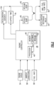
Figure 2 , with continued reference toFigure 1 , theengine controller 38 includes aprocessor 46 and amemory device 48. Theexample controller 38 relates to a device and system for performing necessary computing or calculation operations. Thecontroller 38 may be specially constructed or it may comprise at least a general-purpose computer selectively activated or reconfigured bysoftware instructions 50 stored in thememory device 48. Thememory device 48 further includes areslam logic 52 that includes instructions that are performed by theprocessor 46 for determining a debit to engine operation in response to detection of a reslam operation. Thecontroller 38 may further be part of full authority digital engine control (FADEC) or an electronic engine controller (EEC). - The disclosed
memory device 48, may include any one or combination of volatile memory elements (e.g., random access memory (RAM, such as DRAM, SRAM, SDRAM, VRAM, etc.) and/or nonvolatile memory elements (e.g., ROM, hard drive, tape, CD-ROM, etc.). Thesoftware instructions 50 in thememory device 48 may include one or more separate programs, each of which includes an ordered listing of executable instructions for implementing logical functions. Software in memory, in whole or in part, is read by theprocessor 46, and executed to generate debit limits. Theexample engine controller 38 includes all devices that operate to communicate with theengine assembly 20 to generate the thrust based on debits determined by theprocessor 46 utilizing theexample reslam logic 52. - The
engine controller 38 receives information relating toengine speed 54,ambient conditions 56 andfuel flow rate 58, among other information. Theengine controller 38 determines thedefault debit 60 and/or areslam debit 62 that is applied to anacceleration reference value 64 and a maximumfuel flow rate 66. The applied debit places a limit on each of theacceleration reference value 64 and the maximumfuel flow rate 66 to limit engine operation. The exampleacceleration reference value 64 may be speed of anengine shaft 2 as provided by aspeed sensor 34, or other measured engine speeds that are indicative of engine operation. The maximumfuel flow rate 66 is based on an output command to control actuation of thefuel system 32 to limit fuel flow and is not typically measured. However, it is within the contemplation of this disclosure that theflow rate 66 may be measured by theflow sensor 44. - Referring to
Figure 3 , with continued reference toFigure 2 , thereslam logic 52 is necessary on gas turbine engines that are susceptible to stalls/surges during a rapid increase in power/thrust request following a rapid decrease in power/thrust request with little or no stabilization time. A reslam operation is asharp deceleration 74 ofengine speed 70, and thereforeengine power 72 followed after a short elapsedtime 78 by arapid acceleration demand 76. Engines are not re-slammed at the same acceleration rate as may be conducted during normal engine rapid accelerations because of the impact of transient heat transfer, lagging engine variable geometries and stabilizing clearances in the turbomachinery that are susceptible to thermal changes. - The different phases of an example reslam operation are shown in the
graph 68 shown inFigure 3 . Engine surges and exceedances are caused by the nominal engine coreacceleration reference value 64 being too high for the reslam condition. Theexample reslam logic 52 temporarily debits, or limits, theacceleration reference value 64 and the maximumfuel flow rate 66 once adeceleration 74 condition is detected to prevent the engine from surging/exceeding limit on the subsequent acceleration. - The example a
reslam logic 52 debits both theAcceleration reference value 64 and the maximum fuel flow rate ofchange 66. Theexample reslam logic 52 modulates the magnitude of thereslam debit 62 based an elapsedtime 78 from the moment when the deceleration condition is detected and the reslam logic is activated. Thereslam debit 62 is inversely proportional to the elapsed time from the triggering of thereslam logic 52. In other words, the shorter the elapsed time between the deceleration and a subsequent acceleration demand, the larger thereslam debit 62. Moreover, the longer the elapsed time between the initial deceleration, the smaller thereslam debit 62. - The
reslam debit 62 is also modulated based on a magnitude of the deceleration that triggered thereslam logic 52. For example, a more aggressive deceleration would incur a larger debit as compared to a less aggressive deceleration. The magnitude of the deceleration is determined as adeceleration severity debit 102. In one example embodiment, thedeceleration severity debit 102 is based on a ratio between the maximum detected deceleration and a nominal deceleration reference. The nominal deceleration reference may be predefined in a look-up table for current engine operating conditions. - Referring to
Figures 4 and5 with continued reference toFigure 2 , steps of anexample reslam logic 52 embodiment is shown in aflow chart 80 inFigure 4 andgraph 94 inFigure 5 . Anengine acceleration 96 is shown as a ratio of measured acceleration and measured deceleration relative to their respective reference values over time. Thereslam logic 52 is triggered after an initial deceleration prompted by a pilot as shown at 98. Once the deceleration continues past a reslam logic trigger threshold 104 (Figure 5 ), thereslam logic 52 is triggered as a deceleration exceeding thethreshold 104 and a timer started. - The deceleration that prompts the reslam logic may be detected in other ways and remain within the contemplation and scope of this disclosure. For example, deceleration that prompts the reslam logic may also be based on various engine and ambient conditions. For example, a deceleration lower than a defined percent of a measured speed could be used to trigger the reslam logic to debit engine performance.
- The deceleration continues to a maximum point as indicated at 100. At the
point 100, a severity of the deceleration is determined. In one disclosed example, the severity of the deceleration is quantified as thedeceleration severity debit 102. - Once an acceleration is detected as indicated at 84 in the
flow chart 80, the elapsedtime 78 is determined. In one example embodiment, acceleration is detected based on passing anacceleration threshold 106 shown ingraph 94. The elapsed time is the time between triggering of the reslam logic based on the deceleration indicated at 98 and detection of the acceleration past the threshold as indicated at 84. The elapsed time is utilized to determine an elapsed time debit as indicated at 86. Additionally, ambient conditions are considered along with the elapsed time to determine an elapsed time debit value. In one example embodiment, the longer the elapsed time, the lower the debit. The ambient conditions are considered and modify the elapsed time debit value based on predefined conditions including ambient temperatures. The more extreme the ambient conditions, the greater the debit. - The
deceleration severity debit 102 modifies the elapsed time debit indicated at 86 to provide a final debit indicted at 88. Thedeceleration severity debit 102 modifies the final debit to factor in extreme engine operation. Higher severity will lengthen the final engine acceleration response time. The deceleration severity debit evaluation is not limited to a ratio (of the deceleration on the deceleration reference, but could also be function of the minimum or the average measured past deceleration. That relationship could vary based on various engine and ambient conditions. - Once the final debit is determined as indicated at 88 in
Figure 4 , theacceleration reference value 64 and the maximumfuel rate value 66 will be debited to set limits on engine acceleration as indicated at 90. Theengine 20 is then operated within the reduced limits for a predefined time period. The predefined time period is determined as that duration needed for the engine to regain thermal equilibrium that allows for operation under the default debits. The default debits are based on common engine operation, such as for example ambient conditions. Once the predefined time period expires, the reslam debits are removed and the default debits applied to the acceleration reference value and the maximum fuel flow rate as indicated at 92. - Referring to
Figure 6 ,graph 108 illustrates the inversely proportional relationship between thereslam debit 62 and the elapsedtime 78. Thedebit 62 decreases as the elapsedtime 78 increases as shown byline 110. Although theline 110 is shown by way of example as a linear trend, the rate that the debit is increased or decreased relative to the elapsedtime 78 may vary non-linearly. Moreover, the shape and magnitude of thedebit 62 may vary based on ambient conditions such as, for example, altitude, temperature, aircraft speed and/or, engine speed/power. - In the disclosed example shown in
graph 108, the end of the reslam debit indicated at 112 is shown at a fixed elapsed time and thereslam debit 62 is shown as being constant for the entire elapsedtime 78. - Referring to
Figure 7 ,graph 114 shows an example of how thereslam debit 62 is modulated based on the elapsedtime 78 from triggering of the logic as indicated at 82 and a subsequent acceleration. Thegraph 114 shows thecore speed 128 overtime 78. The start of the initial deceleration indicated at 98 and triggering of the reslam logic indicated at 82 are the same. In a first example, the elapsed time 116 is relatively short between trigger of thereslam logic 82 and subsequent acceleration indicated at 124. The subsequent acceleration from thepoint 124 is indicated at 120. In a second example, subsequent acceleration indicated at 122 does not occur for a longer elapsed time indicated at 118. In the second example, acceleration does not begin until thepoint 126. Accordingly, the acceleration indicated by 122 is not as limited as compared to the acceleration indicated byline 120. The second acceleration 122 re-accelerates sooner after the reslam debit than thefirst acceleration 120. - Referring to
Figure 8 , in another example embodiment illustrated bygraph 130, areslam debit 132 overtime 134 that is determined for each of a plurality of intervals within the elapsedtime 134. Instead of maintaining a fixed reslam debit as is shown inFigure 6 , theexample debit 138 varies from the reslam logic trigger indicated at 136 and a time when thedebit 138 is zero as indicated at 140. The intervals are of a predefined duration and provide for varying reslam debit that decreases over time. Furthermore, the intervals may, for example, be set to correspond with a loop refresh loop rate at thecontroller 38, EEC or the FADEC. - Accordingly, in this example embodiment, for each interval, a reslam debit is determined using a predefined relationship that decreases the debit with elapsed time. The decreasing reslam debit could be implemented by a table or an equation. At each interval, the reslam debit is modified in view of the deceleration severity debit to obtain a final debit for that time interval. For example, this could be done by multiplying both debits together. The final debit is used to reduce the engine acceleration reference and the maximum fuel flow rate for that time interval. The process is repeated for each time interval until the final debit is zero as shown at 140. The
variable reslam debit 138 shown inFigure 8 is one example of how the reslam debit may vary. - Referring to
Figure 9 ,graph 150 illustrates example varyingreslam debits 132 overtime 134. In one example, the reslam debit shown byline 142 remains constant for a first period and then decreases linearly until reaching zero as indicated at 152. - In another example, the reslam debit shown by
line 144 decreases according to an exponential function. In another example, thereslam debit 146 decreases in a stepped fashion. In another example, the reslam debit decreases according to a constant slope as shown byline 148. In still another example, the reslam debit may decrease according to theline 138. Accordingly, the time-varyingreslam debit 132 could be of any shape and magnitude. Moreover, each of the disclosed example rates may be further modified based on ambient conditions such as for example, altitude, temperature, aircraft speed and/or engine speed/power. - The example method debits the maximum fuel rate to enable maximizing acceleration while protecting against engine instability/exceedance at the beginning of the acceleration. Protecting the engine by using only the acceleration reference value may impact more of any the subsequent acceleration time than also using the maximum fuel flow rate.
- A method of controlling an aircraft engine with an engine control system for limiting acceleration in response to reslam operation, the method according to an exemplary embodiment of this disclosure, among other possible things includes triggering a
reslam logic 52, detecting an acceleration that exceeds anacceleration threshold 106, determining an elapsed time debit based on time elapsed from triggering of thereslam logic 52, the elapsed time debit is inversely proportional to the elapsedtime 78 from triggering of thereslam logic 52, determining adebit 62 based at least partially on the elapsed time debit, setting an engine acceleration reference value limit and maximum fuel rate limit based on thedebit 62, and operating the engine within the set acceleration value limit and the fuel rate limit. - In a further embodiment of the foregoing, the method further includes removing the
debit 62 from the acceleration value limit and the fuel rate limit in response to an elapsedtime 78 from the triggering of thereslam logic 52 that exceeds a predefined duration. - In a further embodiment of any of the foregoing, the method further includes returning limits to the
acceleration reference value 64 and the fuel rate to non-debited limits at a predefined rate after the predefined duration. - In a further embodiment of any of the foregoing methods, the
reslam logic 52 is triggered in response to a detected deceleration that exceeds a predefined threshold. - In a further embodiment of any of the foregoing, the method further includes quantifying a severity of the detected deceleration as a severity metric and determining the debit based on a combination of the elapsed time debit and the severity metric.
- In a further embodiment of any of the foregoing methods, the severity metric is based on a maximum absolute ratio of the detected deceleration to a nominal deceleration reference value.
- In a further embodiment of any of the foregoing methods, the elapsed time debit is further determined based in part on ambient conditions.
- In a further embodiment of any of the foregoing, the method further includes determined the elapsed time debit as a constant for the predefined duration.
- In a further embodiment of any of the foregoing, the method further includes determining the elapsed time debit separately for each of a plurality of time intervals beginning from the triggering of the
reslam logic 52 to the predefined duration. - In a further embodiment of any of the foregoing, the detected deceleration is based on a measured core speed deceleration reaching a predefined threshold.
- A control system for an aircraft engine according to another exemplary embodiment of this disclosure, among other possible things includes a
controller 38 that includes aprocessor 46 and amemory 48 for setting acceleration limits of an engine during reslam operation, thecontroller 38 is programmed to trigger operation of areslam logic 52, to detect an acceleration that exceeds an acceleration threshold, to determine an elapsed time debit based on time elapsed from triggering of thereslam logic 52, the elapsed time debit is inversely proportional to the elapsed time from triggering of thereslam logic 52, to determine a debit based at least partially on the elapsed time debit, setting an engine acceleration reference value limit and maximum fuel rate limit based on the debit, to operate the engine within the set acceleration value limit and the fuel rate limit, and to return limits to theacceleration reference value 64 and the fuel rate to a non-debited limit after the predefined duration. - In a further embodiment of the foregoing, the control system further includes returning limits to the
acceleration reference value 64 and the fuel rate to non-debited limits at a predefined rate after the predefined duration. - In a further embodiment of any of the foregoing control systems, the
reslam logic 52 is triggered in response to a detected deceleration that exceeds a predefined threshold. - In a further embodiment of any of the foregoing control systems, the
controller 38 is further programmed to quantify a severity of the detected deceleration as a severity metric and to determine the debit based on a combination of the elapsed time debit and the severity metric. - In a further embodiment of any of the foregoing control systems, the
controller 38 is further programmed to determine the elapsed time debit as a constant for the predefined duration. - In a further embodiment of any of the foregoing control systems, the
controller 38 is further programmed to determine the elapsed time debit separately for each of a plurality of time intervals beginning from the triggering of thereslam logic 52 to the predefined duration. - An aircraft engine assembly according to another exemplary embodiment of this disclosure, among other possible things includes a core engine that includes a
compressor section 24 where an inlet airflow is compressed, acombustor section 26 where the compressed inlet airflow is mixed with fuel and ignited to generate an exhaust gas flow that is communicated through a core flow path and aturbine section 28 where expansion of the exhaust gas flow is utilized to generate a mechanical power output. An engine control system includes acontroller 38 that has aprocessor 46 and amemory 48 that includes instruction that is executed by theprocessor 46 for setting acceleration limits of the core engine during reslam operation. Thecontroller 38 is programmed to trigger operation of areslam logic threshold 52, to detect an acceleration that exceeds an acceleration threshold, to determine an elapsed time debit based on time elapsed from triggering of thereslam logic 52, the elapsed time debit is inversely proportional to the elapsed time from triggering of thereslam logic 52, to determine a constant debit based at least partially on the elapsed time debit, setting an engine acceleration reference value limit and maximum fuel rate limit based on the constant debit, to operate the engine within the set acceleration value limit and the fuel rate limit, and to return limits to theacceleration reference value 64 and the fuel rate to a non-debited limit after the predefined duration. - In a further embodiment of the foregoing, the
controller 38 is further programmed to quantify a severity of a detected deceleration as a severity metric and to determine the constant debit based on a combination of the elapsed time debit and the severity metric. - In a further embodiment of any of the foregoing aircraft engine assemblies, the
controller 38 is further programmed to determine the elapsed time debit as a constant for the predefined duration. - In a further embodiment of any of the foregoing aircraft engine assemblies, the
controller 38 is further programmed to determine the elapsed time debit separately for each of a plurality of time intervals beginning from the triggering of thereslam logic 52 to the predefined duration. - A disclosed example embodiment of the reslam logic is implemented as part of an electronic engine controller (EEC) and is therefore enables simpler incorporation as compared to complex reslam logics where the debit is varying based on measured thermal recovery. The disclosed example reslam logic doesn't require measurements indicative of a thermal state of the engine.
- Although an example embodiment has been disclosed, a worker of ordinary skill in this art would recognize that certain modifications would come within the scope of this disclosure. For that reason, the following claims should be studied to determine the scope and content of this disclosure.
Claims (15)
- A method of controlling an aircraft engine with an engine control system for limiting acceleration in response to reslam operation, the method comprising:triggering a reslam logic (52);detecting an acceleration exceeding an acceleration threshold (106);determining an elapsed time debit based on time elapsed (78) from triggering of the reslam logic (52), wherein the elapsed time debit is inversely proportional to the elapsed time (78) from triggering of the reslam logic (52);determining a debit (62) based at least partially on the elapsed time debit;setting an engine acceleration reference value limit and maximum fuel rate limit based on the debit (62); andoperating the engine (20) within the set acceleration value limit and the fuel rate limit.
- The method as recited in claim 1, further comprising removing the debit (62) from the acceleration value limit and the fuel rate limit in response to an elapsed time (78) from the triggering of the reslam logic (52) exceeding a predefined duration.
- The method as recited in claim 2, further comprising returning limits to the acceleration reference value (64) and the fuel rate to non-debited limits at a predefined rate after the predefined duration.
- The method as recited in any claim 2 or 3, further comprising determined the elapsed time debit:as a constant for the predefined duration; and/orseparately for each of a plurality of time intervals beginning from the triggering of the reslam logic (52) to the predefined duration.
- The method as recited in any preceding claim, wherein the reslam logic (52) is triggered in response to a detected deceleration (74) that exceeds a predefined threshold.
- The method as recited in claim 5, further comprising quantifying a severity of the detected deceleration (74) as a severity metric and determining the debit (62) based on a combination of the elapsed time debit and the severity metric, optionally wherein the severity metric is based on a maximum absolute ratio of the detected deceleration (74) to a nominal deceleration reference value.
- The method as recited in claim 5 or 6, wherein the detected deceleration (74) is based on a measured core speed deceleration reaching a predefined threshold.
- The method as recited in any preceding claim, wherein the elapsed time debit is further determined based in part on ambient conditions.
- A control system for an aircraft engine comprising:
a controller (38) including a processor (46) and a memory (48) for setting acceleration limits of an engine (20) during reslam operation, wherein the controller (38) is programmed:to trigger operation of a reslam logic (52);to detect an acceleration exceeding an acceleration threshold (106);to determine an elapsed time debit based on time elapsed from triggering of the reslam logic (52), wherein the elapsed time debit is inversely proportional to the elapsed time (78) from triggering of the reslam logic (52);to determine a debit (62) based at least partially on the elapsed time debit;setting an engine acceleration reference value limit and maximum fuel rate limit based on the debit (62);to operate the engine (20) within the set acceleration value limit and the fuel rate limit; andto return limits to the acceleration reference value (64) and the fuel rate to a non-debited limit after a predefined duration. - The control system as recited in claim 9, further comprising returning limits to the acceleration reference value (64) and the fuel rate to non-debited limits at a predefined rate after the predefined duration.
- The control system as recited in claim 9 or 10, wherein the reslam logic (52) is triggered in response to a detected deceleration (74) that exceeds a predefined threshold.
- An aircraft engine assembly comprising:a core engine including a compressor section where an inlet airflow is compressed, a combustor section where the compressed inlet airflow is mixed with fuel and ignited to generate an exhaust gas flow that is communicated through a core flow path and a turbine section where expansion of the exhaust gas flow is utilized to generate a mechanical power output; andthe engine control system of any preceding claim.
- The control system or aircraft engine assembly as recited in any of claims 9 to 12, wherein the controller (38) is further programmed to quantify a severity of a or the detected deceleration (74) as a severity metric and to determine the debit (62) based on a combination of the elapsed time debit and the severity metric.
- The control system or aircraft engine assembly as recited in any of claims 9 to 13, wherein the controller (38) is further programmed to determine the elapsed time debit as a constant for the predefined duration.
- The control system or aircraft engine assembly as recited in any of claims 9 to 14, wherein the controller (38) is further programmed to determine the elapsed time debit separately for each of a plurality of time intervals beginning from the triggering of the reslam logic (52) to the predefined duration.
Applications Claiming Priority (1)
| Application Number | Priority Date | Filing Date | Title |
|---|---|---|---|
| US18/343,927 US12140087B1 (en) | 2023-06-29 | 2023-06-29 | Time varying reslam logic for acceleration reference and maximum fuel flow rate |
Publications (1)
| Publication Number | Publication Date |
|---|---|
| EP4484732A1 true EP4484732A1 (en) | 2025-01-01 |
Family
ID=91759559
Family Applications (1)
| Application Number | Title | Priority Date | Filing Date |
|---|---|---|---|
| EP24185771.3A Pending EP4484732A1 (en) | 2023-06-29 | 2024-07-01 | Time varying reslam logic for acceleration reference and maximum fuel flow rate |
Country Status (3)
| Country | Link |
|---|---|
| US (1) | US12140087B1 (en) |
| EP (1) | EP4484732A1 (en) |
| CA (1) | CA3244612A1 (en) |
Citations (3)
| Publication number | Priority date | Publication date | Assignee | Title |
|---|---|---|---|---|
| US4432201A (en) * | 1981-01-14 | 1984-02-21 | Aviation Electric Ltd. | Acceleration limit reset |
| US4442667A (en) * | 1981-01-14 | 1984-04-17 | Aviation Electric Ltd. | Acceleration limit reset |
| GB2218537A (en) * | 1988-05-11 | 1989-11-15 | Rolls Royce Plc | Engine control |
Family Cites Families (2)
| Publication number | Priority date | Publication date | Assignee | Title |
|---|---|---|---|---|
| US3772882A (en) | 1971-12-02 | 1973-11-20 | Lucas Industries Ltd | Fuel control systems for gas turbine engines |
| EP3351771B1 (en) | 2017-01-20 | 2021-03-17 | GE Avio S.r.l. | Gas turbine engine fuel control system and method |
-
2023
- 2023-06-29 US US18/343,927 patent/US12140087B1/en active Active
-
2024
- 2024-06-27 CA CA3244612A patent/CA3244612A1/en active Pending
- 2024-07-01 EP EP24185771.3A patent/EP4484732A1/en active Pending
Patent Citations (3)
| Publication number | Priority date | Publication date | Assignee | Title |
|---|---|---|---|---|
| US4432201A (en) * | 1981-01-14 | 1984-02-21 | Aviation Electric Ltd. | Acceleration limit reset |
| US4442667A (en) * | 1981-01-14 | 1984-04-17 | Aviation Electric Ltd. | Acceleration limit reset |
| GB2218537A (en) * | 1988-05-11 | 1989-11-15 | Rolls Royce Plc | Engine control |
Also Published As
| Publication number | Publication date |
|---|---|
| US12140087B1 (en) | 2024-11-12 |
| CA3244612A1 (en) | 2025-06-06 |
Similar Documents
| Publication | Publication Date | Title |
|---|---|---|
| US7584618B2 (en) | Controlling air flow to a turbine shroud for thermal control | |
| US9988987B2 (en) | Method of starting a turbomachine while reducing thermal unbalance | |
| US6735951B2 (en) | Turbocharged auxiliary power unit with controlled high speed spool | |
| US4117668A (en) | Stall detector for gas turbine engine | |
| EP2843198B1 (en) | Method and control system for active rotor tip control clearance | |
| US6820429B2 (en) | Adaptive acceleration schedules for gas turbine engine control systems | |
| EP1013891B1 (en) | Method and apparatus for use in control and compensation of clearances in a gas turbine engine | |
| JP2000064856A (en) | Controller for operating bleed valve and method for controlling operation of bleed valve | |
| CA2826299C (en) | Compressor surge prevention digital system | |
| US20200284265A1 (en) | Application of Machine Learning to Process High-Frequency Sensor Signals of a Turbine Engine | |
| EP3712074B1 (en) | Method and system for setting power of an aircraft engine | |
| US11131211B2 (en) | Method and system for setting an acceleration schedule for engine start | |
| US11022048B2 (en) | Method and a device for controlling thrust from a turbojet | |
| EP3409926B1 (en) | Method and system for detecting a high temperature condition of a gas turbine | |
| US5267435A (en) | Thrust droop compensation method and system | |
| US5259188A (en) | Method and system to increase stall margin | |
| US10302021B2 (en) | Detection of uncommanded and uncontrollable high thrust events | |
| US12140087B1 (en) | Time varying reslam logic for acceleration reference and maximum fuel flow rate | |
| JP2004003474A (en) | How to extend the life of a gas turbine engine. | |
| CN113544373A (en) | Method for regulating the exhaust gas temperature of a turbomachine | |
| EP3623608B1 (en) | Method and system for adjusting a variable geometry mechanism | |
| EP4148256B1 (en) | Output power management for engines | |
| JP3314428B2 (en) | Fan stall prevention device | |
| CN116804380A (en) | Method and apparatus for cooling turbine blades | |
| US20250146443A1 (en) | Blended n-dot and ratio unit reference acceleration control architecture for gas turbine engine |
Legal Events
| Date | Code | Title | Description |
|---|---|---|---|
| PUAI | Public reference made under article 153(3) epc to a published international application that has entered the european phase |
Free format text: ORIGINAL CODE: 0009012 |
|
| STAA | Information on the status of an ep patent application or granted ep patent |
Free format text: STATUS: THE APPLICATION HAS BEEN PUBLISHED |
|
| AK | Designated contracting states |
Kind code of ref document: A1 Designated state(s): AL AT BE BG CH CY CZ DE DK EE ES FI FR GB GR HR HU IE IS IT LI LT LU LV MC ME MK MT NL NO PL PT RO RS SE SI SK SM TR |
|
| STAA | Information on the status of an ep patent application or granted ep patent |
Free format text: STATUS: REQUEST FOR EXAMINATION WAS MADE |
|
| 17P | Request for examination filed |
Effective date: 20250701 |