EP4484725A1 - Aircraft propulsion system with turbine engine exhaust heat exchanger - Google Patents
Aircraft propulsion system with turbine engine exhaust heat exchanger Download PDFInfo
- Publication number
- EP4484725A1 EP4484725A1 EP24185535.2A EP24185535A EP4484725A1 EP 4484725 A1 EP4484725 A1 EP 4484725A1 EP 24185535 A EP24185535 A EP 24185535A EP 4484725 A1 EP4484725 A1 EP 4484725A1
- Authority
- EP
- European Patent Office
- Prior art keywords
- conduit
- fluid
- heat exchanger
- inter
- exhaust gas
- Prior art date
- Legal status (The legal status is an assumption and is not a legal conclusion. Google has not performed a legal analysis and makes no representation as to the accuracy of the status listed.)
- Pending
Links
Images




Classifications
-
- F—MECHANICAL ENGINEERING; LIGHTING; HEATING; WEAPONS; BLASTING
- F02—COMBUSTION ENGINES; HOT-GAS OR COMBUSTION-PRODUCT ENGINE PLANTS
- F02C—GAS-TURBINE PLANTS; AIR INTAKES FOR JET-PROPULSION PLANTS; CONTROLLING FUEL SUPPLY IN AIR-BREATHING JET-PROPULSION PLANTS
- F02C3/00—Gas-turbine plants characterised by the use of combustion products as the working fluid
- F02C3/20—Gas-turbine plants characterised by the use of combustion products as the working fluid using a special fuel, oxidant, or dilution fluid to generate the combustion products
- F02C3/22—Gas-turbine plants characterised by the use of combustion products as the working fluid using a special fuel, oxidant, or dilution fluid to generate the combustion products the fuel or oxidant being gaseous at standard temperature and pressure
-
- F—MECHANICAL ENGINEERING; LIGHTING; HEATING; WEAPONS; BLASTING
- F02—COMBUSTION ENGINES; HOT-GAS OR COMBUSTION-PRODUCT ENGINE PLANTS
- F02C—GAS-TURBINE PLANTS; AIR INTAKES FOR JET-PROPULSION PLANTS; CONTROLLING FUEL SUPPLY IN AIR-BREATHING JET-PROPULSION PLANTS
- F02C7/00—Features, components parts, details or accessories, not provided for in, or of interest apart form groups F02C1/00 - F02C6/00; Air intakes for jet-propulsion plants
- F02C7/08—Heating air supply before combustion, e.g. by exhaust gases
- F02C7/10—Heating air supply before combustion, e.g. by exhaust gases by means of regenerative heat-exchangers
-
- F—MECHANICAL ENGINEERING; LIGHTING; HEATING; WEAPONS; BLASTING
- F02—COMBUSTION ENGINES; HOT-GAS OR COMBUSTION-PRODUCT ENGINE PLANTS
- F02C—GAS-TURBINE PLANTS; AIR INTAKES FOR JET-PROPULSION PLANTS; CONTROLLING FUEL SUPPLY IN AIR-BREATHING JET-PROPULSION PLANTS
- F02C7/00—Features, components parts, details or accessories, not provided for in, or of interest apart form groups F02C1/00 - F02C6/00; Air intakes for jet-propulsion plants
- F02C7/22—Fuel supply systems
- F02C7/224—Heating fuel before feeding to the burner
-
- F—MECHANICAL ENGINEERING; LIGHTING; HEATING; WEAPONS; BLASTING
- F28—HEAT EXCHANGE IN GENERAL
- F28D—HEAT-EXCHANGE APPARATUS, NOT PROVIDED FOR IN ANOTHER SUBCLASS, IN WHICH THE HEAT-EXCHANGE MEDIA DO NOT COME INTO DIRECT CONTACT
- F28D21/00—Heat-exchange apparatus not covered by any of the groups F28D1/00 - F28D20/00
- F28D21/0001—Recuperative heat exchangers
- F28D21/0003—Recuperative heat exchangers the heat being recuperated from exhaust gases
-
- F—MECHANICAL ENGINEERING; LIGHTING; HEATING; WEAPONS; BLASTING
- F28—HEAT EXCHANGE IN GENERAL
- F28D—HEAT-EXCHANGE APPARATUS, NOT PROVIDED FOR IN ANOTHER SUBCLASS, IN WHICH THE HEAT-EXCHANGE MEDIA DO NOT COME INTO DIRECT CONTACT
- F28D7/00—Heat-exchange apparatus having stationary tubular conduit assemblies for both heat-exchange media, the media being in contact with different sides of a conduit wall
- F28D7/10—Heat-exchange apparatus having stationary tubular conduit assemblies for both heat-exchange media, the media being in contact with different sides of a conduit wall the conduits being arranged one within the other, e.g. concentrically
- F28D7/103—Heat-exchange apparatus having stationary tubular conduit assemblies for both heat-exchange media, the media being in contact with different sides of a conduit wall the conduits being arranged one within the other, e.g. concentrically consisting of more than two coaxial conduits or modules of more than two coaxial conduits
-
- F—MECHANICAL ENGINEERING; LIGHTING; HEATING; WEAPONS; BLASTING
- F05—INDEXING SCHEMES RELATING TO ENGINES OR PUMPS IN VARIOUS SUBCLASSES OF CLASSES F01-F04
- F05D—INDEXING SCHEME FOR ASPECTS RELATING TO NON-POSITIVE-DISPLACEMENT MACHINES OR ENGINES, GAS-TURBINES OR JET-PROPULSION PLANTS
- F05D2260/00—Function
- F05D2260/20—Heat transfer, e.g. cooling
- F05D2260/213—Heat transfer, e.g. cooling by the provision of a heat exchanger within the cooling circuit
-
- F—MECHANICAL ENGINEERING; LIGHTING; HEATING; WEAPONS; BLASTING
- F05—INDEXING SCHEMES RELATING TO ENGINES OR PUMPS IN VARIOUS SUBCLASSES OF CLASSES F01-F04
- F05D—INDEXING SCHEME FOR ASPECTS RELATING TO NON-POSITIVE-DISPLACEMENT MACHINES OR ENGINES, GAS-TURBINES OR JET-PROPULSION PLANTS
- F05D2260/00—Function
- F05D2260/20—Heat transfer, e.g. cooling
- F05D2260/221—Improvement of heat transfer
-
- F—MECHANICAL ENGINEERING; LIGHTING; HEATING; WEAPONS; BLASTING
- F28—HEAT EXCHANGE IN GENERAL
- F28D—HEAT-EXCHANGE APPARATUS, NOT PROVIDED FOR IN ANOTHER SUBCLASS, IN WHICH THE HEAT-EXCHANGE MEDIA DO NOT COME INTO DIRECT CONTACT
- F28D21/00—Heat-exchange apparatus not covered by any of the groups F28D1/00 - F28D20/00
- F28D2021/0019—Other heat exchangers for particular applications; Heat exchange systems not otherwise provided for
- F28D2021/0021—Other heat exchangers for particular applications; Heat exchange systems not otherwise provided for for aircrafts or cosmonautics
Definitions
- This disclosure relates to an aircraft in general, and to a turbine engine system for an aircraft in particular.
- Turbine engines typically exhaust high temperature gas during operation. Once exhausted, that high temperature gas and its inherent energy is lost. It would be desirable to recuperate the inherent energy within the exhaust to improve the performance of the turbine engine, including the Brayton cycle performance of the turbine engine.
- an aircraft propulsion system includes a turbine engine and an exhaust gas heat exchanger.
- the turbine engine is configured to produce exhaust gases during combustion.
- the exhaust gas heat exchanger extends axially along a central axis between a forward end and an aft end, and is disposed to receive exhaust gases from the turbine engine.
- the exhaust gas heat exchanger includes a central conduit, an outer radial plenum, a plurality of fluid conduits, and a plurality of inter-conduit passages.
- the fluid conduits are disposed in a nested arrangement. Each fluid conduit has an inner and an outer radial wall that each extend axially between the forward and aft ends.
- the inner radial wall is radially separated from the outer radial wall to form an internal fluid passage therebetween.
- Each fluid conduit is radially spaced apart from adjacent fluid conduits to define an axially extending exhaust gas passage disposed between adjacent fluid conduits.
- the inter-conduit passages include at least one inter-conduit passage configured to provide fluid communication between the central conduit and a first fluid conduit, and at least one inter-conduit passage that is configured to provide fluid communication between the first fluid conduit and a second fluid conduit.
- a serpentine fluid flow path extends through the fluid conduits and the inter-conduit passages.
- the exhaust gas heat exchanger may be disposed relative to the turbine engine such that the exhaust gases from the turbine engine enter the forward end of the exhaust gas heat exchanger, pass through the exhaust gas passages disposed between adjacent fluid conduits, and exit the aft end of the exhaust gas heat exchanger.
- each fluid conduit may have an axially extending cylindrical configuration.
- each fluid conduit may have a circular cross-sectional geometry.
- the circular cross-sectional geometry may extend at a constant radius.
- the circular cross-sectional geometry may extend circumferentially in a wavy configuration.
- the plurality of fluid conduits disposed in a nested arrangement may be concentric with one another.
- the plurality of inter-conduit passages may include a first set of inter-conduit passages disposed at a first circumferential position, and a second set of inter-conduit passages disposed at a second circumferential position.
- At least one inter-conduit passage within the first set of inter-conduit passages may be disposed adjacent to the forward end of the heat exchanger at the first circumferential position, and at least one inter-conduit passage within the first set of inter-conduit passages may be disposed adjacent to the aft end of the heat exchanger at the first circumferential position.
- At least one inter-conduit passage within the second set of inter-conduit passages may be disposed adjacent to the forward end of the heat exchanger at the second circumferential position, and at least one inter-conduit passage within the second set of inter-conduit passages may be disposed adjacent to the aft end of the heat exchanger at the second circumferential position.
- each fluid conduit has a circumference
- the internal fluid passage of each fluid conduit may be configured to have a first circumferential segment and a second circumferential segment, the first circumferential segment and the second circumferential segment fluidly isolated from one another, and the first set of inter-conduit passages may be in fluid communication with the first circumferential segment, and the second set of inter-conduit passages may be in fluid communication with the second circumferential segment.
- the central conduit may be disposed radially inside of the fluid conduits, and the outer radial plenum may be disposed radially outside of the fluid conduits, and the serpentine fluid flow path may extend through the central conduit, the fluid conduits, the inter-conduit passages, and the outer radial plenum.
- the system may include a flow expansion section disposed between a turbine section exit of the turbine engine and the exhaust gas heat exchanger, wherein the turbine section exit may have a first diameter and the exhaust gas heat exchanger may have a second diameter, wherein the second diameter is greater than the first diameter, and the flow expansion section may provide a flow transition boundary between the turbine section exit and the exhaust gas heat exchanger.
- one or more of the exhaust gas conduits may include a plurality of first heat transfer features that extend into a first flow path defined by the respective exhaust gas conduit.
- a turbine engine exhaust gas heat exchanger that extends along a central axis between a forward end and an aft end.
- the exhaust gas heat exchanger includes a central conduit, an outer radial plenum, a plurality of fluid conduits, and a plurality of inter-conduit passages.
- the fluid conduits are disposed in a nested arrangement.
- Each fluid conduit has an inner radial wall and an outer radial wall, each extending axially between the forward and aft ends.
- the inner radial wall is radially separated from the outer radial wall to form an internal fluid passage therebetween.
- Each fluid conduit is radially spaced apart from adjacent fluid conduits to define an axially extending exhaust gas passage disposed between adjacent fluid conduits.
- the inter-conduit passages include at least one inter-conduit passage that is configured to provide fluid communication between the central conduit and a first fluid conduit, and at least one inter-conduit passage that is configured to provide fluid communication between the first fluid conduit and a second fluid conduit.
- a serpentine fluid flow path extends through the fluid conduits and the inter-conduit passages.
- each fluid conduit has a cylindrical configuration that extends axially between the forward end and the aft end.
- the plurality of inter-conduit passages includes a first set of said inter-conduit passages disposed at a first circumferential position, and a second set of said inter-conduit passages disposed at a second circumferential position.
- At least one said inter-conduit passage within the first set of said inter-conduit passages is disposed adjacent to the forward end of the heat exchanger at the first circumferential position, and at least one said inter-conduit passage within the first set of said inter-conduit passages is disposed adjacent to the aft end of the heat exchanger at the first circumferential position.
- each fluid conduit has a circumference
- the internal fluid passage of each said fluid conduit is configured to have a first circumferential segment and a second circumferential segment, the first circumferential segment and the second circumferential segment fluidly isolated from one another.
- the first set of said inter-conduit passages are in fluid communication with the first circumferential segment
- the second set of said inter-conduit passages are in fluid communication with the second circumferential segment.
- the central conduit is disposed radially inside of the plurality of fluid conduits, and the outer radial plenum is disposed radially outside of the plurality of fluid conduits.
- the serpentine fluid flow path extends through the central conduit, the plurality of fluid conduits, the plurality of inter-conduit passages, and the outer radial plenum.
- FIG. 1 diagrammatically illustrates a present disclosure propulsion system 20 for an aircraft.
- the aircraft may be an airplane, a helicopter, a drone (e.g., an unmanned aerial vehicle (UAV)) or any other manned or unmanned aerial vehicle or system.
- the propulsion system 20 shown in FIG. 1 includes a propulsor rotor 22, a turbine engine 24, a fuel source 26, and an exhaust gas heat exchanger 28.
- an area expansion section 27 may be disposed axially forward of the exhaust gas heat exchanger 28.
- Non-limiting examples of a propulsor rotor 22 include a propeller rotor for a turboprop propulsion system, a rotorcraft rotor (e.g., a main helicopter rotor) for a turboshaft propulsion system, a propfan rotor for a propfan propulsion system, a pusher fan rotor for a pusher fan propulsion system, a fan for a turbofan propulsion system, or the like.
- a propeller rotor for a turboprop propulsion system e.g., a main helicopter rotor
- a rotorcraft rotor e.g., a main helicopter rotor
- a propfan rotor for a propfan propulsion system
- pusher fan rotor for a pusher fan propulsion system
- fan for a turbofan propulsion system or the like.
- the turbine engine 24 extends axially along an axis 30 between an upstream, forward end and a downstream, aft end.
- the turbine engine 24 includes a compressor section 32, a combustor section 34, and a turbine section 36.
- a reduction gearbox 37 provides drive communication between the engine 24 and the propulsor rotor 22.
- a core flow path 38 extends sequentially through the compressor section 32, the combustor section 34, and the turbine section 36. Air enters the turbine engine 24 through an airflow inlet 40 upstream of the compressor section 32, passes through the core flow path 38, and exits the turbine engine 24. Thereafter, the core gas enters the exhaust gas heat exchanger 28.
- the present disclosure is not limited to any particular turbine engine 24 configuration and the aforesaid description of the core flow path 38 and engine component positioning is for illustration purposes and is not intended to be limiting.
- Embodiments of the present disclosure propulsion system 20 may include a turbine engine 24 configured to combust non-hydrocarbon fuels (e.g., hydrogen or "H 2 "), or hydrocarbon fuels (e.g., aviation fuel), or some mixture thereof.
- non-hydrocarbon fuels e.g., hydrogen or "H 2 "
- hydrocarbon fuels e.g., aviation fuel
- the turbine engine 24 within a present disclosure system 20 embodiment may be configured to combust a fuel that is 100% non-hydrocarbon (e.g., 100% H 2 ), or a fuel that is 100% hydrocarbon (e.g., 100% aviation fuel), or a mixture thereof (e.g., a mixture of H 2 and aviation fuel).
- the present disclosure is not limited to any combusting any particular fuel.
- the fuel source 26 may be configured to store the hydrogen in liquid form and the present disclosure system 20 may be configured to process the hydrogen to a form (e.g., phase change to a gaseous phase) acceptable for combustion.
- a form e.g., phase change to a gaseous phase
- the non-hydrocarbon fluid may be one of the fluids that passes through the exhaust gas heat exchanger 28 with the other fluid being the turbine engine 24 exhaust gas.
- the heat recuperated from the turbine engine 24 exhaust gas may be used to change the non-hydrogen fuel from a cryogenic liquid state to a gaseous state.
- water in liquid form may be passed through the heat exchanger 28 to produce steam.
- steam may be injected into the combustor 34 to increase engine power and/or to reduce undesirable engine emissions.
- the exhaust gas heat exchanger 28 extends along a central axis 30 (e.g., coincident with the engine axis) between an exhaust gas inlet 42 and an exhaust gas outlet 44.
- the exhaust gas heat exchanger 28 may include a plurality of nested fluid conduits 46, a plurality of inter-conduit passages 48, a fluid port 50, a central conduit 52, and an outer radial plenum 54.
- the fluid port 50 (e.g., see FIG. 3 ) may be configured to provide fluid communication between a source of the fluid to be heated (e.g., non-hydrocarbon fuel, water, or the like) and the central conduit 52.
- the central conduit 52 is disposed centrally within the exhaust gas heat exchanger 28 (i.e., radially inside of the nested fluid conduits 46) and is in fluid communication with the radially innermost fluid conduit 46 of the nested fluid conduits 46.
- the outer radial plenum 54 may be an annular passage that extends around the entire outer circumference of the exhaust gas heat exchanger 28, or the outer radial plenum 54 may be a plurality of an annular passage segments that collectively extend around the substantially all the outer circumference of the exhaust gas heat exchanger 28, or the outer plenum may be a series of ports, or any combination thereof.
- Each nested fluid conduit 46 includes inner and outer radial walls 56, 58 that extend axially from between a forward end 60 of the heat exchanger 28 and an aft end 62 of the heat exchanger 28.
- the inner and outer radial walls 56, 58 of each fluid conduit 46 are radially spaced apart from one another to define an internal fluid passage 64 (e.g., see FIG. 3A ) therebetween.
- the inner and outer radial walls 56, 58 may be parallel with one another.
- Each fluid conduit 46 is closed at the forward end 60 and the aft end 62.
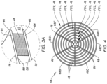
- FIG. 3A is an enlarged portion of the perspective view shown in FIG. 3 , showing a pair of fluid conduits 46 closed at the aft end 62.
- the nested fluid conduits 46 are disposed in a radial nested stack. Referring to FIG. 4 , one can see a first fluid conduit 46 (FC1) disposed radially inside of a second fluid conduit 46 (FC2), and the second fluid conduit 46 (FC2) is disposed radially inside of a third fluid conduit 46 (FC3), and so on up to an eighth fluid conduit 46 (FC8) being the radially outermost fluid conduit 46.
- FC1 disposed radially inside of a second fluid conduit 46 (FC2)
- FC3 third fluid conduit 46
- FC8 eighth fluid conduit 46
- the nested fluid conduits 46 are shown as having a cylindrical shape with a circular cross-sectional shape.
- Each fluid conduit 46 with a circular cross-sectional shape may be described as being collectively disposed at a radius; e.g., a constant radius wherein the outer radial wall 58 is disposed at a radius and the inner radial wall 56 is disposed at a radius.
- the present disclosure is not limited to nested fluid conduits 46 each having a cylindrical shape with a circular radiused cross-sectional shape.
- the fluid conduits 46 may extend cylindrically between the forward and aft ends 60, 62, but may have an alternative cross-sectional shape. FIG.
- FIGS. 2-5 diagrammatically illustrates a non-limiting example of an exhaust gas heat exchanger 28 that extends cylindrically and the fluid conduits 46 follow a wavy pattern (e.g., sinusoidal) circumferentially.
- a wavy pattern e.g., sinusoidal
- FIGS. 2-5 i.e., circular at respective radii, wavy, and the like
- FIGS. 2-5 are intended to be non-limiting examples.
- the nested fluid conduits 46 may be disposed in a concentric arrangement, and may be spaced equidistant from each other.
- the present disclosure is not limited to any particular nested geometry.
- each pair of adjacent fluid conduits 46 are in fluid communication with one another by means of one or more inter-conduit passages 48.
- the inter-conduit passages 48 are configured to permit fluid flow from a first fluid conduit 46 to pass through to an adjacent second fluid conduit 46.
- FIG. 6 diagrammatically illustrates a present disclosure exhaust gas heat exchanger 28 with the central conduit 52 in fluid communication a fluid port 50 and with a plurality of first inter-conduit passages 48.
- the central conduit 52 is in fluid communication with the fluid port 50 towards the aft end 62 of the heat exchanger 28 and in fluid communication with the first inter-conduit passages 48 towards the forward end 60 of the heat exchanger 28.
- the first inter-conduit passages 48 are in fluid communication with the radially innermost fluid conduit 46 (FC1).
- FC1 is in fluid communication with a plurality of second inter-conduit passages 48 disposed toward the aft end of FC1.
- the second inter-conduit passages 48 are in fluid communication with the adjacent fluid conduit 46 (FC2) disposed radially outside of FC1.
- FC2 is in fluid communication with a plurality of third inter-conduit passages 48 disposed toward the forward end of the FC2.
- the third inter-conduit passages 48 are in fluid communication with the adjacent fluid conduit 46 (FC3) disposed radially outside of FC2.
- the third inter-conduit passages 48 are in fluid communication with the adjacent fluid conduit 46 (FC4) disposed radially outside of the FC3.
- FC4 is in fluid communication with an outer radial plenum 54.
- the fluid conduits 46 and inter-conduit passages 48 are configured to form a serpentine fluid path between the fluid port 50 and the outer radial plenum 54.
- the radially innermost fluid conduit 46 is disposed outside of and spaced apart from the central conduit 52.
- the radially innermost fluid conduit 46 and the central conduit 52 define an exhaust gas passage 66 therebetween that extends axially from the forward end 60 to the aft end 62 of the heat exchanger 28.
- Each pair of adjacent fluid conduits 46 are spaced apart in similar manner to produce a plurality of exhaust gas passages 66 therebetween that extend axially between the forward and aft ends 60, 62 of the heat exchanger 28.
- the inter-conduit passages 48 may have an exterior configuration that is chosen to minimize fluid flow resistance (e.g., a substantially elliptical cross-sectional shape like that shown in FIG. 7 ), but the present disclosure is not limited to any particular inter-conduit passage 48 exterior configuration.
- the inter-conduit passages 48 are disposed at one or more circumferential positions.
- FIGS. 2-4 diagrammatically illustrate exhaust gas heat exchanger 28 embodiments having inter-conduit passages 48 disposed at six (6) circumferential positions.
- the circumferential spacing between inter-conduit passages 48 is symmetrical; i.e., the inter-conduit passages 48 are spaced apart from one another at sixty degree (60°) intervals.
- the present disclosure is not limited to disposing inter-conduit passages 48 at any particular number of circumferential positions, and does not require symmetrical spacing of the inter-conduit passages 48.
- the heat exchanger 28 may be configured with fluid conduits 46 that permit fluid flow around the entire circumference of the respective fluid conduit 46.
- the inter-conduit passages 48 disposed at the one or more circumferential positions each provide fluid communication for the entire circumference of the respective fluid conduits 46.
- the heat exchanger 28 may be configured with fluid conduits 46 configured to separate fluid flow into circumferential segments; e.g., two or more segments. Using the exhaust gas heat exchanger 28 embodiments diagrammatically shown in FIGS. 2-4 as an example, the fluid conduits 46 may be configured to separate fluid flow into six (6) circumferential segments 68A-F (e.g., see FIG.
- each segment in fluid communication with one of the six rows of inter-conduit passages 48 and each fluidly isolated from one another.
- fluid passing through the central conduit 52 enters into each circumferential segment via a respective inter-conduit passage 48 extending between the central conduit 52 and the respective segment of the radially innermost fluid conduit 46.
- the fluid passes thereafter through the respective fluid conduits 46 within the respective segment and subsequently passes into the outer radial plenum 54; e.g., following a serpentine fluid path.
- the diameter of the exhaust gas heat exchanger 28 may be greater that the diameter of a turbine section 36 exit of the turbine engine 24 disposed aft of the axially last turbine stage.
- the greater diameter of the exhaust gas heat exchanger 28 (and therefore cross-sectional area) may be chosen to increase the exhaust flow area through the heat exchanger 28 to account for cross-sectional area occupied by the fluid conduits 46 and thereby mitigate any flow impedance that may be associated with the exhaust gas heat exchanger 28 being disposed within the exhaust gas path.
- FIG. 1 illustrates an area expansion section 27 disposed axially between the turbine section 36 exit and the exhaust gas heat exchanger 28 configured to guide the exhaust gas flow into the larger diameter heat exchanger 28.
- exhaust gas heat exchanger 28 may include heat transfer members 70 extending into the exhaust gas passages 66; e.g., extending outwardly from the inner radial wall of one or more of the fluid conduits 46, or extending outwardly from the outer radial wall of one or more of the fluid conduits 46, or any combination thereof.
- FIG. 8 diagrammatically illustrates heat transfer members 70 extending out from the inner radial wall of a first fluid conduit 46 and heat transfer members 70 extending outwardly from the outer radial wall of an adjacent second fluid conduit 46. In the example diagrammatically shown in FIG.
- the heat transfer members 70 are configured as ribs that are axially aligned to minimize resistance to the exhaust gases flowing through the exhaust gas passages 66.
- the heat transfer members 70 are not limited to any particular configuration, and other heat transfer member configurations include pins and the like.
- the turbine engine 24 is operated to combust a fuel/air mixture to produce power.
- the produced exhaust gases exit the turbine section 36 aft of the axially last turbine stage and are either directly passed into the exhaust gas heat exchanger 28 or are passed through the area expansion section 27 prior to entering the exhaust gas heat exchanger 28.
- the exhaust gases subsequently travel axially through the exhaust gas passages 66 disposed between adjacent pairs of fluid conduits 46 and subsequently exit the heat exchanger 28.
- the exhaust gases exiting the heat exchanger 28 may exit directly to the exterior environment, or may pass through a nozzle section prior to exiting to the exterior environment.
- the nozzle section may be configured to utilize the exhaust gases to produce motive thrust in some applications.
- fluid from a fluid source may be supplied to the fluid port 50 of the heat exchanger 28. From there, the fluid passes into the central conduit 52. The fluid passes from the central conduit 52 to the radially innermost fluid conduit 46 via the one or more inter-conduit passages 48 providing fluid communication between the central conduit 52 and the radially innermost fluid conduit 46. The fluid thereafter travels throughout the fluid conduits 46 of the heat exchanger 28 until the fluid flow reaches the outer radial plenum 54. As described above, in some embodiments, the fluid path through the nested fluid conduits 46 may follow a serpentine path through the fluid conduits 46; e.g., see FIG. 6 .
- the present disclosure heat exchanger 28 is described above in configurations wherein the fluid to be heated enters the heat exchanger 28 centrally and moves collectively radially outward until it reaches the outer radial plenum 54.
- the present disclosure is not limited to this particular configuration.
- the fluid flow to be heated may be introduced to the heat exchanger 28 at the outer radial plenum 54 and the fluid path through the heat exchanger 28 may direct the fluid flow radially inward, where it may be collected within the central conduit 52.
- Embodiments of the present disclosure heat exchanger 28 are shown in the FIGURES in configurations wherein the fluid flow to be heated is introduced centrally (e.g., within the central conduit 52) and some number of fluid conduits 46 within a nested configuration are symmetrically spaced apart from one another.
- the present disclosure is not limited to these configurations.
- the present disclosure heat exchanger 28 may have a single fluid conduit 46.
- the present disclosure heat exchanger 28 may have a plurality of fluid conduits 46 within a nested configuration, and those fluid conduits 46 may be located in a particular radial region. For example, FIG.
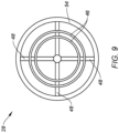
- FIG. 9 diagrammatically illustrates a present disclosure heat exchanger 28 having a pair of fluid conduits 46 in a nested configuration and the pair of fluid conduits 46 are disposed in a middle radial region of the heat exchanger 28.
- the pair of fluid conduits 46 may be disposed in an inner radial region of the heat exchanger 28, or in an outer radial region of the heat exchanger 28.
- any one of these structures may describe the operations as a sequential process, many of the operations can be performed in parallel or concurrently.
- the order of the operations may be rearranged.
- a process may correspond to a method, a function, a procedure, a subroutine, a subprogram, etc.
Landscapes
- Engineering & Computer Science (AREA)
- Mechanical Engineering (AREA)
- General Engineering & Computer Science (AREA)
- Chemical & Material Sciences (AREA)
- Combustion & Propulsion (AREA)
- Physics & Mathematics (AREA)
- Thermal Sciences (AREA)
- Heat-Exchange Devices With Radiators And Conduit Assemblies (AREA)
Abstract
An aircraft propulsion system (20) is provided that includes a turbine engine (24) and an exhaust gas heat exchanger (28). The exhaust gas heat exchanger (28) includes a central conduit (52), an outer radial plenum (54), fluid conduits (46), and inter-conduit passages (48). The fluid conduits (46) are disposed in a nested arrangement. Each fluid conduit (46) has inner and outer radial walls (56, 58) that extend axially between the forward and aft ends (60, 62). The inner and outer radial walls (56, 58) are radially separated to form an internal fluid passage (64). Each fluid conduit (46) is radially spaced apart from adjacent fluid conduits (46) to define an axially extending exhaust gas passages (66). The inter-conduit passages (48) include at least one inter-conduit passage (48) that provides fluid communication between the central conduit (52) and a first fluid conduit (46, FC1), and at least one inter-conduit passage (48) that provides fluid communication between first and second fluid conduits (46, FC1, FC2). A serpentine fluid flow path extends through the fluid conduits (46) and the inter-conduit passages (48).
Description
- This disclosure relates to an aircraft in general, and to a turbine engine system for an aircraft in particular.
- Turbine engines typically exhaust high temperature gas during operation. Once exhausted, that high temperature gas and its inherent energy is lost. It would be desirable to recuperate the inherent energy within the exhaust to improve the performance of the turbine engine, including the Brayton cycle performance of the turbine engine.
- According to an aspect of the present invention, an aircraft propulsion system is provided that includes a turbine engine and an exhaust gas heat exchanger. The turbine engine is configured to produce exhaust gases during combustion. The exhaust gas heat exchanger extends axially along a central axis between a forward end and an aft end, and is disposed to receive exhaust gases from the turbine engine. The exhaust gas heat exchanger includes a central conduit, an outer radial plenum, a plurality of fluid conduits, and a plurality of inter-conduit passages. The fluid conduits are disposed in a nested arrangement. Each fluid conduit has an inner and an outer radial wall that each extend axially between the forward and aft ends. The inner radial wall is radially separated from the outer radial wall to form an internal fluid passage therebetween. Each fluid conduit is radially spaced apart from adjacent fluid conduits to define an axially extending exhaust gas passage disposed between adjacent fluid conduits. The inter-conduit passages include at least one inter-conduit passage configured to provide fluid communication between the central conduit and a first fluid conduit, and at least one inter-conduit passage that is configured to provide fluid communication between the first fluid conduit and a second fluid conduit. A serpentine fluid flow path extends through the fluid conduits and the inter-conduit passages.
- In an embodiment of the above, the exhaust gas heat exchanger may be disposed relative to the turbine engine such that the exhaust gases from the turbine engine enter the forward end of the exhaust gas heat exchanger, pass through the exhaust gas passages disposed between adjacent fluid conduits, and exit the aft end of the exhaust gas heat exchanger.
- In an embodiment according to any of the previous embodiments, each fluid conduit may have an axially extending cylindrical configuration.
- In an embodiment according to any of the previous embodiments, each fluid conduit may have a circular cross-sectional geometry.
- In an embodiment according to any of the previous embodiments, the circular cross-sectional geometry may extend at a constant radius.
- In an embodiment according to any of the previous embodiments, the circular cross-sectional geometry may extend circumferentially in a wavy configuration.
- In an embodiment according to any of the previous embodiments, the plurality of fluid conduits disposed in a nested arrangement may be concentric with one another.
- In an embodiment according to any of the previous embodiments, the plurality of inter-conduit passages may include a first set of inter-conduit passages disposed at a first circumferential position, and a second set of inter-conduit passages disposed at a second circumferential position.
- In an embodiment according to any of the previous embodiments, at least one inter-conduit passage within the first set of inter-conduit passages may be disposed adjacent to the forward end of the heat exchanger at the first circumferential position, and at least one inter-conduit passage within the first set of inter-conduit passages may be disposed adjacent to the aft end of the heat exchanger at the first circumferential position.
- In an embodiment according to any of the previous embodiments, at least one inter-conduit passage within the second set of inter-conduit passages may be disposed adjacent to the forward end of the heat exchanger at the second circumferential position, and at least one inter-conduit passage within the second set of inter-conduit passages may be disposed adjacent to the aft end of the heat exchanger at the second circumferential position.
- In an embodiment according to any of the previous embodiments, each fluid conduit has a circumference, and the internal fluid passage of each fluid conduit may be configured to have a first circumferential segment and a second circumferential segment, the first circumferential segment and the second circumferential segment fluidly isolated from one another, and the first set of inter-conduit passages may be in fluid communication with the first circumferential segment, and the second set of inter-conduit passages may be in fluid communication with the second circumferential segment.
- In an embodiment according to any of the previous embodiments, the central conduit may be disposed radially inside of the fluid conduits, and the outer radial plenum may be disposed radially outside of the fluid conduits, and the serpentine fluid flow path may extend through the central conduit, the fluid conduits, the inter-conduit passages, and the outer radial plenum.
- In an embodiment according to any of the previous embodiments, the system may include a flow expansion section disposed between a turbine section exit of the turbine engine and the exhaust gas heat exchanger, wherein the turbine section exit may have a first diameter and the exhaust gas heat exchanger may have a second diameter, wherein the second diameter is greater than the first diameter, and the flow expansion section may provide a flow transition boundary between the turbine section exit and the exhaust gas heat exchanger.
- In an embodiment according to any of the previous embodiments, one or more of the exhaust gas conduits may include a plurality of first heat transfer features that extend into a first flow path defined by the respective exhaust gas conduit.
- According to an aspect of the present invention, a turbine engine exhaust gas heat exchanger is provided that extends along a central axis between a forward end and an aft end. The exhaust gas heat exchanger includes a central conduit, an outer radial plenum, a plurality of fluid conduits, and a plurality of inter-conduit passages. The fluid conduits are disposed in a nested arrangement. Each fluid conduit has an inner radial wall and an outer radial wall, each extending axially between the forward and aft ends. The inner radial wall is radially separated from the outer radial wall to form an internal fluid passage therebetween. Each fluid conduit is radially spaced apart from adjacent fluid conduits to define an axially extending exhaust gas passage disposed between adjacent fluid conduits. The inter-conduit passages include at least one inter-conduit passage that is configured to provide fluid communication between the central conduit and a first fluid conduit, and at least one inter-conduit passage that is configured to provide fluid communication between the first fluid conduit and a second fluid conduit. A serpentine fluid flow path extends through the fluid conduits and the inter-conduit passages.
- In an embodiment of the above, each fluid conduit has a cylindrical configuration that extends axially between the forward end and the aft end.
- In an embodiment according to any of the previous embodiments, the plurality of inter-conduit passages includes a first set of said inter-conduit passages disposed at a first circumferential position, and a second set of said inter-conduit passages disposed at a second circumferential position.
- In an embodiment according to any of the previous embodiments, at least one said inter-conduit passage within the first set of said inter-conduit passages is disposed adjacent to the forward end of the heat exchanger at the first circumferential position, and at least one said inter-conduit passage within the first set of said inter-conduit passages is disposed adjacent to the aft end of the heat exchanger at the first circumferential position.
- In an embodiment according to any of the previous embodiments, each fluid conduit has a circumference, and the internal fluid passage of each said fluid conduit is configured to have a first circumferential segment and a second circumferential segment, the first circumferential segment and the second circumferential segment fluidly isolated from one another. The first set of said inter-conduit passages are in fluid communication with the first circumferential segment, and the second set of said inter-conduit passages are in fluid communication with the second circumferential segment.
- In an embodiment according to any of the previous embodiments, the central conduit is disposed radially inside of the plurality of fluid conduits, and the outer radial plenum is disposed radially outside of the plurality of fluid conduits. The serpentine fluid flow path extends through the central conduit, the plurality of fluid conduits, the plurality of inter-conduit passages, and the outer radial plenum.
- The foregoing features and elements may be combined in various combinations without exclusivity, unless expressly indicated otherwise. For example, aspects and/or embodiments of the present disclosure may include any one or more of the individual features or elements disclosed above and/or below alone or in any combination thereof. These features and elements as well as the operation thereof will become more apparent in light of the following description and the accompanying drawings. It should be understood, however, the following description and drawings are intended to be exemplary in nature and non-limiting.
-
-
FIG. 1 is a diagrammatic partially sectioned view of a present disclosure propulsion system. -
FIG. 2 is a perspective view of a present disclosure exhaust gas heat exchanger embodiment. -
FIG. 3 is a sectioned view of the exhaust gas heat exchanger shown inFIG. 2 . -
FIG. 3A is an enlarged view of a portion of the view shown inFIG. 3 . -
FIG. 4 is a diagrammatic end view of a present disclosure exhaust gas heat exchanger embodiment. -
FIG. 5 is a diagrammatic end view of a present disclosure exhaust gas heat exchanger embodiment. -
FIG. 6 is a diagrammatic side view of a present disclosure exhaust gas heat exchanger embodiment. -
FIG. 7 is a diagrammatic sectional view of an inter-conduit passage embodiment. -
FIG. 8 is a diagrammatic partial view of a present disclosure exhaust gas heat exchanger embodiment. -
FIG. 9 is a diagrammatic end view of a present disclosure exhaust gas heat exchanger embodiment. -
FIG. 1 diagrammatically illustrates a presentdisclosure propulsion system 20 for an aircraft. The aircraft may be an airplane, a helicopter, a drone (e.g., an unmanned aerial vehicle (UAV)) or any other manned or unmanned aerial vehicle or system. Thepropulsion system 20 shown inFIG. 1 includes apropulsor rotor 22, aturbine engine 24, afuel source 26, and an exhaustgas heat exchanger 28. In some embodiments, anarea expansion section 27 may be disposed axially forward of the exhaustgas heat exchanger 28. Non-limiting examples of apropulsor rotor 22 include a propeller rotor for a turboprop propulsion system, a rotorcraft rotor (e.g., a main helicopter rotor) for a turboshaft propulsion system, a propfan rotor for a propfan propulsion system, a pusher fan rotor for a pusher fan propulsion system, a fan for a turbofan propulsion system, or the like. Unless otherwise stated herein, the present disclosure is not limited to anyparticular turbine engine 24 configuration, or anypropulsor rotor 22 configuration. - The
turbine engine 24 extends axially along anaxis 30 between an upstream, forward end and a downstream, aft end. Theturbine engine 24 includes acompressor section 32, acombustor section 34, and aturbine section 36. Areduction gearbox 37 provides drive communication between theengine 24 and thepropulsor rotor 22. Acore flow path 38 extends sequentially through thecompressor section 32, thecombustor section 34, and theturbine section 36. Air enters theturbine engine 24 through anairflow inlet 40 upstream of thecompressor section 32, passes through thecore flow path 38, and exits theturbine engine 24. Thereafter, the core gas enters the exhaustgas heat exchanger 28. As indicated above, the present disclosure is not limited to anyparticular turbine engine 24 configuration and the aforesaid description of thecore flow path 38 and engine component positioning is for illustration purposes and is not intended to be limiting. - Embodiments of the present
disclosure propulsion system 20 may include aturbine engine 24 configured to combust non-hydrocarbon fuels (e.g., hydrogen or "H2"), or hydrocarbon fuels (e.g., aviation fuel), or some mixture thereof. For example, theturbine engine 24 within apresent disclosure system 20 embodiment may be configured to combust a fuel that is 100% non-hydrocarbon (e.g., 100% H2), or a fuel that is 100% hydrocarbon (e.g., 100% aviation fuel), or a mixture thereof (e.g., a mixture of H2 and aviation fuel). The present disclosure is not limited to any combusting any particular fuel. In those embodiments wherein thepresent disclosure system 20 combusts hydrogen, thefuel source 26 may be configured to store the hydrogen in liquid form and thepresent disclosure system 20 may be configured to process the hydrogen to a form (e.g., phase change to a gaseous phase) acceptable for combustion. - In those embodiments of the present disclosure that utilize a non-hydrocarbon fuel (e.g., H2 as a component within a fuel mixture, or as the sole engine fuel, or for other purpose), the non-hydrocarbon fluid may be one of the fluids that passes through the exhaust
gas heat exchanger 28 with the other fluid being theturbine engine 24 exhaust gas. In some applications, the heat recuperated from theturbine engine 24 exhaust gas may be used to change the non-hydrogen fuel from a cryogenic liquid state to a gaseous state. In other embodiments, water in liquid form may be passed through theheat exchanger 28 to produce steam. In some applications, steam may be injected into thecombustor 34 to increase engine power and/or to reduce undesirable engine emissions. - Referring to
FIGS. 1-5 , the exhaustgas heat exchanger 28 extends along a central axis 30 (e.g., coincident with the engine axis) between anexhaust gas inlet 42 and anexhaust gas outlet 44. The exhaustgas heat exchanger 28 may include a plurality of nestedfluid conduits 46, a plurality ofinter-conduit passages 48, afluid port 50, acentral conduit 52, and an outerradial plenum 54. The fluid port 50 (e.g., seeFIG. 3 ) may be configured to provide fluid communication between a source of the fluid to be heated (e.g., non-hydrocarbon fuel, water, or the like) and thecentral conduit 52. Thecentral conduit 52 is disposed centrally within the exhaust gas heat exchanger 28 (i.e., radially inside of the nested fluid conduits 46) and is in fluid communication with the radially innermostfluid conduit 46 of the nestedfluid conduits 46. The outerradial plenum 54 may be an annular passage that extends around the entire outer circumference of the exhaustgas heat exchanger 28, or the outerradial plenum 54 may be a plurality of an annular passage segments that collectively extend around the substantially all the outer circumference of the exhaustgas heat exchanger 28, or the outer plenum may be a series of ports, or any combination thereof. - Each nested
fluid conduit 46 includes inner and outerradial walls forward end 60 of theheat exchanger 28 and anaft end 62 of theheat exchanger 28. The inner and outerradial walls fluid conduit 46 are radially spaced apart from one another to define an internal fluid passage 64 (e.g., seeFIG. 3A ) therebetween. In some embodiments, the inner and outerradial walls fluid conduit 46 is closed at theforward end 60 and theaft end 62.FIG. 3A is an enlarged portion of the perspective view shown inFIG. 3 , showing a pair offluid conduits 46 closed at theaft end 62. The nestedfluid conduits 46 are disposed in a radial nested stack. Referring toFIG. 4 , one can see a first fluid conduit 46 (FC1) disposed radially inside of a second fluid conduit 46 (FC2), and the second fluid conduit 46 (FC2) is disposed radially inside of a third fluid conduit 46 (FC3), and so on up to an eighth fluid conduit 46 (FC8) being the radially outermostfluid conduit 46. In the embodiment shown inFIGS. 2-4 , the nestedfluid conduits 46 are shown as having a cylindrical shape with a circular cross-sectional shape. Eachfluid conduit 46 with a circular cross-sectional shape may be described as being collectively disposed at a radius; e.g., a constant radius wherein the outerradial wall 58 is disposed at a radius and the innerradial wall 56 is disposed at a radius. The present disclosure is not limited to nestedfluid conduits 46 each having a cylindrical shape with a circular radiused cross-sectional shape. In some embodiments, thefluid conduits 46 may extend cylindrically between the forward and aft ends 60, 62, but may have an alternative cross-sectional shape.FIG. 5 diagrammatically illustrates a non-limiting example of an exhaustgas heat exchanger 28 that extends cylindrically and thefluid conduits 46 follow a wavy pattern (e.g., sinusoidal) circumferentially. The cross-sectional geometries shown inFIGS. 2-5 (i.e., circular at respective radii, wavy, and the like) are intended to be non-limiting examples. - As shown in
FIGS. 2-5 , the nestedfluid conduits 46 may be disposed in a concentric arrangement, and may be spaced equidistant from each other. The present disclosure is not limited to any particular nested geometry. - Within the nested
fluid conduits 46, each pair of adjacentfluid conduits 46 are in fluid communication with one another by means of one or moreinter-conduit passages 48. Theinter-conduit passages 48 are configured to permit fluid flow from a firstfluid conduit 46 to pass through to an adjacent secondfluid conduit 46. -
FIG. 6 diagrammatically illustrates a present disclosure exhaustgas heat exchanger 28 with thecentral conduit 52 in fluid communication afluid port 50 and with a plurality of firstinter-conduit passages 48. In this example, thecentral conduit 52 is in fluid communication with thefluid port 50 towards theaft end 62 of theheat exchanger 28 and in fluid communication with the firstinter-conduit passages 48 towards theforward end 60 of theheat exchanger 28. The firstinter-conduit passages 48, in turn, are in fluid communication with the radially innermost fluid conduit 46 (FC1). The FC1 is in fluid communication with a plurality of secondinter-conduit passages 48 disposed toward the aft end of FC1. The secondinter-conduit passages 48, in turn, are in fluid communication with the adjacent fluid conduit 46 (FC2) disposed radially outside of FC1. FC2 is in fluid communication with a plurality of thirdinter-conduit passages 48 disposed toward the forward end of the FC2. The thirdinter-conduit passages 48, in turn, are in fluid communication with the adjacent fluid conduit 46 (FC3) disposed radially outside of FC2. The thirdinter-conduit passages 48, in turn, are in fluid communication with the adjacent fluid conduit 46 (FC4) disposed radially outside of the FC3. FC4 is in fluid communication with an outerradial plenum 54. As can be seen inFIG. 6 , thefluid conduits 46 andinter-conduit passages 48 are configured to form a serpentine fluid path between thefluid port 50 and the outerradial plenum 54. - The radially innermost
fluid conduit 46 is disposed outside of and spaced apart from thecentral conduit 52. The radially innermostfluid conduit 46 and thecentral conduit 52 define anexhaust gas passage 66 therebetween that extends axially from theforward end 60 to theaft end 62 of theheat exchanger 28. Each pair of adjacentfluid conduits 46 are spaced apart in similar manner to produce a plurality ofexhaust gas passages 66 therebetween that extend axially between the forward and aft ends 60, 62 of theheat exchanger 28. - The
inter-conduit passages 48 may have an exterior configuration that is chosen to minimize fluid flow resistance (e.g., a substantially elliptical cross-sectional shape like that shown inFIG. 7 ), but the present disclosure is not limited to any particularinter-conduit passage 48 exterior configuration. - The
inter-conduit passages 48 are disposed at one or more circumferential positions.FIGS. 2-4 , for example, diagrammatically illustrate exhaustgas heat exchanger 28 embodiments havinginter-conduit passages 48 disposed at six (6) circumferential positions. In these exemplary embodiments, the circumferential spacing betweeninter-conduit passages 48 is symmetrical; i.e., theinter-conduit passages 48 are spaced apart from one another at sixty degree (60°) intervals. The present disclosure is not limited to disposinginter-conduit passages 48 at any particular number of circumferential positions, and does not require symmetrical spacing of theinter-conduit passages 48. In some embodiments, theheat exchanger 28 may be configured withfluid conduits 46 that permit fluid flow around the entire circumference of the respectivefluid conduit 46. In these embodiments, theinter-conduit passages 48 disposed at the one or more circumferential positions each provide fluid communication for the entire circumference of the respectivefluid conduits 46. In some embodiments, theheat exchanger 28 may be configured withfluid conduits 46 configured to separate fluid flow into circumferential segments; e.g., two or more segments. Using the exhaustgas heat exchanger 28 embodiments diagrammatically shown inFIGS. 2-4 as an example, thefluid conduits 46 may be configured to separate fluid flow into six (6)circumferential segments 68A-F (e.g., seeFIG. 4 ), with each segment in fluid communication with one of the six rows ofinter-conduit passages 48 and each fluidly isolated from one another. Hence, fluid passing through thecentral conduit 52 enters into each circumferential segment via a respectiveinter-conduit passage 48 extending between thecentral conduit 52 and the respective segment of the radially innermostfluid conduit 46. The fluid passes thereafter through the respectivefluid conduits 46 within the respective segment and subsequently passes into the outerradial plenum 54; e.g., following a serpentine fluid path. - In some embodiments, the diameter of the exhaust
gas heat exchanger 28 may be greater that the diameter of aturbine section 36 exit of theturbine engine 24 disposed aft of the axially last turbine stage. The greater diameter of the exhaust gas heat exchanger 28 (and therefore cross-sectional area) may be chosen to increase the exhaust flow area through theheat exchanger 28 to account for cross-sectional area occupied by thefluid conduits 46 and thereby mitigate any flow impedance that may be associated with the exhaustgas heat exchanger 28 being disposed within the exhaust gas path.FIG. 1 illustrates anarea expansion section 27 disposed axially between theturbine section 36 exit and the exhaustgas heat exchanger 28 configured to guide the exhaust gas flow into the largerdiameter heat exchanger 28. - Referring to
FIG. 8 , in some embodiments the present disclosure exhaustgas heat exchanger 28 may includeheat transfer members 70 extending into theexhaust gas passages 66; e.g., extending outwardly from the inner radial wall of one or more of thefluid conduits 46, or extending outwardly from the outer radial wall of one or more of thefluid conduits 46, or any combination thereof.FIG. 8 diagrammatically illustratesheat transfer members 70 extending out from the inner radial wall of a firstfluid conduit 46 andheat transfer members 70 extending outwardly from the outer radial wall of an adjacent secondfluid conduit 46. In the example diagrammatically shown inFIG. 8 , theheat transfer members 70 are configured as ribs that are axially aligned to minimize resistance to the exhaust gases flowing through theexhaust gas passages 66. Theheat transfer members 70 are not limited to any particular configuration, and other heat transfer member configurations include pins and the like. - During operation of the present disclosure
aircraft propulsion system 20, theturbine engine 24 is operated to combust a fuel/air mixture to produce power. The produced exhaust gases exit theturbine section 36 aft of the axially last turbine stage and are either directly passed into the exhaustgas heat exchanger 28 or are passed through thearea expansion section 27 prior to entering the exhaustgas heat exchanger 28. The exhaust gases subsequently travel axially through theexhaust gas passages 66 disposed between adjacent pairs offluid conduits 46 and subsequently exit theheat exchanger 28. The exhaust gases exiting theheat exchanger 28 may exit directly to the exterior environment, or may pass through a nozzle section prior to exiting to the exterior environment. The nozzle section may be configured to utilize the exhaust gases to produce motive thrust in some applications. - Also during operation, fluid from a fluid source (e.g., a
fuel source 26 or a water source) may be supplied to thefluid port 50 of theheat exchanger 28. From there, the fluid passes into thecentral conduit 52. The fluid passes from thecentral conduit 52 to the radially innermostfluid conduit 46 via the one or moreinter-conduit passages 48 providing fluid communication between thecentral conduit 52 and the radially innermostfluid conduit 46. The fluid thereafter travels throughout thefluid conduits 46 of theheat exchanger 28 until the fluid flow reaches the outerradial plenum 54. As described above, in some embodiments, the fluid path through the nestedfluid conduits 46 may follow a serpentine path through thefluid conduits 46; e.g., seeFIG. 6 . - The present
disclosure heat exchanger 28 is described above in configurations wherein the fluid to be heated enters theheat exchanger 28 centrally and moves collectively radially outward until it reaches the outerradial plenum 54. The present disclosure is not limited to this particular configuration. For example, in alternative configurations the fluid flow to be heated may be introduced to theheat exchanger 28 at the outerradial plenum 54 and the fluid path through theheat exchanger 28 may direct the fluid flow radially inward, where it may be collected within thecentral conduit 52. - Embodiments of the present
disclosure heat exchanger 28 are shown in the FIGURES in configurations wherein the fluid flow to be heated is introduced centrally (e.g., within the central conduit 52) and some number offluid conduits 46 within a nested configuration are symmetrically spaced apart from one another. The present disclosure is not limited to these configurations. In some embodiments, the presentdisclosure heat exchanger 28 may have asingle fluid conduit 46. In some embodiments, the presentdisclosure heat exchanger 28 may have a plurality offluid conduits 46 within a nested configuration, and thosefluid conduits 46 may be located in a particular radial region. For example,FIG. 9 diagrammatically illustrates a presentdisclosure heat exchanger 28 having a pair offluid conduits 46 in a nested configuration and the pair offluid conduits 46 are disposed in a middle radial region of theheat exchanger 28. Alternatively, the pair offluid conduits 46 may be disposed in an inner radial region of theheat exchanger 28, or in an outer radial region of theheat exchanger 28. These configuration examples are provided to illustrate the ability of the present disclosure to be configured for use in a variety of different applications. - While the principles of the disclosure have been described above in connection with specific apparatuses and methods, it is to be clearly understood that this description is made only by way of example and not as limitation on the scope of the disclosure. Specific details are given in the above description to provide a thorough understanding of the embodiments. However, it is understood that the embodiments may be practiced without these specific details.
- It is noted that the embodiments may be described as a process which is depicted as a flowchart, a flow diagram, a block diagram, etc. Although any one of these structures may describe the operations as a sequential process, many of the operations can be performed in parallel or concurrently. In addition, the order of the operations may be rearranged. A process may correspond to a method, a function, a procedure, a subroutine, a subprogram, etc.
- The singular forms "a," "an," and "the" refer to one or more than one, unless the context clearly dictates otherwise. For example, the term "comprising a specimen" includes single or plural specimens and is considered equivalent to the phrase "comprising at least one specimen." The term "or" refers to a single element of stated alternative elements or a combination of two or more elements unless the context clearly indicates otherwise. As used herein, "comprises" means "includes." Thus, "comprising A or B," means "including A or B, or A and B," without excluding additional elements.
- It is noted that various connections are set forth between elements in the present description and drawings (the contents of which are included in this disclosure by way of reference). It is noted that these connections are general and, unless specified otherwise, may be direct or indirect and that this specification is not intended to be limiting in this respect. Any reference to attached, fixed, connected or the like may include permanent, removable, temporary, partial, full and/or any other possible attachment option.
- No element, component, or method step in the present disclosure is intended to be dedicated to the public regardless of whether the element, component, or method step is explicitly recited in the claims. As used herein, the terms "comprise", "comprising", or any other variation thereof, are intended to cover a non-exclusive inclusion, such that a process, method, article, or apparatus that comprises a list of elements does not include only those elements but may include other elements not expressly listed or inherent to such process, method, article, or apparatus.
- While various inventive aspects, concepts and features of the disclosures may be described and illustrated herein as embodied in combination in the exemplary embodiments, these various aspects, concepts, and features may be used in many alternative embodiments, either individually or in various combinations and sub-combinations thereof. Unless expressly excluded herein all such combinations and sub-combinations are intended to be within the scope of the present application. Still further, while various alternative embodiments as to the various aspects, concepts, and features of the disclosures--such as alternative materials, structures, configurations, methods, devices, and components, and so on--may be described herein, such descriptions are not intended to be a complete or exhaustive list of available alternative embodiments, whether presently known or later developed. Those skilled in the art may readily adopt one or more of the inventive aspects, concepts, or features into additional embodiments and uses within the scope of the present application even if such embodiments are not expressly disclosed herein. For example, in the exemplary embodiments described above within the Detailed Description portion of the present specification, elements may be described as individual units and shown as independent of one another to facilitate the description. In alternative embodiments, such elements may be configured as combined elements. It is further noted that various method or process steps for embodiments of the present disclosure are described herein. The description may present method and/or process steps as a particular sequence. However, to the extent that the method or process does not rely on the particular order of steps set forth herein, the method or process should not be limited to the particular sequence of steps described. As one of ordinary skill in the art would appreciate, other sequences of steps may be possible. Therefore, the particular order of the steps set forth in the description should not be construed as a limitation.
Claims (15)
- A turbine engine exhaust gas heat exchanger (28) that extends along a central axis (30) between a forward end (60) and an aft end (62), comprising:a central conduit (52);an outer radial plenum (54);a plurality of fluid conduits (46) disposed in a nested arrangement, each fluid conduit (46) having an inner radial wall (56) and an outer radial wall (58), the inner radial wall (56) and the outer radial wall (58) each extending axially between the forward end (60) and the aft end (62), and the inner radial wall (56) radially separated from the outer radial wall (58) to form an internal fluid passage (64) therebetween, wherein each said fluid conduit (46) of the plurality of fluid conduits (46) is radially spaced apart from adjacent said fluid conduits (46) to define an axially extending exhaust gas passage (66) disposed between adjacent said fluid conduits (46); anda plurality of inter-conduit passages (48), including at least one said inter-conduit passage (48) configured to provide fluid communication between the central conduit (52) and a first said fluid conduit (46, FC1) of the plurality of fluid conduits (46), and at least one said inter-conduit passage (48) configured to provide fluid communication between the first said fluid conduit (46, FC1) and a second said fluid conduit (46, FC2) of the plurality of fluid conduits (46);wherein a serpentine fluid flow path extends through the plurality of fluid conduits (46) and the plurality of inter-conduit passages (48).
- The turbine engine exhaust gas heat exchanger (28) of claim 1, wherein the plurality of inter-conduit passages (48) includes a first set of said inter-conduit passages (48) disposed at a first circumferential position, and a second set of said inter-conduit passages (48) disposed at a second circumferential position.
- The turbine engine exhaust gas heat exchanger (28) of claim 2, wherein at least one said inter-conduit passage (48) within the first set of said inter-conduit passages (48) is disposed adjacent to the forward end (60) of the heat exchanger (28) at the first circumferential position, and at least one said inter-conduit passage (48) within the first set of said inter-conduit passages (48) is disposed adjacent to the aft end (62) of the heat exchanger (28) at the first circumferential position.
- The turbine engine exhaust gas heat exchanger (28) of claim 2 or 3, wherein at least one said inter-conduit passage (48) within the second set of said inter-conduit passages (48) is disposed adjacent to the forward end (60) of the heat exchanger (28) at the second circumferential position, and at least one said inter-conduit passage (48) within the second set of said inter-conduit passages (48) is disposed adjacent to the aft end (62) of the heat exchanger (28) at the second circumferential position.
- The turbine engine exhaust gas heat exchanger (28) of any preceding claim, wherein each said fluid conduit (46) has a circumference, and the internal fluid passage (64) of each said fluid conduit (46) is configured to have a first circumferential segment (68A-F) and a second circumferential segment (68A-F), the first circumferential segment (68A-F) and the second circumferential segment (68A-F) fluidly isolated from one another; and
wherein the first set of said inter-conduit passages (48) are in fluid communication with the first circumferential segment (68A-F), and the second set of said inter-conduit passages (48) are in fluid communication with the second circumferential segment (68A-F). - The turbine engine exhaust gas heat exchanger (28) of any preceding claim, wherein the central conduit (52) is disposed radially inside of the plurality of fluid conduits (46), and the outer radial plenum (54) is disposed radially outside of the plurality of fluid conduits (46); and
wherein the serpentine fluid flow path extends through the central conduit (52), the plurality of fluid conduits (46), the plurality of inter-conduit passages (48), and the outer radial plenum (54). - The turbine engine exhaust gas heat exchanger (28) of any preceding claim, wherein each fluid conduit (46) has a cylindrical configuration that extends axially between the forward end (60) and the aft end (62).
- An aircraft propulsion system (20), comprising:a turbine engine (24) configured to produce exhaust gases during combustion; andthe turbine engine exhaust gas heat exchanger (28) of any of claims 1 to 6, the exhaust gas heat exchanger (28) disposed to receive the exhaust gases from the turbine engine (24).
- The aircraft propulsion system (20) of claim 8, wherein each fluid conduit (46) has an axially extending cylindrical configuration.
- The aircraft propulsion system (20) of claim 9, wherein each fluid conduit (46) has a circular cross-sectional geometry.
- The aircraft propulsion system (20) of claim 10, wherein the circular cross-sectional geometry extends at a constant radius, or the circular cross-sectional geometry extends circumferentially in a wavy configuration.
- The aircraft propulsion system (20) of any of claims 8 to 11, wherein the plurality of fluid conduits (46) disposed in a nested arrangement are concentric with one another.
- The aircraft propulsion system (20) of any of claims 8 to 12, wherein the exhaust gas heat exchanger (28) is disposed relative to the turbine engine (24) such that the exhaust gases from the turbine engine (24) enter the forward end (60) of the exhaust gas heat exchanger (28), pass through the exhaust gas passages (66) disposed between adjacent said fluid conduits (46), and exit the aft end (62) of the exhaust gas heat exchanger (28).
- The aircraft propulsion system (20) of any of claims 8 to 13, further comprising a flow expansion section (27) disposed between a turbine section exit of the turbine engine (24) and the exhaust gas heat exchanger (28), wherein the turbine section exit has a first diameter and the exhaust gas heat exchanger (28) has a second diameter, wherein the second diameter is greater than the first diameter, and the flow expansion section (27) provides a flow transition boundary between the turbine section exit and the exhaust gas heat exchanger (28).
- The aircraft propulsion system (20) of any of claims 8 to 14, wherein one or more of the exhaust gas passages (66) include a plurality of first heat transfer features (70) that extend into a first flow path defined by the respective exhaust gas passage (66).
Applications Claiming Priority (1)
| Application Number | Priority Date | Filing Date | Title |
|---|---|---|---|
| US18/216,141 US12234769B2 (en) | 2023-06-29 | 2023-06-29 | Aircraft propulsion system with turbine engine and exhaust heat exchanger |
Publications (1)
| Publication Number | Publication Date |
|---|---|
| EP4484725A1 true EP4484725A1 (en) | 2025-01-01 |
Family
ID=91738577
Family Applications (1)
| Application Number | Title | Priority Date | Filing Date |
|---|---|---|---|
| EP24185535.2A Pending EP4484725A1 (en) | 2023-06-29 | 2024-06-28 | Aircraft propulsion system with turbine engine exhaust heat exchanger |
Country Status (3)
| Country | Link |
|---|---|
| US (1) | US12234769B2 (en) |
| EP (1) | EP4484725A1 (en) |
| CA (1) | CA3244854A1 (en) |
Families Citing this family (1)
| Publication number | Priority date | Publication date | Assignee | Title |
|---|---|---|---|---|
| EP4538515A1 (en) * | 2023-10-12 | 2025-04-16 | Airbus Operations (S.A.S.) | Propulsion assembly for an aircraft comprising a system for heat exchange in the exhaust nozzle |
Citations (4)
| Publication number | Priority date | Publication date | Assignee | Title |
|---|---|---|---|---|
| US5542467A (en) * | 1993-07-06 | 1996-08-06 | Societe E'etudes Et De Constructions Aero-Navales | Safety annular heat exchanger for incompatible fluids |
| US20010052231A1 (en) * | 2000-05-16 | 2001-12-20 | Elliott Energy Systems, Inc. | Recuperator for use with turbine/turbo-alternator |
| KR20130122607A (en) * | 2010-06-11 | 2013-11-07 | 다나 캐나다 코포레이션 | Annular heat exchanger |
| US20230092417A1 (en) * | 2020-02-27 | 2023-03-23 | Mitsubishi Heavy Industries, Ltd. | Heat exchanger core and heat exchanger |
Family Cites Families (17)
| Publication number | Priority date | Publication date | Assignee | Title |
|---|---|---|---|---|
| US1400179A (en) * | 1921-12-13 | Oil-fuel heater | ||
| US3120868A (en) * | 1959-09-28 | 1964-02-11 | James S Ballantine | Heat exchanger |
| US3255818A (en) * | 1964-03-09 | 1966-06-14 | Gen Motors Corp | Involute plate heat exchanger |
| US3267673A (en) * | 1965-10-22 | 1966-08-23 | Gen Electric | Recuperator for gas turbine powerplants |
| GB1492520A (en) * | 1975-04-16 | 1977-11-23 | Daido Steel Co Ltd | Heat exchanger for industrial furnaces |
| FR2313650A1 (en) * | 1975-06-05 | 1976-12-31 | Bertin & Cie | COMPACT HEAT EXCHANGER FOR FLUIDS |
| US4096616A (en) * | 1976-10-28 | 1978-06-27 | General Electric Company | Method of manufacturing a concentric tube heat exchanger |
| US4215743A (en) * | 1978-03-08 | 1980-08-05 | Margittai Thomas B | Coaxial heat exchanger device |
| US6786036B2 (en) | 2001-04-27 | 2004-09-07 | Matthew Scott Kight | Bimodal fan, heat exchanger and bypass air supercharging for piston or rotary driven turbine |
| US7334411B2 (en) * | 2004-04-21 | 2008-02-26 | General Electric Company | Gas turbine heat exchanger assembly and method for fabricating same |
| FR2942077B1 (en) * | 2009-02-06 | 2013-08-16 | Turbomeca | THERMOELECTRIC GENERATION FOR GAS TURBINE |
| FR2962487B1 (en) | 2010-07-06 | 2017-10-27 | Turbomeca | HEAT EXCHANGE ARCHITECTURE INTEGRATED WITH THE EXHAUST OF A TURBOMACHINE |
| EP3183524B1 (en) * | 2014-08-22 | 2020-11-04 | Mohawk Innovative Technology Inc. | High effectiveness low pressure drop heat exchanger |
| US9958211B2 (en) * | 2015-03-12 | 2018-05-01 | Bayotech, Inc. | Nested-flow heat exchangers and chemical reactors |
| JP7313985B2 (en) * | 2019-09-04 | 2023-07-25 | 三菱重工業株式会社 | Heat exchange core, heat exchanger, and method of manufacturing heat exchange core |
| US11781813B2 (en) * | 2020-12-18 | 2023-10-10 | Hamilton Sundstrand Corporation | Multi-scale unitary radial heat exchanger core |
| US12055098B2 (en) | 2021-07-09 | 2024-08-06 | Rtx Corporation | Hydrogen powered engine with exhaust heat exchanger |
-
2023
- 2023-06-29 US US18/216,141 patent/US12234769B2/en active Active
-
2024
- 2024-06-28 EP EP24185535.2A patent/EP4484725A1/en active Pending
- 2024-06-28 CA CA3244854A patent/CA3244854A1/en active Pending
Patent Citations (4)
| Publication number | Priority date | Publication date | Assignee | Title |
|---|---|---|---|---|
| US5542467A (en) * | 1993-07-06 | 1996-08-06 | Societe E'etudes Et De Constructions Aero-Navales | Safety annular heat exchanger for incompatible fluids |
| US20010052231A1 (en) * | 2000-05-16 | 2001-12-20 | Elliott Energy Systems, Inc. | Recuperator for use with turbine/turbo-alternator |
| KR20130122607A (en) * | 2010-06-11 | 2013-11-07 | 다나 캐나다 코포레이션 | Annular heat exchanger |
| US20230092417A1 (en) * | 2020-02-27 | 2023-03-23 | Mitsubishi Heavy Industries, Ltd. | Heat exchanger core and heat exchanger |
Also Published As
| Publication number | Publication date |
|---|---|
| US20250003368A1 (en) | 2025-01-02 |
| US12234769B2 (en) | 2025-02-25 |
| CA3244854A1 (en) | 2025-06-06 |
Similar Documents
| Publication | Publication Date | Title |
|---|---|---|
| US11143106B2 (en) | Combustion section heat transfer system for a propulsion system | |
| EP4474624A2 (en) | Water separator for turbine engine | |
| EP3176409A1 (en) | Closed loop cooling method for a gas turbine engine | |
| US11371786B2 (en) | Heat exchanger for a gas turbine engine | |
| US12234769B2 (en) | Aircraft propulsion system with turbine engine and exhaust heat exchanger | |
| EP3203024A1 (en) | Rotor blade and corresponding gas turbine | |
| EP4477858A2 (en) | Turbine engine compressor intercooler | |
| US20170074111A1 (en) | Advanced stationary sealing cooled cross-section for axial retention of ceramic matrix composite shrouds | |
| EP4481173A1 (en) | Aircraft propulsion system with turbine engine and exhaust condenser | |
| EP4477857A1 (en) | Gas turbine engine with hydrogen fuel system | |
| EP4462061A1 (en) | Modular heat exchanger for an aircraft powerplant | |
| US12077311B1 (en) | Aircraft propulsion system with turbine engine and exhaust condenser | |
| CN116697400B (en) | Heat exchanger for a gas turbine engine | |
| EP4477860A1 (en) | System and method for turbine engine turbine component cooling | |
| EP4481166A1 (en) | Aircraft propulsion system with turbine engine and exhaust condenser | |
| US12553609B2 (en) | Intercooled combustor nozzle guide vane and secondary air configuration | |
| US20250003704A1 (en) | Heat Exchanger with Enhanced Heat Transfer Manifold | |
| EP4477855A2 (en) | Gas turbine engine system with fuel driven turbine | |
| EP4592510A1 (en) | Intermediate case for aircraft propulsion system housing | |
| EP4685340A1 (en) | Notched turbine vane baffle |
Legal Events
| Date | Code | Title | Description |
|---|---|---|---|
| PUAI | Public reference made under article 153(3) epc to a published international application that has entered the european phase |
Free format text: ORIGINAL CODE: 0009012 |
|
| STAA | Information on the status of an ep patent application or granted ep patent |
Free format text: STATUS: THE APPLICATION HAS BEEN PUBLISHED |
|
| AK | Designated contracting states |
Kind code of ref document: A1 Designated state(s): AL AT BE BG CH CY CZ DE DK EE ES FI FR GB GR HR HU IE IS IT LI LT LU LV MC ME MK MT NL NO PL PT RO RS SE SI SK SM TR |
|
| STAA | Information on the status of an ep patent application or granted ep patent |
Free format text: STATUS: REQUEST FOR EXAMINATION WAS MADE |
|
| 17P | Request for examination filed |
Effective date: 20250701 |