EP4484724A1 - Hydrogen liquid oxygen combined cycle engine - Google Patents
Hydrogen liquid oxygen combined cycle engine Download PDFInfo
- Publication number
- EP4484724A1 EP4484724A1 EP24184953.8A EP24184953A EP4484724A1 EP 4484724 A1 EP4484724 A1 EP 4484724A1 EP 24184953 A EP24184953 A EP 24184953A EP 4484724 A1 EP4484724 A1 EP 4484724A1
- Authority
- EP
- European Patent Office
- Prior art keywords
- fan
- fuel
- flow
- augmentor
- operating configuration
- Prior art date
- Legal status (The legal status is an assumption and is not a legal conclusion. Google has not performed a legal analysis and makes no representation as to the accuracy of the status listed.)
- Pending
Links
Images


Classifications
-
- F—MECHANICAL ENGINEERING; LIGHTING; HEATING; WEAPONS; BLASTING
- F02—COMBUSTION ENGINES; HOT-GAS OR COMBUSTION-PRODUCT ENGINE PLANTS
- F02C—GAS-TURBINE PLANTS; AIR INTAKES FOR JET-PROPULSION PLANTS; CONTROLLING FUEL SUPPLY IN AIR-BREATHING JET-PROPULSION PLANTS
- F02C3/00—Gas-turbine plants characterised by the use of combustion products as the working fluid
- F02C3/20—Gas-turbine plants characterised by the use of combustion products as the working fluid using a special fuel, oxidant, or dilution fluid to generate the combustion products
- F02C3/22—Gas-turbine plants characterised by the use of combustion products as the working fluid using a special fuel, oxidant, or dilution fluid to generate the combustion products the fuel or oxidant being gaseous at standard temperature and pressure
-
- F—MECHANICAL ENGINEERING; LIGHTING; HEATING; WEAPONS; BLASTING
- F23—COMBUSTION APPARATUS; COMBUSTION PROCESSES
- F23R—GENERATING COMBUSTION PRODUCTS OF HIGH PRESSURE OR HIGH VELOCITY, e.g. GAS-TURBINE COMBUSTION CHAMBERS
- F23R3/00—Continuous combustion chambers using liquid or gaseous fuel
- F23R3/28—Continuous combustion chambers using liquid or gaseous fuel characterised by the fuel supply
-
- F—MECHANICAL ENGINEERING; LIGHTING; HEATING; WEAPONS; BLASTING
- F01—MACHINES OR ENGINES IN GENERAL; ENGINE PLANTS IN GENERAL; STEAM ENGINES
- F01D—NON-POSITIVE DISPLACEMENT MACHINES OR ENGINES, e.g. STEAM TURBINES
- F01D15/00—Adaptations of machines or engines for special use; Combinations of engines with devices driven thereby
- F01D15/10—Adaptations for driving, or combinations with, electric generators
-
- F—MECHANICAL ENGINEERING; LIGHTING; HEATING; WEAPONS; BLASTING
- F02—COMBUSTION ENGINES; HOT-GAS OR COMBUSTION-PRODUCT ENGINE PLANTS
- F02C—GAS-TURBINE PLANTS; AIR INTAKES FOR JET-PROPULSION PLANTS; CONTROLLING FUEL SUPPLY IN AIR-BREATHING JET-PROPULSION PLANTS
- F02C7/00—Features, components parts, details or accessories, not provided for in, or of interest apart form groups F02C1/00 - F02C6/00; Air intakes for jet-propulsion plants
- F02C7/04—Air intakes for gas-turbine plants or jet-propulsion plants
- F02C7/042—Air intakes for gas-turbine plants or jet-propulsion plants having variable geometry
-
- F—MECHANICAL ENGINEERING; LIGHTING; HEATING; WEAPONS; BLASTING
- F02—COMBUSTION ENGINES; HOT-GAS OR COMBUSTION-PRODUCT ENGINE PLANTS
- F02C—GAS-TURBINE PLANTS; AIR INTAKES FOR JET-PROPULSION PLANTS; CONTROLLING FUEL SUPPLY IN AIR-BREATHING JET-PROPULSION PLANTS
- F02C7/00—Features, components parts, details or accessories, not provided for in, or of interest apart form groups F02C1/00 - F02C6/00; Air intakes for jet-propulsion plants
- F02C7/22—Fuel supply systems
-
- F—MECHANICAL ENGINEERING; LIGHTING; HEATING; WEAPONS; BLASTING
- F02—COMBUSTION ENGINES; HOT-GAS OR COMBUSTION-PRODUCT ENGINE PLANTS
- F02C—GAS-TURBINE PLANTS; AIR INTAKES FOR JET-PROPULSION PLANTS; CONTROLLING FUEL SUPPLY IN AIR-BREATHING JET-PROPULSION PLANTS
- F02C9/00—Controlling gas-turbine plants; Controlling fuel supply in air- breathing jet-propulsion plants
- F02C9/16—Control of working fluid flow
- F02C9/18—Control of working fluid flow by bleeding, bypassing or acting on variable working fluid interconnections between turbines or compressors or their stages
-
- F—MECHANICAL ENGINEERING; LIGHTING; HEATING; WEAPONS; BLASTING
- F02—COMBUSTION ENGINES; HOT-GAS OR COMBUSTION-PRODUCT ENGINE PLANTS
- F02K—JET-PROPULSION PLANTS
- F02K5/00—Plants including an engine, other than a gas turbine, driving a compressor or a ducted fan
-
- F—MECHANICAL ENGINEERING; LIGHTING; HEATING; WEAPONS; BLASTING
- F02—COMBUSTION ENGINES; HOT-GAS OR COMBUSTION-PRODUCT ENGINE PLANTS
- F02K—JET-PROPULSION PLANTS
- F02K9/00—Rocket-engine plants, i.e. plants carrying both fuel and oxidant therefor; Control thereof
- F02K9/74—Rocket-engine plants, i.e. plants carrying both fuel and oxidant therefor; Control thereof combined with another jet-propulsion plant
- F02K9/78—Rocket-engine plants, i.e. plants carrying both fuel and oxidant therefor; Control thereof combined with another jet-propulsion plant with an air-breathing jet-propulsion plant
-
- F—MECHANICAL ENGINEERING; LIGHTING; HEATING; WEAPONS; BLASTING
- F05—INDEXING SCHEMES RELATING TO ENGINES OR PUMPS IN VARIOUS SUBCLASSES OF CLASSES F01-F04
- F05D—INDEXING SCHEME FOR ASPECTS RELATING TO NON-POSITIVE-DISPLACEMENT MACHINES OR ENGINES, GAS-TURBINES OR JET-PROPULSION PLANTS
- F05D2220/00—Application
- F05D2220/30—Application in turbines
- F05D2220/36—Application in turbines specially adapted for the fan of turbofan engines
-
- F—MECHANICAL ENGINEERING; LIGHTING; HEATING; WEAPONS; BLASTING
- F05—INDEXING SCHEMES RELATING TO ENGINES OR PUMPS IN VARIOUS SUBCLASSES OF CLASSES F01-F04
- F05D—INDEXING SCHEME FOR ASPECTS RELATING TO NON-POSITIVE-DISPLACEMENT MACHINES OR ENGINES, GAS-TURBINES OR JET-PROPULSION PLANTS
- F05D2220/00—Application
- F05D2220/70—Application in combination with
- F05D2220/76—Application in combination with an electrical generator
Definitions
- the present invention relates generally to a combined cycle engine for use as in a single stage or two stage to orbit vehicle.
- Propulsion systems that can carry a vehicle to orbit typically include multiple stages of rocket engines. A single stage or even a two-stage propulsion system may provide significant benefits. However, vehicle weight, drag, and velocity requirements impose significant challenges to thrust and propellant requirements which must be overcome to enable application of such a propulsion system.
- Propulsion system manufacturers continually seek more efficient, powerful and cost effective propulsion systems to meet ever increasing performance and efficiency demands.
- a propulsion system for an air vehicle includes a fan system that includes a fan that is coupled to a fan drive electric motor for generating a fan discharge airflow, an augmentor where fuel is mixed with a portion of the fan discharge airflow to generate a propulsive flow in a first operating configuration, a bypass duct for directing the fan discharge airflow into the augmentor, a duct blocker for selectively closing the bypass duct to the fan discharge airflow, a liquid oxygen system that is configured to inject liquid oxygen into the augmentor to mix with the fuel when the fan discharge airflow is closed by the duct blocker, the mixture of fuel flow and liquid oxygen generates the propulsive flow in a second operating configuration, and an electric power generation system is coupled to drive the fan drive electric motor.
- the propulsion system further includes a translating inlet that is movable between an open position that allows inlet airflow to the fan system and a closed position that shuts inlet airflow to the fan system.
- the electricity generation system includes a generator that is coupled to a free turbine driven by an exhaust gas flow.
- the exhaust gas flow is generated by a mixture of fuel and liquid oxygen in a combustor that expands through the free turbine and is exhausted through a nozzle.
- the propulsion system includes a fuel pump for pressurizing a fuel flow to the combustor and an oxidizer pump for pressurizing a liquid oxygen flow to the combustor.
- the fuel pump includes a fuel turbopump and the oxidizer pump includes an oxidizer turbopump.
- Both the fuel turbopump and the oxidizer turbopump are configured to be driven by a hot gas flow that is generated by combustion of a mixture of fuel and oxidizer.
- the fuel pump is driven by a first electric motor and the oxidizer pump is driven by a second electric motor.
- the propulsion system includes a gearbox that is driven by the free turbine and includes an output that is coupled to drive the generator.
- the propulsive flow is expelled through a converging diverging nozzle.
- the fan in the first operating configuration, the fan generates a fan discharge flow through the augmenter and in the second operating configuration, the translating inlet is closed and the propulsive flow is generated by combustion of a mixture of fuel and liquid oxygen in the augmentor.
- the fan of the fan system includes a multi-stage fan.
- An aircraft propulsion system includes a fan system that includes a fan that is coupled to a fan drive electric motor that is configured to generate a fan discharge flow, a translating inlet that is movable between an open position that allows inlet airflow to the fan system and a closed position closes off inlet airflow to the fan system, a fuel system provides a flow of fuel, an augmentor that is configured to generate a propulsive gas flow from a mixture of fuel and the fan discharge airflow in a first engine operating configuration, a duct blocker that is movable between an open and a closed position for controlling the fan discharge flow to the augmentor, and a liquid oxygen system that is configured to provide oxygen to the augmentor to mix with the fuel and generate the propulsive gas flow in a second engine operating configuration.
- the duct blocker In the second engine operating configuration, the duct blocker is in a closed position such that no fan discharge flow is communicated to the augmentor.
- An electric power generation system has a generator that is coupled to a free turbine section. The free turbine is driven by an exhaust gas flow that is generated by a mixture of fuel and liquid oxygen.
- the electricity generating system includes a combustor where the fuel and liquid oxygen are mixed and ignited to generate the exhaust gas flow, a fuel pump for pressurizing a fuel flow is communicated to the combustor and an oxidizer pump for pressurizing a liquid oxygen flow to the combustor.
- the fuel pump includes a fuel turbopump and the oxidizer pump includes an oxidizer turbopump.
- Each of the fuel turbopump and the oxidizer turbopump are driven by a hot gas flow.
- the fan of the fan system includes a multi-stage fan.
- a method of operating an aircraft propulsion system includes generating electric power with a free turbine driven generator, driving a fan with an electric motor to generate a fan discharge flow, the electric motor is driven by the generated electric power from the generator, mixing the fan discharge airflow with fuel in an augmentor to generate a propulsive gas flow that is exhausted through a nozzle in a first engine operating configuration, and closing off the fan discharge airflow to the augmentor and communicating an oxygen flow to the augmentor for mixing with the fuel to generate the propulsive gas flow that is exhausted through the nozzle in a second engine operating configuration.
- generating electric power includes generating an exhaust gas flow from a flow of oxygen and fuel that is ignited in a combustor for driving the free turbine in an electricity generation system separate from the fan.
- the method further includes controlling inlet flow to the fan with a translating inlet.
- the translating inlet is open in the first engine operating configuration and closed in the second engine operating configuration.
- the method further includes operating in the first engine operating configuration for a first set of flight conditions and operating in the second engine operating configuration for a second set of flight conditions and transitioning between the first engine operating configuration to the second engine operating configuration by closing fan discharge airflow to the augmentor and communicating a liquid oxygen flow to the augmentor.
- FIG. 1 schematically illustrates an example propulsion system 20 for use as a single stage or two stage to orbit aircraft or vehicle.
- the example propulsion system 20 uses electric power 64 generated by a power generation system 24 to drive an electric motor powered fan section 26 of a combined cycle engine 22.
- a fan discharge flow 36 from the fan is communicated into an augmentor 44, mixed with fuel 46 and ignited to generate a propulsive gas flow 60 when operating in a first engine operating configuration.
- the fan section 26 is turned off and fan discharge air replaced with a liquid oxygen flow 48 mixed with the fuel 46 to generate the propulsive flow 60.
- the combined cycle engine 22 transitions from utilizing the fan section 26 to produce the propulsive thrust to operation as a rocket engine.
- the propulsion system 20 includes the combined cycle engine 22 disposed along an engine axis A1 and the power generation system 24 that is disposed along a secondary axis A2.
- the example combined cycle engine 22 includes a liquid hydrogen fuel system 50 that provides a liquid hydrogen fuel flow 46 to injectors 96 disposed within the augmentor 44.
- a pump 52 provides the flow of liquid hydrogen fuel 46 to injectors 96.
- a liquid oxygen system 54 including an oxygen pump 56 provides liquid oxygen to oxygen injectors 98 for operation in the second engine operating configuration.
- the example fan section 26 includes a multi-stage fan 32 that compresses inlet airflow 34 through a translating inlet 38.
- the multi-stage fan 32 is driven through a shaft 30 coupled to an electric motor 28.
- Fan discharge air 36 is communicated through a bypass duct 40 into the augmentor 44.
- Duct blockers 42 are provided to control fan discharge airflow 36 communication into the augmentor 44.
- Electric power 64 to drive the electric motor 28 along with other electric accessory items, pumps and/or actuators is provided by the electric power generation system 24.
- the electric power generation system 24 is located along a second axis A2 that is set apart from the first axis A1.
- the example power generation system 24 is shown arranged proximate to the combined cycle engine 22, the power generation system 24 may be mounted separate from the combined cycle engine 22 within the aircraft, vehicle fuselage or other structures.
- the example electric power generation system 24 is a hydrolox powerplant that burns a mixture of liquid hydrogen (LH 2 ) and liquid oxygen (LOX). Combusting the hydrogen with the oxygen within the hydrolox powerplant eliminates nitrous oxide emissions and enables generation of electric power independent of oxygen content in an operational environment.
- LH 2 liquid hydrogen
- LOX liquid oxygen
- the electric power generation system 24 generates an exhaust gas flow 76 that is expanded through a free turbine section 66 to drive a shaft 72.
- the shaft 72 drives the generator 62 through a gearbox 74.
- the example electric power generation system 24 utilizes liquid hydrogen (LH 2 ) fuel and liquid oxygen (LOX) oxidizer that are mixed in a combustor 92 to generate the exhaust gas flow 76 that expands through the free turbine section 66 and out through a nozzle 94.
- LH 2 liquid hydrogen
- LOX liquid oxygen
- the fuel system 50 for the combined cycle engine 22 may draw fuel flow 46 from a liquid hydrogen tank 78 that also supplies fuel flow to the power generation system 24.
- hydrogen is disclosed by way of example, other fuels could be utilized and are within the contemplation of this invention.
- the oxygen system 54 of the combined cycle engine 22 may draw the oxygen flow 48 from a liquid oxygen tank 82 that also supplies the power generation system 24.
- the example oxygen system 54 may provide oxygen in a liquid form, or may provide an oxygen enhanced flow from separating oxygen from an inlet airflow. Other oxidizers may also be used within the contemplation and scope of this invention.
- the power generation system 24 uses a hot gas flow generated by combustion of the fuel and oxidizer to drive a fuel turbopump 134 and an oxidizer turbopump 136.
- the fuel turbopump 134 includes a turbine 106 driving a fuel pump 84.
- the oxidizer turbopump 136 includes a turbine 108 that drives an oxidizer pump 85.
- the fuel turbopump 134 and the oxidizer turbopump 136 are driven by a gas flow generated by pre-burners 86, 90.
- the pre-burners 86, 90 run oxygen rich so that any resulting exhaust will be cool.
- Liquid hydrogen is discharged from the fuel pump 84 into passage 132 in communication with the pre-burner 90.
- Liquid oxygen is discharged into passage 130 and communicated to the pre-burner 86.
- the discharge flows are mixed to provide a fuel and oxygen mixture needed in each of the pre-burners 86, 90.
- turbopumps are disclosed by way of example, the fuel pump 84 and oxidizer pump 85 may be driven by a corresponding electric motor indicated schematically at 80A and 80B.
- the pre-burners 86, 90 communicate exhaust gases into a manifold 110 that is in communication with the combustor 92.
- An oxygen flow 128 and a hydrogen flow 126 are also communicated to the combustor 92 through the hot gas manifold 110 and burnt.
- Injectors 120 at the end of the manifold 110 inject additional hydrogen fuel into the oxygen rich combusted gases generated in the combustor 92.
- the injectors 120 may be spray bars that inject liquid hydrogen into the gas stream from the combustor 92 to increase the temperature of the exhaust gas flow 76.
- the exhaust gas flow 76 expands through the free turbine section 66 and then exhausted through a nozzle 94 to an ambient environment.
- the exhaust gas flow 76 expands through the multi-stage free turbine section 66 to generate a mechanical power output utilized to drive the generator 62.
- the example free turbine section 66 includes a first turbine 68 and a second turbine 70 that are both coupled to drive the shaft 72.
- first and second turbines 68, 70 other numbers of turbines may be utilized and are within the contemplation of this invention.
- the free turbine section 66 may be cooled by a flow of a gaseous oxygen flow through turbine cooling passages exiting from the oxygen cooling flow heat exchanger 122. This heat exchange obtains liquid oxygen from 130 and then heats it with a bleed of hot gas from manifold 110. Excess cooling oxygen flow may be exhausted through the nozzle 94.
- the nozzle 94 may be fixed or variable to enhance engine operation.
- the exhaust gas flow 76 exhausted from the electric power generation system 24 supplements the primary propulsive flow 60 generated in the combined cycle engine 22.
- An alternate configuration of the example power generation system could delete the combustor 92, turbine cooling features, and the oxygen turbine cooling flow heat exchanger 122.
- the alternate configuration would be uncooled and may also change the pre-burner gas flow to be hydrogen rich to address application specific operation.
- a recuperator 124 may be provided to pre-heat the liquid hydrogen fuel flow with heat from the exhaust gas flow 76.
- the amount of hydrogen fuel can be controlled by a valve.
- the preheated liquid hydrogen fuel flow may be communicated to the injectors 120 aft of the combustor 92.
- the oxygen tank 82 may include tank pressurization heater 114.
- the liquid hydrogen tank 78 may also include a tank pressurization heater 112. Liquid hydrogen is communicated through fuel line 116 to the turbopump 134. Liquid oxygen is provided through the oxygen line 118.
- the oxygen tank 82 has a valve to vent to the atmosphere.
- the power generation system 24 is shown by way of example as providing the electric power to drive the electric motor 28 of the combined cycle engine 22, other electric generation or supply systems may also be utilized and are within the contemplation of this invention.
- the combined cycle engine 22 is shown in a first engine operating configuration 100.
- the translating inlet 38 is in an open position where inlet airflow 34 is communicated to the fan section 26.
- the inlet airflow 34 is pressurized through the multiple stages 32 of the fan section 26 into the bypass duct 40.
- the duct blocker 42 is open to enable the fan discharge flow 36 into the augmentor 44.
- the translating inlet 38 is shown and described by way of example, other inlet control and shutoff devices may also be utilized and are within the scope and contemplation of this invention.
- the liquid hydrogen fuel system 50 provides the fuel flow 46 that mixes with the fan air discharge flow 36 and burned to generate the propulsive gas flow 60.
- the oxygen system 54 is in an off condition as oxygen from the fan air discharge flow is utilized to support combustion and generate the propulsive gas flow 60. Operation in the first engine operating configuration 100 requires an inlet airflow with sufficient oxygen content to support combustion. Moreover, with increasing speeds, the ability of the fan section 26 to generate the required fan discharge flows needed decreases. Accordingly, as speeds increase, the combined cycle engine 22 is transitioned into operation as a rocket engine.
- the example combined cycle engine 22 is shown in a second engine operating configuration 102.
- the translating inlet 38 is in an off position that prevents inlet airflow into the fan section 26.
- the fan section 26 is turned off and the duct blocker 42 is closed such that no fan discharge air is communicated to the augmentor 44.
- the oxygen system 54 is turned on to provides an oxygen flow 48 that is mixed with the fuel flow 46 and burned to generate the propulsive flow 60.
- the example oxygen flow 48 may be liquid oxygen or an oxygen enriched flow that provides the oxidant required for combustion.
- the propulsive flow 60 is exhausted through a nozzle 58 to provide the desired thrust.
- the example nozzle 58 is a converging diverging nozzle. Other fixed and variable nozzle configurations could be utilized and are within the contemplation of this invention.
- an example operational embodiment of the propulsion system 20 is initiated with the combined cycle engine 22 arranged according to the first engine operating configuration shown in Figure 3 .
- the translating inlet 38 is in an open position to allow inlet airflow into the fan section 26.
- the duct blocker 42 is open to allow the fan discharge airflow 36 into the augmentor 44.
- Electric power 64 from the power generation system 24 is provided to drive the fan section 26.
- the fan section 26 drives fan discharge airflow 36 into the augmentor 44 where it is mixed with liquid hydrogen fuel 46 and burned to generate the propulsive flow 60.
- the flow of liquid oxygen is turned off as the fan discharge flow 36 provides sufficient oxygen for combustion.
- the combined cycle engine 22 operates in the first engine operating configuration 100 through takeoff and climb to altitude as the aircraft accelerates to higher supersonic speeds.
- the translating inlet 38 may be adjusted to condition and control the inlet airflow 34. Power to the fan section 26 is reduced as the translating inlet 38 and flow provides sufficient compression of inlet airflow similar to ram jet operation. At a desired speed and/or defined operating condition, the translating inlet 38 closes inlet airflow and the fan section 26 is shut off.
- the combined cycle engine 22 transitions to operation in the second engine operating configuration 102 as shown in Figure 4 .
- the inlet airflow 34 is turned off and the duct blocker 42 is closed such that no outside airflow is provided to the augmentor 44.
- the liquid oxygen flow 48 is turned on and mixed with the liquid fuel flow 46 generate the propulsive flow 60.
- the combined cycle engine 22 is operating as a rocket engine to increase thrust and speeds.
- the combined cycle engine 22 may operate at a maximum thrust until transitioned back to the first engine operating configuration 100.
- the combined cycle engine 22 may be configured with multiple stages to further increase thrust capacity.
- the combined cycle engine 22 may be ejected as a first stage and the aircraft transitioned to a subsequent stage configured to provide an increase in thrust for further operation of the aircraft or vehicle.
- the example propulsion system utilizes an electrically driven fan to smooth transition of the combined cycle engine from lower Mach number jet engine thrust levels to higher Mach number rocket engine thrust levels.
Landscapes
- Engineering & Computer Science (AREA)
- Chemical & Material Sciences (AREA)
- Combustion & Propulsion (AREA)
- Mechanical Engineering (AREA)
- General Engineering & Computer Science (AREA)
- Physics & Mathematics (AREA)
- Fluid Mechanics (AREA)
- Geometry (AREA)
- Engine Equipment That Uses Special Cycles (AREA)
Abstract
A propulsion system (20) for an air vehicle includes a fan system (26) that includes a fan (32) that is coupled to a fan drive electric motor (28) for generating a fan discharge airflow (36), an augmentor (44) where fuel (46) is mixed with a portion of the fan discharge airflow (36) to generate a propulsive flow (60) in a first operating configuration (100), a bypass duct (40) for directing the fan discharge airflow (36) into the augmentor (44), a duct blocker (42) for selectively closing the bypass duct (40) to the fan discharge airflow (36), a liquid oxygen system (54) that is configured to inject liquid oxygen (48) into the augmentor (44) to mix with the fuel (46) when the fan discharge airflow (36) is closed by the duct blocker (42), the mixture of fuel flow (46) and liquid oxygen (48) generates the propulsive flow (60) in a second operating configuration (102), and an electric power generation system (24) is coupled to drive the fan drive electric motor (28).
Description
- The present invention relates generally to a combined cycle engine for use as in a single stage or two stage to orbit vehicle.
- Propulsion systems that can carry a vehicle to orbit typically include multiple stages of rocket engines. A single stage or even a two-stage propulsion system may provide significant benefits. However, vehicle weight, drag, and velocity requirements impose significant challenges to thrust and propellant requirements which must be overcome to enable application of such a propulsion system.
- Propulsion system manufacturers continually seek more efficient, powerful and cost effective propulsion systems to meet ever increasing performance and efficiency demands.
- A propulsion system for an air vehicle according to an aspect of the present invention, among other possible things includes a fan system that includes a fan that is coupled to a fan drive electric motor for generating a fan discharge airflow, an augmentor where fuel is mixed with a portion of the fan discharge airflow to generate a propulsive flow in a first operating configuration, a bypass duct for directing the fan discharge airflow into the augmentor, a duct blocker for selectively closing the bypass duct to the fan discharge airflow, a liquid oxygen system that is configured to inject liquid oxygen into the augmentor to mix with the fuel when the fan discharge airflow is closed by the duct blocker, the mixture of fuel flow and liquid oxygen generates the propulsive flow in a second operating configuration, and an electric power generation system is coupled to drive the fan drive electric motor.
- Optionally, and in accordance with the above, the propulsion system further includes a translating inlet that is movable between an open position that allows inlet airflow to the fan system and a closed position that shuts inlet airflow to the fan system.
- Optionally, and in accordance with any of the above, the electricity generation system includes a generator that is coupled to a free turbine driven by an exhaust gas flow.
- Optionally, and in accordance with any of the above, the exhaust gas flow is generated by a mixture of fuel and liquid oxygen in a combustor that expands through the free turbine and is exhausted through a nozzle.
- Optionally, and in accordance with any of the above, the propulsion system includes a fuel pump for pressurizing a fuel flow to the combustor and an oxidizer pump for pressurizing a liquid oxygen flow to the combustor.
- Optionally, and in accordance with any of the above, the fuel pump includes a fuel turbopump and the oxidizer pump includes an oxidizer turbopump. Both the fuel turbopump and the oxidizer turbopump are configured to be driven by a hot gas flow that is generated by combustion of a mixture of fuel and oxidizer.
- Optionally, and in accordance with any of the above, the fuel pump is driven by a first electric motor and the oxidizer pump is driven by a second electric motor.
- Optionally, and in accordance with any of the above, the propulsion system includes a gearbox that is driven by the free turbine and includes an output that is coupled to drive the generator.
- Optionally, and in accordance with any of the above, the propulsive flow is expelled through a converging diverging nozzle.
- Optionally, and in accordance with any of the above, in the first operating configuration, the fan generates a fan discharge flow through the augmenter and in the second operating configuration, the translating inlet is closed and the propulsive flow is generated by combustion of a mixture of fuel and liquid oxygen in the augmentor.
- Optionally, and in accordance with any of the above, the fan of the fan system includes a multi-stage fan.
- An aircraft propulsion system according to another aspect of the present invention, among other possible things includes a fan system that includes a fan that is coupled to a fan drive electric motor that is configured to generate a fan discharge flow, a translating inlet that is movable between an open position that allows inlet airflow to the fan system and a closed position closes off inlet airflow to the fan system, a fuel system provides a flow of fuel, an augmentor that is configured to generate a propulsive gas flow from a mixture of fuel and the fan discharge airflow in a first engine operating configuration, a duct blocker that is movable between an open and a closed position for controlling the fan discharge flow to the augmentor, and a liquid oxygen system that is configured to provide oxygen to the augmentor to mix with the fuel and generate the propulsive gas flow in a second engine operating configuration. In the second engine operating configuration, the duct blocker is in a closed position such that no fan discharge flow is communicated to the augmentor. An electric power generation system has a generator that is coupled to a free turbine section. The free turbine is driven by an exhaust gas flow that is generated by a mixture of fuel and liquid oxygen.
- Optionally, and in accordance with any of the above, the electricity generating system includes a combustor where the fuel and liquid oxygen are mixed and ignited to generate the exhaust gas flow, a fuel pump for pressurizing a fuel flow is communicated to the combustor and an oxidizer pump for pressurizing a liquid oxygen flow to the combustor.
- Optionally, and in accordance with any of the above, the fuel pump includes a fuel turbopump and the oxidizer pump includes an oxidizer turbopump. Each of the fuel turbopump and the oxidizer turbopump are driven by a hot gas flow.
- Optionally, and in accordance with any of the above, the fan of the fan system includes a multi-stage fan.
- A method of operating an aircraft propulsion system according to another aspect of the present invention, among other possible things includes generating electric power with a free turbine driven generator, driving a fan with an electric motor to generate a fan discharge flow, the electric motor is driven by the generated electric power from the generator, mixing the fan discharge airflow with fuel in an augmentor to generate a propulsive gas flow that is exhausted through a nozzle in a first engine operating configuration, and closing off the fan discharge airflow to the augmentor and communicating an oxygen flow to the augmentor for mixing with the fuel to generate the propulsive gas flow that is exhausted through the nozzle in a second engine operating configuration.
- Optionally, and in accordance with any of the above, generating electric power includes generating an exhaust gas flow from a flow of oxygen and fuel that is ignited in a combustor for driving the free turbine in an electricity generation system separate from the fan.
- Optionally, and in accordance with any of the above, the method further includes controlling inlet flow to the fan with a translating inlet. The translating inlet is open in the first engine operating configuration and closed in the second engine operating configuration.
- Optionally, and in accordance with any of the above, the method further includes operating in the first engine operating configuration for a first set of flight conditions and operating in the second engine operating configuration for a second set of flight conditions and transitioning between the first engine operating configuration to the second engine operating configuration by closing fan discharge airflow to the augmentor and communicating a liquid oxygen flow to the augmentor.
- Although the different examples have the specific components shown in the illustrations, embodiments of this invention are not limited to those particular combinations. It is possible to use some of the components or features from one of the examples in combination with features or components from another one of the examples.
- These and other features disclosed herein can be best understood from the following specification and drawings, the following of which is a brief description.
-
-
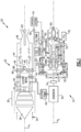
Figure 1 is a schematic view of an example combined cycle aircraft propulsion system embodiment. -
Figure 2A is a schematic view of the power generation section of the combined cycle engine ofFigure 1 . -
Figure 2B is a schematic view of an example electric motor driven fuel and oxidizer pump embodiment. -
Figure 3 is a schematic view of the combined cycle engine ofFigure 1 shown in a first engine operating configuration. -
Figure 4 is a schematic view of the combined cycle engine ofFigure 1 shown in a second engine operating configuration. -
Figure 1 schematically illustrates anexample propulsion system 20 for use as a single stage or two stage to orbit aircraft or vehicle. Theexample propulsion system 20 useselectric power 64 generated by apower generation system 24 to drive an electric motor poweredfan section 26 of a combined cycle engine 22. Afan discharge flow 36 from the fan is communicated into anaugmentor 44, mixed withfuel 46 and ignited to generate apropulsive gas flow 60 when operating in a first engine operating configuration. In a second engine operating configuration, thefan section 26 is turned off and fan discharge air replaced with aliquid oxygen flow 48 mixed with thefuel 46 to generate thepropulsive flow 60. Accordingly, the combined cycle engine 22 transitions from utilizing thefan section 26 to produce the propulsive thrust to operation as a rocket engine. - The
propulsion system 20 includes the combined cycle engine 22 disposed along an engine axis A1 and thepower generation system 24 that is disposed along a secondary axis A2. The example combined cycle engine 22 includes a liquidhydrogen fuel system 50 that provides a liquidhydrogen fuel flow 46 toinjectors 96 disposed within theaugmentor 44. Apump 52 provides the flow ofliquid hydrogen fuel 46 toinjectors 96. Aliquid oxygen system 54 including anoxygen pump 56 provides liquid oxygen tooxygen injectors 98 for operation in the second engine operating configuration. - The
example fan section 26 includes a multi-stage fan 32 that compresses inletairflow 34 through a translatinginlet 38. The multi-stage fan 32 is driven through ashaft 30 coupled to anelectric motor 28.Fan discharge air 36 is communicated through abypass duct 40 into theaugmentor 44.Duct blockers 42 are provided to controlfan discharge airflow 36 communication into theaugmentor 44. -
Electric power 64 to drive theelectric motor 28 along with other electric accessory items, pumps and/or actuators is provided by the electricpower generation system 24. The electricpower generation system 24 is located along a second axis A2 that is set apart from the first axis A1. Although the examplepower generation system 24 is shown arranged proximate to the combined cycle engine 22, thepower generation system 24 may be mounted separate from the combined cycle engine 22 within the aircraft, vehicle fuselage or other structures. - The example electric
power generation system 24 is a hydrolox powerplant that burns a mixture of liquid hydrogen (LH2) and liquid oxygen (LOX). Combusting the hydrogen with the oxygen within the hydrolox powerplant eliminates nitrous oxide emissions and enables generation of electric power independent of oxygen content in an operational environment. - The electric
power generation system 24 generates anexhaust gas flow 76 that is expanded through afree turbine section 66 to drive ashaft 72. Theshaft 72 drives thegenerator 62 through agearbox 74. The example electricpower generation system 24 utilizes liquid hydrogen (LH2) fuel and liquid oxygen (LOX) oxidizer that are mixed in acombustor 92 to generate theexhaust gas flow 76 that expands through thefree turbine section 66 and out through anozzle 94. - The
fuel system 50 for the combined cycle engine 22 may drawfuel flow 46 from aliquid hydrogen tank 78 that also supplies fuel flow to thepower generation system 24. Although hydrogen is disclosed by way of example, other fuels could be utilized and are within the contemplation of this invention. Theoxygen system 54 of the combined cycle engine 22 may draw theoxygen flow 48 from aliquid oxygen tank 82 that also supplies thepower generation system 24. Theexample oxygen system 54 may provide oxygen in a liquid form, or may provide an oxygen enhanced flow from separating oxygen from an inlet airflow. Other oxidizers may also be used within the contemplation and scope of this invention. - Referring to
Figure 2A with continued reference toFigure 1 , thepower generation system 24 uses a hot gas flow generated by combustion of the fuel and oxidizer to drive a fuel turbopump 134 and an oxidizer turbopump 136. The fuel turbopump 134 includes a turbine 106 driving afuel pump 84. The oxidizer turbopump 136 includes a turbine 108 that drives anoxidizer pump 85. The fuel turbopump 134 and the oxidizer turbopump 136 are driven by a gas flow generated bypre-burners fuel pump 84 intopassage 132 in communication with the pre-burner 90. Liquid oxygen is discharged intopassage 130 and communicated to the pre-burner 86. The discharge flows are mixed to provide a fuel and oxygen mixture needed in each of the pre-burners 86, 90. - Referring to
Figure 2B , although the turbopumps are disclosed by way of example, thefuel pump 84 andoxidizer pump 85 may be driven by a corresponding electric motor indicated schematically at 80A and 80B. - Referring back to
Figure 2A , the pre-burners 86, 90 communicate exhaust gases into a manifold 110 that is in communication with thecombustor 92. Anoxygen flow 128 and ahydrogen flow 126 are also communicated to thecombustor 92 through thehot gas manifold 110 and burnt.Injectors 120 at the end of the manifold 110 inject additional hydrogen fuel into the oxygen rich combusted gases generated in thecombustor 92. Theinjectors 120 may be spray bars that inject liquid hydrogen into the gas stream from thecombustor 92 to increase the temperature of theexhaust gas flow 76. - The
exhaust gas flow 76 expands through thefree turbine section 66 and then exhausted through anozzle 94 to an ambient environment. Theexhaust gas flow 76 expands through the multi-stagefree turbine section 66 to generate a mechanical power output utilized to drive thegenerator 62. The examplefree turbine section 66 includes afirst turbine 68 and asecond turbine 70 that are both coupled to drive theshaft 72. Although the examplefree turbine section 66 is shown by example as including first andsecond turbines - The
free turbine section 66 may be cooled by a flow of a gaseous oxygen flow through turbine cooling passages exiting from the oxygen coolingflow heat exchanger 122. This heat exchange obtains liquid oxygen from 130 and then heats it with a bleed of hot gas frommanifold 110. Excess cooling oxygen flow may be exhausted through thenozzle 94. Thenozzle 94 may be fixed or variable to enhance engine operation. Theexhaust gas flow 76 exhausted from the electricpower generation system 24 supplements the primarypropulsive flow 60 generated in the combined cycle engine 22. - An alternate configuration of the example power generation system could delete the
combustor 92, turbine cooling features, and the oxygen turbine coolingflow heat exchanger 122. The alternate configuration would be uncooled and may also change the pre-burner gas flow to be hydrogen rich to address application specific operation. - A
recuperator 124 may be provided to pre-heat the liquid hydrogen fuel flow with heat from theexhaust gas flow 76. The amount of hydrogen fuel can be controlled by a valve. The preheated liquid hydrogen fuel flow may be communicated to theinjectors 120 aft of thecombustor 92. Theoxygen tank 82 may includetank pressurization heater 114. Theliquid hydrogen tank 78 may also include atank pressurization heater 112. Liquid hydrogen is communicated throughfuel line 116 to the turbopump 134. Liquid oxygen is provided through theoxygen line 118. - To control pressure levels, the
oxygen tank 82 has a valve to vent to the atmosphere. A similar mechanism on thehydrogen tank 78 vents back into the engine flow path upstream of thenozzle 58. - Although the
power generation system 24 is shown by way of example as providing the electric power to drive theelectric motor 28 of the combined cycle engine 22, other electric generation or supply systems may also be utilized and are within the contemplation of this invention. - Referring to
Figure 3 with continued reference toFigure 1 , the combined cycle engine 22 is shown in a first engine operating configuration 100. In the first engine operating configuration, the translatinginlet 38 is in an open position whereinlet airflow 34 is communicated to thefan section 26. Theinlet airflow 34 is pressurized through the multiple stages 32 of thefan section 26 into thebypass duct 40. Theduct blocker 42 is open to enable thefan discharge flow 36 into theaugmentor 44. Although the translatinginlet 38 is shown and described by way of example, other inlet control and shutoff devices may also be utilized and are within the scope and contemplation of this invention. - The liquid
hydrogen fuel system 50 provides thefuel flow 46 that mixes with the fanair discharge flow 36 and burned to generate thepropulsive gas flow 60. Theoxygen system 54 is in an off condition as oxygen from the fan air discharge flow is utilized to support combustion and generate thepropulsive gas flow 60. Operation in the first engine operating configuration 100 requires an inlet airflow with sufficient oxygen content to support combustion. Moreover, with increasing speeds, the ability of thefan section 26 to generate the required fan discharge flows needed decreases. Accordingly, as speeds increase, the combined cycle engine 22 is transitioned into operation as a rocket engine. - Referring to
Figure 4 , the example combined cycle engine 22 is shown in a secondengine operating configuration 102. In the secondengine operating configuration 102, the translatinginlet 38 is in an off position that prevents inlet airflow into thefan section 26. Thefan section 26 is turned off and theduct blocker 42 is closed such that no fan discharge air is communicated to theaugmentor 44. Theoxygen system 54 is turned on to provides anoxygen flow 48 that is mixed with thefuel flow 46 and burned to generate thepropulsive flow 60. Theexample oxygen flow 48 may be liquid oxygen or an oxygen enriched flow that provides the oxidant required for combustion. Thepropulsive flow 60 is exhausted through anozzle 58 to provide the desired thrust. Theexample nozzle 58 is a converging diverging nozzle. Other fixed and variable nozzle configurations could be utilized and are within the contemplation of this invention. - Referring to
Figures 3 and 4 , an example operational embodiment of thepropulsion system 20 is initiated with the combined cycle engine 22 arranged according to the first engine operating configuration shown inFigure 3 . In the first engine operating configuration 100, the translatinginlet 38 is in an open position to allow inlet airflow into thefan section 26. Theduct blocker 42 is open to allow thefan discharge airflow 36 into theaugmentor 44.Electric power 64 from thepower generation system 24 is provided to drive thefan section 26. Thefan section 26 drivesfan discharge airflow 36 into theaugmentor 44 where it is mixed withliquid hydrogen fuel 46 and burned to generate thepropulsive flow 60. The flow of liquid oxygen is turned off as thefan discharge flow 36 provides sufficient oxygen for combustion. The combined cycle engine 22 operates in the first engine operating configuration 100 through takeoff and climb to altitude as the aircraft accelerates to higher supersonic speeds. - As speeds increase, the translating
inlet 38 may be adjusted to condition and control theinlet airflow 34. Power to thefan section 26 is reduced as the translatinginlet 38 and flow provides sufficient compression of inlet airflow similar to ram jet operation. At a desired speed and/or defined operating condition, the translatinginlet 38 closes inlet airflow and thefan section 26 is shut off. - Once
inlet airflow 34 is shut off, the combined cycle engine 22 transitions to operation in the secondengine operating configuration 102 as shown inFigure 4 . Theinlet airflow 34 is turned off and theduct blocker 42 is closed such that no outside airflow is provided to theaugmentor 44. Theliquid oxygen flow 48 is turned on and mixed with theliquid fuel flow 46 generate thepropulsive flow 60. In the secondengine operating configuration 102, the combined cycle engine 22 is operating as a rocket engine to increase thrust and speeds. The combined cycle engine 22 may operate at a maximum thrust until transitioned back to the first engine operating configuration 100. - Alternatively, the combined cycle engine 22 may be configured with multiple stages to further increase thrust capacity. The combined cycle engine 22 may be ejected as a first stage and the aircraft transitioned to a subsequent stage configured to provide an increase in thrust for further operation of the aircraft or vehicle.
- Accordingly, the example propulsion system utilizes an electrically driven fan to smooth transition of the combined cycle engine from lower Mach number jet engine thrust levels to higher Mach number rocket engine thrust levels.
- Although an example embodiment has been disclosed, a worker of ordinary skill in this art would recognize that certain modifications would come within the scope of this invention. For that reason, the following claims should be studied to determine the scope and content of this invention.
Claims (15)
- A propulsion system (20) for an air vehicle, the propulsion system (20) comprising:a fan system (26) including a fan (32) coupled to a fan drive electric motor (28) for generating a fan discharge airflow (36);an augmentor (44) where fuel (46) is mixed with a portion of the fan discharge airflow (36) to generate a propulsive flow (60) in a first operating configuration (100);a bypass duct (40) for directing the fan discharge airflow (36) into the augmentor (44);a duct blocker (42) for selectively closing the bypass duct (40) to the fan discharge airflow (36);a liquid oxygen system (54) configured to inject liquid oxygen (48) into the augmentor (44) to mix with the fuel (46) when the fan discharge airflow (36) is closed by the duct blocker (42), wherein the mixture of fuel flow (46) and liquid oxygen (48) generates the propulsive flow (60) in a second operating configuration (102); andan electric power generation system (24) coupled to drive the fan drive electric motor (28).
- The propulsion system (20) as recited in claim 1, further including a translating inlet (38) movable between an open position allowing inlet airflow (34) to the fan system (26) and a closed position shutting inlet airflow (34) to the fan system (26).
- The propulsion system (20) as recited in claim 2, wherein in the first operating configuration, the fan (32) generates a fan discharge flow (36) through the augmenter and in the second operating configuration, the translating inlet (38) is closed and the propulsive flow (60) is generated by combustion of a mixture of fuel (46) and liquid oxygen (48) in the augmentor (44).
- The propulsion system (20) as recited in any preceding claim, wherein the electric power generation system (24) comprises a generator (62) coupled to a free turbine (68, 70) driven by an exhaust gas flow (76).
- The propulsion system (20) as recited in claim 4, wherein the exhaust gas flow (76) is generated by a mixture of fuel and liquid oxygen in a combustor (92) that expands through the free turbine (68, 70) and is exhausted through a nozzle (94).
- The propulsion system (20) as recited in claim 5, further including a fuel pump (84) for pressurizing a fuel flow to the combustor (92) and an oxidizer pump (85) for pressurizing a liquid oxygen flow to the combustor (92).
- The propulsion system (20) as recited in claim 6, wherein:the fuel pump (84) comprises a fuel turbopump (134) and the oxidizer pump (85) comprises an oxidizer turbopump (136), and both the fuel turbopump (134) and the oxidizer turbopump (136) are configured to be driven by a hot gas flow generated by combustion of a mixture of fuel and oxidizer; and/orthe fuel pump (84) is driven by a first electric motor (80A) and the oxidizer pump (85) is driven by a second electric motor (80B).
- The propulsion system (20) as recited in any of claims 4 to 7, further including:a gearbox (74) driven by the free turbine (68, 70); andan output coupled to drive the generator (62).
- The propulsion system (20) as recited in any preceding claim, wherein the propulsive flow (60) is expelled through a converging diverging nozzle (58).
- An aircraft propulsion system (20) comprising:a fan system (26) including a fan (32) coupled to a fan drive electric motor (28) configured to generate a fan discharge flow (36);a translating inlet (38) movable between an open position allowing inlet airflow (34) to the fan system (26) and a closed position closing off inlet airflow (34) to the fan system (26);a fuel system (50) providing a flow of fuel (46);an augmentor (44) configured to generate a propulsive gas flow (60) from a mixture of fuel (46) and the fan discharge airflow (36) in a first engine operating configuration (100);a duct blocker (42) movable between an open and a closed position for controlling the fan discharge flow (36) to the augmentor (44); anda liquid oxygen system (54) configured to provide oxygen (48) to the augmentor (44) to mix with the fuel (46) and generate the propulsive gas flow (60) in a second engine operating configuration (102), wherein in the second engine operating configuration (102), the duct blocker (42) is in a closed position such that no fan discharge flow (36) is communicated to the augmentor (44); andan electric power generation system (24) having a generator (62) coupled to a free turbine section (68, 70), wherein the free turbine section (68, 70) is driven by an exhaust gas flow (76) generated by a mixture of fuel and liquid oxygen.
- The aircraft propulsion system (20) as recited in claim 10, wherein the electricity generating system (24) includes:a combustor (92) where the fuel and liquid oxygen are mixed and ignited to generate the exhaust gas flow (76);a fuel pump (84) for pressurizing a fuel flow (46) communicated to the combustor (92); andan oxidizer pump (85) for pressurizing a liquid oxygen flow to the combustor (92), wherein, optionally:
the fuel pump (84) comprises a fuel turbopump (134) and the oxidizer pump (85) comprises an oxidizer turbopump (136), and each of the fuel turbopump (134) and the oxidizer turbopump (136) are driven by a hot gas flow. - The propulsion system (20) or aircraft propulsion system (20) as recited in any preceding claim, wherein the fan (32) of the fan system (26) comprises a multi-stage fan.
- A method of operating an aircraft propulsion system (20) comprising:generating electric power (64) with a free turbine (68, 70) driven generator (62);driving a fan (32) with an electric motor (28) to generate a fan discharge flow (36), wherein the electric motor (28) is driven by the generated electric power (64) from the generator (62);mixing the fan discharge airflow (36) with fuel (46) in an augmentor (44) to generate a propulsive gas flow (60) exhausted through a nozzle (58) in a first engine operating configuration (100); andclosing off the fan discharge airflow (36) to the augmentor (44) and communicating an oxygen flow (48) to the augmentor (44) for mixing with the fuel (46) to generate the propulsive gas flow (60) that is exhausted through the nozzle (58) in a second engine operating configuration (102).
- The method as recited in claim 13, wherein generating electric power (64) comprises generating an exhaust gas flow (76) from a flow of oxygen and fuel ignited in a combustor (92) for driving the free turbine (68, 70) in an electricity generation system separate from the fan (32).
- The method as recited in claim 13 or 14, further comprising:controlling inlet flow (34) to the fan (32) with a translating inlet (38), wherein the translating inlet (38) is open in the first engine operating configuration (100) and closed in the second engine operating configuration (102); and/oroperating in the first engine operating configuration (100) for a first set of flight conditions and operating in the second engine operating configuration (102) for a second set of flight conditions and transitioning between the first engine operating configuration (100) and the second engine operating configuration (102) by closing fan discharge airflow (36) to the augmentor (44) and communicating a liquid oxygen flow (48) to the augmentor (44).
Applications Claiming Priority (1)
| Application Number | Priority Date | Filing Date | Title |
|---|---|---|---|
| US18/342,016 US12259134B2 (en) | 2023-06-27 | 2023-06-27 | Hydrogen liquid oxygen combined cycle engine |
Publications (1)
| Publication Number | Publication Date |
|---|---|
| EP4484724A1 true EP4484724A1 (en) | 2025-01-01 |
Family
ID=91738044
Family Applications (1)
| Application Number | Title | Priority Date | Filing Date |
|---|---|---|---|
| EP24184953.8A Pending EP4484724A1 (en) | 2023-06-27 | 2024-06-27 | Hydrogen liquid oxygen combined cycle engine |
Country Status (2)
| Country | Link |
|---|---|
| US (2) | US12259134B2 (en) |
| EP (1) | EP4484724A1 (en) |
Citations (3)
| Publication number | Priority date | Publication date | Assignee | Title |
|---|---|---|---|---|
| US20030029162A1 (en) * | 2000-01-12 | 2003-02-13 | Baker Von David | Propulsion module |
| US20060107648A1 (en) * | 2004-02-19 | 2006-05-25 | Aerojet-General Corporation, A Corporation Of The State Of Ohio | Integrated air inlet system for multi-propulsion aircraft engines |
| US20200284224A1 (en) * | 2019-01-14 | 2020-09-10 | HyperSpace Propulsion, Inc. | Hypersonic superconducting combustion ram accelerated magnetohydrodynamic-drive |
Family Cites Families (12)
| Publication number | Priority date | Publication date | Assignee | Title |
|---|---|---|---|---|
| US2716329A (en) * | 1952-08-01 | 1955-08-30 | David R Lunger | Jet engine |
| GB805418A (en) * | 1955-10-05 | 1958-12-03 | Power Jets Res & Dev Ltd | Jet propulsion plant |
| US3237400A (en) * | 1957-04-05 | 1966-03-01 | United Aircraft Corp | Turborocket engine |
| DE3617757C1 (en) * | 1986-05-30 | 1987-07-02 | Erno Raumfahrttechnik Gmbh, 2800 Bremen, De | |
| FR2656382B1 (en) * | 1989-12-21 | 1994-07-08 | Europ Propulsion | HIGH ADAPTABILITY COMBINED PROPULSION ENGINE FOR AIRCRAFT OR SPACE AIRCRAFT. |
| US6058846A (en) * | 1998-06-03 | 2000-05-09 | Lockhead Martin Corporation | Rocket and ramjet powered hypersonic stealth missile having alterable radar cross section |
| WO2004072451A1 (en) | 2003-02-12 | 2004-08-26 | Ishikawajima-Harima Heavy Industries Co., Ltd. | Pulse detonation engine system for driving turbine |
| US7178339B2 (en) | 2004-04-07 | 2007-02-20 | Lockheed Martin Corporation | Closed-loop cooling system for a hydrogen/oxygen based combustor |
| US20090113873A1 (en) * | 2005-03-16 | 2009-05-07 | Erik Henry Tweeton | Continously air breathing assisted jet engine linear aerospkie rocket |
| US20100083632A1 (en) * | 2008-10-08 | 2010-04-08 | Searete Llc, A Limited Liability Corporation Of The State Of Delaware | Hybrid propulsive engine including at least one independently rotatable compressor rotor |
| FR3003514B1 (en) * | 2013-03-25 | 2016-11-18 | Eurocopter France | AIRCRAFT WITH REVOLVING SAIL WITH HYBRID MOTORIZATION. |
| US20200325822A1 (en) | 2019-04-14 | 2020-10-15 | Hamilton Sundstrand Corporation | Power modules with blow down fuel and propellant delivery systems |
-
2023
- 2023-06-27 US US18/342,016 patent/US12259134B2/en active Active
-
2024
- 2024-06-27 EP EP24184953.8A patent/EP4484724A1/en active Pending
-
2025
- 2025-03-11 US US19/076,381 patent/US20250271142A1/en active Pending
Patent Citations (3)
| Publication number | Priority date | Publication date | Assignee | Title |
|---|---|---|---|---|
| US20030029162A1 (en) * | 2000-01-12 | 2003-02-13 | Baker Von David | Propulsion module |
| US20060107648A1 (en) * | 2004-02-19 | 2006-05-25 | Aerojet-General Corporation, A Corporation Of The State Of Ohio | Integrated air inlet system for multi-propulsion aircraft engines |
| US20200284224A1 (en) * | 2019-01-14 | 2020-09-10 | HyperSpace Propulsion, Inc. | Hypersonic superconducting combustion ram accelerated magnetohydrodynamic-drive |
Also Published As
| Publication number | Publication date |
|---|---|
| US12259134B2 (en) | 2025-03-25 |
| US20250003591A1 (en) | 2025-01-02 |
| US20250271142A1 (en) | 2025-08-28 |
Similar Documents
| Publication | Publication Date | Title |
|---|---|---|
| US20240053017A1 (en) | Micro-turbine gas generator and propulsive system | |
| US6966174B2 (en) | Integrated bypass turbojet engines for air craft and other vehicles | |
| US5119626A (en) | Combined turborocket and ramjet propulsion unit | |
| JP4705727B2 (en) | Combined cycle pulse detonation turbine engine | |
| JP5325367B2 (en) | Method and apparatus for operating a gas turbine engine | |
| US10012177B2 (en) | Engine comprising a rocket combustion chamber and a heat exchanger | |
| US20030192303A1 (en) | Integrated bypass turbojet engines for aircraft and other vehicles | |
| US20080283677A1 (en) | Single-stage hypersonic vehicle featuring advanced swirl combustion | |
| EP1992788B1 (en) | Aircraft combination engines plural airflow conveyances system | |
| US20080128547A1 (en) | Two-stage hypersonic vehicle featuring advanced swirl combustion | |
| EP4227510A1 (en) | Liquid hydrogen-liquid oxygen fueled powerplant | |
| US7788899B2 (en) | Fixed nozzle thrust augmentation system | |
| EP4484724A1 (en) | Hydrogen liquid oxygen combined cycle engine | |
| US11846251B1 (en) | Liquid rocket engine booster engine with combustion gas fuel source | |
| US20240229745A9 (en) | Duplex Turbine Guide Vane Assembly | |
| US11879415B2 (en) | Jet engine for aircraft | |
| US11041463B1 (en) | Turbine engine structure with oxidizer enhanced mode | |
| GB2563113A (en) | Non-positive displacement tangential flow turbine engine | |
| WO2006001927A2 (en) | Carnot cycle jet and rocket engine configurations | |
| Haran et al. | Analysis of an After Burner in a Jet Engine | |
| HK1260229A1 (en) | Micro-turbine gas generator and propulsive system |
Legal Events
| Date | Code | Title | Description |
|---|---|---|---|
| PUAI | Public reference made under article 153(3) epc to a published international application that has entered the european phase |
Free format text: ORIGINAL CODE: 0009012 |
|
| STAA | Information on the status of an ep patent application or granted ep patent |
Free format text: STATUS: THE APPLICATION HAS BEEN PUBLISHED |
|
| AK | Designated contracting states |
Kind code of ref document: A1 Designated state(s): AL AT BE BG CH CY CZ DE DK EE ES FI FR GB GR HR HU IE IS IT LI LT LU LV MC ME MK MT NL NO PL PT RO RS SE SI SK SM TR |
|
| STAA | Information on the status of an ep patent application or granted ep patent |
Free format text: STATUS: REQUEST FOR EXAMINATION WAS MADE |
|
| 17P | Request for examination filed |
Effective date: 20250701 |