EP4484717A1 - Method for mapping contrail formation to engine performance characteristics - Google Patents
Method for mapping contrail formation to engine performance characteristics Download PDFInfo
- Publication number
- EP4484717A1 EP4484717A1 EP24183561.0A EP24183561A EP4484717A1 EP 4484717 A1 EP4484717 A1 EP 4484717A1 EP 24183561 A EP24183561 A EP 24183561A EP 4484717 A1 EP4484717 A1 EP 4484717A1
- Authority
- EP
- European Patent Office
- Prior art keywords
- determining
- engine
- temperature
- contrail
- computer
- Prior art date
- Legal status (The legal status is an assumption and is not a legal conclusion. Google has not performed a legal analysis and makes no representation as to the accuracy of the status listed.)
- Pending
Links
Images




Classifications
-
- F—MECHANICAL ENGINEERING; LIGHTING; HEATING; WEAPONS; BLASTING
- F01—MACHINES OR ENGINES IN GENERAL; ENGINE PLANTS IN GENERAL; STEAM ENGINES
- F01D—NON-POSITIVE DISPLACEMENT MACHINES OR ENGINES, e.g. STEAM TURBINES
- F01D25/00—Component parts, details, or accessories, not provided for in, or of interest apart from, other groups
-
- F—MECHANICAL ENGINEERING; LIGHTING; HEATING; WEAPONS; BLASTING
- F02—COMBUSTION ENGINES; HOT-GAS OR COMBUSTION-PRODUCT ENGINE PLANTS
- F02C—GAS-TURBINE PLANTS; AIR INTAKES FOR JET-PROPULSION PLANTS; CONTROLLING FUEL SUPPLY IN AIR-BREATHING JET-PROPULSION PLANTS
- F02C3/00—Gas-turbine plants characterised by the use of combustion products as the working fluid
- F02C3/20—Gas-turbine plants characterised by the use of combustion products as the working fluid using a special fuel, oxidant, or dilution fluid to generate the combustion products
- F02C3/30—Adding water, steam or other fluids for influencing combustion, e.g. to obtain cleaner exhaust gases
-
- B—PERFORMING OPERATIONS; TRANSPORTING
- B64—AIRCRAFT; AVIATION; COSMONAUTICS
- B64D—EQUIPMENT FOR FITTING IN OR TO AIRCRAFT; FLIGHT SUITS; PARACHUTES; ARRANGEMENT OR MOUNTING OF POWER PLANTS OR PROPULSION TRANSMISSIONS IN AIRCRAFT
- B64D33/00—Arrangement in aircraft of power plant parts or auxiliaries not otherwise provided for
- B64D33/04—Arrangement in aircraft of power plant parts or auxiliaries not otherwise provided for of exhaust outlets or jet pipes
-
- F—MECHANICAL ENGINEERING; LIGHTING; HEATING; WEAPONS; BLASTING
- F02—COMBUSTION ENGINES; HOT-GAS OR COMBUSTION-PRODUCT ENGINE PLANTS
- F02C—GAS-TURBINE PLANTS; AIR INTAKES FOR JET-PROPULSION PLANTS; CONTROLLING FUEL SUPPLY IN AIR-BREATHING JET-PROPULSION PLANTS
- F02C9/00—Controlling gas-turbine plants; Controlling fuel supply in air- breathing jet-propulsion plants
- F02C9/26—Control of fuel supply
- F02C9/28—Regulating systems responsive to plant or ambient parameters, e.g. temperature, pressure, rotor speed
-
- G—PHYSICS
- G01—MEASURING; TESTING
- G01W—METEOROLOGY
- G01W1/00—Meteorology
- G01W1/08—Adaptations of balloons, missiles, or aircraft for meteorological purposes; Radiosondes
-
- F—MECHANICAL ENGINEERING; LIGHTING; HEATING; WEAPONS; BLASTING
- F05—INDEXING SCHEMES RELATING TO ENGINES OR PUMPS IN VARIOUS SUBCLASSES OF CLASSES F01-F04
- F05D—INDEXING SCHEME FOR ASPECTS RELATING TO NON-POSITIVE-DISPLACEMENT MACHINES OR ENGINES, GAS-TURBINES OR JET-PROPULSION PLANTS
- F05D2260/00—Function
- F05D2260/82—Forecasts
- F05D2260/821—Parameter estimation or prediction
-
- F—MECHANICAL ENGINEERING; LIGHTING; HEATING; WEAPONS; BLASTING
- F05—INDEXING SCHEMES RELATING TO ENGINES OR PUMPS IN VARIOUS SUBCLASSES OF CLASSES F01-F04
- F05D—INDEXING SCHEME FOR ASPECTS RELATING TO NON-POSITIVE-DISPLACEMENT MACHINES OR ENGINES, GAS-TURBINES OR JET-PROPULSION PLANTS
- F05D2270/00—Control
- F05D2270/01—Purpose of the control system
- F05D2270/08—Purpose of the control system to produce clean exhaust gases
- F05D2270/083—Purpose of the control system to produce clean exhaust gases by monitoring combustion conditions
-
- F—MECHANICAL ENGINEERING; LIGHTING; HEATING; WEAPONS; BLASTING
- F05—INDEXING SCHEMES RELATING TO ENGINES OR PUMPS IN VARIOUS SUBCLASSES OF CLASSES F01-F04
- F05D—INDEXING SCHEME FOR ASPECTS RELATING TO NON-POSITIVE-DISPLACEMENT MACHINES OR ENGINES, GAS-TURBINES OR JET-PROPULSION PLANTS
- F05D2270/00—Control
- F05D2270/30—Control parameters, e.g. input parameters
- F05D2270/311—Air humidity
-
- Y—GENERAL TAGGING OF NEW TECHNOLOGICAL DEVELOPMENTS; GENERAL TAGGING OF CROSS-SECTIONAL TECHNOLOGIES SPANNING OVER SEVERAL SECTIONS OF THE IPC; TECHNICAL SUBJECTS COVERED BY FORMER USPC CROSS-REFERENCE ART COLLECTIONS [XRACs] AND DIGESTS
- Y02—TECHNOLOGIES OR APPLICATIONS FOR MITIGATION OR ADAPTATION AGAINST CLIMATE CHANGE
- Y02T—CLIMATE CHANGE MITIGATION TECHNOLOGIES RELATED TO TRANSPORTATION
- Y02T50/00—Aeronautics or air transport
- Y02T50/60—Efficient propulsion technologies, e.g. for aircraft
Definitions
- This present invention relates to aircraft engine performance characteristics, and more particularly, to contrail formation based on engine performance.
- Aircraft contrails are an important contributor to climate change. Contrails both trap outgoing radiation from the earth and reflect incoming radiation from the sun. On a global basis, contrails have been found to have a net warming impact, meaning that they trap more energy than they reflect, but each individual contrail is different. Contrails form when exhaust gases locally exceed the water saturation limit while mixing and cooling to ambient conditions. However, recent research has shown that only approximately 20% of flights globally produce contrails, and furthermore, that less than 10% of flights account for 80% of the global climate warming from contrails. This leads to the conclusion that a fleetwide action is not necessary and that targeted action to mitigate contrail production by worst offenders is most appropriate.
- a computer-implemented method of determining a minimum humidity required for formation and persistence of contrails produced by an engine of an aircraft includes determining engine performance model parameters of the engine at desired operating conditions with zero humidity; determining additional energy flow out of the engine; and determining an exhaust plume temperature scaling factor.
- the method further comprises determining a contrail engine efficiency parameter (noverall_ ⁇ ) based on additional energy flow out of the engine and the exhaust plume temperature scaling factor; and generating an improved Schmidt-Appleman equation (G ⁇ ) based on the contrail engine efficiency parameter (noverall_ ⁇ ).
- the method further includes determining an improved mixing line slope based on the improved Schmidt-Appleman equation (G ⁇ ); and determining the minimum humidity required for formation and persistence of contrails produced by the engine based on the improved mixing line slope.
- a computer system includes a processor having memory storing instruction, which when executed by the processor, controls the computer system to perform the computer-implemented method.
- the engine performance model parameters include a residual fuel energy in the aircraft engine.
- the residual fuel energy in the aircraft engine is determined based on the contrail engine efficiency parameter (noverall_ ⁇ ).
- a controller determines the residual fuel energy in the aircraft engine based on the contrail engine efficiency parameter (noverall_ ⁇ ).
- the exhaust plume temperature scaling factor is 0.5.
- the additional energy flow includes power extraction and bleed offtakes used by an aircraft air management system and an electrical system of the aircraft.
- a computer-implemented method to generate contrail formation and persistence maps by evaluating the minimum humidity required for formation and persistence over the engine operating envelope of a given aircraft engine comprises determining engine performance model parameters of the engine at desired operating conditions with zero humidity; determining a contrail engine efficiency parameter (noverall_ ⁇ ); determining an improved Schmidt-Appleman equation (G ⁇ ) based on the contrail engine efficiency parameter (noverall_ ⁇ ); determining an improved mixing line slope based on the contrail engine efficiency parameter (noverall_ ⁇ ) and the improved Schmidt-Appleman equation (G ⁇ ); determining a tangency temperature value at which a slope of a first saturation limit with respect to water vs temperature is the same as the improved mixing line slope; determining a first partial pressure of water value at the tangency temperature based on the improved mixing line slope; determining a second partial pressure of water value at a second saturation limit with respect to water at the tangency temperature; determining a difference ( ⁇ ) between
- a computer system includes a processor having memory storing instruction, which when executed by the processor, controls the computer system to perform the computer implemented method.
- the engine performance model parameters include a residual fuel energy in the aircraft engine.
- the residual fuel energy in the aircraft engine is determined based on the contrail engine efficiency parameter (noverall_ ⁇ ).
- a controller determines the residual fuel energy in the aircraft engine based on the contrail engine efficiency parameter (noverall_ ⁇ ).
- the exhaust plume temperature scaling factor is 0.5.
- the additional energy flow includes power extraction and bleed offtakes used by an aircraft air management system and an electrical system of the aircraft.
- determining the first partial pressure of water value is based on the improved mixing line slope starting from an ambient temperature and zero humidity.
- determining the difference ( ⁇ ) is set to zero when the difference ( ⁇ ) is negative.
- the tangency temperature value is determined analytically.
- the processor computes the tangency temperature value analytically.
- the tangency temperature value is determined numerically.
- the processor computes the tangency temperature value numerically.
- a computer-implemented method of determining a minimum humidity necessary to form contrails by an engine of an aircraft comprises: determining engine performance model parameters of the engine at desired operating conditions; determining a contrail engine efficiency parameter (noverall_ ⁇ ); determining an improved Schmidt-Appleman equation (G ⁇ ) based on the contrail engine efficiency parameter (noverall_ ⁇ ); determining an improved mixing line slope based on the contrail engine efficiency parameter (noverall_ ⁇ ) and the improved Schmidt-Appleman equation (G ⁇ ); determining a tangency temperature value at which a slope of a first saturation limit with respect to water vs temperature is the same as the improved mixing line slope; determining a partial pressure of water at the first saturation limit with respect to water at the tangency temperature; determining a first temperature at the partial pressure of water based on the improved mixing line slope; determining a minimum temperature margin with respect to dew point based on the temperature at the partial pressure and the tangency temperature value;
- a computer system includes a processor having memory storing instruction, which when executed by the processor, controls the computer system to perform the computer implemented method.
- determining the temperature at the partial pressure of water includes determining the temperature at the partial pressure of water starting from the desired operating conditions.
- the contrail engine efficiency parameter (noverall_ ⁇ ) comprises: determining an exhaust plume temperature scaling factor that scales a kinetic energy of the engine by a factor 0.5; and applying the exhaust plume temperature scaling factor to the contrail engine efficiency parameter (noverall_ ⁇ ).
- the minimum temperature margin with respect to dew point is a difference between the temperature at the partial pressure and the tangency temperature.
- the tangency temperature value is determined analytically.
- the processor computes the tangency temperature value analytically.
- the tangency temperature value is determined numerically.
- the processor computes the tangency temperature value numerically.
- C p C p ⁇ P amb ⁇ ⁇ 1 1 ⁇ ⁇ overall ⁇ EI H 2 O LHV
- the Schmidt-Appleman equation approximates the change in partial pressure of water vs temperature in the plume as exhaust gases mix with ambient air and cool to ambient conditions.
- the relationship of partial pressure of water with respect to temperature in the plume is referred to as the "mixing line", or the “mixing line slope” (G[psi/°F]).
- the saturation limit of air with respect to water and ice can both be defined in terms of partial pressure of water vapor versus static temperature.
- the partial pressure of water vapor can be expressed as a molecular fraction of water in the air multiplied by the surrounding air pressure.
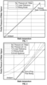
- FIG. 1 is a graph illustrating the relationship between partial pressure of water vapor versus static temperature.
- the Schmidt-Appleman equation utilizes an energy efficiency parameter ( ⁇ overall) to determine an aircraft residual fuel energy (1- ⁇ overall), or the amount of energy spent moving the aircraft.
- the traditional energy efficiency parameter ( ⁇ overall) does not take into account either: (1) additional energy that flows out of the engine such as, for example, power extraction and bleed offtakes used by the aircraft air management system and electrical systems; and (2) how the exhaust plume temperature is affected by the simultaneous kinetic energy loss to heat and cooling to ambient temperature due to dilution.
- the traditional efficiency parameter ( ⁇ overall) provides poor alignment with the results of the physics-based 1-dimensions plume model, and reduces the accuracy of mixing line slope generated according to the traditional Schmidt-Appleman equation as illustrated by the graph depicted in FIG. 2 .
- One or more non-limiting embodiments of the present disclosure provide a method for mapping contrail formation to engine performance characteristics to rapidly developing engine-specific contrail formation maps.
- the method includes determining an contrail engine efficiency parameter ( ⁇ overall_ ⁇ ), which takes into account: (1) other energy that flows out of the engine such as, for example, power extraction and bleed offtakes used by the aircraft air management system and electrical systems; and (2) how the exhaust plume temperature is affected by the simultaneous kinetic energy loss to heat and cooling to ambient temperature due to dilution.
- ⁇ overall_ ⁇ an contrail engine efficiency parameter
- an improved mixing line slope (G ⁇ [psi/°F]) can be determined using the contrail engine efficiency parameter (noverall_ ⁇ ) to develop engine-specific contrail formation maps having improved precision and accuracy compared to contrail maps generated according to the traditional Schmidt-Appleman equation.
- the maps include minimum humidity for contrail formation and persistence that can be combined with engine operating conditions, atmospheric data, and contrail climate impact models to identify conditions of targeted contrail avoidance.
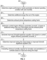
- FIG. 3 a method of determining an improved relationship of partial pressure of water with respect to temperature in an engine plume of an aircraft is illustrated according to a non-limiting embodiment of the present disclosure.
- the improved relationship can be utilized to determine a minimum humidity required for formation and persistence of contrails produced by an aircraft engine.
- the method begins at operation 300, and engine performance model parameters of a given aircraft engine at desired (i.e., target) operating conditions with zero humidity are determined at operation 302.
- the engine performance model parameters include, but are not limited to, mass flow rate of air per fuel in the plume (waif), lower heating value of fuel (LHV), local heat capacity of plume (C p ), and residual fuel energy in the aircraft engine (1- ⁇ overall_ ⁇ ).
- the residual fuel energy in the aircraft engine (1- ⁇ overall_ ⁇ ) is determined using an contrail engine efficiency parameter ( ⁇ overall_ ⁇ ), which is described in greater detail below.
- the desired operating conditions include, but are not limited to, partial pressure of water in plume per exhaust (ep/E), total temperature in plume per exhaust (Tp/E), emissions index of water (EI H2O ), ambient pressure (P amb ), and water-to-air molar mass ratio ( ⁇ ).
- the energy flow parameter indicative of additional energy in the jet exhaust is determined, which takes into account the mass flow rate of the jet exhaust at engine nozzle ( ⁇ j ), enthalpy of the jet exhaust at engine nozzle (h j ), enthalpy of the engine inlet flow (hi), and axial and tangential velocity of the plume relative to the engine (V Aj / V Tj ), and forward flight velocity of the aircraft (V).
- the additional energy flow parameter for energy in the jet exhaust can be determined according to the following equation, which includes parameters for the mass flow rate of bleed air ( ⁇ b), the enthalpy of bleed air (hb), the mass flow rate of fuel ( ⁇ f), the lower hearing value of the fuel (LHV), and power extraction from the engine (Q HPX ) :
- Energy IN Energy OUT m ⁇ j + m ⁇ b ⁇ h i + m ⁇ f ⁇
- LHV m ⁇ j ⁇ h j + 1 2 V Aj ⁇ V 2 + V Tj 2 + Q ⁇ HPX + m ⁇ b ⁇ h b + m ⁇ j ⁇ V Aj ⁇ V ⁇ V
- an exhaust plume temperature scaling factor (k) is set.
- the exhaust plume temperature scaling factor (k) scales the kinetic energy (1/2((V Aj -V) 2 + (V TJ ) 2 )) of the aircraft engine by a factor 0.5, which takes into account how the exhaust plume temperature is affected by the simultaneous kinetic energy loss to heat and cooling to ambient temperature due to dilution.
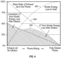
- a diagram illustrates how the scaling factor scales the aircraft engine on a normalized scale.
- no kinetic energy loss has occurred and the plume is undiluted.
- temperature and velocity are linearly reduced with the mass ratio of the jet to overall plume (orange curve 400).
- Kinetic energy loss to heat occurs with the square of velocity reduction; heat is gained as kinetic energy is lost (blue curve 402).
- the resulting increase in plume temperature is mitigated by plume cooling to ambient temperature due to dilution.
- the product of kinetic energy loss to heat with the mass ratio of exhaust jet in the plume gives the temperature change from kinetic energy after dilution (gray curve 404).
- the curvature shown in the mixing line from Figure 1 is partly driven by this effect.
- the area under the gray curve is proportional to the mixing line curvature away from the linear reference. This in turn dictates the local slope at the bottom of the mixing line that is critical for determining contrail formation.
- a linearized model with the same area under the curve as the temperature change from kinetic energy after dilution there employs scaling factor (e.g., k 0.5) to generate a scaled kinetic energy term expressed as: k * 1 / 2 V Aj ⁇ V 2 + V TJ 2 ; 0.5 * 1 / 2 V Aj ⁇ V 2 + V TJ 2 ; and therefore, ((1/4((V Aj -V) 2 + (V TJ ) 2 )))))
- an contrail engine efficiency parameter (noverall_ ⁇ ) is determined based, at least in part, on the additional energy flow out of the engine and the exhaust plume temperature scaling factor (k) at operation 308.
- an aircraft engine residual fuel energy can be determined using the contrail engine efficiency parameter (noverall_ ⁇ ) as: (1 - noverall_ ⁇ ).
- an improved Schmidt-Appleman equation (G ⁇ [psi/°F]) is generated based, at least in part, on the contrail engine efficiency parameter (noverall_ ⁇ ).
- the engine performance model parameters, the operating conditions, and the additional energy flow parameters are input to the improved Schmidt-Appleman equation (G ⁇ [psi/°F]) to determine an more accurate mixing line slope at operation 312. Accordingly, an improved alignment over broad engine operating conditions between the improved mixing line slope and a physics-based 1-dimensional plume model can be achieved.
- the minimum humidity required for formation and persistence of contrails generated by the engine is evaluated based on the more accurate mixing line slope, and the method ends at operation 316.
- the improved mixing line slope generated by the improved Schmidt-Appleman equation can be used to generate contrail formation and persistence maps by evaluating the minimum humidity required for formation and persistence over the engine operating envelope of a given aircraft engine.
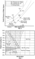
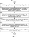
- FIGS. 5A-5B in combination with FIG. 6 a method of determining a minimum humidity necessary to form contrails is illustrated according to a non-limiting embodiment. The method begins at operation 500, and at operation 502 an engine performance model of a given engine is evaluated at desired operating condition, but with zero humidity.
- the operating conditions include, but are not limited to, altitude, ambient temperature, Mach number, and power setting.
- an improved Schmidt-Appleman mixing line slope is determined based on contrail engine efficiency parameter (noverall_ ⁇ ) and improved Schmidt-Appleman equation (G ⁇ ).
- contrail engine efficiency parameter node_ ⁇
- G ⁇ improved Schmidt-Appleman equation
- a tangency temperature value is determined.
- the tangency temperature value is the temperature at which the slope of the saturation limit with respect to water versus temperature is the same as the improved Schmidt-Appleman mixing line slope (i.e., determined at operation 504).
- the tangency temperature value can be generated analytically, and other non-limiting embodiments the tangency temperature value can be generated numerically.
- the partial pressure of water at the tangency temperature (i.e., determined at operation 506) on the mixing line is evaluated using the improved Schmidt-Appleman mixing line slope (i.e., determined in step 504) starting from the ambient temperature and zero humidity.
- the saturation limit with respect to water at the tangency temperature value is determined.
- a difference ( ⁇ ) between partial pressure of water at the saturation limit (i.e., determined at operation 510) and the partial pressure of water at the tangency temperature value (i.e., determined at operation 508) is determined.
- the difference ( ⁇ ) is set to zero if the difference is a negative value.
- the saturation limit with respect to water at the ambient temperature is determined. Accordingly, a minimum relative humidity for a contrail to form is determined at operation 516 as a ratio of the ⁇ (i.e., determined at operation 512) to the saturation limit with respect to the water (i.e., determined at operation 514).
- a saturation limit with respect to ice at ambient temperature is determined.
- a minimum relative humidity for a contrail to persist is determined at operation 520 as a ratio of the saturation limit with respect to ice (i.e., determined at operation 518) to the saturation limit with respect to water (i.e., determined at operation 514).
- the minimum relative humidity for a contrail to form and persist is determined as a the greater of the minimum relative humidity for a contrail to form (i.e., determined at operation 516) and the minimum relative humidity for a contrail to persist (i.e., determined at operation 520), and the method ends at operation 524. Accordingly, the method illustrated in FIGS 5A and 5B generates maps shown in FIG. 7 indicating the formation and persistence humidity thresholds versus altitude across the envelope of the aircraft engine.
- the method illustrated in FIGS. 5A and 5B can also be adapted to compute a map of minimum temperature margin to the dew point over the engine operating envelope.
- FIG. 8 in combination of FIG. 9 depict a method of determining a minimum temperature necessary to form contrails by a given aircraft engine at a given humidity according to a non-limiting embodiment.
- the method begins at operation 800, and an engine performance model at desired operating condition is determined at operation 802.
- the operating conditions include, but are not limited to, altitude, ambient temperature, Mach number, humidity, and power setting.
- an improved Schmidt-Appleman mixing line slope is determined based on contrail engine efficiency parameter (noverall_ ⁇ ) and improved Schmidt-Appleman equation (G ⁇ ).
- the heat capacity of air is defined for ambient temperature and humidity, and the water emissions index and LHV of the fuel is consistent with the engine performance model.
- a tangency temperature value is determined.
- the tangency temperature value is indicative of a temperature at which the slope of the saturation limit with respect to water versus temperature is the same as the improved Schmidt-Appleman mixing line slope (i.e. determined at operation 804).
- the tangency temperature value e.g., temperature slope
- the tangency temperature value can be generated analytically, and other non-limiting embodiments the tangency temperature value can be generated numerically.
- the partial pressure of water at the saturation limit with respect to water at the tangency temperature value (i.e., determined at operation 806) is determined.
- the temperature on the mixing line at this partial pressure of water e.g., determined at operation 808 is determined.
- the temperature on the mixing line at the partial pressure of water is determined using the improved Schmidt-Appleman mixing line slope (i.e., determined at operation 804) starting from the desired operating conditions (i.e., determined at operation 802).
- the minimum temperature margin to dew point is determined as a difference between the temperature on the mixing line (i.e., determined at operation 810) minus tangency temperature value (i.e., determined at operation 806), and the method ends at operation 814.
- dew point is the temperature the air needs to be cooled to (e.g., with respect to pressure) in order to achieve a relative humidity (RH) of 100%. Accordingly, the method illustrated in FIG. 8 can generate maps of the minimum temperature margin to dew point versus altitude over the engine operating envelope of the aircraft engine as shown, for example, in FIG. 10 .
- FIG. 11 a block diagram of an example computer system 1200 configured to execute the example machine readable instructions for generating mapping contrail formation to engine performance characteristics to rapidly developing engine-specific contrail formation maps according to a non-limiting embodiment of the present disclosure.
- the computer 1200 can be, for example, a server, a personal computer, or any other type of computing device.
- the system 1200 of the instant example includes a processor 1210.
- the processor 1210 can be implemented by one or more microprocessors or controllers from any desired family or manufacturer.
- the processor 1210 includes a local memory 1215 and is in communication with a main memory including a read only memory 1230 and a random access memory 1220 via a bus 1240.
- the random access memory 1220 may be implemented by Synchronous Dynamic Random Access Memory (SDRAM), Dynamic Random Access Memory (DRAM), RAMBUS Dynamic Random Access Memory (RDRM) and/or any other type of random access memory device.
- SDRAM Synchronous Dynamic Random Access Memory
- DRAM Dynamic Random Access Memory
- RDRM RAMBUS Dynamic Random Access Memory
- the read only memory 1230 may be implemented by a hard drive, flash memory and/or any other desired type of memory device.
- the computer 1200 also includes an interface circuit 1250.
- the interface circuit 1250 may be implemented by any type of interface standard, such as an Ethernet interface, a universal serial bus (USB), and/or a PCI express interface, and may interface with a network 1260.
- One or more input devices 1254 are connected to the interface circuit 1250.
- the input device(s) 1254 permit a user to enter data and commands into the processor 1210.
- the input device(s) can be implemented by, for example, a keyboard, a mouse, a touchscreen, a track-pad, a trackball, and/or a voice recognition system.
- the interface 1250 may operate in conjunction with, in parallel with, or in place of, the operator interface 115.
- One or more output devices 1258 are also connected to the interface circuit 1250.
- the output devices 1258 can be implemented by, for example, display devices for associated data (e.g., a liquid crystal display, a cathode ray tube display (CRT), etc.), and/or an actuator operatively associated with a fluid-based engineering system such as gas turbine engines for aviation and power generation, HVAC&R (heating, ventilation, air-conditioning and refrigeration), fuel cells, and other, more generalized fluid processing systems for hydrocarbon extraction, materials processing, and manufacture.
- a fluid-based engineering system such as gas turbine engines for aviation and power generation, HVAC&R (heating, ventilation, air-conditioning and refrigeration), fuel cells, and other, more generalized fluid processing systems for hydrocarbon extraction, materials processing, and manufacture.
- engine data can be used directly to compute contrail maps with atmospheric data that is measured by other on-board sensors.
- the engine performance models generated by the methods described herein can be used to pre-compute contrail maps that are used with weather forecasts to pre-compute contrail formation zones to be avoided in flight planning.
- the methods described herein can generate contrail maps as part of aircraft or engine design systems and can be utilized to evaluate contrail climate impacts for designing a candidate engine to be operated under a set of pre-defined operating conditions.
Landscapes
- Engineering & Computer Science (AREA)
- Chemical & Material Sciences (AREA)
- Mechanical Engineering (AREA)
- Combustion & Propulsion (AREA)
- General Engineering & Computer Science (AREA)
- Environmental & Geological Engineering (AREA)
- Aviation & Aerospace Engineering (AREA)
- Life Sciences & Earth Sciences (AREA)
- Environmental Sciences (AREA)
- Ecology (AREA)
- Biodiversity & Conservation Biology (AREA)
- Atmospheric Sciences (AREA)
- Combined Controls Of Internal Combustion Engines (AREA)
- Control Of Vehicle Engines Or Engines For Specific Uses (AREA)
Abstract
A computer system (1200) includes a processor (1210) controls the computer system (1200) to perform a computer-implemented method of determining a minimum humidity required for formation and persistence of contrails produced by an engine of an aircraft. The computer-implemented method includes determining engine performance model parameters of the engine at desired operating conditions with zero humidity; determining additional energy flow out of the engine; and determining an exhaust plume temperature scaling factor. The method further comprises determining a contrail engine efficiency parameter (noverall_λ) based on additional energy flow out of the engine and the exhaust plume temperature scaling factor; and generating an improved Schmidt-Appleman equation based on the contrail engine efficiency parameter (noverall_λ). The method further includes determining an improved mixing line slope based on the improved Schmidt-Appleman equation; and determining the minimum humidity required for formation and persistence of contrails produced by the engine based on the improved mixing line slope.
Description
- This present invention relates to aircraft engine performance characteristics, and more particularly, to contrail formation based on engine performance.
- Aircraft contrails are an important contributor to climate change. Contrails both trap outgoing radiation from the earth and reflect incoming radiation from the sun. On a global basis, contrails have been found to have a net warming impact, meaning that they trap more energy than they reflect, but each individual contrail is different. Contrails form when exhaust gases locally exceed the water saturation limit while mixing and cooling to ambient conditions. However, recent research has shown that only approximately 20% of flights globally produce contrails, and furthermore, that less than 10% of flights account for 80% of the global climate warming from contrails. This leads to the conclusion that a fleetwide action is not necessary and that targeted action to mitigate contrail production by worst offenders is most appropriate.
- According to an aspect of the invention, a computer-implemented method of determining a minimum humidity required for formation and persistence of contrails produced by an engine of an aircraft is provided. The computer-implemented method includes determining engine performance model parameters of the engine at desired operating conditions with zero humidity; determining additional energy flow out of the engine; and determining an exhaust plume temperature scaling factor. The method further comprises determining a contrail engine efficiency parameter (noverall_λ) based on additional energy flow out of the engine and the exhaust plume temperature scaling factor; and generating an improved Schmidt-Appleman equation (Gλ) based on the contrail engine efficiency parameter (noverall_λ). The method further includes determining an improved mixing line slope based on the improved Schmidt-Appleman equation (Gλ); and determining the minimum humidity required for formation and persistence of contrails produced by the engine based on the improved mixing line slope.
- Optionally, in addition to one or more of the features described above, or as an alternative to any of the foregoing embodiments, a computer system includes a processor having memory storing instruction, which when executed by the processor, controls the computer system to perform the computer-implemented method.
- Optionally, in addition to one or more of the features described above, or as an alternative to any of the foregoing embodiments, the engine performance model parameters include a residual fuel energy in the aircraft engine.
- Optionally, in addition to one or more of the features described above, or as an alternative to any of the foregoing embodiments, the residual fuel energy in the aircraft engine is determined based on the contrail engine efficiency parameter (noverall_λ).
- Optionally, in addition to one or more of the features described above, or as an alternative to any of the foregoing embodiments, a controller (e.g., the processor) determines the residual fuel energy in the aircraft engine based on the contrail engine efficiency parameter (noverall_λ).
- Optionally, in addition to one or more of the features described above, or as an alternative to any of the foregoing embodiments, the exhaust plume temperature scaling factor is 0.5.
- Optionally, in addition to one or more of the features described above, or as an alternative to any of the foregoing embodiments, the additional energy flow includes power extraction and bleed offtakes used by an aircraft air management system and an electrical system of the aircraft.
- According to another aspect of the invention, a computer-implemented method to generate contrail formation and persistence maps by evaluating the minimum humidity required for formation and persistence over the engine operating envelope of a given aircraft engine is provided. The computer-implemented method comprises determining engine performance model parameters of the engine at desired operating conditions with zero humidity; determining a contrail engine efficiency parameter (noverall_λ); determining an improved Schmidt-Appleman equation (Gλ) based on the contrail engine efficiency parameter (noverall_λ); determining an improved mixing line slope based on the contrail engine efficiency parameter (noverall_λ) and the improved Schmidt-Appleman equation (Gλ); determining a tangency temperature value at which a slope of a first saturation limit with respect to water vs temperature is the same as the improved mixing line slope; determining a first partial pressure of water value at the tangency temperature based on the improved mixing line slope; determining a second partial pressure of water value at a second saturation limit with respect to water at the tangency temperature; determining a difference (Δ) between the second partial pressure of water and the first partial pressure of water value; determining a third partial pressure of water at a third saturation limit with respect to water at the ambient temperature; determining a minimum relative humidity for a contrail to form as a first ratio of the difference (Δ) with respect to water; determine a fourth saturation limit with respect to ice at the ambient temperature; determining a minimum relative humidity for the contrail to persist as a second ratio of the fourth saturation limit to the third saturation limit; and determining the minimum relative humidity to form and persist as the greater of the first ratio and the second ratio.
- Optionally, in addition to one or more of the features described above, or as an alternative to any of the foregoing embodiments, a computer system includes a processor having memory storing instruction, which when executed by the processor, controls the computer system to perform the computer implemented method.
- Optionally, in addition to one or more of the features described above, or as an alternative to any of the foregoing embodiments, the engine performance model parameters include a residual fuel energy in the aircraft engine.
- Optionally, in addition to one or more of the features described above, or as an alternative to any of the foregoing embodiments, the residual fuel energy in the aircraft engine is determined based on the contrail engine efficiency parameter (noverall_λ).
- Optionally, in addition to one or more of the features described above, or as an alternative to any of the foregoing embodiments, a controller (e.g., the processor) determines the residual fuel energy in the aircraft engine based on the contrail engine efficiency parameter (noverall_λ).
- Optionally, in addition to one or more of the features described above, or as an alternative to any of the foregoing embodiments, the exhaust plume temperature scaling factor is 0.5.
- Optionally, in addition to one or more of the features described above, or as an alternative to any of the foregoing embodiments, the additional energy flow includes power extraction and bleed offtakes used by an aircraft air management system and an electrical system of the aircraft.
- Optionally, in addition to one or more of the features described above, or as an alternative to any of the foregoing embodiments, determining the first partial pressure of water value is based on the improved mixing line slope starting from an ambient temperature and zero humidity.
- Optionally, in addition to one or more of the features described above, or as an alternative to any of the foregoing embodiments, determining the difference (Δ) is set to zero when the difference (Δ) is negative.
- Optionally, in addition to one or more of the features described above, or as an alternative to any of the foregoing embodiments, the tangency temperature value is determined analytically.
- Optionally, in addition to one or more of the features described above, or as an alternative to any of the foregoing embodiments, the processor computes the tangency temperature value analytically.
- Optionally, in addition to one or more of the features described above, or as an alternative to any of the foregoing embodiments, the tangency temperature value is determined numerically.
- Optionally, in addition to one or more of the features described above, or as an alternative to any of the foregoing embodiments, the processor computes the tangency temperature value numerically.
- According to another aspect of the invention, a computer-implemented method of determining a minimum humidity necessary to form contrails by an engine of an aircraft is provided. The computer-implemented method comprises: determining engine performance model parameters of the engine at desired operating conditions; determining a contrail engine efficiency parameter (noverall_λ); determining an improved Schmidt-Appleman equation (Gλ) based on the contrail engine efficiency parameter (noverall_λ); determining an improved mixing line slope based on the contrail engine efficiency parameter (noverall_λ) and the improved Schmidt-Appleman equation (Gλ); determining a tangency temperature value at which a slope of a first saturation limit with respect to water vs temperature is the same as the improved mixing line slope; determining a partial pressure of water at the first saturation limit with respect to water at the tangency temperature; determining a first temperature at the partial pressure of water based on the improved mixing line slope; determining a minimum temperature margin with respect to dew point based on the temperature at the partial pressure and the tangency temperature value; and determining the minimum humidity necessary to form contrails by the engine based on the minimum temperature margin with respect to the dew point.
- Optionally, in addition to one or more of the features described above, or as an alternative to any of the foregoing embodiments, a computer system includes a processor having memory storing instruction, which when executed by the processor, controls the computer system to perform the computer implemented method.
- Optionally, in addition to one or more of the features described above, or as an alternative to any of the foregoing embodiments, determining the temperature at the partial pressure of water includes determining the temperature at the partial pressure of water starting from the desired operating conditions.
- Optionally, in addition to one or more of the features described above, or as an alternative to any of the foregoing embodiments, the contrail engine efficiency parameter (noverall_λ) comprises: determining an exhaust plume temperature scaling factor that scales a kinetic energy of the engine by a factor 0.5; and applying the exhaust plume temperature scaling factor to the contrail engine efficiency parameter (noverall_λ ).
- Optionally, in addition to one or more of the features described above, or as an alternative to any of the foregoing embodiments, the minimum temperature margin with respect to dew point is a difference between the temperature at the partial pressure and the tangency temperature.
- Optionally, in addition to one or more of the features described above, or as an alternative to any of the foregoing embodiments, the tangency temperature value is determined analytically.
- Optionally, in addition to one or more of the features described above, or as an alternative to any of the foregoing embodiments, the processor computes the tangency temperature value analytically.
- Optionally, in addition to one or more of the features described above, or as an alternative to any of the foregoing embodiments, the tangency temperature value is determined numerically.
- Optionally, in addition to one or more of the features described above, or as an alternative to any of the foregoing embodiments, the processor computes the tangency temperature value numerically.
- The following descriptions should not be considered limiting in any way. With reference to the accompanying drawings, like elements are numbered alike:
-
FIG. 1 depicts a traditional mixing line slope plotted on a graph illustrating the relationship between partial pressure of water vapor versus static temperature, commencing at the exhaust conditions of the engine; -
FIG. 2 depicts a traditional mixing line slope plotted on a graph illustrating the relationship between partial pressure of water vapor versus static temperature, zoomed in on the range near ambient conditions; -
FIG. 3 is a flow diagram illustrating a method of determining an improved relationship of partial pressure of water with respect to temperature in an engine plume of an aircraft according to a non-limiting embodiment of the present disclosure; -
FIG. 4 is a diagram illustrating the effect a scaling factor included in a contrail engine efficiency parameter (ηoverall_λ) has on aircraft engine on a normalized scale according to a non-limiting embodiment of the present disclosure; -
FIGS. 5A and5B are a flow diagram illustrating a method of determining a minimum humidity necessary to form contrails according to a non-limiting embodiment; -
FIG. 6 is a graph depicting the relationships between various operations included in the method shown inFIGS. 5A and5B according to a non-limiting embodiment; -
FIG. 7 depicts maps generated by the method ofFIGS. 5A and5B indicating the formation and persistence humidity thresholds versus altitude across the envelope of the aircraft engine according to a non-limiting embodiment; -
FIG. 8 is a flow diagram illustrating a method of determining a minimum humidity necessary to form contrails by a given aircraft engine according to a non-limiting embodiment; -
FIG. 9 is a graph depicting the relationships between various operations included in the method shown inFIG. 8 according to a non-limiting embodiment; -
FIG. 10 depicts maps generated by the method ofFIG. 8 which indicate a minimum temperature margin to dew point versus altitude over the engine operating envelope of the aircraft engine according to a non-limiting embodiment; and -
FIG. 11 depicts a block diagram of an example processing system configured to execute the example machine readable instructions according to non-limiting embodiments of the present disclosure. - A detailed description of one or more embodiments of the disclosed apparatus and method are presented herein by way of exemplification and not limitation with reference to the figures.
- Contrails form when cooling and diluting engine exhaust exceeds the saturation pressure with respect to water, and the persist when humidity exceeds saturation pressure with respect to ice. Contrail formation is generally defined using the "Schmidt-Appleman Criterion," and can be expressed according to the following equation referred to as the "Schmidt-Appleman equation":

- where, ep/E = partial pressure of water in plume / exhaust (psi);
- Tp/E = total temperature in plume / exhaust (°R);
- wa/f = mass flow rate of air / fuel in the plume (lbm/s);
- EIH2O = emissions index of water (lbwater/lbfuel);
- Pamb = ambient pressure (psi);
- ε = water-to-air molar mass ratio (0.622);
- LHV = lower heating value of fuel (BTU/lbm);
- (1-ηoverall) = aircraft engine residual fuel energy; and
- Cp = Local heat capacity of plume (BTU/lb/R) = f (T,FAR,RH)
- The Schmidt-Appleman equation approximates the change in partial pressure of water vs temperature in the plume as exhaust gases mix with ambient air and cool to ambient conditions. The relationship of partial pressure of water with respect to temperature in the plume is referred to as the "mixing line", or the "mixing line slope" (G[psi/°F]). The saturation limit of air with respect to water and ice can both be defined in terms of partial pressure of water vapor versus static temperature. The partial pressure of water vapor can be expressed as a molecular fraction of water in the air multiplied by the surrounding air pressure.
FIG. 1 is a graph illustrating the relationship between partial pressure of water vapor versus static temperature. - Traditionally, the Schmidt-Appleman equation utilizes an energy efficiency parameter (ηoverall) to determine an aircraft residual fuel energy (1-ηoverall), or the amount of energy spent moving the aircraft. The energy efficiency parameter (ηoverall) is traditionally expressed according to the following equation:

- where, T = engine thrust (lbf);
- V = forward flight velocity of the aircraft (ft/s);
- ṁf = mass flow rate of fuel (lbm/s);
- LHV = lower heating value of fuel (BTU/lbm); and
- 1 BTU = 778.17 ft- lbf
- However, the traditional energy efficiency parameter (ηoverall) does not take into account either: (1) additional energy that flows out of the engine such as, for example, power extraction and bleed offtakes used by the aircraft air management system and electrical systems; and (2) how the exhaust plume temperature is affected by the simultaneous kinetic energy loss to heat and cooling to ambient temperature due to dilution. As a result, the traditional efficiency parameter (ηoverall) provides poor alignment with the results of the physics-based 1-dimensions plume model, and reduces the accuracy of mixing line slope generated according to the traditional Schmidt-Appleman equation as illustrated by the graph depicted in
FIG. 2 . - One or more non-limiting embodiments of the present disclosure provide a method for mapping contrail formation to engine performance characteristics to rapidly developing engine-specific contrail formation maps. The method includes determining an contrail engine efficiency parameter (ηoverall_λ), which takes into account: (1) other energy that flows out of the engine such as, for example, power extraction and bleed offtakes used by the aircraft air management system and electrical systems; and (2) how the exhaust plume temperature is affected by the simultaneous kinetic energy loss to heat and cooling to ambient temperature due to dilution. Accordingly, an improved mixing line slope" (Gλ[psi/°F]) can be determined using the contrail engine efficiency parameter (noverall_λ) to develop engine-specific contrail formation maps having improved precision and accuracy compared to contrail maps generated according to the traditional Schmidt-Appleman equation. The maps include minimum humidity for contrail formation and persistence that can be combined with engine operating conditions, atmospheric data, and contrail climate impact models to identify conditions of targeted contrail avoidance.
- With reference now to
FIG. 3 , a method of determining an improved relationship of partial pressure of water with respect to temperature in an engine plume of an aircraft is illustrated according to a non-limiting embodiment of the present disclosure. The improved relationship can be utilized to determine a minimum humidity required for formation and persistence of contrails produced by an aircraft engine. - The method begins at
operation 300, and engine performance model parameters of a given aircraft engine at desired (i.e., target) operating conditions with zero humidity are determined atoperation 302. The engine performance model parameters include, but are not limited to, mass flow rate of air per fuel in the plume (waif), lower heating value of fuel (LHV), local heat capacity of plume (Cp), and residual fuel energy in the aircraft engine (1-ηoverall_λ). As described herein, the residual fuel energy in the aircraft engine (1-ηoverall_λ) is determined using an contrail engine efficiency parameter (ηoverall_λ), which is described in greater detail below. The desired operating conditions include, but are not limited to, partial pressure of water in plume per exhaust (ep/E), total temperature in plume per exhaust (Tp/E), emissions index of water (EIH2O), ambient pressure (Pamb), and water-to-air molar mass ratio (ε). - At
operation 304, the energy flow parameter indicative of additional energy in the jet exhaust is determined, which takes into account the mass flow rate of the jet exhaust at engine nozzle (ṁj), enthalpy of the jet exhaust at engine nozzle (hj), enthalpy of the engine inlet flow (hi), and axial and tangential velocity of the plume relative to the engine (VAj / VTj), and forward flight velocity of the aircraft (V). Accordingly, the additional energy flow parameter for energy in the jet exhaust can be determined according to the following equation, which includes parameters for the mass flow rate of bleed air (ṁb), the enthalpy of bleed air (hb), the mass flow rate of fuel (ṁf), the lower hearing value of the fuel (LHV), and power extraction from the engine (QHPX) :
- The equation above can be solved to express the additional energy flow parameters as follows:

- At
operation 306, an exhaust plume temperature scaling factor (k) is set. As described herein, the exhaust plume temperature scaling factor (k) scales the kinetic energy (1/2((VAj-V)2 + (VTJ)2)) of the aircraft engine by a factor 0.5, which takes into account how the exhaust plume temperature is affected by the simultaneous kinetic energy loss to heat and cooling to ambient temperature due to dilution. - Referring to
FIG. 4 , for example, a diagram illustrates how the scaling factor scales the aircraft engine on a normalized scale. At the exhaust nozzle, no kinetic energy loss has occurred and the plume is undiluted. As ambient air is mixed into the plume, temperature and velocity are linearly reduced with the mass ratio of the jet to overall plume (orange curve 400). Kinetic energy loss to heat occurs with the square of velocity reduction; heat is gained as kinetic energy is lost (blue curve 402). The resulting increase in plume temperature is mitigated by plume cooling to ambient temperature due to dilution. The product of kinetic energy loss to heat with the mass ratio of exhaust jet in the plume gives the temperature change from kinetic energy after dilution (gray curve 404). The curvature shown in the mixing line fromFigure 1 is partly driven by this effect. The area under the gray curve is proportional to the mixing line curvature away from the linear reference. This in turn dictates the local slope at the bottom of the mixing line that is critical for determining contrail formation. - In a linearized model, all kinetic energy is converted to heat instantaneously at the exhaust nozzle and then reduced following the mass ratio of the exhaust jet in the plume. The area under this curve is twice the area under the curve of temperature change from kinetic energy after dilution, causing excess curvature of the mixing line and overestimation of the plume temperature. A linearized model with the same area under the curve as the temperature change from kinetic energy after dilution there employs scaling factor (e.g., k = 0.5) to generate a scaled kinetic energy term expressed as:


- Returning to
FIG. 3 , an contrail engine efficiency parameter (noverall_λ) is determined based, at least in part, on the additional energy flow out of the engine and the exhaust plume temperature scaling factor (k) atoperation 308. According to a non-limiting embodiment, the contrail engine efficiency parameter (noverall_λ) is defined as follows:
- where, ṁj = mass flow rate of the jet at the engine nozzle;
- hj = enthalpy of the jet exhaust at engine nozzle;
- hi = enthalpy of inlet air;
- VAj = axial and tangential velocity of the plume;
- V = forward flight velocity of the aircraft;
- VTj = axial and tangential velocity of the engine;
- ṁf = mass flow rate of fuel; and
- LMV = lower heating value of fuel (BTU/lbm).
- According to one or more non-limiting embodiments, an aircraft engine residual fuel energy can be determined using the contrail engine efficiency parameter (noverall_λ) as: (1 - noverall_λ).
- At
operation 310, an improved Schmidt-Appleman equation (Gλ[psi/°F]) is generated based, at least in part, on the contrail engine efficiency parameter (noverall_λ). According to a non-limiting embodiment, the Schmidt-Appleman equation is expressed as follows:

- With continued reference to
FIG. 3 , the engine performance model parameters, the operating conditions, and the additional energy flow parameters are input to the improved Schmidt-Appleman equation (Gλ[psi/°F]) to determine an more accurate mixing line slope atoperation 312. Accordingly, an improved alignment over broad engine operating conditions between the improved mixing line slope and a physics-based 1-dimensional plume model can be achieved. Atoperation 314, the minimum humidity required for formation and persistence of contrails generated by the engine is evaluated based on the more accurate mixing line slope, and the method ends atoperation 316. - The improved mixing line slope generated by the improved Schmidt-Appleman equation (Gλ[psi/°F]) can be used to generate contrail formation and persistence maps by evaluating the minimum humidity required for formation and persistence over the engine operating envelope of a given aircraft engine. Referring to
FIGS. 5A-5B in combination withFIG. 6 , a method of determining a minimum humidity necessary to form contrails is illustrated according to a non-limiting embodiment. The method begins atoperation 500, and atoperation 502 an engine performance model of a given engine is evaluated at desired operating condition, but with zero humidity. The operating conditions include, but are not limited to, altitude, ambient temperature, Mach number, and power setting. Atoperation 504, an improved Schmidt-Appleman mixing line slope is determined based on contrail engine efficiency parameter (noverall_λ) and improved Schmidt-Appleman equation (Gλ). According to a non-limiting embodiment, the heat capacity of air is defined for ambient temperature and humidity, and the water emissions index and LHV of the fuel is consistent with the engine performance model. - At
operation 506, a tangency temperature value is determined. The tangency temperature value is the temperature at which the slope of the saturation limit with respect to water versus temperature is the same as the improved Schmidt-Appleman mixing line slope (i.e., determined at operation 504). In some non-limiting embodiments the tangency temperature value can be generated analytically, and other non-limiting embodiments the tangency temperature value can be generated numerically. Atoperation 508, the partial pressure of water at the tangency temperature (i.e., determined at operation 506) on the mixing line is evaluated using the improved Schmidt-Appleman mixing line slope (i.e., determined in step 504) starting from the ambient temperature and zero humidity. Atoperation 510, the saturation limit with respect to water at the tangency temperature value is determined. - Turning to
operation 512, a difference (Δ) between partial pressure of water at the saturation limit (i.e., determined at operation 510) and the partial pressure of water at the tangency temperature value (i.e., determined at operation 508) is determined. In one or more non-limiting embodiments, the difference (Δ) is set to zero if the difference is a negative value. Atoperation 514, the saturation limit with respect to water at the ambient temperature is determined. Accordingly, a minimum relative humidity for a contrail to form is determined atoperation 516 as a ratio of the Δ (i.e., determined at operation 512) to the saturation limit with respect to the water (i.e., determined at operation 514). Atoperation 518, a saturation limit with respect to ice at ambient temperature is determined. Atoperation 520, a minimum relative humidity for a contrail to persist is determined atoperation 520 as a ratio of the saturation limit with respect to ice (i.e., determined at operation 518) to the saturation limit with respect to water (i.e., determined at operation 514). Atoperation 522, the minimum relative humidity for a contrail to form and persist is determined as a the greater of the minimum relative humidity for a contrail to form (i.e., determined at operation 516) and the minimum relative humidity for a contrail to persist (i.e., determined at operation 520), and the method ends atoperation 524. Accordingly, the method illustrated inFIGS 5A and5B generates maps shown inFIG. 7 indicating the formation and persistence humidity thresholds versus altitude across the envelope of the aircraft engine. - According to a non-limiting embodiment, the method illustrated in
FIGS. 5A and5B can also be adapted to compute a map of minimum temperature margin to the dew point over the engine operating envelope. For example,FIG. 8 in combination ofFIG. 9 depict a method of determining a minimum temperature necessary to form contrails by a given aircraft engine at a given humidity according to a non-limiting embodiment. The method begins atoperation 800, and an engine performance model at desired operating condition is determined atoperation 802. The operating conditions include, but are not limited to, altitude, ambient temperature, Mach number, humidity, and power setting. Atoperation 804, an improved Schmidt-Appleman mixing line slope is determined based on contrail engine efficiency parameter (noverall_λ) and improved Schmidt-Appleman equation (Gλ). According to a non-limiting embodiment, the heat capacity of air is defined for ambient temperature and humidity, and the water emissions index and LHV of the fuel is consistent with the engine performance model. Atoperation 806, a tangency temperature value is determined. The tangency temperature value is indicative of a temperature at which the slope of the saturation limit with respect to water versus temperature is the same as the improved Schmidt-Appleman mixing line slope (i.e. determined at operation 804). In some non-limiting embodiments the tangency temperature value (e.g., temperature slope) can be generated analytically, and other non-limiting embodiments the tangency temperature value can be generated numerically. - Turning to
operation 808, the partial pressure of water at the saturation limit with respect to water at the tangency temperature value (i.e., determined at operation 806) is determined. Atoperation 810, the temperature on the mixing line at this partial pressure of water (e.g., determined at operation 808) is determined. In one or more non-limiting embodiments, the temperature on the mixing line at the partial pressure of water is determined using the improved Schmidt-Appleman mixing line slope (i.e., determined at operation 804) starting from the desired operating conditions (i.e., determined at operation 802). Atoperation 812, the minimum temperature margin to dew point is determined as a difference between the temperature on the mixing line (i.e., determined at operation 810) minus tangency temperature value (i.e., determined at operation 806), and the method ends atoperation 814. As described herein, dew point is the temperature the air needs to be cooled to (e.g., with respect to pressure) in order to achieve a relative humidity (RH) of 100%. Accordingly, the method illustrated inFIG. 8 can generate maps of the minimum temperature margin to dew point versus altitude over the engine operating envelope of the aircraft engine as shown, for example, inFIG. 10 . - With reference now to
FIG. 11 , a block diagram of anexample computer system 1200 configured to execute the example machine readable instructions for generating mapping contrail formation to engine performance characteristics to rapidly developing engine-specific contrail formation maps according to a non-limiting embodiment of the present disclosure. Thecomputer 1200 can be, for example, a server, a personal computer, or any other type of computing device. Thesystem 1200 of the instant example includes aprocessor 1210. For example, theprocessor 1210 can be implemented by one or more microprocessors or controllers from any desired family or manufacturer. - The
processor 1210 includes alocal memory 1215 and is in communication with a main memory including a read onlymemory 1230 and arandom access memory 1220 via abus 1240. Therandom access memory 1220 may be implemented by Synchronous Dynamic Random Access Memory (SDRAM), Dynamic Random Access Memory (DRAM), RAMBUS Dynamic Random Access Memory (RDRM) and/or any other type of random access memory device. The read onlymemory 1230 may be implemented by a hard drive, flash memory and/or any other desired type of memory device. - The
computer 1200 also includes aninterface circuit 1250. Theinterface circuit 1250 may be implemented by any type of interface standard, such as an Ethernet interface, a universal serial bus (USB), and/or a PCI express interface, and may interface with anetwork 1260. - One or
more input devices 1254 are connected to theinterface circuit 1250. The input device(s) 1254 permit a user to enter data and commands into theprocessor 1210. The input device(s) can be implemented by, for example, a keyboard, a mouse, a touchscreen, a track-pad, a trackball, and/or a voice recognition system. Theinterface 1250 may operate in conjunction with, in parallel with, or in place of, the operator interface 115. - One or
more output devices 1258 are also connected to theinterface circuit 1250. Theoutput devices 1258 can be implemented by, for example, display devices for associated data (e.g., a liquid crystal display, a cathode ray tube display (CRT), etc.), and/or an actuator operatively associated with a fluid-based engineering system such as gas turbine engines for aviation and power generation, HVAC&R (heating, ventilation, air-conditioning and refrigeration), fuel cells, and other, more generalized fluid processing systems for hydrocarbon extraction, materials processing, and manufacture. - The various methods described herein can be used in a variety of applications. In the case of on-board real-time contrail prediction and detection, for example, engine data can be used directly to compute contrail maps with atmospheric data that is measured by other on-board sensors. In another example application, the engine performance models generated by the methods described herein can be used to pre-compute contrail maps that are used with weather forecasts to pre-compute contrail formation zones to be avoided in flight planning. In yet another example application, the methods described herein can generate contrail maps as part of aircraft or engine design systems and can be utilized to evaluate contrail climate impacts for designing a candidate engine to be operated under a set of pre-defined operating conditions.
- The term "about" is intended to include the degree of error associated with measurement of the particular quantity based upon the equipment available at the time of filing the application. For example, "about" can include a range of ± 8% or 5%, or 2% of a given value.
- The terminology used herein is for the purpose of describing particular embodiments only and is not intended to be limiting of the present disclosure. As used herein, the singular forms "a", "an" and "the" are intended to include the plural forms as well, unless the context clearly indicates otherwise. It will be further understood that the terms "comprises" and/or "comprising," when used in this specification, specify the presence of stated features, integers, steps, operations, elements, and/or components, but do not preclude the presence or addition of one or more other features, integers, steps, operations, element components, and/or groups thereof.
- While the present disclosure has been described with reference to an exemplary embodiment or embodiments, it will be understood by those skilled in the art that various changes may be made and equivalents may be substituted for elements thereof without departing from the scope of the present disclosure. In addition, many modifications may be made to adapt a particular situation or material to the teachings of the present disclosure without departing from the essential scope thereof. Therefore, it is intended that the present disclosure not be limited to the particular embodiment disclosed as the best mode contemplated for carrying out this present disclosure, but that the present disclosure will include all embodiments falling within the scope of the claims.
Claims (15)
- A computer-implemented method of determining a minimum humidity required for formation and persistence of contrails produced by an engine of an aircraft comprising:determining engine performance model parameters of the engine at desired operating conditions with zero humidity;determining additional energy flow out of the engine;determining an exhaust plume temperature scaling factor;determining a contrail engine efficiency parameter (noverall_λ) based on the additional energy flow out of the engine and the exhaust plume temperature scaling factor;generating an improved Schmidt-Appleman equation (Gλ) based on the contrail engine efficiency parameter (noverall_λ);determining an improved mixing line slope based on the improved Schmidt-Appleman equation (Gλ); anddetermining the minimum humidity required for formation and persistence of contrails produced by the engine based on the improved mixing line slope.
- A computer-implemented method to generate contrail formation and persistence maps by evaluating a minimum humidity required for formation and persistence over an engine operating envelope of an engine of an aircraft comprising:determining engine performance model parameters of the engine at desired operating conditions with zero humidity;determining a contrail engine efficiency parameter (noverall_λ);determining an improved Schmidt-Appleman equation (Gλ) based on the contrail engine efficiency parameter (noverall_λ);determining an improved mixing line slope based on the contrail engine efficiency parameter (noverall_λ) and the improved Schmidt-Appleman equation (Gλ);determining a tangency temperature value at which a slope of a first saturation limit with respect to water vs temperature is the same as the improved mixing line slope;determining a first partial pressure of water value at the tangency temperature value based on the improved mixing line slope;determining a second partial pressure of water value at a second saturation limit with respect to water at the tangency temperature value;determining a difference (Δ) between the second partial pressure of water value and the first partial pressure of water value;determining a third partial pressure of water value at a third saturation limit with respect to water at an ambient temperature;determining a minimum relative humidity for a contrail to form as a first ratio of the difference (Δ) with respect to water;determine a fourth saturation limit with respect to ice at the ambient temperature;determining a minimum relative humidity for the contrail to persist as a second ratio of the fourth saturation limit to the third saturation limit; anddetermining the minimum relative humidity to form and persist as the greater of the first ratio and the second ratio.
- The computer-implemented method of claim 2, wherein determining the first partial pressure of water value is based on the improved mixing line slope starting from the ambient temperature and zero humidity.
- The computer-implemented method of claim 2 or 3, wherein determining the difference (Δ) is set to zero when the difference (Δ) is negative.
- The computer-implemented method of claim 2, 3 or 4, wherein the tangency temperature value is determined analytically or numerically.
- The computer-implemented method of any preceding claim, wherein the engine performance model parameters include a residual fuel energy in the engine.
- The computer-implemented method of claim 6, wherein the residual fuel energy in the engine is determined based on the contrail engine efficiency parameter (noverall_λ).
- The computer-implemented method of any preceding claim, wherein the exhaust plume temperature scaling factor is 0.5.
- The computer-implemented method of any preceding claim, wherein the additional energy flow includes power extraction and bleed offtakes used by an aircraft air management system and an electrical system of the aircraft.
- A computer-implemented method of determining a minimum humidity necessary to form contrails by an engine of an aircraft comprising:determining engine performance model parameters of the engine at desired operating conditions;determining a contrail engine efficiency parameter (noverallk);determining an improved Schmidt-Appleman equation (Gλ) based on the contrail engine efficiency parameter (noverall_λ);determining an improved mixing line slope based on the contrail engine efficiency parameter (noverall_λ) and the improved Schmidt-Appleman equation (Gλ);determining a tangency temperature value at which a slope of a saturation limit with respect to water vs temperature is the same as the improved mixing line slope;determining a partial pressure of water at the saturation limit with respect to water at the tangency temperature value;determining a temperature at the partial pressure of water based on the improved mixing line slope;determining a minimum temperature margin with respect to dew point based on the temperature at the partial pressure and the tangency temperature value; anddetermining the minimum humidity necessary to form contrails by the engine based on the minimum temperature margin with respect to the dew point.
- The computer-implemented method of claim 10, wherein determining the temperature at the partial pressure of water includes determining the temperature at the partial pressure of water starting from the desired operating conditions.
- The computer-implemented method of claim 10 or 11, wherein the contrail engine efficiency parameter (noverall_λ) comprises:determining an exhaust plume temperature scaling factor that scales a kinetic energy of the engine by a factor 0.5; andapplying the exhaust plume temperature scaling factor to the contrail engine efficiency parameter (noverall_λ).
- The computer-implemented method of claim 10, 11 or 12, wherein the minimum temperature margin with respect to dew point is a difference between the temperature at the partial pressure and the tangency temperature value.
- The computer-implemented method of any of claims 10 to 13, wherein the tangency temperature value is determined analytically or numerically.
- A computer system (1200) including a processor (1210) having memory (1230) storing instruction, which when executed by the processor (1210), controls the computer system (1200) to perform a computer-implemented method of any preceding claim.
Applications Claiming Priority (1)
| Application Number | Priority Date | Filing Date | Title |
|---|---|---|---|
| US18/339,286 US12644409B2 (en) | 2023-06-22 | 2023-06-22 | Method for mapping contrail formation to engine performance characteristics |
Publications (1)
| Publication Number | Publication Date |
|---|---|
| EP4484717A1 true EP4484717A1 (en) | 2025-01-01 |
Family
ID=91621177
Family Applications (1)
| Application Number | Title | Priority Date | Filing Date |
|---|---|---|---|
| EP24183561.0A Pending EP4484717A1 (en) | 2023-06-22 | 2024-06-20 | Method for mapping contrail formation to engine performance characteristics |
Country Status (3)
| Country | Link |
|---|---|
| US (1) | US12644409B2 (en) |
| EP (1) | EP4484717A1 (en) |
| CA (1) | CA3243263A1 (en) |
Families Citing this family (1)
| Publication number | Priority date | Publication date | Assignee | Title |
|---|---|---|---|---|
| US20250201135A1 (en) * | 2023-12-13 | 2025-06-19 | Honeywell International Inc. | Monitoring for conditions likely to cause persistent contrails |
Family Cites Families (17)
| Publication number | Priority date | Publication date | Assignee | Title |
|---|---|---|---|---|
| US5005355A (en) * | 1988-08-24 | 1991-04-09 | Scipar, Inc. | Method of suppressing formation of contrails and solution therefor |
| RU2286588C2 (en) | 2005-02-18 | 2006-10-27 | Федеральное государственное унитарное предприятие "Лётно-исследовательский институт им. М.М. Громова" | Method of estimation of conditions of forming condensation trails by aircraft with different types of engines |
| GB0710162D0 (en) * | 2007-05-26 | 2007-07-04 | Rolls Royce Plc | Method and apparatus for suppressing aeroengine contrails |
| GB0710153D0 (en) * | 2007-05-26 | 2007-07-04 | Rolls Royce Plc | Method and apparatus for suppressing aeroengine contrails |
| US8442704B2 (en) * | 2009-08-06 | 2013-05-14 | Airbus Engineering Centre India | System and method for computing an equi-distance point (EDP) for aircrafts |
| DE102009041190B4 (en) * | 2009-09-14 | 2012-04-19 | Deutsches Zentrum für Luft- und Raumfahrt e.V. | Device and method for determining and displaying climate-relevant effects of a contrail generated by an aircraft |
| RU2467360C1 (en) | 2011-05-27 | 2012-11-20 | Российская Федерация, от имени которой выступает Министерство промышленности и торговли Российской Федерации (Минпромторг России) | Method of forming model for predicting formation of condensation trails of aircraft with specific type of gas-turbine engine using quantitative indicators for formation of condensation trails and possibility of reducing impact of engine emission on greenhouse effect |
| US9251710B2 (en) * | 2011-09-30 | 2016-02-02 | The Mitre Corporation | Air traffic analysis using a linear inequalities solver |
| GB201317732D0 (en) * | 2013-10-08 | 2013-11-20 | Rolls Royce Plc | Aircraft engine fuel system |
| GB201405894D0 (en) * | 2014-04-02 | 2014-05-14 | Rolls Royce Plc | Aircraft vapour trail control system |
| GB2524774A (en) * | 2014-04-02 | 2015-10-07 | Rolls Royce Plc | Aircraft vapour trail control system |
| GB2539874A (en) | 2015-06-22 | 2017-01-04 | Rolls Royce Plc | Aircraft vapour trail control system |
| FR3095243B1 (en) * | 2019-04-19 | 2021-04-30 | Safran Aircraft Engines | TURBOMACHINE SPEED REDUCER |
| EP3875742B1 (en) | 2020-03-04 | 2026-06-17 | Rolls-Royce plc | Gas turbine engine with staged combustion and operating method |
| GB202100940D0 (en) * | 2021-01-25 | 2021-03-10 | Rolls Royce Plc | Method of controlling aircraft vapour trails and propulsion system providing for control of aircraft vapour trails. |
| GB202108910D0 (en) * | 2021-06-22 | 2021-08-04 | Rolls Royce Plc | Method of contrail mitigation and aircraft having contrail mitigation functionality |
| GB2626923A (en) * | 2023-02-01 | 2024-08-14 | Airbus Operations Ltd | Contrail suppression |
-
2023
- 2023-06-22 US US18/339,286 patent/US12644409B2/en active Active
-
2024
- 2024-06-18 CA CA3243263A patent/CA3243263A1/en active Pending
- 2024-06-20 EP EP24183561.0A patent/EP4484717A1/en active Pending
Non-Patent Citations (2)
| Title |
|---|
| HAGLIND ET AL: "Potential of lowering the contrail formation of aircraft exhausts by engine re-design", AEROSPACE SCIENCE AND TECHNOLOGY, ELSEVIER MASSON, FR, vol. 12, no. 6, 1 September 2008 (2008-09-01), pages 490 - 497, XP023784557, ISSN: 1270-9638, [retrieved on 20071223], DOI: 10.1016/J.AST.2007.12.001 * |
| SCHUMANN ET AL: "Formation, properties and climatic effects of contrails", COMPTES RENDUS - PHYSIQUE, ELSEVIER, PARIS, FR, vol. 6, no. 4-5, 1 May 2005 (2005-05-01), pages 549 - 565, XP025360243, ISSN: 1631-0705, [retrieved on 20050501] * |
Also Published As
| Publication number | Publication date |
|---|---|
| US12644409B2 (en) | 2026-06-02 |
| CA3243263A1 (en) | 2025-06-09 |
| US20240426241A1 (en) | 2024-12-26 |
Similar Documents
| Publication | Publication Date | Title |
|---|---|---|
| Chen et al. | Interval analysis of the standard of adaptive cycle engine component performance deviation | |
| Kong et al. | A new scaling method for component maps of gas turbine using system identification | |
| US9567095B2 (en) | System and method for aircraft capacity prediction | |
| Klein et al. | A fully coupled approach for the integration of 3D-CFD component simulation in overall engine performance analysis | |
| Kraft et al. | Optimization of aero gas turbine maintenance using advanced simulation and diagnostic methods | |
| Klein et al. | Integration of 3D-CFD component simulation into overall engine performance analysis for engine condition monitoring purposes | |
| US20240426241A1 (en) | Method for mapping contrail formation to engine performance characteristics | |
| Ablanque et al. | Dynamic model of vapor compression systems for aircraft environmental control systems | |
| Bardela et al. | Identification and Validation of the Cessna Citation X Business Aircraft Engine Component Level Modeling with Flight Tests | |
| Miro et al. | Reliability analysis of an axial compressor based on one-dimensional flow modeling and survival signature | |
| Khalid et al. | Enhancing dynamic model fidelity for improved prediction of turbofanengine transient performance | |
| Chung et al. | Real time analytical linearization of turbofan engine model | |
| Yin et al. | Development of a flexible turbine cooling prediction tool for preliminary design of gas turbines | |
| Carter et al. | The development of an NPSS engine cycle model to match engine cycle data, using a multi-design-point method | |
| Jia et al. | Multifidelity simulation research on the low Reynolds number effect on the engine performance at different altitudes | |
| Rahman et al. | Real-time transient three spool turbofan engine simulation: a hybrid approach | |
| Fuksman et al. | Real-time execution of a high fidelity aero-thermodynamic turbofan engine simulation | |
| Putz et al. | Jet engine gas path analysis based on takeoff performance snapshots | |
| Ebus et al. | Detailed Performance Studies on a Small Electric-Powered Contra-Rotating Ducted Fan Engine | |
| EP3828420B1 (en) | Flow machine performance map modelling based on correlation with exit mass flow, data carrier and system for analysing flow machine behaviour | |
| Bardela et al. | Identification and validation of the Cessna citation X Turbofan modelling with flight tests | |
| Banazadeh et al. | PID controller design for micro gas turbines using experimental frequency-response data and a linear identification technique | |
| Chaput | Small UAV motor and propeller methods-a parametric system engineering model-based approach | |
| Lejon | Aerodynamic design framework for low-pressure compression systems | |
| De Wolf et al. | Analysis of combined convective and film cooling on an existing turbine blade |
Legal Events
| Date | Code | Title | Description |
|---|---|---|---|
| PUAI | Public reference made under article 153(3) epc to a published international application that has entered the european phase |
Free format text: ORIGINAL CODE: 0009012 |
|
| STAA | Information on the status of an ep patent application or granted ep patent |
Free format text: STATUS: THE APPLICATION HAS BEEN PUBLISHED |
|
| AK | Designated contracting states |
Kind code of ref document: A1 Designated state(s): AL AT BE BG CH CY CZ DE DK EE ES FI FR GB GR HR HU IE IS IT LI LT LU LV MC ME MK MT NL NO PL PT RO RS SE SI SK SM TR |
|
| STAA | Information on the status of an ep patent application or granted ep patent |
Free format text: STATUS: REQUEST FOR EXAMINATION WAS MADE |
|
| 17P | Request for examination filed |
Effective date: 20250701 |