EP4484715A2 - Method of inlet distortion prediction and monitoring - Google Patents
Method of inlet distortion prediction and monitoring Download PDFInfo
- Publication number
- EP4484715A2 EP4484715A2 EP24184283.0A EP24184283A EP4484715A2 EP 4484715 A2 EP4484715 A2 EP 4484715A2 EP 24184283 A EP24184283 A EP 24184283A EP 4484715 A2 EP4484715 A2 EP 4484715A2
- Authority
- EP
- European Patent Office
- Prior art keywords
- inlet airflow
- gas turbine
- turbine engine
- fan
- reference area
- Prior art date
- Legal status (The legal status is an assumption and is not a legal conclusion. Google has not performed a legal analysis and makes no representation as to the accuracy of the status listed.)
- Pending
Links
Images



Classifications
-
- G—PHYSICS
- G01—MEASURING; TESTING
- G01M—TESTING STATIC OR DYNAMIC BALANCE OF MACHINES OR STRUCTURES; TESTING OF STRUCTURES OR APPARATUS, NOT OTHERWISE PROVIDED FOR
- G01M15/00—Testing of engines
- G01M15/14—Testing gas-turbine engines or jet-propulsion engines
-
- F—MECHANICAL ENGINEERING; LIGHTING; HEATING; WEAPONS; BLASTING
- F01—MACHINES OR ENGINES IN GENERAL; ENGINE PLANTS IN GENERAL; STEAM ENGINES
- F01D—NON-POSITIVE DISPLACEMENT MACHINES OR ENGINES, e.g. STEAM TURBINES
- F01D21/00—Shutting-down of machines or engines, e.g. in emergency; Regulating, controlling, or safety means not otherwise provided for
- F01D21/003—Arrangements for testing or measuring
-
- F—MECHANICAL ENGINEERING; LIGHTING; HEATING; WEAPONS; BLASTING
- F02—COMBUSTION ENGINES; HOT-GAS OR COMBUSTION-PRODUCT ENGINE PLANTS
- F02C—GAS-TURBINE PLANTS; AIR INTAKES FOR JET-PROPULSION PLANTS; CONTROLLING FUEL SUPPLY IN AIR-BREATHING JET-PROPULSION PLANTS
- F02C7/00—Features, components parts, details or accessories, not provided for in, or of interest apart form groups F02C1/00 - F02C6/00; Air intakes for jet-propulsion plants
- F02C7/04—Air intakes for gas-turbine plants or jet-propulsion plants
-
- G—PHYSICS
- G08—SIGNALLING
- G08G—TRAFFIC CONTROL SYSTEMS
- G08G5/00—Traffic control systems for aircraft
- G08G5/50—Navigation or guidance aids
- G08G5/52—Navigation or guidance aids for take-off
-
- G—PHYSICS
- G08—SIGNALLING
- G08G—TRAFFIC CONTROL SYSTEMS
- G08G5/00—Traffic control systems for aircraft
- G08G5/50—Navigation or guidance aids
- G08G5/55—Navigation or guidance aids for a single aircraft
-
- F—MECHANICAL ENGINEERING; LIGHTING; HEATING; WEAPONS; BLASTING
- F01—MACHINES OR ENGINES IN GENERAL; ENGINE PLANTS IN GENERAL; STEAM ENGINES
- F01D—NON-POSITIVE DISPLACEMENT MACHINES OR ENGINES, e.g. STEAM TURBINES
- F01D17/00—Regulating or controlling by varying flow
- F01D17/02—Arrangement of sensing elements
- F01D17/08—Arrangement of sensing elements responsive to condition of working-fluid, e.g. pressure
-
- F—MECHANICAL ENGINEERING; LIGHTING; HEATING; WEAPONS; BLASTING
- F05—INDEXING SCHEMES RELATING TO ENGINES OR PUMPS IN VARIOUS SUBCLASSES OF CLASSES F01-F04
- F05D—INDEXING SCHEME FOR ASPECTS RELATING TO NON-POSITIVE-DISPLACEMENT MACHINES OR ENGINES, GAS-TURBINES OR JET-PROPULSION PLANTS
- F05D2220/00—Application
- F05D2220/30—Application in turbines
- F05D2220/36—Application in turbines specially adapted for the fan of turbofan engines
-
- F—MECHANICAL ENGINEERING; LIGHTING; HEATING; WEAPONS; BLASTING
- F05—INDEXING SCHEMES RELATING TO ENGINES OR PUMPS IN VARIOUS SUBCLASSES OF CLASSES F01-F04
- F05D—INDEXING SCHEME FOR ASPECTS RELATING TO NON-POSITIVE-DISPLACEMENT MACHINES OR ENGINES, GAS-TURBINES OR JET-PROPULSION PLANTS
- F05D2260/00—Function
- F05D2260/81—Modelling or simulation
-
- F—MECHANICAL ENGINEERING; LIGHTING; HEATING; WEAPONS; BLASTING
- F05—INDEXING SCHEMES RELATING TO ENGINES OR PUMPS IN VARIOUS SUBCLASSES OF CLASSES F01-F04
- F05D—INDEXING SCHEME FOR ASPECTS RELATING TO NON-POSITIVE-DISPLACEMENT MACHINES OR ENGINES, GAS-TURBINES OR JET-PROPULSION PLANTS
- F05D2260/00—Function
- F05D2260/83—Testing, e.g. methods, components or tools therefor
Definitions
- This application relates to gas turbine engines, and more particularly to monitoring inlet airflow distortion of gas turbine engines for engine design and engine operability monitoring during engine bench tests, during flight tests, and/or in service.
- Gas turbine engines typically include a fan delivering air into a bypass duct for propulsion.
- the fan also delivers air into a compressor where air is compressed and delivered into a combustor.
- the air is mixed with fuel and ignited. Products of this combustion pass downstream over turbine rotors driving them to rotate.
- the turbine rotors in turn, rotate compressor rotors and the fan rotor.
- An air vortex can arise between a surface (e.g., a ground plane, aircraft fuselage, or aircraft wing) and the engine inlet when the engine is operating on the ground in crosswind conditions.
- the air vortex may be propagated from the surface into the inlet duct, thereby creating inlet airflow distortion in front of the fan, which increase fan blades structural stress, and can also call engine gas dynamic instability.
- determining the magnitude of inlet airflow distortion required the use of distortion probe rakes arranged circumferentially within a gas turbine engine taking measurements during actual operation of the gas turbine engine.
- a method for a gas turbine engine includes calculating an inlet airflow distortion value at a reference area within an airflow duct of a gas turbine engine and in front of a fan of the gas turbine engine.
- the inlet airflow distortion value is indicative of an air pressure of an air vortex at the reference area caused by a set of crosswind conditions.
- the calculating is based on a ratio between an inlet airflow static air pressure in the reference area and a total ambient air pressure.
- the method also includes comparing the inlet airflow distortion value to a threshold corresponding to a permissible amount of inlet airflow distortion at the reference area for the set of crosswind conditions and, based on the comparison indicating that the inlet airflow distortion exceeds the threshold, providing an inlet airflow distortion notification.
- the inlet airflow static air pressure is an average of a plurality of inlet airflow static pressures corresponding to a plurality of rotational speeds of the fan.
- the inlet airflow static air pressure at the reference area is determined based on an engine performance model.
- the notification comprises an indication that a design of the fan is rejected.
- the inlet airflow static pressure at the reference area is determined based on measured operational data from the gas turbine engine or its associated powerplant system.
- the inlet airflow static air pressure is determined during runway operation of an aircraft that includes the gas turbine engine and is experiencing the set of crosswind conditions, and the inlet airflow distortion notification includes a recommendation to a pilot of an aircraft that includes the gas turbine engine to perform a rolling start takeoff.
- the method includes determining the threshold based on the set of crosswind conditions, a magnitude of airflow to the fan, and a rotational speed of a component of the gas turbine engine.
- the threshold is determined further based on a current runway speed of an aircraft that includes the gas turbine engine.
- a system for a gas turbine engine includes processing circuitry operatively connected to memory.
- the processor is configured to calculate an inlet airflow distortion value at a reference area within an airflow duct of a gas turbine engine and in front of a fan of the gas turbine engine.
- the inlet airflow distortion value is indicative of an air pressure of an air vortex at the reference area caused by a set of crosswind conditions.
- the calculation is based on a ratio between an inlet airflow static air pressure at the reference area and a total ambient air pressure.
- the processor is also configured to compare the inlet airflow distortion value to a threshold corresponding to a permissible amount of inlet airflow distortion at the reference area for the set of crosswind conditions and, based on the comparison indicating that the inlet airflow distortion exceeds the threshold, provide an inlet airflow distortion notification.
- the inlet airflow static air pressure is an average of a plurality of inlet airflow static pressures corresponding to a plurality of rotational speeds of the fan.
- the processing circuitry is configured to, during a simulated test of the gas turbine engine experiencing the set of crosswind conditions, determine the inlet airflow static air pressure at the reference area based on an engine performance model.
- the notification comprises an indication that a design of the fan is rejected.
- the processing circuitry is configured to, during a bench test or actual runway procedure, determine the inlet airflow static pressure at the reference area based on measured operational data from the gas turbine engine or its associated powerplant system.
- the inlet airflow static air pressure is determined during runway operation of an aircraft that includes the gas turbine engine and is experiencing the set of crosswind conditions.
- the inlet airflow distortion notification includes a recommendation to a pilot of an aircraft that includes the gas turbine engine to perform a rolling start takeoff.
- the processing circuitry is configured to determine the threshold based on the set of crosswind conditions, a magnitude of airflow to the fan, and a rotational speed of a component of the gas turbine engine.
- the processing circuitry is configured to, during an actual runway procedure, determine the threshold further based on a current runway speed of an aircraft that includes the gas turbine engine.
- a method for a gas turbine engine includes calculating an inlet airflow distortion value at a reference area within an airflow duct of a gas turbine engine and in front of a fan of the gas turbine engine.
- the inlet airflow distortion value is indicative of an air pressure of an air vortex at the reference area caused by a set of crosswind conditions.
- the calculating is based on a square of a ratio between an inlet airflow static air pressure at the reference area and a total ambient air pressure.
- the method also includes comparing the inlet airflow distortion value to a threshold corresponding to a permissible amount of inlet airflow distortion at the reference area for the set of crosswind conditions and, based on the comparison indicating that the inlet airflow distortion exceeds the threshold, providing an inlet airflow distortion notification.
- the inlet airflow static air pressure is an average of a plurality of inlet airflow static pressures corresponding to a plurality of rotational speeds of the fan.
- the method also includes determining the threshold based on the set of crosswind conditions, a magnitude of airflow to the fan, and a rotational speed of a component of the gas turbine engine.
- the threshold is determined further based on a current runway speed of an aircraft that includes the gas turbine engine.
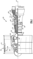
- FIG. 1 schematically illustrates a gas turbine engine 20.
- the gas turbine engine 20 is disclosed herein as a two-spool turbofan that generally incorporates a fan section 22, a compressor section 24, a combustor section 26, and a turbine section 28.
- Alternative engines might include an augmentor section (not shown) among other systems or features.
- the fan section 22 drives air along a bypass flow path B in a bypass duct defined within a fan case 15, and also drives air along a core flow path C for compression and communication into the combustor section 26 then expansion through the turbine section 28.
- the exemplary engine 20 generally includes a low speed spool 30 and a high speed spool 32 mounted for rotation about an engine central longitudinal axis A relative to an engine static structure 36 via several bearing systems 38. It should be understood that various bearing systems 38 at various locations may alternatively or additionally be provided, and the location of bearing systems 38 may be varied as appropriate to the application.
- the low speed spool 30 generally includes an inner shaft 40 that interconnects a fan 42, a first (or low) pressure compressor 44 and a first (or low) pressure turbine 46.
- the inner shaft 40 is connected to the fan 42 through a speed change mechanism, which in exemplary gas turbine engine 20 is illustrated as a geared architecture 48 to drive the fan 42 at a lower speed than the low speed spool 30.
- the high speed spool 32 includes an outer shaft 50 that interconnects a second (or high) pressure compressor 52 and a second (or high) pressure turbine 54.
- a combustor 56 is arranged in exemplary gas turbine 20 between the high pressure compressor 52 and the high pressure turbine 54.
- a mid-turbine frame 57 of the engine static structure 36 is arranged generally between the high pressure turbine 54 and the low pressure turbine 46.
- the mid-turbine frame 57 further supports bearing systems 38 in the turbine section 28.
- the inner shaft 40 and the outer shaft 50 are concentric and rotate via bearing systems 38 about the engine central longitudinal axis A which is collinear with their longitudinal axes.
- the core airflow is compressed by the low pressure compressor 44 then the high pressure compressor 52, mixed and burned with fuel in the combustor 56, then expanded over the high pressure turbine 54 and low pressure turbine 46.
- the mid-turbine frame 57 includes airfoils 59 which are in the core airflow path C.
- the turbines 46, 54 rotationally drive the respective low speed spool 30 and high speed spool 32 in response to the expansion.
- gear system 48 may be located aft of combustor section 26 or even aft of turbine section 28, and fan section 22 may be positioned forward or aft of the location of gear system 48.
- the engine 20 in one example is a high-bypass geared aircraft engine.
- the engine 20 bypass ratio is greater than about six (6), with an example embodiment being greater than about ten (10)
- the geared architecture 48 is an epicyclic gear train, such as a planetary gear system or other gear system, with a gear reduction ratio of greater than about 2.3
- the low pressure turbine 46 has a pressure ratio that is greater than about five.
- the engine 20 bypass ratio is greater than about ten (10:1)
- the fan diameter is significantly larger than that of the low pressure compressor 44
- the low pressure turbine 46 has a pressure ratio that is greater than about five 5:1.
- Low pressure turbine 46 pressure ratio is pressure measured prior to inlet of low pressure turbine 46 as related to the pressure at the outlet of the low pressure turbine 46 prior to an exhaust nozzle.
- the geared architecture 48 may be an epicycle gear train, such as a planetary gear system or other gear system, with a gear reduction ratio of greater than about 2.3:1. It should be understood, however, that the above parameters are only exemplary of one embodiment of a geared architecture engine and that the present invention is applicable to other gas turbine engines including direct drive turbofans.
- the fan section 22 of the engine 20 is designed for a particular flight condition -- typically cruise at about 0.8 Mach and about 35,000 feet (10,668 meters).
- the flight condition of 0.8 Mach and 35,000 ft (10,668 meters), with the engine at its best fuel consumption - also known as "bucket cruise Thrust Specific Fuel Consumption ('TSFC')" - is the industry standard parameter of lbm of fuel being burned divided by lbf of thrust the engine produces at that minimum point.
- "Low fan pressure ratio” is the pressure ratio across the fan blade alone, without a Fan Exit Guide Vane (“FEGV”) system.
- the low fan pressure ratio as disclosed herein according to one non-limiting embodiment is less than about 1.45.
- Low corrected fan tip speed is the actual fan tip speed in ft/sec divided by an industry standard temperature correction of [(Tram °R) / (518.7 °R)] 0.5 .
- the "Low corrected fan tip speed” as disclosed herein according to one non-limiting embodiment is less than about 1150 ft / second (350.5 meters/second).
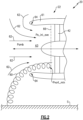
- Figure 2 is a schematic view of an air vortex 60 that arises between surface S (e.g., the ground, an aircraft fuselage, or aircraft wing) and an inlet of the gas turbine engine.
- the air vortex 60 is caused by crosswind and travels into the gas turbine engine 20, and is provoked by interference between engine airflow and the surface S.
- the air vortex 60 travels along with typical inlet airflow streamlines 62 into and within an airflow duct 63, to a reference section 66 in front of the fan 42 of the gas turbine engine 20, and travels towards the fan 42.
- the airflow duct 63 is at least partially defined by an inlet 61, which attaches to the fan case 15, or may be part of the fan case 15.
- the inlet 61 includes inlet lips 64 that will be discussed further below.
- the reference section 66 shown in Figure 2 is an example, and it is understood that other reference sections in front of the fan 42 and within the inlet 61 could be used.
- "in front of the fan” means fore of the fan 42 (i.e., towards a left side of Figure 2 ).
- Pamb corresponds to a total ambient air pressure
- Ps_inl_ave corresponds to an average (or “mean”) static air pressure in the reference section 66 in front of the fan 42 that is averaged for the reference area 66 at each engine rotational speed inlet corrected airflow, accordingly (e.g., in a plane in the reference area that is perpendicular to axis A).
- the total ambient pressure Pamb is a function of an ambient pressure in front of the fan 42 and air pressure introduced by aircraft speed VCAS (if the aircraft is moving).
- the mean static air pressure Ps_inl_ave can be defined either by averaging measured data (e.g., obtained, for instance, from static pressure tapes, arranged circumferentially in the airflow duct 63 on a duct outer diameter wall surface at the reference section 66, or can be defined by using predetermined engine performance airflow data in the reference section 66.
- the Pvort_min is minimum pressure in the vortex 60 at the reference section 66.
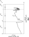
- Figure 3 is a graph that illustrates the effects of the air vortex 60 on inlet airflow distortion.
- the y-axis represents inlet airflow distortion according to the IDCmax distortion index discussed above, and the x-axis represents an inlet engine corrected airflow, normalized to the reference section 66 area, that corresponds to an engine power setting (WQ2AR measured in lbm/s/ft 2 ).
- Zone 1 the gas turbine engine 20 is operating on a low power setting , and there is an initial airflow separation on the inlet 64 lips of the gas turbine engine 20, followed by reattachment at 74 when engine power increases.
- the “separation” refers to the capture stream, so there are zones of inlet airflow separation, and the “reattachment” on Figure 3 .
- the x-axis airflow value at which the reattachment event 74 occurs depends on crosswind speed.
- Inlet separation Zone 2 (72B) on the graph 70 occurs during an engine high power setting, where there can again be airflow separation on the inlet lips 64 surface.
- the engine high power inlet airflow separation is most important for engine operability, and is generally not allowable in service.
- the inlet lips 64 and inlet 61 are shaped to avoid inlet airflow separation for Zone 2 at the engine high power setting during crosswind conditions.
- Zone 3 (72C) is in the range between lower and high engine power inlet airflow separation zones, and commences after airflow reattachment point at 74.
- Zone 3 air vortex distortions 78 occur, and are the dominant source of distortion.
- an air vortex 60 can be formed in Zone 1 and the Zone 2, where there is inlet airflow separation, inlet distortion from the air vortex 60 itself is not the dominant source of distortion in Zone 1 or Zone 2.
- Figure 4 is graph that illustrates air vortex minimum pressures near the center of an air vortex core, to illustrate found air vortex phenomena.
- Figure 4 contains two lines 82, 84 on the chart, formed by three data sets of measured pressures test points described below, each corresponding to Zone 3 (72C) of Figure 3 at crosswind speeds of 15-30 knots.
- Line 82 interpolates a first data set ( Pvort_min / Pamb ), which represents pressures measured near the center of the vortex 64 at reference section in front of fan ( Pvort_min ), and normalized by a total ambient pressure ( Pamb ).
- Line 84 interpolates a second data set and a third data.
- the second data set ( Ps_inl_ave / Pamb ) represents an average static pressure in reference section in front of fan ( Ps_inl_ave ), normalized by total ambient pressure ( Pamb ).
- the third data set ( Pvort_min / Ps_inl_ave ) represents a ratio of the pressure near center of vortex in reference section ( Pvort_min ) and an average static pressure in the reference section ( Ps_inl_ave ). This coincidence represents found air vortex pressure phenomena discussed in equations 1 and 2 below, which summarize a relationship between a minimum air pressure in the air vortex 60 ( Pvort_min ) and the terms Ps_inl_ave and the Pamb.
- Pvort _ min Ps _ inl _ ave Ps _ inl _ ave Pamb
- Pvort _ min Pamb Ps _ inl _ ave Pamb 2
- equations 1 and 2 can be applied to create a method of air vortex inlet distortion prediction for engine designing ( Figure 5 ), as well as for engine operability monitoring during engine bench test ( Figure 6 ), and flight tests and in service ( Figure 7 ).
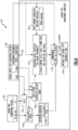
- FIG. 5 schematically illustrates a flowchart 100 that demonstrates an air vortex inlet prediction method for engine components during a design iteration loop.
- Customer requirements 102 are received that describe requirements and required operating conditions of a gas turbine engine 12.
- the customer requirements include Pamb, an ambient temperature Tamb, an aircraft speed VCAS (e.g., runway speed), thrust requirements, and a set of crosswind conditions 104 that includes a crosswind speed and a crosswind direction relative to the gas turbine engine 20.
- Aircraft speed VCAS is relevant because increased runway speed can diminish, or if sufficiently high, eliminate the effects of an air vortex.
- An engine performance model 106 models the performance of the gas turbine engine 20, and outputs three values: a ratio 108 between Ps_inl_ave and Pamb , W2AR , and N1C2.
- Ps_inl_ave was introduced above in Figure 2 , and corresponds to an average static air pressure in a reference area 66 of the fan section 22.
- W2AR corresponds to an airflow in the airflow duct 63 corrected to reference section 66 airflow parameters.
- N1C2 which corresponds to a rotational speed (N1) of the fan 42 or low pressure compressor 44, corrected to inlet airflow parameters in reference area 66.
- a distortion indicator D indic is determined at 110 as a function of the square of the ratio 108.
- D indic is a function of a minimum pressure near a center of the air vortex 60 defined via function of ratio 108.
- the distortion indicator D indic was found by the inventors to closely correlate with crosswind inlet model test data as measured by pressure probe rakes, and by comparison of the indicator with distortion, obtained during an engine test, and to provide a suitable alternative to using such rakes.
- a threshold D thresh represents a permissible amount of inlet airflow distortion at the reference area 66 for the set of crosswind conditions 104 (also shown as “crosswind data” in Figure 5 ).
- D thresh is determined at 112 as a function of W2AR , N1C2 , Pamb , the set of cross wind conditions 104, and the structural design and aerodynamic stability of the fan 42, based on a predetermined distortion threshold matrix (e.g., a lookup table).
- D thresh is also based on predetermined inlet distortion limits for the fan 42, low pressure compressor 44, and high pressure compressor 52 (as represented by W2AR allowable below).
- the distortion threshold value corresponds to an allowable fan structural Goodman value, which does not exceed 100%.
- the structure and aerodynamics of the fan 42 are represented by a set of engine components and system design features shown at 114, which includes an inlet configuration 116, a cross section of the reference area 66 in front of fan A2, WQ2AR (discussed above), W2AR allowable, a design 118 of the fan 42, low pressure compressor 44 and high pressure compressor 52, and an operability control logic that affects one or more control parameters (e.g., RPM, valve position, etc.).
- W2AR allowable represents a predetermined engine high power corrected airflow at which the airflow of the airflow duct 63 is separation free. The airflow depends on the inlet configuration 116, N1C2, Pamb, Tamb, VCAS, and the set of crosswind conditions 104.
- the regular inlet non-dimensional corrected allowable airflow, normalized to the reference area 66 in front of the fan 42 (WQ2AR) is not higher than 46 lbm/s/ft 2 .
- a comparison 120 is performed between D_indic and D_thresh. Based on the comparison 120 indicating that D_indic exceeds D_thresh, a first type of inlet airflow distortion notification 122 is provided, which may serve as an indication that the gas turbine engine design 114 is rejected. Based on the comparison 120 indicating that D_indic is below D_thresh, a second of inlet airflow distortion notification 124 is provided, which may serve as an indication that the gas turbine engine design 114 is approved.
- Figure 6 schematically illustrates a flowchart 140 that describes implementation of the method of Figure 5 during an engine bench test.
- a crosswind generator may be used to simulate actual crosswind conditions on the ground.
- the values Ps_inl_ave and N1 are provided from the gas turbine engine 20 and/or its associated powerplant system 142, instead of being derived from the engine performance model 106.
- N1 is corrected to N1C2 at 144, and Ps_inl_ave is utilized to obtain and square the ratio 108 from Figure 5 at 146 (or use another power in the range 1.98 - 2.02, as discussed above).
- the distortion indicator D indic is obtained at 110 based on the square of the ratio 108.
- An engine bench test acquisition system 148 is used to obtain ambient temperature Tamb, ambient pressure Pamb, and the set of crosswind conditions 104.
- Tamb is used to determine N1C2 at 144
- Pamb is used to determine the square of the ratio 108 at 146.
- N1C2, Tamb, and Pamb are used to obtain the airflow W2AR in the airflow duct 63 at 150.
- D thresh is determined at 112 as a function of W2AR, N1C2 , Pamb , the set of cross wind conditions 104, and the structure and aerodynamics of the fan 22.
- the inlet-corrected airflow threshold W2AR allowable (at which the airflow of the airflow duct 63 is separation free) is determined at 152 based on the data from the engine bench test acquisition system 148.
- D indic is compared to D thresh at 120, and if D indic exceeds D thresh, an inlet airflow distortion notification is provided at 154 to indicate an engine test operability risk (e.g., that a design of the fan 42 is rejected).
- an engine test monitoring computer may be used to perform the various steps enclosed within the dotted lines.
- FIG 7 schematically illustrates a flowchart 180 that describes implementation of the method of Figure 5 during an aircraft flight test.
- the flowchart 180 is similar to the flowchart 140 with a handful of differences, most notably that the speed VCAS is obtained from an engine / aircraft flight test acquisition system 182, and is used to determine N1C2 at 144 and to determine the square of the ratio 108 at 146.
- the set of crosswind conditions 104 are obtained from one or more sensors.
- VCAS is zero during a bench test, so it was not used in the flowchart 140 of Figure 6 .
- Another difference from the flowchart 140 is that the flowchart 180 uses additional system inputs, identified with reference numeral 182, as compared to the inputs to the flowchart 140.
- the notification 154 in the flowchart 180 includes a recommendation to a pilot to perform a rolling start, to mitigate the effects of an air vortex on the fan 42 and gas turbine engine 20.
- the notification 154 is only provided if the following conditions are also true:
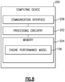
- FIG 8 schematically illustrates an example computing device 200 that may be used to perform steps of the flowcharts of Figures 5-7 .
- the computing device 200 includes processing circuitry 202 operatively connected to memory 204 and a communication interface 206.
- the processing circuitry 202 may include one or more microprocessors, microcontrollers, application specific integrated circuits (ASICs), or the like, for example.
- the memory 204 can include any one or combination of volatile memory elements (e.g., random access memory (RAM, such as DRAM, SRAM, SDRAM, VRAM, etc.)) and/or nonvolatile memory elements (e.g., ROM, hard drive, tape, CD-ROM, etc.). Moreover, the memory 204 may incorporate electronic, magnetic, optical, and/or other types of storage media. The memory 204 can also have a distributed architecture, where various components are situated remotely from one another, but can be accessed by the processing circuitry 202. The memory 204 may be used to store the engine performance model 106 of Figure 5 , for example.
- the communication interface 206 is configured to facilitate communication between the computing device 200 and other devices (e.g., sensors associated with the gas turbine engine, to receive measurements such as Pamb , Tamb , etc.).
- the computing device 200 may be configured to perform some or all of any of the steps of the flowcharts 100, 140, 180.
Landscapes
- Engineering & Computer Science (AREA)
- Chemical & Material Sciences (AREA)
- Combustion & Propulsion (AREA)
- Physics & Mathematics (AREA)
- General Physics & Mathematics (AREA)
- Mechanical Engineering (AREA)
- General Engineering & Computer Science (AREA)
- Aviation & Aerospace Engineering (AREA)
- Structures Of Non-Positive Displacement Pumps (AREA)
- Control Of Positive-Displacement Air Blowers (AREA)
Abstract
Description
- This application relates to gas turbine engines, and more particularly to monitoring inlet airflow distortion of gas turbine engines for engine design and engine operability monitoring during engine bench tests, during flight tests, and/or in service.
- Gas turbine engines are known and typically include a fan delivering air into a bypass duct for propulsion. The fan also delivers air into a compressor where air is compressed and delivered into a combustor. The air is mixed with fuel and ignited. Products of this combustion pass downstream over turbine rotors driving them to rotate. The turbine rotors, in turn, rotate compressor rotors and the fan rotor.
- An air vortex can arise between a surface (e.g., a ground plane, aircraft fuselage, or aircraft wing) and the engine inlet when the engine is operating on the ground in crosswind conditions. The air vortex may be propagated from the surface into the inlet duct, thereby creating inlet airflow distortion in front of the fan, which increase fan blades structural stress, and can also call engine gas dynamic instability.
- It is known to quantity the magnitude of inlet airflow distortion using a distortion index such as IDCmax or DC60, as discussed in Bissinger, N. C., & Breuer, T. (2010). "Basic Principles - Gas Turbine Compatibility - Intake Aerodynamic Aspects." Encyclopedia of Aerospace Engineering, Volume 8, Chapter EAE487 and Seddon, J., & Goldsmith, E. L. (1985). "Intake aerodynamics." AIAA education series, New York.
- In the prior art, determining the magnitude of inlet airflow distortion required the use of distortion probe rakes arranged circumferentially within a gas turbine engine taking measurements during actual operation of the gas turbine engine.
- A method for a gas turbine engine according to an aspect of the present invention includes calculating an inlet airflow distortion value at a reference area within an airflow duct of a gas turbine engine and in front of a fan of the gas turbine engine. The inlet airflow distortion value is indicative of an air pressure of an air vortex at the reference area caused by a set of crosswind conditions. The calculating is based on a ratio between an inlet airflow static air pressure in the reference area and a total ambient air pressure. The method also includes comparing the inlet airflow distortion value to a threshold corresponding to a permissible amount of inlet airflow distortion at the reference area for the set of crosswind conditions and, based on the comparison indicating that the inlet airflow distortion exceeds the threshold, providing an inlet airflow distortion notification.
- In an embodiment of the above, the inlet airflow static air pressure is an average of a plurality of inlet airflow static pressures corresponding to a plurality of rotational speeds of the fan.
- In an embodiment according to any of the previous embodiments, during a simulated test of the gas turbine engine experiencing the set of crosswind conditions, the inlet airflow static air pressure at the reference area is determined based on an engine performance model.
- In an embodiment according to any of the previous embodiments, the notification comprises an indication that a design of the fan is rejected.
- In an embodiment according to any of the previous embodiments, during a bench test or actual runway procedure, the inlet airflow static pressure at the reference area is determined based on measured operational data from the gas turbine engine or its associated powerplant system.
- In an embodiment according to any of the previous embodiments, the inlet airflow static air pressure is determined during runway operation of an aircraft that includes the gas turbine engine and is experiencing the set of crosswind conditions, and the inlet airflow distortion notification includes a recommendation to a pilot of an aircraft that includes the gas turbine engine to perform a rolling start takeoff.
- In an embodiment according to any of the previous embodiments, the method includes determining the threshold based on the set of crosswind conditions, a magnitude of airflow to the fan, and a rotational speed of a component of the gas turbine engine.
- In an embodiment according to any of the previous embodiments, during an actual runway procedure, the threshold is determined further based on a current runway speed of an aircraft that includes the gas turbine engine.
- A system for a gas turbine engine according to an aspect of the present invention includes processing circuitry operatively connected to memory. The processor is configured to calculate an inlet airflow distortion value at a reference area within an airflow duct of a gas turbine engine and in front of a fan of the gas turbine engine. The inlet airflow distortion value is indicative of an air pressure of an air vortex at the reference area caused by a set of crosswind conditions. The calculation is based on a ratio between an inlet airflow static air pressure at the reference area and a total ambient air pressure. The processor is also configured to compare the inlet airflow distortion value to a threshold corresponding to a permissible amount of inlet airflow distortion at the reference area for the set of crosswind conditions and, based on the comparison indicating that the inlet airflow distortion exceeds the threshold, provide an inlet airflow distortion notification.
- In an embodiment of the above, the inlet airflow static air pressure is an average of a plurality of inlet airflow static pressures corresponding to a plurality of rotational speeds of the fan.
- In an embodiment according to any of the previous embodiments, the processing circuitry is configured to, during a simulated test of the gas turbine engine experiencing the set of crosswind conditions, determine the inlet airflow static air pressure at the reference area based on an engine performance model.
- In an embodiment according to any of the previous embodiments, the notification comprises an indication that a design of the fan is rejected.
- In an embodiment according to any of the previous embodiments, the processing circuitry is configured to, during a bench test or actual runway procedure, determine the inlet airflow static pressure at the reference area based on measured operational data from the gas turbine engine or its associated powerplant system.
- In an embodiment according to any of the previous embodiments, the inlet airflow static air pressure is determined during runway operation of an aircraft that includes the gas turbine engine and is experiencing the set of crosswind conditions. The inlet airflow distortion notification includes a recommendation to a pilot of an aircraft that includes the gas turbine engine to perform a rolling start takeoff.
- In an embodiment according to any of the previous embodiments, the processing circuitry is configured to determine the threshold based on the set of crosswind conditions, a magnitude of airflow to the fan, and a rotational speed of a component of the gas turbine engine.
- In an embodiment according to any of the previous embodiments, the processing circuitry is configured to, during an actual runway procedure, determine the threshold further based on a current runway speed of an aircraft that includes the gas turbine engine.
- A method for a gas turbine engine according to an aspect of the present invention includes calculating an inlet airflow distortion value at a reference area within an airflow duct of a gas turbine engine and in front of a fan of the gas turbine engine. The inlet airflow distortion value is indicative of an air pressure of an air vortex at the reference area caused by a set of crosswind conditions. The calculating is based on a square of a ratio between an inlet airflow static air pressure at the reference area and a total ambient air pressure. The method also includes comparing the inlet airflow distortion value to a threshold corresponding to a permissible amount of inlet airflow distortion at the reference area for the set of crosswind conditions and, based on the comparison indicating that the inlet airflow distortion exceeds the threshold, providing an inlet airflow distortion notification.
- In embodiment of the above, the inlet airflow static air pressure is an average of a plurality of inlet airflow static pressures corresponding to a plurality of rotational speeds of the fan.
- In an embodiment according to any of the previous embodiments, the method also includes determining the threshold based on the set of crosswind conditions, a magnitude of airflow to the fan, and a rotational speed of a component of the gas turbine engine.
- In an embodiment according to any of the previous embodiments, during an actual runway procedure, the threshold is determined further based on a current runway speed of an aircraft that includes the gas turbine engine.
- The embodiments, examples, and alternatives of the preceding paragraphs, the claims, or the following description and drawings, including any of their various aspects or respective individual features, may be taken independently or in any combination. Features described in connection with one embodiment are applicable to all embodiments, unless such features are incompatible.
-
-
Figure 1 is a schematic view of an example gas turbine engine. -
Figure 2 is a schematic view of an air vortex traveling into the gas turbine engine ofFigure 1 . -
Figure 3 is a graph that illustrates the effects of an air vortex on inlet airflow distortion. -
Figure 4 is graph that illustrates air vortex minimum pressures near the center of an air vortex core, to illustrate found air vortex phenomena. -
Figure 5 schematically illustrates a flowchart that demonstrates an air vortex inlet prediction method for engine components during a design iteration loop. -
Figure 6 schematically illustrates a flowchart that describes implementation of the method ofFigure 5 during an engine bench test. -
Figure 7 schematically illustrates a flowchart that describes implementation of the method ofFigure 5 during an aircraft flight test. -
Figure 8 schematically illustrates an example computing device that may be used to perform steps of the flowcharts ofFigures 5-7 . -
Figure 1 schematically illustrates agas turbine engine 20. Thegas turbine engine 20 is disclosed herein as a two-spool turbofan that generally incorporates afan section 22, acompressor section 24, a combustor section 26, and aturbine section 28. Alternative engines might include an augmentor section (not shown) among other systems or features. Thefan section 22 drives air along a bypass flow path B in a bypass duct defined within afan case 15, and also drives air along a core flow path C for compression and communication into the combustor section 26 then expansion through theturbine section 28. Although depicted as a two-spool turbofan gas turbine engine in the disclosed non-limiting embodiment, it should be understood that the concepts described herein are not limited to use with two-spool turbofans as the teachings may be applied to other types of turbine engines including three-spool architectures. - The
exemplary engine 20 generally includes alow speed spool 30 and ahigh speed spool 32 mounted for rotation about an engine central longitudinal axis A relative to an enginestatic structure 36 viaseveral bearing systems 38. It should be understood that various bearingsystems 38 at various locations may alternatively or additionally be provided, and the location of bearingsystems 38 may be varied as appropriate to the application. - The
low speed spool 30 generally includes aninner shaft 40 that interconnects afan 42, a first (or low) pressure compressor 44 and a first (or low)pressure turbine 46. Theinner shaft 40 is connected to thefan 42 through a speed change mechanism, which in exemplarygas turbine engine 20 is illustrated as a gearedarchitecture 48 to drive thefan 42 at a lower speed than thelow speed spool 30. Thehigh speed spool 32 includes anouter shaft 50 that interconnects a second (or high)pressure compressor 52 and a second (or high)pressure turbine 54. Acombustor 56 is arranged inexemplary gas turbine 20 between thehigh pressure compressor 52 and thehigh pressure turbine 54. Amid-turbine frame 57 of the enginestatic structure 36 is arranged generally between thehigh pressure turbine 54 and thelow pressure turbine 46. Themid-turbine frame 57 furthersupports bearing systems 38 in theturbine section 28. Theinner shaft 40 and theouter shaft 50 are concentric and rotate via bearingsystems 38 about the engine central longitudinal axis A which is collinear with their longitudinal axes. - The core airflow is compressed by the low pressure compressor 44 then the
high pressure compressor 52, mixed and burned with fuel in thecombustor 56, then expanded over thehigh pressure turbine 54 andlow pressure turbine 46. Themid-turbine frame 57 includesairfoils 59 which are in the core airflow path C. Theturbines low speed spool 30 andhigh speed spool 32 in response to the expansion. It will be appreciated that each of the positions of thefan section 22,compressor section 24, combustor section 26,turbine section 28, and fandrive gear system 48 may be varied. For example,gear system 48 may be located aft of combustor section 26 or even aft ofturbine section 28, andfan section 22 may be positioned forward or aft of the location ofgear system 48. - The
engine 20 in one example is a high-bypass geared aircraft engine. In a further example, theengine 20 bypass ratio is greater than about six (6), with an example embodiment being greater than about ten (10), the gearedarchitecture 48 is an epicyclic gear train, such as a planetary gear system or other gear system, with a gear reduction ratio of greater than about 2.3 and thelow pressure turbine 46 has a pressure ratio that is greater than about five. In one disclosed embodiment, theengine 20 bypass ratio is greater than about ten (10:1), the fan diameter is significantly larger than that of the low pressure compressor 44, and thelow pressure turbine 46 has a pressure ratio that is greater than about five 5:1.Low pressure turbine 46 pressure ratio is pressure measured prior to inlet oflow pressure turbine 46 as related to the pressure at the outlet of thelow pressure turbine 46 prior to an exhaust nozzle. The gearedarchitecture 48 may be an epicycle gear train, such as a planetary gear system or other gear system, with a gear reduction ratio of greater than about 2.3:1. It should be understood, however, that the above parameters are only exemplary of one embodiment of a geared architecture engine and that the present invention is applicable to other gas turbine engines including direct drive turbofans. - A significant amount of thrust is provided by the bypass flow B due to the high bypass ratio. The
fan section 22 of theengine 20 is designed for a particular flight condition -- typically cruise at about 0.8 Mach and about 35,000 feet (10,668 meters). The flight condition of 0.8 Mach and 35,000 ft (10,668 meters), with the engine at its best fuel consumption - also known as "bucket cruise Thrust Specific Fuel Consumption ('TSFC')" - is the industry standard parameter of lbm of fuel being burned divided by lbf of thrust the engine produces at that minimum point. "Low fan pressure ratio" is the pressure ratio across the fan blade alone, without a Fan Exit Guide Vane ("FEGV") system. The low fan pressure ratio as disclosed herein according to one non-limiting embodiment is less than about 1.45. "Low corrected fan tip speed" is the actual fan tip speed in ft/sec divided by an industry standard temperature correction of [(Tram °R) / (518.7 °R)]0.5. The "Low corrected fan tip speed" as disclosed herein according to one non-limiting embodiment is less than about 1150 ft / second (350.5 meters/second). -
Figure 2 is a schematic view of anair vortex 60 that arises between surface S (e.g., the ground, an aircraft fuselage, or aircraft wing) and an inlet of the gas turbine engine. Theair vortex 60 is caused by crosswind and travels into thegas turbine engine 20, and is provoked by interference between engine airflow and the surface S. Theair vortex 60 travels along with typical inlet airflow streamlines 62 into and within anairflow duct 63, to areference section 66 in front of thefan 42 of thegas turbine engine 20, and travels towards thefan 42. Theairflow duct 63 is at least partially defined by aninlet 61, which attaches to thefan case 15, or may be part of thefan case 15. Theinlet 61 includesinlet lips 64 that will be discussed further below. Thereference section 66 shown inFigure 2 is an example, and it is understood that other reference sections in front of thefan 42 and within theinlet 61 could be used. As used herein, "in front of the fan" means fore of the fan 42 (i.e., towards a left side ofFigure 2 ). - In
Figure 2 , Pamb corresponds to a total ambient air pressure, and Ps_inl_ave corresponds to an average (or "mean") static air pressure in thereference section 66 in front of thefan 42 that is averaged for thereference area 66 at each engine rotational speed inlet corrected airflow, accordingly (e.g., in a plane in the reference area that is perpendicular to axis A). The total ambient pressure Pamb is a function of an ambient pressure in front of thefan 42 and air pressure introduced by aircraft speed VCAS (if the aircraft is moving). The mean static air pressure Ps_inl_ave can be defined either by averaging measured data (e.g., obtained, for instance, from static pressure tapes, arranged circumferentially in theairflow duct 63 on a duct outer diameter wall surface at thereference section 66, or can be defined by using predetermined engine performance airflow data in thereference section 66. The Pvort_min is minimum pressure in thevortex 60 at thereference section 66. -
Figure 3 is a graph that illustrates the effects of theair vortex 60 on inlet airflow distortion. The y-axis represents inlet airflow distortion according to the IDCmax distortion index discussed above, and the x-axis represents an inlet engine corrected airflow, normalized to thereference section 66 area, that corresponds to an engine power setting (WQ2AR measured in lbm/s/ft2). - There are three distinctive zones on the
chart 70, namely Zone 1 (72A), Zone 2 (72B), and Zone 3 (72C). DuringZone 1, thegas turbine engine 20 is operating on a low power setting , and there is an initial airflow separation on theinlet 64 lips of thegas turbine engine 20, followed by reattachment at 74 when engine power increases. - The "separation" refers to the capture stream, so there are zones of inlet airflow separation, and the "reattachment" on
Figure 3 . The x-axis airflow value at which the reattachment event 74 occurs depends on crosswind speed. - Inlet separation Zone 2 (72B) on the
graph 70 occurs during an engine high power setting, where there can again be airflow separation on theinlet lips 64 surface. The engine high power inlet airflow separation is most important for engine operability, and is generally not allowable in service. Theinlet lips 64 andinlet 61 are shaped to avoid inlet airflow separation forZone 2 at the engine high power setting during crosswind conditions. - Zone 3 (72C) is in the range between lower and high engine power inlet airflow separation zones, and commences after airflow reattachment point at 74. During Zone 3,
air vortex distortions 78 occur, and are the dominant source of distortion. Although anair vortex 60 can be formed inZone 1 and theZone 2, where there is inlet airflow separation, inlet distortion from theair vortex 60 itself is not the dominant source of distortion inZone 1 orZone 2. - Traditionally, distortion probe rakes have been necessary to detect air vortex distortions during Zone 3, but the techniques discussed below do not have this requirement. In particular, the techniques discussed herein allow for prediction, designing, and engine validation work stages without requiring distortion probe rake measurements.
-
Figure 4 is graph that illustrates air vortex minimum pressures near the center of an air vortex core, to illustrate found air vortex phenomena.Figure 4 contains twolines Figure 3 at crosswind speeds of 15-30 knots. -
Line 82 interpolates a first data set (Pvort_min / Pamb), which represents pressures measured near the center of thevortex 64 at reference section in front of fan (Pvort_min), and normalized by a total ambient pressure (Pamb). -
Line 84 interpolates a second data set and a third data. The second data set (Ps_inl_ave / Pamb) represents an average static pressure in reference section in front of fan (Ps_inl_ave), normalized by total ambient pressure (Pamb). - The third data set (Pvort_min / Ps_inl_ave) represents a ratio of the pressure near center of vortex in reference section (Pvort_min) and an average static pressure in the reference section (Ps_inl_ave). This coincidence represents found air vortex pressure phenomena discussed in
equations 

- In both
equations equation 2, it is understood that this is an example, and that another power could be used in the range of 1.98 - 2.02. - The relationships represented in
equations Figure 5 ), as well as for engine operability monitoring during engine bench test (Figure 6 ), and flight tests and in service (Figure 7 ). -
Figure 5 schematically illustrates aflowchart 100 that demonstrates an air vortex inlet prediction method for engine components during a design iteration loop.Customer requirements 102 are received that describe requirements and required operating conditions of agas turbine engine 12. The customer requirements include Pamb, an ambient temperature Tamb, an aircraft speed VCAS (e.g., runway speed), thrust requirements, and a set ofcrosswind conditions 104 that includes a crosswind speed and a crosswind direction relative to thegas turbine engine 20. Aircraft speed VCAS is relevant because increased runway speed can diminish, or if sufficiently high, eliminate the effects of an air vortex. - An
engine performance model 106 models the performance of thegas turbine engine 20, and outputs three values: aratio 108 between Ps_inl_ave and Pamb, W2AR, and N1C2. Ps_inl_ave was introduced above inFigure 2 , and corresponds to an average static air pressure in areference area 66 of thefan section 22. W2AR corresponds to an airflow in theairflow duct 63 corrected toreference section 66 airflow parameters. N1C2 which corresponds to a rotational speed (N1) of thefan 42 or low pressure compressor 44, corrected to inlet airflow parameters inreference area 66. - A distortion indicator D indic is determined at 110 as a function of the square of the
ratio 108. Thus D indic is a function of a minimum pressure near a center of theair vortex 60 defined via function ofratio 108. The distortion indicator D indic was found by the inventors to closely correlate with crosswind inlet model test data as measured by pressure probe rakes, and by comparison of the indicator with distortion, obtained during an engine test, and to provide a suitable alternative to using such rakes. - Referring again to
Figure 5 , a threshold D thresh represents a permissible amount of inlet airflow distortion at thereference area 66 for the set of crosswind conditions 104 (also shown as "crosswind data" inFigure 5 ). D thresh is determined at 112 as a function of W2AR, N1C2, Pamb, the set ofcross wind conditions 104, and the structural design and aerodynamic stability of thefan 42, based on a predetermined distortion threshold matrix (e.g., a lookup table). D thresh is also based on predetermined inlet distortion limits for thefan 42, low pressure compressor 44, and high pressure compressor 52 (as represented by W2AR allowable below). In one or more embodiments, the distortion threshold value corresponds to an allowable fan structural Goodman value, which does not exceed 100%. - To elaborate, the structure and aerodynamics of the
fan 42 are represented by a set of engine components and system design features shown at 114, which includes aninlet configuration 116, a cross section of thereference area 66 in front of fan A2, WQ2AR (discussed above), W2AR allowable, adesign 118 of thefan 42, low pressure compressor 44 andhigh pressure compressor 52, and an operability control logic that affects one or more control parameters (e.g., RPM, valve position, etc.). W2AR allowable represents a predetermined engine high power corrected airflow at which the airflow of theairflow duct 63 is separation free. The airflow depends on theinlet configuration 116, N1C2, Pamb, Tamb, VCAS, and the set ofcrosswind conditions 104. In one example, the regular inlet non-dimensional corrected allowable airflow, normalized to thereference area 66 in front of the fan 42 (WQ2AR), is not higher than 46 lbm/s/ft2. - A
comparison 120 is performed between D_indic and D_thresh. Based on thecomparison 120 indicating that D_indic exceeds D_thresh, a first type of inletairflow distortion notification 122 is provided, which may serve as an indication that the gasturbine engine design 114 is rejected. Based on thecomparison 120 indicating that D_indic is below D_thresh, a second of inletairflow distortion notification 124 is provided, which may serve as an indication that the gasturbine engine design 114 is approved. -
Figure 6 schematically illustrates aflowchart 140 that describes implementation of the method ofFigure 5 during an engine bench test. During such a bench test, a crosswind generator may be used to simulate actual crosswind conditions on the ground. In this example, the values Ps_inl_ave and N1 are provided from thegas turbine engine 20 and/or its associatedpowerplant system 142, instead of being derived from theengine performance model 106. - N1 is corrected to N1C2 at 144, and Ps_inl_ave is utilized to obtain and square the
ratio 108 fromFigure 5 at 146 (or use another power in the range 1.98 - 2.02, as discussed above). The distortion indicator D indic is obtained at 110 based on the square of theratio 108. - An engine bench
test acquisition system 148 is used to obtain ambient temperature Tamb, ambient pressure Pamb, and the set ofcrosswind conditions 104. Tamb is used to determine N1C2 at 144, and Pamb is used to determine the square of theratio 108 at 146. N1C2, Tamb, and Pamb are used to obtain the airflow W2AR in theairflow duct 63 at 150. As inFigure 5 , D thresh is determined at 112 as a function of W2AR, N1C2, Pamb, the set ofcross wind conditions 104, and the structure and aerodynamics of thefan 22. - The inlet-corrected airflow threshold W2AR allowable (at which the airflow of the
airflow duct 63 is separation free) is determined at 152 based on the data from the engine benchtest acquisition system 148. - D indic is compared to D thresh at 120, and if D indic exceeds D thresh, an inlet airflow distortion notification is provided at 154 to indicate an engine test operability risk (e.g., that a design of the
fan 42 is rejected). As shown inFigure 6 , an engine test monitoring computer may be used to perform the various steps enclosed within the dotted lines. -
Figure 7 schematically illustrates aflowchart 180 that describes implementation of the method ofFigure 5 during an aircraft flight test. Theflowchart 180 is similar to theflowchart 140 with a handful of differences, most notably that the speed VCAS is obtained from an engine / aircraft flighttest acquisition system 182, and is used to determine N1C2 at 144 and to determine the square of theratio 108 at 146. Here, the set ofcrosswind conditions 104 are obtained from one or more sensors. VCAS is zero during a bench test, so it was not used in theflowchart 140 ofFigure 6 . Another difference from theflowchart 140 is that theflowchart 180 uses additional system inputs, identified withreference numeral 182, as compared to the inputs to theflowchart 140. - In one example, the
notification 154 in theflowchart 180 includes a recommendation to a pilot to perform a rolling start, to mitigate the effects of an air vortex on thefan 42 andgas turbine engine 20. - In one example, the
notification 154 is only provided if the following conditions are also true: - W2AR < W2AR allowable,
- VCAS < VCAS_rolling_start (a rolling start runway speed that is at least 35 knots),
- The landing gear strut compression signal is ON (indicating that an aircraft that includes the
gas turbine engine 20 is on the ground) (see 182 inFigure 7 ), - a Lift ON signal is ON (see 182 in
Figure 7 ), which is indicative of a flight condition (e.g., take-off or landing), and - a thrust reverser stowed signal is ON (see 182 in
Figure 7 ). -
Figure 8 schematically illustrates anexample computing device 200 that may be used to perform steps of the flowcharts ofFigures 5-7 . Thecomputing device 200 includesprocessing circuitry 202 operatively connected tomemory 204 and acommunication interface 206. Theprocessing circuitry 202 may include one or more microprocessors, microcontrollers, application specific integrated circuits (ASICs), or the like, for example. - The
memory 204 can include any one or combination of volatile memory elements (e.g., random access memory (RAM, such as DRAM, SRAM, SDRAM, VRAM, etc.)) and/or nonvolatile memory elements (e.g., ROM, hard drive, tape, CD-ROM, etc.). Moreover, thememory 204 may incorporate electronic, magnetic, optical, and/or other types of storage media. Thememory 204 can also have a distributed architecture, where various components are situated remotely from one another, but can be accessed by theprocessing circuitry 202. Thememory 204 may be used to store theengine performance model 106 ofFigure 5 , for example. - The
communication interface 206 is configured to facilitate communication between thecomputing device 200 and other devices (e.g., sensors associated with the gas turbine engine, to receive measurements such as Pamb, Tamb, etc.). Thecomputing device 200 may be configured to perform some or all of any of the steps of theflowcharts - The techniques discussed herein for assessing inlet airflow distortion offer improvements over the prior art, as detailed inlet duct flow field pressure measurements are not required. As a result,
gas turbine engine 20 design validation can be performed more efficiently, saving time and reducing cost. - Although example embodiments have been disclosed, a worker of ordinary skill in this art would recognize that certain modifications would come within the scope of this disclosure. For that reason, the following claims should be studied to determine the scope and content of this disclosure.
Claims (15)
- A method for a gas turbine engine, comprising:calculating an inlet airflow distortion value at a reference area (66) within an airflow duct (63) of a gas turbine engine (20) and in front of a fan (42) of the gas turbine engine (20), the inlet airflow distortion value indicative of an air pressure of an air vortex (60) at the reference area (66) caused by a set of crosswind conditions (104), said calculating based on a ratio (108) between an inlet airflow static air pressure (Ps_inl_ave) in the reference area (66) and a total ambient air pressure (Pamb);comparing the inlet airflow distortion value to a threshold (D_thresh) corresponding to a permissible amount of inlet airflow distortion at the reference area (66) for the set of crosswind conditions (104); andbased on the comparison (120) indicating that the inlet airflow distortion exceeds the threshold (D_thresh), providing an inlet airflow distortion notification (122).
- The method of claim 1, wherein the inlet airflow static air pressure (Ps_inl_ave) is an average of a plurality of inlet airflow static pressures corresponding to a plurality of rotational speeds (N1) of the fan (42).
- The method of claim 1 or 2, wherein during a simulated test of the gas turbine engine (20) experiencing the set of crosswind conditions (104), the inlet airflow static air pressure (Ps_inl_ave) at the reference area (66) is determined based on an engine performance model (106).
- The method of any preceding claim, wherein the notification (122) comprises an indication that a design of the fan (42) is rejected.
- The method of any preceding claim, wherein during a bench test or actual runway procedure, the inlet airflow static pressure at the reference area (66) is determined based on measured operational data from the gas turbine engine (20) or its associated powerplant system (142).
- The method of any preceding claim, wherein:the inlet airflow static air pressure (Ps_inl_ave) is determined during runway operation of an aircraft that includes the gas turbine engine (20) and is experiencing the set of crosswind conditions (104); andthe inlet airflow distortion notification (122) includes a recommendation to a pilot of an aircraft that includes the gas turbine engine (20) to perform a rolling start takeoff.
- The method of any preceding claim, comprising determining the threshold (D thresh) based on the set of crosswind conditions (104), a magnitude of airflow to the fan (42), and a rotational speed of a component of the gas turbine engine (20), optionally wherein during an actual runway procedure, the threshold (D thresh) is determined further based on a current runway speed of an aircraft that includes the gas turbine engine (20).
- A system for a gas turbine engine, comprising:
processing circuitry (202) operatively connected to memory (204), the processing circuitry (202) configured to:calculate an inlet airflow distortion value at a reference area (66) within an airflow duct (63) of a gas turbine engine (20) and in front of a fan (42) of the gas turbine engine (20), the inlet airflow distortion value indicative of an air pressure of an air vortex (60) at the reference area (66) caused by a set of crosswind conditions (104), the calculation based on a ratio (108) between an inlet airflow static air pressure (Ps_inl_ave) at the reference area (66) and a total ambient air pressure (Pamb);compare the inlet airflow distortion value to a threshold (D_thresh) corresponding to a permissible amount of inlet airflow distortion at the reference area (66) for the set of crosswind conditions (104); andbased on the comparison (120) indicating that the inlet airflow distortion exceeds the threshold (D_thresh), provide an inlet airflow distortion notification (122). - The system of claim 8, wherein the inlet airflow static air pressure (Ps_inl_ave) is an average of a plurality of inlet airflow static pressures corresponding to a plurality of rotational speeds (N1) of the fan (42).
- The system of claim 8 or 9, wherein the processing circuitry (202) is configured to:during a simulated test of the gas turbine engine (20) experiencing the set of crosswind conditions (104), determine the inlet airflow static air pressure (Ps_inl_ave) at the reference area (66) based on an engine performance model (106); and/orduring a bench test or actual runway procedure, determine the inlet airflow static pressure at the reference area (66) based on measured operational data from the gas turbine engine (20) or its associated powerplant system (142).
- The system of any of claims 8 to 10, wherein the notification (122) comprises an indication that a design of the fan (42) is rejected.
- The system of any of claims 8 to 11, wherein:the inlet airflow static air pressure (Ps_inl_ave) is determined during runway operation of an aircraft that includes the gas turbine engine (20) and is experiencing the set of crosswind conditions (104); andthe inlet airflow distortion notification (122) includes a recommendation to a pilot of an aircraft that includes the gas turbine engine (20) to perform a rolling start takeoff.
- The system of any of claims 8 to 12, wherein the processing circuitry (202) is configured to determine the threshold (D thresh) based on the set of crosswind conditions (104), a magnitude of airflow to the fan (42), and a rotational speed of a component of the gas turbine engine (20), optionally wherein the processing circuitry (202) is configured to, during an actual runway procedure, determine the threshold (D thresh) further based on a current runway speed of an aircraft that includes the gas turbine engine (20).
- A method for a gas turbine engine, comprising:calculating an inlet airflow distortion value at a reference area (66) within an airflow duct (63) of a gas turbine engine (20) and in front of a fan (42) of the gas turbine engine (20), the inlet airflow distortion value indicative of an air pressure of an air vortex (60) at the reference area (66) caused by a set of crosswind conditions (104), said calculating based on a square of a ratio (108) between an inlet airflow static air pressure (Ps_inl_ave) at the reference area (66) and a total ambient air pressure (Pamb);comparing the inlet airflow distortion value to a threshold (D thresh) corresponding to a permissible amount of inlet airflow distortion at the reference area (66) for the set of crosswind conditions (104); andbased on the comparison (120) indicating that the inlet airflow distortion exceeds the threshold (D thresh), providing an inlet airflow distortion notification (122), and optionally:
determining the threshold (D thresh) based on the set of crosswind conditions (104), a magnitude of airflow to the fan (42), and a rotational speed of a component of the gas turbine engine (20). - The method of claim 14, wherein:the inlet airflow static air pressure (Ps_inl_ave) is an average of a plurality of inlet airflow static pressures corresponding to a plurality of rotational speeds (N1) of the fan (42), and/orduring an actual runway procedure, the threshold (D thresh) is determined further based on a current runway speed of an aircraft that includes the gas turbine engine (20).
Applications Claiming Priority (1)
| Application Number | Priority Date | Filing Date | Title |
|---|---|---|---|
| US18/215,432 US12510438B2 (en) | 2023-06-28 | 2023-06-28 | Method of inlet distortion prediction and monitoring |
Publications (2)
| Publication Number | Publication Date |
|---|---|
| EP4484715A2 true EP4484715A2 (en) | 2025-01-01 |
| EP4484715A3 EP4484715A3 (en) | 2025-08-06 |
Family
ID=91670432
Family Applications (1)
| Application Number | Title | Priority Date | Filing Date |
|---|---|---|---|
| EP24184283.0A Pending EP4484715A3 (en) | 2023-06-28 | 2024-06-25 | Method of inlet distortion prediction and monitoring |
Country Status (2)
| Country | Link |
|---|---|
| US (1) | US12510438B2 (en) |
| EP (1) | EP4484715A3 (en) |
Cited By (1)
| Publication number | Priority date | Publication date | Assignee | Title |
|---|---|---|---|---|
| CN120721385A (en) * | 2025-08-25 | 2025-09-30 | 中国航发沈阳发动机研究所 | A steady-state temperature distortion intake duct and its design method |
Families Citing this family (1)
| Publication number | Priority date | Publication date | Assignee | Title |
|---|---|---|---|---|
| US12503978B1 (en) * | 2024-06-21 | 2025-12-23 | Rolls-Royce North American Technologies Inc. | Inlets for gas turbine engine fans with distortion tolerance |
Family Cites Families (9)
| Publication number | Priority date | Publication date | Assignee | Title |
|---|---|---|---|---|
| US9169779B2 (en) * | 2007-10-09 | 2015-10-27 | United Technologies Corp. | Systems and methods for altering inlet airflow of gas turbine engines |
| RU2397496C1 (en) | 2009-02-05 | 2010-08-20 | Федеральное государственное унитарное предприятие "Лётно-исследовательский институт имени М.М. Громова" | Procedure for visualisation of space and ground air flows under air intake of operating gas-turbine engine |
| US10753278B2 (en) * | 2016-03-30 | 2020-08-25 | General Electric Company | Translating inlet for adjusting airflow distortion in gas turbine engine |
| US10279918B2 (en) | 2016-08-31 | 2019-05-07 | The Boeing Company | Methods and apparatus to control thrust ramping of an aircraft engine |
| US11047395B2 (en) | 2017-08-24 | 2021-06-29 | Raytheon Technologies Corporation | Fan stress tracking for turbofan gas turbine engines |
| US11027827B2 (en) | 2018-09-04 | 2021-06-08 | Raytheon Technologies Corporation | Method for separated flow detection |
| US20200080477A1 (en) | 2018-09-07 | 2020-03-12 | United Technologies Corporation | Prediction of inlet distortion of boundary layer ingesting propulsion system |
| CN111079232A (en) | 2019-11-15 | 2020-04-28 | 南京航空航天大学 | Calculation method for predicting influence of rotational flow distortion air intake on performance of aircraft engine |
| US11828237B2 (en) | 2020-04-28 | 2023-11-28 | General Electric Company | Methods and apparatus to control air flow separation of an engine |
-
2023
- 2023-06-28 US US18/215,432 patent/US12510438B2/en active Active
-
2024
- 2024-06-25 EP EP24184283.0A patent/EP4484715A3/en active Pending
Non-Patent Citations (2)
| Title |
|---|
| BISSINGER, N. C.BREUER, T: "Encyclopedia of Aerospace Engineering", vol. 8, 2010, article "Basic Principles - Gas Turbine Compatibility - Intake Aerodynamic Aspects" |
| SEDDON, J.GOLDSMITH, E. L: "Intake aerodynamics", AIAA EDUCATION SERIES, 1985 |
Cited By (1)
| Publication number | Priority date | Publication date | Assignee | Title |
|---|---|---|---|---|
| CN120721385A (en) * | 2025-08-25 | 2025-09-30 | 中国航发沈阳发动机研究所 | A steady-state temperature distortion intake duct and its design method |
Also Published As
| Publication number | Publication date |
|---|---|
| US12510438B2 (en) | 2025-12-30 |
| EP4484715A3 (en) | 2025-08-06 |
| US20250003835A1 (en) | 2025-01-02 |
Similar Documents
| Publication | Publication Date | Title |
|---|---|---|
| EP4484715A2 (en) | Method of inlet distortion prediction and monitoring | |
| US9777580B2 (en) | Gas turbine engine airfoil | |
| US9932933B2 (en) | Low pressure ratio fan engine having a dimensional relationship between inlet and fan size | |
| EP3564507A1 (en) | Gas turbine engine inlet | |
| US9599064B2 (en) | Gas turbine engine airfoil | |
| EP3722565B1 (en) | After-fan system for a gas turbine engine | |
| US10370974B2 (en) | Gas turbine engine airfoil | |
| US11448089B2 (en) | Detecting damage to a gas turbine engine | |
| US10330111B2 (en) | Gas turbine engine airfoil | |
| EP3620630B1 (en) | Method and system for separated flow detection | |
| EP2971534B1 (en) | Gas turbine engine with low fan noise | |
| US10422226B2 (en) | Gas turbine engine airfoil | |
| US11047395B2 (en) | Fan stress tracking for turbofan gas turbine engines | |
| US10393139B2 (en) | Gas turbine engine airfoil | |
| US12385808B2 (en) | Accretion detection systems and associated methods for gas turbine engines | |
| US20190186290A1 (en) | Light-off detection system for gas turbine engines | |
| US11098591B1 (en) | Turbine blade with contoured fillet | |
| Gazzaniga | Performance of Advanced Fan Exit Guide Vanes with a Product Derived Fan | |
| Gazzaniga | Performance of advanced fan exit guide vanes with a forward swept fan |
Legal Events
| Date | Code | Title | Description |
|---|---|---|---|
| PUAI | Public reference made under article 153(3) epc to a published international application that has entered the european phase |
Free format text: ORIGINAL CODE: 0009012 |
|
| STAA | Information on the status of an ep patent application or granted ep patent |
Free format text: STATUS: THE APPLICATION HAS BEEN PUBLISHED |
|
| AK | Designated contracting states |
Kind code of ref document: A2 Designated state(s): AL AT BE BG CH CY CZ DE DK EE ES FI FR GB GR HR HU IE IS IT LI LT LU LV MC ME MK MT NL NO PL PT RO RS SE SI SK SM TR |
|
| PUAL | Search report despatched |
Free format text: ORIGINAL CODE: 0009013 |
|
| AK | Designated contracting states |
Kind code of ref document: A3 Designated state(s): AL AT BE BG CH CY CZ DE DK EE ES FI FR GB GR HR HU IE IS IT LI LT LU LV MC ME MK MT NL NO PL PT RO RS SE SI SK SM TR |
|
| RIC1 | Information provided on ipc code assigned before grant |
Ipc: F01D 17/08 20060101AFI20250630BHEP Ipc: F01D 21/00 20060101ALI20250630BHEP Ipc: F02C 7/04 20060101ALI20250630BHEP Ipc: G01M 15/14 20060101ALI20250630BHEP |
|
| STAA | Information on the status of an ep patent application or granted ep patent |
Free format text: STATUS: REQUEST FOR EXAMINATION WAS MADE |
|
| 17P | Request for examination filed |
Effective date: 20260206 |