EP4484714A1 - Cooling an electric machine of a gas turbine engine powerplant - Google Patents
Cooling an electric machine of a gas turbine engine powerplant Download PDFInfo
- Publication number
- EP4484714A1 EP4484714A1 EP24185766.3A EP24185766A EP4484714A1 EP 4484714 A1 EP4484714 A1 EP 4484714A1 EP 24185766 A EP24185766 A EP 24185766A EP 4484714 A1 EP4484714 A1 EP 4484714A1
- Authority
- EP
- European Patent Office
- Prior art keywords
- flowpath
- compressor
- electric machine
- section
- turbine engine
- Prior art date
- Legal status (The legal status is an assumption and is not a legal conclusion. Google has not performed a legal analysis and makes no representation as to the accuracy of the status listed.)
- Pending
Links
Images


Classifications
-
- F—MECHANICAL ENGINEERING; LIGHTING; HEATING; WEAPONS; BLASTING
- F01—MACHINES OR ENGINES IN GENERAL; ENGINE PLANTS IN GENERAL; STEAM ENGINES
- F01D—NON-POSITIVE DISPLACEMENT MACHINES OR ENGINES, e.g. STEAM TURBINES
- F01D15/00—Adaptations of machines or engines for special use; Combinations of engines with devices driven thereby
- F01D15/10—Adaptations for driving, or combinations with, electric generators
-
- H—ELECTRICITY
- H02—GENERATION; CONVERSION OR DISTRIBUTION OF ELECTRIC POWER
- H02K—DYNAMO-ELECTRIC MACHINES
- H02K5/00—Casings; Enclosures; Supports
- H02K5/04—Casings or enclosures characterised by the shape, form or construction thereof
- H02K5/20—Casings or enclosures characterised by the shape, form or construction thereof with channels or ducts for flow of cooling medium
- H02K5/207—Casings or enclosures characterised by the shape, form or construction thereof with channels or ducts for flow of cooling medium with openings in the casing specially adapted for ambient air
-
- F—MECHANICAL ENGINEERING; LIGHTING; HEATING; WEAPONS; BLASTING
- F01—MACHINES OR ENGINES IN GENERAL; ENGINE PLANTS IN GENERAL; STEAM ENGINES
- F01D—NON-POSITIVE DISPLACEMENT MACHINES OR ENGINES, e.g. STEAM TURBINES
- F01D15/00—Adaptations of machines or engines for special use; Combinations of engines with devices driven thereby
- F01D15/12—Combinations with mechanical gearing
-
- F—MECHANICAL ENGINEERING; LIGHTING; HEATING; WEAPONS; BLASTING
- F01—MACHINES OR ENGINES IN GENERAL; ENGINE PLANTS IN GENERAL; STEAM ENGINES
- F01D—NON-POSITIVE DISPLACEMENT MACHINES OR ENGINES, e.g. STEAM TURBINES
- F01D19/00—Starting of machines or engines; Regulating, controlling, or safety means in connection therewith
-
- F—MECHANICAL ENGINEERING; LIGHTING; HEATING; WEAPONS; BLASTING
- F02—COMBUSTION ENGINES; HOT-GAS OR COMBUSTION-PRODUCT ENGINE PLANTS
- F02C—GAS-TURBINE PLANTS; AIR INTAKES FOR JET-PROPULSION PLANTS; CONTROLLING FUEL SUPPLY IN AIR-BREATHING JET-PROPULSION PLANTS
- F02C6/00—Plural gas-turbine plants; Combinations of gas-turbine plants with other apparatus; Adaptations of gas-turbine plants for special use
-
- F—MECHANICAL ENGINEERING; LIGHTING; HEATING; WEAPONS; BLASTING
- F02—COMBUSTION ENGINES; HOT-GAS OR COMBUSTION-PRODUCT ENGINE PLANTS
- F02C—GAS-TURBINE PLANTS; AIR INTAKES FOR JET-PROPULSION PLANTS; CONTROLLING FUEL SUPPLY IN AIR-BREATHING JET-PROPULSION PLANTS
- F02C6/00—Plural gas-turbine plants; Combinations of gas-turbine plants with other apparatus; Adaptations of gas-turbine plants for special use
- F02C6/04—Gas-turbine plants providing heated or pressurised working fluid for other apparatus, e.g. without mechanical power output
- F02C6/06—Gas-turbine plants providing heated or pressurised working fluid for other apparatus, e.g. without mechanical power output providing compressed gas
- F02C6/08—Gas-turbine plants providing heated or pressurised working fluid for other apparatus, e.g. without mechanical power output providing compressed gas the gas being bled from the gas-turbine compressor
-
- F—MECHANICAL ENGINEERING; LIGHTING; HEATING; WEAPONS; BLASTING
- F02—COMBUSTION ENGINES; HOT-GAS OR COMBUSTION-PRODUCT ENGINE PLANTS
- F02C—GAS-TURBINE PLANTS; AIR INTAKES FOR JET-PROPULSION PLANTS; CONTROLLING FUEL SUPPLY IN AIR-BREATHING JET-PROPULSION PLANTS
- F02C7/00—Features, components parts, details or accessories, not provided for in, or of interest apart form groups F02C1/00 - F02C6/00; Air intakes for jet-propulsion plants
- F02C7/12—Cooling of plants
- F02C7/16—Cooling of plants characterised by cooling medium
- F02C7/18—Cooling of plants characterised by cooling medium the medium being gaseous, e.g. air
-
- F—MECHANICAL ENGINEERING; LIGHTING; HEATING; WEAPONS; BLASTING
- F02—COMBUSTION ENGINES; HOT-GAS OR COMBUSTION-PRODUCT ENGINE PLANTS
- F02C—GAS-TURBINE PLANTS; AIR INTAKES FOR JET-PROPULSION PLANTS; CONTROLLING FUEL SUPPLY IN AIR-BREATHING JET-PROPULSION PLANTS
- F02C7/00—Features, components parts, details or accessories, not provided for in, or of interest apart form groups F02C1/00 - F02C6/00; Air intakes for jet-propulsion plants
- F02C7/32—Arrangement, mounting, or driving, of auxiliaries
-
- H—ELECTRICITY
- H02—GENERATION; CONVERSION OR DISTRIBUTION OF ELECTRIC POWER
- H02K—DYNAMO-ELECTRIC MACHINES
- H02K7/00—Arrangements for handling mechanical energy structurally associated with dynamo-electric machines, e.g. structural association with mechanical driving motors or auxiliary dynamo-electric machines
- H02K7/18—Structural association of electric generators with mechanical driving motors, e.g. with turbines
- H02K7/1807—Rotary generators
- H02K7/1823—Rotary generators structurally associated with turbines or similar engines
-
- F—MECHANICAL ENGINEERING; LIGHTING; HEATING; WEAPONS; BLASTING
- F05—INDEXING SCHEMES RELATING TO ENGINES OR PUMPS IN VARIOUS SUBCLASSES OF CLASSES F01-F04
- F05D—INDEXING SCHEME FOR ASPECTS RELATING TO NON-POSITIVE-DISPLACEMENT MACHINES OR ENGINES, GAS-TURBINES OR JET-PROPULSION PLANTS
- F05D2220/00—Application
- F05D2220/30—Application in turbines
- F05D2220/32—Application in turbines in gas turbines
- F05D2220/323—Application in turbines in gas turbines for aircraft propulsion, e.g. jet engines
-
- F—MECHANICAL ENGINEERING; LIGHTING; HEATING; WEAPONS; BLASTING
- F05—INDEXING SCHEMES RELATING TO ENGINES OR PUMPS IN VARIOUS SUBCLASSES OF CLASSES F01-F04
- F05D—INDEXING SCHEME FOR ASPECTS RELATING TO NON-POSITIVE-DISPLACEMENT MACHINES OR ENGINES, GAS-TURBINES OR JET-PROPULSION PLANTS
- F05D2220/00—Application
- F05D2220/50—Application for auxiliary power units (APU's)
-
- F—MECHANICAL ENGINEERING; LIGHTING; HEATING; WEAPONS; BLASTING
- F05—INDEXING SCHEMES RELATING TO ENGINES OR PUMPS IN VARIOUS SUBCLASSES OF CLASSES F01-F04
- F05D—INDEXING SCHEME FOR ASPECTS RELATING TO NON-POSITIVE-DISPLACEMENT MACHINES OR ENGINES, GAS-TURBINES OR JET-PROPULSION PLANTS
- F05D2220/00—Application
- F05D2220/70—Application in combination with
- F05D2220/76—Application in combination with an electrical generator
Definitions
- This disclosure relates generally to a powerplant and, more particularly, to cooling an electric machine of the powerplant.
- a powerplant such as an auxiliary power unit (APU) for an aircraft typically includes an electric motor mechanically driven by an auxiliary power unit engine.
- the electric motor may generate heat during operation which needs to be dissipated.
- Various systems and methods are known in the art for cooling an electric motor. While these known cooling systems and methods have various benefits, there is still room in the art for improvement.
- a powerplant includes an electric machine, a turbine engine and a fluid circuit.
- the turbine engine is operatively coupled to the electric machine.
- the turbine engine includes a flowpath, a compressor section, a combustor section and a turbine section.
- the flowpath extends through the compressor section, the combustor section and the turbine section from an inlet into the flowpath to an exhaust from the flowpath.
- the compressor section includes a shroud forming a peripheral boundary of the flowpath.
- the fluid circuit includes a passage, a port and a conduit.
- the passage is within the electric machine.
- the port extends through the shroud to the flowpath.
- the conduit fluidly couples the passage to the port.
- another powerplant includes an electric machine and a turbine engine.
- the electric machine includes an internal passage.
- the turbine engine is operatively coupled to the electric machine.
- the turbine engine includes a flowpath, a compressor section, a combustor section and a turbine section.
- the flowpath extends through the compressor section, the combustor section and the turbine section from an inlet into the flowpath to an exhaust from the flowpath.
- the turbine engine is configured to draw air through the internal passage and into the core flowpath during operation.
- a method of operation includes: driving rotation of a rotor within an electric machine using a turbine engine to generate electricity; and drawing air through an internal passage of the electric machine into a flowpath of the turbine engine to cool the electric machine.
- the internal passage may be fluidly coupled to the flowpath through a port in a shroud housing a compressor rotor of the turbine engine.
- the turbine engine may include a compressor section, a combustor section and a turbine section.
- the flowpath may extend through the compressor section, the combustor section and the turbine section from an inlet into the flowpath to an exhaust from the flowpath.
- the electric machine may include an electric machine stator.
- the passage may extend through and/or along the electric machine stator.
- the electric machine may include an electric machine rotor.
- the passage may extend through and/or along the electric machine rotor.
- the compressor section may also include a compressor rotor housed within the shroud.
- the compressor rotor may include a plurality of compressor blades arranged circumferentially about an axis and disposed within the flowpath.
- the port may be located longitudinally along the flowpath at the compressor rotor.
- the compressor blades may include a first compressor blade.
- the port may be located longitudinally along the flowpath downstream of a leading edge of the first compressor blade.
- the compressor blades may include a first compressor blade.
- the port may be located longitudinally along the flowpath upstream of a trailing edge of the first compressor blade.
- the compressor blades may include a first compressor blade.
- the port may be located longitudinally along the flowpath between a leading edge of the first compressor blade and a trailing edge of the first compressor blade.
- the compressor rotor may be configured as a radial flow compressor rotor.
- the port may be a first port, and the fluid circuit may also include a second port and a manifold.
- the second port may extend through the shroud to the flowpath.
- the manifold may fluidly couple the first port and the second port to the conduit.
- the compressor section may be configured to draw air through the fluid circuit and into the flowpath during regular operation of the turbine engine.
- the compressor section may be configured to direct air out the flowpath and into the fluid circuit during startup operation of the turbine engine.
- the electric machine may be configurable as an electric generator.
- the electric machine may be configurable as an electric motor.
- the powerplant may also include a drivetrain rotatably coupling a rotating assembly of the turbine engine to a rotor of the electric machine.
- the drivetrain may include a geartrain coupled between the rotating assembly of the turbine engine and the rotor of the electric machine.
- the present disclosure may include any one or more of the individual features disclosed above and/or below alone or in any combination thereof.
- FIG. 1 illustrates a powerplant 10 for an aircraft.
- the aircraft may be an airplane, a helicopter, a drone (e.g., an unmanned aerial vehicle (UAV)) or any other manned or unmanned aerial vehicle or system.
- UAV unmanned aerial vehicle
- the powerplant 10 may be generally described below as an auxiliary power unit (APU) for the aircraft.
- APU auxiliary power unit
- the powerplant 10 may also or alternatively be configured as part of a propulsion system for the aircraft.
- the powerplant 10 may alternatively be configured for a non-aircraft application such as, for example, a ground-based power generation system or otherwise.
- the powerplant 10 of FIG. 1 includes a gas turbine engine 12, an electric machine 14 and a fluid circuit 16; e.g., a cooling circuit for the electric machine 14.
- the powerplant 10 of FIG. 1 also includes a power source 18, a fuel system 20 and a controller 22 for controlling operation of the powerplant 10.
- the turbine engine 12 of FIG. 1 extends axially along an axial centerline 24 from a forward, upstream airflow inlet 26 into the turbine engine 12 to an aft, downstream combustion products exhaust 28 from the turbine engine 12.
- This axial centerline 24 may be a centerline axis and/or a rotational axis of the turbine engine 12 and/or one or more components within the turbine engine 12.
- the turbine engine 12 of FIG. 1 includes a core flowpath 30, an inlet section 31, a compressor section 32, a (e.g., reverse flow) combustor section 33, a turbine section 34 and an exhaust section 35. At least (or only) the compressor section 32, the combustor section 33 and the turbine section 34 may form a core of the turbine engine 12.
- the turbine engine 12 also includes a stationary structure 38 housing and/or forming one or more or all of the engine sections 31-35.
- the core flowpath 30 extends within the turbine engine 12 and its engine core from an airflow inlet 40 to the core flowpath 30 to a combustion products exhaust 42 from the core flowpath 30. More particularly, the core flowpath 30 of FIG. 1 extends sequentially through the inlet section 31, the compressor section 32, the combustor section 33 and the turbine section 34 to the exhaust section 35.
- the core inlet 40 may form the engine inlet 26 into the turbine engine 12.
- the core exhaust 42 may form the engine exhaust 28 from the turbine engine 12.
- the compressor section 32 includes a bladed compressor rotor 44.
- the turbine section 34 includes a bladed turbine rotor 46.
- the compressor rotor 44 may be configured as a radial flow compressor rotor (e.g., an axial inflow-radial outflow compressor rotor), and the compressor section 32 may be configured as a radial flow compressor section.
- the turbine rotor 46 may be configured as a radial flow turbine rotor (e.g., a radial inflow-axial outflow turbine rotor), and the turbine section 34 may be configured as a radial flow turbine section.
- the compressor rotor 44 is connected to the turbine rotor 46 through an engine shaft 48.
- At least (or only) the compressor rotor 44, the turbine rotor 46 and the engine shaft 48 may collectively form an engine rotating assembly 50 (e.g., a spool) of the turbine engine 12.
- This rotating assembly 50 and its engine shaft 48 are rotatably supported by the stationary structure 38 through one or more bearings 52 (one shown for ease of illustration); e.g., rolling element bearings, journal bearings, etc.
- the combustor section 33 includes a combustor 54 (e.g., an annular combustor) with an internal combustion chamber 56 (e.g., an annular combustion chamber).
- the combustor 54 of FIG. 1 is configured as a reverse flow combustor.
- Inlet ports 58 / flow tubes into the combustion chamber 56 may be arranged at (e.g., on, adjacent or proximate) and/or towards an aft bulkhead wall of the combustor 54.
- An outlet from the combustor 54 may be arranged axially aft of an inlet to the turbine section 34.
- the combustor 54 may also be arranged radially outboard of and/or axially overlap at least a (e.g., aft) portion of the turbine section 34.
- the core flowpath 30 of FIG. 1 reverses direction (e.g., from a forward-to-aft direction to an aft-to-forward direction) a first time as the core flowpath 30 extends from a diffuser plenum 60 surrounding the combustor 54 into the combustion chamber 56.
- the core flowpath 30 of FIG. 1 then reverses direction (e.g., from the aft-to-forward direction to the forward-to-aft direction) a second time as the core flowpath 30 extends from the combustion chamber 56 into the turbine section 34.
- the inlet section 31 directs the air from the core inlet 40 into the core flowpath 30 and the compressor section 32.
- the air entering the core flowpath 30 may be referred to as "core air”.
- This core air is compressed by the compressor rotor 44.
- the compressed core air is directed through a diffuser and its diffuser plenum 60 into the combustion chamber 56.
- Fuel is injected and mixed with the compressed core air to provide a fuel-air mixture.
- This fuel-air mixture is ignited within the combustion chamber 56, and combustion products thereof flow through the turbine section 34 and cause the turbine rotor 46 to rotate.
- the rotation of the turbine rotor 46 drives rotation of the compressor rotor 44 and, thus, compression of the air received from the core inlet 40.
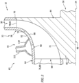
- FIG. 2 illustrates an assembly 62 of the turbine engine 12 along the compressor section 32.
- This engine assembly 62 of FIG. 2 includes the compressor rotor 44 and a portion of the stationary structure 38 and, in particular, an outer shroud 64 (e.g., a tubular flowpath wall) included in the stationary structure 38 along the compressor section 32.
- an outer shroud 64 e.g., a tubular flowpath wall
- the compressor rotor 44 includes a rotor base 66 (e.g., a hub, a disk, etc.) and a plurality of compressor blades 68 (e.g., vanes, airfoil, etc.).
- the rotor base 66 of FIG. 2 projects axially along the axial centerline 24.
- the rotor base 66 projects radially (in a radial outward direction away from the axial centerline 24) to a radial outer side 70 of the compressor rotor 44 and its rotor base 66.
- the rotor base 66 forms a platform with an inner flowpath surface 72.
- This inner flowpath surface 72 may have a curved (e.g., arcuate, quarter circular, splined, etc.) sectional geometry when viewed, for example, in an axial reference plane parallel with (e.g., including) the axial centerline 24.
- the rotor base 66 projects radially (in the radial outward direction) and axially to the inner flowpath surface 72.
- the compressor blades 68 are arranged circumferentially around the axial centerline 24 and the rotor base 66 in an annular array; e.g., a circular array.
- Each of the compressor blades 68 is connected (e.g., formed integral with or mechanically fastened, welded, brazed and/or otherwise attached to) the rotor base 66.
- each compressor blade 68 projects axially out from the rotor base 66 and its inner flowpath surface 72 along the axial centerline 24 to a tip 74 of the respective compressor blade 68 and an axial end 76 of the respective compressor blade 68.
- Each compressor blade 68 projects radially out from the rotor base 66 and its inner flowpath surface 72 (in the radial outward direction) to its blade tip 74 and a radial end 78 of the respective compressor blade 68.
- the blade tip 74 projects radially inwards towards the axial centerline 24 from the blade radial end 78, and the blade tip 74 projects axially along the axial centerline 24 to the blade axial end 76.
- the blade axial end 76 forms a leading edge 80 of the respective compressor blade 68.
- the blade radial end 78 forms a trailing edge 82 of the respective compressor blade 68.
- each compressor blade 68 has a pressure side 84 (e.g., a concave side) and a suction side 86 (e.g., a convex side).
- the compressor rotor 44 is housed within the stationary structure 38 and its shroud 64.
- the shroud 64 for example, is disposed radially and/or axially adjacent the blade tips 74.
- This shroud 64 extends circumferentially around the compressor rotor 44, thereby circumscribing the compressor blades 68 and their blade tips 74.
- the shroud 64 forms an outer flowpath surface 88 opposite the inner flowpath surface 72.
- This outer flowpath surface 88 may have a curved (e.g., arcuate, quarter circular, splined, etc.) sectional geometry when viewed, for example, in the axial reference plane.
- a portion of the core flowpath 30 within the compressor section 32 extends longitudinally across the compressor rotor 44, and is bounded (e.g., radially and/or axially) between the inner flowpath surface 72 and the outer flowpath surface 88.
- the shroud 64 thereby forms an outer flowpath wall along the core flowpath 30 within the compressor section 32.
- the shroud 64 includes one or more ports 90; e.g., through-holes, vents, etc. These ports 90 are arranged circumferentially about the axial centerline 24 in an array; e.g., an arcuate or circular array.
- each port 90 extends (e.g., radially and/or axially) through a thickness of the shroud 64 (e.g., a sidewall of the shroud 64) from an exterior surface 92 of the shroud 64 to the outer flowpath surface 88.
- Each port 90 is thereby fluidly coupled with the core flowpath 30 within the compressor section 32.
- each port 90 of FIG. 2 is arranged longitudinally along the core flowpath 30 at (e.g., on, adjacent or proximate) the compressor rotor 44.
- Each port 90 of FIG. 2 is located longitudinally along the core flowpath 30 downstream of the blade leading edges 80.
- Each port 90 of FIG. 2 is further located longitudinally along the core flowpath 30 upstream of the blade trailing edges 82.
- Each port 90 of FIG. 2 may thereby be positioned longitudinally along the core flowpath 30 between the blade leading edges 80 and the blade trailing edges 82.
- the present disclosure is not limited to such an exemplary arrangement.
- each port 90 may alternatively be aligned with or downstream of the blade trailing edges 82 along the core flowpath 30.
- the electric machine 14 includes an electric machine rotor 94, an electric machine stator 96 and an electric machine housing 98.
- the machine rotor 94 is rotatable about a rotational axis 100 of the machine rotor 94.
- This rotational axis 100 may be an axial centerline of the electric machine 14, and the rotational axis 100 may be parallel (e.g., coaxial) with or offset from the axial centerline 24.
- the machine stator 96 of FIG. 1 is radially outboard of and circumscribes the machine rotor 94. With this arrangement, the electric machine 14 is configured as a radial flux electric machine.
- the electric machine 14 of the present disclosure is not limited to such an exemplary rotor-stator configuration nor to radial flux arrangements.
- the machine rotor 94 may alternatively be radially outboard of and circumscribe the machine stator 96.
- the machine rotor 94 may be axially next to the machine stator 96 configuring the electric machine 14 as an axial flux electric machine.
- the machine rotor 94 and the machine stator 96 are at least partially or completely housed within the machine housing 98.
- the machine rotor 94 is coupled to and rotatable with the rotating assembly 50 through a drivetrain 102.
- This drivetrain 102 may be a direct drive drivetrain where, for example, the machine rotor 94 is coupled to the rotating assembly 50 through a driveshaft. With this arrangement, the machine rotor 94 and the rotating assembly 50 may rotate at a common (the same) rotational velocity.
- the drivetrain 102 may be an indirect drive drivetrain where, for example, an intermediate torque transmission device 104 (or system) couples the machine rotor 94 to the rotating assembly 50. Examples of the torque transmission device 104 include, but are not limited to, a geartrain (e.g., an epicyclic gear system) and a fluid transmission. With this arrangement, the machine rotor 94 and the rotating assembly 50 may rotate at different rotational velocities.
- the electric machine 14 of FIG. 1 may be configurable as an electric generator and/or an electric motor.
- the electric machine 14 may operate as the electric generator to convert mechanical power received from the turbine engine 12 into electricity.
- the rotating assembly 50 and its turbine rotor 46 for example, may drive rotation of the machine rotor 94 through the drivetrain 102.
- the rotation of the machine rotor 94 may generate an electromagnetic field with the machine stator 96, and the machine stator 96 may convert energy from the electromagnetic field into the electricity.
- the electric machine 14 may then provide this electricity to the power source 18 for storage or further use.
- the electric machine 14 may operate as the electric motor to convert electricity received from the power source 18 into mechanical power.
- the machine stator 96 may generate an electromagnetic field with the machine rotor 94 using the electricity. This electromagnetic field may drive rotation of the machine rotor 94. The machine rotor 94 may thereby drive rotation of the rotating assembly 50 through the drivetrain 102. This mechanical power may be provided to initially power the turbine engine 12 during startup.
- the electric machine 14 may alternatively be configured as a dedicated electric generator (e.g., without the electric motor functionality).
- the electric machine 14 of FIG. 1 also includes one or more internal passages 106A-C (generally referred to as "106"). Each of these internal passages 106 is provided to facilitate cooling of the electric machine 14 and one or more of its members 94 and/or 96.
- the internal passages 106 may extend along and/or through one or more of the electric machine members 94 and/or 96.
- the passage 106A (or array of passages about the rotational axis 100), for example, extends (e.g., axially) through a gap (e.g., a radial, clearance gap) between the machine rotor 94 and the machine stator 96.
- the passage 106B (or array of passages about the rotational axis 100) extend (e.g., axially) through the machine stator 96.
- the passage 106C (of array of passages about the rotational axis 100) extend about the machine stator 96; e.g., in a plenum surrounding the machine stator 96 within the machine housing 98.
- These internal passages 106 may collectively form a fluid flowpath 108 (e.g., a cooling flowpath) through the electric machine 14.
- the fluid circuit 16 is configured to fluidly couple the turbine engine 12 to the electric machine 14.
- the fluid circuit 16 of FIG. 1 is configured to fluidly couple the core flowpath 30 to the fluid flowpath 108 and its internal passages 106.
- This fluid circuit 16 includes the ports 90, the fluid flowpath 108 and its internal passages 106, a manifold 110 and a conduit 112; e.g., a pipe, a duct, etc.
- the manifold 110 extends circumferentially about the shroud 64, and fluidly couples the ports 90 to the conduit 112; see also FIGS. 2 and 4 .
- the conduit 112 of FIG. 1 is disposed outside of the turbine engine 12 and the electric machine 14.
- the conduit 112 is between and fluidly couples the ports 90 (e.g., via the manifold 110) to the fluid flowpath 108 and its internal passages 106.
- the fluid circuit 16 may facilitate a fluid transfer between the turbine engine 12 and the electric machine 14 as described below in further detail.
- the power source 18 is electrically coupled with the electric machine 14 through electrical circuitry; e.g., a power bus.
- This electrical circuitry may include one or more electrical leads 114 (e.g., high voltage lines) and one or more electrical devices 116 for conditioning, metering, regulating and/or otherwise controlling electrical power transfer between the electric machine 14 and the power source 18.
- Examples of the electrical devices 116 include, but are not limited to, switches, current regulators, converters and buffers.
- the power source 18 is configured to store electricity.
- the power source 18 is also configured to provide the stored electricity to the electric machine 14 and/or receive electricity from the electric machine 14; e.g., during recharging.
- the power source 18, for example, may be configured as or otherwise include one or more electricity storage devices 118; e.g., batteries, etc.
- the fuel system 20 is configured to deliver the fuel to the turbine engine 12.
- the fuel system 20 of FIG. 5 includes a fuel source 120 and one or more fuel injectors 122.
- the fuel source 120 includes a fuel reservoir 124 and/or a fuel flow regulator 126; e.g., a valve and/or a pump.
- the fuel reservoir 124 is configured to store the fuel before, during and/or after turbine engine operation.
- the fuel reservoir 124 for example, may be configured as or otherwise include a tank, a cylinder, a pressure vessel, a bladder or any other type of fuel storage container.
- the fuel flow regulator 126 is configured to direct and/or meter a flow of the fuel from the fuel reservoir 124 to the fuel injectors 122.
- the fuel injectors 122 may be arranged circumferentially about the axial centerline 24 in an array. Each fuel injector 122 is configured to direct the fuel received from the fuel source 120 into the combustion chamber 56 for mixing with the compressed core air to provide the fuel-air mixture.
- the controller 22 is in signal communication with (e.g., hardwired and/or wirelessly coupled to) one or more members of the powerplant 10; e.g., elements 14, 20 and 116.
- the controller 22 may be implemented with a combination of hardware and software.
- the hardware may include at least one processing device 128 and memory 130.
- the processing device 128 may include one or more single-core and/or multi-core processors.
- the hardware may also or alternatively include analog and/or digital circuitry other than that described above.
- the memory 130 is configured to store software (e.g., program instructions) for execution by the processing device 128, which software execution may control and/or facilitate performance of one or more operations such as those described herein.
- the memory 130 may be a non-transitory computer readable medium.
- the memory 130 may be configured as or include a volatile memory and/or a nonvolatile memory.
- a volatile memory may include a random access memory (RAM) such as a dynamic random access memory (DRAM), a static random access memory (SRAM), a synchronous dynamic random access memory (SDRAM), a video random access memory (VRAM), etc.
- RAM random access memory
- DRAM dynamic random access memory
- SRAM static random access memory
- SDRAM synchronous dynamic random access memory
- VRAM video random access memory
- Examples of a nonvolatile memory may include a read only memory (ROM), an electrically erasable programmable read-only memory (EEPROM), a computer hard drive, etc.
- ROM read only memory
- EEPROM electrically erasable programmable read-only memory
- FIG. 6 is a flow diagram of a method 600 of operation for a powerplant.
- the operating method 600 is described below with respect to the powerplant 10 described above.
- the operating method 600 of the present disclosure is not limited to such an exemplary powerplant.
- step 602 the powerplant 10 is operated to startup the turbine engine 12.
- the controller 22 may signal the electrical devices 116 to direct electricity from the power source 18 to the electric machine 14 to facilitate electric motor operation.
- the electricity powers rotation of the machine rotor 94 as discussed above, and the machine rotor 94 may drive rotation of the rotating assembly 50 through the drivetrain 102.
- the controller 22 may signal the fuel system 20 to deliver fuel to the turbine engine 12 and its fuel injectors 122.
- the fuel injectors 122 may inject the fuel into the combustion chamber 56 for mixing with air compressed by the electric machine driven rotating assembly 50 and its compressor rotor 44.
- This fuel-air mixture may be ignited and combustion products thereof may flow out of the combustor section 33, through the turbine section 34 and the exhaust section 35, and out of the turbine engine 12 through the core exhaust 42.
- the rotating assembly 50 spools up and as combustion of the fuel-air mixture within the combustion chamber 56 becomes self-sustaining, the flow of electricity to the electric machine 14 may be decreased and/or stopped.
- the turbine engine 12 may then be powered up (e.g., fed more fuel by the fuel system 20) for regular turbine engine operation.
- air may be vented out of the core flowpath 30 through the ports 90 in the shroud 64. Such venting may reduce or prevent occurrence of surge and/or various other undesirable modes within the turbine engine 12 and, for example, its compressor section 32.
- the air vented from the compressor section 32 through the ports 90 is directed through the fluid circuit 16 to the electric machine 14.
- This air may then flow through the fluid flowpath 108 and its internal passages 106 before being exhausted from the electric machine 14, for example, via an orifice 132 (or orifices); here, a fluid circuit exhaust.
- the air may cool one or more members 94 and/or 96 of the electric machine 14.
- the fluid circuit 16 may thereby facilitate cooling of the electric machine 14 during the engine startup operation.
- step 604 the powerplant 10 is operated to facilitate regular operation of the turbine engine 12, for example, as described above.
- air may now be drawn (e.g., suctioned via vacuum) into the core flowpath 30 through the ports 90.
- the compressor section 32 may thereby draw air into the fluid circuit 16 through the orifice 132 (or orifices); here, a fluid circuit inlet.
- This air flows through the fluid flowpath 108 and its internal passages 106, where the air may further cool one or more members 94 and/or 96 of the electric machine 14.
- the fluid circuit 16 may thereby facilitate cooling of the electric machine 14 during the regular engine operation.
- the air may then flow through the conduit 112, the manifold 110 and the ports 90 into the core flowpath 30, where that air may be compressed by the compressor rotor 44 and directed into the combustor section 33, with the air received through the core inlet 40, as the core air. It is contemplated the air drawn into the core flowpath 30 through the fluid circuit 16 and its ports 90 may account for about one percent (1%) to two percent (2%) of the core air delivered to the combustor section 33 during the regular engine operation. The present disclosure, however, is not limited to such an exemplary relationship.
- the compressed core air may be bled from the diffuser plenum 60 and directed through at least one valve 134 to the one or more other devices.
- the valve 134 may be closed during the engine startup operation described above.
- the turbine engine 12 may power operation of the electric machine 14 as the electric generator.
- the rotating assembly 50 for example, may drive rotation of the machine rotor 94 through the drivetrain 102. This rotation of the machine rotor 94 may facilitate generation of electricity as described above, and the electricity may be provided to the power source 18 for storage or distribution to other aircraft electronics.
- the compressor rotor 44 is described above as a radial flow compressor rotor. It is contemplated, however, the shroud 64 and its port(s) 90 may alternatively be arranged along an axial flow compressor rotor in other embodiments.
Landscapes
- Engineering & Computer Science (AREA)
- Chemical & Material Sciences (AREA)
- Combustion & Propulsion (AREA)
- Mechanical Engineering (AREA)
- General Engineering & Computer Science (AREA)
- Power Engineering (AREA)
- Structures Of Non-Positive Displacement Pumps (AREA)
Abstract
A powerplant (10) is provided that includes an electric machine (14), a turbine engine (12) and a fluid circuit (16). The turbine engine (12) is operatively coupled to the electric machine (14). The turbine engine (12) includes a flowpath (30), a compressor section (32), a combustor section (33) and a turbine section (34). The flowpath (30) extends through the compressor section (32), the combustor section (33) and the turbine section (34) from an inlet (40) into the flowpath (30) to an exhaust (42) from the flowpath (30). The compressor section (32) includes a shroud (64) forming a peripheral boundary of the flowpath (30). The fluid circuit (16) includes a passage (106A, 106B, 106C), a port (90) and a conduit (112). The passage (106A, 106B, 106C) is within the electric machine (14). The port (90) extends through the shroud (64) to the flowpath (30). The conduit (112) fluidly couples the passage (106A, 106B, 106C) to the port (90).
Description
- This disclosure relates generally to a powerplant and, more particularly, to cooling an electric machine of the powerplant.
- A powerplant such as an auxiliary power unit (APU) for an aircraft typically includes an electric motor mechanically driven by an auxiliary power unit engine. The electric motor may generate heat during operation which needs to be dissipated. Various systems and methods are known in the art for cooling an electric motor. While these known cooling systems and methods have various benefits, there is still room in the art for improvement.
- According to an aspect of the present disclosure, a powerplant is provided that includes an electric machine, a turbine engine and a fluid circuit. The turbine engine is operatively coupled to the electric machine. The turbine engine includes a flowpath, a compressor section, a combustor section and a turbine section. The flowpath extends through the compressor section, the combustor section and the turbine section from an inlet into the flowpath to an exhaust from the flowpath. The compressor section includes a shroud forming a peripheral boundary of the flowpath. The fluid circuit includes a passage, a port and a conduit. The passage is within the electric machine. The port extends through the shroud to the flowpath. The conduit fluidly couples the passage to the port.
- According to another aspect of the present disclosure, another powerplant is provided that includes an electric machine and a turbine engine. The electric machine includes an internal passage. The turbine engine is operatively coupled to the electric machine. The turbine engine includes a flowpath, a compressor section, a combustor section and a turbine section. The flowpath extends through the compressor section, the combustor section and the turbine section from an inlet into the flowpath to an exhaust from the flowpath. The turbine engine is configured to draw air through the internal passage and into the core flowpath during operation.
- According to still another aspect of the present disclosure, a method of operation is provided. This method includes: driving rotation of a rotor within an electric machine using a turbine engine to generate electricity; and drawing air through an internal passage of the electric machine into a flowpath of the turbine engine to cool the electric machine.
- The following optional features may be applied to any of the above aspects.
- The internal passage may be fluidly coupled to the flowpath through a port in a shroud housing a compressor rotor of the turbine engine.
- The turbine engine may include a compressor section, a combustor section and a turbine section. The flowpath may extend through the compressor section, the combustor section and the turbine section from an inlet into the flowpath to an exhaust from the flowpath.
- The electric machine may include an electric machine stator. The passage may extend through and/or along the electric machine stator.
- The electric machine may include an electric machine rotor. The passage may extend through and/or along the electric machine rotor.
- The compressor section may also include a compressor rotor housed within the shroud. The compressor rotor may include a plurality of compressor blades arranged circumferentially about an axis and disposed within the flowpath.
- The port may be located longitudinally along the flowpath at the compressor rotor.
- The compressor blades may include a first compressor blade. The port may be located longitudinally along the flowpath downstream of a leading edge of the first compressor blade.
- The compressor blades may include a first compressor blade. The port may be located longitudinally along the flowpath upstream of a trailing edge of the first compressor blade.
- The compressor blades may include a first compressor blade. The port may be located longitudinally along the flowpath between a leading edge of the first compressor blade and a trailing edge of the first compressor blade.
- The compressor rotor may be configured as a radial flow compressor rotor.
- The port may be a first port, and the fluid circuit may also include a second port and a manifold. The second port may extend through the shroud to the flowpath. The manifold may fluidly couple the first port and the second port to the conduit.
- The compressor section may be configured to draw air through the fluid circuit and into the flowpath during regular operation of the turbine engine.
- The compressor section may be configured to direct air out the flowpath and into the fluid circuit during startup operation of the turbine engine.
- The electric machine may be configurable as an electric generator.
- The electric machine may be configurable as an electric motor.
- The powerplant may also include a drivetrain rotatably coupling a rotating assembly of the turbine engine to a rotor of the electric machine.
- The drivetrain may include a geartrain coupled between the rotating assembly of the turbine engine and the rotor of the electric machine.
- The present disclosure may include any one or more of the individual features disclosed above and/or below alone or in any combination thereof.
- The foregoing features and the operation of the invention will become more apparent in light of the following description and the accompanying drawings.
-
-
FIG. 1 is a partial schematic illustration of a powerplant for an aircraft. -
FIG. 2 is a partial sectional illustration of an assembly of the aircraft powerplant along a compressor section. -
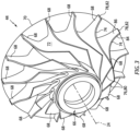
FIG. 3 is a perspective illustration of a compressor rotor. -
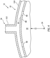
FIG. 4 is a partial cross-sectional illustration of a stationary structure in the compressor section. -
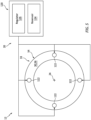
FIG. 5 is a schematic illustration of a fuel system for a combustor section. -
FIG. 6 is a flow diagram of a method of operation for an aircraft powerplant. -
FIG. 1 illustrates apowerplant 10 for an aircraft. The aircraft may be an airplane, a helicopter, a drone (e.g., an unmanned aerial vehicle (UAV)) or any other manned or unmanned aerial vehicle or system. For ease of description, thepowerplant 10 may be generally described below as an auxiliary power unit (APU) for the aircraft. However, it is contemplated thepowerplant 10 may also or alternatively be configured as part of a propulsion system for the aircraft. It is further contemplated thepowerplant 10 may alternatively be configured for a non-aircraft application such as, for example, a ground-based power generation system or otherwise. - The
powerplant 10 ofFIG. 1 includes agas turbine engine 12, anelectric machine 14 and afluid circuit 16; e.g., a cooling circuit for theelectric machine 14. Thepowerplant 10 ofFIG. 1 also includes apower source 18, afuel system 20 and acontroller 22 for controlling operation of thepowerplant 10. - The
turbine engine 12 ofFIG. 1 extends axially along anaxial centerline 24 from a forward, upstream airflow inlet 26 into theturbine engine 12 to an aft, downstream combustion products exhaust 28 from theturbine engine 12. Thisaxial centerline 24 may be a centerline axis and/or a rotational axis of theturbine engine 12 and/or one or more components within theturbine engine 12. - The
turbine engine 12 ofFIG. 1 includes acore flowpath 30, aninlet section 31, acompressor section 32, a (e.g., reverse flow)combustor section 33, aturbine section 34 and anexhaust section 35. At least (or only) thecompressor section 32, thecombustor section 33 and theturbine section 34 may form a core of theturbine engine 12. Theturbine engine 12 also includes astationary structure 38 housing and/or forming one or more or all of the engine sections 31-35. - The
core flowpath 30 extends within theturbine engine 12 and its engine core from an airflow inlet 40 to thecore flowpath 30 to a combustion products exhaust 42 from thecore flowpath 30. More particularly, thecore flowpath 30 ofFIG. 1 extends sequentially through theinlet section 31, thecompressor section 32, thecombustor section 33 and theturbine section 34 to theexhaust section 35. The core inlet 40 may form the engine inlet 26 into theturbine engine 12. The core exhaust 42 may form the engine exhaust 28 from theturbine engine 12. - The
compressor section 32 includes abladed compressor rotor 44. Theturbine section 34 includes a bladedturbine rotor 46. Thecompressor rotor 44 may be configured as a radial flow compressor rotor (e.g., an axial inflow-radial outflow compressor rotor), and thecompressor section 32 may be configured as a radial flow compressor section. Theturbine rotor 46 may be configured as a radial flow turbine rotor (e.g., a radial inflow-axial outflow turbine rotor), and theturbine section 34 may be configured as a radial flow turbine section. Thecompressor rotor 44 is connected to theturbine rotor 46 through anengine shaft 48. At least (or only) thecompressor rotor 44, theturbine rotor 46 and theengine shaft 48 may collectively form an engine rotating assembly 50 (e.g., a spool) of theturbine engine 12. This rotatingassembly 50 and itsengine shaft 48 are rotatably supported by thestationary structure 38 through one or more bearings 52 (one shown for ease of illustration); e.g., rolling element bearings, journal bearings, etc. - The
combustor section 33 includes a combustor 54 (e.g., an annular combustor) with an internal combustion chamber 56 (e.g., an annular combustion chamber). Thecombustor 54 ofFIG. 1 is configured as a reverse flow combustor.Inlet ports 58 / flow tubes into the combustion chamber 56, for example, may be arranged at (e.g., on, adjacent or proximate) and/or towards an aft bulkhead wall of thecombustor 54. An outlet from thecombustor 54 may be arranged axially aft of an inlet to theturbine section 34. Thecombustor 54 may also be arranged radially outboard of and/or axially overlap at least a (e.g., aft) portion of theturbine section 34. With this arrangement, thecore flowpath 30 ofFIG. 1 reverses direction (e.g., from a forward-to-aft direction to an aft-to-forward direction) a first time as thecore flowpath 30 extends from adiffuser plenum 60 surrounding thecombustor 54 into the combustion chamber 56. The core flowpath 30 ofFIG. 1 then reverses direction (e.g., from the aft-to-forward direction to the forward-to-aft direction) a second time as thecore flowpath 30 extends from the combustion chamber 56 into theturbine section 34. - During regular operation of the
turbine engine 12, air enters theturbine engine 12 through theinlet section 31 and its core inlet 40. Theinlet section 31 directs the air from the core inlet 40 into thecore flowpath 30 and thecompressor section 32. The air entering thecore flowpath 30 may be referred to as "core air". This core air is compressed by thecompressor rotor 44. The compressed core air is directed through a diffuser and itsdiffuser plenum 60 into the combustion chamber 56. Fuel is injected and mixed with the compressed core air to provide a fuel-air mixture. This fuel-air mixture is ignited within the combustion chamber 56, and combustion products thereof flow through theturbine section 34 and cause theturbine rotor 46 to rotate. The rotation of theturbine rotor 46 drives rotation of thecompressor rotor 44 and, thus, compression of the air received from the core inlet 40. -
FIG. 2 illustrates anassembly 62 of theturbine engine 12 along thecompressor section 32. Thisengine assembly 62 ofFIG. 2 includes thecompressor rotor 44 and a portion of thestationary structure 38 and, in particular, an outer shroud 64 (e.g., a tubular flowpath wall) included in thestationary structure 38 along thecompressor section 32. - The
compressor rotor 44 includes a rotor base 66 (e.g., a hub, a disk, etc.) and a plurality of compressor blades 68 (e.g., vanes, airfoil, etc.). Therotor base 66 ofFIG. 2 projects axially along theaxial centerline 24. Therotor base 66 projects radially (in a radial outward direction away from the axial centerline 24) to a radialouter side 70 of thecompressor rotor 44 and itsrotor base 66. Therotor base 66 forms a platform with aninner flowpath surface 72. Thisinner flowpath surface 72 may have a curved (e.g., arcuate, quarter circular, splined, etc.) sectional geometry when viewed, for example, in an axial reference plane parallel with (e.g., including) theaxial centerline 24. With this arrangement, therotor base 66 projects radially (in the radial outward direction) and axially to theinner flowpath surface 72. - Referring to
FIG. 3 , thecompressor blades 68 are arranged circumferentially around theaxial centerline 24 and therotor base 66 in an annular array; e.g., a circular array. Each of thecompressor blades 68 is connected (e.g., formed integral with or mechanically fastened, welded, brazed and/or otherwise attached to) therotor base 66. Referring toFIG. 2 , eachcompressor blade 68 projects axially out from therotor base 66 and itsinner flowpath surface 72 along theaxial centerline 24 to atip 74 of therespective compressor blade 68 and an axial end 76 of therespective compressor blade 68. Eachcompressor blade 68 projects radially out from therotor base 66 and its inner flowpath surface 72 (in the radial outward direction) to itsblade tip 74 and a radial end 78 of therespective compressor blade 68. Theblade tip 74 projects radially inwards towards theaxial centerline 24 from the blade radial end 78, and theblade tip 74 projects axially along theaxial centerline 24 to the blade axial end 76. The blade axial end 76 forms a leading edge 80 of therespective compressor blade 68. The blade radial end 78 forms a trailing edge 82 of therespective compressor blade 68. Referring toFIG. 3 , eachcompressor blade 68 has a pressure side 84 (e.g., a concave side) and a suction side 86 (e.g., a convex side). - Referring again to
FIG. 2 , thecompressor rotor 44 is housed within thestationary structure 38 and itsshroud 64. Theshroud 64, for example, is disposed radially and/or axially adjacent theblade tips 74. Thisshroud 64 extends circumferentially around thecompressor rotor 44, thereby circumscribing thecompressor blades 68 and theirblade tips 74. Theshroud 64 forms anouter flowpath surface 88 opposite theinner flowpath surface 72. This outerflowpath surface 88 may have a curved (e.g., arcuate, quarter circular, splined, etc.) sectional geometry when viewed, for example, in the axial reference plane. With this arrangement, a portion of thecore flowpath 30 within thecompressor section 32 extends longitudinally across thecompressor rotor 44, and is bounded (e.g., radially and/or axially) between theinner flowpath surface 72 and theouter flowpath surface 88. Theshroud 64 thereby forms an outer flowpath wall along thecore flowpath 30 within thecompressor section 32. - Referring to
FIG. 4 , theshroud 64 includes one ormore ports 90; e.g., through-holes, vents, etc. Theseports 90 are arranged circumferentially about theaxial centerline 24 in an array; e.g., an arcuate or circular array. Referring toFIG. 2 , eachport 90 extends (e.g., radially and/or axially) through a thickness of the shroud 64 (e.g., a sidewall of the shroud 64) from anexterior surface 92 of theshroud 64 to theouter flowpath surface 88. Eachport 90 is thereby fluidly coupled with thecore flowpath 30 within thecompressor section 32. Eachport 90 ofFIG. 2 is arranged longitudinally along thecore flowpath 30 at (e.g., on, adjacent or proximate) thecompressor rotor 44. Eachport 90 ofFIG. 2 , for example, is located longitudinally along thecore flowpath 30 downstream of the blade leading edges 80. Eachport 90 ofFIG. 2 is further located longitudinally along thecore flowpath 30 upstream of the blade trailing edges 82. Eachport 90 ofFIG. 2 may thereby be positioned longitudinally along thecore flowpath 30 between the blade leading edges 80 and the blade trailing edges 82. The present disclosure, however, is not limited to such an exemplary arrangement. For example, in other embodiments, eachport 90 may alternatively be aligned with or downstream of the blade trailing edges 82 along thecore flowpath 30. - Referring to
FIG. 1 , theelectric machine 14 includes anelectric machine rotor 94, anelectric machine stator 96 and anelectric machine housing 98. Themachine rotor 94 is rotatable about arotational axis 100 of themachine rotor 94. Thisrotational axis 100 may be an axial centerline of theelectric machine 14, and therotational axis 100 may be parallel (e.g., coaxial) with or offset from theaxial centerline 24. Themachine stator 96 ofFIG. 1 is radially outboard of and circumscribes themachine rotor 94. With this arrangement, theelectric machine 14 is configured as a radial flux electric machine. Theelectric machine 14 of the present disclosure, however, is not limited to such an exemplary rotor-stator configuration nor to radial flux arrangements. Themachine rotor 94, for example, may alternatively be radially outboard of and circumscribe themachine stator 96. In another example, themachine rotor 94 may be axially next to themachine stator 96 configuring theelectric machine 14 as an axial flux electric machine. Referring again toFIG. 1 , themachine rotor 94 and themachine stator 96 are at least partially or completely housed within themachine housing 98. - The
machine rotor 94 is coupled to and rotatable with the rotatingassembly 50 through adrivetrain 102. Thisdrivetrain 102 may be a direct drive drivetrain where, for example, themachine rotor 94 is coupled to the rotatingassembly 50 through a driveshaft. With this arrangement, themachine rotor 94 and the rotatingassembly 50 may rotate at a common (the same) rotational velocity. Alternatively, thedrivetrain 102 may be an indirect drive drivetrain where, for example, an intermediate torque transmission device 104 (or system) couples themachine rotor 94 to the rotatingassembly 50. Examples of thetorque transmission device 104 include, but are not limited to, a geartrain (e.g., an epicyclic gear system) and a fluid transmission. With this arrangement, themachine rotor 94 and the rotatingassembly 50 may rotate at different rotational velocities. - The
electric machine 14 ofFIG. 1 may be configurable as an electric generator and/or an electric motor. For example, during a generator mode of operation, theelectric machine 14 may operate as the electric generator to convert mechanical power received from theturbine engine 12 into electricity. The rotatingassembly 50 and itsturbine rotor 46, for example, may drive rotation of themachine rotor 94 through thedrivetrain 102. The rotation of themachine rotor 94 may generate an electromagnetic field with themachine stator 96, and themachine stator 96 may convert energy from the electromagnetic field into the electricity. Theelectric machine 14 may then provide this electricity to thepower source 18 for storage or further use. During a motor mode of operation, theelectric machine 14 may operate as the electric motor to convert electricity received from thepower source 18 into mechanical power. Themachine stator 96, for example, may generate an electromagnetic field with themachine rotor 94 using the electricity. This electromagnetic field may drive rotation of themachine rotor 94. Themachine rotor 94 may thereby drive rotation of the rotatingassembly 50 through thedrivetrain 102. This mechanical power may be provided to initially power theturbine engine 12 during startup. Of course, in other embodiments, theelectric machine 14 may alternatively be configured as a dedicated electric generator (e.g., without the electric motor functionality). - The
electric machine 14 ofFIG. 1 also includes one or moreinternal passages 106A-C (generally referred to as "106"). Each of these internal passages 106 is provided to facilitate cooling of theelectric machine 14 and one or more of itsmembers 94 and/or 96. The internal passages 106, for example, may extend along and/or through one or more of theelectric machine members 94 and/or 96. Thepassage 106A (or array of passages about the rotational axis 100), for example, extends (e.g., axially) through a gap (e.g., a radial, clearance gap) between themachine rotor 94 and themachine stator 96. Thepassage 106B (or array of passages about the rotational axis 100) extend (e.g., axially) through themachine stator 96. Thepassage 106C (of array of passages about the rotational axis 100) extend about themachine stator 96; e.g., in a plenum surrounding themachine stator 96 within themachine housing 98. These internal passages 106 may collectively form a fluid flowpath 108 (e.g., a cooling flowpath) through theelectric machine 14. - The
fluid circuit 16 is configured to fluidly couple theturbine engine 12 to theelectric machine 14. Thefluid circuit 16 ofFIG. 1 , for example, is configured to fluidly couple thecore flowpath 30 to thefluid flowpath 108 and its internal passages 106. Thisfluid circuit 16 includes theports 90, thefluid flowpath 108 and its internal passages 106, a manifold 110 and aconduit 112; e.g., a pipe, a duct, etc. The manifold 110 extends circumferentially about theshroud 64, and fluidly couples theports 90 to theconduit 112; see alsoFIGS. 2 and4 . Theconduit 112 ofFIG. 1 is disposed outside of theturbine engine 12 and theelectric machine 14. Theconduit 112 is between and fluidly couples the ports 90 (e.g., via the manifold 110) to thefluid flowpath 108 and its internal passages 106. With this arrangement, thefluid circuit 16 may facilitate a fluid transfer between theturbine engine 12 and theelectric machine 14 as described below in further detail. - The
power source 18 is electrically coupled with theelectric machine 14 through electrical circuitry; e.g., a power bus. This electrical circuitry may include one or more electrical leads 114 (e.g., high voltage lines) and one or moreelectrical devices 116 for conditioning, metering, regulating and/or otherwise controlling electrical power transfer between theelectric machine 14 and thepower source 18. Examples of theelectrical devices 116 include, but are not limited to, switches, current regulators, converters and buffers. - The
power source 18 is configured to store electricity. Thepower source 18 is also configured to provide the stored electricity to theelectric machine 14 and/or receive electricity from theelectric machine 14; e.g., during recharging. Thepower source 18, for example, may be configured as or otherwise include one or moreelectricity storage devices 118; e.g., batteries, etc. - Referring to
FIG. 5 , thefuel system 20 is configured to deliver the fuel to theturbine engine 12. Thefuel system 20 ofFIG. 5 includes afuel source 120 and one ormore fuel injectors 122. Thefuel source 120 includes afuel reservoir 124 and/or afuel flow regulator 126; e.g., a valve and/or a pump. Thefuel reservoir 124 is configured to store the fuel before, during and/or after turbine engine operation. Thefuel reservoir 124, for example, may be configured as or otherwise include a tank, a cylinder, a pressure vessel, a bladder or any other type of fuel storage container. Thefuel flow regulator 126 is configured to direct and/or meter a flow of the fuel from thefuel reservoir 124 to thefuel injectors 122. Thefuel injectors 122 may be arranged circumferentially about theaxial centerline 24 in an array. Eachfuel injector 122 is configured to direct the fuel received from thefuel source 120 into the combustion chamber 56 for mixing with the compressed core air to provide the fuel-air mixture. - Referring to
FIG. 1 , thecontroller 22 is in signal communication with (e.g., hardwired and/or wirelessly coupled to) one or more members of thepowerplant 10; e.g.,elements controller 22 may be implemented with a combination of hardware and software. The hardware may include at least oneprocessing device 128 andmemory 130. Theprocessing device 128 may include one or more single-core and/or multi-core processors. The hardware may also or alternatively include analog and/or digital circuitry other than that described above. Thememory 130 is configured to store software (e.g., program instructions) for execution by theprocessing device 128, which software execution may control and/or facilitate performance of one or more operations such as those described herein. Thememory 130 may be a non-transitory computer readable medium. For example, thememory 130 may be configured as or include a volatile memory and/or a nonvolatile memory. Examples of a volatile memory may include a random access memory (RAM) such as a dynamic random access memory (DRAM), a static random access memory (SRAM), a synchronous dynamic random access memory (SDRAM), a video random access memory (VRAM), etc. Examples of a nonvolatile memory may include a read only memory (ROM), an electrically erasable programmable read-only memory (EEPROM), a computer hard drive, etc. -
FIG. 6 is a flow diagram of amethod 600 of operation for a powerplant. For ease of description, theoperating method 600 is described below with respect to thepowerplant 10 described above. Theoperating method 600 of the present disclosure, however, is not limited to such an exemplary powerplant. - In
step 602, thepowerplant 10 is operated to startup theturbine engine 12. During this engine startup operation, thecontroller 22 may signal theelectrical devices 116 to direct electricity from thepower source 18 to theelectric machine 14 to facilitate electric motor operation. The electricity powers rotation of themachine rotor 94 as discussed above, and themachine rotor 94 may drive rotation of the rotatingassembly 50 through thedrivetrain 102. Concurrently or subsequently, thecontroller 22 may signal thefuel system 20 to deliver fuel to theturbine engine 12 and itsfuel injectors 122. Thefuel injectors 122 may inject the fuel into the combustion chamber 56 for mixing with air compressed by the electric machine driven rotatingassembly 50 and itscompressor rotor 44. This fuel-air mixture may be ignited and combustion products thereof may flow out of thecombustor section 33, through theturbine section 34 and theexhaust section 35, and out of theturbine engine 12 through the core exhaust 42. As the rotatingassembly 50 spools up and as combustion of the fuel-air mixture within the combustion chamber 56 becomes self-sustaining, the flow of electricity to theelectric machine 14 may be decreased and/or stopped. Theturbine engine 12 may then be powered up (e.g., fed more fuel by the fuel system 20) for regular turbine engine operation. - During the engine startup operation, air may be vented out of the
core flowpath 30 through theports 90 in theshroud 64. Such venting may reduce or prevent occurrence of surge and/or various other undesirable modes within theturbine engine 12 and, for example, itscompressor section 32. The air vented from thecompressor section 32 through theports 90 is directed through thefluid circuit 16 to theelectric machine 14. This air may then flow through thefluid flowpath 108 and its internal passages 106 before being exhausted from theelectric machine 14, for example, via an orifice 132 (or orifices); here, a fluid circuit exhaust. As the air flows through the internal passages 106, the air may cool one ormore members 94 and/or 96 of theelectric machine 14. Thefluid circuit 16 may thereby facilitate cooling of theelectric machine 14 during the engine startup operation. - In
step 604, thepowerplant 10 is operated to facilitate regular operation of theturbine engine 12, for example, as described above. During this regular engine operation, air may now be drawn (e.g., suctioned via vacuum) into thecore flowpath 30 through theports 90. Thecompressor section 32 may thereby draw air into thefluid circuit 16 through the orifice 132 (or orifices); here, a fluid circuit inlet. This air flows through thefluid flowpath 108 and its internal passages 106, where the air may further cool one ormore members 94 and/or 96 of theelectric machine 14. Thefluid circuit 16 may thereby facilitate cooling of theelectric machine 14 during the regular engine operation. The air may then flow through theconduit 112, the manifold 110 and theports 90 into thecore flowpath 30, where that air may be compressed by thecompressor rotor 44 and directed into thecombustor section 33, with the air received through the core inlet 40, as the core air. It is contemplated the air drawn into thecore flowpath 30 through thefluid circuit 16 and itsports 90 may account for about one percent (1%) to two percent (2%) of the core air delivered to thecombustor section 33 during the regular engine operation. The present disclosure, however, is not limited to such an exemplary relationship. - While the air is drawing into the
core flowpath 30 through theports 90, some of the compressed core air may also be bled from thecore flowpath 30. This bleed air may be provided to one or more other devices outside of theturbine engine 12 and/or thepowerplant 10; e.g., a propulsion engine starter motor, an actuator, an aircraft environmental control system, etc. The compressed core air, for example, may be bled from thediffuser plenum 60 and directed through at least onevalve 134 to the one or more other devices. Thevalve 134, however, may be closed during the engine startup operation described above. - During the regular engine operation, the
turbine engine 12 may power operation of theelectric machine 14 as the electric generator. The rotatingassembly 50, for example, may drive rotation of themachine rotor 94 through thedrivetrain 102. This rotation of themachine rotor 94 may facilitate generation of electricity as described above, and the electricity may be provided to thepower source 18 for storage or distribution to other aircraft electronics. - The
compressor rotor 44 is described above as a radial flow compressor rotor. It is contemplated, however, theshroud 64 and its port(s) 90 may alternatively be arranged along an axial flow compressor rotor in other embodiments. - While various embodiments of the present disclosure have been described, it will be apparent to those of ordinary skill in the art that many more embodiments and implementations are possible within the scope of the disclosure. For example, the present disclosure as described herein includes several aspects and embodiments that include particular features. Although these features may be described individually, it is within the scope of the present disclosure that some or all of these features may be combined with any one of the aspects and remain within the scope of the disclosure. Accordingly, the present disclosure is not to be restricted except in light of the attached claims and their equivalents.
Claims (15)
- A powerplant (10), comprising:an electric machine (14);a turbine engine (12) operatively coupled to the electric machine (14), the turbine engine (12) including a flowpath (30), a compressor section (32), a combustor section (33) and a turbine section (34), the flowpath (30) extending through the compressor section (32), the combustor section (33) and the turbine section (34) from an inlet (40) into the flowpath (30) to an exhaust (42) from the flowpath (30), and the compressor section (32) comprising a shroud (64) forming a peripheral boundary of the flowpath (30); anda fluid circuit (16) including:a passage (106A, 106B, 106C) within the electric machine (14);a port (90) extending through the shroud (64) to the flowpath (30); anda conduit (112) fluidly coupling the passage (106A, 106B, 106C) to the port (90).
- The powerplant (10) of claim 1, wherein:the electric machine (14) comprises an electric machine stator (96); andthe passage (106A, 106B, 106C) extends at least one of through or along the electric machine stator (96).
- The powerplant (10) of claim 1 or 2, wherein:the electric machine (14) comprises an electric machine rotor (94); andthe passage (106A, 106B, 106C) extends at least one of through or along the electric machine rotor (94).
- The powerplant (10) of claim 1, 2 or 3, wherein:the compressor section (32) further comprises a compressor rotor (44) housed within the shroud (64);the compressor rotor (44) including a plurality of compressor blades (68) arranged circumferentially about an axis (24) and disposed within the flowpath (30),wherein, optionally, the compressor rotor (44) is configured as a radial flow compressor rotor.
- The powerplant (10) of claim 4, wherein the port (90) is located longitudinally along the flowpath (30) at the compressor rotor (44).
- The powerplant (10) of claim 4 or 5, wherein:the plurality of compressor blades (68) include a first compressor blade; andthe port (90) is located longitudinally along the flowpath (30) downstream of a leading edge (80) of the first compressor blade.
- The powerplant (10) of claim 4, 5 or 6, wherein:the plurality of compressor blades (68) include a first compressor blade; andthe port (90) is located longitudinally along the flowpath (30) upstream of a trailing edge (82) of the first compressor blade.
- The powerplant (10) of any of claims 4 to 7, wherein:the plurality of compressor blades (68) include a first compressor blade; andthe port (90) is located longitudinally along the flowpath (30) between a leading edge (80) of the first compressor blade and a trailing edge (82) of the first compressor blade.
- The powerplant (10) of any preceding claim, wherein:the port (90) is a first port, and the fluid circuit (16) further includes a second port (90) and a manifold (110);the second port (90) extends through the shroud (64) to the flowpath (30); andthe manifold (110) fluidly couples the first port (90) and the second port (90) to the conduit (112).
- The powerplant (10) of any preceding claim, wherein:the compressor section (32) is configured to draw air through the fluid circuit (16) and into the flowpath (30) during regular operation of the turbine engine (12); and/orthe compressor section (32) is configured to direct air out the flowpath (30) and into the fluid circuit (16) during startup operation of the turbine engine (12).
- The powerplant (10) of any preceding claim, wherein:the electric machine (14) is configurable as an electric generator; and/orthe electric machine (14) is configurable as an electric motor.
- The powerplant (10) of any preceding claim, further comprising a drivetrain (102) rotatably coupling a rotating assembly (50) of the turbine engine (12) to a rotor (94) of the electric machine (14),
wherein, optionally, the drivetrain (102) comprises a geartrain coupled between the rotating assembly (50) of the turbine engine (12) and the rotor (94) of the electric machine (14). - A powerplant (10), comprising:an electric machine (14) comprising an internal passage (106A, 106B, 106C); anda turbine engine (12) operatively coupled to the electric machine (14), the turbine engine (12) including a flowpath (30), a compressor section (32), a combustor section (33) and a turbine section (34);the flowpath (30) extending through the compressor section (32), the combustor section (33) and the turbine section (34) from an inlet (40) into the flowpath (30) to an exhaust (42) from the flowpath (30); andthe turbine engine (12) configured to draw air through the internal passage (106A, 106B, 106C) and into the core flowpath (30) during operation.
- A method of operation, comprising:driving rotation of a rotor (94) within an electric machine (14) using a turbine engine (12) to generate electricity; anddrawing air through an internal passage (106A, 106B, 106C) of the electric machine (14) into a flowpath (30) of the turbine engine (12) to cool the electric machine (14).
- The method of claim 14, wherein:the internal passage (106A, 106B, 106C) is fluidly coupled to the flowpath (30) through a port (90) in a shroud (64) housing a compressor rotor (44) of the turbine engine (12); and/orthe turbine engine (12) includes a compressor section (32), a combustor section (33) and a turbine section (34), and the flowpath (30) extends through the compressor section (32), the combustor section (33) and the turbine section (34) from an inlet (40) into the flowpath (30) to an exhaust (42) from the flowpath (30).
Applications Claiming Priority (1)
| Application Number | Priority Date | Filing Date | Title |
|---|---|---|---|
| US18/217,241 US12525841B2 (en) | 2023-06-30 | 2023-06-30 | Cooling an electric machine of a turbine engine powerplant |
Publications (1)
| Publication Number | Publication Date |
|---|---|
| EP4484714A1 true EP4484714A1 (en) | 2025-01-01 |
Family
ID=91759461
Family Applications (1)
| Application Number | Title | Priority Date | Filing Date |
|---|---|---|---|
| EP24185766.3A Pending EP4484714A1 (en) | 2023-06-30 | 2024-07-01 | Cooling an electric machine of a gas turbine engine powerplant |
Country Status (2)
| Country | Link |
|---|---|
| US (1) | US12525841B2 (en) |
| EP (1) | EP4484714A1 (en) |
Citations (4)
| Publication number | Priority date | Publication date | Assignee | Title |
|---|---|---|---|---|
| US5449961A (en) * | 1993-03-18 | 1995-09-12 | Solar Turbines Incorporated | Electric machine cooling system |
| US11067003B2 (en) * | 2017-09-29 | 2021-07-20 | General Electric Company | Fluid cooling structure for an electric machine of a gas turbine engine |
| US20220325632A1 (en) * | 2021-03-31 | 2022-10-13 | Honda Motor Co., Ltd. | Combined power system |
| EP4083391A1 (en) * | 2021-04-26 | 2022-11-02 | General Electric Company | Gas turbine comprising an embedded and cooled electric machine |
Family Cites Families (10)
| Publication number | Priority date | Publication date | Assignee | Title |
|---|---|---|---|---|
| US6325595B1 (en) * | 2000-03-24 | 2001-12-04 | General Electric Company | High recovery multi-use bleed |
| US6585482B1 (en) * | 2000-06-20 | 2003-07-01 | General Electric Co. | Methods and apparatus for delivering cooling air within gas turbines |
| US7231767B2 (en) | 2004-04-16 | 2007-06-19 | Pratt & Whitney Canada Corp. | Forced air cooling system |
| US8356486B2 (en) | 2009-06-12 | 2013-01-22 | Hamilton Sundstrand Corporation | APU bleed valve with integral anti-surge port |
| US20140130510A1 (en) | 2012-11-09 | 2014-05-15 | Honeywell International Inc. | Systems and methods for directing cooling flow into the surge plenum of an exhaust eductor cooling system |
| US10710738B2 (en) | 2015-06-25 | 2020-07-14 | Pratt & Whitney Canada Corp. | Auxiliary power unit with intercooler |
| US11566567B2 (en) * | 2018-12-10 | 2023-01-31 | Raytheon Technologies Corporation | Low pressure compressor control for a gas turbine engine |
| GB201900378D0 (en) * | 2019-01-11 | 2019-02-27 | Rolls Royce Plc | Electric machine |
| DE102019117637A1 (en) * | 2019-07-01 | 2021-01-07 | Dr. Ing. H.C. F. Porsche Aktiengesellschaft | Arrangement for cooling an electric machine in a motor vehicle and method for operating the arrangement |
| US11614032B2 (en) | 2021-01-06 | 2023-03-28 | The Boeing Company | APU eductor plenum flow stability splitter |
-
2023
- 2023-06-30 US US18/217,241 patent/US12525841B2/en active Active
-
2024
- 2024-07-01 EP EP24185766.3A patent/EP4484714A1/en active Pending
Patent Citations (4)
| Publication number | Priority date | Publication date | Assignee | Title |
|---|---|---|---|---|
| US5449961A (en) * | 1993-03-18 | 1995-09-12 | Solar Turbines Incorporated | Electric machine cooling system |
| US11067003B2 (en) * | 2017-09-29 | 2021-07-20 | General Electric Company | Fluid cooling structure for an electric machine of a gas turbine engine |
| US20220325632A1 (en) * | 2021-03-31 | 2022-10-13 | Honda Motor Co., Ltd. | Combined power system |
| EP4083391A1 (en) * | 2021-04-26 | 2022-11-02 | General Electric Company | Gas turbine comprising an embedded and cooled electric machine |
Also Published As
| Publication number | Publication date |
|---|---|
| US20250007351A1 (en) | 2025-01-02 |
| US12525841B2 (en) | 2026-01-13 |
Similar Documents
| Publication | Publication Date | Title |
|---|---|---|
| US11427340B2 (en) | Propulsion system for an aircraft | |
| EP3832089B1 (en) | Systems and methods for hybrid electric turbine engines | |
| US20180230845A1 (en) | Propulsion system for an aircraft | |
| US11506146B2 (en) | Systems and methods for hybrid electric turbine engines | |
| US11377219B2 (en) | Systems and methods for hybrid electric gas turbine engines | |
| JP2006153012A (en) | Turbomachine including integrated generator | |
| EP4506542A2 (en) | Turbine engine tip clearance control utilizing electric machine | |
| US11591987B2 (en) | Turbomachine with electric machine comprising a rotor ring attached to the fan | |
| EP4491853A1 (en) | Pre-heating aircraft engine in standby mode | |
| EP4495390A2 (en) | Turbine engine tip clearance control utilizing electric machine | |
| EP4484714A1 (en) | Cooling an electric machine of a gas turbine engine powerplant | |
| EP4442982A1 (en) | Boosting gas turbine engine power with fluid motor | |
| EP4411116A1 (en) | Buffer air system for a bearing compartment of a gas turbine | |
| EP4343134A2 (en) | Gas turbine engine with integral bypass duct | |
| EP4390063A1 (en) | Exhaust duct for hybrid aircraft powerplant | |
| US11248534B2 (en) | System and method for engine eductor powered by alternate managed air system | |
| US12385434B2 (en) | Aircraft powerplant with boosted gas turbine engine | |
| US12600481B1 (en) | Aircraft air system with boost compressor(s) | |
| US12584443B2 (en) | Accelerating turbine engine rotating structure with compressed air | |
| EP4733566A2 (en) | Thermal management system for open rotor aircraft propulsion system | |
| US12421863B2 (en) | Turbine engine tip clearance control system with thrust bearing | |
| US12570405B1 (en) | Aircraft with electrically powered engine accessories | |
| EP4534819A1 (en) | Turbine engine with couplable rotating assemblies | |
| CN114109603A (en) | In-flight hybrid electric engine shutdown |
Legal Events
| Date | Code | Title | Description |
|---|---|---|---|
| PUAI | Public reference made under article 153(3) epc to a published international application that has entered the european phase |
Free format text: ORIGINAL CODE: 0009012 |
|
| STAA | Information on the status of an ep patent application or granted ep patent |
Free format text: STATUS: THE APPLICATION HAS BEEN PUBLISHED |
|
| AK | Designated contracting states |
Kind code of ref document: A1 Designated state(s): AL AT BE BG CH CY CZ DE DK EE ES FI FR GB GR HR HU IE IS IT LI LT LU LV MC ME MK MT NL NO PL PT RO RS SE SI SK SM TR |
|
| STAA | Information on the status of an ep patent application or granted ep patent |
Free format text: STATUS: REQUEST FOR EXAMINATION WAS MADE |
|
| 17P | Request for examination filed |
Effective date: 20250701 |