EP4484709A1 - Damper pin for a vibration dampening system for a turbine nozzle or blade and vibration dampening system for a turbine nozzle or blade - Google Patents
Damper pin for a vibration dampening system for a turbine nozzle or blade and vibration dampening system for a turbine nozzle or blade Download PDFInfo
- Publication number
- EP4484709A1 EP4484709A1 EP24180146.3A EP24180146A EP4484709A1 EP 4484709 A1 EP4484709 A1 EP 4484709A1 EP 24180146 A EP24180146 A EP 24180146A EP 4484709 A1 EP4484709 A1 EP 4484709A1
- Authority
- EP
- European Patent Office
- Prior art keywords
- opening
- outer body
- blade
- vibration dampening
- damper
- Prior art date
- Legal status (The legal status is an assumption and is not a legal conclusion. Google has not performed a legal analysis and makes no representation as to the accuracy of the status listed.)
- Granted
Links
Images



Classifications
-
- F—MECHANICAL ENGINEERING; LIGHTING; HEATING; WEAPONS; BLASTING
- F01—MACHINES OR ENGINES IN GENERAL; ENGINE PLANTS IN GENERAL; STEAM ENGINES
- F01D—NON-POSITIVE DISPLACEMENT MACHINES OR ENGINES, e.g. STEAM TURBINES
- F01D5/00—Blades; Blade-carrying members; Heating, heat-insulating, cooling or antivibration means on the blades or the members
- F01D5/12—Blades
- F01D5/26—Antivibration means not restricted to blade form or construction or to blade-to-blade connections or to the use of particular materials
-
- F—MECHANICAL ENGINEERING; LIGHTING; HEATING; WEAPONS; BLASTING
- F01—MACHINES OR ENGINES IN GENERAL; ENGINE PLANTS IN GENERAL; STEAM ENGINES
- F01D—NON-POSITIVE DISPLACEMENT MACHINES OR ENGINES, e.g. STEAM TURBINES
- F01D5/00—Blades; Blade-carrying members; Heating, heat-insulating, cooling or antivibration means on the blades or the members
- F01D5/12—Blades
- F01D5/14—Form or construction
- F01D5/16—Form or construction for counteracting blade vibration
-
- B—PERFORMING OPERATIONS; TRANSPORTING
- B22—CASTING; POWDER METALLURGY
- B22F—WORKING METALLIC POWDER; MANUFACTURE OF ARTICLES FROM METALLIC POWDER; MAKING METALLIC POWDER; APPARATUS OR DEVICES SPECIALLY ADAPTED FOR METALLIC POWDER
- B22F5/00—Manufacture of workpieces or articles from metallic powder characterised by the special shape of the product
- B22F5/003—Articles made for being fractured or separated into parts
-
- B—PERFORMING OPERATIONS; TRANSPORTING
- B22—CASTING; POWDER METALLURGY
- B22F—WORKING METALLIC POWDER; MANUFACTURE OF ARTICLES FROM METALLIC POWDER; MAKING METALLIC POWDER; APPARATUS OR DEVICES SPECIALLY ADAPTED FOR METALLIC POWDER
- B22F5/00—Manufacture of workpieces or articles from metallic powder characterised by the special shape of the product
- B22F5/009—Manufacture of workpieces or articles from metallic powder characterised by the special shape of the product of turbine components other than turbine blades
-
- B—PERFORMING OPERATIONS; TRANSPORTING
- B33—ADDITIVE MANUFACTURING TECHNOLOGY
- B33Y—ADDITIVE MANUFACTURING, i.e. MANUFACTURING OF THREE-DIMENSIONAL [3D] OBJECTS BY ADDITIVE DEPOSITION, ADDITIVE AGGLOMERATION OR ADDITIVE LAYERING, e.g. BY 3D PRINTING, STEREOLITHOGRAPHY OR SELECTIVE LASER SINTERING
- B33Y80/00—Products made by additive manufacturing
-
- B—PERFORMING OPERATIONS; TRANSPORTING
- B22—CASTING; POWDER METALLURGY
- B22F—WORKING METALLIC POWDER; MANUFACTURE OF ARTICLES FROM METALLIC POWDER; MAKING METALLIC POWDER; APPARATUS OR DEVICES SPECIALLY ADAPTED FOR METALLIC POWDER
- B22F10/00—Additive manufacturing of workpieces or articles from metallic powder
- B22F10/20—Direct sintering or melting
- B22F10/28—Powder bed fusion, e.g. selective laser melting [SLM] or electron beam melting [EBM]
-
- F—MECHANICAL ENGINEERING; LIGHTING; HEATING; WEAPONS; BLASTING
- F01—MACHINES OR ENGINES IN GENERAL; ENGINE PLANTS IN GENERAL; STEAM ENGINES
- F01D—NON-POSITIVE DISPLACEMENT MACHINES OR ENGINES, e.g. STEAM TURBINES
- F01D25/00—Component parts, details, or accessories, not provided for in, or of interest apart from, other groups
- F01D25/04—Antivibration arrangements
- F01D25/06—Antivibration arrangements for preventing blade vibration
-
- F—MECHANICAL ENGINEERING; LIGHTING; HEATING; WEAPONS; BLASTING
- F01—MACHINES OR ENGINES IN GENERAL; ENGINE PLANTS IN GENERAL; STEAM ENGINES
- F01D—NON-POSITIVE DISPLACEMENT MACHINES OR ENGINES, e.g. STEAM TURBINES
- F01D5/00—Blades; Blade-carrying members; Heating, heat-insulating, cooling or antivibration means on the blades or the members
- F01D5/02—Blade-carrying members, e.g. rotors
- F01D5/10—Anti- vibration means
-
- F—MECHANICAL ENGINEERING; LIGHTING; HEATING; WEAPONS; BLASTING
- F05—INDEXING SCHEMES RELATING TO ENGINES OR PUMPS IN VARIOUS SUBCLASSES OF CLASSES F01-F04
- F05D—INDEXING SCHEME FOR ASPECTS RELATING TO NON-POSITIVE-DISPLACEMENT MACHINES OR ENGINES, GAS-TURBINES OR JET-PROPULSION PLANTS
- F05D2230/00—Manufacture
- F05D2230/20—Manufacture essentially without removing material
- F05D2230/22—Manufacture essentially without removing material by sintering
-
- F—MECHANICAL ENGINEERING; LIGHTING; HEATING; WEAPONS; BLASTING
- F05—INDEXING SCHEMES RELATING TO ENGINES OR PUMPS IN VARIOUS SUBCLASSES OF CLASSES F01-F04
- F05D—INDEXING SCHEME FOR ASPECTS RELATING TO NON-POSITIVE-DISPLACEMENT MACHINES OR ENGINES, GAS-TURBINES OR JET-PROPULSION PLANTS
- F05D2230/00—Manufacture
- F05D2230/20—Manufacture essentially without removing material
- F05D2230/23—Manufacture essentially without removing material by permanently joining parts together
- F05D2230/232—Manufacture essentially without removing material by permanently joining parts together by welding
-
- F—MECHANICAL ENGINEERING; LIGHTING; HEATING; WEAPONS; BLASTING
- F05—INDEXING SCHEMES RELATING TO ENGINES OR PUMPS IN VARIOUS SUBCLASSES OF CLASSES F01-F04
- F05D—INDEXING SCHEME FOR ASPECTS RELATING TO NON-POSITIVE-DISPLACEMENT MACHINES OR ENGINES, GAS-TURBINES OR JET-PROPULSION PLANTS
- F05D2230/00—Manufacture
- F05D2230/20—Manufacture essentially without removing material
- F05D2230/23—Manufacture essentially without removing material by permanently joining parts together
- F05D2230/232—Manufacture essentially without removing material by permanently joining parts together by welding
- F05D2230/234—Laser welding
-
- F—MECHANICAL ENGINEERING; LIGHTING; HEATING; WEAPONS; BLASTING
- F05—INDEXING SCHEMES RELATING TO ENGINES OR PUMPS IN VARIOUS SUBCLASSES OF CLASSES F01-F04
- F05D—INDEXING SCHEME FOR ASPECTS RELATING TO NON-POSITIVE-DISPLACEMENT MACHINES OR ENGINES, GAS-TURBINES OR JET-PROPULSION PLANTS
- F05D2230/00—Manufacture
- F05D2230/30—Manufacture with deposition of material
-
- F—MECHANICAL ENGINEERING; LIGHTING; HEATING; WEAPONS; BLASTING
- F05—INDEXING SCHEMES RELATING TO ENGINES OR PUMPS IN VARIOUS SUBCLASSES OF CLASSES F01-F04
- F05D—INDEXING SCHEME FOR ASPECTS RELATING TO NON-POSITIVE-DISPLACEMENT MACHINES OR ENGINES, GAS-TURBINES OR JET-PROPULSION PLANTS
- F05D2230/00—Manufacture
- F05D2230/50—Building or constructing in particular ways
- F05D2230/51—Building or constructing in particular ways in a modular way, e.g. using several identical or complementary parts or features
-
- F—MECHANICAL ENGINEERING; LIGHTING; HEATING; WEAPONS; BLASTING
- F05—INDEXING SCHEMES RELATING TO ENGINES OR PUMPS IN VARIOUS SUBCLASSES OF CLASSES F01-F04
- F05D—INDEXING SCHEME FOR ASPECTS RELATING TO NON-POSITIVE-DISPLACEMENT MACHINES OR ENGINES, GAS-TURBINES OR JET-PROPULSION PLANTS
- F05D2240/00—Components
- F05D2240/40—Use of a multiplicity of similar components
-
- F—MECHANICAL ENGINEERING; LIGHTING; HEATING; WEAPONS; BLASTING
- F05—INDEXING SCHEMES RELATING TO ENGINES OR PUMPS IN VARIOUS SUBCLASSES OF CLASSES F01-F04
- F05D—INDEXING SCHEME FOR ASPECTS RELATING TO NON-POSITIVE-DISPLACEMENT MACHINES OR ENGINES, GAS-TURBINES OR JET-PROPULSION PLANTS
- F05D2250/00—Geometry
- F05D2250/20—Three-dimensional
- F05D2250/23—Three-dimensional prismatic
- F05D2250/231—Three-dimensional prismatic cylindrical
-
- F—MECHANICAL ENGINEERING; LIGHTING; HEATING; WEAPONS; BLASTING
- F05—INDEXING SCHEMES RELATING TO ENGINES OR PUMPS IN VARIOUS SUBCLASSES OF CLASSES F01-F04
- F05D—INDEXING SCHEME FOR ASPECTS RELATING TO NON-POSITIVE-DISPLACEMENT MACHINES OR ENGINES, GAS-TURBINES OR JET-PROPULSION PLANTS
- F05D2260/00—Function
- F05D2260/96—Preventing, counteracting or reducing vibration or noise
Definitions
- the disclosure relates generally to dampening vibration in a turbine nozzle or blade. More specifically, the disclosure relates to a vibration dampening system including a plurality of nested damper pins.
- An aspect of the disclosure provides a damper pin for a vibration dampening system for a turbine nozzle or blade, the damper pin comprising: an outer body having defined therein an inner opening and a plurality of side openings extending from the inner opening through an outer surface of the outer body; and an inner body nested and movable within the inner opening of the outer body, the inner body including a first portion including a plurality of arms, each arm extending through a respective side opening of the plurality of side openings of the outer body.
- Another aspect of the disclosure includes any of the preceding aspects, and the plurality of arms defines an outer dimension greater than an outer dimension of the outer body, the outer dimension being configured to engage an inner surface of a body opening in the turbine nozzle or blade in which the damper pin is positioned.
- the inner body further includes: a second portion having an outer surface configured to frictionally engage a first section of the inner opening of the outer body, a third portion extending through a second section of the inner opening of the outer body in a spaced manner, and wherein the first portion of the inner body including the plurality of arms is positioned between the second portion and the third portion of the inner body.
- Another aspect of the disclosure includes any of the preceding aspects, and the outer surface of the second portion of the inner body has a bulbous portion, and the first section of the inner opening of the outer body has a complementary concave surface to the bulbous portion.
- Another aspect of the disclosure includes any of the preceding aspects, and the second section of the inner opening of the outer body is spaced from the third portion of the inner body by a distance that delimits an amount of side-to-side tilting movement of the inner body within the outer body.
- Another aspect of the disclosure includes any of the preceding aspects, and the outer surface of the inner body and the first section of the inner opening of the outer body frictionally engage under influence of the plurality of arms engaging an inner surface of a body opening in the turbine nozzle or blade.
- the outer body further includes a first end surface and an opposing second end surface, and wherein the inner opening of the outer body extends through the first end surface and the second end surface, wherein the third portion of the inner body extends through one of the first and second end surfaces from the inner opening.
- damper pin is one of a plurality of identical damper pins in the vibration dampening system; and the first end surface of the outer body of each respective damper pin is at least partially concave, and the second end surface of the outer body of each respective damper pin is at least partially convex, whereby the first end surface of the damper pin is configured to frictionally engage the second end surface of an adjacent damper pin.
- Another aspect of the disclosure includes any of the preceding aspects, and the outer body and the inner body are additively manufactured, and wherein, prior to separation after the additive manufacturing, the outer body and the inner body are integrally coupled and fixed relative to one another by a removable coupling element.
- a vibration dampening system for a turbine nozzle or blade
- the vibration dampening system comprising: a plurality of stacked damper pins, each damper pin including: an outer body having defined therein an inner opening and a plurality of side openings extending from the inner opening through an outer surface of the outer body; and an inner body nested and movable within the inner opening of the outer body, the inner body including a first portion including a plurality of arms, each arm extending through a respective side opening of the plurality of side openings of the outer body.
- Another aspect of the disclosure includes any of the preceding aspects, and the plurality of arms define an outer dimension greater than an outer dimension of the outer body, the outer dimension being configured to engage an inner surface of a body opening in the turbine nozzle or blade in which the damper pin is positioned.
- the inner body further includes: a second portion having an outer surface configured to frictionally engage a first section of the inner opening of the outer body, a third portion extending through a second section of the inner opening of the outer body in a spaced manner, and wherein the first portion of the inner body including the plurality of arms is positioned between the second portion and the third portion of the inner body.
- Another aspect of the disclosure includes any of the preceding aspects, and the outer surface of the second portion of the inner body has a bulbous portion, and the first section of the inner opening of the outer body has a complementary concave surface to the bulbous portion.
- Another aspect of the disclosure includes any of the preceding aspects, and the second section of the inner opening of the outer body is spaced from the third portion of the inner body by a distance that delimits an amount of side-to-side tilting movement of the inner body within the outer body.
- Another aspect of the disclosure includes any of the preceding aspects, and the outer surface of the inner body and the first section of the inner opening of the outer body frictionally engage under influence of the plurality of arms engaging an inner surface of a body opening in the turbine nozzle or blade.
- the outer body further includes a first end surface and an opposing second end surface, and wherein the inner opening of the outer body extends through the first end surface and the second end surface, wherein the third portion of the inner body extends through one of the first and second end surfaces from the inner opening.
- Another aspect of the disclosure includes any of the preceding aspects, and the first end surface of the outer body is at least partially concave, and the second end surface of the outer body is at least partially convex, whereby the first end surface and the second end surface of adjacent damper pins frictionally engage.
- Another aspect of the disclosure includes any of the preceding aspects, and the outer body and the inner body are additively manufactured, and wherein, prior to separation after the additive manufacturing, the outer body and the inner body are integrally coupled and fixed relative to one another by a removable coupling element.
- Another aspect of the disclosure includes any of the preceding aspects, and further comprising a retention damper pin engaging with an endmost one of the plurality of stacked damper pins.
- Another aspect of the disclosure includes a method of dampening vibration in a turbine nozzle or blade, the method comprising: during operation of the turbine nozzle or blade, dampening vibration by frictional engagement between and within a plurality of stacked damper pins, each damper pin including: an outer body having an inner opening, a first end surface and an opposing second end surface, wherein first vibration dampening occurs by frictional engagement of the first end surface and the opposing second end surface of an adjacent damper pin; and an inner body nested and movable within the inner opening of the outer body, wherein second vibration dampening occurs by frictional engagement of a portion of an outer surface of the inner body and a section of the inner opening of the outer body under influence of a plurality of arms extending from the inner body through the outer body and engaging with an inner surface of a body opening in the turbine nozzle or blade.
- radial refers to movement or position perpendicular to an axis. For example, if a first component resides closer to the axis than a second component, it will be stated herein that the first component is “radially inward” or “inboard” of the second component. If, on the other hand, the first component resides further from the axis than the second component, it may be stated herein that the first component is “radially outward” or “outboard” of the second component.
- axial refers to movement or position parallel to an axis.
- circumferential refers to movement or position around an axis. It will be appreciated that such terms may be applied in relation to a center axis of a damper pin, the center axis of a turbine blade or nozzle, or the center axis of the turbine.
- Embodiments of the disclosure provide a vibration dampening system for a turbine nozzle or blade.
- a body opening extends through the turbine nozzle or blade, e.g., through the airfoil among potentially other parts of the nozzle or blade.
- the vibration dampening system includes a plurality of stacked damper pins within the body opening.
- the damper pins each include an outer body having defined therein an inner opening and a plurality of side openings extending from the inner opening through an outer surface of the outer body, and an inner body is nested and movable within the inner opening of the outer body.
- the damper pins may be referenced as "nested damper pins" because they include nested parts that frictionally engage with each other to dampen vibration.
- the inner body includes a first portion including a plurality of arms, each arm extending through a respective side opening of the plurality of side openings of the outer body.
- the inner body also includes a second portion including an outer surface configured to frictionally engage a section of the inner opening of the outer body to dampen vibration.
- the end surfaces of the outer bodies of adjacent damper pins frictionally engage with adjacent damper pins to dampen vibration.
- the vibration dampening system reduces nozzle or blade vibration with a simple arrangement and does not add much extra mass to the nozzle or blade. Accordingly, the vibration dampening system and pins do not increase centrifugal force to the nozzle base end or blade tip end or require a change in nozzle or blade configuration.
- the nested damper pins allow use of stacked damper pins in which the inner bodies thereof are free to continue frictional-based vibration dampening movement (via interaction of the arms with an inner surface of the body opening in the turbine nozzle or blade), even if the end surfaces of the outer bodies lock together, e.g., as may occur in turbine blades as a result of centrifugal forces experienced by blades.
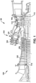
- FIG. 1 is a cross-sectional view of an illustrative machine including a turbine(s) (e.g., an expansion turbine or turbine section) within which teachings of the disclosure can be applied.
- a turbomachine 90 in the form of a combustion turbine or gas turbine (GT) system 100 (hereinafter, "GT system 100") is shown.
- GT system 100 includes a compressor 102 and a combustor 104.
- Combustor 104 includes a combustion region 105 and a fuel nozzle section 106.
- GT system 100 also includes a turbine 108 and a common compressor/turbine shaft 110 (hereinafter referred to as "rotor 110").
- rotor 110 common compressor/turbine shaft 110
- GT system 100 may be, for example, a 7HA.03 engine, commercially available from General Electric Company, Greenville, S.C.
- the present disclosure is not limited to any one particular GT system and may be implemented in connection with other engines including, for example, the other HA, F, B, LM, GT, TM and E-class engine models of General Electric Company and engine models of other companies.
- teachings of the disclosure are not necessarily applicable to only a turbine in a GT system and may be applied to practically any type of industrial machine or other turbine, e.g., steam turbines, jet engines, compressors (as in FIG. 1 ), turbofans, turbochargers, etc.
- turbine 108 of GT system 100 is merely for descriptive purposes and is not limiting.
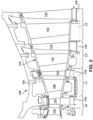
- FIG. 2 shows a cross-sectional view of an illustrative portion of turbine 108.
- turbine 108 includes four stages LO-L3 that may be used with GT system 100 in FIG. 1 .
- the four stages are referred to as L0, L1, L2, and L3.
- Stage L0 is the first stage and is the smallest (in a radial direction) of the four stages.
- Stage L1 is the second stage and is disposed adjacent the first stage L0 in an axial direction.
- Stage L2 is the third stage and is disposed adjacent the second stage L1 in an axial direction.
- Stage L3 is the fourth, last stage and is the largest (in a radial direction). It is to be understood that four stages are shown as one example only, and each turbine may have more or less than four stages.
- a plurality of stationary turbine vanes or nozzles 112 may cooperate with a plurality of rotating turbine blades 114 (hereafter “blade 114,” or “blades 114”) to form each stage L0-L3 of turbine 108 and to define a portion of a working fluid path through turbine 108.
- Blades 114 in each stage are coupled to rotor 110 ( FIG. 1 ), e.g., by a respective rotor wheel 116 that couples them circumferentially to rotor 110 ( FIG. 1 ). That is, blades 114 are mechanically coupled in a circumferentially spaced manner to rotor 110, e.g., by rotor wheels 116.
- a static nozzle section 115 includes a plurality of nozzles 112 mounted to a casing 124 and circumferentially spaced around rotor 110 ( FIG. 1 ). It is recognized that blades 114 rotate with rotor 110 ( FIG. 1 ) and thus experience centrifugal force, while nozzles 112 are static.
- the pressurized air is supplied to fuel nozzle section 106 that is integral to combustor 104.
- Fuel nozzle section 106 is in flow communication with combustion region 105.
- Fuel nozzle section 106 is also in flow communication with a fuel source (not shown in FIG. 1 ) and channels fuel and air to combustion region 105.
- Combustor 104 ignites and combusts fuel to produce combustion gases.
- Combustor 104 is in flow communication with turbine 108, within which thermal energy from the combustion gas stream is converted to mechanical rotational energy by directing the combusted fuel (e.g., working fluid) into the working fluid path to turn blades 114.
- Turbine 108 is rotatably coupled to and drives rotor 110.
- Compressor 102 may also be rotatably coupled to rotor 110. At least one end of rotor 110 may extend axially away from compressor 102 or turbine 108 and may be attached to a load or machinery (not shown), such as, but not limited to, a generator, a load compressor, and/or another turbine.
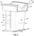
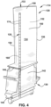
- FIGS. 3 and 4 show perspective views, respectively, of a (stationary) nozzle 112 and a (rotating) blade 114, of the type in which embodiments of a vibration dampening system 120 of the present disclosure may be employed.
- FIGS. 5 and 6 show schematic cross-sectional views of a nozzle 112 or blade 114 including vibration dampening system 120, according to various embodiments of the disclosure.
- each nozzle 112 or blade 114 includes a body 128 having a base end 130, a tip end 132, and an airfoil 134 extending between base end 130 and tip end 132.
- nozzle 112 includes an outer endwall 136 at base end 130 and an inner endwall 138 at tip end 132. Outer endwall 136 couples to casing 124 ( FIG. 2 ).
- blade 114 includes a dovetail 140 at base end 130 by which blade 114 attaches to a rotor wheel 116 ( FIG. 2 ) of rotor 110 ( FIG. 2 ).
- Base end 130 of blade 114 may further include a shank 142 that extends between dovetail 140 and a platform 146.
- Platform 146 is disposed at the junction of airfoil 134 and shank 142 and defines a portion of the inboard boundary of the working fluid path ( FIG. 2 ) through turbine 108.
- airfoil 134 in nozzle 112 and blade 114 is the active component of the nozzle 112 or blade 114 that intercepts the flow of working fluid and, in the case of blades 114, induces rotor 110 ( FIG. 1 ) to rotate. It will be seen that airfoil 134 of nozzle 112 and blade 114 include a concave pressure side (PS) outer sidewall 150 and a circumferentially or laterally opposite convex suction side (SS) outer sidewall 152 extending axially between opposite leading and trailing edges 154, 156, respectively.
- PS concave pressure side
- SS convex suction side
- Sidewalls 150 and 152 also extend in the radial direction from base end 130 (i.e., outer endwall 136 for nozzle 112 and platform 146 for blade 114) to tip end 132 (i.e., inner endwall 138 for nozzle 112 and a tip end 158 for blade 114).
- base end 130 i.e., outer endwall 136 for nozzle 112 and platform 146 for blade 11
- tip end 132 i.e., inner endwall 138 for nozzle 112 and a tip end 158 for blade 114.
- Nozzle 112 and blade 114 shown in FIGS. 3-4 are illustrative only, and the teachings of the disclosure can be applied to a wide variety of nozzles and blades.
- nozzles 112 or blades 114 may be excited into vibration by a number of different forcing functions. For example, variations in working fluid temperature, pressure, and/or density can excite vibrations throughout the rotor assembly, especially within the airfoils and/or tips of the blades 114 or nozzles 112. Gas exiting upstream of the turbine and/or compressor sections in a periodic (or "pulsating") manner can also excite undesirable vibrations. Embodiments of the present disclosure reduce the vibration of a stationary nozzle 112 or rotating turbine blade 114 without significant change of nozzle or blade design.
- FIGS. 5 and 6 each show a schematic cross-sectional view of nozzle 112 or blade 114 including vibration dampening system 120 according to embodiments of the disclosure.
- Nozzle 112 in the schematic cross-sectional views of FIGS. 5-6 is shown flipped vertically compared to that shown in FIG. 3 and without inner endwall 138, for ease of description. It should be understood that references to base end 130 and tip end 132 may be reversed for nozzle 112, as compared to blade 114.
- Vibration dampening system 120 for nozzle 112 or blade 114 may include a body opening 160 extending through body 128 at least partially between tip end 132 and base end 130 thereof and through airfoil 134.
- Body opening 160 may extend part of the distance between base end 130 and tip end 132, or it may extend through one or more of base end 130 or tip end 132. Body opening 160 may be defined in any part of any structure of body 128. For example, where body 128 includes an internal partition wall (not shown), for example, for defining a cooling circuit therein, body opening 160 may be defined as an internal cavity in the partition wall in body 128. Body opening 160 generally extends radially in body 128. However, some angling, and perhaps curving, of body opening 160 relative to a radial extent of body 128 is possible. Body opening 160 has an inner surface 162.
- body opening 160 may originate at base end 130 of nozzle 112 or blade 114, or, as shown in FIG. 6 , it may originate at tip end 132 of nozzle 112 or blade 114. More particularly, as shown in FIG. 5 , body opening 160 may be open in base end 130 and terminate in tip end 132, or, as shown in FIG. 6 , it may be open in tip end 132 and terminate in base end 130. The open end may assist in assembly of vibration dampening system 120 in nozzle 112 or blade 114 and may allow retrofitting of the system into an existing nozzle or blade. Where body opening 160 extends through base end 130 as shown in FIG. 5 , a closure member 164 for closing body opening 160 may be provided. Where body opening 160 extends through tip end 132, as shown in FIG. 6 , a closure member 166 for body opening 160 may be provided. In addition to closing body opening 160, closure members 164, 166 prevent removal of vibration dampening system 120 from body opening 160.
- Vibration dampening system 120 for nozzles 112 or blades 114 may include a plurality of stacked damper pins 174. As shown in the enlarged cross-sectional views of FIGS. 7 and 8 , each damper pin 174 may include an outer body 176 having defined therein an inner opening 178 and a plurality of side openings 180 extending from inner opening 178 through an outer surface 182 of outer body 176. Outer body 176 may also include a first end surface 184 and an opposing second end surface 186.
- Outer body 176 may have outer surface 182 of a shape and dimension to fit within body opening 160. More particularly, body opening 160 has inner surface 162 having an inner dimension ID1, and each outer body 176 has an outer dimension OD1 sized to slidingly fit (but not necessarily fully engage) inner dimension ID1 of body opening 160. That is, outer dimension OD1 of outer body 176 of each damper pin 174 does not always rub or contact against inner surface 162 of body opening 160. During assembly, inner dimension ID1 and outer dimension OD1 are sized to allow damper pins 174 to be positioned in body opening 160.
- a difference between outer dimension OD1 of outer body 176 of damper pins 174 and inner dimension ID1 of inner surface 162 of body opening 160 may be in a range of approximately 1 to 10 millimeters (mm), which allows insertion of damper pins 174 and relative movement thereof in airfoil 134 of nozzle 112 or blade 114.
- First end surface 184 and second end surface 186 of outer body 176 are complementary of one another, i.e., they fit together, so they can frictionally engage one another.
- first end surface 184 of outer body 176 is at least partially concave
- second end surface 186 of outer body 176 is at least partially convex. In this manner, first end surface 184 and second end surface 186 of adjacent damper pins 174 can frictionally engage and rotationally move relative to one another as nozzle 112 or blade 114 moves.
- End surfaces 184, 186 need not be contiguous surfaces, and may be partitioned (as shown), e.g., to reduce unnecessary weight from each damper pin 174.
- damper pins 174 dampen vibration is by having outer bodies 176 of adjacent pins frictionally engage each other, i.e., via end surfaces 184, 186. In nozzles 112, damper pins 174 frictionally engage under the influence of the force of their collective weight, and in blades 112, damper pins 174 frictionally engage under the influence of their collective weight and centrifugal forces exerted on the blade during rotation thereof.
- Outer body 176 also includes inner opening 178 extending through first end surface 184 and second end surface 186. As will be described, inner opening 178 has a number of different surfaces to accommodate different portions of an inner body 190.
- Each damper pin 174 may also include inner body 190 nested and movable within inner opening 178 of outer body 176.
- Inner body 190 moves independently of outer body 176.
- Inner body 190 includes a first portion 192 ( FIGS. 7-8 ) including a plurality of arms 194.
- Each arm 194 extends through a respective side opening 180 of plurality of side openings 180 of outer body 176.
- Plurality of arms 194 collectively define an outer dimension OD2 greater than an outer dimension OD1 of outer body 176.
- Outer dimension OD2 of arms 194 is configured to engage inner surface 162 of body opening 160 in turbine nozzle 112 or blade 114 in which the damper pin 174 is positioned as turbine nozzle 112 or blade 114 vibrates.
- any number of arms 194 and respective side openings 180 can be provided so long as sliding movement between outer body 176 and inner body 190 can occur, e.g., two, three, five or six arms are possible. While shown as equal in numbers, not all side openings 180 require an arm 194 therein, i.e., some may be empty. Side openings 180 are sized so as to not interfere with movement of arms 194 during operation of vibration dampening system 120. An outer dimension of outer body 176 may taper where side openings 180 are defined therein, e.g., to reduce weight and an amount of required material.
- Arms 194 may have any shape to provide sufficient structural strength to move inner body 190 relative to outer body 176.
- arms 194 have a generally triangular shape with a flattened outer end 195 that engages inner surface 162 of body opening 160.
- Flattened outer ends 195 may be configured to be parallel to inner surface 162 of body opening 160, e.g., during insertion of damper pins 174.
- flattened outer ends 195 of arms 194 may be slightly angled from parallel to inner surface 162 of body opening 160 to, for example, assist insertion of damper pins 174 and ensure non-binding engagement with inner surface 162 of body opening 160 during use.
- Flattened outer ends 195 can have any surface roughness, e.g., rougher than inner surface 162 of body opening 160, to ensure proper insertion and operational engagement with inner surface 162 of body opening 160.
- Inner body 190 and inner opening 178 of outer body 176 may take a variety of forms.
- inner body 190 has a second portion 196 configured to frictionally engage a first section 198 of inner opening 178 of outer body 176.
- outer surface 200 of second portion 196 of inner body 190 may have a bulbous portion 202
- first section 198 of inner opening 178 of outer body 176 may have a complementary concave surface 204 to bulbous portion 202.
- bulbous portion 202 and concave surface 204 may frictionally engage as inner body 190 moves laterally or tilts in outer body 176 during vibration and/or bending of nozzle 112 or blade 114.
- Bulbous portion 202 can be internally solid or hollow (for the latter, see FIG. 10 ).
- the engagement of bulbous portion 202 and concave surface 204 are configured to delimit the extent of radial movement (relative to the turbine axis) of inner body 190 relative to a respective outer body 176.
- Inner body 190 may also include a third portion 210 extending through one of first end surface 184 and second end surface 186 from inner opening 178.
- third portion 210 extends through second end surface 186 from inner opening 178.
- third portion 210 extends through a second section 212 of inner opening 178 of outer body 176 in a (radially) spaced manner.
- Third portion 210 of inner body 190 may have any shape configured to pass through second section 212.
- third portion 210 includes a cylindrical element 214 extending axially from first portion 192 including plurality of arms 194. As shown in FIG. 7 , third portion 210 may extend out past end surface 186 of outer body 176, or, as shown in FIG.
- first portion 192 of inner body 190 is positioned between second portion 196 (with bulbous portion 202) and third portion 210 of inner body 190.
- second section 212 of inner opening 178 of outer body 176 is spaced from third portion 210 of inner body 190 by a distance D that delimits an amount of side-to-side tilting movement of inner body 190 within outer body 176 during use. More particularly, as shown in FIG. 9 , as inner body 190 moves within outer body 176 under the encouragement of arms 194 engaging inner surface 162 of body opening 160, third portion 210 of inner body 190 can move side-to-side until it contacts second section 212 of inner opening 178.
- Portions 192, 196, 210 of inner body 190 are integral to one another, i.e., it is a unitary structure. However, inner bodies 190 of adjacent damper pins 174 do not contact one another and move independently of one another.
- damper pins 174 may be used in vibration dampening system 120 depending on, among other factors, the length of nozzle 112 or blade 114, desired vibration dampening, and/or available space.
- An endmost one of damper pins 174 in a stack may abut an end 252 of body opening 160, see e.g., FIG. 7 .
- retention damper pin 250 may be positioned to engage with an endmost one of the plurality of stacked damper pins 174.
- Retention damper pin 250 may act to protect the endmost one of the plurality of stacked damper pins 174 near end 252 of body opening 160. In this case, damper pins 174 abut retention damper pin 250 rather than end 252 of body opening 160, and retention damper pin 250 abuts end 252 of body opening 160.
- FIG. 5 shows an embodiment in which body opening 160 is closed at tip end 132 of nozzle 112 or blade 114, and closure member 164 closes base end 130.
- retention damper pin 250 is positioned at tip end 132 of nozzle 112 or blade 114 and stacked damper pins 174 to prevent stacked damper pins 174 from hitting end 252 of body opening 160.
- damper pins 174 may alternatively abut end 252 of body opening 160 in tip end 132.
- Centrifugal force (arrow CF) on a blade 114 will force stacked damper pins 174 against retention damper pin 250 and/or end 252 of body opening 160 in tip end 132 of body 128 of turbine blade 114 as the blade rotates.
- the weight of damper pins 174 will force them against closure member 164.
- Body opening 160 in base end 130 may be closed by any now known or later developed closure member 164.
- FIG. 6 shows an embodiment in which body opening 160 is closed at base end 130 of nozzle 112 or blade 114, and closure member 166 closes tip end 132.
- retention damper pin 250 is positioned at base end 130 of nozzle 112 or blade 114 and stacked damper pins 174 to prevent plurality of stacked damper pins 174 from hitting end 252 of body opening 160.
- damper pins 174 may alternatively abut end 252 of body opening 160 in base end 130.
- centrifugal force on blade 114 will force stacked damper pins 174 against closure member 166 in tip end 132 of body 128 of turbine blade 114 as the blade rotates.
- first end surface 184 and second end surface 186 of adjacent damper pins 174 frictionally engage and rotationally move relative to one another as nozzle 112 or blade 114 moves.
- damper pins 174 dampen vibration by having outer bodies 176 of adjacent damper pins 174 frictionally engage, i.e., via end surfaces 184, 186.
- damper pins 174 frictionally engage in this manner under the influence of the force of their collective weight, and in blades 112, damper pins 174 frictionally engage under the influence of their collective weight and centrifugal forces exerted on the blade during rotation thereof. Centrifugal forces are applied upwardly on the pages of FIGS. 5 and 6 - see arrow CF.
- Frictional engagement between surfaces 200, 204 may also occur under the influence of one or more of plurality of arms 194 engaging inner surface 162 of body opening 160 in turbine nozzle 112 or blade 114. More particularly, plurality of arms 194 provide the largest outer dimension OD2 of damper pins 174, so they contact inner surface 162 of body opening 160 before any other part of damper pins 174. This arrangement provides an earlier point of engagement (compared to outer surface 182 of outer body 176 engaging with inner surface 162 of body opening 160), which forces each damper pin 174 (i.e., inner body 190 thereof) to have more movement than predecessor damper pins, generating a larger amount of motion and more friction-based vibration dampening.
- frictional engagement can occur anywhere along the outer surfaces of inner body 190 and the inner surfaces of inner opening 178 of outer body 176, but mostly occurs at outer surface 200 of bulbous portion 202 of inner body 190 and concave surface 204 of first section 198 of outer body 176. For example, frictional engagement may occur near an upper portion (as illustrated on the page of FIG.
- each damper pin 174 (at end surfaces 184, 186 of outer body 176 thereof) experiences the centrifugal forces of any damper pins 174 radially inward thereof (relative to turbine axis), which can cause them to bind and/or not move smoothly across one another over time and provide diminished vibration dampening.
- inner bodies 190 are nested within outer bodies 176, frictionally engaging surfaces 200, 204 thereof do not experience as much force as frictionally engaging end surfaces 184, 186.
- Vibration dampening may also occur by frictional engagement of outer dimension OD1 of outer surface 182 of outer body 176 with inner dimension ID1 of inner surface 162 of body opening 160 in nozzle 112 or blade 114.
- a method of dampening vibration in turbine nozzle 112 or blade 114 may include, during operation of nozzle 112 or blade 114, a number of vibration dampening processes. Dampening vibration may occur by frictional engagement between and within a plurality of stacked damper pins 174. As noted, each damper pin 174 includes outer body 176 having inner opening 178, first end surface 184 and opposing second end surface 186. Vibration dampening may occur by frictional engagement of first end surface 184 and opposing second end surface 186 of adjacent damper pins 174. In FIGS. 5-7 and 9 , complementary concave-convex end surfaces 184, 186 frictionally engage to dampen vibration. As noted, end surfaces 184, 186 may have other complementary shapes allowing frictional engagement to dampen vibration.
- Each damper pin 174 also includes inner body 190 nested and movable within inner opening 178 of outer body 176. As described herein, additional vibration dampening occurs by frictional engagement of a portion of outer surface 200 of inner body 190 and a section 198 of inner opening 178 of outer body 176, e.g., concave surface 204, under influence of, among other forces, plurality of arms 194 engaging with inner surface 162 of body opening 160 in turbine nozzle 112 or blade 114. As noted, the method may also include vibration dampening by frictional engagement of outer dimension OD1 of outer surface 182 of outer body 176 with inner dimension ID1 of inner surface 162 of body opening 160 in nozzle 112 or blade 114.
- Damper pins 174 can be manufactured in any now known or later developed fashion.
- outer and inner bodies 176, 190 can be cast, with outer body 176 in halves, and the parts can be assembled, e.g., by welding or otherwise fastening of the halves of outer body 176 positioned about inner body 190.
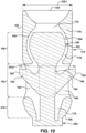
- outer body 176 and inner body 190 can be additively manufactured. Any form of additive manufacture appropriate for the materials used can be employed, such as but not limited to direct metal laser melting (DMLM). In this case, prior to separation after the additive manufacturing, outer body 176 and inner body 190 are integrally coupled and fixed relative to one another by a removable coupling element 260.
- DMLM direct metal laser melting
- outer body 176 can be additively manufactured with and about inner body 190 with each of outer body 176 and inner body 190 being formed as a single, unitary body.
- Coupling element 260 can then be removed using any method (e.g., by cutting at the dashed line shown in FIG. 10 ), resulting in inner body 190 being nested in and movable within outer body 176, as described herein.
- Vibration dampening system 120 reduces nozzle or blade vibration with a simple arrangement and does not add much extra mass to nozzle 112 or blade 114. Vibration dampening system 120 does not increase centrifugal force to nozzle 112 base end 130 or blade 114 tip end 132 or require a change in nozzle 112 or blade 114 configuration.
- the nested damper pins 174 allow use of stacked damper pins in which inner bodies 190 are free to continue frictional-based vibration dampening movement (via interaction of arms 194 with inner surface 162 of body opening 160) even if outer bodies 176 bind together from, e.g., the collective weight of the damper pins and/or centrifugal forces, at end surfaces 184, 186.
- Approximating language may be applied to modify any quantitative representation that could permissibly vary without resulting in a change in the basic function to which it is related. Accordingly, a value modified by a term or terms, such as “about,” “approximately” and “substantially,” are not to be limited to the precise value specified. In at least some instances, the approximating language may correspond to the precision of an instrument for measuring the value.
- range limitations may be combined and/or interchanged; such ranges are identified and include all the sub-ranges contained therein unless context or language indicates otherwise. "Approximately,” as applied to a particular value of a range, applies to both end values and, unless otherwise dependent on the precision of the instrument measuring the value, may indicate +/- 10% of the stated value(s).
Landscapes
- Engineering & Computer Science (AREA)
- Mechanical Engineering (AREA)
- Manufacturing & Machinery (AREA)
- General Engineering & Computer Science (AREA)
- Chemical & Material Sciences (AREA)
- Materials Engineering (AREA)
- Turbine Rotor Nozzle Sealing (AREA)
Abstract
Description
- The disclosure relates generally to dampening vibration in a turbine nozzle or blade. More specifically, the disclosure relates to a vibration dampening system including a plurality of nested damper pins.
- One concern in turbine operation is the tendency of the turbine blades or nozzles to undergo vibrational stress during operation. In many installations, turbines are operated under conditions of frequent acceleration and deceleration. During acceleration or deceleration of the turbine, the airfoils of the blades are, momentarily at least, subjected to vibrational stresses at certain resonant frequencies and, in many cases, to vibrational stresses at secondary or tertiary frequencies. Nozzle airfoils experience similar vibrational stress. Variations in gas temperature, pressure, and/or density, for example, can excite vibrations throughout the rotor assembly, especially within the nozzle or blade airfoils. Gas exiting upstream of the turbine and/or compressor sections in a periodic, or "pulsating," manner can also excite undesirable vibrations. When an airfoil is subjected to vibrational stress, its amplitude of vibration can readily build up to a point which may negatively affect gas turbine operations and/or component life. Previously, stacked, solid damper pins in a turbine blade have been used to dampen vibration, but the centrifugal forces can result in locking of the damper pins together, reducing their ability to dampen vibration.
- All aspects, examples and features mentioned below can be combined in any technically possible way.
- An aspect of the disclosure provides a damper pin for a vibration dampening system for a turbine nozzle or blade, the damper pin comprising: an outer body having defined therein an inner opening and a plurality of side openings extending from the inner opening through an outer surface of the outer body; and an inner body nested and movable within the inner opening of the outer body, the inner body including a first portion including a plurality of arms, each arm extending through a respective side opening of the plurality of side openings of the outer body.
- Another aspect of the disclosure includes any of the preceding aspects, and the plurality of arms defines an outer dimension greater than an outer dimension of the outer body, the outer dimension being configured to engage an inner surface of a body opening in the turbine nozzle or blade in which the damper pin is positioned.
- Another aspect of the disclosure includes any of the preceding aspects, and the inner body further includes: a second portion having an outer surface configured to frictionally engage a first section of the inner opening of the outer body, a third portion extending through a second section of the inner opening of the outer body in a spaced manner, and wherein the first portion of the inner body including the plurality of arms is positioned between the second portion and the third portion of the inner body.
- Another aspect of the disclosure includes any of the preceding aspects, and the outer surface of the second portion of the inner body has a bulbous portion, and the first section of the inner opening of the outer body has a complementary concave surface to the bulbous portion.
- Another aspect of the disclosure includes any of the preceding aspects, and the second section of the inner opening of the outer body is spaced from the third portion of the inner body by a distance that delimits an amount of side-to-side tilting movement of the inner body within the outer body.
- Another aspect of the disclosure includes any of the preceding aspects, and the outer surface of the inner body and the first section of the inner opening of the outer body frictionally engage under influence of the plurality of arms engaging an inner surface of a body opening in the turbine nozzle or blade.
- Another aspect of the disclosure includes any of the preceding aspects, and the outer body further includes a first end surface and an opposing second end surface, and wherein the inner opening of the outer body extends through the first end surface and the second end surface, wherein the third portion of the inner body extends through one of the first and second end surfaces from the inner opening.
- Another aspect of the disclosure includes any of the preceding aspects, and wherein the damper pin is one of a plurality of identical damper pins in the vibration dampening system; and the first end surface of the outer body of each respective damper pin is at least partially concave, and the second end surface of the outer body of each respective damper pin is at least partially convex, whereby the first end surface of the damper pin is configured to frictionally engage the second end surface of an adjacent damper pin.
- Another aspect of the disclosure includes any of the preceding aspects, and the outer body and the inner body are additively manufactured, and wherein, prior to separation after the additive manufacturing, the outer body and the inner body are integrally coupled and fixed relative to one another by a removable coupling element.
- Another aspect of the disclosure includes a vibration dampening system for a turbine nozzle or blade, the vibration dampening system comprising: a plurality of stacked damper pins, each damper pin including: an outer body having defined therein an inner opening and a plurality of side openings extending from the inner opening through an outer surface of the outer body; and an inner body nested and movable within the inner opening of the outer body, the inner body including a first portion including a plurality of arms, each arm extending through a respective side opening of the plurality of side openings of the outer body.
- Another aspect of the disclosure includes any of the preceding aspects, and the plurality of arms define an outer dimension greater than an outer dimension of the outer body, the outer dimension being configured to engage an inner surface of a body opening in the turbine nozzle or blade in which the damper pin is positioned.
- Another aspect of the disclosure includes any of the preceding aspects, and the inner body further includes: a second portion having an outer surface configured to frictionally engage a first section of the inner opening of the outer body, a third portion extending through a second section of the inner opening of the outer body in a spaced manner, and wherein the first portion of the inner body including the plurality of arms is positioned between the second portion and the third portion of the inner body.
- Another aspect of the disclosure includes any of the preceding aspects, and the outer surface of the second portion of the inner body has a bulbous portion, and the first section of the inner opening of the outer body has a complementary concave surface to the bulbous portion.
- Another aspect of the disclosure includes any of the preceding aspects, and the second section of the inner opening of the outer body is spaced from the third portion of the inner body by a distance that delimits an amount of side-to-side tilting movement of the inner body within the outer body.
- Another aspect of the disclosure includes any of the preceding aspects, and the outer surface of the inner body and the first section of the inner opening of the outer body frictionally engage under influence of the plurality of arms engaging an inner surface of a body opening in the turbine nozzle or blade.
- Another aspect of the disclosure includes any of the preceding aspects, and the outer body further includes a first end surface and an opposing second end surface, and wherein the inner opening of the outer body extends through the first end surface and the second end surface, wherein the third portion of the inner body extends through one of the first and second end surfaces from the inner opening.
- Another aspect of the disclosure includes any of the preceding aspects, and the first end surface of the outer body is at least partially concave, and the second end surface of the outer body is at least partially convex, whereby the first end surface and the second end surface of adjacent damper pins frictionally engage.
- Another aspect of the disclosure includes any of the preceding aspects, and the outer body and the inner body are additively manufactured, and wherein, prior to separation after the additive manufacturing, the outer body and the inner body are integrally coupled and fixed relative to one another by a removable coupling element.
- Another aspect of the disclosure includes any of the preceding aspects, and further comprising a retention damper pin engaging with an endmost one of the plurality of stacked damper pins.
- Another aspect of the disclosure includes a method of dampening vibration in a turbine nozzle or blade, the method comprising: during operation of the turbine nozzle or blade, dampening vibration by frictional engagement between and within a plurality of stacked damper pins, each damper pin including: an outer body having an inner opening, a first end surface and an opposing second end surface, wherein first vibration dampening occurs by frictional engagement of the first end surface and the opposing second end surface of an adjacent damper pin; and an inner body nested and movable within the inner opening of the outer body, wherein second vibration dampening occurs by frictional engagement of a portion of an outer surface of the inner body and a section of the inner opening of the outer body under influence of a plurality of arms extending from the inner body through the outer body and engaging with an inner surface of a body opening in the turbine nozzle or blade.
- Two or more aspects described in this disclosure, including those described in this summary section, may be combined to form implementations not specifically described herein.
- The details of one or more implementations are set forth in the accompanying drawings and the description below. Other features, objects and advantages will be apparent from the description and drawings, and from the claims.
- These and other features of this disclosure will be more readily understood from the following detailed description of the various aspects of the disclosure taken in conjunction with the accompanying drawings that depict various embodiments of the disclosure, in which:
-
FIG. 1 shows a cross-sectional view of an illustrative turbomachine in the form of a gas turbine system including a turbine section; -
FIG. 2 shows a cross-sectional view of a portion of an illustrative turbine section as may be used in the turbomachine ofFIG. 1 , according to embodiments of the disclosure; -
FIG. 3 shows a perspective view of an illustrative turbine nozzle including a vibration dampening system, according to embodiments of the disclosure; -
FIG. 4 shows a perspective view of an illustrative turbine blade including a vibration dampening system, according to embodiments of the disclosure; -
FIG. 5 shows a schematic cross-sectional view of a turbine nozzle or blade having a vibration dampening system including a plurality of damper pins, according to embodiments of the disclosure; -
FIG. 6 shows a schematic cross-sectional view of a turbine nozzle or blade having a vibration dampening system including a plurality of damper pins, according to embodiments of the disclosure; -
FIG. 7 shows a cross-sectional enlarged view of a pair of damper pins ofFIG. 5 , each damper pin including an outer body and an inner body, according to embodiments of the disclosure; -
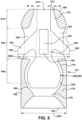
FIG. 8 shows a cross-sectional view of a damper pin ofFIGS. 5-7 , which includes an outer body and an inner body, according to other embodiments of the disclosure; -
FIG. 9 shows a cross-sectional view of a damper pin ofFIGS. 5-8 with an inner body thereof in frictional engagement with an outer body thereof, according to embodiments of the disclosure; and -
FIG. 10 shows a cross-sectional view of an additively manufactured damper pin, according to embodiments of the disclosure. - It is noted that the drawings of the disclosure are not necessarily to scale. The drawings are intended to depict only typical aspects of the disclosure and therefore should not be considered as limiting the scope of the disclosure. In the drawings, like numbering represents like elements between the drawings.
- As an initial matter, in order to clearly describe the subject matter of the current disclosure, it will become necessary to select certain terminology when referring to and describing relevant machine components within a turbine. To the extent possible, common industry terminology will be used and employed in a manner consistent with its accepted meaning. Unless otherwise stated, such terminology should be given a broad interpretation consistent with the context of the present application and the scope of the appended claims. Those of ordinary skill in the art will appreciate that often a particular component may be referred to using several different or overlapping terms. What may be described herein as being a single part may include and be referenced in another context as consisting of multiple components. Alternatively, what may be described herein as including multiple components may be referred to elsewhere as a single part.
- In addition, several descriptive terms may be used regularly herein, and it should prove helpful to define these terms at the onset of this section. It is often required to describe parts that are disposed at different radial positions with regard to a center axis. The term "radial" refers to movement or position perpendicular to an axis. For example, if a first component resides closer to the axis than a second component, it will be stated herein that the first component is "radially inward" or "inboard" of the second component. If, on the other hand, the first component resides further from the axis than the second component, it may be stated herein that the first component is "radially outward" or "outboard" of the second component. The term "axial" refers to movement or position parallel to an axis. Finally, the term "circumferential" refers to movement or position around an axis. It will be appreciated that such terms may be applied in relation to a center axis of a damper pin, the center axis of a turbine blade or nozzle, or the center axis of the turbine.
- In addition, several descriptive terms may be used regularly herein, as described below. The terms "first," "second," and "third," may be used interchangeably to distinguish one component from another and are not intended to signify location or importance of the individual components.
- The terminology used herein is for the purpose of describing particular embodiments only and is not intended to be limiting of the disclosure. As used herein, the singular forms "a," "an," and "the" are intended to include the plural forms as well, unless the context clearly indicates otherwise. It will be further understood that the terms "comprises" and/or "comprising," when used in this specification, specify the presence of stated features, integers, steps, operations, elements, and/or components but do not preclude the presence or addition of one or more other features, integers, steps, operations, elements, components, and/or groups thereof. "Optional" or "optionally" means that the subsequently described event or circumstance may or may not occur or that the subsequently described component or element may or may not be present, and that the description includes instances where the event occurs or the component is present and instances where it does not or is not present.
- Where an element or layer is referred to as being "on," "engaged to," "connected to" or "coupled to" another element or layer, it may be directly on, engaged to, connected to, or coupled to the other element or layer, or intervening elements or layers may be present. In contrast, when an element is referred to as being "directly on," "directly engaged to," "directly connected to" or "directly coupled to" another element or layer, there are no intervening elements or layers present. Other words used to describe the relationship between elements should be interpreted in a like fashion (e.g., "between" versus "directly between," "adjacent" versus "directly adjacent," etc.). As used herein, the term "and/or" includes any and all combinations of one or more of the associated listed items.
- Embodiments of the disclosure provide a vibration dampening system for a turbine nozzle or blade. A body opening extends through the turbine nozzle or blade, e.g., through the airfoil among potentially other parts of the nozzle or blade. The vibration dampening system includes a plurality of stacked damper pins within the body opening. The damper pins each include an outer body having defined therein an inner opening and a plurality of side openings extending from the inner opening through an outer surface of the outer body, and an inner body is nested and movable within the inner opening of the outer body. Hence, the damper pins may be referenced as "nested damper pins" because they include nested parts that frictionally engage with each other to dampen vibration. The inner body includes a first portion including a plurality of arms, each arm extending through a respective side opening of the plurality of side openings of the outer body. The inner body also includes a second portion including an outer surface configured to frictionally engage a section of the inner opening of the outer body to dampen vibration. In addition, the end surfaces of the outer bodies of adjacent damper pins frictionally engage with adjacent damper pins to dampen vibration.
- The vibration dampening system reduces nozzle or blade vibration with a simple arrangement and does not add much extra mass to the nozzle or blade. Accordingly, the vibration dampening system and pins do not increase centrifugal force to the nozzle base end or blade tip end or require a change in nozzle or blade configuration. The nested damper pins allow use of stacked damper pins in which the inner bodies thereof are free to continue frictional-based vibration dampening movement (via interaction of the arms with an inner surface of the body opening in the turbine nozzle or blade), even if the end surfaces of the outer bodies lock together, e.g., as may occur in turbine blades as a result of centrifugal forces experienced by blades.
- Referring to the drawings,
FIG. 1 is a cross-sectional view of an illustrative machine including a turbine(s) (e.g., an expansion turbine or turbine section) within which teachings of the disclosure can be applied. InFIG. 1 , aturbomachine 90 in the form of a combustion turbine or gas turbine (GT) system 100 (hereinafter, "GT system 100") is shown.GT system 100 includes acompressor 102 and acombustor 104.Combustor 104 includes acombustion region 105 and afuel nozzle section 106.GT system 100 also includes aturbine 108 and a common compressor/turbine shaft 110 (hereinafter referred to as "rotor 110"). -
GT system 100 may be, for example, a 7HA.03 engine, commercially available from General Electric Company, Greenville, S.C. The present disclosure is not limited to any one particular GT system and may be implemented in connection with other engines including, for example, the other HA, F, B, LM, GT, TM and E-class engine models of General Electric Company and engine models of other companies. More importantly, the teachings of the disclosure are not necessarily applicable to only a turbine in a GT system and may be applied to practically any type of industrial machine or other turbine, e.g., steam turbines, jet engines, compressors (as inFIG. 1 ), turbofans, turbochargers, etc. Hence, reference toturbine 108 ofGT system 100 is merely for descriptive purposes and is not limiting. -
FIG. 2 shows a cross-sectional view of an illustrative portion ofturbine 108. In the example shown,turbine 108 includes four stages LO-L3 that may be used withGT system 100 inFIG. 1 . The four stages are referred to as L0, L1, L2, and L3. Stage L0 is the first stage and is the smallest (in a radial direction) of the four stages. Stage L1 is the second stage and is disposed adjacent the first stage L0 in an axial direction. Stage L2 is the third stage and is disposed adjacent the second stage L1 in an axial direction. Stage L3 is the fourth, last stage and is the largest (in a radial direction). It is to be understood that four stages are shown as one example only, and each turbine may have more or less than four stages. - A plurality of stationary turbine vanes or nozzles 112 (hereafter "
nozzle 112," or "nozzles 112") may cooperate with a plurality of rotating turbine blades 114 (hereafter "blade 114," or "blades 114") to form each stage L0-L3 ofturbine 108 and to define a portion of a working fluid path throughturbine 108.Blades 114 in each stage are coupled to rotor 110 (FIG. 1 ), e.g., by arespective rotor wheel 116 that couples them circumferentially to rotor 110 (FIG. 1 ). That is,blades 114 are mechanically coupled in a circumferentially spaced manner torotor 110, e.g., byrotor wheels 116. Astatic nozzle section 115 includes a plurality ofnozzles 112 mounted to acasing 124 and circumferentially spaced around rotor 110 (FIG. 1 ). It is recognized thatblades 114 rotate with rotor 110 (FIG. 1 ) and thus experience centrifugal force, whilenozzles 112 are static. - With reference to
FIGS. 1 and2 , in operation, air flows throughcompressor 102, and pressurized air is supplied tocombustor 104. Specifically, the pressurized air is supplied tofuel nozzle section 106 that is integral tocombustor 104.Fuel nozzle section 106 is in flow communication withcombustion region 105.Fuel nozzle section 106 is also in flow communication with a fuel source (not shown inFIG. 1 ) and channels fuel and air tocombustion region 105.Combustor 104 ignites and combusts fuel to produce combustion gases.Combustor 104 is in flow communication withturbine 108, within which thermal energy from the combustion gas stream is converted to mechanical rotational energy by directing the combusted fuel (e.g., working fluid) into the working fluid path to turnblades 114.Turbine 108 is rotatably coupled to and drivesrotor 110.Compressor 102 may also be rotatably coupled torotor 110. At least one end ofrotor 110 may extend axially away fromcompressor 102 orturbine 108 and may be attached to a load or machinery (not shown), such as, but not limited to, a generator, a load compressor, and/or another turbine. -
FIGS. 3 and4 show perspective views, respectively, of a (stationary)nozzle 112 and a (rotating)blade 114, of the type in which embodiments of avibration dampening system 120 of the present disclosure may be employed. As will be described herein,FIGS. 5 and6 show schematic cross-sectional views of anozzle 112 orblade 114 includingvibration dampening system 120, according to various embodiments of the disclosure. - Referring to
FIGS. 3 and4 , eachnozzle 112 orblade 114 includes abody 128 having abase end 130, atip end 132, and anairfoil 134 extending betweenbase end 130 andtip end 132. As shown inFIG. 3 ,nozzle 112 includes anouter endwall 136 atbase end 130 and aninner endwall 138 attip end 132. Outer endwall 136 couples to casing 124 (FIG. 2 ). As shown inFIG. 4 ,blade 114 includes adovetail 140 atbase end 130 by whichblade 114 attaches to a rotor wheel 116 (FIG. 2 ) of rotor 110 (FIG. 2 ).Base end 130 ofblade 114 may further include ashank 142 that extends betweendovetail 140 and aplatform 146.Platform 146 is disposed at the junction ofairfoil 134 andshank 142 and defines a portion of the inboard boundary of the working fluid path (FIG. 2 ) throughturbine 108. - It will be appreciated that
airfoil 134 innozzle 112 andblade 114 is the active component of thenozzle 112 orblade 114 that intercepts the flow of working fluid and, in the case ofblades 114, induces rotor 110 (FIG. 1 ) to rotate. It will be seen thatairfoil 134 ofnozzle 112 andblade 114 include a concave pressure side (PS)outer sidewall 150 and a circumferentially or laterally opposite convex suction side (SS)outer sidewall 152 extending axially between opposite leading and trailingedges Sidewalls outer endwall 136 fornozzle 112 andplatform 146 for blade 114) to tip end 132 (i.e.,inner endwall 138 fornozzle 112 and atip end 158 for blade 114). Note, in the example shown, althoughblade 114 does not include a tip shroud, teachings of the disclosure are equally applicable to a blade including a tip shroud attip end 158.Nozzle 112 andblade 114 shown inFIGS. 3-4 are illustrative only, and the teachings of the disclosure can be applied to a wide variety of nozzles and blades. - During operation of a turbine,
nozzles 112 orblades 114 may be excited into vibration by a number of different forcing functions. For example, variations in working fluid temperature, pressure, and/or density can excite vibrations throughout the rotor assembly, especially within the airfoils and/or tips of theblades 114 ornozzles 112. Gas exiting upstream of the turbine and/or compressor sections in a periodic (or "pulsating") manner can also excite undesirable vibrations. Embodiments of the present disclosure reduce the vibration of astationary nozzle 112 orrotating turbine blade 114 without significant change of nozzle or blade design. -
FIGS. 5 and6 each show a schematic cross-sectional view ofnozzle 112 orblade 114 includingvibration dampening system 120 according to embodiments of the disclosure. (Nozzle 112 in the schematic cross-sectional views ofFIGS. 5-6 is shown flipped vertically compared to that shown inFIG. 3 and withoutinner endwall 138, for ease of description. It should be understood that references tobase end 130 andtip end 132 may be reversed fornozzle 112, as compared toblade 114.)Vibration dampening system 120 fornozzle 112 orblade 114 may include abody opening 160 extending throughbody 128 at least partially betweentip end 132 andbase end 130 thereof and throughairfoil 134.Body opening 160 may extend part of the distance betweenbase end 130 andtip end 132, or it may extend through one or more ofbase end 130 ortip end 132.Body opening 160 may be defined in any part of any structure ofbody 128. For example, wherebody 128 includes an internal partition wall (not shown), for example, for defining a cooling circuit therein, body opening 160 may be defined as an internal cavity in the partition wall inbody 128.Body opening 160 generally extends radially inbody 128. However, some angling, and perhaps curving, of body opening 160 relative to a radial extent ofbody 128 is possible.Body opening 160 has aninner surface 162. - As shown in
FIG. 5 , body opening 160 may originate atbase end 130 ofnozzle 112 orblade 114, or, as shown inFIG. 6 , it may originate attip end 132 ofnozzle 112 orblade 114. More particularly, as shown inFIG. 5 , body opening 160 may be open inbase end 130 and terminate intip end 132, or, as shown inFIG. 6 , it may be open intip end 132 and terminate inbase end 130. The open end may assist in assembly ofvibration dampening system 120 innozzle 112 orblade 114 and may allow retrofitting of the system into an existing nozzle or blade. Wherebody opening 160 extends throughbase end 130 as shown inFIG. 5 , aclosure member 164 for closingbody opening 160 may be provided. Wherebody opening 160 extends throughtip end 132, as shown inFIG. 6 , aclosure member 166 forbody opening 160 may be provided. In addition to closingbody opening 160,closure members vibration dampening system 120 frombody opening 160. -
Vibration dampening system 120 fornozzles 112 orblades 114 may include a plurality of stacked damper pins 174. As shown in the enlarged cross-sectional views ofFIGS. 7 and8 , eachdamper pin 174 may include anouter body 176 having defined therein aninner opening 178 and a plurality ofside openings 180 extending frominner opening 178 through anouter surface 182 ofouter body 176.Outer body 176 may also include afirst end surface 184 and an opposingsecond end surface 186. -
Outer body 176 may haveouter surface 182 of a shape and dimension to fit withinbody opening 160. More particularly, body opening 160 hasinner surface 162 having an inner dimension ID1, and eachouter body 176 has an outer dimension OD1 sized to slidingly fit (but not necessarily fully engage) inner dimension ID1 ofbody opening 160. That is, outer dimension OD1 ofouter body 176 of eachdamper pin 174 does not always rub or contact againstinner surface 162 ofbody opening 160. During assembly, inner dimension ID1 and outer dimension OD1 are sized to allowdamper pins 174 to be positioned inbody opening 160. In one non-limiting example, a difference between outer dimension OD1 ofouter body 176 of damper pins 174 and inner dimension ID1 ofinner surface 162 ofbody opening 160 may be in a range of approximately 1 to 10 millimeters (mm), which allows insertion of damper pins 174 and relative movement thereof inairfoil 134 ofnozzle 112 orblade 114. -
First end surface 184 andsecond end surface 186 ofouter body 176 are complementary of one another, i.e., they fit together, so they can frictionally engage one another. In theFIGS. 5-8 embodiments,first end surface 184 ofouter body 176 is at least partially concave, andsecond end surface 186 ofouter body 176 is at least partially convex. In this manner,first end surface 184 andsecond end surface 186 of adjacent damper pins 174 can frictionally engage and rotationally move relative to one another asnozzle 112 orblade 114 moves. End surfaces 184, 186 need not be contiguous surfaces, and may be partitioned (as shown), e.g., to reduce unnecessary weight from eachdamper pin 174. Other complementary shapes forend surfaces outer bodies 176 of adjacent pins frictionally engage each other, i.e., via end surfaces 184, 186. Innozzles 112, damper pins 174 frictionally engage under the influence of the force of their collective weight, and inblades 112, damper pins 174 frictionally engage under the influence of their collective weight and centrifugal forces exerted on the blade during rotation thereof.Outer body 176 also includesinner opening 178 extending throughfirst end surface 184 andsecond end surface 186. As will be described,inner opening 178 has a number of different surfaces to accommodate different portions of aninner body 190. - Each
damper pin 174 may also includeinner body 190 nested and movable withininner opening 178 ofouter body 176.Inner body 190 moves independently ofouter body 176.Inner body 190 includes a first portion 192 (FIGS. 7-8 ) including a plurality ofarms 194. Eacharm 194 extends through a respective side opening 180 of plurality ofside openings 180 ofouter body 176. Plurality ofarms 194 collectively define an outer dimension OD2 greater than an outer dimension OD1 ofouter body 176. Outer dimension OD2 ofarms 194 is configured to engageinner surface 162 of body opening 160 inturbine nozzle 112 orblade 114 in which thedamper pin 174 is positioned asturbine nozzle 112 orblade 114 vibrates. - In the example shown, four
arms 194, each inrespective side openings 180, are shown (one hidden into page). However, any number ofarms 194 andrespective side openings 180 can be provided so long as sliding movement betweenouter body 176 andinner body 190 can occur, e.g., two, three, five or six arms are possible. While shown as equal in numbers, not allside openings 180 require anarm 194 therein, i.e., some may be empty.Side openings 180 are sized so as to not interfere with movement ofarms 194 during operation ofvibration dampening system 120. An outer dimension ofouter body 176 may taper whereside openings 180 are defined therein, e.g., to reduce weight and an amount of required material. -
Arms 194 may have any shape to provide sufficient structural strength to moveinner body 190 relative toouter body 176. In the example shown,arms 194 have a generally triangular shape with a flattenedouter end 195 that engagesinner surface 162 ofbody opening 160. Flattened outer ends 195 may be configured to be parallel toinner surface 162 ofbody opening 160, e.g., during insertion of damper pins 174. Alternatively, flattened outer ends 195 ofarms 194 may be slightly angled from parallel toinner surface 162 of body opening 160 to, for example, assist insertion of damper pins 174 and ensure non-binding engagement withinner surface 162 of body opening 160 during use. Flattened outer ends 195 can have any surface roughness, e.g., rougher thaninner surface 162 ofbody opening 160, to ensure proper insertion and operational engagement withinner surface 162 ofbody opening 160. -
Inner body 190 andinner opening 178 ofouter body 176 may take a variety of forms. In certain embodiments, shown inFIGS. 7-8 ,inner body 190 has asecond portion 196 configured to frictionally engage afirst section 198 ofinner opening 178 ofouter body 176. More particularly,outer surface 200 ofsecond portion 196 ofinner body 190 may have abulbous portion 202, andfirst section 198 ofinner opening 178 ofouter body 176 may have a complementaryconcave surface 204 tobulbous portion 202. In this manner,bulbous portion 202 andconcave surface 204 may frictionally engage asinner body 190 moves laterally or tilts inouter body 176 during vibration and/or bending ofnozzle 112 orblade 114.Bulbous portion 202 can be internally solid or hollow (for the latter, seeFIG. 10 ). The engagement ofbulbous portion 202 andconcave surface 204 are configured to delimit the extent of radial movement (relative to the turbine axis) ofinner body 190 relative to a respectiveouter body 176. -
Inner body 190 may also include athird portion 210 extending through one offirst end surface 184 andsecond end surface 186 frominner opening 178. In the example shown,third portion 210 extends throughsecond end surface 186 frominner opening 178. As will be further described,third portion 210 extends through asecond section 212 ofinner opening 178 ofouter body 176 in a (radially) spaced manner.Third portion 210 ofinner body 190 may have any shape configured to pass throughsecond section 212. In one non-limiting example,third portion 210 includes acylindrical element 214 extending axially fromfirst portion 192 including plurality ofarms 194. As shown inFIG. 7 ,third portion 210 may extend outpast end surface 186 ofouter body 176, or, as shown inFIG. 8 , it may be withinsecond section 212 ofouter body 190, i.e., flush with or within an end ofsecond section 212. As illustrated,first portion 192 ofinner body 190, including plurality ofarms 194, is positioned between second portion 196 (with bulbous portion 202) andthird portion 210 ofinner body 190. As shown inFIG. 8 ,second section 212 ofinner opening 178 ofouter body 176 is spaced fromthird portion 210 ofinner body 190 by a distance D that delimits an amount of side-to-side tilting movement ofinner body 190 withinouter body 176 during use. More particularly, as shown inFIG. 9 , asinner body 190 moves withinouter body 176 under the encouragement ofarms 194 engaginginner surface 162 ofbody opening 160,third portion 210 ofinner body 190 can move side-to-side until it contactssecond section 212 ofinner opening 178. -
Portions inner body 190 are integral to one another, i.e., it is a unitary structure. However,inner bodies 190 of adjacent damper pins 174 do not contact one another and move independently of one another. - Any number of damper pins 174 may be used in
vibration dampening system 120 depending on, among other factors, the length ofnozzle 112 orblade 114, desired vibration dampening, and/or available space. An endmost one of damper pins 174 in a stack may abut anend 252 ofbody opening 160, see e.g.,FIG. 7 . Alternatively, as shown inFIGS. 5 and6 ,retention damper pin 250 may be positioned to engage with an endmost one of the plurality of stacked damper pins 174.Retention damper pin 250 may act to protect the endmost one of the plurality of stacked damper pins 174near end 252 ofbody opening 160. In this case, damper pins 174 abutretention damper pin 250 rather than end 252 ofbody opening 160, andretention damper pin 250 abuts end 252 ofbody opening 160. -
FIG. 5 shows an embodiment in whichbody opening 160 is closed attip end 132 ofnozzle 112 orblade 114, andclosure member 164 closesbase end 130. In the example shown,retention damper pin 250 is positioned attip end 132 ofnozzle 112 orblade 114 and stacked damper pins 174 to prevent stacked damper pins 174 from hittingend 252 ofbody opening 160. As noted, damper pins 174 may alternatively abutend 252 of body opening 160 intip end 132. Centrifugal force (arrow CF) on ablade 114 will force stacked damper pins 174 againstretention damper pin 250 and/or end 252 of body opening 160 intip end 132 ofbody 128 ofturbine blade 114 as the blade rotates. Similarly, for astatic nozzle 112, the weight of damper pins 174 will force them againstclosure member 164.Body opening 160 inbase end 130 may be closed by any now known or later developedclosure member 164. -
FIG. 6 shows an embodiment in whichbody opening 160 is closed atbase end 130 ofnozzle 112 orblade 114, andclosure member 166 closestip end 132. In the example shown,retention damper pin 250 is positioned atbase end 130 ofnozzle 112 orblade 114 and stacked damper pins 174 to prevent plurality of stacked damper pins 174 from hittingend 252 ofbody opening 160. As noted, damper pins 174 may alternatively abutend 252 of body opening 160 inbase end 130. Here, centrifugal force onblade 114 will force stacked damper pins 174 againstclosure member 166 intip end 132 ofbody 128 ofturbine blade 114 as the blade rotates. Similarly, during use instationary nozzles 112, the weight of damper pins 174 will force them againstretention damper pin 250 inbase end 130, and/or against aninner end 252 of body opening 160 inbase end 130.Body opening 160 intip end 132 may be closed by any now known or later developedclosure member 166. - Operation of
vibration dampening system 120 will now be described. In operation, as shown inFIG. 9 ,first end surface 184 andsecond end surface 186 ofadjacent damper pins 174 frictionally engage and rotationally move relative to one another asnozzle 112 orblade 114 moves. In this manner, damper pins 174 dampen vibration by havingouter bodies 176 ofadjacent damper pins 174 frictionally engage, i.e., via end surfaces 184, 186. Innozzles 112, damper pins 174 frictionally engage in this manner under the influence of the force of their collective weight, and inblades 112, damper pins 174 frictionally engage under the influence of their collective weight and centrifugal forces exerted on the blade during rotation thereof. Centrifugal forces are applied upwardly on the pages ofFIGS. 5 and6 - see arrow CF. - Simultaneously to the above-described vibration dampening, as
nozzle 112 orblade 114 vibrates,body 128 thereof bends. As this occurs, certain of the outer surface(s) ofinner body 190 and the inner surface(s) ofinner opening 178 frictionally engage to also dampen vibration. Frictional engagement may occur betweenouter surface 200 ofbulbous portion 202 ofinner body 190 andconcave surface 204 offirst section 198 ofinner opening 178 ofouter body 176. In contrast to the vibration dampening between end surfaces 184, 186, becauseinner body 190 is free to move apart fromouter body 176, the frictional engagement described here occurs based on forces oninner body 190 only. More particularly, frictional engagement occurs under influence of, fornozzles 112, the weight of a respectiveinner body 190 and, forblades 114, the weight of a respectiveinner body 190 and the centrifugal forces on the respectiveinner body 190. - Frictional engagement between
surfaces arms 194 engaginginner surface 162 of body opening 160 inturbine nozzle 112 orblade 114. More particularly, plurality ofarms 194 provide the largest outer dimension OD2 of damper pins 174, so they contactinner surface 162 ofbody opening 160 before any other part of damper pins 174. This arrangement provides an earlier point of engagement (compared toouter surface 182 ofouter body 176 engaging withinner surface 162 of body opening 160), which forces each damper pin 174 (i.e.,inner body 190 thereof) to have more movement than predecessor damper pins, generating a larger amount of motion and more friction-based vibration dampening. When plurality ofarms 194 engageinner surface 162 of body opening 160 (e.g., bends withairfoil 134 during operation thereof impart motion toinner body 190 via arms 194), it can causeinner body 190 to move, rock or tilt relative toouter body 176 to generate a larger amount of motion and more friction-based vibration dampening. It is noted that frictional engagement can occur anywhere along the outer surfaces ofinner body 190 and the inner surfaces ofinner opening 178 ofouter body 176, but mostly occurs atouter surface 200 ofbulbous portion 202 ofinner body 190 andconcave surface 204 offirst section 198 ofouter body 176. For example, frictional engagement may occur near an upper portion (as illustrated on the page ofFIG. 9 ) ofbulbous portion 202 andconcave surface 204 ofouter body 176, i.e., where the latter enlarges to match the shape ofinner body 190. Frictional engagement can also occur elsewhere betweenouter surface 200 ofbulbous portion 202 andconcave surface 204. - Referring again to
FIGS. 5 and6 to contrast operation betweennozzles 112 andblades 114, fornozzles 112, the weight ofinner body 190 alone forces surfaces 200 and 204 to frictionally engage, and the weight of damper pin(s) 174 (radially stacked) force end surfaces 184, 186 to frictionally engage. Fornozzles 112, bottom parts (as illustrated) of eachsurface blade 114, each damper pin 174 (at end surfaces 184, 186 ofouter body 176 thereof) experiences the centrifugal forces of any damper pins 174 radially inward thereof (relative to turbine axis), which can cause them to bind and/or not move smoothly across one another over time and provide diminished vibration dampening. In either case, sinceinner bodies 190 are nested withinouter bodies 176, frictionally engagingsurfaces engaging end surfaces inner bodies 190 to bind and more likely for them to retain freedom of movement and continue to dampen vibration even when end surfaces 184, 186 of adjacent damper pins 174 may bind and provide reduced vibration dampening. - Vibration dampening may also occur by frictional engagement of outer dimension OD1 of
outer surface 182 ofouter body 176 with inner dimension ID1 ofinner surface 162 of body opening 160 innozzle 112 orblade 114. - In view of the foregoing, a method of dampening vibration in
turbine nozzle 112 orblade 114 may include, during operation ofnozzle 112 orblade 114, a number of vibration dampening processes. Dampening vibration may occur by frictional engagement between and within a plurality of stacked damper pins 174. As noted, eachdamper pin 174 includesouter body 176 havinginner opening 178,first end surface 184 and opposingsecond end surface 186. Vibration dampening may occur by frictional engagement offirst end surface 184 and opposingsecond end surface 186 of adjacent damper pins 174. InFIGS. 5-7 and9 , complementary concave-convex end surfaces 184, 186 frictionally engage to dampen vibration. As noted, end surfaces 184, 186 may have other complementary shapes allowing frictional engagement to dampen vibration. - Each
damper pin 174 also includesinner body 190 nested and movable withininner opening 178 ofouter body 176. As described herein, additional vibration dampening occurs by frictional engagement of a portion ofouter surface 200 ofinner body 190 and asection 198 ofinner opening 178 ofouter body 176, e.g.,concave surface 204, under influence of, among other forces, plurality ofarms 194 engaging withinner surface 162 of body opening 160 inturbine nozzle 112 orblade 114. As noted, the method may also include vibration dampening by frictional engagement of outer dimension OD1 ofouter surface 182 ofouter body 176 with inner dimension ID1 ofinner surface 162 of body opening 160 innozzle 112 orblade 114. - Damper pins 174 can be manufactured in any now known or later developed fashion. For example, outer and
inner bodies outer body 176 in halves, and the parts can be assembled, e.g., by welding or otherwise fastening of the halves ofouter body 176 positioned aboutinner body 190. Referring toFIG. 10 , in one embodiment,outer body 176 andinner body 190 can be additively manufactured. Any form of additive manufacture appropriate for the materials used can be employed, such as but not limited to direct metal laser melting (DMLM). In this case, prior to separation after the additive manufacturing,outer body 176 andinner body 190 are integrally coupled and fixed relative to one another by aremovable coupling element 260. In this manner,outer body 176 can be additively manufactured with and aboutinner body 190 with each ofouter body 176 andinner body 190 being formed as a single, unitary body. Couplingelement 260 can then be removed using any method (e.g., by cutting at the dashed line shown inFIG. 10 ), resulting ininner body 190 being nested in and movable withinouter body 176, as described herein. - Embodiments of the disclosure provide various technical and commercial advantages, examples of which are discussed herein.
Vibration dampening system 120 reduces nozzle or blade vibration with a simple arrangement and does not add much extra mass tonozzle 112 orblade 114.Vibration dampening system 120 does not increase centrifugal force tonozzle 112base end 130 orblade 114tip end 132 or require a change innozzle 112 orblade 114 configuration. The nested damper pins 174 allow use of stacked damper pins in whichinner bodies 190 are free to continue frictional-based vibration dampening movement (via interaction ofarms 194 withinner surface 162 of body opening 160) even ifouter bodies 176 bind together from, e.g., the collective weight of the damper pins and/or centrifugal forces, at end surfaces 184, 186. - Approximating language, as used herein throughout the specification and claims, may be applied to modify any quantitative representation that could permissibly vary without resulting in a change in the basic function to which it is related. Accordingly, a value modified by a term or terms, such as "about," "approximately" and "substantially," are not to be limited to the precise value specified. In at least some instances, the approximating language may correspond to the precision of an instrument for measuring the value. Here and throughout the specification and claims, range limitations may be combined and/or interchanged; such ranges are identified and include all the sub-ranges contained therein unless context or language indicates otherwise. "Approximately," as applied to a particular value of a range, applies to both end values and, unless otherwise dependent on the precision of the instrument measuring the value, may indicate +/- 10% of the stated value(s).
- The corresponding structures, materials, acts, and equivalents of all means or step plus function elements in the claims below are intended to include any structure, material, or act for performing the function in combination with other claimed elements as specifically claimed. The description of the present disclosure has been presented for purposes of illustration and description but is not intended to be exhaustive or limited to the disclosure in the form disclosed. Many modifications and variations will be apparent to those of ordinary skill in the art without departing from the scope and spirit of the disclosure. The embodiments were chosen and described in order to best explain the principles of the disclosure and their practical application and to enable others of ordinary skill in the art to understand the disclosure for devising embodiments with various modifications as are suited to the particular use contemplated.
Claims (15)
- A damper pin (174) for a vibration dampening system (120) for a turbine nozzle (112) or blade (114), the damper pin (174) comprising:an outer body (176) having defined therein an inner opening (178) and a plurality of side openings (180) extending from the inner opening (178) through an outer surface (182) of the outer body (176); andan inner body (190) nested and movable within the inner opening (178) of the outer body (176), the inner body (190) including a first portion (192) including a plurality of arms (194), each arm (194) extending through a respective side opening (180) of the plurality of side openings (180) of the outer body (176).
- The damper pin (174) of claim 1, wherein the plurality of arms (194) define an outer dimension (OD2) greater than an outer dimension (OD1) of the outer body (176), the outer dimension (OD2) being configured to engage an inner surface (162) of a body opening (160) in the turbine nozzle (112) or blade (114) in which the damper pin (174) is positioned.
- The damper pin (174) of claim 1, wherein the inner body (190) further includes:a second portion (196) having an outer surface (200) configured to frictionally engage a first section (198) of the inner opening (178) of the outer body (176),a third portion (210) extending through a second section (212) of the inner opening (178) of the outer body (176) in a spaced manner, andwherein the first portion (192) of the inner body (190) including the plurality of arms (194) is positioned between the second portion (196) and the third portion (210) of the inner body (190).
- The damper pin (174) of claim 3, wherein the outer surface (200) of the second portion (196) of the inner body (190) has a bulbous portion (202) and the first section (198) of the inner opening (178) of the outer body (176) has a complementary concave surface (204) to the bulbous portion (202).
- The damper pin (174) of claim 3, wherein the second section (212) of the inner opening (178) of the outer body (176) is spaced from the third portion (210) of the inner body (190) by a distance that delimits an amount of side-to-side tilting movement of the inner body (190) within the outer body (176).
- The damper pin (174) of claim 3, wherein the outer surface (200) of the inner body (190) and the first section (198) of the inner opening (178) of the outer body (176) frictionally engage under influence of the plurality of arms (194) engaging an inner surface (162) of a body opening (160) in the turbine nozzle (112) or blade (114).
- The damper pin (174) of claim 3, wherein the outer body (176) further includes a first end surface (184) and an opposing second end surface (186), and wherein the inner opening (178) of the outer body (176) extends through the first end surface (184) and the second end surface (186), wherein the third portion (210) of the inner body (190) extends through one of the first and second end surfaces (184, 186) from the inner opening (178).
- The damper pin (174) of claim 7, wherein the first end surface (184) of the outer body (176) is at least partially concave, and the second end surface (186) of the outer body (176) is at least partially convex, whereby the first end surface (184) and the second end surface (186) of adjacent damper pins (174) frictionally engage.
- The damper pin (174) of claim 1, wherein the outer body (176) and the inner body (190) are additively manufactured, and wherein, prior to separation after the additive manufacturing, the outer body (176) and the inner body (190) are integrally coupled and fixed relative to one another by a removable coupling element (260).
- A vibration dampening system (120) for a turbine nozzle (112) or blade (114), the vibration dampening system (120) comprising:
a plurality of stacked damper pins (174), each damper pin (174) including:an outer body (176) having defined therein an inner opening (178) and a plurality of side openings (180) extending from the inner opening (178) through an outer surface (182) of the outer body (176); andan inner body (190) nested and movable within the inner opening (178) of the outer body (176), the inner body (190) including a first portion (192) including a plurality of arms (194), each arm (194) extending through a respective side opening (180) of the plurality of side openings (180) of the outer body (176). - The vibration dampening system (120) of claim 10, wherein the plurality of arms (194) define an outer dimension (OD2) greater than an outer dimension (OD1) of the outer body (176), the outer dimension (OD2) being configured to engage an inner surface (162) of a body opening (160) in the turbine nozzle (112) or blade (114) in which the damper pin (174) is positioned.
- The vibration dampening system (120) of claim 10, wherein the inner body (190) further includes:a second portion (196) having an outer surface (200) configured to frictionally engage a first section (198) of the inner opening (178) of the outer body (176),a third portion (210) extending through a second section (212) of the inner opening (178) of the outer body (176) in a spaced manner, andwherein the first portion (192) of the inner body (190) including the plurality of arms (194) is positioned between the second portion (196) and the third portion (210) of the inner body (190).
- The vibration dampening system (120) of claim 12, wherein the outer surface (200) of the second portion (196) of the inner body (190) has a bulbous portion (202) and the first section (198) of the inner opening (178) of the outer body (176) has a complementary concave surface (204) to the bulbous portion (202).
- The vibration dampening system (120) of claim 12, wherein the second section (212) of the inner opening (178) of the outer body (176) is spaced from the third portion (210) of the inner body (190) by a distance that delimits an amount of side-to-side tilting movement of the inner body (190) within the outer body (176).
- The vibration dampening system (120) of claim 12, wherein the outer surface (200) of the inner body (190) and the first section (198) of the inner opening (178) of the outer body (176) frictionally engage under influence of the plurality of arms (194) engaging an inner surface (162) of a body opening (160) in the turbine nozzle (112) or blade (114).
Applications Claiming Priority (1)
| Application Number | Priority Date | Filing Date | Title |
|---|---|---|---|
| US18/343,980 US12371998B2 (en) | 2023-06-29 | 2023-06-29 | Nested damper pin and vibration dampening system for turbine nozzle or blade |
Publications (2)
| Publication Number | Publication Date |
|---|---|
| EP4484709A1 true EP4484709A1 (en) | 2025-01-01 |
| EP4484709B1 EP4484709B1 (en) | 2026-04-29 |
Family
ID=91431304
Family Applications (1)
| Application Number | Title | Priority Date | Filing Date |
|---|---|---|---|
| EP24180146.3A Active EP4484709B1 (en) | 2023-06-29 | 2024-06-05 | Damper pin for a vibration dampening system for a turbine nozzle or blade and vibration dampening system for a turbine nozzle or blade |
Country Status (3)
| Country | Link |
|---|---|
| US (1) | US12371998B2 (en) |
| EP (1) | EP4484709B1 (en) |
| JP (1) | JP2025013744A (en) |
Citations (3)
| Publication number | Priority date | Publication date | Assignee | Title |
|---|---|---|---|---|
| US20210172325A1 (en) * | 2019-12-10 | 2021-06-10 | General Electric Company | Damper stacks for turbomachine rotor blades |
| US20210372286A1 (en) * | 2018-12-11 | 2021-12-02 | General Electric Company | Distributed nested cell damping system |
| US20230184117A1 (en) * | 2021-12-14 | 2023-06-15 | General Electric Company | Airfoil vibration damping apparatus |
Family Cites Families (40)
| Publication number | Priority date | Publication date | Assignee | Title |
|---|---|---|---|---|
| US1667732A (en) * | 1927-02-26 | 1928-05-01 | Henson Joe | Hood fastener |
| US2689107A (en) * | 1949-08-13 | 1954-09-14 | United Aircraft Corp | Vibration damper for blades and vanes |
| US2771267A (en) | 1952-05-27 | 1956-11-20 | United Aircraft Corp | Lacing for compressor blades |
| US2862686A (en) * | 1954-08-19 | 1958-12-02 | Thompson Prod Inc | Hollow vane with internal vibration dampener |
| US2984453A (en) * | 1957-03-25 | 1961-05-16 | Westinghouse Electric Corp | Vibration damper for blading in elastic fluid apparatus |
| US2999669A (en) * | 1958-11-21 | 1961-09-12 | Westinghouse Electric Corp | Damping apparatus |
| US3881844A (en) | 1974-05-28 | 1975-05-06 | Gen Electric | Blade platform vibration dampers |
| US4183567A (en) * | 1974-08-02 | 1980-01-15 | Dennison Manufacturing Company | Attaching device |
| CA1048413A (en) | 1976-01-21 | 1979-02-13 | Westinghouse Electric Corporation | Lashing and damping arrangement for rotating turbine blades |
| US4765751A (en) | 1987-06-29 | 1988-08-23 | United Technologies Corporation | Temperature and pressure probe |
| US5284011A (en) | 1992-12-14 | 1994-02-08 | General Electric Company | Damped turbine engine frame |
| US5407321A (en) * | 1993-11-29 | 1995-04-18 | United Technologies Corporation | Damping means for hollow stator vane airfoils |
| US5558497A (en) * | 1995-07-31 | 1996-09-24 | United Technologies Corporation | Airfoil vibration damping device |
| US5820343A (en) | 1995-07-31 | 1998-10-13 | United Technologies Corporation | Airfoil vibration damping device |
| US5568952A (en) * | 1995-10-02 | 1996-10-29 | Stoffel Seals Corporation | Tamper resistant shackle seal with multiple locking components |
| GB9906450D0 (en) * | 1999-03-19 | 1999-05-12 | Rolls Royce Plc | Aerofoil blade damper |
| DE10356237A1 (en) * | 2003-12-02 | 2005-06-30 | Alstom Technology Ltd | Damping arrangement for a blade of an axial turbine |
| US7217093B2 (en) * | 2004-05-27 | 2007-05-15 | United Technologies Corporation | Rotor blade with a stick damper |
| JP5189766B2 (en) | 2004-08-31 | 2013-04-24 | 玳▲行▼ 陳 | Shock absorber |
| US7413405B2 (en) | 2005-06-14 | 2008-08-19 | General Electric Company | Bipedal damper turbine blade |
| US7270517B2 (en) | 2005-10-06 | 2007-09-18 | Siemens Power Generation, Inc. | Turbine blade with vibration damper |
| US7736124B2 (en) | 2007-04-10 | 2010-06-15 | General Electric Company | Damper configured turbine blade |
| US7824158B2 (en) | 2007-06-25 | 2010-11-02 | General Electric Company | Bimaterial turbine blade damper |
| GB2468528B (en) | 2009-03-13 | 2011-03-30 | Rolls Royce Plc | Vibration damper |
| US9267380B2 (en) * | 2012-04-24 | 2016-02-23 | United Technologies Corporation | Airfoil including loose damper |
| US8915718B2 (en) * | 2012-04-24 | 2014-12-23 | United Technologies Corporation | Airfoil including damper member |
| GB2505172B (en) * | 2012-08-20 | 2020-03-25 | James Modley Richard | Magnetic connector and flexible elongate article which can be converted to a rigid configuration |
| JP5705810B2 (en) | 2012-10-26 | 2015-04-22 | 三菱重工業株式会社 | TOWER STRUCTURE AND CONSTRUCTION METHOD FOR TOWER STRUCTURE |
| US9194238B2 (en) | 2012-11-28 | 2015-11-24 | General Electric Company | System for damping vibrations in a turbine |
| WO2014198277A1 (en) | 2013-06-11 | 2014-12-18 | Vestas Wind Systems A/S | Wind turbine tower having a damper |
| US9657591B2 (en) | 2014-09-30 | 2017-05-23 | General Electric Company | Damping system for a turbomachine slip ring |
| EP3091181A1 (en) * | 2015-05-05 | 2016-11-09 | MTU Aero Engines GmbH | Blade for a turbomachine and corresponding manufacturing method |
| US10443408B2 (en) | 2015-09-03 | 2019-10-15 | General Electric Company | Damper pin for a turbine blade |
| EP3380704B1 (en) | 2016-01-12 | 2023-09-06 | Siemens Energy Global GmbH & Co. KG | Flexible damper for turbine blades |
| US11248475B2 (en) | 2019-12-10 | 2022-02-15 | General Electric Company | Damper stacks for turbomachine rotor blades |
| US11371358B2 (en) | 2020-02-19 | 2022-06-28 | General Electric Company | Turbine damper |
| US11572791B1 (en) | 2022-01-12 | 2023-02-07 | General Electric Company | Vibration damping system for turbine nozzle or blade using damper pins with wire mesh members 1HEREON |
| US11519276B1 (en) | 2022-01-12 | 2022-12-06 | General Electric Company | Vibration damping system for turbine blade or nozzle, retention system therefor, and method of assembly |
| US11634991B1 (en) | 2022-01-12 | 2023-04-25 | General Electric Company | Vibration damping system for turbine nozzle or blade using elongated body and wire mesh member |
| US11976565B2 (en) * | 2022-07-27 | 2024-05-07 | Ge Infrastructure Technology Llc | Nested damper pin and vibration dampening system for turbine nozzle or blade |
-
2023
- 2023-06-29 US US18/343,980 patent/US12371998B2/en active Active
-
2024
- 2024-05-31 JP JP2024089424A patent/JP2025013744A/en active Pending
- 2024-06-05 EP EP24180146.3A patent/EP4484709B1/en active Active
Patent Citations (4)
| Publication number | Priority date | Publication date | Assignee | Title |
|---|---|---|---|---|
| US20210372286A1 (en) * | 2018-12-11 | 2021-12-02 | General Electric Company | Distributed nested cell damping system |
| EP3894664B1 (en) * | 2018-12-11 | 2023-07-26 | General Electric Company | Lattice structures for use in a damping system for a turbine blade, vibration damping system for a turbine blade and turbine blade |
| US20210172325A1 (en) * | 2019-12-10 | 2021-06-10 | General Electric Company | Damper stacks for turbomachine rotor blades |
| US20230184117A1 (en) * | 2021-12-14 | 2023-06-15 | General Electric Company | Airfoil vibration damping apparatus |
Also Published As
| Publication number | Publication date |
|---|---|
| US20250003344A1 (en) | 2025-01-02 |
| JP2025013744A (en) | 2025-01-28 |
| EP4484709B1 (en) | 2026-04-29 |
| US12371998B2 (en) | 2025-07-29 |
Similar Documents
| Publication | Publication Date | Title |
|---|---|---|
| US11976565B2 (en) | Nested damper pin and vibration dampening system for turbine nozzle or blade | |
| US11519276B1 (en) | Vibration damping system for turbine blade or nozzle, retention system therefor, and method of assembly | |
| US11634991B1 (en) | Vibration damping system for turbine nozzle or blade using elongated body and wire mesh member | |
| US11572791B1 (en) | Vibration damping system for turbine nozzle or blade using damper pins with wire mesh members 1HEREON | |
| EP4484710B1 (en) | Damper element for a vibration dampening system in a body opening in a rotating blade in a turbine and vibration dampening system for a rotating blade | |
| EP4484709B1 (en) | Damper pin for a vibration dampening system for a turbine nozzle or blade and vibration dampening system for a turbine nozzle or blade | |
| EP4311912B1 (en) | Turbine nozzle or blade with vibration damping system using stacked plate members | |
| US20240110484A1 (en) | Vibration damping system for turbomachine nozzle or blade using volute spring vibration damping element | |
| EP3957825B1 (en) | Turbine blade with friction and impact vibration damping elements | |
| EP3916201B1 (en) | Vibration-damping system for a turbomachine blade and spacer for positioning axially adjacent to a platform of a turbomachine blade | |
| EP4484708B1 (en) | Damper element for a vibration dampening system in a body opening in a rotating blade in a turbine and vibration dampening system for a rotating blade | |
| EP4484706B1 (en) | Damper element for a vibration dampening system in a body opening in a rotating blade in a turbine and vibration dampening system for a rotating blade | |
| US12421856B2 (en) | Damper element with flexible legs for vibration dampening system for turbine blade | |
| US12553349B2 (en) | Vibration dampening system including resonant-tuned elongated body for damper element(s) for turbine component |
Legal Events
| Date | Code | Title | Description |
|---|---|---|---|
| PUAI | Public reference made under article 153(3) epc to a published international application that has entered the european phase |
Free format text: ORIGINAL CODE: 0009012 |
|
| STAA | Information on the status of an ep patent application or granted ep patent |
Free format text: STATUS: THE APPLICATION HAS BEEN PUBLISHED |
|
| AK | Designated contracting states |
Kind code of ref document: A1 Designated state(s): AL AT BE BG CH CY CZ DE DK EE ES FI FR GB GR HR HU IE IS IT LI LT LU LV MC ME MK MT NL NO PL PT RO RS SE SI SK SM TR |
|
| STAA | Information on the status of an ep patent application or granted ep patent |
Free format text: STATUS: REQUEST FOR EXAMINATION WAS MADE |
|
| 17P | Request for examination filed |
Effective date: 20250625 |
|
| RAP3 | Party data changed (applicant data changed or rights of an application transferred) |
Owner name: GE VERNOVA TECHNOLOGY GMBH |
|
| GRAP | Despatch of communication of intention to grant a patent |
Free format text: ORIGINAL CODE: EPIDOSNIGR1 |
|
| STAA | Information on the status of an ep patent application or granted ep patent |
Free format text: STATUS: GRANT OF PATENT IS INTENDED |
|
| RIC1 | Information provided on ipc code assigned before grant |
Ipc: F01D 5/16 20060101AFI20260112BHEP Ipc: F01D 5/26 20060101ALI20260112BHEP Ipc: F01D 25/06 20060101ALI20260112BHEP |
|
| INTG | Intention to grant announced |
Effective date: 20260128 |
|
| GRAS | Grant fee paid |
Free format text: ORIGINAL CODE: EPIDOSNIGR3 |
|
| GRAA | (expected) grant |
Free format text: ORIGINAL CODE: 0009210 |
|
| STAA | Information on the status of an ep patent application or granted ep patent |
Free format text: STATUS: THE PATENT HAS BEEN GRANTED |
|
| AK | Designated contracting states |
Kind code of ref document: B1 Designated state(s): AL AT BE BG CH CY CZ DE DK EE ES FI FR GB GR HR HU IE IS IT LI LT LU LV MC ME MK MT NL NO PL PT RO RS SE SI SK SM TR |
|
| REG | Reference to a national code |
Ref country code: CH Ref legal event code: F10 Free format text: ST27 STATUS EVENT CODE: U-0-0-F10-F00 (AS PROVIDED BY THE NATIONAL OFFICE) Effective date: 20260429 Ref country code: GB Ref legal event code: FG4D |
|
| REG | Reference to a national code |
Ref country code: IE Ref legal event code: FG4D |
|
| REG | Reference to a national code |
Ref country code: DE Ref legal event code: R096 Ref document number: 602024004326 Country of ref document: DE |
|
| PGFP | Annual fee paid to national office [announced via postgrant information from national office to epo] |
Ref country code: DE Payment date: 20260520 Year of fee payment: 3 |
|
| PGFP | Annual fee paid to national office [announced via postgrant information from national office to epo] |
Ref country code: AT Payment date: 20260714 Year of fee payment: 3 |