EP4484707A1 - Vibration dampening system for dampening vibrations in a turbine component configured to be installed in a first body opening of the turbine component and turbine component - Google Patents
Vibration dampening system for dampening vibrations in a turbine component configured to be installed in a first body opening of the turbine component and turbine component Download PDFInfo
- Publication number
- EP4484707A1 EP4484707A1 EP24180143.0A EP24180143A EP4484707A1 EP 4484707 A1 EP4484707 A1 EP 4484707A1 EP 24180143 A EP24180143 A EP 24180143A EP 4484707 A1 EP4484707 A1 EP 4484707A1
- Authority
- EP
- European Patent Office
- Prior art keywords
- opening
- body opening
- rte
- resonant
- turbine component
- Prior art date
- Legal status (The legal status is an assumption and is not a legal conclusion. Google has not performed a legal analysis and makes no representation as to the accuracy of the status listed.)
- Granted
Links
Images










Classifications
-
- F—MECHANICAL ENGINEERING; LIGHTING; HEATING; WEAPONS; BLASTING
- F01—MACHINES OR ENGINES IN GENERAL; ENGINE PLANTS IN GENERAL; STEAM ENGINES
- F01D—NON-POSITIVE DISPLACEMENT MACHINES OR ENGINES, e.g. STEAM TURBINES
- F01D25/00—Component parts, details, or accessories, not provided for in, or of interest apart from, other groups
- F01D25/04—Antivibration arrangements
- F01D25/06—Antivibration arrangements for preventing blade vibration
-
- F—MECHANICAL ENGINEERING; LIGHTING; HEATING; WEAPONS; BLASTING
- F01—MACHINES OR ENGINES IN GENERAL; ENGINE PLANTS IN GENERAL; STEAM ENGINES
- F01D—NON-POSITIVE DISPLACEMENT MACHINES OR ENGINES, e.g. STEAM TURBINES
- F01D5/00—Blades; Blade-carrying members; Heating, heat-insulating, cooling or antivibration means on the blades or the members
- F01D5/12—Blades
- F01D5/14—Form or construction
- F01D5/16—Form or construction for counteracting blade vibration
-
- B—PERFORMING OPERATIONS; TRANSPORTING
- B33—ADDITIVE MANUFACTURING TECHNOLOGY
- B33Y—ADDITIVE MANUFACTURING, i.e. MANUFACTURING OF THREE-DIMENSIONAL [3D] OBJECTS BY ADDITIVE DEPOSITION, ADDITIVE AGGLOMERATION OR ADDITIVE LAYERING, e.g. BY 3D PRINTING, STEREOLITHOGRAPHY OR SELECTIVE LASER SINTERING
- B33Y80/00—Products made by additive manufacturing
-
- F—MECHANICAL ENGINEERING; LIGHTING; HEATING; WEAPONS; BLASTING
- F01—MACHINES OR ENGINES IN GENERAL; ENGINE PLANTS IN GENERAL; STEAM ENGINES
- F01D—NON-POSITIVE DISPLACEMENT MACHINES OR ENGINES, e.g. STEAM TURBINES
- F01D5/00—Blades; Blade-carrying members; Heating, heat-insulating, cooling or antivibration means on the blades or the members
- F01D5/12—Blades
- F01D5/26—Antivibration means not restricted to blade form or construction or to blade-to-blade connections or to the use of particular materials
-
- F—MECHANICAL ENGINEERING; LIGHTING; HEATING; WEAPONS; BLASTING
- F05—INDEXING SCHEMES RELATING TO ENGINES OR PUMPS IN VARIOUS SUBCLASSES OF CLASSES F01-F04
- F05D—INDEXING SCHEME FOR ASPECTS RELATING TO NON-POSITIVE-DISPLACEMENT MACHINES OR ENGINES, GAS-TURBINES OR JET-PROPULSION PLANTS
- F05D2220/00—Application
- F05D2220/30—Application in turbines
- F05D2220/32—Application in turbines in gas turbines
-
- F—MECHANICAL ENGINEERING; LIGHTING; HEATING; WEAPONS; BLASTING
- F05—INDEXING SCHEMES RELATING TO ENGINES OR PUMPS IN VARIOUS SUBCLASSES OF CLASSES F01-F04
- F05D—INDEXING SCHEME FOR ASPECTS RELATING TO NON-POSITIVE-DISPLACEMENT MACHINES OR ENGINES, GAS-TURBINES OR JET-PROPULSION PLANTS
- F05D2230/00—Manufacture
- F05D2230/20—Manufacture essentially without removing material
- F05D2230/22—Manufacture essentially without removing material by sintering
-
- F—MECHANICAL ENGINEERING; LIGHTING; HEATING; WEAPONS; BLASTING
- F05—INDEXING SCHEMES RELATING TO ENGINES OR PUMPS IN VARIOUS SUBCLASSES OF CLASSES F01-F04
- F05D—INDEXING SCHEME FOR ASPECTS RELATING TO NON-POSITIVE-DISPLACEMENT MACHINES OR ENGINES, GAS-TURBINES OR JET-PROPULSION PLANTS
- F05D2230/00—Manufacture
- F05D2230/20—Manufacture essentially without removing material
- F05D2230/23—Manufacture essentially without removing material by permanently joining parts together
- F05D2230/232—Manufacture essentially without removing material by permanently joining parts together by welding
-
- F—MECHANICAL ENGINEERING; LIGHTING; HEATING; WEAPONS; BLASTING
- F05—INDEXING SCHEMES RELATING TO ENGINES OR PUMPS IN VARIOUS SUBCLASSES OF CLASSES F01-F04
- F05D—INDEXING SCHEME FOR ASPECTS RELATING TO NON-POSITIVE-DISPLACEMENT MACHINES OR ENGINES, GAS-TURBINES OR JET-PROPULSION PLANTS
- F05D2230/00—Manufacture
- F05D2230/20—Manufacture essentially without removing material
- F05D2230/23—Manufacture essentially without removing material by permanently joining parts together
- F05D2230/232—Manufacture essentially without removing material by permanently joining parts together by welding
- F05D2230/234—Laser welding
-
- F—MECHANICAL ENGINEERING; LIGHTING; HEATING; WEAPONS; BLASTING
- F05—INDEXING SCHEMES RELATING TO ENGINES OR PUMPS IN VARIOUS SUBCLASSES OF CLASSES F01-F04
- F05D—INDEXING SCHEME FOR ASPECTS RELATING TO NON-POSITIVE-DISPLACEMENT MACHINES OR ENGINES, GAS-TURBINES OR JET-PROPULSION PLANTS
- F05D2230/00—Manufacture
- F05D2230/30—Manufacture with deposition of material
-
- F—MECHANICAL ENGINEERING; LIGHTING; HEATING; WEAPONS; BLASTING
- F05—INDEXING SCHEMES RELATING TO ENGINES OR PUMPS IN VARIOUS SUBCLASSES OF CLASSES F01-F04
- F05D—INDEXING SCHEME FOR ASPECTS RELATING TO NON-POSITIVE-DISPLACEMENT MACHINES OR ENGINES, GAS-TURBINES OR JET-PROPULSION PLANTS
- F05D2230/00—Manufacture
- F05D2230/50—Building or constructing in particular ways
- F05D2230/51—Building or constructing in particular ways in a modular way, e.g. using several identical or complementary parts or features
-
- F—MECHANICAL ENGINEERING; LIGHTING; HEATING; WEAPONS; BLASTING
- F05—INDEXING SCHEMES RELATING TO ENGINES OR PUMPS IN VARIOUS SUBCLASSES OF CLASSES F01-F04
- F05D—INDEXING SCHEME FOR ASPECTS RELATING TO NON-POSITIVE-DISPLACEMENT MACHINES OR ENGINES, GAS-TURBINES OR JET-PROPULSION PLANTS
- F05D2240/00—Components
- F05D2240/40—Use of a multiplicity of similar components
-
- F—MECHANICAL ENGINEERING; LIGHTING; HEATING; WEAPONS; BLASTING
- F05—INDEXING SCHEMES RELATING TO ENGINES OR PUMPS IN VARIOUS SUBCLASSES OF CLASSES F01-F04
- F05D—INDEXING SCHEME FOR ASPECTS RELATING TO NON-POSITIVE-DISPLACEMENT MACHINES OR ENGINES, GAS-TURBINES OR JET-PROPULSION PLANTS
- F05D2250/00—Geometry
- F05D2250/20—Three-dimensional
- F05D2250/23—Three-dimensional prismatic
- F05D2250/231—Three-dimensional prismatic cylindrical
-
- F—MECHANICAL ENGINEERING; LIGHTING; HEATING; WEAPONS; BLASTING
- F05—INDEXING SCHEMES RELATING TO ENGINES OR PUMPS IN VARIOUS SUBCLASSES OF CLASSES F01-F04
- F05D—INDEXING SCHEME FOR ASPECTS RELATING TO NON-POSITIVE-DISPLACEMENT MACHINES OR ENGINES, GAS-TURBINES OR JET-PROPULSION PLANTS
- F05D2260/00—Function
- F05D2260/96—Preventing, counteracting or reducing vibration or noise
Definitions
- the disclosure relates generally to dampening vibration in a turbine component such as a nozzle or blade. More specifically, the disclosure relates to a vibration dampening system including a resonant-tuned elongated body for use with damper element(s) in a body opening of a turbine component.
- turbines are operated under conditions of frequent acceleration and deceleration.
- the airfoils of the blades are, momentarily at least, subjected to vibrational stresses at certain frequencies and in many cases to vibrational stresses at secondary or tertiary frequencies.
- Nozzle airfoils and other turbine components experience similar vibrational stress. Variations in gas temperature, pressure, and/or density, for example, can excite vibrations throughout the rotor assembly, especially within the nozzle or blade airfoils.
- Gas exiting upstream of the turbine and/or compressor sections in a periodic, or "pulsating,” manner can also excite undesirable vibrations.
- vibrational stress When an airfoil is subjected to vibrational stress, its amplitude of vibration can readily build up to a point which may negatively affect gas turbine operations and/or component life.
- Damper elements in a turbine blade have been used to dampen vibration, but the centrifugal forces can result in locking of the damper elements together and/or preventing them from vibrating at the desired frequency in the turbine component, reducing their ability to dampen vibration.
- An aspect of the disclosure provides a vibration dampening system for dampening vibrations in a turbine component configured to be installed in a first body opening of the turbine component, the vibration dampening system comprising: one or more damper elements in the first body opening; a first resonant-tuned elongated body extending through an opening in the one or more damper elements in the first body opening, wherein the first resonant-tuned elongated body is configured to resonate at a first predefined resonant frequency, whereby the first resonant-tuned elongated body generates a force against the one or more damper elements in the first body opening; and wherein each of the one or more damper elements in the first body opening has a surface in contact with at least one of the first body opening and the first resonant-tuned elongated body.
- the first resonant-tuned elongated body includes at least one of the following characteristics of the first resonant-tuned elongated body selected to generate the first predefined resonant frequency during operation of the turbine component: a length, at least one outer dimension, an outer dimension taper along a length thereof, a wall thickness at at least one location, a material, at least one attachment location to the turbine component, at least one attachment type to the turbine component, and a number of the elongated bodies.
- Another aspect of the disclosure includes any of the preceding aspects, and the one or more damper elements in the first body opening includes a plurality of damper elements stacked together along at least some portion of the first resonant-tuned elongated body.
- the one or more damper elements in the first body opening are selected from a group comprising: a damper pin, a damper element having flexible legs, a spring-suspended damper element, a nested damper pin, a plate member with an opening, a helical metal ribbon spring, and a wire mesh.
- the one or more damper elements in the first body opening includes a first plurality of stacked washers having a first outer dimension and a second plurality of stacked washers having a second outer dimension, wherein the first outer dimension and the second outer dimension are different.
- Another aspect of the disclosure includes any of the preceding aspects, and the first outer dimension matches an inner dimension of the first body opening, and the second outer dimension is smaller than the inner dimension of the first body opening.
- Another aspect of the disclosure includes any of the preceding aspects, and the first plurality of stacked washers has a first inner dimension, and the second plurality of stacked washers has a second inner dimension, wherein the first inner dimension is larger than an outer dimension of the first resonant-tuned elongated body and the second inner dimension matches the outer dimension of the first resonant-tuned elongated body.
- the turbine component includes a second body opening
- the vibration dampening system further comprises: one or more damper elements in the second body opening; a second resonant-tuned elongated body extending through an opening in the one or more damper elements in the second body opening, wherein the second resonant-tuned elongated body is configured to resonate at a second predefined resonant frequency, whereby the second resonant-tuned elongated body generates a force against the one or more damper elements in the second body opening; and wherein each of the one or more damper elements in the second body opening has a surface in contact with at least one of the second body opening and the second resonant-tuned elongated body.
- Another aspect of the disclosure includes any of the preceding aspects, and the first predefined resonant frequency matches a resonant frequency of the turbine component at the first body opening.
- a turbine component comprising: a body having a first body opening defined therein; and a vibration dampening system for dampening vibrations in the body and configured to be installed in the first body opening, the vibration dampening system including: one or more damper elements in the first body opening; a first resonant-tuned elongated body extending through an opening in the one or more damper elements in the first body opening, wherein the first resonant-tuned elongated body is configured to resonate at a first predefined resonant frequency, whereby the first resonant-tuned elongated body generates a force against the one or more damper elements in the first body opening; and wherein each of the one or more damper elements in the first body opening has a surface in contact with at least one of the first body opening and the first resonant-tuned elongated body.
- the first resonant-tuned elongated body includes at least one of the following characteristics of the first resonant-tuned elongated body selected to generate the first predefined resonant frequency during operation of the turbine component: a length, at least one outer dimension, an outer dimension taper along a length thereof, a wall thickness at at least one location, a material, at least one attachment location to the turbine blade, at least one attachment type to the turbine blade, and a number of the elongated bodies.
- Another aspect of the disclosure includes any of the preceding aspects, and the one or more damper elements in the first body opening includes a plurality of damper elements stacked together along at least some portion of the first resonant-tuned elongated body.
- the one or more damper elements in the first body opening are selected from a group comprising: a damper pin, a damper element having flexible legs, a spring-suspended damper element, a nested damper pin, a plate member with an opening, a helical metal ribbon spring, and a wire mesh.
- the one or more damper elements in the first body opening includes a first plurality of stacked washers having a first outer dimension and a second plurality of stacked washers having a second outer dimension, wherein the first outer dimension and the second outer dimension are different.
- Another aspect of the disclosure includes any of the preceding aspects, and the first outer dimension matches an inner dimension of the first body opening, and the second outer dimension is smaller than the inner dimension of the first body opening.
- Another aspect of the disclosure includes any of the preceding aspects, and the first plurality of stacked washers has a first inner dimension, and the second plurality of stacked washers has a second inner dimension, wherein the first inner dimension is larger than an outer dimension of the first resonant-tuned elongated body and the second inner dimension matches the outer dimension of the first resonant-tuned elongated body.
- the turbine component includes a second body opening
- the vibration dampening system further comprises: one or more damper elements in the second body opening; a second resonant-tuned elongated body extending through an opening in the one or more damper elements in the second body opening, wherein the second resonant-tuned elongated body is configured to resonate at a second predefined resonant frequency, whereby the second resonant-tuned elongated body generates a force against the one or more damper elements in the second body opening; and wherein each of the one or more damper elements in the second body opening has a surface in contact with at least one of the second body opening and the first resonant-tuned elongated body.
- Another aspect of the disclosure includes any of the preceding aspects, and the first predefined resonant frequency matches a resonant frequency of the turbine component at the first body opening.
- Another aspect includes a method, comprising: selecting a frequency of concern for a turbine component in operation at a body opening defined therein; configuring a resonant-tuned elongated body to be positioned in the body opening to have a resonant frequency that is same as the frequency of concern of the turbine component at the body opening; positioning the resonant-tuned elongated body through an opening in one or more damper elements; and positioning the resonant-tuned elongated body with the one or more damper elements in the body opening, wherein the one or more damper elements in the body opening has a surface in contact with at least one of the body opening and the resonant-tuned elongated body.
- the configuring the resonant-tuned elongated body includes selecting at least one of the following characteristics of the resonant-tuned elongated body selected to match a resonant frequency of the resonant-tuned elongated body with a resonant frequency of the turbine component at the body opening: a length, at least one outer dimension, an outer dimension taper along a length thereof, a wall thickness at at least one location, a material, at least one attachment location to the turbine blade, at least one attachment type to the turbine blade, and a number of the elongated bodies.
- the one or more damper elements are selected from a group comprising: a damper pin, a damper element having flexible legs, a spring-suspended damper element, a nested damper pin, a plate member with an opening, a helical metal ribbon spring, and a wire mesh.
- the one or more damper elements includes a first plurality of stacked washers having a first outer dimension and a second plurality of stacked washers having a second outer dimension, wherein the first outer dimension and the second outer dimension are different.
- Another aspect of the disclosure includes any of the preceding aspects, and the first outer dimension matches an inner dimension of the first body opening, and the second outer dimension is smaller than the inner dimension of the first body opening.
- Another aspect of the disclosure includes any of the preceding aspects, and the first plurality of stacked washers has a first inner dimension, and the second plurality of stacked washers has a second inner dimension, wherein the first inner dimension is larger than an outer dimension of the first resonant-tuned elongated body and the second inner dimension matches the outer dimension of the first resonant-tuned elongated body.
- downstream and upstream are terms that indicate a direction relative to the flow of a fluid, such as the working fluid through the turbomachine or, for example, the flow of air through the combustor or coolant through one of the turbomachine's component systems.
- the term “downstream” corresponds to the direction of flow of the fluid, and the term “upstream” refers to the direction opposite to the flow.
- forward and aft without any further specificity, refer to directions, with “forward” referring to the front or compressor end of the turbomachine, and “aft” referring to the rearward or turbine end of the turbomachine.
- axial refers to movement or position parallel to an axis, e.g., an axis of a turbomachine.
- radial refers to movement or position perpendicular to an axis, e.g., an axis of a turbomachine.
- the term “circumferential” refers to movement or position around an axis, e.g., a circumferential interior surface of a casing extending about an axis of a turbomachine. As indicated above, it will be appreciated that such terms may be applied in relation to the axis of the turbomachine.
- Embodiments of the disclosure include a vibration dampening system including damper element(s) in a body opening of a turbine component.
- a resonant-tuned elongated body extends through the damper element(s) in the body opening.
- the resonant-tuned elongated body is configured to resonate at a predefined resonant frequency to generate a force against the damper element(s) in the body opening.
- the damper element(s) have a surface in contact with the body opening and/or resonant-tuned elongated body.
- the resonant-tuned elongated body can be configured to resonate at the predefined resonant frequency, e.g., resonant frequency where located, by changing a wide variety of material and/or geometric characteristics thereof.
- the vibration dampening system provides customized vibration dampening at one or more locations of body internal openings in a body of a turbine component, leading to improved vibration dampening of the turbine component.
- the vibration dampening system reduces turbine component, e.g., nozzle or blade, vibration with a simple arrangement and does not add much extra mass to the turbine component. Accordingly, the vibration dampening system and damper element(s) do not increase centrifugal force to the turbine component or require a change in component configuration.
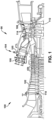
- FIG. 1 is a cross-sectional view of an illustrative machine including a turbine(s) to which teachings of the disclosure can be applied.
- a turbomachine 90 in the form of a combustion turbine or gas turbine (GT) system 100 (hereinafter, “GT system 100") is shown.
- GT system 100 includes a compressor 102 and a combustor 104.
- Combustor 104 includes a combustion region 105 and a fuel nozzle section 106.
- GT system 100 also includes a turbine 108 and a common compressor/turbine shaft 110 (hereinafter referred to as "rotor 110").
- rotor 110 common compressor/turbine shaft 110
- GT system 100 may be, for example, a 7HA.03 engine, commercially available from General Electric Company, Greenville, S.C.
- the present disclosure is not limited to any one particular GT system and may be implemented in connection with other engines including, for example, the other HA, F, B, LM, GT, TM and E-class engine models of General Electric Company and engine models of other companies.
- teachings of the disclosure are not necessarily applicable to only a turbine in a GT system and may be applied to practically any type of industrial machine or other turbine, e.g., steam turbines, jet engines, compressors (as in FIG. 1 ), turbofans, turbochargers, etc.
- turbine 108 of GT system 100 is merely for descriptive purposes and is not limiting.
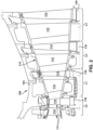
- FIG. 2 shows a cross-sectional view of an illustrative portion of turbine 108.
- turbine 108 includes four stages L0-L3 that may be used with GT system 100 in FIG. 1 .
- the four stages are referred to as L0, L1, L2, and L3.
- Stage L0 is the first stage and is the smallest (in a radial direction) of the four stages.
- Stage L1 is the second stage and is disposed adjacent the first stage L0 in an axial direction.
- Stage L2 is the third stage and is disposed adjacent the second stage L1 in an axial direction.
- Stage L3 is the fourth, last stage and is the largest (in a radial direction). It is to be understood that four stages are shown as one example only, and each turbine may have more or less than four stages.
- a turbine component 111 that teachings of the disclosure can be applied to may be provides as a turbine stationary nozzle 112 or rotating blade 114.
- the teachings of the disclosure can be applied to a variety of other turbine parts also.
- a plurality of stationary turbine vanes or nozzles 112 (hereafter “nozzle 112,” or “nozzles 112”) may cooperate with a plurality of rotating turbine blades 114 (hereafter “blade 114,” or “blades 114”) to form each stage L0-L3 of turbine 108 and to define a portion of a working fluid path through turbine 108. Blades 114 in each stage are coupled to rotor 110 ( FIG.
- a static nozzle section 115 includes a plurality of nozzles 112 mounted to a casing 124 and circumferentially spaced around rotor 110 ( FIG. 1 ). It is recognized that blades 114 rotate with rotor 110 ( FIG. 1 ) and thus experience centrifugal force, while nozzles 112 are static.
- the pressurized air is supplied to fuel nozzle section 106 that is integral to combustor 104.
- Fuel nozzle section 106 is in flow communication with combustion region 105.
- Fuel nozzle section 106 is also in flow communication with a fuel source (not shown in FIG. 1 ) and channels fuel and air to combustion region 105.
- Combustor 104 ignites and combusts fuel to produce combustion gases.
- Combustor 104 is in flow communication with turbine 108, within which thermal energy from the combustion gas stream is converted to mechanical rotational energy by directing the combusted fuel (e.g., working fluid) into the working fluid path to turn blades 114.
- Turbine 108 is rotatably coupled to and drives rotor 110.
- Compressor 102 may also be rotatably coupled to rotor 110. At least one end of rotor 110 may extend axially away from compressor 102 or turbine 108 and may be attached to a load or machinery (not shown), such as, but not limited to, a generator, a load compressor, and/or another turbine.
- FIGS. 3 and 4 show perspective views, respectively, of a (stationary) nozzle 112 and a (rotating) blade 114, of the type in which embodiments of a vibration dampening system 120 of the present disclosure may be employed.
- FIGS. 5 and 6 show schematic cross-sectional views of a nozzle 112 or blade 114 including vibration dampening system 120, according to various embodiments of the disclosure.
- each turbine component e.g., nozzle 112 or blade 114
- body 128 has a base end 130, a tip end 132, and an airfoil 134 extending between base end 130 and tip end 132.
- nozzle 112 includes an outer endwall 136 at base end 130 and an inner endwall 138 at tip end 132. Outer endwall 136 couples to casing 124 ( FIG. 2 ).
- blade 114 includes a dovetail 140 at base end 130 by which blade 114 attaches to a rotor wheel 116 ( FIG. 2 ) of rotor 110 ( FIG.
- Base end 130 of blade 114 may further include a shank 142 that extends between dovetail 140 and a platform 146.
- Platform 146 is disposed at the junction of airfoil 134 and shank 142 and defines a portion of the inboard boundary of the working fluid path ( FIG. 2 ) through turbine 108.
- airfoil 134 in nozzle 112 and blade 114 is the active component of the nozzle 112 or blade 114 that intercepts the flow of working fluid and, in the case of blades 114, induces rotor 110 ( FIG. 1 ) to rotate. It will be seen that airfoil 134 of nozzle 112 and blade 114 include a concave pressure side (PS) outer sidewall 150 and a circumferentially or laterally opposite convex suction side (SS) outer sidewall 152 extending axially between opposite leading and trailing edges 154, 156, respectively.
- PS concave pressure side
- SS convex suction side
- Sidewalls 150 and 152 also extend in the radial direction from base end 130 (i.e., outer endwall 136 for nozzle 112 and platform 146 for blade 114) to tip end 132 (i.e., inner endwall 138 for nozzle 112 and a tip end 158 for blade 114).
- blade 114 does not include a tip shroud; however, teachings of the disclosure are equally applicable to a blade including a tip shroud at tip end 158.
- Nozzle 112 and blade 114 shown in FIGS. 3-4 are illustrative only, and the teachings of the disclosure can be applied to a wide variety of nozzles and blades, among other turbine components.
- nozzles 112 or blades 114 may be excited into vibration by a number of different forcing functions. For example, variations in working fluid temperature, pressure, and/or density can excite vibrations throughout the rotor assembly, especially within the airfoils and/or tips of the blades 114 or nozzles 112. Gas exiting upstream of the turbine and/or compressor sections in a periodic (or "pulsating") manner can also excite undesirable vibrations.
- Embodiments of the present disclosure reduce the vibration of a stationary nozzle 112 or rotating turbine blade 114 without significant change of nozzle or blade design.
- Other turbine components 111 may also experience similar vibrations and can benefit from the teachings of the disclosure.
- FIGS. 5 and 6 each show a schematic cross-sectional view of a turbine component 111, e.g., a turbine nozzle 112 or blade 114, including vibration dampening system 120 according to embodiments of the disclosure.
- Nozzle 112 in the schematic cross-sectional views of FIGS. 5-6 is shown flipped vertically compared to that shown in FIG. 3 and without inner endwall 138, for ease of description. It should be understood that references to base end 130 and tip end 132 may be reversed for nozzle 112, as compared to blade 114.
- Vibration dampening system 120 is for dampening vibrations in body 128 of turbine component 111 and is configured to be installed in a body opening or internal opening 160 in body 128.
- Vibration dampening system 120 for turbine component 111 may also include a body opening or internal opening 160 extending through body 128 of turbine component 111.
- body opening 160 extends at least partially between tip end 132 and base end 130 thereof and through airfoil 134.
- Body opening 160 may extend part of the distance between base end 130 and tip end 132, or it may extend through one or more of base end 130 or tip end 132.
- Body opening 160 may be defined in any part of any structure of body 128.
- body opening 160 may be defined as an internal cavity in the partition wall in body 128.
- Body opening 160 generally extends radially in body 128, but this may not be necessary in all cases. For example, some angling, and perhaps curving, of body opening 160 relative to a radial extent of body 128 is possible, and/or body opening 160 may not extend radially in all turbine components 111.
- Body opening 160 has an inner surface 162.
- body opening 160 may originate at base end 130 of nozzle 112 or blade 114, or, as shown in FIG. 6 , it may originate at tip end 132 of nozzle 112 or blade 114. More particularly, as shown in FIG. 5 , body opening 160 may be open in base end 130 and terminate in tip end 132, or, as shown in FIG. 6 , it may be open in tip end 132 and terminate in base end 130. The open end may assist in assembly of vibration dampening system 120 in nozzle 112 or blade 114 and may allow retrofitting of the system into an existing nozzle or blade. Where body opening 160 extends through base end 130 as shown in FIG. 5 , a closure member 164 for closing body opening 160 may be provided.
- a closure member 166 for body opening 160 may be provided.
- closure members 164, 166 prevent removal of vibration dampening system 120 from body opening 160.
- Closure members 164, 166 may also optionally be used to mount a resonant-tuned elongated body 190 according to embodiments of the disclosure.
- FIGS. 5 and 6 drawing schematic cross-sectional format will be used periodically in the drawings to illustrate how certain vibration dampening systems 120 can be used in a nozzle 112 or blade 114 facing in different radial directions. As will be further described, some forms of vibration dampening systems 120 are only applicable to turbine blades 114 or other turbine components 111 that experience centrifugal force, i.e., in a radial outward direction.
- Vibration dampening system 120 for turbine component 111 may include one or more damper elements 174 in body opening 160.
- Damper element(s) 174 can be stacked together.
- damper element(s) 174 can take a large variety of forms.
- damper element(s) 174 in body opening 160 may include a first plurality of stacked washers 176 and a second plurality of stacked washers 178.
- Each "washer” includes a plate member having an opening 192 therein. Washers 176, 178 may have circular outer edges, but this is not necessary in all cases.
- Vibration dampening system 120 for turbine component 111 also includes a resonant-tuned elongated body 190 extending through an opening 192 in damper element(s) 174 in body opening 160.
- Resonant-tuned elongated body 190 (hereafter "RTE body 190") is configured to resonate at predefined resonant frequency.
- the "predefined resonant frequency" as used herein may be any frequency configured to address a frequency of concern in turbine component 111.
- the predefined resonant frequency may be, for example, a resonant frequency of turbine component 111 at body opening 160 during operation of turbine component 111, or a resonant frequency known to influence turbine component 111 at body opening 160 during operation.
- the latter example may include but is not limited to a frequency just above or below the resonant frequency of turbine component 111 at body opening 160 during operation.
- RTE body 190 generates a force F against damper element(s) 174 in body opening 160.
- Body opening 160 i.e., inner surface 162
- RTE body 190 has an outer dimension OD1.
- each of damper element(s) 174 in body opening 160 has a surface 194 in contact with at least one of body opening 160 and RTE body 190, respectively.
- first plurality of stacked washers 176 has a first outer dimension OD2 and second plurality of stacked washers 178 has a second outer dimension OD3.
- First outer dimension OD2 and second outer dimension OD3 are different.
- First plurality of stacked washers 176 also has an inner dimension ID2 and second plurality of stacked washers 178 has an inner dimension ID3.
- Inner dimension ID2 of first plurality of stacked washer 176 and inner dimension ID3 of second plurality of stacked washers 178 are different.
- first outer dimension OD2 of first plurality of stacked washers 176 matches inner dimension ID1 of body opening 160, i.e., of inner surface 162 thereof, and second outer dimension OD3 of second plurality of stacked washers 178 is smaller than inner dimension ID1 of body opening 160.
- surface 194 of first plurality of stacked washers 176 contacts body opening 160.
- Inner dimension ID2 of first plurality of stacked washers 176 is larger than outer dimension OD1 of RTE body 190
- inner dimension ID3 of second plurality of stacked washer 178 matches outer dimension OD1 of RTE body 190. In this manner, an inner surface 196 of second plurality of stacked washers 178 contacts RTE body 190.
- each damper element(s) 174 in body opening 160 has surface 194 or 196 in contact with at least one of body opening 160 and RTE body 190, respectively.
- “matches” means the stated dimensions are close to the same size or slightly smaller or larger to allow installation of the respective parts, e.g., washers 176 in body opening 160, or RTE body 190 through inner surface 196 of washers 178.
- the extent of “slightly smaller or larger” may vary depending on the tolerances required for installation.
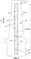
- RTE body 190 can be configured to match the predefined resonant frequency in a number of ways. More particularly, RTE body 190 includes at least one of the following characteristics thereof selected to generate the predefined resonant frequency in RTE body 190 during operation of turbine component 111: a material (e.g., mass, flex, hardness, etc.) and a length L ( FIGS. 5-6 ). In addition, at least one outer dimension of RTE body 190 can be adjusted. In FIGS. 5-7 , RTE body 190 has a single outer dimension OD 1. However, as shown in FIG. 8 , RTE body 190 may have sections 200 having different outer dimensions OD4, OD5.
- RTE body 190 may have any number of sections 200 having different outer dimensions. As will be described further herein, sections 200 of different outer dimensions may also be used to retain damper elements 174 relative to RTE body 190.
- an outer dimension taper along a length L of RTE body 190 may be selected to match the predefined resonant frequency of RTE body 190 with a resonant frequency of turbine component 111 at body opening 160.
- an outer dimension OD6 of RTE body190 at one location is larger than an outer dimension OD7 of RTE 190 at another location such that the body tapers from one location to another, i.e., it is frusto-conical.
- the outer dimensions and/or the angle of taper can be adjusted to obtain the desire predefined resonant frequency.
- RTE body 190 may also include one or more hollow sections (two shown 210, 212 each with a wall thickness (T1, T2, respectively) at at least one location configured to adjust the resonant frequency of RTE body 190. That is, RTE body 190 may include one or more hollow sections 210, 212 with different wall thicknesses T1, T2. In another embodiment, shown in FIG. 10B , RTE body 190 may simply be tubular with a uniform wall thickness T3.
- At least one attachment type to turbine component 111 can be adjusted.
- RTE body 190 is fixedly coupled to base end 130 in FIG. 5 or at tip end 132 in FIG. 6 , and an opposing end of RTE body 190 is free to vibrate.
- RTE body 190 may also be fixed at both ends.
- the type of attachment may include threaded fasteners, welding, clamping or other types of attachment, and may be selected to control the predefined resonant frequency.
- the length of RTE body 190 used in the attachment can also vary to control resonant frequency.
- RTE body 190 has one attachment location to turbine component 111.
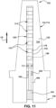
- RTE body 190 may have more than one (additional) attachment location 220 with turbine component 111 to control its resonant frequency.
- RTE body 190 includes an attachment location 220, i.e., pinned location, between its ends to define the predefined resonant frequency.
- the form of attachment at location 220 can take any form that affects the vibration frequency of RTE body 190, i.e., a simple contact, fixed attachment (e.g., fastener, weld, etc.), among other options.
- Damper element(s) 174 can take a large variety of forms other than shown in FIGS. 5-11 .
- FIGS. 12-32 show alternative forms of damper element(s) 174.
- one or more damper elements 174 in body opening 160 include a plurality of damper elements 174 stacked together along at least some portion of RTE body 190.
- FIGS. 5-7 show embodiments using a plurality of stacked damper elements 174 using different dimension stacked washers, i.e., damper element(s) 174 in body opening 160 may include a first plurality of stacked washers 176 and a second plurality of stacked washers 178.
- the one or more damper elements 174 in body opening 160 may be selected from a group comprising: a damper pin, a damper element having flexible legs (see FIGS. 21-22 ), a spring-suspended damper element (see FIGS. 17-20 ), a nested damper pin (see FIGS. 23-24 ), a plate member with an opening (e.g., flat or curved washers, see FIGS. 5-7 , 12-15 ), a helical metal ribbon spring (see FIG. 16 ), and a wire mesh (see FIGS. 25-32 ).
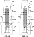
- FIGS. 12 shows a schematic cross-sectional view of turbine component 111 including a vibration dampening system 120 using an RTE body 190 with stacked damper elements 174 in the form of stacked plate members 230 with openings 232 therein, i.e., washers.
- Plate members 230 in FIGS 12-15 are similar to those in FIGS. 5-7 except plate members 230 are concave/convex and have the same outer dimension OD7 that matches an inner dimension ID1 of body opening 160).
- Plurality of stacked plate member(s) 230 may be retained in position or limited in movement. For example, retention members 234 ( FIG. 13 ), 236 ( FIG. 14 ), 242 ( FIG.
- RTE body 190 may be used to restrain plate members 230.
- retention member 234, 236, 242 on RTE body 190 may be used to retain plate members 230 relative to a length of RTE body 190 and/or control the predefined resonant frequency of RTE body 190 in an operative state in body opening 160 of turbine component 111.
- a compression member 238, e.g., a spring or other flexible member or a weight, may be used to apply pressure to plate members 230.
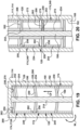
- FIG. 15 shows a cross-sectional view of another embodiment in which plurality of stacked plate members 230 are separated into at least two groups 240. In FIG.
- a retention member 242 on RTE body 190 engages with an endmost plate member 230X of each group 240A-C to prevent the respective group from moving relative to a length of RTE body 190.
- End 244 of body opening 160 may retain group 240A closest to tip end 132, or another retainer (similar to 242 but not shown) can be used.
- Any number of groups 240 with each group including any number of plate members 230 can be used to provide the desired vibration dampening.
- FIG. 16 shows a schematic cross-sectional view of turbine component 111 including a vibration dampening system 120 using an RTE body 190 with a damper element 174 in the form of a helical metal ribbon spring 246 with opening 248 therein.
- Helical metal ribbon spring 246 may have a uniform outer dimension OD8 that matches inner dimension ID1 of body opening 160.
- FIGS. 17-20 show schematic cross-sectional views of turbine component 111, such as a turbine blade 114, including a vibration dampening system 120 using an RTE body 190 with stacked damper elements 174 that include spring-suspended bearing members 249.
- FIG. 19 shows an enlarged cross-sectional view of spring-suspended bear members 249.
- FIG. 20 shows an enlarged cross-sectional view of spring-suspended bear members 249 according to an alternative embodiments.
- FIGS. 17 and 18 show damper elements 174 may include RTE body 190 having an axially fixed position within body opening 160.
- spring-suspended bearing member 249 includes a disc spring 250 fixedly coupled to RTE body 190 at a center 252 of disc spring 250 and a bearing member 254 coupled to a first side 256 of disc spring 250 at an outer portion thereof, i.e., relative to center 252.
- Bearing member 254 may include any element capable of frictionally engaging a first bearing surface 258 to dampen vibration. As will be described, a location of first bearing surface 258 can vary depending on the particular damper element 174. In FIGS.
- disc spring 250 includes any form of disc spring, also known alternatively as, for example: a Belleville washer, Belleville spring, cupped spring washer, coned-disc spring, conical spring washer, etc. While shown in a planar, initial configuration, disc spring 250 can also have any frustoconical arrangement, among other shapes. Disc spring 250 can have any form capable of providing a desired spring action or spring constant.
- Disc spring 250 has center 252 coupled to RTE body 190, and an outer portion 260 having a first side 256 coupled to bearing member 254. Disc spring 250 also includes a second side 262 opposite first side 256. Center 252 of disc spring 250 may be fixedly coupled to RTE body 190 of in any now known or later developed fashion. For example, where center 252 includes an opening, center 252 of disc spring 252 may be welded or brazed to RTE body 190. Alternatively, disc spring 250 and RTE body 190 may be additively manufactured as integral parts, along with bearing member 254. Bearing member 254 is coupled to first side 256 of disc spring 250 and extends radially distal from first side 256 of disc spring 250, i.e., relative to a turbine axis.
- bearing member 254 may extend radially inward, i.e., toward base end 130 of blade 114 from first side 256 of disc spring 250.
- FIG. 18 shows a cross-sectional view of spring-suspended bearing member 249 in which bearing member 254 also extends radially distal from first side 256 of disc spring 250, but radially outward from first side 256 of disc spring 250, i.e., toward tip end 132 of blade 114.
- Disc spring 250 can have a thickness that is different than bearing member 254. The thickness of disc spring 250 may vary over its radial extent to provide any desired spring action or spring constant.
- FIG. 19 shows damper elements 174 in an operative position in which disc springs 250 are in an elastically extended state under influence of a centrifugal force CF caused by rotating blade 114 rotating above a predefined rotational speed.
- disc springs 250 are elastically extended (radially outward toward tip end 132 ( FIGS. 17-18 )) at outer portions 260 thereof, causing an gap between disc springs 250 (see FIGS. 17-18 ) to disappear, and causing bearing member 254 to frictionally engage first bearing surface 258 to dampen vibration.
- first bearing surface 258 may be second side 262 of an adjacent damper element's disc spring 250.
- first bearing surface 258 includes second side 262 of disc spring 250 opposite from first side 256.
- end surface 266 of bearing member 254 frictionally engages second side 262 of disc spring 250 of an adjacent damper element 174 to dampen vibration.
- second side 262 of its disc spring 250 frictionally engages a first bearing surface 258 that is part of an end surface 270 of body opening 160, i.e., a radially outer end surface 270.
- first bearing surface 258 may be located on one of: second side 262 of disc spring 250 and end surface 270 of body opening 160 in rotating blade 114.
- An “elastically extended state” indicates disc spring 250 has extended sufficiently to have bearing member 254 frictionally engaging first bearing surface 258, but may not be fully extended due to the travel distance of bearing member 254 being limited by first bearing surface 258.
- Disc spring 250 may also be used to control the predefined resonant frequency of RTE body 190, e.g., by providing a different outer dimension and/or attachment/pinning location between the ends of RTE body 190.
- FIG. 20 shows a cross-sectional view of another embodiment in which disc spring 250 can be, but is not necessarily, fixedly coupled to RTE body 190.
- RTE body 190 may further includes a positioning collar 272, which may be concentrically arranged with RTE body 190. Positioning collar 272 thus may axially position respective disc springs 250 relative to RTE body 190 without disc springs 250 being fixedly coupled to RTE body 190.
- Positioning collar 272 can be a tubular member that slides onto RTE body 190, or can be integral with RTE body 190.
- positioning collar 272 may abut second side 262 of disc springs 250 adjacent center 252 to position disc springs 250 and to provide a surface upon which disc springs 250 can elastically extend. Positioning collar 272 may also be used to control the predefined resonant frequency of RTE body 190, e.g., by providing a different outer dimension.
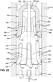
- FIGS. 21-22 shows a side, partially cross-sectional view of vibration dampening system 120 including a plurality of stacked damper elements 174 including flexible legs, according to other embodiments of the disclosure.
- FIG. 21 shows damper elements 174 in a first, relaxed position
- FIG. 22 shows damper elements 174 in a second, operative position with flexible legs frictionally engaged with body opening 160.
- damper elements 174 includes a head member 300 having an at least partially ramped surface 302.
- Damper element 174 also includes a plurality of flexible and expandable legs 304 (hereafter simply "flexible legs 304") extending from head member 300.
- Each flexible leg 304 includes a radially extending body section 306 (relative to blade 114) having an end section 308.
- End sections 308 have an outer end surface 310 and an inner end surface 312.
- head member 172 engages with flexible legs 304 of another, adjacent damper element 174 to cause flexible legs 304 thereof to flex outwardly and frictionally engage with inner surface 162 of body opening 160 under influence of a centrifugal force CF caused by rotation of rotating blade 114 at higher than a predefined rotational speed to dampen vibration.
- Each flexible leg 304 can have any structure capable of permitting it to flex outwardly such that outer end surfaces 310 can frictionally engage with inner surface 162 of body opening 160 in blade 114.
- adjacent radially extending body sections 306 hereafter "body sections 306" of flexible legs 304 define a slot 314 therebetween.
- Slots 314 may terminate at head member 300.
- Slots 314 may have a rounded radially outer extent 316, e.g., U-shaped; however, other shapes are also possible, e.g., V-shaped, cathedral-shaped, etc. Any number of flexible legs 304 can be provided on each damper element 174.
- each damper element 174 between three (3) and six (6) flexible legs 304 are used on each damper element 174, but other numbers are also possible.
- body sections 306 can have alternative structures to aid and/or control flexing thereof such as but not limited to: wider or thinner sections, curvature, voids, etc.
- head member 300 has at least partially ramped surface 302.
- At least partially ramped surface 302 may extend all the way around it, e.g., as a solid circular surface, or partially around head member 300, i.e., with breaks or open areas between similarly ramped surfaces.
- Ramped surface(s) 302 may have an angle ⁇ in a range between 25° and 55° degrees relative to inner surface 162 of body opening 160.
- body opening 160 may extend generally radially in body 128 of blade 114.
- Inner end surfaces 312 of plurality of flexible legs 304 are configured to receive ramped surface 302 of head member 300 of an adjacent damper element 174, i.e., engage and move under influence of ramped surface 302.
- Inner end surfaces 312 of flexible legs 304 may have an angle ⁇ in a range between 25° and 55° degrees relative to inner surface 162 of body opening 160. Angle ⁇ and angle ⁇ may be the same, but this is not necessary in all cases, so long as head member 300 can force legs 304 of an adjacent damper element 174 outwardly toward inner surface 162 of body opening 160.
- head member 300 of an adjacent damper element 174 can force outer end surfaces 310 of flexible legs 304 into frictional engagement with inner surface 162 of body opening 160 to dampen vibration when a particular centrifugal force CF is applied based on a predetermined rotational speed of blade 114.
- head member 300 and, collectively, body sections 306 of flexible legs 304 each have a first outer dimension OD9.
- Outer end surfaces 310 of flexible legs 304 collectively define a second outer dimension OD10 that is larger than first outer dimension OD9.
- head member 300 and body sections 306 have a smaller outer dimension OD9 than outer end surfaces 310 of flexible legs 304, i.e., OD10.
- body sections 306 and head member 300 may have different outer dimensions so long as they are both smaller than the outer dimension OD10 of outer end surfaces 310. As shown in FIGS.
- second outer dimension OD10 of outer end surfaces 310 is matches inner dimension ID1 of body opening 160 whereby, in a relaxed state, flexible legs 304 pass freely within body opening 160.
- outer end surfaces 310 of each flexible leg 304 may be parallel to inner surface 162 of body opening 160 in a relaxed state of the plurality of flexible legs 304.
- outer end surfaces 310 of each flexible leg 304 may be non-parallel to inner surface 162 of body opening 160 in a relaxed state of the plurality of flexible legs 304, but not more than +/- 5°.
- damper elements 174 can be easily inserted into body opening 160 singularly or in a pre-stacked fashion without outer end surfaces 310 of end sections 308 thereof interfering with the insertion.
- damper elements 174 include an opening 320 defined through a center of head member 300, and RTE body 190 extends through opening 320 in head member 300. Opening 320 and RTE body 190 can have any mating cross-sectional shape such as circular, oblong or oval, polygonal, etc.
- a single RTE body 190 can extend through each damper element 174 in a stack of damper elements 174 in vibration dampening system 120.
- RTE body 190 is configured to resonate at the predefined resonant frequency, e.g., a same frequency as rotating blade 114 at body opening 160, whereby RTE body 190 generates a force against damper element(s) 174.
- RTE body 190 can be configured to resonate at the predefined resonant frequency, e.g., same resonant frequency as rotating blade 114, by controlling, among other factors, its mass, flex, hardness, dimension and length.
- RTE body 190 slides freely in opening 320 but has close clearance therewith such that movement of RTE body 190 caused by vibration of blade 114 will physically impact an inside of opening 320, causing the respective damper element 174 to move. In this manner, RTE body 190 can reduce the likelihood that damper element(s) 174 becoming stuck against inner surface 162 of body opening 160 or to each other.
- vibration dampening system 120 as shown in FIGS. 21-22 may further include a radially outer retainer element fixed to RTE body 190 to retain plurality of stacked damper elements 174 on RTE body 190.
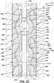
- FIG. 23 shows a cross-sectional enlarged view of vibration dampening system 120 including damper elements 174, each including an outer body and an inner body, around RTE body 190, according to embodiments of the disclosure.
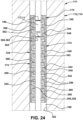
- FIG. 24 shows a cross-sectional view of vibration dampening system 120 including damper elements 174, each including an outer body and an inner body, around RTE body 190, according to other embodiments of the disclosure.
- Each damper element 174 may include an outer body 340 having an inner opening 342.
- Outer body 340 may also include a first end surface 344 and an opposing second end surface 346.
- Outer body 340 may have an outer surface 348 having a shape and dimension to match body opening 160, e.g., fit within body opening 160.
- body opening 160 has inner surface 162 having inner dimension ID1.
- Each outer body 340 has an outer dimension OD11 sized to frictionally engage inner dimension ID1 of body opening 160 to dampen vibration during motion of turbine component 111, e.g., nozzle 112 or blade 114. That is, outer dimension OD11 of outer body 340 of each damper element 174 rubs against inner surface 162 of body opening 160 to dampen vibration, e.g., during movement of airfoil 134 ( FIGS. 3-4 ) of nozzle 112 or blade 114.
- inner dimension ID1 and outer dimension OD11 are sized to allow damper elements 174 to be positioned in body opening 160, i.e., they match as defined herein.
- a difference between outer dimension OD11 of damper elements 174 and inner dimension ID1 of inner surface 162 of body opening 160 may be in a range of approximately 0.04-0.06 millimeters (mm), which allows insertion of damper elements 174 but frictional engagement during use and relative movement of airfoil 134 ( FIGS. 3-4 ) of nozzle 112 or blade 114.
- First end surface 344 and second end surface 346 of outer body 340 are complementary of one another, i.e., they fit together, so they can frictionally engage one another.
- first end surface 344 of outer body 340 is at least partially concave
- second end surface 346 of outer body 340 is at least partially convex. In this manner, first end surface 344 and second end surface 346 of adjacent damper elements 174 can frictionally engage and rotationally move relative to one another as nozzle 112 or blade 114 moves.
- first end surface 344 of outer body 340 is planar, and second end surface 346 of outer body 340 is also planar.
- first end surface 344 and second end surface 346 of adjacent damper elements 174 can frictionally engage and slidingly move relative to one another as turbine component 111, e.g., nozzle 112 or blade 114, moves.
- Other complementary shapes for end surfaces 344, 346 are also possible.
- Outer body 340 also includes a central opening 350 (part of inner opening 342) extending through first end surface 344 and second end surface 346. As will be described, central opening 350 is configured to allow RTE body 190 to extend therethrough and to allow pivoting movement of an inner body 360 within outer body 340.
- Each damper element 174 may also include an inner body 360 nested and movable within inner opening 342 of outer body 340.
- Inner body 360 has a central opening 362 including a first portion 364 configured to engage RTE body 190 therein.
- Inner body 360 also includes an outer surface 366 configured to frictionally engage a portion 368 of inner opening 342 of outer body 340.
- Inner body 360 and inner opening 342 of outer body 340 may take a variety of forms. In certain embodiments, shown in FIG. 23 , outer surface 366 of inner body 360 may have a pear shape. More particularly, outer surface 366 of inner body 360 may include a bulbous base portion 370 and a narrower neck portion 372.
- narrower neck portion 372 includes first portion 364 of central opening 362 of inner body 360.
- First portion 364 has an inner dimension ID2 configured to engage with an outer dimension OD12 of RTE body 190.
- Inner dimension ID2 allows sliding engagement with outer dimension OD12 of RTE body 190.
- first portion 364 of central opening 362 has sufficient (radial) length to mandate inner body 360 moves with RTE body 190, e.g., it tilts, pivot or otherwise moves under the influence of RTE body 190. It can also control the predefined resonant frequency of RTE body 190.
- Bulbous base portion 370 includes a second portion 378 of central opening 362 of inner body 360 that has a larger inner dimension ID3 than inner dimension ID2 of first portion 364 of central opening 362 of inner body 360.
- second portion 378 of central opening 362 of inner body 360 is distanced from RTE body 190.
- Central opening 350 of outer body 340 is also distanced from inner body 360 of damper element 174 and RTE body 190 at both end surfaces 344, 346.
- second portion 378 of central opening 362 of inner body 360 allows pivoting movement of inner body 360 within outer body 340 under the influence of bending and/or moving of RTE body 190 as turbine component 111, i.e., nozzle 112 or blade 114, vibrate.
- Inner opening 342 of outer body 340 has a shape configured to receive the pear shape of outer surface 366 of inner body 360 and allow frictional engagement between inner body 360 and outer body 340 under the influence of RTE body 190 on inner body 360.
- RTE body 190 moves, e.g., bends with airfoil 134 during operation thereof, it imparts motion to inner body 360 via first portion 364 of central opening 362 of inner body 360, which can cause inner body 360 to rock or tilt relative to outer body 340.
- inner body 360 and outer body 340 frictionally engage one another to dampen vibration.
- the frictional engagement can occur anywhere along outer surface 366 of inner body 360 and inner opening 342 of outer body 340.
- frictional engagement may occur near an upper portion (as illustrated on the page of FIG. 23 ) of bulbous base portion 370 and outer surface 366 of inner body 360 and a corner 380 of inner opening 342 of outer body 340 where it enlarges to match the pear shape of inner body 360. Frictional engagement can also occur anywhere along outer surface 366 of bulbous base portion 370 and/or narrower neck portion 372.
- inner body 360 includes a planar washer member 382.
- Planar washer member 382 may include any plate having a central opening 384 therein.
- Central opening 384 of planar washer member 382 has an inner dimension ID4 configured to engage with outer dimension OD13 of RTE body 190, i.e., sliding engagement but forcing lateral pivoting with RTE body 190.
- Inner dimension ID4 allows sliding engagement with outer dimension OD13 of RTE body 190.
- planar washer member 382 has sufficient (radial) length to mandate that it moves with RTE body 190, e.g., it tilts, pivot or otherwise moves under the influence of RTE body 190. In this manner, inner body 360 (washer member 382) moves with RTE body 190 as turbine component 111, e.g., nozzle 112 or blade 114, move.
- outer body 340 includes a cup member 386 providing inner opening 342, which is configured to receive planar washer member 382.
- cup member 386 includes a base 388 and a tubular side 390 that collectively surround and encapsulate planar washer member 382 therein with an adjacent damper element 174.
- Outer body 340 also includes first end surface 344 and second end surface 346 (surfaces of cup member 386), which are planar as previously noted.
- Inner body 360 and, more particularly, cup member 386 also includes central opening 392 (part of inner opening 342) through which RTE body 190 may freely pass.
- Inner body 360, including planar washer member 382 may frictionally engage with any part of inner opening 342 of outer body 340 to dampen vibration.
- Planar end surfaces 344, 346 of adjacent damper elements 174 also frictionally engage with one another to dampen vibrations.
- Outer body 340 i.e., outer surface of cup member 386) is sized to slide into body opening 160, but also may frictionally engage with inner surface 162 of body opening 160 to dampen vibration during operation of nozzle 112 or blade 114, i.e., their respective dimensions match.
- RTE body 190 may also deflect during operation of nozzle 112 or blade 114 to dampen vibration. Any number of stacked damper elements 174 as in FIG. 24 may be employed in vibration dampening system 120.
- vibration dampening system 120 may include RTE body 190 extending within and fixed relative to body opening 160.
- RTE body 190 extends through inner opening 342 of outer body 340 including central opening in end surfaces 344, 346.
- RTE body 190 also extends through second portion 378 of central opening 362 of inner body 360, and is slidingly engaged by first portion 364 of central opening 362 of inner body 360.
- RTE body 190 extends in body opening 160 of turbine component 111, e.g., nozzle 112 or blade 114, and is engaged within first portion 364 of central opening 362 of each inner body 360 of the plurality of stacked damper elements 174.
- first portion 364 of central opening 362 of inner body 360 and RTE body 190 are sized and shaped such that inner body 360 slides freely on RTE body 190, but inner body 360 can be moved as RTE body 190 dictates.
- each damper element 174 may experience different movement by RTE body 190 and provide different vibration dampening through frictional engagement of outer body 340 and inner body 360.
- Vibration dampening system 120 in FIG. 24 operates in a similar fashion.
- the various shapes and sizes of outer body 340 and inner body 360 may also be used to control the predefined resonant frequency of RTE body 190.
- FIG. 25 shows a schematic cross-sectional view of vibration dampening system 120 including an RTE body 190 used with damper elements 174 in the form of wire mesh members 400.
- FIG. 25 shows RTE body 190 attached at tip end 130 of turbine component 111 and with a number of wire mesh members 400.
- Retention members 402 may be located along RTE body 190 to hold wire mesh members 400 and control the predefined resonant frequency of RTE body 190.
- FIG. 26 shows a schematic cross-sectional view of vibration dampening system 120 including an RTE body 190 used with damper elements 174 in the form of wire mesh members 400.
- FIG. 26 shows RTE body 190 attached at base end 132 of turbine component 111 and with a single mesh member 400.
- Retention member 402 may be located along RTE body 190 to hold wire mesh member 400 and control the predefined resonant frequency of RTE body 190.
- a vibration dampening system 120 may also optionally include a compression member 404 movable along RTE body 190 to compress wire mesh member(s) 400 against retention member 402 during operation of turbine component 111, i.e., beyond the compression provided by centrifugal force of the rotating blades 114.
- RTE bodies 190 include at least one first RTE body 190A having second end 410A thereof fixed relative to tip end 132 of body 128, and a first, free end 412A thereof extending towards base end 130.
- RTE bodies 190 also include at least one second RTE body 190B having a second end 412B thereof fixed relative to base end 130 of body 128, and a first, free end 410B thereof extending towards tip end 132. Any number of each RTE bodies 190A, 190B may be employed.
- Wire mesh member(s) 400 surround both types of RTE bodies 190A, 190B to force each RTE body 190A, 190B into contact with at least one other RTE body 190A, 190B during operation of turbine component 111. In this manner, each RTE body 190A, 190B is in contact with at least one other RTE body 190A fixed to tip end 132 and/or at least one other RTE body 190B fixed to base end 130.
- FIGS. 28 and 29 show cross-sectional views along view line A-A in FIG. 27 of various embodiments.
- FIG. 28 shows a cross-sectional view of an embodiment including one RTE body 190A, and one RTE body 190B.
- FIG. 29 shows a cross-sectional view including a plurality of (e.g., two) RTE bodies 190A, and a plurality of (e.g., two) RTE bodies 190B. Any number of each type of RTE body 190A, 190B may be used so long as they can be surrounded by wire mesh member(s) 400 to allow limited movement within body opening 160, e.g., circumferentially (into and out of page) and radially (up and down page).
- a retention member 402 may be provided to retain wire mesh member(s) 400 relative to a length of RTE bodies 190, 190A, 190B.
- retention member 402 may be positioned on one or more of RTE bodies 190A and/or 190B, as in FIG. 25 , to prevent wire mesh member(s) 400 from moving relative to a length of RTE bodies 190, e.g., because of centrifugal or vibrational forces of blades 114 or vibrational forces of nozzle 112.
- retention member 402 may be provided by a closed end 414 of body opening 160 at tip end 132 in body 128.
- fixed end 410A of RTE body(ies) 190A may be fixed by being threaded or otherwise fastened into closed end 414 of body opening 160.
- fixed end 412B of RTE body(ies) 190B may be similarly fixed in base end 130.
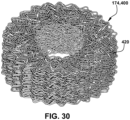
- FIG. 30 shows a perspective view of an illustrative wire mesh member 400.
- Wire mesh member 400 includes any now known or later developed wire mesh dampening material suitable for restricting movement of RTE body(ies) 190.
- Wire mesh member(s) 400 may also be coated in various coating materials to alter frictional properties thereof.
- Wire mesh member 400 may be referred to as ⁇ metal rubber.
- wire mesh member(s) 400 may include a knitted wire-mesh material 418.
- FIG. 31 shows a perspective view of vibration dampening system 120 including an RTE body 190 including a retention system 420 including a number of retention members 422.
- each retention member 422 includes a protrusion 424 on RTE body 190.
- RTE body 190 also includes portions on outer surface thereof where protrusions 424 are not present.
- Protrusion(s) 424 may extend any extent around and/or along RTE body 190 to create the desired outer dimension on wire mesh member 400 and/or desired predefined resonant frequency of RTE body 190.
- protrusion(s) 424 may extend symmetrically around the full circumference of RTE body 190, although such symmetry is not required. Any number of protrusion(s) 424 may be provided on RTE body 190, e.g., one for each wire mesh member 400.
- FIG. 32 shows an assembled side view of RTE body 190 including a retention system 430 and retention member 432, according to another embodiment of the disclosure.
- each retention member 432 includes a threaded section 434 on a first portion of an outer surface of RTE body 190.
- RTE member 190 may also optionally include a non-threaded section 436 on a second portion on outer surface of RTE body 190. Where thread-free, portion 436 is provided, an inner dimension of wire mesh member 400 slides freely relative to RTE body 190. Any number of threaded sections 434 can be provided to thread into a respective number of wire mesh members 400.
- Threaded section(s) 434 may have any threading format necessary to allow threaded insertion into, and outward compression of, wire mesh member(s) 400 during assembly. Threaded section(s) 434 may extend any extent around and/or along RTE body 190 to create the desired outer dimension and/or predefined resonant frequency. Threaded section 434 may also alternatively extend an entire length of RTE body 190.
- a single body opening 160 is used in a turbine component 111.
- turbine component 111 includes first vibration dampening system 120A with a first body opening 160A and a second vibration dampening system 120B with a second body opening 160B.
- Vibration dampening systems 120A in first body opening 160A includes RTE body 190A.
- more than one vibration dampening system 120 may be used with other system(s) 120B each including one or more damper elements 174 in another respective (second) body opening 160B. Damper element(s) 174 in second body opening 160B can take any of the previously described forms.
- Vibration dampening system 120B also includes another (second) RTE body 190B extending through an opening in damper element(s) 174 in the other body opening 160B.
- Second RTE body 190B may be configured to resonate at a predefined resonant frequency, e.g., at a same frequency as turbine component 111 at second body opening 160B, that is different than the predefined resonant frequency of first RTE body 190, e.g.,.
- Second RTE body 190B generates a force against damper element(s) 174 in second body opening 160B in a similar manner as that described relative to the RTE bodies described herein.
- Each of damper element(s) 174 in second body opening 160B has a surface in contact with at least one of second body opening 160B and the other (second) RTE body 190B.
- Embodiments of the disclosure may include any turbine component 111 such as a turbine nozzle 112 or turbine blade 114. It will be recognized that those embodiments requiring centrifugal force (CF) to activate damper element(s) 174 may be employed in a turbine component 111 that rotates and experiences the centrifugal force CF, such as but not limited to a turbine blade 114.
- CF centrifugal force
- a method may include selecting a frequency of concern Fc for turbine component 111 in operation at body opening 160 defined therein.
- the frequency of concern Fc may be any frequency, typically a resonant frequency, of turbine component 111 at body opening 160 that a user may want to dampen.
- an RTE body 190 to be positioned at/in body opening 160 is configured to have a predefined resonant frequency, e.g., same as or close to the frequency of concern Fc of turbine component 11 at body opening 160.
- RTE body 190 configuring can include selecting (choosing and/or modifying) at least one of the following characteristics of RTE body 190 to generate the resonant frequency of RTE body 190 during operation of turbine component 111: a length, at least one outer dimension, an outer dimension taper along a length thereof, a wall thickness at at least one location, a material, at least one attachment location to the turbine component, at least one attachment type to the turbine component, and a number of the elongated bodies.
- RTE body 190 can dampen vibrations at a preselected frequency of concern Fc, providing customized vibration dampening at one or more particular body opening 160 locations.
- the method may further include positioning RTE body 190 through an opening in damper element(s) 174.
- This step can be performed outside of turbine component 111 and/or damper element(s) 174 can be positioned in body opening 160 and then RTE body 190 inserted through damper element(s) 174.
- RTE body 190 with damper element(s) 174 is positioned in body opening 160.
- damper element(s) 174 in body opening 160 has a surface in contact with at least one of body opening 160 and RTE body 190 allowing vibration dampening.
- the damper element(s) 174 can be selected from any form described herein, among others. In certain embodiments, shown in FIGS.
- damper element(s) 174 may include a first plurality of stacked washers 176 having first outer dimension OD2 and second plurality of stacked washers 178 having second outer dimension OD3, where OD2 ⁇ OD3.
- first outer dimension OD2 matches an inner dimension ID1 of body opening 160 (i.e., "matches” means close to same dimension or slightly smaller to allow insertion of washers 176 in body opening 160), and second outer dimension OD3 is smaller than inner dimension ID1 of body opening 160.
- First plurality of stacked washers 176 has a first inner dimension ID2 and the second plurality of stacked washers 178 has a second inner dimension ID3.
- First inner dimension ID2 is larger than outer dimension OD1 of RTE body 190 and the second inner dimension ID3 matches outer dimension OD1 of RTE body 190 (i.e., "matches” means close to same dimension or slightly larger to allow insertion of RTE body 190 into washers 178).
- Vibration dampening system 120 reduces turbine component vibration with a simple arrangement and does not add much extra mass to the turbine component 111, e.g., nozzle 112 or blade 114. Vibration dampening system 120 does not increase centrifugal force to nozzle 112 base end 130 or blade 114 tip end 132 or require a change in turbine component 111configuration. Vibration dampening system 120 allows addressing a wide variety of different vibration characteristics of turbine component and/or vibration dampening system 120 (RTE body 190 and/or dampening element(s) 174) beyond just different frequency, such as different mode shapes and/or different amplitudes.
- Vibration dampening system 120 also allows customization of RTE body 190 attachment in a wide variety of configurations such as but not limited to: “fixed-free” with one end fixed, moment allowed, no translation and no rotation; “fixed-pinned” with one end fixed, with rotation allowed, no moment and no translation; “fixed-fixed” with both ends fixed; and various configurations with attachment (pinning) in the middle of RTE body 190.
- Approximating language may be applied to modify any quantitative representation that could permissibly vary without resulting in a change in the basic function to which it is related. Accordingly, a value modified by a term or terms, such as “about,” “approximately” and “substantially,” are not to be limited to the precise value specified. In at least some instances, the approximating language may correspond to the precision of an instrument for measuring the value.
- range limitations may be combined and/or interchanged; such ranges are identified and include all the sub-ranges contained therein unless context or language indicates otherwise. "Approximately” or “about,” as applied to a particular value of a range, applies to both end values and, unless otherwise dependent on the precision of the instrument measuring the value, may indicate +/- 10% of the stated value(s).
Landscapes
- Engineering & Computer Science (AREA)
- Mechanical Engineering (AREA)
- General Engineering & Computer Science (AREA)
- Turbine Rotor Nozzle Sealing (AREA)
Abstract
Description
- The disclosure relates generally to dampening vibration in a turbine component such as a nozzle or blade. More specifically, the disclosure relates to a vibration dampening system including a resonant-tuned elongated body for use with damper element(s) in a body opening of a turbine component.
- One concern in turbine operation is the tendency of the turbine components, such as blades or nozzles, to undergo vibrational stress during operation. In many installations, turbines are operated under conditions of frequent acceleration and deceleration. During acceleration or deceleration of the turbine, the airfoils of the blades are, momentarily at least, subjected to vibrational stresses at certain frequencies and in many cases to vibrational stresses at secondary or tertiary frequencies. Nozzle airfoils and other turbine components experience similar vibrational stress. Variations in gas temperature, pressure, and/or density, for example, can excite vibrations throughout the rotor assembly, especially within the nozzle or blade airfoils. Gas exiting upstream of the turbine and/or compressor sections in a periodic, or "pulsating," manner can also excite undesirable vibrations. When an airfoil is subjected to vibrational stress, its amplitude of vibration can readily build up to a point which may negatively affect gas turbine operations and/or component life. Damper elements in a turbine blade have been used to dampen vibration, but the centrifugal forces can result in locking of the damper elements together and/or preventing them from vibrating at the desired frequency in the turbine component, reducing their ability to dampen vibration.
- All aspects, examples and features mentioned below can be combined in any technically possible way.
- An aspect of the disclosure provides a vibration dampening system for dampening vibrations in a turbine component configured to be installed in a first body opening of the turbine component, the vibration dampening system comprising: one or more damper elements in the first body opening; a first resonant-tuned elongated body extending through an opening in the one or more damper elements in the first body opening, wherein the first resonant-tuned elongated body is configured to resonate at a first predefined resonant frequency, whereby the first resonant-tuned elongated body generates a force against the one or more damper elements in the first body opening; and wherein each of the one or more damper elements in the first body opening has a surface in contact with at least one of the first body opening and the first resonant-tuned elongated body.
- Another aspect of the disclosure includes any of the preceding aspects, and the first resonant-tuned elongated body includes at least one of the following characteristics of the first resonant-tuned elongated body selected to generate the first predefined resonant frequency during operation of the turbine component: a length, at least one outer dimension, an outer dimension taper along a length thereof, a wall thickness at at least one location, a material, at least one attachment location to the turbine component, at least one attachment type to the turbine component, and a number of the elongated bodies.
- Another aspect of the disclosure includes any of the preceding aspects, and the one or more damper elements in the first body opening includes a plurality of damper elements stacked together along at least some portion of the first resonant-tuned elongated body.
- Another aspect of the disclosure includes any of the preceding aspects, and the one or more damper elements in the first body opening are selected from a group comprising: a damper pin, a damper element having flexible legs, a spring-suspended damper element, a nested damper pin, a plate member with an opening, a helical metal ribbon spring, and a wire mesh.
- Another aspect of the disclosure includes any of the preceding aspects, and the one or more damper elements in the first body opening includes a first plurality of stacked washers having a first outer dimension and a second plurality of stacked washers having a second outer dimension, wherein the first outer dimension and the second outer dimension are different.
- Another aspect of the disclosure includes any of the preceding aspects, and the first outer dimension matches an inner dimension of the first body opening, and the second outer dimension is smaller than the inner dimension of the first body opening.
- Another aspect of the disclosure includes any of the preceding aspects, and the first plurality of stacked washers has a first inner dimension, and the second plurality of stacked washers has a second inner dimension, wherein the first inner dimension is larger than an outer dimension of the first resonant-tuned elongated body and the second inner dimension matches the outer dimension of the first resonant-tuned elongated body.
- Another aspect of the disclosure includes any of the preceding aspects, and the turbine component includes a second body opening, and the vibration dampening system further comprises: one or more damper elements in the second body opening; a second resonant-tuned elongated body extending through an opening in the one or more damper elements in the second body opening, wherein the second resonant-tuned elongated body is configured to resonate at a second predefined resonant frequency, whereby the second resonant-tuned elongated body generates a force against the one or more damper elements in the second body opening; and wherein each of the one or more damper elements in the second body opening has a surface in contact with at least one of the second body opening and the second resonant-tuned elongated body.
- Another aspect of the disclosure includes any of the preceding aspects, and the first predefined resonant frequency matches a resonant frequency of the turbine component at the first body opening.
- Another aspect includes a turbine component, comprising: a body having a first body opening defined therein; and a vibration dampening system for dampening vibrations in the body and configured to be installed in the first body opening, the vibration dampening system including: one or more damper elements in the first body opening; a first resonant-tuned elongated body extending through an opening in the one or more damper elements in the first body opening, wherein the first resonant-tuned elongated body is configured to resonate at a first predefined resonant frequency, whereby the first resonant-tuned elongated body generates a force against the one or more damper elements in the first body opening; and wherein each of the one or more damper elements in the first body opening has a surface in contact with at least one of the first body opening and the first resonant-tuned elongated body.
- Another aspect of the disclosure includes any of the preceding aspects, and the first resonant-tuned elongated body includes at least one of the following characteristics of the first resonant-tuned elongated body selected to generate the first predefined resonant frequency during operation of the turbine component: a length, at least one outer dimension, an outer dimension taper along a length thereof, a wall thickness at at least one location, a material, at least one attachment location to the turbine blade, at least one attachment type to the turbine blade, and a number of the elongated bodies.
- Another aspect of the disclosure includes any of the preceding aspects, and the one or more damper elements in the first body opening includes a plurality of damper elements stacked together along at least some portion of the first resonant-tuned elongated body.
- Another aspect of the disclosure includes any of the preceding aspects, and the one or more damper elements in the first body opening are selected from a group comprising: a damper pin, a damper element having flexible legs, a spring-suspended damper element, a nested damper pin, a plate member with an opening, a helical metal ribbon spring, and a wire mesh.
- Another aspect of the disclosure includes any of the preceding aspects, and the one or more damper elements in the first body opening includes a first plurality of stacked washers having a first outer dimension and a second plurality of stacked washers having a second outer dimension, wherein the first outer dimension and the second outer dimension are different.
- Another aspect of the disclosure includes any of the preceding aspects, and the first outer dimension matches an inner dimension of the first body opening, and the second outer dimension is smaller than the inner dimension of the first body opening.
- Another aspect of the disclosure includes any of the preceding aspects, and the first plurality of stacked washers has a first inner dimension, and the second plurality of stacked washers has a second inner dimension, wherein the first inner dimension is larger than an outer dimension of the first resonant-tuned elongated body and the second inner dimension matches the outer dimension of the first resonant-tuned elongated body.
- Another aspect of the disclosure includes any of the preceding aspects, and the turbine component includes a second body opening, and the vibration dampening system further comprises: one or more damper elements in the second body opening; a second resonant-tuned elongated body extending through an opening in the one or more damper elements in the second body opening, wherein the second resonant-tuned elongated body is configured to resonate at a second predefined resonant frequency, whereby the second resonant-tuned elongated body generates a force against the one or more damper elements in the second body opening; and wherein each of the one or more damper elements in the second body opening has a surface in contact with at least one of the second body opening and the first resonant-tuned elongated body.
- Another aspect of the disclosure includes any of the preceding aspects, and the first predefined resonant frequency matches a resonant frequency of the turbine component at the first body opening.
- Another aspect includes a method, comprising: selecting a frequency of concern for a turbine component in operation at a body opening defined therein; configuring a resonant-tuned elongated body to be positioned in the body opening to have a resonant frequency that is same as the frequency of concern of the turbine component at the body opening; positioning the resonant-tuned elongated body through an opening in one or more damper elements; and positioning the resonant-tuned elongated body with the one or more damper elements in the body opening, wherein the one or more damper elements in the body opening has a surface in contact with at least one of the body opening and the resonant-tuned elongated body.
- Another aspect of the disclosure includes any of the preceding aspects, and the configuring the resonant-tuned elongated body includes selecting at least one of the following characteristics of the resonant-tuned elongated body selected to match a resonant frequency of the resonant-tuned elongated body with a resonant frequency of the turbine component at the body opening: a length, at least one outer dimension, an outer dimension taper along a length thereof, a wall thickness at at least one location, a material, at least one attachment location to the turbine blade, at least one attachment type to the turbine blade, and a number of the elongated bodies.
- Another aspect of the disclosure includes any of the preceding aspects, and the one or more damper elements are selected from a group comprising: a damper pin, a damper element having flexible legs, a spring-suspended damper element, a nested damper pin, a plate member with an opening, a helical metal ribbon spring, and a wire mesh.
- Another aspect of the disclosure includes any of the preceding aspects, and the one or more damper elements includes a first plurality of stacked washers having a first outer dimension and a second plurality of stacked washers having a second outer dimension, wherein the first outer dimension and the second outer dimension are different.
- Another aspect of the disclosure includes any of the preceding aspects, and the first outer dimension matches an inner dimension of the first body opening, and the second outer dimension is smaller than the inner dimension of the first body opening.
- Another aspect of the disclosure includes any of the preceding aspects, and the first plurality of stacked washers has a first inner dimension, and the second plurality of stacked washers has a second inner dimension, wherein the first inner dimension is larger than an outer dimension of the first resonant-tuned elongated body and the second inner dimension matches the outer dimension of the first resonant-tuned elongated body.
- Two or more aspects described in this disclosure, including those described in this summary section, may be combined to form implementations not specifically described herein. That is, all embodiments described herein can be combined with each other.
- The details of one or more implementations are set forth in the accompanying drawings and the description below. Other features, objects and advantages will be apparent from the description and drawings, and from the claims.
- These and other features of this disclosure will be more readily understood from the following detailed description of the various aspects of the disclosure taken in conjunction with the accompanying drawings that depict various embodiments of the disclosure, in which:
-
FIG. 1 shows a cross-sectional view of an illustrative turbomachine in the form of a gas turbine system; -
FIG. 2 shows a cross-sectional view of a portion of an illustrative turbine, according to embodiments of the disclosure; -
FIG. 3 shows a perspective view of an illustrative turbine component in the form of a turbine nozzle including a vibration dampening system, according to embodiments of the disclosure; -
FIG. 4 shows a perspective view of an illustrative turbine component in the form of a turbine blade including a vibration dampening system, according to embodiments of the disclosure; -
FIG. 5 shows a schematic cross-sectional view of a turbine component, such as a turbine nozzle or blade, having a vibration dampening system, according to embodiments of the disclosure; -
FIG. 6 shows a schematic cross-sectional view of a turbine component, such as a turbine nozzle or blade, having a vibration dampening system, according to embodiments of the disclosure; -
FIG. 7 shows an enlarged cross-sectional view of damper elements ofFIGS. 5-6 , according to embodiments of the disclosure; -
FIG. 8 shows a side view of a resonant-tuned elongated (RTE) body having different outer dimensions for a vibration dampening system, according to embodiments of the disclosure; -
FIG. 9 shows a side view of an RTE body having a tapered outer dimension, according to embodiments of the disclosure; -
FIGS. 10A-B show side views of an RTE body having different wall thicknesses, according to embodiments of the disclosure; -
FIG. 11 shows a side view of an RTE body having an attachment point between ends thereof, according to embodiments of the disclosure; -
FIG. 12 shows a schematic cross-sectional view of a turbine component having a vibration dampening system including a plurality of damper elements including stacked plate members around an RTE body, according to other embodiments of the disclosure; -
FIG. 13 shows a schematic cross-sectional view, similar toFIG. 12 , but including a retainer on an RTE body, according to other embodiments of the disclosure; -
FIG. 14 shows a schematic cross-sectional view of a turbine component having a vibration dampening system including a plurality of damper elements including stacked plate members around an RTE body, according to additional embodiments of the disclosure; -
FIG. 15 shows a schematic cross-sectional view of a turbine component having a vibration dampening system including grouped, stacked damper elements (plate members) around an RTE body, according to additional embodiments of the disclosure; -
FIG. 16 shows a schematic cross-sectional view of a turbine component having a vibration dampening system including a vibration dampening element including a helical metal ribbon spring around and RTE body, according to other embodiments of the disclosure; -
FIG. 17 shows a schematic cross-sectional view of a turbine blade having a vibration dampening system including a plurality of spring-suspended damper elements around an RTE body, according to embodiments of the disclosure; -
FIG. 18 shows a schematic cross-sectional view of a turbine blade having a vibration dampening system including a plurality of spring-suspended damper elements around an RTE body, according to embodiments of the disclosure; -
FIG. 19 shows a cross-sectional view of a vibration dampening system including a plurality of spring-suspended damper elements in an operative position around an RTE body, according to other embodiments of the disclosure; -
FIG. 20 shows a cross-sectional view a vibration dampening system including a plurality of spring-suspended damper elements around an RTE body, according to another embodiment of the disclosure; -
FIG. 21 shows a side, partially cross-sectional view of a vibration dampening system including a plurality of stacked damper elements with flexible legs in a first position around an RTE body, according to other embodiments of the disclosure; -
FIG. 22 shows a side, partially cross-sectional view of a vibration dampening system including a plurality of stacked damper elements with expandible legs in a second position around an RTE body, according to other embodiments of the disclosure; -
FIG. 23 shows a cross-sectional enlarged view of a vibration dampening system including a pair of damper elements, each including an outer body and an inner body, around an RTE body, according to embodiments of the disclosure; -
FIG. 24 shows a cross-sectional view of a vibration dampening system including a plurality of damper elements, each including an outer body and an inner body, around an RTE body, according to other embodiments of the disclosure; -
FIG. 25 shows a schematic cross-sectional view of a turbine component having a vibration dampening system including a wire mesh member around an RTE body, according to embodiments of the disclosure; -
FIG. 26 shows a schematic cross-sectional view of a turbine component having a vibration dampening system including a wire mesh member around an RTE body, according to other embodiments of the disclosure; -
FIG. 27 shows a schematic cross-sectional view of a turbine component having a vibration dampening system including a wire mesh member with a plurality of RTE bodies therethrough, according to additional embodiments of the disclosure; -
FIG. 28 shows a cross-sectional view, taken along view line A-A inFIG. 27 , of a vibration dampening system using a plurality of RTE bodies, according to embodiments of the disclosure; -
FIG. 29 shows a cross-sectional view, taken along view line A-A inFIG. 27 , of a vibration dampening system using a plurality of RTE bodies, according to other embodiments of the disclosure; -
FIG. 30 shows a perspective view of a wire mesh member, according to embodiments of the disclosure; -
FIG. 31 shows a perspective view of an RTE body for a vibration dampening system including a wire mesh member retention system, according to embodiments of the disclosure; and -
FIG. 32 shows a schematic cross-sectional view of an RTE body for a vibration dampening system including a wire mesh member retention system, according to other embodiments of the disclosure. - It is noted that the drawings of the disclosure are not necessarily to scale. The drawings are intended to depict only typical aspects of the disclosure and therefore should not be considered as limiting the scope of the disclosure. In the drawings, like numbering represents like elements between the drawings.
- As an initial matter, in order to clearly describe the current disclosure, it will become necessary to select certain terminology when referring to and describing relevant machine components within the illustrative application of a turbomachine. When doing this, if possible, common industry terminology will be used and employed in a manner consistent with its accepted meaning. Unless otherwise stated, such terminology should be given a broad interpretation consistent with the context of the present application and the scope of the appended claims. Those of ordinary skill in the art will appreciate that often a particular component may be referred to using several different or overlapping terms. What may be described herein as being a single part may include and be referenced in another context as consisting of multiple components. Alternatively, what may be described herein as including multiple components may be referred to elsewhere as a single part.
- In addition, several descriptive terms may be used regularly herein, and it should prove helpful to define these terms at the onset of this section. These terms and their definitions, unless stated otherwise, are as follows. As used herein, "downstream" and "upstream" are terms that indicate a direction relative to the flow of a fluid, such as the working fluid through the turbomachine or, for example, the flow of air through the combustor or coolant through one of the turbomachine's component systems. The term "downstream" corresponds to the direction of flow of the fluid, and the term "upstream" refers to the direction opposite to the flow. The terms "forward" and "aft," without any further specificity, refer to directions, with "forward" referring to the front or compressor end of the turbomachine, and "aft" referring to the rearward or turbine end of the turbomachine.
- It is often required to describe parts that are at different radial positions with regard to a center axis. The term "axial" refers to movement or position parallel to an axis, e.g., an axis of a turbomachine. The term "radial" refers to movement or position perpendicular to an axis, e.g., an axis of a turbomachine. In cases such as this, if a first component resides closer to the axis than a second component, it will be stated herein that the first component is "radially inward" or "inboard" of the second component. If, on the other hand, the first component resides further from the axis than the second component, it may be stated herein that the first component is "radially outward" or "outboard" of the second component. Finally, the term "circumferential" refers to movement or position around an axis, e.g., a circumferential interior surface of a casing extending about an axis of a turbomachine. As indicated above, it will be appreciated that such terms may be applied in relation to the axis of the turbomachine.
- In addition, several descriptive terms may be used regularly herein, as described below. The terms "first," "second," and "third," may be used interchangeably to distinguish one component from another and are not intended to signify location or importance of the individual components.
- The terminology used herein is for the purpose of describing particular embodiments only and is not intended to be limiting of the disclosure. As used herein, the singular forms "a," "an," and "the" are intended to include the plural forms as well, unless the context clearly indicates otherwise. It will be further understood that the terms "comprises" and/or "comprising," when used in this specification, specify the presence of stated features, integers, steps, operations, elements, and/or components, but do not preclude the presence or addition of one or more other features, integers, steps, operations, elements, components, and/or groups thereof. "Optional" or "optionally" means that the subsequently described event may or may not occur or that the subsequently described feature may or may not be present and that the description includes instances where the event occur or the feature is present and instances where the event does not occur or the feature is not present.
- Where an element or layer is referred to as being "on," "engaged to," "connected to," "coupled to," or "mounted to" another element or layer, it may be directly on, engaged, connected, coupled, or mounted to the other element or layer, or intervening elements or layers may be present. In contrast, when an element is referred to as being "directly on," "directly engaged to," "directly connected to," or "directly coupled to" another element or layer, there are no intervening elements or layers present. Other words used to describe the relationship between elements should be interpreted in a like fashion (e.g., "between" versus "directly between," "adjacent" versus "directly adjacent," etc.). As used herein, the term "and/or" includes any and all combinations of one or more of the associated listed items. The verb forms of "couple" and "mount" may be used interchangeably herein.
- Embodiments of the disclosure include a vibration dampening system including damper element(s) in a body opening of a turbine component. A resonant-tuned elongated body extends through the damper element(s) in the body opening. The resonant-tuned elongated body is configured to resonate at a predefined resonant frequency to generate a force against the damper element(s) in the body opening. The damper element(s) have a surface in contact with the body opening and/or resonant-tuned elongated body. The resonant-tuned elongated body can be configured to resonate at the predefined resonant frequency, e.g., resonant frequency where located, by changing a wide variety of material and/or geometric characteristics thereof. The vibration dampening system provides customized vibration dampening at one or more locations of body internal openings in a body of a turbine component, leading to improved vibration dampening of the turbine component. The vibration dampening system reduces turbine component, e.g., nozzle or blade, vibration with a simple arrangement and does not add much extra mass to the turbine component. Accordingly, the vibration dampening system and damper element(s) do not increase centrifugal force to the turbine component or require a change in component configuration.
- Referring to the drawings,
FIG. 1 is a cross-sectional view of an illustrative machine including a turbine(s) to which teachings of the disclosure can be applied. InFIG. 1 , aturbomachine 90 in the form of a combustion turbine or gas turbine (GT) system 100 (hereinafter, "GT system 100") is shown.GT system 100 includes acompressor 102 and acombustor 104.Combustor 104 includes acombustion region 105 and afuel nozzle section 106.GT system 100 also includes aturbine 108 and a common compressor/turbine shaft 110 (hereinafter referred to as "rotor 110"). -
GT system 100 may be, for example, a 7HA.03 engine, commercially available from General Electric Company, Greenville, S.C. The present disclosure is not limited to any one particular GT system and may be implemented in connection with other engines including, for example, the other HA, F, B, LM, GT, TM and E-class engine models of General Electric Company and engine models of other companies. More importantly, the teachings of the disclosure are not necessarily applicable to only a turbine in a GT system and may be applied to practically any type of industrial machine or other turbine, e.g., steam turbines, jet engines, compressors (as inFIG. 1 ), turbofans, turbochargers, etc. Hence, reference toturbine 108 ofGT system 100 is merely for descriptive purposes and is not limiting. -
FIG. 2 shows a cross-sectional view of an illustrative portion ofturbine 108. In the example shown,turbine 108 includes four stages L0-L3 that may be used withGT system 100 inFIG. 1 . The four stages are referred to as L0, L1, L2, and L3. Stage L0 is the first stage and is the smallest (in a radial direction) of the four stages. Stage L1 is the second stage and is disposed adjacent the first stage L0 in an axial direction. Stage L2 is the third stage and is disposed adjacent the second stage L1 in an axial direction. Stage L3 is the fourth, last stage and is the largest (in a radial direction). It is to be understood that four stages are shown as one example only, and each turbine may have more or less than four stages. - For purposes of description, a
turbine component 111 that teachings of the disclosure can be applied to may be provides as a turbinestationary nozzle 112 orrotating blade 114. The teachings of the disclosure can be applied to a variety of other turbine parts also. A plurality of stationary turbine vanes or nozzles 112 (hereafter "nozzle 112," or "nozzles 112") may cooperate with a plurality of rotating turbine blades 114 (hereafter "blade 114," or "blades 114") to form each stage L0-L3 ofturbine 108 and to define a portion of a working fluid path throughturbine 108.Blades 114 in each stage are coupled to rotor 110 (FIG. 1 ), e.g., by arespective rotor wheel 116 that couples them circumferentially to rotor 110 (FIG. 1 ). That is,blades 114 are mechanically coupled in a circumferentially spaced manner torotor 110, e.g., byrotor wheels 116. Astatic nozzle section 115 includes a plurality ofnozzles 112 mounted to acasing 124 and circumferentially spaced around rotor 110 (FIG. 1 ). It is recognized thatblades 114 rotate with rotor 110 (FIG. 1 ) and thus experience centrifugal force, whilenozzles 112 are static. - With reference to
FIGS. 1 and2 , in operation, air flows throughcompressor 102, and pressurized air is supplied tocombustor 104. Specifically, the pressurized air is supplied tofuel nozzle section 106 that is integral tocombustor 104.Fuel nozzle section 106 is in flow communication withcombustion region 105.Fuel nozzle section 106 is also in flow communication with a fuel source (not shown inFIG. 1 ) and channels fuel and air tocombustion region 105.Combustor 104 ignites and combusts fuel to produce combustion gases.Combustor 104 is in flow communication withturbine 108, within which thermal energy from the combustion gas stream is converted to mechanical rotational energy by directing the combusted fuel (e.g., working fluid) into the working fluid path to turnblades 114.Turbine 108 is rotatably coupled to and drivesrotor 110.Compressor 102 may also be rotatably coupled torotor 110. At least one end ofrotor 110 may extend axially away fromcompressor 102 orturbine 108 and may be attached to a load or machinery (not shown), such as, but not limited to, a generator, a load compressor, and/or another turbine. -
FIGS. 3 and4 show perspective views, respectively, of a (stationary)nozzle 112 and a (rotating)blade 114, of the type in which embodiments of avibration dampening system 120 of the present disclosure may be employed. As will be described herein,FIGS. 5 and6 show schematic cross-sectional views of anozzle 112 orblade 114 includingvibration dampening system 120, according to various embodiments of the disclosure. - Referring to
FIGS. 3 and4 , each turbine component, e.g.,nozzle 112 orblade 114, includes abody 128. In terms of nozzles or blades,body 128 has abase end 130, atip end 132, and anairfoil 134 extending betweenbase end 130 andtip end 132. As shown inFIG. 3 ,nozzle 112 includes anouter endwall 136 atbase end 130 and aninner endwall 138 attip end 132. Outer endwall 136 couples to casing 124 (FIG. 2 ). As shown inFIG. 4 ,blade 114 includes adovetail 140 atbase end 130 by whichblade 114 attaches to a rotor wheel 116 (FIG. 2 ) of rotor 110 (FIG. 2 ).Base end 130 ofblade 114 may further include ashank 142 that extends betweendovetail 140 and aplatform 146.Platform 146 is disposed at the junction ofairfoil 134 andshank 142 and defines a portion of the inboard boundary of the working fluid path (FIG. 2 ) throughturbine 108. - It will be appreciated that
airfoil 134 innozzle 112 andblade 114 is the active component of thenozzle 112 orblade 114 that intercepts the flow of working fluid and, in the case ofblades 114, induces rotor 110 (FIG. 1 ) to rotate. It will be seen thatairfoil 134 ofnozzle 112 andblade 114 include a concave pressure side (PS)outer sidewall 150 and a circumferentially or laterally opposite convex suction side (SS)outer sidewall 152 extending axially between opposite leading and trailingedges Sidewalls outer endwall 136 fornozzle 112 andplatform 146 for blade 114) to tip end 132 (i.e.,inner endwall 138 fornozzle 112 and atip end 158 for blade 114). Note, in the example shown,blade 114 does not include a tip shroud; however, teachings of the disclosure are equally applicable to a blade including a tip shroud attip end 158.Nozzle 112 andblade 114 shown inFIGS. 3-4 are illustrative only, and the teachings of the disclosure can be applied to a wide variety of nozzles and blades, among other turbine components. - During operation of a turbine,
nozzles 112 orblades 114 may be excited into vibration by a number of different forcing functions. For example, variations in working fluid temperature, pressure, and/or density can excite vibrations throughout the rotor assembly, especially within the airfoils and/or tips of theblades 114 ornozzles 112. Gas exiting upstream of the turbine and/or compressor sections in a periodic (or "pulsating") manner can also excite undesirable vibrations. Embodiments of the present disclosure reduce the vibration of astationary nozzle 112 orrotating turbine blade 114 without significant change of nozzle or blade design.Other turbine components 111 may also experience similar vibrations and can benefit from the teachings of the disclosure. -
FIGS. 5 and6 each show a schematic cross-sectional view of aturbine component 111, e.g., aturbine nozzle 112 orblade 114, includingvibration dampening system 120 according to embodiments of the disclosure. (Nozzle 112 in the schematic cross-sectional views ofFIGS. 5-6 is shown flipped vertically compared to that shown inFIG. 3 and withoutinner endwall 138, for ease of description. It should be understood that references tobase end 130 andtip end 132 may be reversed fornozzle 112, as compared toblade 114.)Vibration dampening system 120 is for dampening vibrations inbody 128 ofturbine component 111 and is configured to be installed in a body opening orinternal opening 160 inbody 128. Any number ofvibration dampening systems 120 can be used in aturbine component 111, i.e., withmultiple body openings 160.Vibration dampening system 120 forturbine component 111, e.g.,nozzle 112 orblade 114, may also include a body opening orinternal opening 160 extending throughbody 128 ofturbine component 111. In the example shown, body opening 160 extends at least partially betweentip end 132 andbase end 130 thereof and throughairfoil 134.Body opening 160 may extend part of the distance betweenbase end 130 andtip end 132, or it may extend through one or more ofbase end 130 ortip end 132.Body opening 160 may be defined in any part of any structure ofbody 128. For example, wherebody 128 includes an internal partition wall (not shown), for example, for defining a cooling circuit therein, body opening 160 may be defined as an internal cavity in the partition wall inbody 128.Body opening 160 generally extends radially inbody 128, but this may not be necessary in all cases. For example, some angling, and perhaps curving, of body opening 160 relative to a radial extent ofbody 128 is possible, and/orbody opening 160 may not extend radially in allturbine components 111.Body opening 160 has aninner surface 162. - As shown in
FIG. 5 , body opening 160 may originate atbase end 130 ofnozzle 112 orblade 114, or, as shown inFIG. 6 , it may originate attip end 132 ofnozzle 112 orblade 114. More particularly, as shown inFIG. 5 , body opening 160 may be open inbase end 130 and terminate intip end 132, or, as shown inFIG. 6 , it may be open intip end 132 and terminate inbase end 130. The open end may assist in assembly ofvibration dampening system 120 innozzle 112 orblade 114 and may allow retrofitting of the system into an existing nozzle or blade. Wherebody opening 160 extends throughbase end 130 as shown inFIG. 5 , aclosure member 164 for closingbody opening 160 may be provided. Wherebody opening 160 extends throughtip end 132, as shown inFIG. 6 , aclosure member 166 forbody opening 160 may be provided. In addition to closingbody opening 160,closure members vibration dampening system 120 frombody opening 160.Closure members elongated body 190 according to embodiments of the disclosure. - The
FIGS. 5 and6 drawing schematic cross-sectional format will be used periodically in the drawings to illustrate how certainvibration dampening systems 120 can be used in anozzle 112 orblade 114 facing in different radial directions. As will be further described, some forms ofvibration dampening systems 120 are only applicable toturbine blades 114 orother turbine components 111 that experience centrifugal force, i.e., in a radial outward direction. -
Vibration dampening system 120 forturbine component 111, e.g.,nozzles 112 orblades 114, may include one ormore damper elements 174 inbody opening 160. Damper element(s) 174 can be stacked together. As will be described further herein, damper element(s) 174 can take a large variety of forms. For purposes of description relative toFIGS. 5 and6 , and as shown inFIG. 7 , damper element(s) 174 inbody opening 160 may include a first plurality ofstacked washers 176 and a second plurality ofstacked washers 178. Each "washer" includes a plate member having anopening 192 therein.Washers -
Vibration dampening system 120 forturbine component 111, e.g.,nozzles 112 orblades 114, also includes a resonant-tunedelongated body 190 extending through anopening 192 in damper element(s) 174 inbody opening 160. Resonant-tuned elongated body 190 (hereafter "RTE body 190") is configured to resonate at predefined resonant frequency. The "predefined resonant frequency" as used herein may be any frequency configured to address a frequency of concern inturbine component 111. The predefined resonant frequency may be, for example, a resonant frequency ofturbine component 111 at body opening 160 during operation ofturbine component 111, or a resonant frequency known to influenceturbine component 111 at body opening 160 during operation. The latter example may include but is not limited to a frequency just above or below the resonant frequency ofturbine component 111 at body opening 160 during operation.RTE body 190 generates a force F against damper element(s) 174 inbody opening 160.Body opening 160, i.e.,inner surface 162, has an inner dimension ID1, andRTE body 190 has an outer dimension OD1. - As shown in
FIG. 7 , each of damper element(s) 174 inbody opening 160 has asurface 194 in contact with at least one ofbody opening 160 andRTE body 190, respectively. More specifically, first plurality ofstacked washers 176 has a first outer dimension OD2 and second plurality ofstacked washers 178 has a second outer dimension OD3. First outer dimension OD2 and second outer dimension OD3 are different. First plurality ofstacked washers 176 also has an inner dimension ID2 and second plurality ofstacked washers 178 has an inner dimension ID3. Inner dimension ID2 of first plurality ofstacked washer 176 and inner dimension ID3 of second plurality ofstacked washers 178 are different. In certain embodiments, first outer dimension OD2 of first plurality ofstacked washers 176 matches inner dimension ID1 ofbody opening 160, i.e., ofinner surface 162 thereof, and second outer dimension OD3 of second plurality ofstacked washers 178 is smaller than inner dimension ID1 ofbody opening 160. Hence,surface 194 of first plurality ofstacked washers 176contacts body opening 160. Inner dimension ID2 of first plurality ofstacked washers 176 is larger than outer dimension OD1 ofRTE body 190, and inner dimension ID3 of second plurality ofstacked washer 178 matches outer dimension OD1 ofRTE body 190. In this manner, aninner surface 196 of second plurality ofstacked washers 178contacts RTE body 190. Hence, each damper element(s) 174 inbody opening 160 hassurface body opening 160 andRTE body 190, respectively. As used herein, "matches" means the stated dimensions are close to the same size or slightly smaller or larger to allow installation of the respective parts, e.g.,washers 176 inbody opening 160, orRTE body 190 throughinner surface 196 ofwashers 178. As will be understood by those with skill in the art, the extent of "slightly smaller or larger" may vary depending on the tolerances required for installation. -
RTE body 190 can be configured to match the predefined resonant frequency in a number of ways. More particularly,RTE body 190 includes at least one of the following characteristics thereof selected to generate the predefined resonant frequency inRTE body 190 during operation of turbine component 111: a material (e.g., mass, flex, hardness, etc.) and a length L (FIGS. 5-6 ). In addition, at least one outer dimension ofRTE body 190 can be adjusted. InFIGS. 5-7 ,RTE body 190 has a singleouter dimension OD 1. However, as shown inFIG. 8 ,RTE body 190 may havesections 200 having different outer dimensions OD4, OD5. While twosections 200 are shown,RTE body 190 may have any number ofsections 200 having different outer dimensions. As will be described further herein,sections 200 of different outer dimensions may also be used to retaindamper elements 174 relative toRTE body 190. In another example, as shown inFIG. 9 , an outer dimension taper along a length L ofRTE body 190 may be selected to match the predefined resonant frequency ofRTE body 190 with a resonant frequency ofturbine component 111 atbody opening 160. In this case, an outer dimension OD6 of RTE body190 at one location is larger than an outer dimension OD7 ofRTE 190 at another location such that the body tapers from one location to another, i.e., it is frusto-conical. The outer dimensions and/or the angle of taper can be adjusted to obtain the desire predefined resonant frequency. - As shown in
FIG. 10A ,RTE body 190 may also include one or more hollow sections (two shown 210, 212 each with a wall thickness (T1, T2, respectively) at at least one location configured to adjust the resonant frequency ofRTE body 190. That is,RTE body 190 may include one or morehollow sections FIG. 10B ,RTE body 190 may simply be tubular with a uniform wall thickness T3. - As shown in
FIGS. 5 and6 , in addition to geometric characteristics ofRTE body 190, at least one attachment type toturbine component 111 can be adjusted. InFIGS. 5 and6 ,RTE body 190 is fixedly coupled tobase end 130 inFIG. 5 or attip end 132 inFIG. 6 , and an opposing end ofRTE body 190 is free to vibrate.RTE body 190 may also be fixed at both ends. The type of attachment may include threaded fasteners, welding, clamping or other types of attachment, and may be selected to control the predefined resonant frequency. The length ofRTE body 190 used in the attachment can also vary to control resonant frequency. InFIGS. 5 and6 ,RTE body 190 has one attachment location toturbine component 111. However, as shown inFIG. 11 ,RTE body 190 may have more than one (additional)attachment location 220 withturbine component 111 to control its resonant frequency. In the example shown,RTE body 190 includes anattachment location 220, i.e., pinned location, between its ends to define the predefined resonant frequency. The form of attachment atlocation 220 can take any form that affects the vibration frequency ofRTE body 190, i.e., a simple contact, fixed attachment (e.g., fastener, weld, etc.), among other options. - Damper element(s) 174 can take a large variety of forms other than shown in
FIGS. 5-11 .FIGS. 12-32 show alternative forms of damper element(s) 174. In certain embodiments, one ormore damper elements 174 inbody opening 160 include a plurality ofdamper elements 174 stacked together along at least some portion ofRTE body 190. For example,FIGS. 5-7 show embodiments using a plurality of stackeddamper elements 174 using different dimension stacked washers, i.e., damper element(s) 174 inbody opening 160 may include a first plurality ofstacked washers 176 and a second plurality ofstacked washers 178. As will be further described herein, the one ormore damper elements 174 inbody opening 160 may be selected from a group comprising: a damper pin, a damper element having flexible legs (seeFIGS. 21-22 ), a spring-suspended damper element (seeFIGS. 17-20 ), a nested damper pin (seeFIGS. 23-24 ), a plate member with an opening (e.g., flat or curved washers, seeFIGS. 5-7 ,12-15 ), a helical metal ribbon spring (seeFIG. 16 ), and a wire mesh (seeFIGS. 25-32 ). -
FIGS. 12 shows a schematic cross-sectional view ofturbine component 111 including avibration dampening system 120 using anRTE body 190 with stackeddamper elements 174 in the form of stacked plate members 230 withopenings 232 therein, i.e., washers. (Plate members 230 inFIGS 12-15 are similar to those inFIGS. 5-7 except plate members 230 are concave/convex and have the same outer dimension OD7 that matches an inner dimension ID1 of body opening 160). Plurality of stacked plate member(s) 230 may be retained in position or limited in movement. For example, retention members 234 (FIG. 13 ), 236 (FIG. 14 ), 242 (FIG. 15 ) onRTE body 190 may be used to restrain plate members 230. Hence, in accordance with embodiments of the disclosure,retention member RTE body 190 may be used to retain plate members 230 relative to a length ofRTE body 190 and/or control the predefined resonant frequency ofRTE body 190 in an operative state in body opening 160 ofturbine component 111. Acompression member 238, e.g., a spring or other flexible member or a weight, may be used to apply pressure to plate members 230.FIG. 15 shows a cross-sectional view of another embodiment in which plurality of stacked plate members 230 are separated into at least two groups 240. InFIG. 15 , threegroups 240A-C are shown, but any number of groups can be used. Aretention member 242 onRTE body 190 engages with anendmost plate member 230X of eachgroup 240A-C to prevent the respective group from moving relative to a length ofRTE body 190.End 244 ofbody opening 160 may retaingroup 240A closest to tipend 132, or another retainer (similar to 242 but not shown) can be used. Any number of groups 240 with each group including any number of plate members 230 can be used to provide the desired vibration dampening. -
FIG. 16 shows a schematic cross-sectional view ofturbine component 111 including avibration dampening system 120 using anRTE body 190 with adamper element 174 in the form of a helical metal ribbon spring 246 with opening 248 therein. Helical metal ribbon spring 246 may have a uniform outer dimension OD8 that matches inner dimension ID1 ofbody opening 160. -
FIGS. 17-20 show schematic cross-sectional views ofturbine component 111, such as aturbine blade 114, including avibration dampening system 120 using anRTE body 190 with stackeddamper elements 174 that include spring-suspendedbearing members 249.FIG. 19 shows an enlarged cross-sectional view of spring-suspendedbear members 249.FIG. 20 shows an enlarged cross-sectional view of spring-suspendedbear members 249 according to an alternative embodiments. -
FIGS. 17 and18 showdamper elements 174 may includeRTE body 190 having an axially fixed position withinbody opening 160. InFIGS. 17 and18 , spring-suspendedbearing member 249 includes adisc spring 250 fixedly coupled toRTE body 190 at acenter 252 ofdisc spring 250 and a bearingmember 254 coupled to afirst side 256 ofdisc spring 250 at an outer portion thereof, i.e., relative tocenter 252.Bearing member 254 may include any element capable of frictionally engaging afirst bearing surface 258 to dampen vibration. As will be described, a location offirst bearing surface 258 can vary depending on theparticular damper element 174. InFIGS. 17-20 ,disc spring 250 includes any form of disc spring, also known alternatively as, for example: a Belleville washer, Belleville spring, cupped spring washer, coned-disc spring, conical spring washer, etc. While shown in a planar, initial configuration,disc spring 250 can also have any frustoconical arrangement, among other shapes.Disc spring 250 can have any form capable of providing a desired spring action or spring constant. -
Disc spring 250 hascenter 252 coupled toRTE body 190, and anouter portion 260 having afirst side 256 coupled to bearingmember 254.Disc spring 250 also includes asecond side 262 oppositefirst side 256.Center 252 ofdisc spring 250 may be fixedly coupled toRTE body 190 of in any now known or later developed fashion. For example, wherecenter 252 includes an opening,center 252 ofdisc spring 252 may be welded or brazed toRTE body 190. Alternatively,disc spring 250 andRTE body 190 may be additively manufactured as integral parts, along with bearingmember 254.Bearing member 254 is coupled tofirst side 256 ofdisc spring 250 and extends radially distal fromfirst side 256 ofdisc spring 250, i.e., relative to a turbine axis. In certain embodiments, bearingmember 254 may extend radially inward, i.e., towardbase end 130 ofblade 114 fromfirst side 256 ofdisc spring 250.FIG. 18 shows a cross-sectional view of spring-suspendedbearing member 249 in which bearingmember 254 also extends radially distal fromfirst side 256 ofdisc spring 250, but radially outward fromfirst side 256 ofdisc spring 250, i.e., towardtip end 132 ofblade 114.Disc spring 250 can have a thickness that is different than bearingmember 254. The thickness ofdisc spring 250 may vary over its radial extent to provide any desired spring action or spring constant. -
FIG. 19 showsdamper elements 174 in an operative position in which disc springs 250 are in an elastically extended state under influence of a centrifugal force CF caused byrotating blade 114 rotating above a predefined rotational speed. In this position, disc springs 250 are elastically extended (radially outward toward tip end 132 (FIGS. 17-18 )) atouter portions 260 thereof, causing an gap between disc springs 250 (seeFIGS. 17-18 ) to disappear, and causing bearingmember 254 to frictionally engagefirst bearing surface 258 to dampen vibration. As shown, for stackeddamper elements 174 other than a radially outermost damper element 174X,first bearing surface 258 may besecond side 262 of an adjacent damper element'sdisc spring 250. That is,first bearing surface 258 includessecond side 262 ofdisc spring 250 opposite fromfirst side 256. Here,end surface 266 of bearingmember 254 frictionally engagessecond side 262 ofdisc spring 250 of anadjacent damper element 174 to dampen vibration. For radially outermost damper element 174X,second side 262 of itsdisc spring 250 frictionally engages afirst bearing surface 258 that is part of an end surface 270 ofbody opening 160, i.e., a radially outer end surface 270. In view of the foregoing, it will be recognized thatfirst bearing surface 258 may be located on one of:second side 262 ofdisc spring 250 and end surface 270 of body opening 160 inrotating blade 114. An "elastically extended state" indicatesdisc spring 250 has extended sufficiently to have bearingmember 254 frictionally engagingfirst bearing surface 258, but may not be fully extended due to the travel distance of bearingmember 254 being limited byfirst bearing surface 258.Disc spring 250 may also be used to control the predefined resonant frequency ofRTE body 190, e.g., by providing a different outer dimension and/or attachment/pinning location between the ends ofRTE body 190. -
FIG. 20 shows a cross-sectional view of another embodiment in whichdisc spring 250 can be, but is not necessarily, fixedly coupled toRTE body 190. InFIG. 20 ,RTE body 190 may further includes apositioning collar 272, which may be concentrically arranged withRTE body 190.Positioning collar 272 thus may axially position respective disc springs 250 relative toRTE body 190 without disc springs 250 being fixedly coupled toRTE body 190.Positioning collar 272 can be a tubular member that slides ontoRTE body 190, or can be integral withRTE body 190. In any event, anend 274 ofpositioning collar 272 may abutsecond side 262 of disc springs 250adjacent center 252 to position disc springs 250 and to provide a surface upon which disc springs 250 can elastically extend.Positioning collar 272 may also be used to control the predefined resonant frequency ofRTE body 190, e.g., by providing a different outer dimension. -
FIGS. 21-22 shows a side, partially cross-sectional view ofvibration dampening system 120 including a plurality of stackeddamper elements 174 including flexible legs, according to other embodiments of the disclosure.FIG. 21 showsdamper elements 174 in a first, relaxed position, andFIG. 22 showsdamper elements 174 in a second, operative position with flexible legs frictionally engaged withbody opening 160. In this embodiment,damper elements 174 includes ahead member 300 having an at least partially rampedsurface 302.Damper element 174 also includes a plurality of flexible and expandable legs 304 (hereafter simply "flexible legs 304") extending fromhead member 300. Eachflexible leg 304 includes a radially extending body section 306 (relative to blade 114) having anend section 308.End sections 308 have anouter end surface 310 and aninner end surface 312. As shown inFIGS. 21-22 ,head member 172 engages withflexible legs 304 of another,adjacent damper element 174 to causeflexible legs 304 thereof to flex outwardly and frictionally engage withinner surface 162 of body opening 160 under influence of a centrifugal force CF caused by rotation ofrotating blade 114 at higher than a predefined rotational speed to dampen vibration. - Each
flexible leg 304 can have any structure capable of permitting it to flex outwardly such that outer end surfaces 310 can frictionally engage withinner surface 162 of body opening 160 inblade 114. In the illustrative embodiments shown, adjacent radially extending body sections 306 (hereafter "body sections 306") offlexible legs 304 define aslot 314 therebetween.Slots 314 may terminate athead member 300.Slots 314 may have a rounded radiallyouter extent 316, e.g., U-shaped; however, other shapes are also possible, e.g., V-shaped, cathedral-shaped, etc. Any number offlexible legs 304 can be provided on eachdamper element 174. In certain embodiments, between three (3) and six (6)flexible legs 304 are used on eachdamper element 174, but other numbers are also possible. In other embodiments,body sections 306 can have alternative structures to aid and/or control flexing thereof such as but not limited to: wider or thinner sections, curvature, voids, etc. - As noted previously,
head member 300 has at least partially rampedsurface 302. At least partially ramped surface 302 (hereafter "rampedsurface 302" for brevity) may extend all the way around it, e.g., as a solid circular surface, or partially aroundhead member 300, i.e., with breaks or open areas between similarly ramped surfaces. Ramped surface(s) 302 may have an angle α in a range between 25° and 55° degrees relative toinner surface 162 ofbody opening 160. As noted, body opening 160 may extend generally radially inbody 128 ofblade 114. Inner end surfaces 312 of plurality offlexible legs 304 are configured to receive rampedsurface 302 ofhead member 300 of anadjacent damper element 174, i.e., engage and move under influence of rampedsurface 302. Inner end surfaces 312 offlexible legs 304 may have an angle β in a range between 25° and 55° degrees relative toinner surface 162 ofbody opening 160. Angle α and angle β may be the same, but this is not necessary in all cases, so long ashead member 300 can forcelegs 304 of anadjacent damper element 174 outwardly towardinner surface 162 ofbody opening 160. That is,head member 300 of anadjacent damper element 174 can force outer end surfaces 310 offlexible legs 304 into frictional engagement withinner surface 162 of body opening 160 to dampen vibration when a particular centrifugal force CF is applied based on a predetermined rotational speed ofblade 114. - In certain embodiments,
head member 300 and, collectively,body sections 306 offlexible legs 304 each have a first outer dimension OD9. Outer end surfaces 310 offlexible legs 304 collectively define a second outer dimension OD10 that is larger than first outer dimension OD9. Hence,head member 300 andbody sections 306 have a smaller outer dimension OD9 than outer end surfaces 310 offlexible legs 304, i.e., OD10. Although shown and described as the same outer dimension OD9,body sections 306 andhead member 300 may have different outer dimensions so long as they are both smaller than the outer dimension OD10 of outer end surfaces 310. As shown inFIGS. 21 and22 , second outer dimension OD10 of outer end surfaces 310 is matches inner dimension ID1 of body opening 160 whereby, in a relaxed state,flexible legs 304 pass freely withinbody opening 160. Further, in certain embodiments, outer end surfaces 310 of eachflexible leg 304 may be parallel toinner surface 162 of body opening 160 in a relaxed state of the plurality offlexible legs 304. In other embodiments, outer end surfaces 310 of eachflexible leg 304 may be non-parallel toinner surface 162 of body opening 160 in a relaxed state of the plurality offlexible legs 304, but not more than +/- 5°. In any event,damper elements 174 can be easily inserted into body opening 160 singularly or in a pre-stacked fashion without outer end surfaces 310 ofend sections 308 thereof interfering with the insertion. - As shown in
FIGS. 21-22 ,damper elements 174 include anopening 320 defined through a center ofhead member 300, andRTE body 190 extends throughopening 320 inhead member 300.Opening 320 andRTE body 190 can have any mating cross-sectional shape such as circular, oblong or oval, polygonal, etc. Asingle RTE body 190 can extend through eachdamper element 174 in a stack ofdamper elements 174 invibration dampening system 120.RTE body 190 is configured to resonate at the predefined resonant frequency, e.g., a same frequency asrotating blade 114 atbody opening 160, wherebyRTE body 190 generates a force against damper element(s) 174. As noted herein,RTE body 190 can be configured to resonate at the predefined resonant frequency, e.g., same resonant frequency asrotating blade 114, by controlling, among other factors, its mass, flex, hardness, dimension and length.RTE body 190 slides freely in opening 320 but has close clearance therewith such that movement ofRTE body 190 caused by vibration ofblade 114 will physically impact an inside of opening 320, causing therespective damper element 174 to move. In this manner,RTE body 190 can reduce the likelihood that damper element(s) 174 becoming stuck againstinner surface 162 of body opening 160 or to each other. In other embodiments, not shown,vibration dampening system 120 as shown inFIGS. 21-22 may further include a radially outer retainer element fixed toRTE body 190 to retain plurality of stackeddamper elements 174 onRTE body 190. -
FIG. 23 shows a cross-sectional enlarged view ofvibration dampening system 120 includingdamper elements 174, each including an outer body and an inner body, aroundRTE body 190, according to embodiments of the disclosure.FIG. 24 shows a cross-sectional view ofvibration dampening system 120 includingdamper elements 174, each including an outer body and an inner body, aroundRTE body 190, according to other embodiments of the disclosure. Eachdamper element 174 may include anouter body 340 having aninner opening 342.Outer body 340 may also include afirst end surface 344 and an opposingsecond end surface 346. -
Outer body 340 may have anouter surface 348 having a shape and dimension to match body opening 160, e.g., fit withinbody opening 160. A noted, body opening 160 hasinner surface 162 having inner dimension ID1. Eachouter body 340 has an outer dimension OD11 sized to frictionally engage inner dimension ID1 of body opening 160 to dampen vibration during motion ofturbine component 111, e.g.,nozzle 112 orblade 114. That is, outer dimension OD11 ofouter body 340 of eachdamper element 174 rubs againstinner surface 162 of body opening 160 to dampen vibration, e.g., during movement of airfoil 134 (FIGS. 3-4 ) ofnozzle 112 orblade 114. During assembly, inner dimension ID1 and outer dimension OD11 are sized to allowdamper elements 174 to be positioned inbody opening 160, i.e., they match as defined herein. In one nonlimiting example, a difference between outer dimension OD11 ofdamper elements 174 and inner dimension ID1 ofinner surface 162 ofbody opening 160 may be in a range of approximately 0.04-0.06 millimeters (mm), which allows insertion ofdamper elements 174 but frictional engagement during use and relative movement of airfoil 134 (FIGS. 3-4 ) ofnozzle 112 orblade 114. -
First end surface 344 andsecond end surface 346 ofouter body 340 are complementary of one another, i.e., they fit together, so they can frictionally engage one another. In theFIG. 23 embodiment,first end surface 344 ofouter body 340 is at least partially concave, andsecond end surface 346 ofouter body 340 is at least partially convex. In this manner,first end surface 344 andsecond end surface 346 ofadjacent damper elements 174 can frictionally engage and rotationally move relative to one another asnozzle 112 orblade 114 moves. - In another embodiment, shown in the schematic cross-sectional view of
FIG. 24 ,first end surface 344 ofouter body 340 is planar, andsecond end surface 346 ofouter body 340 is also planar. Here also,first end surface 344 andsecond end surface 346 ofadjacent damper elements 174 can frictionally engage and slidingly move relative to one another asturbine component 111, e.g.,nozzle 112 orblade 114, moves. Other complementary shapes forend surfaces Outer body 340 also includes a central opening 350 (part of inner opening 342) extending throughfirst end surface 344 andsecond end surface 346. As will be described,central opening 350 is configured to allowRTE body 190 to extend therethrough and to allow pivoting movement of aninner body 360 withinouter body 340. - Each
damper element 174 may also include aninner body 360 nested and movable withininner opening 342 ofouter body 340.Inner body 360 has acentral opening 362 including afirst portion 364 configured to engageRTE body 190 therein.Inner body 360 also includes anouter surface 366 configured to frictionally engage aportion 368 ofinner opening 342 ofouter body 340.Inner body 360 andinner opening 342 ofouter body 340 may take a variety of forms. In certain embodiments, shown inFIG. 23 ,outer surface 366 ofinner body 360 may have a pear shape. More particularly,outer surface 366 ofinner body 360 may include abulbous base portion 370 and anarrower neck portion 372.Bulbous base portion 370 andnarrower neck portion 372 are integral to one another, i.e., it is a unitary structure. In the example shown inFIG. 23 ,narrower neck portion 372 includesfirst portion 364 ofcentral opening 362 ofinner body 360.First portion 364 has an inner dimension ID2 configured to engage with an outer dimension OD12 ofRTE body 190. Inner dimension ID2 allows sliding engagement with outer dimension OD12 ofRTE body 190. However,first portion 364 ofcentral opening 362 has sufficient (radial) length to mandateinner body 360 moves withRTE body 190, e.g., it tilts, pivot or otherwise moves under the influence ofRTE body 190. It can also control the predefined resonant frequency ofRTE body 190. -
Bulbous base portion 370 includes asecond portion 378 ofcentral opening 362 ofinner body 360 that has a larger inner dimension ID3 than inner dimension ID2 offirst portion 364 ofcentral opening 362 ofinner body 360. Hence,second portion 378 ofcentral opening 362 ofinner body 360 is distanced fromRTE body 190.Central opening 350 ofouter body 340 is also distanced frominner body 360 ofdamper element 174 andRTE body 190 at both end surfaces 344, 346. In this manner,second portion 378 ofcentral opening 362 ofinner body 360 allows pivoting movement ofinner body 360 withinouter body 340 under the influence of bending and/or moving ofRTE body 190 asturbine component 111, i.e.,nozzle 112 orblade 114, vibrate. -
Inner opening 342 ofouter body 340 has a shape configured to receive the pear shape ofouter surface 366 ofinner body 360 and allow frictional engagement betweeninner body 360 andouter body 340 under the influence ofRTE body 190 oninner body 360. WhenRTE body 190 moves, e.g., bends withairfoil 134 during operation thereof, it imparts motion toinner body 360 viafirst portion 364 ofcentral opening 362 ofinner body 360, which can causeinner body 360 to rock or tilt relative toouter body 340. As this occurs,inner body 360 andouter body 340 frictionally engage one another to dampen vibration. The frictional engagement can occur anywhere alongouter surface 366 ofinner body 360 andinner opening 342 ofouter body 340. For example, frictional engagement may occur near an upper portion (as illustrated on the page ofFIG. 23 ) ofbulbous base portion 370 andouter surface 366 ofinner body 360 and acorner 380 ofinner opening 342 ofouter body 340 where it enlarges to match the pear shape ofinner body 360. Frictional engagement can also occur anywhere alongouter surface 366 ofbulbous base portion 370 and/ornarrower neck portion 372. - With further regard to
FIG. 24 , in certain embodiments,inner body 360 includes a planar washer member 382. Planar washer member 382 may include any plate having acentral opening 384 therein.Central opening 384 of planar washer member 382 has an inner dimension ID4 configured to engage with outer dimension OD13 ofRTE body 190, i.e., sliding engagement but forcing lateral pivoting withRTE body 190. Inner dimension ID4 allows sliding engagement with outer dimension OD13 ofRTE body 190. However, planar washer member 382 has sufficient (radial) length to mandate that it moves withRTE body 190, e.g., it tilts, pivot or otherwise moves under the influence ofRTE body 190. In this manner, inner body 360 (washer member 382) moves withRTE body 190 asturbine component 111, e.g.,nozzle 112 orblade 114, move. - In
FIG. 24 ,outer body 340 includes acup member 386 providinginner opening 342, which is configured to receive planar washer member 382. In one example,cup member 386 includes abase 388 and atubular side 390 that collectively surround and encapsulate planar washer member 382 therein with anadjacent damper element 174.Outer body 340 also includesfirst end surface 344 and second end surface 346 (surfaces of cup member 386), which are planar as previously noted.Inner body 360 and, more particularly,cup member 386 also includes central opening 392 (part of inner opening 342) through whichRTE body 190 may freely pass.Inner body 360, including planar washer member 382, may frictionally engage with any part ofinner opening 342 ofouter body 340 to dampen vibration. Planar end surfaces 344, 346 ofadjacent damper elements 174 also frictionally engage with one another to dampen vibrations. Outer body 340 (i.e., outer surface of cup member 386) is sized to slide intobody opening 160, but also may frictionally engage withinner surface 162 of body opening 160 to dampen vibration during operation ofnozzle 112 orblade 114, i.e., their respective dimensions match.RTE body 190 may also deflect during operation ofnozzle 112 orblade 114 to dampen vibration. Any number of stackeddamper elements 174 as inFIG. 24 may be employed invibration dampening system 120. - Referring again to
FIG. 23 ,vibration dampening system 120 may includeRTE body 190 extending within and fixed relative tobody opening 160.RTE body 190 extends throughinner opening 342 ofouter body 340 including central opening in end surfaces 344, 346.RTE body 190 also extends throughsecond portion 378 ofcentral opening 362 ofinner body 360, and is slidingly engaged byfirst portion 364 ofcentral opening 362 ofinner body 360. More particularly,RTE body 190 extends in body opening 160 ofturbine component 111, e.g.,nozzle 112 orblade 114, and is engaged withinfirst portion 364 ofcentral opening 362 of eachinner body 360 of the plurality of stackeddamper elements 174. As described previously,first portion 364 ofcentral opening 362 ofinner body 360 andRTE body 190 are sized and shaped such thatinner body 360 slides freely onRTE body 190, butinner body 360 can be moved asRTE body 190 dictates. In this manner, eachdamper element 174 may experience different movement byRTE body 190 and provide different vibration dampening through frictional engagement ofouter body 340 andinner body 360.Vibration dampening system 120 inFIG. 24 operates in a similar fashion. The various shapes and sizes ofouter body 340 andinner body 360 may also be used to control the predefined resonant frequency ofRTE body 190. -
FIG. 25 shows a schematic cross-sectional view ofvibration dampening system 120 including anRTE body 190 used withdamper elements 174 in the form of wire mesh members 400.FIG. 25 showsRTE body 190 attached attip end 130 ofturbine component 111 and with a number of wire mesh members 400.Retention members 402 may be located alongRTE body 190 to hold wire mesh members 400 and control the predefined resonant frequency ofRTE body 190. -
FIG. 26 shows a schematic cross-sectional view ofvibration dampening system 120 including anRTE body 190 used withdamper elements 174 in the form of wire mesh members 400.FIG. 26 showsRTE body 190 attached atbase end 132 ofturbine component 111 and with a single mesh member 400.Retention member 402 may be located alongRTE body 190 to hold wire mesh member 400 and control the predefined resonant frequency ofRTE body 190. Avibration dampening system 120 may also optionally include acompression member 404 movable alongRTE body 190 to compress wire mesh member(s) 400 againstretention member 402 during operation ofturbine component 111, i.e., beyond the compression provided by centrifugal force of therotating blades 114. - Referring to
FIG. 27 , in another embodiment, more than oneRTE body 190 can be used. Here,RTE bodies 190 include at least onefirst RTE body 190A havingsecond end 410A thereof fixed relative to tipend 132 ofbody 128, and a first,free end 412A thereof extending towardsbase end 130.RTE bodies 190 also include at least onesecond RTE body 190B having asecond end 412B thereof fixed relative tobase end 130 ofbody 128, and a first,free end 410B thereof extending towardstip end 132. Any number of eachRTE bodies - Wire mesh member(s) 400 surround both types of
RTE bodies RTE body other RTE body turbine component 111. In this manner, eachRTE body other RTE body 190A fixed to tipend 132 and/or at least oneother RTE body 190B fixed tobase end 130. -
FIGS. 28 and 29 show cross-sectional views along view line A-A inFIG. 27 of various embodiments.FIG. 28 shows a cross-sectional view of an embodiment including oneRTE body 190A, and oneRTE body 190B.FIG. 29 shows a cross-sectional view including a plurality of (e.g., two)RTE bodies 190A, and a plurality of (e.g., two)RTE bodies 190B. Any number of each type ofRTE body body opening 160, e.g., circumferentially (into and out of page) and radially (up and down page). - A retention member 402 (
FIGS. 25-26 ) may be provided to retain wire mesh member(s) 400 relative to a length ofRTE bodies retention member 402 may be positioned on one or more ofRTE bodies 190A and/or 190B, as inFIG. 25 , to prevent wire mesh member(s) 400 from moving relative to a length ofRTE bodies 190, e.g., because of centrifugal or vibrational forces ofblades 114 or vibrational forces ofnozzle 112. Alternatively, as shown inFIG. 27 ,retention member 402 may be provided by a closed end 414 of body opening 160 attip end 132 inbody 128. (Note, this retention member arrangement can also be used as an alternative for theFIGS. 25-26 embodiments.) InFIG. 27 , fixedend 410A of RTE body(ies) 190A may be fixed by being threaded or otherwise fastened into closed end 414 ofbody opening 160. Although not shown, fixedend 412B of RTE body(ies) 190B may be similarly fixed inbase end 130. -
FIG. 30 shows a perspective view of an illustrative wire mesh member 400. Wire mesh member 400 includes any now known or later developed wire mesh dampening material suitable for restricting movement of RTE body(ies) 190. Wire mesh member(s) 400 may also be coated in various coating materials to alter frictional properties thereof. Wire mesh member 400 may be referred to as `metal rubber.' As shown inFIG. 30 , wire mesh member(s) 400 may include a knitted wire-mesh material 418. -
FIG. 31 shows a perspective view ofvibration dampening system 120 including anRTE body 190 including aretention system 420 including a number of retention members 422. In this embodiment, each retention member 422 includes a protrusion 424 onRTE body 190.RTE body 190 also includes portions on outer surface thereof where protrusions 424 are not present. Protrusion(s) 424 may extend any extent around and/or alongRTE body 190 to create the desired outer dimension on wire mesh member 400 and/or desired predefined resonant frequency ofRTE body 190. In the exemplary embodiment, protrusion(s) 424 may extend symmetrically around the full circumference ofRTE body 190, although such symmetry is not required. Any number of protrusion(s) 424 may be provided onRTE body 190, e.g., one for each wire mesh member 400. -
FIG. 32 shows an assembled side view ofRTE body 190 including aretention system 430 and retention member 432, according to another embodiment of the disclosure. In this embodiment, each retention member 432 includes a threaded section 434 on a first portion of an outer surface ofRTE body 190.RTE member 190 may also optionally include anon-threaded section 436 on a second portion on outer surface ofRTE body 190. Where thread-free,portion 436 is provided, an inner dimension of wire mesh member 400 slides freely relative toRTE body 190. Any number of threaded sections 434 can be provided to thread into a respective number of wire mesh members 400. Threaded section(s) 434 may have any threading format necessary to allow threaded insertion into, and outward compression of, wire mesh member(s) 400 during assembly. Threaded section(s) 434 may extend any extent around and/or alongRTE body 190 to create the desired outer dimension and/or predefined resonant frequency. Threaded section 434 may also alternatively extend an entire length ofRTE body 190. - Referring again to
FIGS. 3 and4 , in certain embodiments, asingle body opening 160 is used in aturbine component 111. Alternatively, in other embodiments,turbine component 111 includes first vibration dampening system 120A with a first body opening 160A and a second vibration dampening system 120B with a second body opening 160B. Vibration dampening systems 120A in first body opening 160A includesRTE body 190A. In this alternative embodiment, more than onevibration dampening system 120 may be used with other system(s) 120B each including one ormore damper elements 174 in another respective (second) body opening 160B. Damper element(s) 174 in second body opening 160B can take any of the previously described forms. Vibration dampening system 120B also includes another (second)RTE body 190B extending through an opening in damper element(s) 174 in the other body opening 160B.Second RTE body 190B may be configured to resonate at a predefined resonant frequency, e.g., at a same frequency asturbine component 111 at second body opening 160B, that is different than the predefined resonant frequency offirst RTE body 190, e.g.,.Second RTE body 190B generates a force against damper element(s) 174 in second body opening 160B in a similar manner as that described relative to the RTE bodies described herein. Each of damper element(s) 174 in second body opening 160B has a surface in contact with at least one of second body opening 160B and the other (second)RTE body 190B. - Embodiments of the disclosure may include any
turbine component 111 such as aturbine nozzle 112 orturbine blade 114. It will be recognized that those embodiments requiring centrifugal force (CF) to activate damper element(s) 174 may be employed in aturbine component 111 that rotates and experiences the centrifugal force CF, such as but not limited to aturbine blade 114. - A method according to embodiments of the disclosure may include selecting a frequency of concern Fc for
turbine component 111 in operation at body opening 160 defined therein. The frequency of concern Fc may be any frequency, typically a resonant frequency, ofturbine component 111 at body opening 160 that a user may want to dampen. Once a frequency of concern Fc is selected anRTE body 190 to be positioned at/inbody opening 160 is configured to have a predefined resonant frequency, e.g., same as or close to the frequency of concern Fc of turbine component 11 atbody opening 160.RTE body 190 configuring can include selecting (choosing and/or modifying) at least one of the following characteristics ofRTE body 190 to generate the resonant frequency ofRTE body 190 during operation of turbine component 111: a length, at least one outer dimension, an outer dimension taper along a length thereof, a wall thickness at at least one location, a material, at least one attachment location to the turbine component, at least one attachment type to the turbine component, and a number of the elongated bodies. In this manner,RTE body 190 can dampen vibrations at a preselected frequency of concern Fc, providing customized vibration dampening at one or more particular body opening 160 locations. - The method may further include positioning
RTE body 190 through an opening in damper element(s) 174. This step can be performed outside ofturbine component 111 and/or damper element(s) 174 can be positioned inbody opening 160 and thenRTE body 190 inserted through damper element(s) 174. In any event,RTE body 190 with damper element(s) 174 is positioned inbody opening 160. As noted, damper element(s) 174 inbody opening 160 has a surface in contact with at least one ofbody opening 160 andRTE body 190 allowing vibration dampening. The damper element(s) 174 can be selected from any form described herein, among others. In certain embodiments, shown inFIGS. 5-7 , damper element(s) 174 may include a first plurality ofstacked washers 176 having first outer dimension OD2 and second plurality ofstacked washers 178 having second outer dimension OD3, where OD2≠OD3. In certain embodiments, first outer dimension OD2 matches an inner dimension ID1 of body opening 160 (i.e., "matches" means close to same dimension or slightly smaller to allow insertion ofwashers 176 in body opening 160), and second outer dimension OD3 is smaller than inner dimension ID1 ofbody opening 160. First plurality ofstacked washers 176 has a first inner dimension ID2 and the second plurality ofstacked washers 178 has a second inner dimension ID3. First inner dimension ID2 is larger than outer dimension OD1 ofRTE body 190 and the second inner dimension ID3 matches outer dimension OD1 of RTE body 190 (i.e., "matches" means close to same dimension or slightly larger to allow insertion ofRTE body 190 into washers 178). - Embodiments of the disclosure provide various technical and commercial advantages, examples of which are discussed herein.
Vibration dampening system 120 reduces turbine component vibration with a simple arrangement and does not add much extra mass to theturbine component 111, e.g.,nozzle 112 orblade 114.Vibration dampening system 120 does not increase centrifugal force tonozzle 112base end 130 orblade 114tip end 132 or require a change in turbine component 111configuration.Vibration dampening system 120 allows addressing a wide variety of different vibration characteristics of turbine component and/or vibration dampening system 120 (RTE body 190 and/or dampening element(s) 174) beyond just different frequency, such as different mode shapes and/or different amplitudes.Vibration dampening system 120 also allows customization ofRTE body 190 attachment in a wide variety of configurations such as but not limited to: "fixed-free" with one end fixed, moment allowed, no translation and no rotation; "fixed-pinned" with one end fixed, with rotation allowed, no moment and no translation; "fixed-fixed" with both ends fixed; and various configurations with attachment (pinning) in the middle ofRTE body 190. - Approximating language, as used herein throughout the specification and claims, may be applied to modify any quantitative representation that could permissibly vary without resulting in a change in the basic function to which it is related. Accordingly, a value modified by a term or terms, such as "about," "approximately" and "substantially," are not to be limited to the precise value specified. In at least some instances, the approximating language may correspond to the precision of an instrument for measuring the value. Here and throughout the specification and claims, range limitations may be combined and/or interchanged; such ranges are identified and include all the sub-ranges contained therein unless context or language indicates otherwise. "Approximately" or "about," as applied to a particular value of a range, applies to both end values and, unless otherwise dependent on the precision of the instrument measuring the value, may indicate +/- 10% of the stated value(s).
- The corresponding structures, materials, acts, and equivalents of all means or step plus function elements in the claims below are intended to include any structure, material, or act for performing the function in combination with other claimed elements as specifically claimed. The description of the present disclosure has been presented for purposes of illustration and description but is not intended to be exhaustive or limited to the disclosure in the form disclosed. Many modifications and variations will be apparent to those of ordinary skill in the art without departing from the scope and spirit of the disclosure. The embodiments were chosen and described in order to best explain the principles of the disclosure and the practical application and to enable others of ordinary skill in the art to understand the disclosure for various embodiments with various modifications as are suited to the particular use contemplated.
Claims (15)
- A vibration dampening system (120) for dampening vibrations in a turbine component (111) configured to be installed in a first body opening (160A) of the turbine component (111), the vibration dampening system (120) comprising:one or more damper elements (174) in the first body opening (160A);a first resonant-tuned elongated body (190A) extending through an opening (192) in the one or more damper elements (174) in the first body opening (160A), wherein the first resonant-tuned elongated body (190A) is configured to resonate at a first predefined resonant frequency, whereby the first resonant-tuned elongated body (190A) generates a force against the one or more damper elements (174) in the first body opening (160A); andwherein each of the one or more damper elements (174) in the first body opening (160A) has a surface (194) in contact with at least one of the first body opening (160A) and the first resonant-tuned elongated body (190A).
- The vibration dampening system (120) of claim 1, wherein the first resonant-tuned elongated body (190A) includes at least one of the following characteristics of the first resonant-tuned elongated body (190A) selected to generate the first predefined resonant frequency during operation of the turbine component (111): a length, at least one outer dimension, an outer dimension taper along a length thereof, a wall thickness at at least one location, a material, at least one attachment location to the turbine component (111), at least one attachment type to the turbine component (111), and a number of the elongated bodies (190).
- The vibration dampening system (120) of claim 1, wherein the one or more damper elements (174) in the first body opening (160A) includes a plurality of damper elements (174) stacked together along at least some portion of the first resonant-tuned elongated body (190A).
- The vibration dampening system (120) of claim 1, wherein the one or more damper elements (174) in the first body opening (160A) are selected from a group comprising: a damper pin, a damper element (174) having flexible legs (304), a spring-suspended damper element (174), a nested damper pin, a plate member (230) with an opening, a helical metal ribbon spring (246), and a wire mesh (400).
- The vibration dampening system (120) of claim 1, wherein the one or more damper elements (174) in the first body opening (160A) includes a first plurality of stacked washers (176) having a first outer dimension (OD2) and a second plurality of stacked washers (178) having a second outer dimension (OD), wherein the first outer dimension (OD2) and the second outer dimension (OD3) are different.
- The vibration dampening system (120) of claim 5, wherein the first outer dimension (OD2) matches an inner dimension (ID1) of the first body opening (160A), and the second outer dimension (OD3) is smaller than the inner dimension (ID1) of the first body opening (160A).
- The vibration dampening system (120) of claim 6, wherein the first plurality of stacked washers (176) has a first inner dimension (ID2), and the second plurality of stacked washers (178) has a second inner dimension (ID3), wherein the first inner dimension (ID2) is larger than an outer dimension (OD1) of the first resonant-tuned elongated body (190A) and the second inner dimension (ID3) matches the outer dimension (OD1) of the first resonant-tuned elongated body (190A).
- The vibration dampening system (120) of claim 1, wherein the turbine component (111) includes a second body opening (160B), and the vibration dampening system (120) further comprises:one or more damper elements (174) in the second body opening (160B);a second resonant-tuned elongated body (190B) extending through an opening (192) in the one or more damper elements (174) in the second body opening (160B), wherein the second resonant-tuned elongated body (190B) is configured to resonate at a second predefined resonant frequency, whereby the second resonant-tuned elongated body (190B) generates a force against the one or more damper elements (174) in the second body opening (160B); andwherein each of the one or more damper elements (174) in the second body opening (160B) has a surface (194) in contact with at least one of the second body opening (160B) and the second resonant-tuned elongated body (190B).
- The turbine component (111) of claim 1, wherein the first predefined resonant frequency matches a resonant frequency of the turbine component (111) at the first body opening (160A).
- A turbine component (111), comprising:a body (128) having a first body opening (160A) defined therein; anda vibration dampening system (120) for dampening vibrations in the body (128) and configured to be installed in the first body opening (160A), the vibration dampening system (120) including:one or more damper elements (174) in the first body opening (160A);a first resonant-tuned elongated body (190A) extending through an opening (192) in the one or more damper elements (174) in the second body opening (160B), wherein the first resonant-tuned elongated body (190A) is configured to resonate at a first predefined resonant frequency; andwherein each of the one or more damper elements (174) in the first body opening (160A) has a surface (194) in contact with at least one of the first body opening (160A) and the first resonant-tuned elongated body (190A).
- The turbine component (111) of claim 10, wherein the first resonant-tuned elongated body (190A) includes at least one of the following characteristics of the first resonant-tuned elongated body (190A) selected to generate the first predefined resonant frequency during operation: a length, at least one outer dimension, an outer dimension taper along a length thereof, a wall thickness at at least one location, a material, at least one attachment location to the turbine blade (114), at least one attachment type to the turbine blade (114), and a number of the elongated bodies (190).
- The turbine component (111) of claim 10, wherein the one or more damper elements (174) in the first body opening (160A) includes a plurality of damper elements (174) stacked together along at least some portion of the first resonant-tuned elongated body (190A).
- The turbine component (111) of claim 10, wherein the one or more damper elements (174) in the first body opening (160A) are selected from a group comprising: a damper pin, a damper element (174) having flexible legs (304), a spring-suspended damper element (174), a nested damper pin, a plate member (230) with an opening, a helical metal ribbon spring (246), and a wire mesh (400).
- The turbine component (111) of claim 10, wherein the one or more damper elements (174) in the first body opening (160A) includes a first plurality of stacked washers (176) having a first outer dimension (OD2) and a second plurality of stacked washers (178) having a second outer dimension (OD3), wherein the first outer dimension (OD2) and the second outer dimension (OD3) are different.
- The turbine component (111) of claim 14, wherein the first outer dimension (OD2) matches an inner dimension (ID1) of the first body opening (160A), and the second outer dimension (OD3) is smaller than the inner dimension (ID1) of the first body opening (160A).
Applications Claiming Priority (1)
| Application Number | Priority Date | Filing Date | Title |
|---|---|---|---|
| US18/343,987 US12553349B2 (en) | 2023-06-29 | 2023-06-29 | Vibration dampening system including resonant-tuned elongated body for damper element(s) for turbine component |
Publications (2)
| Publication Number | Publication Date |
|---|---|
| EP4484707A1 true EP4484707A1 (en) | 2025-01-01 |
| EP4484707B1 EP4484707B1 (en) | 2026-04-29 |
Family
ID=91431417
Family Applications (1)
| Application Number | Title | Priority Date | Filing Date |
|---|---|---|---|
| EP24180143.0A Active EP4484707B1 (en) | 2023-06-29 | 2024-06-05 | Vibration dampening system for dampening vibrations in a turbine component configured to be installed in a first body opening of the turbine component and turbine component |
Country Status (4)
| Country | Link |
|---|---|
| US (1) | US12553349B2 (en) |
| EP (1) | EP4484707B1 (en) |
| JP (1) | JP2025010560A (en) |
| KR (1) | KR20250001921A (en) |
Citations (2)
| Publication number | Priority date | Publication date | Assignee | Title |
|---|---|---|---|---|
| US20210172325A1 (en) * | 2019-12-10 | 2021-06-10 | General Electric Company | Damper stacks for turbomachine rotor blades |
| US20220307375A1 (en) * | 2020-02-19 | 2022-09-29 | General Electric Company | Turbine damper |
Family Cites Families (30)
| Publication number | Priority date | Publication date | Assignee | Title |
|---|---|---|---|---|
| US1833751A (en) * | 1929-07-05 | 1931-11-24 | Gen Electric | Vibration damping device |
| US1833754A (en) * | 1930-08-22 | 1931-11-24 | Gen Electric | Vibration damping by impact |
| US2412615A (en) * | 1943-04-16 | 1946-12-17 | Gen Electric | Bladed machine element |
| US2999669A (en) * | 1958-11-21 | 1961-09-12 | Westinghouse Electric Corp | Damping apparatus |
| GB2071775B (en) | 1980-03-14 | 1983-07-27 | Rolls Royce | Turbomachine blade vibration damping |
| US4475722A (en) | 1981-03-10 | 1984-10-09 | H. Neil Paton | Suspension strut |
| JPS59150904A (en) | 1983-02-14 | 1984-08-29 | Toshiba Corp | Gas turbine moving blade |
| US4738437A (en) | 1985-06-12 | 1988-04-19 | H. Neil Paton | Frictionally damped suspension strut |
| US5165860A (en) * | 1991-05-20 | 1992-11-24 | United Technologies Corporation | Damped airfoil blade |
| IL103521A (en) * | 1991-12-26 | 1996-10-31 | Gen Electric | Viscoelastic vibration damper for engine struts |
| US5568749A (en) | 1995-04-06 | 1996-10-29 | Ford Motor Company | Automotive accelerator return spring damper |
| US5820343A (en) | 1995-07-31 | 1998-10-13 | United Technologies Corporation | Airfoil vibration damping device |
| GB9906450D0 (en) | 1999-03-19 | 1999-05-12 | Rolls Royce Plc | Aerofoil blade damper |
| US6685435B2 (en) * | 2002-04-26 | 2004-02-03 | The Boeing Company | Turbine blade assembly with stranded wire cable dampers |
| US6929451B2 (en) * | 2003-12-19 | 2005-08-16 | United Technologies Corporation | Cooled rotor blade with vibration damping device |
| US7338038B2 (en) | 2004-03-12 | 2008-03-04 | Dow Global Technologies, Inc. | Impact absorption structure |
| JP4802485B2 (en) | 2004-11-24 | 2011-10-26 | 日産自動車株式会社 | Shock absorbing member connection structure |
| US7413405B2 (en) * | 2005-06-14 | 2008-08-19 | General Electric Company | Bipedal damper turbine blade |
| JP4931405B2 (en) | 2005-11-18 | 2012-05-16 | 株式会社イノアックコーポレーション | Shock absorbing member for vehicle |
| US8267662B2 (en) * | 2007-12-13 | 2012-09-18 | General Electric Company | Monolithic and bi-metallic turbine blade dampers and method of manufacture |
| JP2009196629A (en) | 2008-01-21 | 2009-09-03 | Hayashi Engineering Inc | Shock absorbing structure for vehicle |
| US8292583B2 (en) * | 2009-08-13 | 2012-10-23 | Siemens Energy, Inc. | Turbine blade having a constant thickness airfoil skin |
| US8915718B2 (en) | 2012-04-24 | 2014-12-23 | United Technologies Corporation | Airfoil including damper member |
| US9267380B2 (en) | 2012-04-24 | 2016-02-23 | United Technologies Corporation | Airfoil including loose damper |
| JP5705810B2 (en) | 2012-10-26 | 2015-04-22 | 三菱重工業株式会社 | TOWER STRUCTURE AND CONSTRUCTION METHOD FOR TOWER STRUCTURE |
| WO2014198277A1 (en) | 2013-06-11 | 2014-12-18 | Vestas Wind Systems A/S | Wind turbine tower having a damper |
| US10808788B2 (en) | 2017-04-07 | 2020-10-20 | General Electric Company | Damper for a fuel delivery system |
| CN108561487A (en) | 2018-05-31 | 2018-09-21 | 北京金风科创风电设备有限公司 | Damper for tower of wind generating set and tower of wind generating set |
| US11473431B2 (en) | 2019-03-12 | 2022-10-18 | Raytheon Technologies Corporation | Energy dissipating damper |
| US11976565B2 (en) | 2022-07-27 | 2024-05-07 | Ge Infrastructure Technology Llc | Nested damper pin and vibration dampening system for turbine nozzle or blade |
-
2023
- 2023-06-29 US US18/343,987 patent/US12553349B2/en active Active
-
2024
- 2024-06-05 EP EP24180143.0A patent/EP4484707B1/en active Active
- 2024-06-07 JP JP2024093358A patent/JP2025010560A/en active Pending
- 2024-06-24 KR KR1020240081634A patent/KR20250001921A/en active Pending
Patent Citations (2)
| Publication number | Priority date | Publication date | Assignee | Title |
|---|---|---|---|---|
| US20210172325A1 (en) * | 2019-12-10 | 2021-06-10 | General Electric Company | Damper stacks for turbomachine rotor blades |
| US20220307375A1 (en) * | 2020-02-19 | 2022-09-29 | General Electric Company | Turbine damper |
Also Published As
| Publication number | Publication date |
|---|---|
| EP4484707B1 (en) | 2026-04-29 |
| US20250003341A1 (en) | 2025-01-02 |
| US12553349B2 (en) | 2026-02-17 |
| KR20250001921A (en) | 2025-01-07 |
| JP2025010560A (en) | 2025-01-22 |
Similar Documents
| Publication | Publication Date | Title |
|---|---|---|
| US11976565B2 (en) | Nested damper pin and vibration dampening system for turbine nozzle or blade | |
| EP4212704B1 (en) | Vibration damping system for a turbine nozzle or blade | |
| EP4212703B1 (en) | Vibration damping element for a vibration damping system for a turbine nozzle or blade, vibration damping system for a turbine nozzle or blade and method of assembling a vibration damping system in a turbine nozzle or blade | |
| EP4484710B1 (en) | Damper element for a vibration dampening system in a body opening in a rotating blade in a turbine and vibration dampening system for a rotating blade | |
| EP4212702A1 (en) | Vibration damping element for a vibration damping system for a turbine nozzle or blade and vibration damping system for a turbine nozzle or blade | |
| EP4484707B1 (en) | Vibration dampening system for dampening vibrations in a turbine component configured to be installed in a first body opening of the turbine component and turbine component | |
| EP4311912B1 (en) | Turbine nozzle or blade with vibration damping system using stacked plate members | |
| US20240110484A1 (en) | Vibration damping system for turbomachine nozzle or blade using volute spring vibration damping element | |
| EP4484705B1 (en) | Damper element for a vibration dampening system in a body opening in a rotating blade in a turbine and vibration dampening system for a rotating blade | |
| EP3957825B1 (en) | Turbine blade with friction and impact vibration damping elements | |
| EP4484709B1 (en) | Damper pin for a vibration dampening system for a turbine nozzle or blade and vibration dampening system for a turbine nozzle or blade | |
| US12134972B1 (en) | Damper element with spring-suspended bearing member for vibration dampening system for turbine blade | |
| US12006831B1 (en) | Damper element with spring-suspended bearing member for vibration dampening system for turbine blade | |
| US20220213793A1 (en) | Rotor damping devices for a turbomachine |
Legal Events
| Date | Code | Title | Description |
|---|---|---|---|
| PUAI | Public reference made under article 153(3) epc to a published international application that has entered the european phase |
Free format text: ORIGINAL CODE: 0009012 |
|
| STAA | Information on the status of an ep patent application or granted ep patent |
Free format text: STATUS: THE APPLICATION HAS BEEN PUBLISHED |
|
| AK | Designated contracting states |
Kind code of ref document: A1 Designated state(s): AL AT BE BG CH CY CZ DE DK EE ES FI FR GB GR HR HU IE IS IT LI LT LU LV MC ME MK MT NL NO PL PT RO RS SE SI SK SM TR |
|
| STAA | Information on the status of an ep patent application or granted ep patent |
Free format text: STATUS: REQUEST FOR EXAMINATION WAS MADE |
|
| 17P | Request for examination filed |
Effective date: 20250625 |
|
| RAP3 | Party data changed (applicant data changed or rights of an application transferred) |
Owner name: GE VERNOVA TECHNOLOGY GMBH |
|
| GRAP | Despatch of communication of intention to grant a patent |
Free format text: ORIGINAL CODE: EPIDOSNIGR1 |
|
| STAA | Information on the status of an ep patent application or granted ep patent |
Free format text: STATUS: GRANT OF PATENT IS INTENDED |
|
| RIC1 | Information provided on ipc code assigned before grant |
Ipc: F01D 5/16 20060101AFI20260114BHEP Ipc: F01D 5/26 20060101ALI20260114BHEP Ipc: F01D 25/06 20060101ALI20260114BHEP |
|
| INTG | Intention to grant announced |
Effective date: 20260130 |
|
| GRAS | Grant fee paid |
Free format text: ORIGINAL CODE: EPIDOSNIGR3 |
|
| GRAA | (expected) grant |
Free format text: ORIGINAL CODE: 0009210 |
|
| STAA | Information on the status of an ep patent application or granted ep patent |
Free format text: STATUS: THE PATENT HAS BEEN GRANTED |
|
| AK | Designated contracting states |
Kind code of ref document: B1 Designated state(s): AL AT BE BG CH CY CZ DE DK EE ES FI FR GB GR HR HU IE IS IT LI LT LU LV MC ME MK MT NL NO PL PT RO RS SE SI SK SM TR |
|
| REG | Reference to a national code |
Ref country code: CH Ref legal event code: F10 Free format text: ST27 STATUS EVENT CODE: U-0-0-F10-F00 (AS PROVIDED BY THE NATIONAL OFFICE) Effective date: 20260429 Ref country code: GB Ref legal event code: FG4D |
|
| REG | Reference to a national code |
Ref country code: IE Ref legal event code: FG4D |
|
| REG | Reference to a national code |
Ref country code: DE Ref legal event code: R096 Ref document number: 602024004324 Country of ref document: DE |
|
| REG | Reference to a national code |
Ref country code: NL Ref legal event code: FP |
|
| PGFP | Annual fee paid to national office [announced via postgrant information from national office to epo] |
Ref country code: DE Payment date: 20260520 Year of fee payment: 3 |
|
| PGFP | Annual fee paid to national office [announced via postgrant information from national office to epo] |
Ref country code: AT Payment date: 20260714 Year of fee payment: 3 |